EP2930568A1 - Image forming apparatus, and method for controlling image forming apparatus - Google Patents
Image forming apparatus, and method for controlling image forming apparatus Download PDFInfo
- Publication number
- EP2930568A1 EP2930568A1 EP12889426.8A EP12889426A EP2930568A1 EP 2930568 A1 EP2930568 A1 EP 2930568A1 EP 12889426 A EP12889426 A EP 12889426A EP 2930568 A1 EP2930568 A1 EP 2930568A1
- Authority
- EP
- European Patent Office
- Prior art keywords
- image forming
- forming apparatus
- power
- power state
- state
- Prior art date
- Legal status (The legal status is an assumption and is not a legal conclusion. Google has not performed a legal analysis and makes no representation as to the accuracy of the status listed.)
- Granted
Links
Images








Classifications
-
- G—PHYSICS
- G03—PHOTOGRAPHY; CINEMATOGRAPHY; ANALOGOUS TECHNIQUES USING WAVES OTHER THAN OPTICAL WAVES; ELECTROGRAPHY; HOLOGRAPHY
- G03G—ELECTROGRAPHY; ELECTROPHOTOGRAPHY; MAGNETOGRAPHY
- G03G15/00—Apparatus for electrographic processes using a charge pattern
- G03G15/50—Machine control of apparatus for electrographic processes using a charge pattern, e.g. regulating differents parts of the machine, multimode copiers, microprocessor control
- G03G15/5004—Power supply control, e.g. power-saving mode, automatic power turn-off
-
- G—PHYSICS
- G06—COMPUTING OR CALCULATING; COUNTING
- G06F—ELECTRIC DIGITAL DATA PROCESSING
- G06F1/00—Details not covered by groups G06F3/00 - G06F13/00 and G06F21/00
- G06F1/26—Power supply means, e.g. regulation thereof
- G06F1/32—Means for saving power
- G06F1/3203—Power management, i.e. event-based initiation of a power-saving mode
- G06F1/3206—Monitoring of events, devices or parameters that trigger a change in power modality
- G06F1/3231—Monitoring the presence, absence or movement of users
-
- G—PHYSICS
- G06—COMPUTING OR CALCULATING; COUNTING
- G06F—ELECTRIC DIGITAL DATA PROCESSING
- G06F1/00—Details not covered by groups G06F3/00 - G06F13/00 and G06F21/00
- G06F1/26—Power supply means, e.g. regulation thereof
- G06F1/32—Means for saving power
- G06F1/3203—Power management, i.e. event-based initiation of a power-saving mode
- G06F1/3206—Monitoring of events, devices or parameters that trigger a change in power modality
- G06F1/3215—Monitoring of peripheral devices
-
- G—PHYSICS
- G03—PHOTOGRAPHY; CINEMATOGRAPHY; ANALOGOUS TECHNIQUES USING WAVES OTHER THAN OPTICAL WAVES; ELECTROGRAPHY; HOLOGRAPHY
- G03G—ELECTROGRAPHY; ELECTROPHOTOGRAPHY; MAGNETOGRAPHY
- G03G21/00—Arrangements not provided for by groups G03G13/00 - G03G19/00, e.g. cleaning, elimination of residual charge
- G03G21/14—Electronic sequencing control
-
- G—PHYSICS
- G06—COMPUTING OR CALCULATING; COUNTING
- G06F—ELECTRIC DIGITAL DATA PROCESSING
- G06F1/00—Details not covered by groups G06F3/00 - G06F13/00 and G06F21/00
- G06F1/26—Power supply means, e.g. regulation thereof
- G06F1/32—Means for saving power
- G06F1/3203—Power management, i.e. event-based initiation of a power-saving mode
- G06F1/3234—Power saving characterised by the action undertaken
- G06F1/325—Power saving in peripheral device
- G06F1/3284—Power saving in printer
-
- H—ELECTRICITY
- H04—ELECTRIC COMMUNICATION TECHNIQUE
- H04N—PICTORIAL COMMUNICATION, e.g. TELEVISION
- H04N1/00—Scanning, transmission or reproduction of documents or the like, e.g. facsimile transmission; Details thereof
- H04N1/0035—User-machine interface; Control console
- H04N1/00352—Input means
- H04N1/00395—Arrangements for reducing operator input
-
- H—ELECTRICITY
- H04—ELECTRIC COMMUNICATION TECHNIQUE
- H04N—PICTORIAL COMMUNICATION, e.g. TELEVISION
- H04N1/00—Scanning, transmission or reproduction of documents or the like, e.g. facsimile transmission; Details thereof
- H04N1/00885—Power supply means, e.g. arrangements for the control of power supply to the apparatus or components thereof
- H04N1/00888—Control thereof
- H04N1/00891—Switching on or off, e.g. for saving power when not in use
-
- H—ELECTRICITY
- H04—ELECTRIC COMMUNICATION TECHNIQUE
- H04N—PICTORIAL COMMUNICATION, e.g. TELEVISION
- H04N1/00—Scanning, transmission or reproduction of documents or the like, e.g. facsimile transmission; Details thereof
- H04N1/00885—Power supply means, e.g. arrangements for the control of power supply to the apparatus or components thereof
- H04N1/00888—Control thereof
- H04N1/00896—Control thereof using a low-power mode, e.g. standby
-
- H—ELECTRICITY
- H04—ELECTRIC COMMUNICATION TECHNIQUE
- H04N—PICTORIAL COMMUNICATION, e.g. TELEVISION
- H04N1/00—Scanning, transmission or reproduction of documents or the like, e.g. facsimile transmission; Details thereof
- H04N1/00912—Arrangements for controlling a still picture apparatus or components thereof not otherwise provided for
- H04N1/00928—Initialisation or control of normal start-up or shut-down, i.e. non failure or error related
-
- G—PHYSICS
- G06—COMPUTING OR CALCULATING; COUNTING
- G06F—ELECTRIC DIGITAL DATA PROCESSING
- G06F1/00—Details not covered by groups G06F3/00 - G06F13/00 and G06F21/00
- G06F1/26—Power supply means, e.g. regulation thereof
- G06F1/32—Means for saving power
- G06F1/3203—Power management, i.e. event-based initiation of a power-saving mode
-
- G—PHYSICS
- G06—COMPUTING OR CALCULATING; COUNTING
- G06F—ELECTRIC DIGITAL DATA PROCESSING
- G06F1/00—Details not covered by groups G06F3/00 - G06F13/00 and G06F21/00
- G06F1/26—Power supply means, e.g. regulation thereof
- G06F1/32—Means for saving power
- G06F1/3203—Power management, i.e. event-based initiation of a power-saving mode
- G06F1/3234—Power saving characterised by the action undertaken
- G06F1/3287—Power saving characterised by the action undertaken by switching off individual functional units in the computer system
-
- H—ELECTRICITY
- H04—ELECTRIC COMMUNICATION TECHNIQUE
- H04N—PICTORIAL COMMUNICATION, e.g. TELEVISION
- H04N2201/00—Indexing scheme relating to scanning, transmission or reproduction of documents or the like, and to details thereof
- H04N2201/0098—User intervention not otherwise provided for, e.g. placing documents, responding to an alarm
-
- Y—GENERAL TAGGING OF NEW TECHNOLOGICAL DEVELOPMENTS; GENERAL TAGGING OF CROSS-SECTIONAL TECHNOLOGIES SPANNING OVER SEVERAL SECTIONS OF THE IPC; TECHNICAL SUBJECTS COVERED BY FORMER USPC CROSS-REFERENCE ART COLLECTIONS [XRACs] AND DIGESTS
- Y02—TECHNOLOGIES OR APPLICATIONS FOR MITIGATION OR ADAPTATION AGAINST CLIMATE CHANGE
- Y02D—CLIMATE CHANGE MITIGATION TECHNOLOGIES IN INFORMATION AND COMMUNICATION TECHNOLOGIES [ICT], I.E. INFORMATION AND COMMUNICATION TECHNOLOGIES AIMING AT THE REDUCTION OF THEIR OWN ENERGY USE
- Y02D10/00—Energy efficient computing, e.g. low power processors, power management or thermal management
Definitions
- the present invention relates to an image forming apparatus or the like that includes a human-body detection sensor which detects an object such as a person in the vicinity thereof.
- a technique in which a user returns, by pressing a power saving button provided in an image forming apparatus, the image forming apparatus that is in a power conservation state to a normal power state. Furthermore, in recent years, an image forming apparatus has been proposed, which detects, using a human-body detection sensor, a person who has come close to the image forming apparatus even when a user does not press the power saving button, and which automatically returns from the power conservation state to the normal power state (See PTL 1).
- PTL 1 a technique is disclosed, in which an image forming apparatus is returned, using two human-body detection sensors having different detection ranges, from the power conservation state to the normal power state.
- a technique is disclosed, in which an image forming apparatus is returned, using two human-body detection sensors having different detection ranges, from the power conservation state to the normal power state.
- a second human-body detection sensor whose detection range is smaller than that of the first human-body detection sensor is activated. Then, when the person has been detected by the activated second human-body detection sensor, the image forming apparatus returns from the power conservation state to the normal power state.
- the user presses the power saving button, thereby returning the image forming apparatus to the normal power state.
- an operation for manually returning the image forming apparatus to the normal power state is an operation that the user is not accustomed to performing. Therefore, in front of the image forming apparatus, the user is forced to perform a task for returning the image forming apparatus to the normal power state.
- An image forming apparatus is an image forming apparatus that enters a first power state in which a predetermined function is executable and a second power state in which the predetermined function is not executable.
- the image forming apparatus includes detection means for detecting an object in the vicinity of the image forming apparatus; an operation section that a user operates in order to shift the image forming apparatus from the second power state to the first power state; notification means for, in a case where an object has been detected by the detection means, providing a notification of information indicating a position of the operation section; and power-source control means for, in a case where the operation section has been operated by the user, shifting the image forming apparatus from the second power state to the first power state.
- a user can be made to recognize a position which the user should operate in order to manually return the image forming apparatus from the second power state to the first power state, even in the case where the image forming apparatus does not automatically return, using a human-body detection sensor, from the second power state to the first power state.
- Fig. 1 is a schematic diagram of an image forming apparatus 100 according to a first embodiment of the present invention.
- the image forming apparatus 100 is an MFP (Multifunction Peripheral) having a plurality of functions such as a scanner function, a print function, and a fax function.
- the image forming apparatus 100 enters a plurality of power states, such as a normal power state (a first power state) in which the scanner function and the print function, which are mentioned above, are executable, and a power conservation state (a second power state) in which the scanner function and the print function are not executable.
- the power conservation state is a power state in which the amount of power consumed is smaller than that in the normal power state.
- data is received from a network or a user operates a power saving button 512, which is described below, whereby the image forming apparatus 100 can return to the normal power state.
- the image forming apparatus 100 may enter a suspend state or a hibernation state other than the normal power state and the power conservation state, which are described above.
- the suspend state is a state in which the image forming apparatus 100 can return to the normal power state at a high speed.
- energization of a memory unit 315 which is described below, is maintained, and, using a state of the image forming apparatus 100 immediately prior to entering the suspend state that is a state stored in the memory unit 315, the image forming apparatus 100 returns to the normal power state at a high speed.
- the hibernation state is also a state in which the image forming apparatus 100 can return to the normal power state at a high speed.
- the power state is similar to a power-off state in which supply of power to the individual sections of the image forming apparatus 100 is stopped, and supply of power to the individual sections of the image forming apparatus 100 is stopped.
- the difference from the power-off state is that the state of the image forming apparatus 100 immediately prior to entering the hibernation state is stored in an HDD unit 316 which is described below.
- the image forming apparatus 100 returns to the normal power state at a high speed.
- the image forming apparatus 100 includes a main controller section 101, a printer section 102, a scanner section 103, a sensor section 600, an AC plug 105, and a power-source device 300.
- the printer section 102 forms an image on a sheet-shaped recording medium (a sheet of paper), for example, in accordance with an electrophotographic system.
- the scanner section 103 optically reads an image from an original document, and performs conversion into a digital image.
- the main controller section 101 controls the individual sections of the image forming apparatus 100. Furthermore, the main controller section 101 is connected to a PC 107 via a network 106.
- the network 106 is a local area network (LAN), such as USB (Universal Serial Bus), or a wide area network (WAN), such as the Internet, and it does not matter whether the network 106 is a wired or wireless network.
- LAN local area network
- WAN wide area network
- the AC plug 105 is inserted into a socket that is provided outside the apparatus.
- An alternating current power source is provided from alternating current Mains electricity to the image forming apparatus 100 via the AC plug 105.
- the power-source device 300 to which an alternating current power source is provided from alternating current Mains electricity provides a direct current power source for the individual sections of the image forming apparatus 100.
- the sensor section 600 is provided so as to detect, for example, a person who exists in the vicinity of the image forming apparatus 100. The details of the power-source device 300 and the sensor section 600, which are mentioned above, will be described below.
- the PC 107 is connected to the image forming apparatus 100 via the network 106 or a local interface, such as USB, so as to be capable of communicating with the image forming apparatus 100.
- the PC 107 is a typical computer device which has a CPU, a RAM, and a fixed storage device, such as an HDD, and to which a monitor, a keyboard, a mouse, and so forth are connected.
- a printer driver program is installed in the PC 107. When the printer driver program is executed by the PC 107, the PC 107 generates PDL data in accordance with a render instruction that an operating system or an application program issues, and transmits the generated PDL data to the image forming apparatus 100.
- the PDL data is data that has been converted, by the printer driver program, into a page description language which can be processed by the image forming apparatus 100.
- the image forming apparatus 100 generates a bitmap image on the basis of the PDL data received from the PC 107. Then, the printer section 102 forms an image on a sheet of paper on the basis of the generated bitmap image.
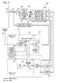
- Fig. 2 is a hard block diagram illustrating the details of the main controller section and the power-source device of the image forming apparatus according to the first embodiment illustrated in Fig. 1 .
- the main controller section 101 is separated into a power-source system A, to which power is supplied in the normal power state and in the power conservation state, and a power-source system B, to which power is supplied in the normal power state although supply of power is stopped in the power conservation state.
- a power-source control unit 312, a network processing unit 313, a timer unit 314, the memory unit 315 of the main controller section 101 and the sensor section 600, which is described above, belong to the power-source system A.
- the HDD unit 316, a CPU unit 317, and an image processing unit 318 of the main controller section 101 belong to the power-source system B. Note that one portion of an operation section 500 that accepts a user operation belongs to the power-source system A, and the remaining portion belongs to the power-source system B.
- the main controller section 101 has the power-source control unit 312, the network processing unit 313, the timer unit 314, the memory unit 315, the HDD unit 316, the CPU unit 317, and the image processing unit 318.
- the power-source control unit 312 controls supply of power supplied to the individual sections of the image forming apparatus 100 and interruption of the supply of power.
- the power-source control unit 312 controls a relay of the power-source device 300, which is described below, so that the relay will be turned on/off.
- the power-source control unit 312 makes the relay 301 enter an off-state, whereby supply of power to the power-source system B, the printer section 102, and the scanner section 103 is stopped and the image forming apparatus 100 enters the power conservation state. Note that, when a main switch SW is turned off by a user operation, supply of power to the power-source system A is stopped.
- the network processing unit 313 receives PDL data transmitted from the PC 107 via the network 106, or transmits configuration information of the image forming apparatus 100 to the network 106.
- the network processing unit 313 is connected to the power-source control unit 312 so as to be capable of communicating with the power-source control unit 312.
- the network processing unit 313 in the power conservation state, when the network processing unit 313 receives, via the network 106, for example, a network packet whose destination is the image forming apparatus 100, the network processing unit 313 outputs an activation signal to the power-source control unit 312.
- the power-source control unit 312 that has received the activation signal makes the relay 301 enter an on-state, thereby returning the image forming apparatus 100 from the power conservation state to the normal power state.
- the local interface outputs the activation signal to the power-source control unit 312.
- the timer unit 314 measures a time.
- the timer unit 314 is used to measure a predetermined time period that is measured in order that the image forming apparatus 100 shift from the normal power state to the power conservation state.
- the memory unit 315 is a volatile memory such as DDRSDRAM, and is a main memory that stores, for example, user data generated by, for example, a control program executed by the CPU unit 317. Note that, in the above-described suspend state, energization of the memory unit 315 is maintained.
- the HDD unit 316 is a storage device for temporarily storing a program to be executed by the CPU unit 317 or PDL data transmitted from the network 106.
- the CPU unit 317 is a central processing device that performs control on the individual sections of the image forming apparatus 100.
- the CPU unit 317 performs, on the basis of a control program stored in the HDD unit 316, the copy function, the print function, or the like of the image forming apparatus 100.
- the image processing unit 318 is connected to the CPU unit 317, the printer section 102, and the scanner section 103 so as to be capable of communicating with the CPU unit 317, the printer section 102, and the scanner section 103.
- the image processing unit 318 performs image processing, such as color space conversion, on image data read by the scanner section 103 and image data that is generated on the basis of PDL data received from the PC 107. Then, the image processing unit 318 converts the image data, which has been subjected to image processing, into bitmap data.
- the bitmap data is output to the printer section 102, and the printer section 102 forms an image on a sheet of paper on the basis of the bitmap data.
- the power-source device 300 includes the main switch SW, the relay 301, a power-source section 302, a power-supply section 306, and a power-supply section (the power-source system A) 305.
- the main switch SW is a seesaw switch whose state is switched between an on-state and an off-state in a toggle manner by the user.
- the user makes the main switch SW enter the off-state, whereby the image forming apparatus 100 enters the power-off state in which supply of power to the individual sections of the image forming apparatus is stopped.
- the relay 301 enters, using control of the power-source control unit 312, the on-state or off-state.
- the alternating current power source is provided for the power-source section 302 (a high-voltage power-source unit 303, a low-voltage power-source unit 304) via the AC plug 105.
- the relay 301 may be a mechanical relay which enters, using electromagnetic induction, the on-state or off-state, or may be a semiconductor switch.
- the power-source section 302 includes the high-voltage power-source unit 303 and the low-voltage power-source unit 304.
- the high-voltage power-source unit 303 converts the alternating current power source, which is input via the AC plug 105, into a direct current power source, and outputs a voltage of, for example, 24 V.
- the low-voltage power-source unit 304 converts the alternating current power source, which is input via the AC plug 105, into a direct current power source, and outputs a voltage of, for example, 12 V.
- the high-voltage power-source unit 303 is a power source that is, for example, used for a motor driving power source and a heater of a fixing unit of the printer section 102 and the scanner section 103.
- the low-voltage power-source unit 304 is a power source that is used for control units of the printer section 102 and the scanner section 103 and the power-source system B of the main controller section 101.
- the power-supply section 306 has a scanner-section power-supply unit 307, a printer-section power-supply unit 308, and a power-supply unit (the power-source system B) 309.
- the scanner-section power-supply unit 307 supplies, using the high-voltage power-source unit 303 as an input source, power to a driving system of the scanner section 103.
- the scanner-section power-supply unit 307 supplies, using the low-voltage power-source unit 304 as an input source, power to the control unit of the scanner section 103.
- the printer-section power-supply unit 308 supplies, using the high-voltage power-source unit 303 as an input source, power to a driving system of the printer section 102.
- the printer-section power-supply unit 308 supplies, using the low-voltage power-source unit 304 as an input source, power to the control unit of the printer section 102.
- the power-supply unit (the power-source system B) 309 supplies, using the low-voltage power-source unit 304 as an input source, power to the power-source system B of the main controller section 101.
- the power-supply section (the power-source system A) 305 converts the alternating current power source into a direct current power source, and outputs a voltage of, for example, 3.3 V to the power-source system A (the sensor section 600, the power-source control unit 312, the network processing unit 313, the timer unit 314, the memory unit 315).
- Fig. 3 is a hard block diagram illustrating the details of the operation section 500 of the image forming apparatus according to the first embodiment illustrated in Fig. 1 .
- the operation section 500 has a display unit 524 that displays, for example, various types of setting screens of the image forming apparatus 100, a key unit 525 that is operated by the user, and so forth.
- the operation section 500 is separated into the power-source system A and the power-source system B.
- a main-power-source LED 511, the power saving button 512 (return means), and a human-presence LED unit 513 of the operation section 500 belong to the power-source system A. Furthermore, a microcomputer 521, a touch-panel controller 522, an LCD controller 523, the display unit 524, the key unit 525, a buzzer 526, and a notification LED unit 527 of the operation section 500 belong to the power-source system B.
- the main-power-source LED 511 is an LED that performs illumination in the case where the image forming apparatus 100 is in the normal power state and in the case where the image forming apparatus 100 is in the power conservation state.
- the power saving button 512 is a button for shifting the image forming apparatus 100 that is in the normal power state to the power conservation state. Furthermore, the power saving button 512 is also a button for shifting the image forming apparatus 100 that is in the power conservation state to the normal power state. The user presses the power saving button 512, whereby the user can shift the image forming apparatus 100 from the power conservation state to the normal power state, or from the normal power state to the power conservation state.
- the power saving button 512 is connected to the power-source control unit 312, and the power-source control unit 312 is notified that the power saving button 512 has been pressed.
- the power-source control unit 312 that has received this notification switches the relay 301 so that the relay 301 is turned on or off.
- the human-presence LED unit (notification means) 513 performs illumination in the case where an object, such as a person, in the vicinity of the image forming apparatus 100 has been detected by the sensor section 600. Note that the details of the human-presence LED unit 513 will be described below.
- the microcomputer 521 controls operations of the individual units of the operation section 500. Furthermore, the microcomputer 521 is connected to the CPU unit 317 of the main controller section 101 so as to be capable of communicating with the CPU unit 317.
- the display unit 524 has an LCD panel that displays an image and a touch panel that is provided on the surface of the LCD panel.
- the touch-panel controller 522 receives an input that has been provided for the touch panel which is provided on the surface of the LCD panel of the display unit 524.
- the LCD controller 523 controls the LCD panel so that an image will be displayed on the LCD panel of the display unit 524.
- the key unit 525 includes a ten key for inputting the number of sheets to be printed, a start key for stating execution of the copy function, and so forth.
- the buzzer 526 outputs a sound, for example, when an error occurs.
- the notification LED unit 527 is an LED which provides a notification that the image forming apparatus 100 is performing a job or that an error occurs in the image forming apparatus 100.
- Fig. 4 is a diagram illustrating detection areas of the sensor section 600.
- the sensor section 600 has a detection area 1 (a first detection range) that is a range in which the sensor section 600 can detect an object, and a detection area 2 (a second detection range) that is smaller than the detection area 1.
- a detection area 1 a first detection range
- a detection area 2 a second detection range
- Fig. 5 is a diagram illustrating the details of the sensor section 600.
- the sensor section 600 has a human-body detection sensor 601 and an analysis circuit 602.
- the sensor section 600 belongs to the power-source system A. In the power conservation state, power is supplied to the sensor section 600 from the power-supply section (the power-source system A) 305.
- the human-body detection sensor 601 is an infrared array sensor in which reflection-type infrared sensors that radiate infrared rays and that detect reflected light of the infrared rays are arranged in a matrix form.
- the human-body detection sensor 601 includes a total of 25 infrared sensor elements (infrared sensor elements A1 to A5, B1 to B5, C1 to C5, D1 to D5, and E1 to E5) that are arranged in five rows and five columns.
- the human-body detection sensor 601 is not limited to the above-mentioned infrared array sensor.
- the human-body detection sensor 601 may be an infrared line sensor in which infrared sensors are arranged in a line.
- the human-body detection sensor 601 may be a pyroelectric array sensor in which pyroelectric sensors that sense infrared rays radiated from a person and that determine whether a person is present or absent in accordance with the amount of change in the infrared rays are arranged in a matrix form, or may be a pyroelectric line sensor in which pyroelectric sensors are arranged in a line.
- the human-body detection sensor 601 may be constituted by the infrared sensors and the pyroelectric sensors, which are mentioned above.
- a camera may be utilized as the human-body detection sensor 601.
- the above-mentioned detection area 1 is an aggregate region that is an aggregate of regions which are detected by the infrared sensor elements A1 to A5, B1 to B5, C1 to C5, D1 to D5, and E1 to E5 of the human-body detection sensor 601.
- the detection area 2 is an aggregate region that is an aggregate of regions which are detected by the infrared sensor elements C3, E3, and D3 of the human-body detection sensor 601.
- the detection area 2 may be a region which is detected by a specific infrared sensor element (for example, the infrared sensor element E3) of the human-body detection sensor 601. Note that the relationships between the detection areas and the infrared sensor elements can be appropriately selected by the user.
- the analysis circuit 602 is a small-scale data processing circuit that has a processor, such as a microcomputer, and a memory.
- the analysis circuit 602 receives a detection signal from the human-body detection sensor 601, and determines an area in which an object has been detected. In the case where the analysis circuit 602 determines that an object has been detected in the detection area 1 described below, the analysis circuit 602 outputs an illumination signal having a Hi level to the human-presence LED unit 513 so that the light-emitting element LED of the human-presence LED unit 513 will perform illumination.
- the analysis circuit 602 determines that an object has been detected in the detection area 2 described below, the analysis circuit 602 outputs the activation signal to the power-source control unit 312 so that the image forming apparatus 100 will return from the power conservation state to the normal power state.
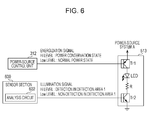
- Fig. 6 is a diagram illustrating the details of the human-presence LED unit 513.
- the human-presence LED unit 513 has a transistor Tr1, a transistor Tr2, the light-emitting element LED (a light emitting section), and a resistor R.
- an energization signal having a Hi level is input from the power-source control unit 312 of the main controller section 101 to the transistor Tr1 of the human-presence LED unit 513. Accordingly, the transistor Tr1 enters an on-state. Accordingly, the voltage of the power-source system A is applied to the anode of the light-emitting element LED.
- the illumination signal having a Hi level is input to the transistor Tr2 from the analysis circuit 602. Accordingly, the cathode of the LED has the ground potential. Accordingly, the light-emitting element LED performs illumination.
- the illumination signal having a Low level is input from the analysis circuit 602 to the transistor Tr2. Accordingly, the LED stops performing illumination.
- the energization signal having a Low level is input from the power-source control unit 312 to the transistor Tr1, and the transistor Tr1 enters the off-state. Accordingly, the voltage of the power-source system A is no longer applied to the anode of the light-emitting element LED, and the LED stops performing illumination.
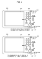
- the light-emitting element LED of the human-presence LED unit 513 is provided inside the power saving button 512 that is transparent.
- the light-emitting element LED performs illumination.
- the light-emitting element LED stops performing illumination. Note that, here, an example in which the light-emitting element LED performs illumination is described.
- an illumination control circuit is provided in the human-presence LED unit 513, whereby the light-emitting element LED may be made to blink.
- an interval, the light-emitting element LED blinking at the intervals, may be able to be changed by the illumination control circuit.
- a PWM control circuit is provided in the human-presence LED unit 513, whereby the brightness of the light-emitting element LED may be able to be changed. Accordingly, the position of the power saving button 512 can be emphasized using the manner in which the light-emitting element LED performs illumination.
- the power-source control unit 312 executes a control program that is stored in the HDD unit 316 and that is based on a flowchart of Fig. 8 , thereby performing the process described blow.
- the power-source control unit 312 determines whether or not conditions under which the image forming apparatus 100 is to shift from the normal power state to the power conservation state are satisfied (S101).
- the image forming apparatus 100 shifts from the normal power state to the power conservation state.
- the power-source control unit 312 turns off the relay 301 of the power-source device 300 (S102). Accordingly, supply of power from the alternating current power source to the power-source section 302 is stopped. Thus, supply of power to the individual units of the main controller section 101 and one portion of the operation section 500, which belong to the power-source system B, and the printer section 102 and the scanner section 103 is stopped, and the image forming apparatus 100 enters the power conservation state.
- the power-source control unit 312 outputs the energization signal having a Hi level to the transistor Tr1 of the human-presence LED unit 513, whereby the transistor Tr1 is switched to the on-state. Accordingly, a voltage is applied to the anode of the light-emitting element LED, and the light-emitting element LED enters a state of being able to perform illumination.
- the processor such as a microcomputer, included in the analysis circuit 602 executes a control program that is stored in a memory of the sensor section 600 and that is based on a flowchart of Fig. 9 , thereby performing the process described below.
- Power is supplied, in the power conservation state, from the power-source device 300 to the sensor section 600 that belongs to the power-source system A and that includes the analysis circuit 602. Individual steps described below are performed when the image forming apparatus 100 is in the power conservation state.
- the processor of the analysis circuit 602 determines whether the human-body detection sensor 601 has detected an object (S201). Specifically, in the case where the processor of the analysis circuit 602 has received the detection signal from the human-body detection sensor 601, the processor of the analysis circuit 602 determines that the human-body detection sensor 601 has detected an object (S201:Yes). In the case where the processor of the analysis circuit 602 determines that the human-body detection sensor 601 has detected an object (S201:Yes), the processor of the analysis circuit 602 determines which area is the area in which the object has been detected (S202).
- the processor of the analysis circuit 602 determines that the object has been detected in the detection area 1, the processor of the analysis circuit 602 outputs the illumination signal having a Hi level to the transistor Tr2 of the human-presence LED unit 513 (S203). While the object is being continuously detected in the detection area 1, the processor of the analysis circuit 602 continuously outputs the illumination signal having a Hi level to the transistor Tr2. Accordingly, the transistor Tr2 is switched to an on-state. As a result, the light-emitting element LED emits light, and the power saving button 512 is emphasized.
- the processor of the analysis circuit 602 waits until a predetermined time period (for example, 100 ms) elapses (S204).
- a predetermined time period for example, 100 ms
- the processor of the analysis circuit 602 determines whether or not the object has been detected in the detection area 2 (S205).
- the processor of the analysis circuit 602 outputs the activation signal to the power-source control unit 312 (S206).
- the power-source control unit 312 When the power-source control unit 312 receives the activation signal from the processor of the analysis circuit 602 described above, the power-source control unit 312 makes the relay 301 of the power-source device 300 enter the on-state. Accordingly, the image forming apparatus 100 returns from the power conservation state to the normal power state.
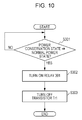
- the power-source control unit 312 executes a control program that is stored in the HDD unit 316 and that is based on a flowchart of Fig. 10 , thereby performing the process described blow.
- the power-source control unit 312 determines whether or not conditions under which the image forming apparatus 100 is to shift from the power conservation state to the normal power state are satisfied (S301).
- the image forming apparatus 100 shifts from the power conservation state to the normal power state.
- the power-source control unit 312 performs control so that the relay 301 of the power-source device 300 will enter the on-state. Accordingly, power is supplied from the alternating current power source to the power-source section 302 and the power-supply section 306. Thus, supply of power to the individual units of the main controller section 101 and one portion of the operation section 500, which belong to the power-source system B, and the printer section 102 and the scanner section 103 starts, and the image forming apparatus 100 enters the normal power state.
- the power-source control unit 312 outputs the energization signal having a Low level to the transistor Tr1 of the human-presence LED unit 513, whereby the transistor Tr1 is switched to the off-state. Accordingly, the voltage is no longer applied to the anode of the light-emitting element LED, and the light-emitting element LED enters a state of being unable to perform illumination (a state in which, even when an object is detected in the detection area 1 by the human-body detection sensor 601 and when the illumination signal having a Hi level is input, the light-emitting element LED does not emit light).
- the detection area of the human-body detection sensor 601 is divided into two detection areas that are the detection area 1 and the detection area 2.
- the detection area of the human-body detection sensor 601 is subdivided into detection areas compared with those in the first embodiment. Note that a description of a duplicate portion of the first embodiment will be omitted.
- Fig. 11 is a diagram illustrating detection areas of the human-body detection sensor 601 in the second embodiment of the present invention.
- the detection area 1 in the first embodiment is subdivided into a detection area 1-1, a detection area 1-2, and a detection area 1-3.
- the detection area 2 is similar to that in the first embodiment, and is a range in which, in the case where an object has been detected, the image forming apparatus 100 is returned from the power conservation state to the normal power state.
- a sensor which is utilized as the human-body detection sensor 601 in the second embodiment may include a plurality of sensors, and the plurality of sensors may detect the individual detection areas.
- the human-body detection sensor 601 may be an array sensor in which sensor elements are arranged in a matrix form or in a line, and which detects the individual detection areas.
- the processor such as a microcomputer, included in the analysis circuit 602 executes a control program that is stored in the memory of the sensor section 600 and that is based on a flowchart of Fig. 12 , thereby performing the process described below.
- Power is supplied, in the power conservation state, from the power-source device 300 to the sensor section 600 that belongs to the power-source system A and that includes the analysis circuit 602. Individual steps described below are performed when the image forming apparatus 100 is in the power conservation state.
- the analysis circuit 602 determines whether the human-body detection sensor 601 has detected an object (S1001). Specifically, in the case where the analysis circuit 602 has received the detection signal from the human-body detection sensor 601, the analysis circuit 602 determines that the human-body detection sensor 601 has detected an object (S1001:Yes). In the case where the analysis circuit 602 determines that the human-body detection sensor 601 has detected an object (S1001:Yes), the analysis circuit 602 determines which area is the area in which the object has been detected (S1002, S1003).
- the analysis circuit 602 determines that the object has been detected in the detection area 1-1 (S1003:the detection area 1-1), the analysis circuit 602 outputs an illumination signal A having a Hi level to the transistor Tr2 described below (S1004). Furthermore, in the case where the analysis circuit 602 determines that the object has been detected in the detection area 1-2, the analysis circuit 602 outputs an illumination signal B having a Hi level to a transistor Tr3 described below (S1005). Moreover, in the case where the analysis circuit 602 determines that the object has been detected in the detection area 1-3, the analysis circuit 602 outputs an illumination signal C having a Hi level to a transistor Tr4 described below (S1006).
- the analysis circuit 602 waits until a predetermined time period (for example, 100 ms) elapses (S1007). After the predetermined time period has elapsed, the analysis circuit 602 determines whether or not the object has been detected in the detection area 2 (S1008). After the predetermined time period has elapsed, in the case where the analysis circuit 602 has detected the object again in the detection area 2 (S1008:Yes), the analysis circuit 602 outputs the activation signal to the power-source control unit 312 (S1009).
- a predetermined time period for example, 100 ms
- the power-source control unit 312 When the power-source control unit 312 has received the above-mentioned notification from the analysis circuit 602, the power-source control unit 312 makes the relay 301 of the power-source device 300 enter the on-state. Accordingly, the image forming apparatus 100 returns from the power conservation state to the normal power state.
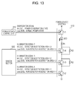
- the human-presence LED unit 513 has the transistors Tr1, Tr2, Tr3, and Tr4, the light-emitting element LED, and resistors R1, R2, and R3.
- the transistors Tr1, Tr2, Tr3, and Tr4 are connected in series.
- the resistor R2 is connected in parallel with the transistor Tr3, and the resistor R3 is connected in parallel with the transistor Tr4.
- the illumination signal A having a Hi level is input to the transistor Tr2, and the transistor Tr2 enters the on-state.
- the transistors Tr3 and Tr4 are in an off-state. Accordingly, a current flows through the light-emitting element LED in accordance with a total resistance value of the resistors R1, R2, and R3, and the light-emitting element LED emits light.
- the illumination signal B having a Hi level is input to the transistor Tr3, and, in addition to the transistor Tr2, the transistor Tr3 enters an on-state.
- the detection area 1-2 is a region included in the detection area 1-1, both the transistor Tr2 and the transistor Tr3 enter the on-state.
- the transistors Tr4 is in the off-state. Accordingly, a current flows through the light-emitting element LED in accordance with a total resistance value of the resistors R1 and R3, and the light-emitting element LED emits light.
- the brightness of the light-emitting element LED when the object has been detected in the detection area 1-2 is higher than the brightness of the light-emitting element LED when the object has been detected in the detection area 1-1.
- the illumination signal C having a Hi level is input to the transistor Tr4, and, in addition to the transistors Tr2 and Tr3, the transistor Tr4 enters an on-state.
- the detection area 1-3 is a region included in the detection area 1-2, all of the transistors Tr2, Tr3, and Tr4 enter the on-state. Accordingly, a current flows through the light-emitting element LED in accordance with a resistance value of the resistor R1, and the light-emitting element LED emits light.
- the brightness of the light-emitting element LED when the object has been detected in the detection area 1-3 is higher than the brightness of the light-emitting element LED when the object has been detected in the detection areas 1-1 and 1-2.
- the luminance of the light-emitting element LED gradually increases as an object approaches the image forming apparatus 100.
- the brightness of the light-emitting element LED provided inside the power saving button 512 increases.
- the user can easily grasp the position of the power saving button 512. Accordingly, even in the case where the image forming apparatus does not automatically return to the normal power state, without looking for the button for shifting the image forming apparatus to the normal power state, the user can press the power saving button 512.
- light-emitting elements LED10, LED20, and LED30 are provided in an operation section 500 of an image forming apparatus according to the third embodiment.
- the light-emitting elements LED10, LED20, and LED30 are arranged in a line.
- the light-emitting element LED10 is placed so as to be farthest from the power saving button 512.
- the light-emitting element LED30 is placed so as to be nearest to the power saving button 512.
- the human-presence LED unit 513 in the third embodiment has transistors Tr1, Tr10, Tr20, and Tr30, the light-emitting element LED10, the light-emitting element LED20, the light-emitting element LED30, and resistors R10, R20, and R30.
- the transistors Tr10, Tr20, and Tr30 are connected in parallel.
- the resistor R10, the transistor Tr10, and the light-emitting element LED10 are connected in series.
- the resistor R20, the transistor Tr20, and the light-emitting element LED20 are connected in series.
- the resistor R30, the transistor Tr30, and the light-emitting element LED30 are connected in series.
- the detection areas of the human-body detection sensor 601 of the image forming apparatus 100 according to the third embodiment are similar to those in the second embodiment.
- the illumination signal A having a Hi level to the transistor Tr10, and the transistor Tr10 enters an on-state.
- the transistors Tr20 and Tr30 are in an off-state. Accordingly, a current flows through the light-emitting element LED10, and the light-emitting element LED10, which is farthest from the power saving button 512, emits light.
- the illumination signal B having a Hi level is input to the transistor Tr20, and, in addition to the transistor Tr10, the transistor Tr20 enters an on-state.
- the transistor Tr30 is in the off-state. Accordingly, a current flows through the light-emitting elements LED10 and 20, and the light-emitting elements LED10 and 20 emit light.
- the illumination signal C having a Hi level is input to the transistor Tr30. Accordingly, in addition to the transistors Tr10 and Tr20, the transistor Tr30 enters an on-state. As a result, a current flows through the light-emitting elements LED10, 20, and 30, and the light-emitting elements LED10, 20, and 30 emit light.
- the number of light-emitting elements LED that emit light increases.
- the light-emitting elements LED perform illumination in order from the light-emitting element LED farthest from the power saving button 512.
- the number of light-emitting elements that emit light of the power saving button 512 increases, and, the light-emitting elements LED perform illumination in order from the light-emitting element LED that is most distant from the power saving button 512.
- the user can easily grasp the position of the power saving button 512. Accordingly, even in the case where the image forming apparatus does not automatically return to the normal power state, without looking for the button for shifting the image forming apparatus to the normal power state, the user can press the power saving button 512.
- the image forming apparatus 100 when the image forming apparatus 100 does not automatically return to the normal power state, in order to make the user recognize the power saving button 512 that the user should operate next, the light-emitting element LED is placed inside or in the vicinity of the power saving button 512.
- the NFC Near Field Communication
- an image forming apparatus 100 includes the NFC section 700, in addition to the printer section 102, the scanner section 103, and so forth described above.
- the NFC section 700 reads, from a mobile terminal or a card (hereinafter, referred to as a "mobile terminal or the like"), information stored in the mobile terminal or the like. Identification information of the user who is to use the image forming apparatus 100 is stored in the mobile terminal or the like, and the NFC section 700 acquires the identification information from the mobile terminal or the like.
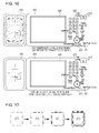
- the light-emitting element LED is placed inside the NFC section 700. Then, in the case where the human-body detection sensor 601 has detected an object in the detection area 1, the light-emitting element LED emits light. Accordingly, a portion of the NFC section 700 that is a portion which the mobile terminal or the like is to come close to is made to emit light.
- the user who comes close to the image forming apparatus 100 can easily recognize the position of the NFC section that the user should operate next.
- the NFC section 700 is described.
- the NFC section 700 may be a card reader section.
- the power saving button 512 described above may be made to emit light.
- the brightness of the NFC section 700 may gradually increase.
- the power saving button 512 or the NFC section 700 is emphasized using emission of an LED.
- the present invention is not limited thereto.
- a sound may be output by the buzzer 526.
- the present invention is applied to an MFP having a plurality of functions.
- the present invention is not limited thereto.
- the present invention may be applied to an SFP (Singlefunction Peripheral) having one function among the scanner function, the print function, and the fax function.
- infrared sensors that detect infrared rays radiated from an object (a static body or a body capable of movement) are used.
- the present invention is not limited thereto. Sensors that detect movement of an object may be used. Note that the method for detecting an object is not limited thereto.
- Functions illustrated in the flowcharts in the present embodiments can be realized also by executing, with a processing device (a CPU, a processor) of a personal computer or the like, software (a program) acquired via a network or various types of storage media.
- a processing device a CPU, a processor
- software a program acquired via a network or various types of storage media.
Landscapes
- Engineering & Computer Science (AREA)
- Theoretical Computer Science (AREA)
- Multimedia (AREA)
- Signal Processing (AREA)
- Physics & Mathematics (AREA)
- General Physics & Mathematics (AREA)
- General Engineering & Computer Science (AREA)
- Human Computer Interaction (AREA)
- Microelectronics & Electronic Packaging (AREA)
- Control Or Security For Electrophotography (AREA)
- Facsimiles In General (AREA)
- Accessory Devices And Overall Control Thereof (AREA)
- Power Sources (AREA)
Abstract
Description
- The present invention relates to an image forming apparatus or the like that includes a human-body detection sensor which detects an object such as a person in the vicinity thereof.
- A technique is known, in which a user returns, by pressing a power saving button provided in an image forming apparatus, the image forming apparatus that is in a power conservation state to a normal power state. Furthermore, in recent years, an image forming apparatus has been proposed, which detects, using a human-body detection sensor, a person who has come close to the image forming apparatus even when a user does not press the power saving button, and which automatically returns from the power conservation state to the normal power state (See PTL 1).
- In
PTL 1, a technique is disclosed, in which an image forming apparatus is returned, using two human-body detection sensors having different detection ranges, from the power conservation state to the normal power state. In the image forming apparatus disclosed inPTL 1, when a person who has come close to the image forming apparatus has been detected by a first human-body detection sensor having a large detection range, a second human-body detection sensor whose detection range is smaller than that of the first human-body detection sensor is activated. Then, when the person has been detected by the activated second human-body detection sensor, the image forming apparatus returns from the power conservation state to the normal power state. - However, in the image forming apparatus using human-body detection sensors, which is disclosed in
PTL 1 described above, there is a case in which the image forming apparatus is not able to automatically return from the power conservation state to the normal power state, depending on a position at which a user stands up with respect to the image forming apparatus. For example, in the case where the user exists at the blind spot of the second human-body detection sensor, it is impossible for the second human-body detection sensor to detect the user. Thus, it is impossible for the image forming apparatus to automatically return from the power conservation state to the normal power state. - In the case where the image forming apparatus does not automatically return from the power conservation state to the normal power state, the user presses the power saving button, thereby returning the image forming apparatus to the normal power state. However, for the user who is accustomed to using the image forming apparatus that automatically returns, using a human-body detection sensor, to the normal power state, an operation for manually returning the image forming apparatus to the normal power state is an operation that the user is not accustomed to performing. Therefore, in front of the image forming apparatus, the user is forced to perform a task for returning the image forming apparatus to the normal power state.
- PTL 1: Japanese Patent Laid-Open No.
2012-17796 - It is an object of the present invention to provide an image forming apparatus or the like which can make a user recognize a position which the user should operate in order to manually return the image forming apparatus to a normal power state, even in the case where the image forming apparatus does not automatically return, using a human-body detection sensor, from a power conservation state to the normal power state.
- An image forming apparatus according to the present invention is an image forming apparatus that enters a first power state in which a predetermined function is executable and a second power state in which the predetermined function is not executable. The image forming apparatus includes detection means for detecting an object in the vicinity of the image forming apparatus; an operation section that a user operates in order to shift the image forming apparatus from the second power state to the first power state; notification means for, in a case where an object has been detected by the detection means, providing a notification of information indicating a position of the operation section; and power-source control means for, in a case where the operation section has been operated by the user, shifting the image forming apparatus from the second power state to the first power state.
- According to the present invention, a user can be made to recognize a position which the user should operate in order to manually return the image forming apparatus from the second power state to the first power state, even in the case where the image forming apparatus does not automatically return, using a human-body detection sensor, from the second power state to the first power state. Brief Description of Drawings
-
- [
Fig. 1] Fig. 1 is a diagram of an overall configuration of an image forming apparatus according to a first embodiment. - [
Fig. 2] Fig. 2 is a circuit diagram of a power source of the image forming apparatus. - [
Fig. 3] Fig. 3 is a hard block diagram of an operation section of the image forming apparatus. - [
Fig. 4] Fig. 4 is a diagram illustrating detection areas of a sensor section of the image forming apparatus. - [
Fig. 5] Fig. 5 is a diagram illustrating the details of the sensor section of the image forming apparatus. - [
Fig. 6] Fig. 6 is a diagram illustrating the details of a human-presence LED unit of the operation section. - [
Fig. 7] Fig. 7 is a diagram of the operation section, which illustrates a state in which a light-emitting element LED emits light. - [
Fig. 8] Fig. 8 is a flowchart illustrating a process performed by a power-source control unit in the case where the image forming apparatus shifts from a normal power state to a power conservation state. - [
Fig. 9] Fig. 9 is a flowchart illustrating a process performed by an analysis circuit of the sensor section in the power conservation state. - [
Fig. 10] Fig. 10 is a flowchart illustrating a process performed by the power-source control unit in the case where the image forming apparatus shifts from the power conservation state to the normal power state. - [
Fig. 11] Fig. 11 is a diagram illustrating detection areas of a sensor section of an image forming apparatus according to a second embodiment. - [
Fig. 12] Fig. 12 is a flowchart illustrating a process performed by an analysis circuit of the sensor section in the case where the image forming apparatus according to the second embodiment is in the power conservation state. - [
Fig. 13] Fig. 13 is a diagram illustrating the details of a human-presence LED unit of the image forming apparatus according to the second embodiment. - [
Fig. 14] Fig. 14 is a diagram illustrating the details of a human-presence LED unit of an image forming apparatus according to a third embodiment. - [
Fig. 15] Fig. 15 is a diagram of an operation section, which illustrates a state in which light-emitting elements LED of the image forming apparatus according to the third embodiment emit light. - [
Fig. 16] Fig. 16 is a diagram of an operation section, which illustrates a state in which a light-emitting element LED of an image forming apparatus according to a fourth embodiment emits light. - [
Fig. 17] Fig. 17 is a diagram illustrating a state in which an NFC section of the image forming apparatus according to the fourth embodiment emits light. Description of Embodiments - Hereinafter, embodiments of the present invention will be described using the drawings.
-
Fig. 1 is a schematic diagram of animage forming apparatus 100 according to a first embodiment of the present invention. - The
image forming apparatus 100 is an MFP (Multifunction Peripheral) having a plurality of functions such as a scanner function, a print function, and a fax function. Theimage forming apparatus 100 enters a plurality of power states, such as a normal power state (a first power state) in which the scanner function and the print function, which are mentioned above, are executable, and a power conservation state (a second power state) in which the scanner function and the print function are not executable. The power conservation state is a power state in which the amount of power consumed is smaller than that in the normal power state. In the power conservation state, data is received from a network or a user operates apower saving button 512, which is described below, whereby theimage forming apparatus 100 can return to the normal power state. - Note that the
image forming apparatus 100 may enter a suspend state or a hibernation state other than the normal power state and the power conservation state, which are described above. The suspend state is a state in which theimage forming apparatus 100 can return to the normal power state at a high speed. In the suspend state, energization of amemory unit 315, which is described below, is maintained, and, using a state of theimage forming apparatus 100 immediately prior to entering the suspend state that is a state stored in thememory unit 315, theimage forming apparatus 100 returns to the normal power state at a high speed. Furthermore, the hibernation state is also a state in which theimage forming apparatus 100 can return to the normal power state at a high speed. In the hibernation state, the power state is similar to a power-off state in which supply of power to the individual sections of theimage forming apparatus 100 is stopped, and supply of power to the individual sections of theimage forming apparatus 100 is stopped. However, the difference from the power-off state is that the state of theimage forming apparatus 100 immediately prior to entering the hibernation state is stored in anHDD unit 316 which is described below. In the case of returning from the hibernation state to the normal power state, using the state of theimage forming apparatus 100 that is the state stored in theHDD unit 316, theimage forming apparatus 100 returns to the normal power state at a high speed. - As illustrated in
Fig. 1 , theimage forming apparatus 100 includes amain controller section 101, aprinter section 102, ascanner section 103, asensor section 600, anAC plug 105, and a power-source device 300. Theprinter section 102 forms an image on a sheet-shaped recording medium (a sheet of paper), for example, in accordance with an electrophotographic system. Thescanner section 103 optically reads an image from an original document, and performs conversion into a digital image. Themain controller section 101 controls the individual sections of theimage forming apparatus 100. Furthermore, themain controller section 101 is connected to a PC 107 via anetwork 106. Thenetwork 106 is a local area network (LAN), such as USB (Universal Serial Bus), or a wide area network (WAN), such as the Internet, and it does not matter whether thenetwork 106 is a wired or wireless network. Note that the details of themain controller section 101 will be described below. TheAC plug 105 is inserted into a socket that is provided outside the apparatus. An alternating current power source is provided from alternating current Mains electricity to theimage forming apparatus 100 via theAC plug 105. The power-source device 300 to which an alternating current power source is provided from alternating current Mains electricity provides a direct current power source for the individual sections of theimage forming apparatus 100. Furthermore, in the present embodiment, thesensor section 600 is provided so as to detect, for example, a person who exists in the vicinity of theimage forming apparatus 100. The details of the power-source device 300 and thesensor section 600, which are mentioned above, will be described below. - The
PC 107 is connected to theimage forming apparatus 100 via thenetwork 106 or a local interface, such as USB, so as to be capable of communicating with theimage forming apparatus 100. ThePC 107 is a typical computer device which has a CPU, a RAM, and a fixed storage device, such as an HDD, and to which a monitor, a keyboard, a mouse, and so forth are connected. A printer driver program is installed in thePC 107. When the printer driver program is executed by thePC 107, thePC 107 generates PDL data in accordance with a render instruction that an operating system or an application program issues, and transmits the generated PDL data to theimage forming apparatus 100. The PDL data is data that has been converted, by the printer driver program, into a page description language which can be processed by theimage forming apparatus 100. Theimage forming apparatus 100 generates a bitmap image on the basis of the PDL data received from thePC 107. Then, theprinter section 102 forms an image on a sheet of paper on the basis of the generated bitmap image. -
Fig. 2 is a hard block diagram illustrating the details of the main controller section and the power-source device of the image forming apparatus according to the first embodiment illustrated inFig. 1 . - As illustrated in
Fig. 2 , themain controller section 101 is separated into a power-source system A, to which power is supplied in the normal power state and in the power conservation state, and a power-source system B, to which power is supplied in the normal power state although supply of power is stopped in the power conservation state. A power-source control unit 312, anetwork processing unit 313, atimer unit 314, thememory unit 315 of themain controller section 101 and thesensor section 600, which is described above, belong to the power-source system A. Furthermore, theHDD unit 316, aCPU unit 317, and animage processing unit 318 of themain controller section 101 belong to the power-source system B. Note that one portion of anoperation section 500 that accepts a user operation belongs to the power-source system A, and the remaining portion belongs to the power-source system B. - The
main controller section 101 has the power-source control unit 312, thenetwork processing unit 313, thetimer unit 314, thememory unit 315, theHDD unit 316, theCPU unit 317, and theimage processing unit 318. - The power-
source control unit 312 controls supply of power supplied to the individual sections of theimage forming apparatus 100 and interruption of the supply of power. The power-source control unit 312 controls a relay of the power-source device 300, which is described below, so that the relay will be turned on/off. The power-source control unit 312 makes therelay 301 enter an off-state, whereby supply of power to the power-source system B, theprinter section 102, and thescanner section 103 is stopped and theimage forming apparatus 100 enters the power conservation state. Note that, when a main switch SW is turned off by a user operation, supply of power to the power-source system A is stopped. - The
network processing unit 313 receives PDL data transmitted from thePC 107 via thenetwork 106, or transmits configuration information of theimage forming apparatus 100 to thenetwork 106. Thenetwork processing unit 313 is connected to the power-source control unit 312 so as to be capable of communicating with the power-source control unit 312. Regarding thenetwork processing unit 313, in the power conservation state, when thenetwork processing unit 313 receives, via thenetwork 106, for example, a network packet whose destination is theimage forming apparatus 100, thenetwork processing unit 313 outputs an activation signal to the power-source control unit 312. The power-source control unit 312 that has received the activation signal makes therelay 301 enter an on-state, thereby returning theimage forming apparatus 100 from the power conservation state to the normal power state. Furthermore, also in the case where thenetwork processing unit 313 has received data via a local interface such as USB, similarly, the local interface outputs the activation signal to the power-source control unit 312. - The
timer unit 314 measures a time. Thetimer unit 314 is used to measure a predetermined time period that is measured in order that theimage forming apparatus 100 shift from the normal power state to the power conservation state. - The
memory unit 315 is a volatile memory such as DDRSDRAM, and is a main memory that stores, for example, user data generated by, for example, a control program executed by theCPU unit 317. Note that, in the above-described suspend state, energization of thememory unit 315 is maintained. - The
HDD unit 316 is a storage device for temporarily storing a program to be executed by theCPU unit 317 or PDL data transmitted from thenetwork 106. - The
CPU unit 317 is a central processing device that performs control on the individual sections of theimage forming apparatus 100. TheCPU unit 317 performs, on the basis of a control program stored in theHDD unit 316, the copy function, the print function, or the like of theimage forming apparatus 100. - The
image processing unit 318 is connected to theCPU unit 317, theprinter section 102, and thescanner section 103 so as to be capable of communicating with theCPU unit 317, theprinter section 102, and thescanner section 103. Theimage processing unit 318 performs image processing, such as color space conversion, on image data read by thescanner section 103 and image data that is generated on the basis of PDL data received from thePC 107. Then, theimage processing unit 318 converts the image data, which has been subjected to image processing, into bitmap data. The bitmap data is output to theprinter section 102, and theprinter section 102 forms an image on a sheet of paper on the basis of the bitmap data. - As illustrated in
Fig. 2 , the power-source device 300 includes the main switch SW, therelay 301, a power-source section 302, a power-supply section 306, and a power-supply section (the power-source system A) 305. - The main switch SW is a seesaw switch whose state is switched between an on-state and an off-state in a toggle manner by the user. The user makes the main switch SW enter the off-state, whereby the
image forming apparatus 100 enters the power-off state in which supply of power to the individual sections of the image forming apparatus is stopped. - The
relay 301 enters, using control of the power-source control unit 312, the on-state or off-state. When therelay 301 enters the on-state, the alternating current power source is provided for the power-source section 302 (a high-voltage power-source unit 303, a low-voltage power-source unit 304) via theAC plug 105. Note that therelay 301 may be a mechanical relay which enters, using electromagnetic induction, the on-state or off-state, or may be a semiconductor switch. - The power-
source section 302 includes the high-voltage power-source unit 303 and the low-voltage power-source unit 304. The high-voltage power-source unit 303 converts the alternating current power source, which is input via theAC plug 105, into a direct current power source, and outputs a voltage of, for example, 24 V. Furthermore, the low-voltage power-source unit 304 converts the alternating current power source, which is input via theAC plug 105, into a direct current power source, and outputs a voltage of, for example, 12 V. The high-voltage power-source unit 303 is a power source that is, for example, used for a motor driving power source and a heater of a fixing unit of theprinter section 102 and thescanner section 103. The low-voltage power-source unit 304 is a power source that is used for control units of theprinter section 102 and thescanner section 103 and the power-source system B of themain controller section 101. - The power-
supply section 306 has a scanner-section power-supply unit 307, a printer-section power-supply unit 308, and a power-supply unit (the power-source system B) 309. The scanner-section power-supply unit 307 supplies, using the high-voltage power-source unit 303 as an input source, power to a driving system of thescanner section 103. Furthermore, the scanner-section power-supply unit 307 supplies, using the low-voltage power-source unit 304 as an input source, power to the control unit of thescanner section 103. The printer-section power-supply unit 308 supplies, using the high-voltage power-source unit 303 as an input source, power to a driving system of theprinter section 102. Furthermore, the printer-section power-supply unit 308 supplies, using the low-voltage power-source unit 304 as an input source, power to the control unit of theprinter section 102. The power-supply unit (the power-source system B) 309 supplies, using the low-voltage power-source unit 304 as an input source, power to the power-source system B of themain controller section 101. - The power-supply section (the power-source system A) 305 converts the alternating current power source into a direct current power source, and outputs a voltage of, for example, 3.3 V to the power-source system A (the
sensor section 600, the power-source control unit 312, thenetwork processing unit 313, thetimer unit 314, the memory unit 315). -
Fig. 3 is a hard block diagram illustrating the details of theoperation section 500 of the image forming apparatus according to the first embodiment illustrated inFig. 1 . - The
operation section 500 has adisplay unit 524 that displays, for example, various types of setting screens of theimage forming apparatus 100, akey unit 525 that is operated by the user, and so forth. - The
operation section 500 is separated into the power-source system A and the power-source system B. - A main-power-
source LED 511, the power saving button 512 (return means), and a human-presence LED unit 513 of theoperation section 500 belong to the power-source system A. Furthermore, amicrocomputer 521, a touch-panel controller 522, anLCD controller 523, thedisplay unit 524, thekey unit 525, abuzzer 526, and anotification LED unit 527 of theoperation section 500 belong to the power-source system B. - The main-power-
source LED 511 is an LED that performs illumination in the case where theimage forming apparatus 100 is in the normal power state and in the case where theimage forming apparatus 100 is in the power conservation state. - The
power saving button 512 is a button for shifting theimage forming apparatus 100 that is in the normal power state to the power conservation state. Furthermore, thepower saving button 512 is also a button for shifting theimage forming apparatus 100 that is in the power conservation state to the normal power state. The user presses thepower saving button 512, whereby the user can shift theimage forming apparatus 100 from the power conservation state to the normal power state, or from the normal power state to the power conservation state. Thepower saving button 512 is connected to the power-source control unit 312, and the power-source control unit 312 is notified that thepower saving button 512 has been pressed. The power-source control unit 312 that has received this notification switches therelay 301 so that therelay 301 is turned on or off. - The human-presence LED unit (notification means) 513 performs illumination in the case where an object, such as a person, in the vicinity of the
image forming apparatus 100 has been detected by thesensor section 600. Note that the details of the human-presence LED unit 513 will be described below. - The
microcomputer 521 controls operations of the individual units of theoperation section 500. Furthermore, themicrocomputer 521 is connected to theCPU unit 317 of themain controller section 101 so as to be capable of communicating with theCPU unit 317. - The
display unit 524 has an LCD panel that displays an image and a touch panel that is provided on the surface of the LCD panel. - The touch-
panel controller 522 receives an input that has been provided for the touch panel which is provided on the surface of the LCD panel of thedisplay unit 524. - The
LCD controller 523 controls the LCD panel so that an image will be displayed on the LCD panel of thedisplay unit 524. - The
key unit 525 includes a ten key for inputting the number of sheets to be printed, a start key for stating execution of the copy function, and so forth. - The
buzzer 526 outputs a sound, for example, when an error occurs. - The
notification LED unit 527 is an LED which provides a notification that theimage forming apparatus 100 is performing a job or that an error occurs in theimage forming apparatus 100. -
Fig. 4 is a diagram illustrating detection areas of thesensor section 600. - The
sensor section 600 has a detection area 1 (a first detection range) that is a range in which thesensor section 600 can detect an object, and a detection area 2 (a second detection range) that is smaller than thedetection area 1. When an object has been detected in thedetection area 2, theimage forming apparatus 100 that is in the power conservation state returns to the normal power state. -
Fig. 5 is a diagram illustrating the details of thesensor section 600. - As illustrated in
Fig. 5 , thesensor section 600 has a human-body detection sensor 601 and ananalysis circuit 602. Thesensor section 600 belongs to the power-source system A. In the power conservation state, power is supplied to thesensor section 600 from the power-supply section (the power-source system A) 305. - The human-
body detection sensor 601 is an infrared array sensor in which reflection-type infrared sensors that radiate infrared rays and that detect reflected light of the infrared rays are arranged in a matrix form. The human-body detection sensor 601 includes a total of 25 infrared sensor elements (infrared sensor elements A1 to A5, B1 to B5, C1 to C5, D1 to D5, and E1 to E5) that are arranged in five rows and five columns. Note that the human-body detection sensor 601 is not limited to the above-mentioned infrared array sensor. For example, the human-body detection sensor 601 may be an infrared line sensor in which infrared sensors are arranged in a line. Alternatively, the human-body detection sensor 601 may be a pyroelectric array sensor in which pyroelectric sensors that sense infrared rays radiated from a person and that determine whether a person is present or absent in accordance with the amount of change in the infrared rays are arranged in a matrix form, or may be a pyroelectric line sensor in which pyroelectric sensors are arranged in a line. Alternatively, the human-body detection sensor 601 may be constituted by the infrared sensors and the pyroelectric sensors, which are mentioned above. Alternatively, a camera may be utilized as the human-body detection sensor 601. - The above-mentioned
detection area 1 is an aggregate region that is an aggregate of regions which are detected by the infrared sensor elements A1 to A5, B1 to B5, C1 to C5, D1 to D5, and E1 to E5 of the human-body detection sensor 601. Furthermore, thedetection area 2 is an aggregate region that is an aggregate of regions which are detected by the infrared sensor elements C3, E3, and D3 of the human-body detection sensor 601. Note that thedetection area 2 may be a region which is detected by a specific infrared sensor element (for example, the infrared sensor element E3) of the human-body detection sensor 601. Note that the relationships between the detection areas and the infrared sensor elements can be appropriately selected by the user. - The
analysis circuit 602 is a small-scale data processing circuit that has a processor, such as a microcomputer, and a memory. Theanalysis circuit 602 receives a detection signal from the human-body detection sensor 601, and determines an area in which an object has been detected. In the case where theanalysis circuit 602 determines that an object has been detected in thedetection area 1 described below, theanalysis circuit 602 outputs an illumination signal having a Hi level to the human-presence LED unit 513 so that the light-emitting element LED of the human-presence LED unit 513 will perform illumination. Furthermore, in the case where theanalysis circuit 602 determines that an object has been detected in thedetection area 2 described below, theanalysis circuit 602 outputs the activation signal to the power-source control unit 312 so that theimage forming apparatus 100 will return from the power conservation state to the normal power state. -
Fig. 6 is a diagram illustrating the details of the human-presence LED unit 513. - As illustrated in
Fig. 6 , the human-presence LED unit 513 has a transistor Tr1, a transistor Tr2, the light-emitting element LED (a light emitting section), and a resistor R. - In the case where the
image forming apparatus 100 is in the power conservation state, an energization signal having a Hi level is input from the power-source control unit 312 of themain controller section 101 to the transistor Tr1 of the human-presence LED unit 513. Accordingly, the transistor Tr1 enters an on-state. Accordingly, the voltage of the power-source system A is applied to the anode of the light-emitting element LED. - In addition, in the case where an object is detected in the
detection area 1, the illumination signal having a Hi level is input to the transistor Tr2 from theanalysis circuit 602. Accordingly, the cathode of the LED has the ground potential. Accordingly, the light-emitting element LED performs illumination. - In the case where the object is no longer detected in the
detection area 1, the illumination signal having a Low level is input from theanalysis circuit 602 to the transistor Tr2. Accordingly, the LED stops performing illumination. - Moreover, in the case where the
image forming apparatus 100 is in the normal power state, the energization signal having a Low level is input from the power-source control unit 312 to the transistor Tr1, and the transistor Tr1 enters the off-state. Accordingly, the voltage of the power-source system A is no longer applied to the anode of the light-emitting element LED, and the LED stops performing illumination. - As illustrated in
Fig. 7 , the light-emitting element LED of the human-presence LED unit 513 is provided inside thepower saving button 512 that is transparent. In the case where theimage forming apparatus 100 is in the power conservation state and where an object is detected in thedetection area 1 of the human-body detection sensor 601, the light-emitting element LED performs illumination. In the case where the object is no longer detected in thedetection area 1 of the human-body detection sensor 601, the light-emitting element LED stops performing illumination. Note that, here, an example in which the light-emitting element LED performs illumination is described. However, an illumination control circuit is provided in the human-presence LED unit 513, whereby the light-emitting element LED may be made to blink. Furthermore, an interval, the light-emitting element LED blinking at the intervals, may be able to be changed by the illumination control circuit. Moreover, a PWM control circuit is provided in the human-presence LED unit 513, whereby the brightness of the light-emitting element LED may be able to be changed. Accordingly, the position of thepower saving button 512 can be emphasized using the manner in which the light-emitting element LED performs illumination. - Next, the power-
source control unit 312 executes a control program that is stored in theHDD unit 316 and that is based on a flowchart ofFig. 8 , thereby performing the process described blow. - As illustrated in
Fig. 8 , the power-source control unit 312 determines whether or not conditions under which theimage forming apparatus 100 is to shift from the normal power state to the power conservation state are satisfied (S101). - Note that the conditions under which the
image forming apparatus 100 is to shift from the normal power state to the power conservation state are as follows: - (i) the
operation section 500 of theimage forming apparatus 100 is not operated continuously for a predetermined time period; - (ii) data is not received continuously for a predetermined time period from an external device, such as the
PC 107, via thenetwork 106; and - (iii) the
power saving button 512 of theoperation section 500 is pressed. - Regarding the
image forming apparatus 100 according to the present embodiment, in the case where both the condition (i) and the condition (ii) described above are satisfied or in the case where the condition (iii) described above is satisfied, theimage forming apparatus 100 shifts from the normal power state to the power conservation state. - In the case where both the condition (i) and the condition (ii) described above are satisfied or in the case where the condition (iii) described above is satisfied (S101:Yes), the power-
source control unit 312 turns off therelay 301 of the power-source device 300 (S102). Accordingly, supply of power from the alternating current power source to the power-source section 302 is stopped. Thus, supply of power to the individual units of themain controller section 101 and one portion of theoperation section 500, which belong to the power-source system B, and theprinter section 102 and thescanner section 103 is stopped, and theimage forming apparatus 100 enters the power conservation state. - Furthermore, in the present embodiment, the power-
source control unit 312 outputs the energization signal having a Hi level to the transistor Tr1 of the human-presence LED unit 513, whereby the transistor Tr1 is switched to the on-state. Accordingly, a voltage is applied to the anode of the light-emitting element LED, and the light-emitting element LED enters a state of being able to perform illumination. - Next, the processor, such as a microcomputer, included in the
analysis circuit 602 executes a control program that is stored in a memory of thesensor section 600 and that is based on a flowchart ofFig. 9 , thereby performing the process described below. - Power is supplied, in the power conservation state, from the power-
source device 300 to thesensor section 600 that belongs to the power-source system A and that includes theanalysis circuit 602. Individual steps described below are performed when theimage forming apparatus 100 is in the power conservation state. - The processor of the
analysis circuit 602 determines whether the human-body detection sensor 601 has detected an object (S201). Specifically, in the case where the processor of theanalysis circuit 602 has received the detection signal from the human-body detection sensor 601, the processor of theanalysis circuit 602 determines that the human-body detection sensor 601 has detected an object (S201:Yes). In the case where the processor of theanalysis circuit 602 determines that the human-body detection sensor 601 has detected an object (S201:Yes), the processor of theanalysis circuit 602 determines which area is the area in which the object has been detected (S202). In the case where the processor of theanalysis circuit 602 determines that the object has been detected in thedetection area 1, the processor of theanalysis circuit 602 outputs the illumination signal having a Hi level to the transistor Tr2 of the human-presence LED unit 513 (S203). While the object is being continuously detected in thedetection area 1, the processor of theanalysis circuit 602 continuously outputs the illumination signal having a Hi level to the transistor Tr2. Accordingly, the transistor Tr2 is switched to an on-state. As a result, the light-emitting element LED emits light, and thepower saving button 512 is emphasized. - Then, in the case where the processor of the
analysis circuit 602 determines that the object has been detected in thedetection area 2, the processor of theanalysis circuit 602 waits until a predetermined time period (for example, 100 ms) elapses (S204). When the object has been detected in thedetection area 2, the light-emitting element LED stops performing illumination. After the predetermined time period has elapsed, the processor of theanalysis circuit 602 determines whether or not the object has been detected in the detection area 2 (S205). After the predetermined time period has elapsed, in the case where the processor of theanalysis circuit 602 has detected the object again in the detection area 2 (S205), the processor of theanalysis circuit 602 outputs the activation signal to the power-source control unit 312 (S206). - When the power-
source control unit 312 receives the activation signal from the processor of theanalysis circuit 602 described above, the power-source control unit 312 makes therelay 301 of the power-source device 300 enter the on-state. Accordingly, theimage forming apparatus 100 returns from the power conservation state to the normal power state. - Next, the power-
source control unit 312 executes a control program that is stored in theHDD unit 316 and that is based on a flowchart ofFig. 10 , thereby performing the process described blow. - As illustrated in
Fig. 10 , the power-source control unit 312 determines whether or not conditions under which theimage forming apparatus 100 is to shift from the power conservation state to the normal power state are satisfied (S301). - Note that the conditions under which the
image forming apparatus 100 is to shift from the power conservation state to the normal power state are as follows: - (A) an object is detected in the
detection area 2; - (B) data is received from an external device, such as the
PC 107, via thenetwork 106; and - (C) the
power saving button 512 is pressed. - Regarding the
image forming apparatus 100 according to the present embodiment, in the case where any one of the conditions (A), (B), and (C) described above is satisfied, theimage forming apparatus 100 shifts from the power conservation state to the normal power state. - In the case where any one of the conditions (A), (B), and (C) described above is satisfied, the power-
source control unit 312 performs control so that therelay 301 of the power-source device 300 will enter the on-state. Accordingly, power is supplied from the alternating current power source to the power-source section 302 and the power-supply section 306. Thus, supply of power to the individual units of themain controller section 101 and one portion of theoperation section 500, which belong to the power-source system B, and theprinter section 102 and thescanner section 103 starts, and theimage forming apparatus 100 enters the normal power state. - Furthermore, in the present embodiment, the power-
source control unit 312 outputs the energization signal having a Low level to the transistor Tr1 of the human-presence LED unit 513, whereby the transistor Tr1 is switched to the off-state. Accordingly, the voltage is no longer applied to the anode of the light-emitting element LED, and the light-emitting element LED enters a state of being unable to perform illumination (a state in which, even when an object is detected in thedetection area 1 by the human-body detection sensor 601 and when the illumination signal having a Hi level is input, the light-emitting element LED does not emit light). - In the first embodiment described above, an example is described, in which the detection area of the human-
body detection sensor 601 is divided into two detection areas that are thedetection area 1 and thedetection area 2. In a second embodiment, an example will be described, in which the detection area of the human-body detection sensor 601 is subdivided into detection areas compared with those in the first embodiment. Note that a description of a duplicate portion of the first embodiment will be omitted. -
Fig. 11 is a diagram illustrating detection areas of the human-body detection sensor 601 in the second embodiment of the present invention. - In the second embodiment, the
detection area 1 in the first embodiment is subdivided into a detection area 1-1, a detection area 1-2, and a detection area 1-3. Thedetection area 2 is similar to that in the first embodiment, and is a range in which, in the case where an object has been detected, theimage forming apparatus 100 is returned from the power conservation state to the normal power state. - Note that a sensor which is utilized as the human-
body detection sensor 601 in the second embodiment may include a plurality of sensors, and the plurality of sensors may detect the individual detection areas. Alternatively, the human-body detection sensor 601 may be an array sensor in which sensor elements are arranged in a matrix form or in a line, and which detects the individual detection areas. - Next, the processor, such as a microcomputer, included in the
analysis circuit 602 executes a control program that is stored in the memory of thesensor section 600 and that is based on a flowchart ofFig. 12 , thereby performing the process described below. - Power is supplied, in the power conservation state, from the power-
source device 300 to thesensor section 600 that belongs to the power-source system A and that includes theanalysis circuit 602. Individual steps described below are performed when theimage forming apparatus 100 is in the power conservation state. - The
analysis circuit 602 determines whether the human-body detection sensor 601 has detected an object (S1001). Specifically, in the case where theanalysis circuit 602 has received the detection signal from the human-body detection sensor 601, theanalysis circuit 602 determines that the human-body detection sensor 601 has detected an object (S1001:Yes). In the case where theanalysis circuit 602 determines that the human-body detection sensor 601 has detected an object (S1001:Yes), theanalysis circuit 602 determines which area is the area in which the object has been detected (S1002, S1003). In the case where theanalysis circuit 602 determines that the object has been detected in the detection area 1-1 (S1003:the detection area 1-1), theanalysis circuit 602 outputs an illumination signal A having a Hi level to the transistor Tr2 described below (S1004). Furthermore, in the case where theanalysis circuit 602 determines that the object has been detected in the detection area 1-2, theanalysis circuit 602 outputs an illumination signal B having a Hi level to a transistor Tr3 described below (S1005). Moreover, in the case where theanalysis circuit 602 determines that the object has been detected in the detection area 1-3, theanalysis circuit 602 outputs an illumination signal C having a Hi level to a transistor Tr4 described below (S1006). - Then, in the case where the
analysis circuit 602 determines that the object has been detected in thedetection area 2, theanalysis circuit 602 waits until a predetermined time period (for example, 100 ms) elapses (S1007). After the predetermined time period has elapsed, theanalysis circuit 602 determines whether or not the object has been detected in the detection area 2 (S1008). After the predetermined time period has elapsed, in the case where theanalysis circuit 602 has detected the object again in the detection area 2 (S1008:Yes), theanalysis circuit 602 outputs the activation signal to the power-source control unit 312 (S1009). - When the power-
source control unit 312 has received the above-mentioned notification from theanalysis circuit 602, the power-source control unit 312 makes therelay 301 of the power-source device 300 enter the on-state. Accordingly, theimage forming apparatus 100 returns from the power conservation state to the normal power state. - Next, the details of the human-
presence LED unit 513 included in theimage forming apparatus 100 according to the second embodiment will be described. - As illustrated in
Fig. 13 , the human-presence LED unit 513 has the transistors Tr1, Tr2, Tr3, and Tr4, the light-emitting element LED, and resistors R1, R2, and R3. The transistors Tr1, Tr2, Tr3, and Tr4 are connected in series. Furthermore, the resistor R2 is connected in parallel with the transistor Tr3, and the resistor R3 is connected in parallel with the transistor Tr4. - When an object has been detected by the human-
body detection sensor 601 in the detection area 1-1, the illumination signal A having a Hi level is input to the transistor Tr2, and the transistor Tr2 enters the on-state. In this case, the transistors Tr3 and Tr4 are in an off-state. Accordingly, a current flows through the light-emitting element LED in accordance with a total resistance value of the resistors R1, R2, and R3, and the light-emitting element LED emits light. - Furthermore, when the object has been detected by the human-
body detection sensor 601 in the detection area 1-2, in addition to the transistor Tr2, the illumination signal B having a Hi level is input to the transistor Tr3, and, in addition to the transistor Tr2, the transistor Tr3 enters an on-state. Because the detection area 1-2 is a region included in the detection area 1-1, both the transistor Tr2 and the transistor Tr3 enter the on-state. In this case, the transistors Tr4 is in the off-state. Accordingly, a current flows through the light-emitting element LED in accordance with a total resistance value of the resistors R1 and R3, and the light-emitting element LED emits light. The brightness of the light-emitting element LED when the object has been detected in the detection area 1-2 is higher than the brightness of the light-emitting element LED when the object has been detected in the detection area 1-1. - Furthermore, when the object has been detected by the human-
body detection sensor 601 in the detection area 1-3, in addition to the transistors Tr2 and Tr3, the illumination signal C having a Hi level is input to the transistor Tr4, and, in addition to the transistors Tr2 and Tr3, the transistor Tr4 enters an on-state. Because the detection area 1-3 is a region included in the detection area 1-2, all of the transistors Tr2, Tr3, and Tr4 enter the on-state. Accordingly, a current flows through the light-emitting element LED in accordance with a resistance value of the resistor R1, and the light-emitting element LED emits light. The brightness of the light-emitting element LED when the object has been detected in the detection area 1-3 is higher than the brightness of the light-emitting element LED when the object has been detected in the detection areas 1-1 and 1-2. - In other words, the luminance of the light-emitting element LED gradually increases as an object approaches the
image forming apparatus 100. - In the second embodiment, as the user approaches the
image forming apparatus 100, the brightness of the light-emitting element LED provided inside thepower saving button 512 increases. Thus, the user can easily grasp the position of thepower saving button 512. Accordingly, even in the case where the image forming apparatus does not automatically return to the normal power state, without looking for the button for shifting the image forming apparatus to the normal power state, the user can press thepower saving button 512. - In the first embodiment and the second embodiment described above, an example is described, in which the light-emitting element LED is placed inside the
power saving button 512. In a third embodiment, an example will be described, in which light-emitting elements LED are provided near thepower saving button 512. - As illustrated in
Fig. 14 , in anoperation section 500 of an image forming apparatus according to the third embodiment, light-emitting elements LED10, LED20, and LED30 are provided. The light-emitting elements LED10, LED20, and LED30 are arranged in a line. Among the multiple light-emitting elements LED10, LED20, and LED30, the light-emitting element LED10 is placed so as to be farthest from thepower saving button 512. Among the multiple light-emitting elements LED10, LED20, and LED30, the light-emitting element LED30 is placed so as to be nearest to thepower saving button 512. - Next, the details of a human-
presence LED unit 513 that has the light-emitting elements LED10, LED20, and LED30 described above will be described. - As illustrated in
Fig. 15 , the human-presence LED unit 513 in the third embodiment has transistors Tr1, Tr10, Tr20, and Tr30, the light-emitting element LED10, the light-emitting element LED20, the light-emitting element LED30, and resistors R10, R20, and R30. The transistors Tr10, Tr20, and Tr30 are connected in parallel. Furthermore, the resistor R10, the transistor Tr10, and the light-emitting element LED10 are connected in series. Moreover, the resistor R20, the transistor Tr20, and the light-emitting element LED20 are connected in series. Additionally, the resistor R30, the transistor Tr30, and the light-emitting element LED30 are connected in series. - The detection areas of the human-
body detection sensor 601 of theimage forming apparatus 100 according to the third embodiment are similar to those in the second embodiment. - When an object has detected in the detection area 1-1 by the human-
body detection sensor 601, the illumination signal A having a Hi level to the transistor Tr10, and the transistor Tr10 enters an on-state. In this case, the transistors Tr20 and Tr30 are in an off-state. Accordingly, a current flows through the light-emitting element LED10, and the light-emitting element LED10, which is farthest from thepower saving button 512, emits light. - Moreover, when the object has detected in the detection area 1-2 by the human-
body detection sensor 601, in addition to the transistor Tr10, the illumination signal B having a Hi level is input to the transistor Tr20, and, in addition to the transistor Tr10, the transistor Tr20 enters an on-state. In this case, the transistor Tr30 is in the off-state. Accordingly, a current flows through the light-emitting elements LED10 and 20, and the light-emitting elements LED10 and 20 emit light. - Additionally, when the object has detected in the detection area 1-3 by the human-
body detection sensor 601, in addition to the transistors Tr10 and Tr20, the illumination signal C having a Hi level is input to the transistor Tr30. Accordingly, in addition to the transistors Tr10 and Tr20, the transistor Tr30 enters an on-state. As a result, a current flows through the light-emitting elements LED10, 20, and 30, and the light-emitting elements LED10, 20, and 30 emit light. - In other words, as an object approaches the
image forming apparatus 100, the number of light-emitting elements LED that emit light increases. In addition, as an object approaches theimage forming apparatus 100, the light-emitting elements LED perform illumination in order from the light-emitting element LED farthest from thepower saving button 512. - In the third embodiment, as the user approaches the
image forming apparatus 100, the number of light-emitting elements that emit light of thepower saving button 512 increases, and, the light-emitting elements LED perform illumination in order from the light-emitting element LED that is most distant from thepower saving button 512. Thus, the user can easily grasp the position of thepower saving button 512. Accordingly, even in the case where the image forming apparatus does not automatically return to the normal power state, without looking for the button for shifting the image forming apparatus to the normal power state, the user can press thepower saving button 512. - In the first to third embodiments described above, an example is described, in which, when the
image forming apparatus 100 does not automatically return to the normal power state, in order to make the user recognize thepower saving button 512 that the user should operate next, the light-emitting element LED is placed inside or in the vicinity of thepower saving button 512. In a fourth embodiment, when theimage forming apparatus 100 does not automatically return to the normal power state, in order to make the user recognize anNFC section 700 that the user should operate next, the NFC (Near Field Communication)section 700 is made to emit light. - As illustrated in
Fig. 16 , animage forming apparatus 100 according to the fourth embodiment includes theNFC section 700, in addition to theprinter section 102, thescanner section 103, and so forth described above. - The
NFC section 700 reads, from a mobile terminal or a card (hereinafter, referred to as a "mobile terminal or the like"), information stored in the mobile terminal or the like. Identification information of the user who is to use theimage forming apparatus 100 is stored in the mobile terminal or the like, and theNFC section 700 acquires the identification information from the mobile terminal or the like. In the image forming apparatus according to the fourth embodiment, the light-emitting element LED is placed inside theNFC section 700. Then, in the case where the human-body detection sensor 601 has detected an object in thedetection area 1, the light-emitting element LED emits light. Accordingly, a portion of theNFC section 700 that is a portion which the mobile terminal or the like is to come close to is made to emit light. - In the
image forming apparatus 100 according to the fourth embodiment, the user who comes close to theimage forming apparatus 100 can easily recognize the position of the NFC section that the user should operate next. - Note that, in the forth embodiment, the
NFC section 700 is described. However, theNFC section 700 may be a card reader section. In addition to theNFC section 700, thepower saving button 512 described above may be made to emit light. - Furthermore, in the fourth embodiment, as illustrated in
Fig. 17 , as the user approaches theimage forming apparatus 100, the brightness of theNFC section 700 may gradually increase. - The present invention has been described above on the basis of the preferable embodiments of the present invention. However, the present invention is not limited to any one of the specific embodiments, and various embodiments without departing from the gist of the present invention are included in the present invention. Furthermore, portions of the embodiments described above may be appropriately combined with each other.
- For example, in the embodiments described above, an example is described, in which the
power saving button 512 or theNFC section 700 is emphasized using emission of an LED. However, the present invention is not limited thereto. For example, in the case where an object has been detected in thedetection area 1, a sound may be output by thebuzzer 526. - Moreover, in the embodiments described above, an example is described, in which the present invention is applied to an MFP having a plurality of functions. However, the present invention is not limited thereto. The present invention may be applied to an SFP (Singlefunction Peripheral) having one function among the scanner function, the print function, and the fax function.
- Additionally, in the embodiments described above, an example is described, in which infrared sensors that detect infrared rays radiated from an object (a static body or a body capable of movement) are used. However, the present invention is not limited thereto. Sensors that detect movement of an object may be used. Note that the method for detecting an object is not limited thereto.
- Furthermore, in the embodiments described above, an example is described, in which, in the power conservation state, supply of power to the
printer section 102 and thescanner section 103 is stopped. However, in the present invention, in the power conservation state, supply of power to both theprinter section 102 and the scanner section may be not necessarily stopped. Specifically, in the power conservation state, supply of power to theprinter section 102 may be stopped, and supply of power to thescanner section 103 may be maintained. Alternatively, in the power conservation state, supply of power to thescanner section 103 may be stopped, and supply of power to theprinter section 102 may be maintained. - Functions illustrated in the flowcharts in the present embodiments can be realized also by executing, with a processing device (a CPU, a processor) of a personal computer or the like, software (a program) acquired via a network or various types of storage media.
- The present invention is not limited to any one of the above-described embodiments, and various changes and modifications can be made without departing from the spirit and scope of the present invention. Therefore, to apprise the public of the scope of the present invention, the following claims are made.
-
- 100
- image forming apparatus
- 312
- power-source control unit
- 512
- power saving button
- 513
- human-presence LED unit
- 600
- sensor section
- LED
- light-emitting element
Claims (16)
- An image forming apparatus that enters a first power state in which a predetermined function is executable and a second power state in which the predetermined function is not executable,
the image forming apparatus comprising:detection means for detecting an object;return means that a user operates in order to shift the image forming apparatus from the second power state to the first power state;notification means for, in a case where an object has been detected by the detection means, providing a notification of information indicating a position of the return means; andpower-source control means for, in a case where the return means has been operated by the user, shifting the image forming apparatus from the second power state to the first power state. - The image forming apparatus according to Claim 1, wherein, in a case where the detection means does not detect the object, the notification means does not provide the notification of information.
- The image forming apparatus according to Claim 1,
wherein the detection means has a first detection range and a second detection range that is smaller than the first detection range, and
wherein, in a case where an object has been detected in the first detection range by the detection means, the notification means provides the notification of information indicating the position of the return means, and, in a case where an object has been detected in the second detection range by the detection means, the power-source control means shifts the image forming apparatus from the second power state to the first power state without operating the return means with the user. - The image forming apparatus according to Claim 3, wherein, in a case where an object has been detected in the second detection range by the detection means, the notification means does not provide the notification of information indicating the position of the return means.
- The image forming apparatus according to any one of Claims 1 to 4, wherein the notification means is a light-emitting section that is placed near the return means.
- The image forming apparatus according to Claim 5, wherein a manner in which the light-emitting section performs illumination changes in accordance with a position of an object detected by the detection means.
- The image forming apparatus according to Claim 6, wherein an interval, the light-emission section blinking at the intervals, or a brightness of the light-emission section changes in accordance with a position of an object detected by the detection means.
- The image forming apparatus according to any one of Claims 1 to 7, wherein the predetermined function is at least one of a copy function, a print function, and a fax function.
- The image forming apparatus according to any one of Claims 1 to 8, wherein the detection means includes an infrared sensor.
- The image forming apparatus according to Claim 9, wherein the detection means includes an infrared array sensor in which infrared sensors are arranged.
- A method for controlling an image forming apparatus that enters a first power state in which a predetermined function is executable and a second power state in which the predetermined function is not executable,
the method for controlling the image forming apparatus comprising:a step of detecting an object with detection means;a step of, in a case where an object has been detected by the detection means, providing a notification of information indicating a position of return means that a user operates in order to shift the image forming apparatus from the second power state to the first power state; anda step of, in a case where the return means has been operated by the user, shifting the image forming apparatus from the second power state to the first power state. - An image forming apparatus that enters a first power state in which a predetermined function is executable and a second power state in which the predetermined function is not executable,
the image forming apparatus comprising:detection means for detecting an object;acquisition means for acquiring, from a medium that stores identification information of a user who is to use the image forming apparatus, the identification information; andnotification means for, in a case where an object has been detected by the detection means, providing a notification of information indicating a position of the acquisition means. - The image forming apparatus according to Claim 12, wherein, in a case where the detection means does not detect the object, the notification means does not provide the notification of information.
- The image forming apparatus according to Claim 12 or 13, wherein the notification means is a light-emitting section that is placed near the acquisition means.
- The image forming apparatus according to Claim 14, wherein a manner in which the light-emitting section performs illumination changes in accordance with a position of an object detected by the detection means.
- A method for controlling an image forming apparatus that enters a first power state in which a predetermined function is executable and a second power state in which the predetermined function is not executable,
the method for controlling the image forming apparatus comprising:a step of detecting an object with detection means; anda step of, in a case where an object has been detected by the detection means, providing a notification of information indicating a position of acquisition means for acquiring, from a medium that stores identification information of a user who is to use the image forming apparatus, the identification information.
Applications Claiming Priority (1)
| Application Number | Priority Date | Filing Date | Title |
|---|---|---|---|
| PCT/JP2012/081469 WO2014087498A1 (en) | 2012-12-05 | 2012-12-05 | Image forming apparatus, and method for controlling image forming apparatus |
Publications (3)
| Publication Number | Publication Date |
|---|---|
| EP2930568A1 true EP2930568A1 (en) | 2015-10-14 |
| EP2930568A4 EP2930568A4 (en) | 2016-07-27 |
| EP2930568B1 EP2930568B1 (en) | 2020-02-12 |
Family
ID=50826724
Family Applications (1)
| Application Number | Title | Priority Date | Filing Date |
|---|---|---|---|
| EP12889426.8A Active EP2930568B1 (en) | 2012-12-05 | 2012-12-05 | Image forming apparatus, and method for controlling image forming apparatus |
Country Status (7)
| Country | Link |
|---|---|
| US (1) | US10551895B2 (en) |
| EP (1) | EP2930568B1 (en) |
| JP (1) | JP6316203B2 (en) |
| KR (3) | KR20150090181A (en) |
| CN (2) | CN104854516B (en) |
| SG (1) | SG11201504393QA (en) |
| WO (1) | WO2014087498A1 (en) |
Families Citing this family (16)
| Publication number | Priority date | Publication date | Assignee | Title |
|---|---|---|---|---|
| JP6161417B2 (en) * | 2013-06-14 | 2017-07-12 | キヤノン株式会社 | Image forming apparatus, image forming apparatus control method, and recording medium recording program |
| JP6351285B2 (en) * | 2014-02-13 | 2018-07-04 | キヤノン株式会社 | Image forming apparatus and method of controlling image forming apparatus |
| JP6376804B2 (en) * | 2014-04-01 | 2018-08-22 | キヤノン株式会社 | Image forming apparatus, image forming apparatus control method, and program |
| JP6478574B2 (en) * | 2014-11-13 | 2019-03-06 | キヤノン株式会社 | Device for performing guidance display linked to human sensor, control method for the device, and program |
| JP6614908B2 (en) * | 2014-12-25 | 2019-12-04 | キヤノン株式会社 | An apparatus for performing guidance display for login, a control method for the apparatus, and a program. |
| JP6598464B2 (en) * | 2015-01-28 | 2019-10-30 | キヤノン株式会社 | Image forming apparatus and image forming apparatus control method |
| JP2016158054A (en) * | 2015-02-24 | 2016-09-01 | 富士ゼロックス株式会社 | Image formation apparatus, image formation system, and program |
| JP2017019199A (en) * | 2015-07-10 | 2017-01-26 | キヤノン株式会社 | Image forming apparatus and method for controlling image forming apparatus |
| JP6843542B2 (en) * | 2016-07-29 | 2021-03-17 | キヤノン株式会社 | Devices, methods and programs that detect people using ultrasonic sensors |
| JP6794214B2 (en) * | 2016-10-24 | 2020-12-02 | キヤノン株式会社 | Read control device, control method, program |
| JP6962062B2 (en) * | 2016-11-17 | 2021-11-05 | 富士フイルムビジネスイノベーション株式会社 | Printing equipment, printing system and printing processing program |
| JP6855856B2 (en) * | 2017-03-16 | 2021-04-07 | 富士ゼロックス株式会社 | Information processing device |
| JP6927406B2 (en) * | 2018-02-23 | 2021-08-25 | 京セラドキュメントソリューションズ株式会社 | Image forming device |
| JP6964020B2 (en) * | 2018-03-09 | 2021-11-10 | シャープ株式会社 | Image forming device |
| JP6752911B2 (en) * | 2019-02-07 | 2020-09-09 | キヤノン株式会社 | A device that performs guidance display linked to a motion sensor, a control method for the device, and a program |
| JP7275776B2 (en) * | 2019-04-02 | 2023-05-18 | 富士フイルムビジネスイノベーション株式会社 | control system |
Family Cites Families (78)
| Publication number | Priority date | Publication date | Assignee | Title |
|---|---|---|---|---|
| JPS5741505B2 (en) | 1973-11-27 | 1982-09-03 | ||
| JPS6132066A (en) * | 1984-07-23 | 1986-02-14 | Sharp Corp | Copying sheet number setting device |
| JPS633612A (en) | 1986-06-24 | 1988-01-08 | キヤノン株式会社 | Load protector |
| JPH01104508A (en) | 1987-01-12 | 1989-04-21 | Murata Mfg Co Ltd | Piezoelectric parts feeder |
| JPS63261270A (en) | 1987-04-17 | 1988-10-27 | Minolta Camera Co Ltd | Image forming device |
| JPH028922A (en) * | 1988-06-27 | 1990-01-12 | Toshiba Corp | Input device |
| JP2996988B2 (en) * | 1989-09-09 | 2000-01-11 | 株式会社リコー | Copier control device |
| JPH0698108A (en) * | 1992-02-27 | 1994-04-08 | Ricoh Co Ltd | Image forming apparatus using human body detection means |
| JPH0619257A (en) | 1992-06-30 | 1994-01-28 | Ricoh Co Ltd | Image forming device |
| JPH06242226A (en) * | 1993-02-20 | 1994-09-02 | Ricoh Co Ltd | Operator detection method, operator detection device, and image forming apparatus |
| JP3483378B2 (en) * | 1995-12-01 | 2004-01-06 | 株式会社リコー | Image forming device |
| JPH10105291A (en) * | 1996-09-26 | 1998-04-24 | Minolta Co Ltd | Power saving method |
| US6289466B1 (en) * | 1997-06-11 | 2001-09-11 | Compaq Computer Corporation | Usage of monitor bezel buttons to control and indicate multimedia functions |
| US5938772A (en) * | 1997-06-11 | 1999-08-17 | Compaq Computer Corporation | Responsive backlit hardwire button array providing illumination and user feedback in a computer |
| US6125449A (en) * | 1997-06-30 | 2000-09-26 | Compaq Computer Corporation | Controlling power states of a computer |
| JP3257463B2 (en) * | 1997-08-22 | 2002-02-18 | 富士ゼロックス株式会社 | Copier, facsimile, control method for copier, and control method for facsimile |
| US6107930A (en) * | 1997-10-29 | 2000-08-22 | Behlke; George Eric | Security system keypad illuminated by proximate motion |
| JP3524352B2 (en) * | 1997-11-14 | 2004-05-10 | キヤノン株式会社 | Power saving control device |
| US6353893B1 (en) * | 1999-05-24 | 2002-03-05 | Christine Liu | Sleep mode indicator for a battery-operated device |
| JP2001353930A (en) * | 2000-06-14 | 2001-12-25 | Ricoh Co Ltd | Printer device |
| US7209187B2 (en) * | 2001-05-08 | 2007-04-24 | Thomson Licensing | System for selectively extinguishing a light source that illuminates a television power button |
| US7010710B2 (en) * | 2002-03-12 | 2006-03-07 | International Business Machines Corporation | Proximity sensor enhanced power management |
| US6940493B2 (en) * | 2002-03-29 | 2005-09-06 | Massachusetts Institute Of Technology | Socializing remote communication |
| JP2004114332A (en) * | 2002-09-24 | 2004-04-15 | Canon Inc | Image forming device |
| JP2004125989A (en) | 2002-09-30 | 2004-04-22 | Canon Inc | Image forming device |
| US7154275B2 (en) * | 2002-12-10 | 2006-12-26 | Bae Systems Information And Electronic Systems Integration Inc. | Method and apparatus for detecting individuals using electrical field sensors |
| JP2004207411A (en) | 2002-12-25 | 2004-07-22 | Nec Saitama Ltd | Led display device and its lighting method and program |
| JP2005165061A (en) * | 2003-12-03 | 2005-06-23 | Kyocera Mita Corp | Image forming apparatus |
| JP2005212406A (en) | 2004-01-30 | 2005-08-11 | Kyocera Mita Corp | Image forming apparatus |
| CN100387433C (en) * | 2004-02-26 | 2008-05-14 | 松下电器产业株式会社 | multifunction device |
| US7450116B2 (en) * | 2004-03-09 | 2008-11-11 | Flight Vitals, Inc. | Device to track and recall multiple variables |
| JP4219293B2 (en) * | 2004-03-25 | 2009-02-04 | シャープ株式会社 | Image forming apparatus |
| US20050268036A1 (en) * | 2004-05-27 | 2005-12-01 | Hewlett-Packard Development Company, L.P. | Storage configuration |
| US20050289363A1 (en) * | 2004-06-28 | 2005-12-29 | Tsirkel Aaron M | Method and apparatus for automatic realtime power management |
| US20060176167A1 (en) * | 2005-01-25 | 2006-08-10 | Laser Shield Systems, Inc. | Apparatus, system, and method for alarm systems |
| US20060190750A1 (en) * | 2005-02-22 | 2006-08-24 | Logitech Europe S.A. | System power management based on motion detection |
| US20060215495A1 (en) * | 2005-03-25 | 2006-09-28 | Soled Stephen R | Automated programmable medication reminder and dispensing system |
| JP4715381B2 (en) * | 2005-08-08 | 2011-07-06 | コニカミノルタビジネステクノロジーズ株式会社 | Image processing device |
| JP4661491B2 (en) * | 2005-09-22 | 2011-03-30 | 富士ゼロックス株式会社 | Parameter setting system and method |
| JP4621103B2 (en) | 2005-10-12 | 2011-01-26 | キヤノン株式会社 | Image forming apparatus and method of controlling image forming apparatus |
| US7889244B2 (en) * | 2005-12-27 | 2011-02-15 | Panasonic Corporation | Image processing apparatus |
| JP2007180934A (en) | 2005-12-28 | 2007-07-12 | Sony Corp | Information communication terminal, information processing method, and program |
| GB2435979A (en) * | 2006-03-07 | 2007-09-12 | Helen Theresa Haywood | Door intercom telephone device |
| US7664904B2 (en) * | 2006-03-10 | 2010-02-16 | Ricoh Company, Limited | High speed serial switch fabric performing mapping of traffic classes onto virtual channels |
| US7995034B2 (en) * | 2006-06-22 | 2011-08-09 | Microsoft Corporation | Input device having a presence sensor |
| JP2008027115A (en) | 2006-07-20 | 2008-02-07 | Glory Ltd | IC card reader and IC card reading method |
| JP2008062592A (en) * | 2006-09-11 | 2008-03-21 | Kyocera Mita Corp | Electronic equipment |
| CN201084590Y (en) * | 2007-04-04 | 2008-07-09 | 鸿富锦精密工业(深圳)有限公司 | Button module |
| JP5055004B2 (en) * | 2007-04-09 | 2012-10-24 | キヤノン株式会社 | Image data management apparatus, image data management apparatus control method, and image data management program |
| JP4617347B2 (en) * | 2007-12-11 | 2011-01-26 | シャープ株式会社 | Control device, image forming apparatus, control method for image forming apparatus, program, and recording medium |
| JP5124361B2 (en) * | 2008-06-25 | 2013-01-23 | 株式会社リコー | State determination method and image forming apparatus |
| JP4831150B2 (en) | 2008-09-16 | 2011-12-07 | ソニー株式会社 | Information processing device |
| JP5300451B2 (en) * | 2008-12-17 | 2013-09-25 | キヤノン株式会社 | Image processing apparatus and image processing apparatus control method |
| JP5424676B2 (en) * | 2009-03-13 | 2014-02-26 | キヤノン株式会社 | Image processing device |
| US9049756B2 (en) * | 2009-04-09 | 2015-06-02 | Koninklijke Philips N.V. | Intelligent lighting control system and network comprising multiple-channel photo sensor |
| JP4949453B2 (en) * | 2009-11-12 | 2012-06-06 | シャープ株式会社 | Image processing apparatus and image processing apparatus control method |
| JP5180241B2 (en) | 2010-02-08 | 2013-04-10 | シャープ株式会社 | Display device, electronic device including the display device, and image processing apparatus |
| JP5416828B2 (en) * | 2010-02-24 | 2014-02-12 | シャープ株式会社 | Light emitting device for image display and image display device |
| US8581974B2 (en) * | 2010-05-06 | 2013-11-12 | Aptina Imaging Corporation | Systems and methods for presence detection |
| JP5594626B2 (en) | 2010-07-07 | 2014-09-24 | アイシン精機株式会社 | Relief valve |
| JP5075240B2 (en) | 2010-08-27 | 2012-11-21 | シャープ株式会社 | Operation device, image processing device, and display method |
| JP5195877B2 (en) * | 2010-11-19 | 2013-05-15 | 富士ゼロックス株式会社 | Power supply monitoring device, image processing device |
| TW201225736A (en) * | 2010-12-06 | 2012-06-16 | Foxsemicon Integrated Tech Inc | Energy saving lamp |
| JP5163761B2 (en) * | 2011-02-09 | 2013-03-13 | 富士ゼロックス株式会社 | Power supply control device, image processing device, power supply control program |
| JP5141784B2 (en) * | 2011-02-24 | 2013-02-13 | 富士ゼロックス株式会社 | Power supply control device, image processing device, power supply control program |
| JP5045830B2 (en) * | 2011-02-25 | 2012-10-10 | 富士ゼロックス株式会社 | Power supply control device, image processing device, power supply control program |
| JP5790035B2 (en) * | 2011-03-07 | 2015-10-07 | 富士ゼロックス株式会社 | Power supply control device, image processing device, power supply control program |
| CN202059651U (en) * | 2011-06-03 | 2011-11-30 | 京东方科技集团股份有限公司 | Lighting device |
| JP5083447B1 (en) * | 2011-06-27 | 2012-11-28 | 富士ゼロックス株式会社 | Image forming apparatus, human detection device for image forming apparatus, and control device for image forming apparatus |
| US20130009875A1 (en) * | 2011-07-06 | 2013-01-10 | Fry Walter G | Three-dimensional computer interface |
| JP5045840B1 (en) * | 2011-09-06 | 2012-10-10 | 富士ゼロックス株式会社 | Power supply control device, image processing device, power supply control program |
| JP5803470B2 (en) * | 2011-09-15 | 2015-11-04 | 富士ゼロックス株式会社 | Power supply control device, image processing device, power supply control program |
| JP5522142B2 (en) * | 2011-10-04 | 2014-06-18 | コニカミノルタ株式会社 | Image forming apparatus |
| JP2013103423A (en) | 2011-11-15 | 2013-05-30 | Fuji Xerox Co Ltd | Image forming apparatus, operation device, and human detecting device |
| JP5573822B2 (en) * | 2011-11-21 | 2014-08-20 | コニカミノルタ株式会社 | Image forming apparatus, image forming apparatus control method, and image forming apparatus control program |
| JP5983261B2 (en) * | 2012-10-02 | 2016-08-31 | 富士ゼロックス株式会社 | Power supply control device, image processing device, power supply control program |
| JP6017913B2 (en) * | 2012-10-10 | 2016-11-02 | 株式会社東芝 | Electronic apparatus and operation control method |
| JP6478574B2 (en) * | 2014-11-13 | 2019-03-06 | キヤノン株式会社 | Device for performing guidance display linked to human sensor, control method for the device, and program |
-
2012
- 2012-12-05 KR KR1020157016967A patent/KR20150090181A/en not_active Ceased
- 2012-12-05 SG SG11201504393QA patent/SG11201504393QA/en unknown
- 2012-12-05 KR KR1020197010109A patent/KR102101256B1/en active Active
- 2012-12-05 WO PCT/JP2012/081469 patent/WO2014087498A1/en not_active Ceased
- 2012-12-05 KR KR1020177021211A patent/KR20170091180A/en not_active Ceased
- 2012-12-05 JP JP2014550843A patent/JP6316203B2/en active Active
- 2012-12-05 CN CN201280077519.9A patent/CN104854516B/en active Active
- 2012-12-05 CN CN201711167221.8A patent/CN107861607B/en active Active
- 2012-12-05 EP EP12889426.8A patent/EP2930568B1/en active Active
-
2013
- 2013-12-03 US US14/095,949 patent/US10551895B2/en active Active
Also Published As
| Publication number | Publication date |
|---|---|
| SG11201504393QA (en) | 2015-07-30 |
| KR20170091180A (en) | 2017-08-08 |
| CN107861607A (en) | 2018-03-30 |
| KR102101256B1 (en) | 2020-04-16 |
| EP2930568A4 (en) | 2016-07-27 |
| CN104854516B (en) | 2017-12-29 |
| CN107861607B (en) | 2020-10-20 |
| CN104854516A (en) | 2015-08-19 |
| WO2014087498A1 (en) | 2014-06-12 |
| WO2014087498A9 (en) | 2015-04-16 |
| JP6316203B2 (en) | 2018-04-25 |
| JPWO2014087498A1 (en) | 2017-01-05 |
| US10551895B2 (en) | 2020-02-04 |
| KR20190040099A (en) | 2019-04-16 |
| US20140157032A1 (en) | 2014-06-05 |
| EP2930568B1 (en) | 2020-02-12 |
| KR20150090181A (en) | 2015-08-05 |
Similar Documents
| Publication | Publication Date | Title |
|---|---|---|
| EP2930568B1 (en) | Image forming apparatus, and method for controlling image forming apparatus | |
| US11201980B2 (en) | Image forming apparatus with power control based on human detection, method for controlling image forming apparatus, and recording medium | |
| JP6351285B2 (en) | Image forming apparatus and method of controlling image forming apparatus | |
| CN104243751B (en) | Image forming apparatus and method for controlling image forming apparatus | |
| US11516363B2 (en) | Image forming apparatus, method for controlling thereof, and storage medium | |
| JP2015154377A (en) | Image processing device, control method for image processing device and program | |
| CN104243746A (en) | Image forming apparatus and method for controlling the same | |
| US9292075B2 (en) | Information processing apparatus, method for controlling power state shift and clearing or not clearing a shift time measured | |
| JP2015195548A (en) | Image forming apparatus, control method of image forming apparatus, program and recording medium | |
| JP6355463B2 (en) | Image forming apparatus, image forming apparatus control method, and program | |
| US9635206B2 (en) | Image forming apparatus and power mode display method | |
| JP2015166163A (en) | Image processing apparatus, image processing apparatus control method, and program | |
| JP2015119540A (en) | Power control system, power control apparatus, image forming system, control method thereof, and program | |
| JP6494593B2 (en) | Image forming apparatus and method of controlling image forming apparatus | |
| JP6415632B2 (en) | Processing device and control method of processing device | |
| CN105376445B (en) | Printing apparatus and control method of printing apparatus | |
| US10313544B2 (en) | Image forming apparatus and method for controlling image forming apparatus | |
| CN112543704B (en) | Image control panel of image forming apparatus |
Legal Events
| Date | Code | Title | Description |
|---|---|---|---|
| PUAI | Public reference made under article 153(3) epc to a published international application that has entered the european phase |
Free format text: ORIGINAL CODE: 0009012 |
|
| 17P | Request for examination filed |
Effective date: 20150706 |
|
| AK | Designated contracting states |
Kind code of ref document: A1 Designated state(s): AL AT BE BG CH CY CZ DE DK EE ES FI FR GB GR HR HU IE IS IT LI LT LU LV MC MK MT NL NO PL PT RO RS SE SI SK SM TR |
|
| AX | Request for extension of the european patent |
Extension state: BA ME |
|
| DAX | Request for extension of the european patent (deleted) | ||
| RA4 | Supplementary search report drawn up and despatched (corrected) |
Effective date: 20160628 |
|
| RIC1 | Information provided on ipc code assigned before grant |
Ipc: H04N 1/00 20060101AFI20160623BHEP Ipc: G06F 1/32 20060101ALI20160623BHEP |
|
| REG | Reference to a national code |
Ref country code: DE Ref legal event code: R079 Ref document number: 602012067806 Country of ref document: DE Free format text: PREVIOUS MAIN CLASS: G03G0021000000 Ipc: H04N0001000000 |
|
| GRAP | Despatch of communication of intention to grant a patent |
Free format text: ORIGINAL CODE: EPIDOSNIGR1 |
|
| STAA | Information on the status of an ep patent application or granted ep patent |
Free format text: STATUS: GRANT OF PATENT IS INTENDED |
|
| RIC1 | Information provided on ipc code assigned before grant |
Ipc: G06F 1/3234 20190101ALI20190606BHEP Ipc: H04N 1/00 20060101AFI20190606BHEP Ipc: G06F 1/3231 20190101ALI20190606BHEP Ipc: G06F 1/3203 20190101ALI20190606BHEP Ipc: G06F 1/32 20190101ALI20190606BHEP Ipc: G06F 1/3287 20190101ALI20190606BHEP |
|
| INTG | Intention to grant announced |
Effective date: 20190710 |
|
| GRAS | Grant fee paid |
Free format text: ORIGINAL CODE: EPIDOSNIGR3 |
|
| GRAA | (expected) grant |
Free format text: ORIGINAL CODE: 0009210 |
|
| STAA | Information on the status of an ep patent application or granted ep patent |
Free format text: STATUS: THE PATENT HAS BEEN GRANTED |
|
| AK | Designated contracting states |
Kind code of ref document: B1 Designated state(s): AL AT BE BG CH CY CZ DE DK EE ES FI FR GB GR HR HU IE IS IT LI LT LU LV MC MK MT NL NO PL PT RO RS SE SI SK SM TR |
|
| REG | Reference to a national code |
Ref country code: GB Ref legal event code: FG4D |
|
| REG | Reference to a national code |
Ref country code: CH Ref legal event code: EP |
|
| REG | Reference to a national code |
Ref country code: AT Ref legal event code: REF Ref document number: 1233659 Country of ref document: AT Kind code of ref document: T Effective date: 20200215 |
|
| REG | Reference to a national code |
Ref country code: IE Ref legal event code: FG4D |
|
| REG | Reference to a national code |
Ref country code: DE Ref legal event code: R096 Ref document number: 602012067806 Country of ref document: DE |
|
| PG25 | Lapsed in a contracting state [announced via postgrant information from national office to epo] |
Ref country code: FI Free format text: LAPSE BECAUSE OF FAILURE TO SUBMIT A TRANSLATION OF THE DESCRIPTION OR TO PAY THE FEE WITHIN THE PRESCRIBED TIME-LIMIT Effective date: 20200212 Ref country code: RS Free format text: LAPSE BECAUSE OF FAILURE TO SUBMIT A TRANSLATION OF THE DESCRIPTION OR TO PAY THE FEE WITHIN THE PRESCRIBED TIME-LIMIT Effective date: 20200212 Ref country code: NO Free format text: LAPSE BECAUSE OF FAILURE TO SUBMIT A TRANSLATION OF THE DESCRIPTION OR TO PAY THE FEE WITHIN THE PRESCRIBED TIME-LIMIT Effective date: 20200512 |
|
| REG | Reference to a national code |
Ref country code: LT Ref legal event code: MG4D |
|
| REG | Reference to a national code |
Ref country code: NL Ref legal event code: MP Effective date: 20200212 |
|
| PG25 | Lapsed in a contracting state [announced via postgrant information from national office to epo] |
Ref country code: SE Free format text: LAPSE BECAUSE OF FAILURE TO SUBMIT A TRANSLATION OF THE DESCRIPTION OR TO PAY THE FEE WITHIN THE PRESCRIBED TIME-LIMIT Effective date: 20200212 Ref country code: LV Free format text: LAPSE BECAUSE OF FAILURE TO SUBMIT A TRANSLATION OF THE DESCRIPTION OR TO PAY THE FEE WITHIN THE PRESCRIBED TIME-LIMIT Effective date: 20200212 Ref country code: HR Free format text: LAPSE BECAUSE OF FAILURE TO SUBMIT A TRANSLATION OF THE DESCRIPTION OR TO PAY THE FEE WITHIN THE PRESCRIBED TIME-LIMIT Effective date: 20200212 Ref country code: GR Free format text: LAPSE BECAUSE OF FAILURE TO SUBMIT A TRANSLATION OF THE DESCRIPTION OR TO PAY THE FEE WITHIN THE PRESCRIBED TIME-LIMIT Effective date: 20200513 Ref country code: IS Free format text: LAPSE BECAUSE OF FAILURE TO SUBMIT A TRANSLATION OF THE DESCRIPTION OR TO PAY THE FEE WITHIN THE PRESCRIBED TIME-LIMIT Effective date: 20200612 Ref country code: BG Free format text: LAPSE BECAUSE OF FAILURE TO SUBMIT A TRANSLATION OF THE DESCRIPTION OR TO PAY THE FEE WITHIN THE PRESCRIBED TIME-LIMIT Effective date: 20200512 |
|
| PG25 | Lapsed in a contracting state [announced via postgrant information from national office to epo] |
Ref country code: NL Free format text: LAPSE BECAUSE OF FAILURE TO SUBMIT A TRANSLATION OF THE DESCRIPTION OR TO PAY THE FEE WITHIN THE PRESCRIBED TIME-LIMIT Effective date: 20200212 |
|
| PG25 | Lapsed in a contracting state [announced via postgrant information from national office to epo] |
Ref country code: SK Free format text: LAPSE BECAUSE OF FAILURE TO SUBMIT A TRANSLATION OF THE DESCRIPTION OR TO PAY THE FEE WITHIN THE PRESCRIBED TIME-LIMIT Effective date: 20200212 Ref country code: LT Free format text: LAPSE BECAUSE OF FAILURE TO SUBMIT A TRANSLATION OF THE DESCRIPTION OR TO PAY THE FEE WITHIN THE PRESCRIBED TIME-LIMIT Effective date: 20200212 Ref country code: SM Free format text: LAPSE BECAUSE OF FAILURE TO SUBMIT A TRANSLATION OF THE DESCRIPTION OR TO PAY THE FEE WITHIN THE PRESCRIBED TIME-LIMIT Effective date: 20200212 Ref country code: RO Free format text: LAPSE BECAUSE OF FAILURE TO SUBMIT A TRANSLATION OF THE DESCRIPTION OR TO PAY THE FEE WITHIN THE PRESCRIBED TIME-LIMIT Effective date: 20200212 Ref country code: CZ Free format text: LAPSE BECAUSE OF FAILURE TO SUBMIT A TRANSLATION OF THE DESCRIPTION OR TO PAY THE FEE WITHIN THE PRESCRIBED TIME-LIMIT Effective date: 20200212 Ref country code: EE Free format text: LAPSE BECAUSE OF FAILURE TO SUBMIT A TRANSLATION OF THE DESCRIPTION OR TO PAY THE FEE WITHIN THE PRESCRIBED TIME-LIMIT Effective date: 20200212 Ref country code: PT Free format text: LAPSE BECAUSE OF FAILURE TO SUBMIT A TRANSLATION OF THE DESCRIPTION OR TO PAY THE FEE WITHIN THE PRESCRIBED TIME-LIMIT Effective date: 20200705 Ref country code: DK Free format text: LAPSE BECAUSE OF FAILURE TO SUBMIT A TRANSLATION OF THE DESCRIPTION OR TO PAY THE FEE WITHIN THE PRESCRIBED TIME-LIMIT Effective date: 20200212 Ref country code: ES Free format text: LAPSE BECAUSE OF FAILURE TO SUBMIT A TRANSLATION OF THE DESCRIPTION OR TO PAY THE FEE WITHIN THE PRESCRIBED TIME-LIMIT Effective date: 20200212 |
|
| REG | Reference to a national code |
Ref country code: DE Ref legal event code: R097 Ref document number: 602012067806 Country of ref document: DE |
|
| REG | Reference to a national code |
Ref country code: AT Ref legal event code: MK05 Ref document number: 1233659 Country of ref document: AT Kind code of ref document: T Effective date: 20200212 |
|
| PLBE | No opposition filed within time limit |
Free format text: ORIGINAL CODE: 0009261 |
|
| STAA | Information on the status of an ep patent application or granted ep patent |
Free format text: STATUS: NO OPPOSITION FILED WITHIN TIME LIMIT |
|
| 26N | No opposition filed |
Effective date: 20201113 |
|
| PG25 | Lapsed in a contracting state [announced via postgrant information from national office to epo] |
Ref country code: AT Free format text: LAPSE BECAUSE OF FAILURE TO SUBMIT A TRANSLATION OF THE DESCRIPTION OR TO PAY THE FEE WITHIN THE PRESCRIBED TIME-LIMIT Effective date: 20200212 Ref country code: IT Free format text: LAPSE BECAUSE OF FAILURE TO SUBMIT A TRANSLATION OF THE DESCRIPTION OR TO PAY THE FEE WITHIN THE PRESCRIBED TIME-LIMIT Effective date: 20200212 |
|
| PG25 | Lapsed in a contracting state [announced via postgrant information from national office to epo] |
Ref country code: SI Free format text: LAPSE BECAUSE OF FAILURE TO SUBMIT A TRANSLATION OF THE DESCRIPTION OR TO PAY THE FEE WITHIN THE PRESCRIBED TIME-LIMIT Effective date: 20200212 Ref country code: PL Free format text: LAPSE BECAUSE OF FAILURE TO SUBMIT A TRANSLATION OF THE DESCRIPTION OR TO PAY THE FEE WITHIN THE PRESCRIBED TIME-LIMIT Effective date: 20200212 |
|
| REG | Reference to a national code |
Ref country code: CH Ref legal event code: PL |
|
| PG25 | Lapsed in a contracting state [announced via postgrant information from national office to epo] |
Ref country code: MC Free format text: LAPSE BECAUSE OF FAILURE TO SUBMIT A TRANSLATION OF THE DESCRIPTION OR TO PAY THE FEE WITHIN THE PRESCRIBED TIME-LIMIT Effective date: 20200212 |
|
| REG | Reference to a national code |
Ref country code: BE Ref legal event code: MM Effective date: 20201231 |
|
| PG25 | Lapsed in a contracting state [announced via postgrant information from national office to epo] |
Ref country code: FR Free format text: LAPSE BECAUSE OF NON-PAYMENT OF DUE FEES Effective date: 20201231 Ref country code: LU Free format text: LAPSE BECAUSE OF NON-PAYMENT OF DUE FEES Effective date: 20201205 Ref country code: IE Free format text: LAPSE BECAUSE OF NON-PAYMENT OF DUE FEES Effective date: 20201205 |
|
| PG25 | Lapsed in a contracting state [announced via postgrant information from national office to epo] |
Ref country code: CH Free format text: LAPSE BECAUSE OF NON-PAYMENT OF DUE FEES Effective date: 20201231 Ref country code: LI Free format text: LAPSE BECAUSE OF NON-PAYMENT OF DUE FEES Effective date: 20201231 |
|
| PG25 | Lapsed in a contracting state [announced via postgrant information from national office to epo] |
Ref country code: TR Free format text: LAPSE BECAUSE OF FAILURE TO SUBMIT A TRANSLATION OF THE DESCRIPTION OR TO PAY THE FEE WITHIN THE PRESCRIBED TIME-LIMIT Effective date: 20200212 Ref country code: MT Free format text: LAPSE BECAUSE OF FAILURE TO SUBMIT A TRANSLATION OF THE DESCRIPTION OR TO PAY THE FEE WITHIN THE PRESCRIBED TIME-LIMIT Effective date: 20200212 Ref country code: CY Free format text: LAPSE BECAUSE OF FAILURE TO SUBMIT A TRANSLATION OF THE DESCRIPTION OR TO PAY THE FEE WITHIN THE PRESCRIBED TIME-LIMIT Effective date: 20200212 |
|
| PG25 | Lapsed in a contracting state [announced via postgrant information from national office to epo] |
Ref country code: MK Free format text: LAPSE BECAUSE OF FAILURE TO SUBMIT A TRANSLATION OF THE DESCRIPTION OR TO PAY THE FEE WITHIN THE PRESCRIBED TIME-LIMIT Effective date: 20200212 Ref country code: AL Free format text: LAPSE BECAUSE OF FAILURE TO SUBMIT A TRANSLATION OF THE DESCRIPTION OR TO PAY THE FEE WITHIN THE PRESCRIBED TIME-LIMIT Effective date: 20200212 |
|
| PG25 | Lapsed in a contracting state [announced via postgrant information from national office to epo] |
Ref country code: BE Free format text: LAPSE BECAUSE OF NON-PAYMENT OF DUE FEES Effective date: 20201231 |
|
| PGFP | Annual fee paid to national office [announced via postgrant information from national office to epo] |
Ref country code: DE Payment date: 20251126 Year of fee payment: 14 |
|
| PGFP | Annual fee paid to national office [announced via postgrant information from national office to epo] |
Ref country code: GB Payment date: 20251120 Year of fee payment: 14 |