EP2930542A2 - Method for controlling quality of operation of a PAM system, corresponding computer program product, non-transitory computer-readable carrier medium and quality control device - Google Patents
Method for controlling quality of operation of a PAM system, corresponding computer program product, non-transitory computer-readable carrier medium and quality control device Download PDFInfo
- Publication number
- EP2930542A2 EP2930542A2 EP15156339.2A EP15156339A EP2930542A2 EP 2930542 A2 EP2930542 A2 EP 2930542A2 EP 15156339 A EP15156339 A EP 15156339A EP 2930542 A2 EP2930542 A2 EP 2930542A2
- Authority
- EP
- European Patent Office
- Prior art keywords
- acoustic signal
- source
- control device
- quality control
- test
- Prior art date
- Legal status (The legal status is an assumption and is not a legal conclusion. Google has not performed a legal analysis and makes no representation as to the accuracy of the status listed.)
- Granted
Links
Images
Classifications
-
- G—PHYSICS
- G01—MEASURING; TESTING
- G01V—GEOPHYSICS; GRAVITATIONAL MEASUREMENTS; DETECTING MASSES OR OBJECTS; TAGS
- G01V1/00—Seismology; Seismic or acoustic prospecting or detecting
- G01V1/001—Acoustic presence detection
-
- G—PHYSICS
- G01—MEASURING; TESTING
- G01V—GEOPHYSICS; GRAVITATIONAL MEASUREMENTS; DETECTING MASSES OR OBJECTS; TAGS
- G01V1/00—Seismology; Seismic or acoustic prospecting or detecting
- G01V1/02—Generating seismic energy
-
- G—PHYSICS
- G01—MEASURING; TESTING
- G01V—GEOPHYSICS; GRAVITATIONAL MEASUREMENTS; DETECTING MASSES OR OBJECTS; TAGS
- G01V1/00—Seismology; Seismic or acoustic prospecting or detecting
- G01V1/38—Seismology; Seismic or acoustic prospecting or detecting specially adapted for water-covered areas
-
- G—PHYSICS
- G01—MEASURING; TESTING
- G01V—GEOPHYSICS; GRAVITATIONAL MEASUREMENTS; DETECTING MASSES OR OBJECTS; TAGS
- G01V2200/00—Details of seismic or acoustic prospecting or detecting in general
- G01V2200/10—Miscellaneous details
- G01V2200/14—Quality control
Definitions
- the field of the invention is that of passive acoustic monitoring. It deals with the equipments required in order to respect constraints imposed by regulating agencies which aim to protect marine mammal life.
- the invention pertains to a technique for automatically evaluating quality of operation of passive acoustic monitoring system, hereafter called PAM system.
- Underwater passive acoustic monitoring is a non-intrusive technique that can be used to detect, classify and localize (DCL) marine mammals.
- a PAM system allows to listen and detect acoustics signals of biological origin, it can also listen and detect any undesired sound contribution created by other activities.
- the invention relates to marine seismic survey, but can be of interest for any other field which requires a system performing marine mammal's monitoring in a marine environment.
- Regulation agencies encourage or impose the use of a PAM system during seismic survey campaigns. These regulating agencies propose guidelines defining rules to apply during seismic campaigns in order to protect the marine mammals. In particular the guidelines recommend the PAM system to detect the presence of marine mammals in the vicinity of seismic sources, which can be considered as injurious to the marine mammal life (e.g. acoustic disturbances).
- a PAM system typically comprises a network of acoustic sensors, such as hydrophones or geophones or accelerometers or vector sensors, arranged along one or several linear acoustic antennas (hereafter referred to "streamers") towed by a vessel, and adapted for detecting and measuring vocalizes, i.e. acoustic signals emitted by marine mammals.
- acoustic sensors such as hydrophones or geophones or accelerometers or vector sensors
- streamers linear acoustic antennas
- the guidelines also suggest testing the quality of operation of the towed streamers before each deployment to ensure that no malfunction exists. This simply consists in verifying that the sensors of the towed streamers properly work and are well connected thanks to a so called “tap test”, which is done with manually tapping the sensors and verifying they detect such tapping.
- a known method for controlling quality of operation of a PAM system during fieldwork consist in measuring background noise during the seismic survey.
- the background noise is preponderant on the electronics of components, so measuring the background noise allows checking the integrity of the whole data acquisition chain in the towed streamers, and detecting a possible failure of a sensor.
- this known method is carried out irregularly and requires on the assumption that the background noise remains relatively constant during the seismic survey.
- opportunity acoustic sources, the vessel noise and the noise caused by the seismic source firing are used to build performance indicators of the acoustic reception chain.
- this method only permits to check that the acoustic measurements are globally representatives. This does not therefore provide satisfactory quality information.
- a sensor were in default from the start of the survey, this one would not be identified by that background noise test.
- this known method only provides a rough idea of the level of quality of operation of the PAM system.
- Another known method of control of quality of a PAM system is based on the use of a source emitting a test acoustic signal simulating a vocalize of a marine mammal. This source is immerged at a known location and depth. This method of control of quality of a PAM system can be summarized as follow:
- the reference parameters belongs to the group comprising:
- the invention in at least one embodiment, is aimed especially at overcoming these different drawbacks of the prior art.
- a particular embodiment of the invention proposes a method for controlling quality of operation of passive acoustic monitoring system, said method comprising, at least for one given source:
- the method is such that a quality control device carries out the following steps:
- an exemplary embodiment of the invention relies on a fully automatic method of controlling quality of operation of a passive acoustic monitoring system, which does not require any operators either source side or PAM system side.
- an exemplary embodiment of the invention is based on the implementation of a quality control device responsible for driving at least one given source and synchronizing the at least one given source with the acoustic signal measurements carried out by the PAM system on the one hand, and for carrying out the control of quality of operation of the passive acoustic monitoring system, on the other hand. Said at least one piece of quality information obtained can be then used to calibrate the passive acoustic monitoring system with accuracy.
- said quality control device belongs to the group comprising:
- an exemplary embodiment of the invention provides for several embodiments in which the quality control device can be integrated either in the passive acoustic monitoring system or in the given source, or in which it can be independent from the passive acoustic monitoring system and given source. In last case, this allows a real time running of the method in an autonomous independent device.
- a navigation system implements a seismic shooting session, and said quality control device carries out a synchronization of said step of driving the given source, with said seismic shooting session.
- the seismic source shots during survey produces disturbances (masking phenomena) liable to affect the acoustic signals measurements performed by the PAM system.
- the seismic shooting session it is thus possible to identify and characterize abiotic signals (due to seismic apparatus) in the acoustic signal measurements and thereby to take them into consideration in the step of estimating parameters.
- the quality information obtained according to an exemplary embodiment of the invention are more reliable than the quality information obtained by the prior art methods.
- the seismic shooting session comprises at least one shooting time slot and at least one non-shooting time slot, and wherein said synchronization of said step of driving the given source, with said seismic shooting session, is such that said at least one test acoustic signal is emitted either during said at least one shooting time slot or during said at least one non-shooting time slot.
- the interest to have a piece of information during a shooting time slot and a piece of information during a non-shooting time slot is that it enables the quality control device to characterize accurately the impact of the seismic source shots on the acoustic signals measurements during seismic surveys.
- an iteration of said steps a) to d) is carried out for each of at least two sources, each source is located in a distinct location, and said quality control device carries out said steps 1) to 3) for each of said at least two sources.
- reception radiation pattern of the PAM system is not homogenous, an astute choice of location of the different sources as a function of the reception radiation pattern can be carried out in the control quality process, in order to enhance the functioning of the PAM system. Indeed, in practice, certain areas of the sensing coverage of sensors are more or less sensitive (due to the radiation pattern and the geographic configuration of the network of sensors in the PAM system).
- an iteration of said steps a) to d) is carried out for each of at least two sources, each source using a distinct emission frequency range, and said quality control device carries out, simultaneously for said at least two sources, said steps 1) to 3).
- said given source belongs to the group comprising:
- the marine seismic source (such as an airgun or water-gun used in marine seismic exploration), depth-sounder and transponder can be diverted from their original use to perform the emission of test acoustic signal, driven by the quality control device.
- the given source can be installed anywhere on the overall system used for the seismic prospection, i.e. on a vessel, on a head buoy or end-tail buoy (towed, mooring or drifting), on the seismic source network, or integrated on or inside the seismic streamers.
- the vocalize simulator can be installed on an independent device such as an underwater unmanned vehicle eventually equipped with seismic equipments, an ocean bottom node disposed on the seafloor, or on a dedicated device immerged at known location and depth from the PAM system.
- said at least one reference parameter belongs to the group comprising:
- the characteristics of said at least one test acoustic signal comprises notably the signal shape (e.g. to simulate whistle, clicks, train clicks, moan), the emission level, the emission frequencies range, the central frequency, the emission duration.
- the signal shape e.g. to simulate whistle, clicks, train clicks, moan
- the emission level e.g. to simulate whistle, clicks, train clicks, moan
- the emission frequencies range, the central frequency, the emission duration.
- At least two iterations of said steps a) to d) and said steps 1) to 3) are carried out for said given source, with at least one characteristic of said at least one test acoustic signal which is different for each iteration.
- At least two iterations of said steps a) to d) and said steps 1) to 3) are carried out for said given source, with at least one characteristic defining said step of obtaining acoustic signal measurements which is different for each iteration.
- the quality control device adjusts automatically some of characteristics defining said step of obtaining acoustic signal measurements by means an optimization process.
- At least two iterations of said steps b) to d) and said steps 2) to 3) are carried out for said given source, with at least one characteristic defining said step of estimating which is different for each iteration.
- the quality control device adjusts automatically some of characteristics defining said step of estimating by means an optimization process, which consists here in replaying measurements acquired by the PAM system after having changed at least one characteristic defining said step of estimating.
- the invention pertains to a computer program product comprising program code instructions for implementing the above-mentioned method (in any of its different embodiments) when said program is executed on a computer or a processor.
- the invention pertains to a non-transitory computer-readable carrier medium, storing a program which, when executed by a computer or a processor causes the computer or the processor to carry out the above-mentioned method (in any of its different embodiments).
- the invention pertains to a quality control device adapted to control quality of operation of a passive acoustic monitoring system (10), characterized in that it comprises:
- the quality control device comprises means for implementing the steps it performs in the quality control process as described above, in any of its various embodiments.
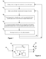
- FIG 1 we present a control quality method according to a particular embodiment of the invention. A part of the method is carried out by a quality control device (the principle of which is described in detail below in relation with figure 5 ).
- a PAM system 10 comprising a network of acoustic sensors, which carries out continuous measurements of acoustic signals.
- the acoustic sensors are arranged along a plurality of streamers towed by a seismic vessel.
- the acoustic sensors 53 are of the following type: hydrophones and/or accelerometers and/or vector sensors (i.e. couples of geophones).
- a remote source 20 adapted to emit test acoustic signals.
- the remote source 20 is a simulator of marine mammal vocalizes, which is immerged at a known location and depth from the PAM system 10.
- the "wave filled" square labeled 30 illustrates the quality control device.
- the PAM system 10, the remote source 20 and the quality control device 30 are necessary to implement the method according to an exemplary embodiment of the invention.
- the quality control device 30 is integrated in the PAM system 10.
- the quality control device 30 is integrated in the source 20.
- the quality control device 30 is independent from the source 20 and the PAM system 10.
- the method according to an exemplary embodiment of the invention is fully automatic and does not require any operators either source side or PAM system side.
- the quality control method is first described below through the particular embodiment of figure 2 .
- the PAM system 10 is master and the source 20 is slave.
- the quality control method is initialized by the device 30, which remotely drives the source 20 from the PAM system 10.
- the source 20 is remote-controlled by the device 30 by means of commands transmitted via wireless communication means, such as a radio frequency link for example.
- step 100 the device 30 transmits an emission command C1 to the source 20 in order to trigger the emission of a test acoustic signal.
- the source 20 Upon reception of the emission command C1, the source 20 emits a test acoustic signal 50 in the surrounding water.
- the device 30 transmits a measurement command C2 to the PAM system 10 in order to trigger the execution of acoustic signal measurements synchronously with the emission of the test acoustic signal 50 by the source 20.
- the emission command C1 is an external command transmitted from the PAM system 10 to the remote source 20, to remotely trigger the emission of the test acoustic signal 50.
- the measurement command C2 is an internal command transmitted from the device 30 to the control unit 15 of PAM system 10, both device 30 and control unit 15 being comprised in the PAM system 10.
- the aim is to synchronize the emission of the test acoustic signal 50 by the source 20 with the acoustic signal measurements carried out by the PAM system 10.
- the synchronous implementation between the test acoustic signal emission and the signal measurements is given here for illustrative purposes only. Other implementations are possible without departing from the scope of the invention. By example, it could be implemented a starting of signal measurements before triggering the test acoustic signal 50, then a resynchronization of the signal measurements in post-processing.
- the test acoustic signal 50 is associated with a set of reference parameters which is characteristic of and/or associated with the test acoustic signal emitted, and notably:
- the reference parameters are defined by the device 30 and stored in its data memory. They enable the device 30 to configure the test acoustic signal 50 to emit.
- test acoustic signal 50 emitted by the source 20 represents a synthetized vocalize of an odontocetes for example whose the characteristics are followings: whistles-shaped signal, medium emission frequencies comprised between 12kHz and 20kHz for simulating a bottlenosed dolphin for instance.
- step 110 the PAM system 10 previously activated by the device 30 obtains acoustic signal measurements of the test acoustic signal 50 emitted by the source 20, by means of the network of acoustic sensors.
- step 120 the PAM system then estimates parameters characteristic of and/or associated with the test acoustic signal 50, as a function of the acoustic signal measurements obtained in step 110, namely:
- step 130 the device 30 first collects the parameters estimated by the PAM system 10 (communication illustrated by the arrow C3), then compares the estimated parameters with the aforesaid set of reference parameters, in order to deduce information on quality of operation of the PAM system 10.
- step 140 the device 30 obtains quality information as a function of results of the comparing step 130.
- the quality information are then sent to the control unit 15 of the PAM system (communication illustrated by the arrow C4).
- This particular embodiment implies establishing, in step 130, an internal communication C3 to enable the device 30 to obtain the parameters estimated by the PAM system 10 from the control unit 15 and, in step 140, an internal communication C4 to enable the device 30 to provide the PAM system 10 with the quality information determined by the device 30 via the control unit 15.
- the quality control device 30 is integrated in the source 20.
- the source 20 is master and the PAM system 10 is slave.
- step 100 the quality control method is initialized by the device 30, which drives the source 20 from the source itself by means of an internal emission command C1 sent to the control unit 25 of the source 20.
- an internal emission command C1 sent to the control unit 25 of the source 20.
- it is an internal command that triggers the emission of a test acoustic signal in step 100.
- the source 20 Upon reception of the internal emission command C1, the source 20 emits a test acoustic signal 50 in the surrounding water.
- the device 30 transmits a measurement command C2 to the control unit 15 of the PAM system 10 in order to remotely trigger the execution of acoustic signal measurements synchronously with the emission of the test acoustic signal 50 by the source 20.
- a measurement command C2 to the control unit 15 of the PAM system 10 in order to remotely trigger the execution of acoustic signal measurements synchronously with the emission of the test acoustic signal 50 by the source 20.
- it is an external command that triggers, in step 100, the acoustic signal measurements of the PAM system 10.
- step 100 consists in triggering the execution of acoustic signal measurements performed by the PAM system 10, by sending a pre-test acoustic signal from the source 20 to the PAM system 10, or by inserting in the test acoustic signal 50 itself, a specific data block or a specific pattern giving instructions to the PAM system 10 to trigger acoustic signal measurements at a given time.
- this particular embodiment implies establishing an external communication C3 between the control unit 15 of the PAM system 10 and the device 30 integrated in the source 20, to enable the device 30 to obtain the parameters estimated by the PAM system 10.
- this particular embodiment implies establishing an external communication C4 between the device 30 integrated in the source 20 and the control unit 15 of the PAM system 10, to enable the device 30 to provide the PAM system 10 with the quality information obtained by the device 30.
- the quality control device 30 is independent from the source 20 and the PAM system 10, and manages the steps 100, 130 and 140 of the method thanks to external commands transmitted between the different entities, via radiocommunication means for example.
- the quality control method is initialized by the device 30, which remotely drives the source 20.
- step 100 the device 30 transmits an external emission command C1 to the control unit 25 of the source 20 in order to trigger the emission of a test acoustic signal.
- the source 20 Upon reception of the emission command C1, the source 20 emits a test acoustic signal 50 in the surrounding water.
- the device 30 transmits an external measurement command C2 to the control unit 15 of the PAM system 10 in order to trigger the execution of acoustic signal measurements synchronously with the emission of the test acoustic signal 50 by the source 20.
- step 130 the device 30 collects the parameters estimated by the PAM system 10 by means of a communication C3 established between the device 30 and the control unit 15 of the PAM system 10, then compares the estimated parameters with the aforesaid reference parameters.
- step 140 the device 30 obtains quality information as a function of results of the comparing step 130 and sent them to the PAM system 10 by means of a communication C4 established between the device 30 and the control unit 15 of the PAM system 10.
- the quality control device 30 can therefore test different characteristics of acoustic signal to evaluate the quality of operation of the PAM system for different characteristics of acoustic signal.
- the quality control device 30 further cooperates with the navigation system to take into account the seismic shooting session implemented by the navigation system (not shown on figures).
- the navigation system trigs the seismic source shots (i.e. airguns shots) and the acoustic positioning system of the streamers.
- the seismic source shots can produce disturbances (masking phenomena) liable to affect the acoustic signal measurements performed by the PAM system 10.
- the device 30 carries out, in step 100, a synchronization of the step of driving the source 20 with the seismic shooting session.
- a seismic shooting session comprises several shooting time slots and several non-shooting time slots, and the synchronization of the step 100 of driving the source 20 is performed such that the test acoustic signal 50 is emitted either during said one of the shooting time slots or during one of the non-shooting time slots.
- the shooting time slots and non-shooting time slots it is possible to identify and characterize abiotic signals (due to seismic apparatus) in the acoustic signal measurements and therefore to characterize accurately the impact of the seismic source shots on the acoustic signals measurements during seismic surveys, which is not possible with prior art methods.
- the synchronization with the seismic shooting session ensures the compatibility between the different acoustic systems (navigation and PAM systems).
- the method allows using the source 20 without interfering with the seismic operations, i.e. the quality control device 30 is able to operate in between two seismic acquisitions driven by the navigation system. In this way, the sensors eventually used for both seismic and PAM purposes would not be affected by any additional sound that would arise from the source 20 while they are acquiring seismic information.
- the method allows using the source 20 without interfering with the acoustic positioning system of the streamers.
- the source 20 can be a marine mammal vocalize simulator, a marine seismic source, a marine depth-sounder, a marine transponder.
- the marine seismic source such as airgun used in marine seismic exploration, depth-sounder and transponder can be diverted from their original use to perform the emission of test acoustic signals, driven by the quality control device 30.
- the vocalize simulator can be installed anywhere on the overall system used for the seismic prospection, i.e. on a vessel, on a head buoy or end-tail buoy (towed, mooring or drifting), on the seismic source network, or integrated on or inside the seismic streamers.
- the location of the source 20 is determined thanks to a positioning system, such as a GPS (Global Positioning System), an AIS (Automatic Identification System) or an acoustic positioning system.
- the vocalize simulator can also be installed on a independent device such as an underwater unmanned vehicle eventually equipped with seismic equipments, an ocean bottom node disposed on the seafloor, or on a dedicated device immerged at known location and depth from the PAM system 10.
- the method described above involves only one given source driven by the control quality device.
- a greater number of sources driven by the control quality device can be used in order to improve the performances of the method according to an exemplary embodiment of the invention, as explained below.
- each source uses a distinct emission frequency range.
- an iteration of the steps 100 to 140 (loop (a) in figure 1 ) is carried out for each of the three sources concerned, the quality control device 30 carrying out the steps 100, 130 and 140 simultaneously for the set of three sources. This enables to execute multiple quality control processes in parallel.
- cetaceans including mysticetes and odontocetes
- the whole sound production of cetaceans includes very low frequencies emissions of mysticetes, medium frequencies emissions of odontocetes (whistles) and high frequencies emissions of odontocetes (clicks).
- the quality control device 30 is also capable of adjusting automatically some of characteristics defining the step 110 of obtaining acoustic signal measurements and the step 120 of estimating parameters by means an optimization process, as described hereafter. This allows taking into account characteristics that may dynamically change in time.
- the optimization process consists here in replaying measurements acquired by the PAM system 10 after having changed at least one characteristic defining said step of estimating. For example, we may adjust automatically Fast Fourier Transform parameters or gain for a specific frequency bandwidth, for each iteration.
- the device 30 carries out false alarm measurement. While the source 20 is turned off, the device 30 takes this opportunity to trigger a step of acoustic signal measurements by the PAM system in order to record the number of false alarms detected per time unit (this number of false alarms is referred as a false alarm probability). This avoids that a non-detection is systematically attributed to a non-emission of a test acoustic signal by the source 20.
- the quality information obtained in step 140 belongs to the group comprising: DCL ("Detection, Classification, Localization") performances. Those information are used notably to calibrate functions of the PAM system 10.
- Figure 5 shows the simplified structure of a quality control device (or a machine) according to a particular embodiment of the invention, which carries out the steps 100, 130 and 140 of method shown in figure 1 .
- This device is comprised for example in the PAM system).
- the device 60 comprises a non-volatile memory 61 (e.g. a read-only memory (ROM) or a hard disk), a volatile memory 63 (e.g. a random access memory or RAM) and a processor 62.
- the non-volatile memory 61 is a non-transitory computer-readable carrier medium. It stores executable program code instructions, which are executed by the processor 62 in order to enable implementation of the quality control method described above in relation with figure 1 .
- the aforementioned program code instructions are transferred from the non-volatile memory 61 to the volatile memory 63 so as to be executed by the processor 62.
- the volatile memory 63 likewise includes registers for storing the variables and parameters required for this execution.
- the device 60 receives as inputs, from the PAM system, estimated parameters 64 characteristic of and/or associated with the test acoustic signal emitted by the source. It generates as outputs quality information 65 as described above.
- the device 60 also generates as outputs an emission command 66 to the source in order to trigger the emission of a test acoustic signal and a measurement command 67 to the PAM system in order to trigger the execution of acoustic signal measurements and to synchronize the measurements with the emission of the test acoustic signal, as described above.
- the invention is not limited to a purely software-based implementation, in the form of computer program instructions, but that it can also be implemented in hardware form or any form combining a hardware portion and a software portion.
Landscapes
- Physics & Mathematics (AREA)
- Life Sciences & Earth Sciences (AREA)
- Acoustics & Sound (AREA)
- Remote Sensing (AREA)
- Engineering & Computer Science (AREA)
- Environmental & Geological Engineering (AREA)
- Geology (AREA)
- General Life Sciences & Earth Sciences (AREA)
- General Physics & Mathematics (AREA)
- Geophysics (AREA)
- Oceanography (AREA)
- Measurement Of Mechanical Vibrations Or Ultrasonic Waves (AREA)
- Testing Of Individual Semiconductor Devices (AREA)
Abstract
Description
- The field of the invention is that of passive acoustic monitoring. It deals with the equipments required in order to respect constraints imposed by regulating agencies which aim to protect marine mammal life.
- More specifically, the invention pertains to a technique for automatically evaluating quality of operation of passive acoustic monitoring system, hereafter called PAM system.
- Underwater passive acoustic monitoring is a non-intrusive technique that can be used to detect, classify and localize (DCL) marine mammals.
- It should be noted that if a PAM system allows to listen and detect acoustics signals of biological origin, it can also listen and detect any undesired sound contribution created by other activities.
- The invention relates to marine seismic survey, but can be of interest for any other field which requires a system performing marine mammal's monitoring in a marine environment.
- It is sought more particularly here below in this document to describe problems existing in the field of geophysical data acquisition for analysing the sea-bed (e.g. for oil exploration industry using seismic prospection method). The invention of course is not limited to this particular field of application but is of interest for any technique for performing quality control of measurements of marine mammal vocalizes that has to cope with closely related or similar issues and problems.
- Regulation agencies encourage or impose the use of a PAM system during seismic survey campaigns. These regulating agencies propose guidelines defining rules to apply during seismic campaigns in order to protect the marine mammals. In particular the guidelines recommend the PAM system to detect the presence of marine mammals in the vicinity of seismic sources, which can be considered as injurious to the marine mammal life (e.g. acoustic disturbances).
- In the prior art, a PAM system typically comprises a network of acoustic sensors, such as hydrophones or geophones or accelerometers or vector sensors, arranged along one or several linear acoustic antennas (hereafter referred to "streamers") towed by a vessel, and adapted for detecting and measuring vocalizes, i.e. acoustic signals emitted by marine mammals. When a marine mammal vocalizes in the vicinity of the network of seismic sensors, these sensors make measurements of the acoustic signal or signals emitted by the marine mammal. A localization computation is then performed from the measurement data collected by the sensors to determine the localization of the marine mammal from the seismic sources.
- There are two known families of PAM systems used by the oil prospecting companies:
- the integrated PAM systems, which rely on the use of a network of seismic sensors distributed on the streamers towed by the seismic vessel, which seismic sensors being originally adapted to perform geophysics data acquisition, and thus diverted of its function first to make passive acoustic monitoring;
- the independent PAM systems, which rely on the use of a network of dedicated acoustic sensors arranged along a linear acoustic line, which is deployed and towed in addition to the existing streamers behind the seismic vessel and entirely dedicated to the passive acoustic monitoring.
- Nowadays, regulating agencies and stakeholders in marine survey operations establish codes of conduct which suggest demonstrating the capabilities of a PAM system to detect, classify and localize the mammal species likely to be encountered in the survey area during the planning phase of a seismic survey.
- The lack of knowledge on the performances of the different devices of a PAM system can reduce the accuracy or usefulness of the collected acoustic data by the sensors. Since seismic surveys can be quite time-consuming, there is a need to evaluating, as the survey progresses, the quality of operation of the PAM system. This is referred hereafter to as "quality control" or "QC".
- Moreover, the guidelines also suggest testing the quality of operation of the towed streamers before each deployment to ensure that no malfunction exists. This simply consists in verifying that the sensors of the towed streamers properly work and are well connected thanks to a so called "tap test", which is done with manually tapping the sensors and verifying they detect such tapping.
- In the prior art, a known method for controlling quality of operation of a PAM system during fieldwork consist in measuring background noise during the seismic survey. At low frequency, the background noise is preponderant on the electronics of components, so measuring the background noise allows checking the integrity of the whole data acquisition chain in the towed streamers, and detecting a possible failure of a sensor.
- However, this known method is carried out irregularly and requires on the assumption that the background noise remains relatively constant during the seismic survey. In addition, opportunity acoustic sources, the vessel noise and the noise caused by the seismic source firing are used to build performance indicators of the acoustic reception chain. However, as none of these sources are accurately characterized (in particular emission level versus frequency), this method only permits to check that the acoustic measurements are globally representatives. This does not therefore provide satisfactory quality information. Lastly, if a sensor were in default from the start of the survey, this one would not be identified by that background noise test.
- In summary, this known method only provides a rough idea of the level of quality of operation of the PAM system.
- Another known method of control of quality of a PAM system is based on the use of a source emitting a test acoustic signal simulating a vocalize of a marine mammal. This source is immerged at a known location and depth. This method of control of quality of a PAM system can be summarized as follow:
- a first operator on the source side triggers the source to emit a test acoustic signal;
- the PAM system obtains acoustic signal measurements;
- a second operator on the PAM system side carries out the following steps:
- * estimates parameters, characteristic of and/or associated with the test acoustic signal, as a function of the obtained acoustic signal measurements;
- * compares the estimated parameter with reference parameters characteristic of and/or associated with the test acoustic signal;
- * obtains at least one piece of quality information, as a function of results of the comparing step.
- The reference parameters belongs to the group comprising:
- characteristics of the test acoustic signal (such as the emission level, the signal shape, the bandwidth, the centre frequency, etc.);
- an emission time of the test acoustic signal; and
- an emission location of the at least one source.
- However, this known method is fastidious, as it requires the presence of an operator on simulator side and an operator on PAM system side, the operators carrying out the different steps of the process manually. This involves the presence of experimented operators, especially on PAM system side where the calculations of quality control are carried out by hand. As data are collected in different locations and different formats, the validation process is further heavy and takes time.
- In addition, owing to the frequency bandwidth used by the seismic sources, such known method is highly sensitive to phenomena of masking of sensors. Indeed, frequency bandwidth of vocalizes emitted by marine mammals can be, at least partially, common with the frequency bandwidth used by the seismic sources. Then, the detection range for a given marine mammal is highly reduced if its vocalizes illuminate the sensors during a seismic shooting session. This masking phenomenon being not taken into consideration in the known method, control quality results are highly variable and therefore not always reliable.
- The invention, in at least one embodiment, is aimed especially at overcoming these different drawbacks of the prior art.
- More specifically, it is a goal of at least one embodiment of the invention to provide a technique for controlling quality of operation of a PAM system, this technique being executed automatically without requiring any operator on source side or on PAM side.
- It is also an aim of at least one embodiment of the invention to provide a technique of this kind that allows real time running during the seismic survey.
- It is another goal of at least one embodiment of the invention to provide a technique of this kind that allows taking into account the real acoustic conditions during the seismic surveys.
- It is another goal of at least one embodiment of the invention to provide a technique of this kind that allows providing high-quality information.
- A particular embodiment of the invention proposes a method for controlling quality of operation of passive acoustic monitoring system, said method comprising, at least for one given source:
- a) said given source emits at least one acoustic test signal;
- b) the passive acoustic monitoring system obtains acoustic signal measurements and estimates at least one parameter, characteristic of and/or associated with said at least one test acoustic signal, as a function of said acoustic signal measurements;
- c) comparing the at least one estimated parameter with at least one reference parameter, characteristic of and/or associated with said at least one test acoustic signal;
- d) obtaining at least one piece of quality information, as a function of results of said comparing step.
- The method is such that a quality control device carries out the following steps:
- 1) drives said given source to trigger said step a);
- 2) obtains said at least one estimated parameter; and
- 3) carries out said steps c) and d).
- Thus an exemplary embodiment of the invention relies on a fully automatic method of controlling quality of operation of a passive acoustic monitoring system, which does not require any operators either source side or PAM system side. To that end, an exemplary embodiment of the invention is based on the implementation of a quality control device responsible for driving at least one given source and synchronizing the at least one given source with the acoustic signal measurements carried out by the PAM system on the one hand, and for carrying out the control of quality of operation of the passive acoustic monitoring system, on the other hand. Said at least one piece of quality information obtained can be then used to calibrate the passive acoustic monitoring system with accuracy.
- According to a particular feature, said quality control device belongs to the group comprising:
- a quality control device integrated in said passive acoustic monitoring system;
- a quality control device integrated in said given source; and
- a quality control device independent of said passive acoustic monitoring system and said given source.
- Thus, an exemplary embodiment of the invention provides for several embodiments in which the quality control device can be integrated either in the passive acoustic monitoring system or in the given source, or in which it can be independent from the passive acoustic monitoring system and given source. In last case, this allows a real time running of the method in an autonomous independent device.
- According to a particularly advantageous feature, a navigation system implements a seismic shooting session, and said quality control device carries out a synchronization of said step of driving the given source, with said seismic shooting session.
- The seismic source shots during survey produces disturbances (masking phenomena) liable to affect the acoustic signals measurements performed by the PAM system. By taking into account the seismic shooting session, it is thus possible to identify and characterize abiotic signals (due to seismic apparatus) in the acoustic signal measurements and thereby to take them into consideration in the step of estimating parameters. As a consequence, the quality information obtained according to an exemplary embodiment of the invention are more reliable than the quality information obtained by the prior art methods.
- According to a particular feature, the seismic shooting session comprises at least one shooting time slot and at least one non-shooting time slot, and wherein said synchronization of said step of driving the given source, with said seismic shooting session, is such that said at least one test acoustic signal is emitted either during said at least one shooting time slot or during said at least one non-shooting time slot.
- The interest to have a piece of information during a shooting time slot and a piece of information during a non-shooting time slot is that it enables the quality control device to characterize accurately the impact of the seismic source shots on the acoustic signals measurements during seismic surveys.
- According to a particular feature, an iteration of said steps a) to d) is carried out for each of at least two sources, each source is located in a distinct location, and said quality control device carries out said steps 1) to 3) for each of said at least two sources.
- As the reception radiation pattern of the PAM system is not homogenous, an astute choice of location of the different sources as a function of the reception radiation pattern can be carried out in the control quality process, in order to enhance the functioning of the PAM system. Indeed, in practice, certain areas of the sensing coverage of sensors are more or less sensitive (due to the radiation pattern and the geographic configuration of the network of sensors in the PAM system).
- According to a variant, an iteration of said steps a) to d) is carried out for each of at least two sources, each source using a distinct emission frequency range, and said quality control device carries out, simultaneously for said at least two sources, said steps 1) to 3).
- This enables to execute multiple quality control processes in parallel.
- According to a particular feature, said given source belongs to the group comprising:
- a marine mammal vocalize simulator;
- a marine seismic source;
- a marine depth-sounder; and
- a marine transponder.
- The marine seismic source (such as an airgun or water-gun used in marine seismic exploration), depth-sounder and transponder can be diverted from their original use to perform the emission of test acoustic signal, driven by the quality control device.
- The given source, as function of its nature, can be installed anywhere on the overall system used for the seismic prospection, i.e. on a vessel, on a head buoy or end-tail buoy (towed, mooring or drifting), on the seismic source network, or integrated on or inside the seismic streamers. The vocalize simulator can be installed on an independent device such as an underwater unmanned vehicle eventually equipped with seismic equipments, an ocean bottom node disposed on the seafloor, or on a dedicated device immerged at known location and depth from the PAM system.
- According to a particular feature, said at least one reference parameter belongs to the group comprising:
- characteristics of said at least one test acoustic signal;
- an emission time of said at least one test acoustic signal; and
- an emission location of said at least one source.
- The characteristics of said at least one test acoustic signal comprises notably the signal shape (e.g. to simulate whistle, clicks, train clicks, moan), the emission level, the emission frequencies range, the central frequency, the emission duration.
- According to a particular feature, at least two iterations of said steps a) to d) and said steps 1) to 3) are carried out for said given source, with at least one characteristic of said at least one test acoustic signal which is different for each iteration.
- This enables the quality control device to test different characteristics of acoustic signal and therefore to evaluate the quality of operation of the PAM system for different characteristics of acoustic signal.
- According to a particularly advantageous variant, at least two iterations of said steps a) to d) and said steps 1) to 3) are carried out for said given source, with at least one characteristic defining said step of obtaining acoustic signal measurements which is different for each iteration.
- The quality control device adjusts automatically some of characteristics defining said step of obtaining acoustic signal measurements by means an optimization process.
- According to a particularly advantageous feature, at least two iterations of said steps b) to d) and said steps 2) to 3) are carried out for said given source, with at least one characteristic defining said step of estimating which is different for each iteration.
- The quality control device adjusts automatically some of characteristics defining said step of estimating by means an optimization process, which consists here in replaying measurements acquired by the PAM system after having changed at least one characteristic defining said step of estimating.
- In another embodiment, the invention pertains to a computer program product comprising program code instructions for implementing the above-mentioned method (in any of its different embodiments) when said program is executed on a computer or a processor.
- In another embodiment, the invention pertains to a non-transitory computer-readable carrier medium, storing a program which, when executed by a computer or a processor causes the computer or the processor to carry out the above-mentioned method (in any of its different embodiments).
- In another embodiment, the invention pertains to a quality control device adapted to control quality of operation of a passive acoustic monitoring system (10), characterized in that it comprises:
- means for driving a given source to trigger emission of at least one acoustic test signal by said given source;
- means for obtaining at least one parameter, characteristic of and/or associated with said at least one test acoustic signal, estimated by the passive acoustic monitoring system as a function of acoustic signal measurements obtained by the passive acoustic monitoring system;
- means for comparing the at least one estimated parameter with at least one reference parameter, characteristic of and/or associated with said at least one test acoustic signal;
- means for obtaining at least one piece of quality information, as a function of results delivered by said comparing means.
- Advantageously, the quality control device comprises means for implementing the steps it performs in the quality control process as described above, in any of its various embodiments.
- Other features and advantages of embodiments of the invention shall appear from the following description, given by way of an indicative and non-exhaustive examples and from the appended drawings, of which:
-
Figure 1 is a flowchart of a particular embodiment of the method according to the invention; -
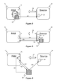
Figure 2 represents a schematic illustration of the principle of functioning of the method according to a first embodiment of the invention; -
Figure 3 represents a schematic illustration of the principle of functioning of the method according to a second embodiment of the invention; -
Figure 4 represents a schematic illustration of the principle of functioning of the method according to a third embodiment of the invention; -
Figure 5 shows the simplified structure of a quality control device according to a particular embodiment of the invention. - In all of the figures of the present document, identical elements and steps are designated by the same numerical reference sign.
- In the example described below, we consider the control of quality of operation of a PAM system in the context of a sea oil survey.
- Referring now to
figure 1 , we present a control quality method according to a particular embodiment of the invention. A part of the method is carried out by a quality control device (the principle of which is described in detail below in relation withfigure 5 ). - As illustrated on
figures 2 to 4 , we consider aPAM system 10 comprising a network of acoustic sensors, which carries out continuous measurements of acoustic signals. The acoustic sensors are arranged along a plurality of streamers towed by a seismic vessel. The acoustic sensors 53 are of the following type: hydrophones and/or accelerometers and/or vector sensors (i.e. couples of geophones). We also consider aremote source 20 adapted to emit test acoustic signals. In the present example, theremote source 20 is a simulator of marine mammal vocalizes, which is immerged at a known location and depth from thePAM system 10. The "wave filled" square labeled 30 illustrates the quality control device. ThePAM system 10, theremote source 20 and thequality control device 30 are necessary to implement the method according to an exemplary embodiment of the invention. - In
figure 2 (first embodiment), thequality control device 30 is integrated in thePAM system 10. Infigure 3 (second embodiment), thequality control device 30 is integrated in thesource 20. Infigure 4 (third embodiment), thequality control device 30 is independent from thesource 20 and thePAM system 10. - The method according to an exemplary embodiment of the invention is fully automatic and does not require any operators either source side or PAM system side.
- The quality control method is first described below through the particular embodiment of
figure 2 . In that particular embodiment, thePAM system 10 is master and thesource 20 is slave. - The quality control method is initialized by the
device 30, which remotely drives thesource 20 from thePAM system 10. Thesource 20 is remote-controlled by thedevice 30 by means of commands transmitted via wireless communication means, such as a radio frequency link for example. - In
step 100, thedevice 30 transmits an emission command C1 to thesource 20 in order to trigger the emission of a test acoustic signal. Upon reception of the emission command C1, thesource 20 emits a testacoustic signal 50 in the surrounding water. - At the same time, the
device 30 transmits a measurement command C2 to thePAM system 10 in order to trigger the execution of acoustic signal measurements synchronously with the emission of the testacoustic signal 50 by thesource 20. - In this particular embodiment, the emission command C1 is an external command transmitted from the
PAM system 10 to theremote source 20, to remotely trigger the emission of the testacoustic signal 50. The measurement command C2 is an internal command transmitted from thedevice 30 to thecontrol unit 15 ofPAM system 10, bothdevice 30 andcontrol unit 15 being comprised in thePAM system 10. - The aim is to synchronize the emission of the test
acoustic signal 50 by thesource 20 with the acoustic signal measurements carried out by thePAM system 10. The synchronous implementation between the test acoustic signal emission and the signal measurements is given here for illustrative purposes only. Other implementations are possible without departing from the scope of the invention. By example, it could be implemented a starting of signal measurements before triggering the testacoustic signal 50, then a resynchronization of the signal measurements in post-processing. - The test
acoustic signal 50 is associated with a set of reference parameters which is characteristic of and/or associated with the test acoustic signal emitted, and notably: - reference characteristics of the test
acoustic signal 50, such as the emission level, the signal shape, the bandwidth, the centre frequency, etc.; - a emission time of the test
acoustic signal 50; and - a emission location of the
source 20. - The reference parameters are defined by the
device 30 and stored in its data memory. They enable thedevice 30 to configure the testacoustic signal 50 to emit. - By way of illustration, the test
acoustic signal 50 emitted by thesource 20 represents a synthetized vocalize of an odontocetes for example whose the characteristics are followings: whistles-shaped signal, medium emission frequencies comprised between 12kHz and 20kHz for simulating a bottlenosed dolphin for instance. - In
step 110, thePAM system 10 previously activated by thedevice 30 obtains acoustic signal measurements of the testacoustic signal 50 emitted by thesource 20, by means of the network of acoustic sensors. - In
step 120, the PAM system then estimates parameters characteristic of and/or associated with the testacoustic signal 50, as a function of the acoustic signal measurements obtained instep 110, namely: - estimated characteristics of the test
acoustic signal 50, such as the emission level, the signal shape, the bandwidth, the central frequency, etc.; - estimated emission time of the test
acoustic signal 50; and - estimated emission location of the
source 20. - In
step 130, thedevice 30 first collects the parameters estimated by the PAM system 10 (communication illustrated by the arrow C3), then compares the estimated parameters with the aforesaid set of reference parameters, in order to deduce information on quality of operation of thePAM system 10. - In
step 140, thedevice 30 obtains quality information as a function of results of the comparingstep 130. The quality information are then sent to thecontrol unit 15 of the PAM system (communication illustrated by the arrow C4). - This particular embodiment implies establishing, in
step 130, an internal communication C3 to enable thedevice 30 to obtain the parameters estimated by thePAM system 10 from thecontrol unit 15 and, instep 140, an internal communication C4 to enable thedevice 30 to provide thePAM system 10 with the quality information determined by thedevice 30 via thecontrol unit 15. - In that particular embodiment, the
quality control device 30 is integrated in thesource 20. Thesource 20 is master and thePAM system 10 is slave. - In
step 100, the quality control method is initialized by thedevice 30, which drives thesource 20 from the source itself by means of an internal emission command C1 sent to thecontrol unit 25 of thesource 20. Thus, contrary to the first embodiment, it is an internal command that triggers the emission of a test acoustic signal instep 100. Upon reception of the internal emission command C1, thesource 20 emits a testacoustic signal 50 in the surrounding water. - In parallel, the
device 30 transmits a measurement command C2 to thecontrol unit 15 of thePAM system 10 in order to remotely trigger the execution of acoustic signal measurements synchronously with the emission of the testacoustic signal 50 by thesource 20. Thus, contrary to the first embodiment, it is an external command that triggers, instep 100, the acoustic signal measurements of thePAM system 10. - A variant of this embodiment, in
step 100, consists in triggering the execution of acoustic signal measurements performed by thePAM system 10, by sending a pre-test acoustic signal from thesource 20 to thePAM system 10, or by inserting in the testacoustic signal 50 itself, a specific data block or a specific pattern giving instructions to thePAM system 10 to trigger acoustic signal measurements at a given time. - In
step 130, this particular embodiment implies establishing an external communication C3 between thecontrol unit 15 of thePAM system 10 and thedevice 30 integrated in thesource 20, to enable thedevice 30 to obtain the parameters estimated by thePAM system 10. - In
step 140, this particular embodiment implies establishing an external communication C4 between thedevice 30 integrated in thesource 20 and thecontrol unit 15 of thePAM system 10, to enable thedevice 30 to provide thePAM system 10 with the quality information obtained by thedevice 30. - In that particular embodiment (
figure 4 ), thequality control device 30 is independent from thesource 20 and thePAM system 10, and manages thesteps - The quality control method is initialized by the
device 30, which remotely drives thesource 20. - In
step 100, thedevice 30 transmits an external emission command C1 to thecontrol unit 25 of thesource 20 in order to trigger the emission of a test acoustic signal. Upon reception of the emission command C1, thesource 20 emits a testacoustic signal 50 in the surrounding water. - In parallel, the
device 30 transmits an external measurement command C2 to thecontrol unit 15 of thePAM system 10 in order to trigger the execution of acoustic signal measurements synchronously with the emission of the testacoustic signal 50 by thesource 20. - In
step 130, thedevice 30 collects the parameters estimated by thePAM system 10 by means of a communication C3 established between thedevice 30 and thecontrol unit 15 of thePAM system 10, then compares the estimated parameters with the aforesaid reference parameters. - In
step 140, thedevice 30 obtains quality information as a function of results of the comparingstep 130 and sent them to thePAM system 10 by means of a communication C4 established between thedevice 30 and thecontrol unit 15 of thePAM system 10. - According to a particular feature of an exemplary embodiment of the invention, we may envisage that several iterations of the
steps 100 to 140 (loop (a) infigure 1 ) are carried out for thesource 20, with characteristics of the test acoustic signal which are different for each iteration. Thequality control device 30 can therefore test different characteristics of acoustic signal to evaluate the quality of operation of the PAM system for different characteristics of acoustic signal. - According to a particularly advantageous feature of an exemplary embodiment of the invention, the
quality control device 30 further cooperates with the navigation system to take into account the seismic shooting session implemented by the navigation system (not shown on figures). The navigation system trigs the seismic source shots (i.e. airguns shots) and the acoustic positioning system of the streamers. During seismic survey, the seismic source shots can produce disturbances (masking phenomena) liable to affect the acoustic signal measurements performed by thePAM system 10. To that end, thedevice 30 carries out, instep 100, a synchronization of the step of driving thesource 20 with the seismic shooting session. More particularly a seismic shooting session comprises several shooting time slots and several non-shooting time slots, and the synchronization of thestep 100 of driving thesource 20 is performed such that the testacoustic signal 50 is emitted either during said one of the shooting time slots or during one of the non-shooting time slots. By taking into account the shooting time slots and non-shooting time slots, it is possible to identify and characterize abiotic signals (due to seismic apparatus) in the acoustic signal measurements and therefore to characterize accurately the impact of the seismic source shots on the acoustic signals measurements during seismic surveys, which is not possible with prior art methods. - Moreover, as the bandwidth of the emitted signals by the
source 20 is important (e.g. from hundred of hertz to hundred of kilohertz), the synchronization with the seismic shooting session ensures the compatibility between the different acoustic systems (navigation and PAM systems). Indeed, the method allows using thesource 20 without interfering with the seismic operations, i.e. thequality control device 30 is able to operate in between two seismic acquisitions driven by the navigation system. In this way, the sensors eventually used for both seismic and PAM purposes would not be affected by any additional sound that would arise from thesource 20 while they are acquiring seismic information. Thus, the method allows using thesource 20 without interfering with the acoustic positioning system of the streamers. - The
source 20 can be a marine mammal vocalize simulator, a marine seismic source, a marine depth-sounder, a marine transponder. The marine seismic source, such as airgun used in marine seismic exploration, depth-sounder and transponder can be diverted from their original use to perform the emission of test acoustic signals, driven by thequality control device 30. - The vocalize simulator can be installed anywhere on the overall system used for the seismic prospection, i.e. on a vessel, on a head buoy or end-tail buoy (towed, mooring or drifting), on the seismic source network, or integrated on or inside the seismic streamers. The location of the
source 20 is determined thanks to a positioning system, such as a GPS (Global Positioning System), an AIS (Automatic Identification System) or an acoustic positioning system. The vocalize simulator can also be installed on a independent device such as an underwater unmanned vehicle eventually equipped with seismic equipments, an ocean bottom node disposed on the seafloor, or on a dedicated device immerged at known location and depth from thePAM system 10. - For the purposes of pedagogical description, the method described above involves only one given source driven by the control quality device. Of course, a greater number of sources driven by the control quality device can be used in order to improve the performances of the method according to an exemplary embodiment of the invention, as explained below.
- Let us take a set of three sources for example, each source being located in a distinct location and emitting a test acoustic signal. An iteration of the
steps 100 to 140 (loop (a) infigure 1 ) is carried out for each of the three sources concerned, thequality control device 30 carrying out thesteps PAM system 10 can be thus carried out in order to enhance the control of quality of operation of thePAM system 10. - According to another particularity of an exemplary embodiment of the invention, each source uses a distinct emission frequency range. In that case, an iteration of the
steps 100 to 140 (loop (a) infigure 1 ) is carried out for each of the three sources concerned, thequality control device 30 carrying out thesteps - It should be noted that for marine mammals, especially cetaceans (including mysticetes and odontocetes), the sound production can be notably identified as a function of emission frequencies. The whole sound production of cetaceans includes very low frequencies emissions of mysticetes, medium frequencies emissions of odontocetes (whistles) and high frequencies emissions of odontocetes (clicks). Thus, by emitting at the same time different test acoustic signals each simulating for example a vocalize in a distinct frequency range, it is possible to implement the method more efficiently.
- The
quality control device 30 according to an exemplary embodiment of the invention is also capable of adjusting automatically some of characteristics defining thestep 110 of obtaining acoustic signal measurements and thestep 120 of estimating parameters by means an optimization process, as described hereafter. This allows taking into account characteristics that may dynamically change in time. - To optimize parameters of the PAM system, we may envisage for example to execute several iterations of the
steps 100 to 140 (loop (a) infigure 1 ) for thesource 20, with at least one characteristic defining saidstep 110 of obtaining acoustic signal measurements which is different for each iteration. For example, we may adjust automatically Fast Fourier Transform parameters or gain for different frequency bandwidth, for each iteration. - To optimize parameters of the PAM system, we may also envisage for example to execute several iterations of the
steps 110 to 140 (loop (b) infigure 1 ) for thesource 20, with at least one characteristic defining saidstep 120 of estimating which is different for each iteration. The optimization process consists here in replaying measurements acquired by thePAM system 10 after having changed at least one characteristic defining said step of estimating. For example, we may adjust automatically Fast Fourier Transform parameters or gain for a specific frequency bandwidth, for each iteration. - In addition, we may envisage that the
device 30 carries out false alarm measurement. While thesource 20 is turned off, thedevice 30 takes this opportunity to trigger a step of acoustic signal measurements by the PAM system in order to record the number of false alarms detected per time unit (this number of false alarms is referred as a false alarm probability). This avoids that a non-detection is systematically attributed to a non-emission of a test acoustic signal by thesource 20. - The quality information obtained in
step 140 belongs to the group comprising: DCL ("Detection, Classification, Localization") performances. Those information are used notably to calibrate functions of thePAM system 10. - The method according to an exemplary embodiment of the invention allows determining notably:
- for the detection function:
- o the false alarm probability (per sensor, per group of sensors or globally for the network of sensors);
- o the detection probability as a function of the distance (or "offset") between the seismic source shot and the test acoustic signal, of the emission source distance, of the characteristics of test acoustic signal;
- for the localization function:
- o the bearing accuracy and precision as a function of the offset between the seismic source shot and the test acoustic signal, of the emission source distance, of the characteristics of test acoustic signal;
- o the range accuracy and precision as a function of the offset between the seismic source shot and the test acoustic signal, of the emission source distance, of the characteristics of test acoustic signal;
- o The location uncertainty accuracy and precision as a function of the offset between the seismic source shot and the test acoustic signal, of the emission source distance, of the characteristics of test acoustic signal.
-
Figure 5 shows the simplified structure of a quality control device (or a machine) according to a particular embodiment of the invention, which carries out thesteps figure 1 . This device is comprised for example in the PAM system). - The
device 60 comprises a non-volatile memory 61 (e.g. a read-only memory (ROM) or a hard disk), a volatile memory 63 (e.g. a random access memory or RAM) and aprocessor 62. Thenon-volatile memory 61 is a non-transitory computer-readable carrier medium. It stores executable program code instructions, which are executed by theprocessor 62 in order to enable implementation of the quality control method described above in relation withfigure 1 . - Upon initialization, the aforementioned program code instructions are transferred from the
non-volatile memory 61 to thevolatile memory 63 so as to be executed by theprocessor 62. Thevolatile memory 63 likewise includes registers for storing the variables and parameters required for this execution. - The
device 60 receives as inputs, from the PAM system, estimatedparameters 64 characteristic of and/or associated with the test acoustic signal emitted by the source. It generates asoutputs quality information 65 as described above. - The
device 60 also generates as outputs anemission command 66 to the source in order to trigger the emission of a test acoustic signal and ameasurement command 67 to the PAM system in order to trigger the execution of acoustic signal measurements and to synchronize the measurements with the emission of the test acoustic signal, as described above. - All the steps of the above steering method can be implemented equally well:
- by the execution of a set of program code instructions executed by a reprogrammable computing machine such as a PC type apparatus, a DSP (digital signal processor) or a microcontroller. This program code instructions can be stored in a non-transitory computer-readable carrier medium that is detachable (for example a floppy disk, a CD-ROM or a DVD-ROM) or non-detachable; or
- by a dedicated machine or component, such as an FPGA (Field Programmable Gate Array), an ASIC (Application-Specific Integrated Circuit) or any dedicated hardware component.
- In other words, the invention is not limited to a purely software-based implementation, in the form of computer program instructions, but that it can also be implemented in hardware form or any form combining a hardware portion and a software portion.
- Although the present disclosure has been described with reference to one or more examples, workers skilled in the art will recognize that changes may be made in form and detail without departing from the scope of the disclosure and/or the appended claims.
Claims (14)
- Method for controlling quality of operation of a passive acoustic monitoring system (10), said method comprising, at least for one given source (20):a) said given source emits at least one acoustic test signal;b) the passive acoustic monitoring system obtains acoustic signal measurements and estimates at least one parameter, characteristic of and/or associated with said at least one test acoustic signal, as a function of said acoustic signal measurements;c) comparing the at least one estimated parameter with at least one reference parameter, characteristic of and/or associated with said at least one test acoustic signal;d) obtaining at least one piece of quality information, as a function of results of said comparing step; and
characterized in that a quality control device (30) performs:1) driving said given source to trigger said step a);2) obtaining said at least one estimated parameter; and3) carrying-out said steps c) and d). - Method according to claim 1, wherein said quality control device belongs to the group consisting of:- a quality control device integrated in said passive acoustic monitoring system;- a quality control device integrated in said given source; and- a quality control device independent of said passive acoustic monitoring system and said given source.
- Method according to any one of the claims 1 to 2, wherein a navigation system implements a seismic shooting session, and wherein said quality control device carries out a synchronization of said step of driving the given source, with said seismic shooting session.
- Method according to claim 3, wherein the seismic shooting session comprises at least one shooting time slot and at least one non-shooting time slot, and wherein said synchronization of said step of driving the given source, with said seismic shooting session, is such that said at least one test acoustic signal is emitted either during said at least one shooting time slot or during said at least one non-shooting time slot.
- Method according to any one of the claims 1 to 4, wherein an iteration of said steps a) to d) is carried out for each of at least two sources, each source being located in a distinct location, and wherein said quality control device carries out said steps 1) to 3) for each of said at least two sources.
- Method according to any one of the claims 1 to 4, an iteration of said steps a) to d) being carried out for each of at least two sources, each source using a distinct emission frequency range, and wherein said quality control device carries out, simultaneously for said at least two sources, said steps 1) to 3).
- Method according to any one of the claims 1 to 6, wherein said given source belongs to the group consisting of:- a marine mammal vocalize simulator;- a marine seismic source;- a marine depth-sounder; and- a marine transponder.
- Method according to any one of the claims 1 to 7, wherein said at least one reference parameter belongs to the group consisting of:- characteristics of said at least one test acoustic signal;- an emission time of said at least one test acoustic signal; and- an emission location of said at least one source.
- Method according to any one of the claims 1 to 8, wherein at least two iterations of said steps a) to d) and said steps 1) to 3) are carried out for said given source, with at least one characteristic of said at least one test acoustic signal which is different for each iteration.
- Method according to any one of the claims 1 to 8, wherein at least two iterations of said steps a) to d) and said steps 1) to 3) are carried out for said given source, with at least one characteristic defining said step of obtaining acoustic signal measurements which is different for each iteration.
- Method according to any one of the claims 1 to 9, wherein at least two iterations of said steps b) to d) and said steps 2) to 3) are carried out for said given source, with at least one characteristic defining said step of estimating which is different for each iteration.
- Computer program product, characterized in that it comprises program code instructions for implementing the method according to at least one of the claims 1 to 11, when said program is executed on a computer or a processor.
- Non-transitory computer-readable carrier medium storing a computer program product according to claim 12.
- Quality control device (30) adapted to control quality of operation of a passive acoustic monitoring system (10), characterized in that it comprises:- means for driving a given source (20) to trigger emission of at least one acoustic test signal by said given source;- means for obtaining at least one parameter, characteristic of and/or associated with said at least one test acoustic signal, estimated by the passive acoustic monitoring system as a function of acoustic signal measurements obtained by the passive acoustic monitoring system;- means for comparing the at least one estimated parameter with at least one reference parameter, characteristic of and/or associated with said at least one test acoustic signal; and- means for obtaining at least one piece of quality information, as a function of results delivered by said comparing means.
Applications Claiming Priority (2)
| Application Number | Priority Date | Filing Date | Title |
|---|---|---|---|
| US201461951873P | 2014-03-12 | 2014-03-12 | |
| US14/474,741 US9557428B2 (en) | 2014-03-12 | 2014-09-02 | Method for controlling quality of operation of a PAM system, corresponding computer program product, non-transitory computer-readable carrier medium and quality control device |
Publications (3)
| Publication Number | Publication Date |
|---|---|
| EP2930542A2 true EP2930542A2 (en) | 2015-10-14 |
| EP2930542A3 EP2930542A3 (en) | 2016-02-17 |
| EP2930542B1 EP2930542B1 (en) | 2021-11-24 |
Family
ID=52577701
Family Applications (1)
| Application Number | Title | Priority Date | Filing Date |
|---|---|---|---|
| EP15156339.2A Not-in-force EP2930542B1 (en) | 2014-03-12 | 2015-02-24 | Method for controlling quality of operation of a pam system, corresponding computer program product, non-transitory computer-readable carrier medium and quality control device |
Country Status (4)
| Country | Link |
|---|---|
| US (1) | US9557428B2 (en) |
| EP (1) | EP2930542B1 (en) |
| BR (1) | BR102015005403B1 (en) |
| CA (1) | CA2883109C (en) |
Families Citing this family (4)
| Publication number | Priority date | Publication date | Assignee | Title |
|---|---|---|---|---|
| US9625592B2 (en) * | 2014-03-12 | 2017-04-18 | Sercel | Method for localizing a marine mammal in an underwater environment implemented by a PAM system, corresponding device, computer program product and non-transitory computer-readable carrier medium |
| EP3218745A1 (en) * | 2014-11-11 | 2017-09-20 | Exxonmobil Upstream Research Company | Cable head marine seismic source |
| AU2019275488B2 (en) | 2018-05-23 | 2022-03-03 | Bp Exploration Operating Company Limited | An autonomous data acquisition system and method |
| CN118246154B (en) * | 2024-05-28 | 2024-08-20 | 中国人民解放军海军工程大学 | Design method of high overload testing device based on demand decomposition |
Family Cites Families (10)
| Publication number | Priority date | Publication date | Assignee | Title |
|---|---|---|---|---|
| US4509151A (en) | 1982-01-22 | 1985-04-02 | Sea World, Inc. | Marine acoustic analysis system and method |
| NO951668L (en) | 1995-04-28 | 1996-10-29 | Arve Gustavsen | Operating calibration of listening equipment |
| US20050278158A1 (en) | 2003-10-29 | 2005-12-15 | Ellison William T | Method for modeling the effect of a stimulus on an environment |
| FR2920545B1 (en) | 2007-09-03 | 2011-06-10 | Univ Sud Toulon Var | METHOD FOR THE MULTIPLE CHARACTEROGRAPHY OF CETACEANS BY PASSIVE ACOUSTICS |
| FR2929713B1 (en) | 2008-04-02 | 2011-01-28 | Sercel Rech Const Elect | SYSTEM FOR ACQUIRING SEISMIC DATA IN THE MARINE ENVIRONMENT, USING SEISMIC FLUTES COUPLED WITH MEANS FOR DETECTION AND / OR LOCATION OF MARINE MAMMALS. |
| US7974151B2 (en) | 2008-09-17 | 2011-07-05 | Westerngeco L.L.C. | Cetacean protection system |
| US20100278010A1 (en) | 2009-05-01 | 2010-11-04 | Dennis Gubin | Method and system for passive acoustic monitoring in seismic survey operations |
| US8947973B2 (en) | 2010-11-17 | 2015-02-03 | WesternGeco L.L.P. | Active detection of marine mammals during seismic surveying |
| EP2546680B1 (en) | 2011-07-13 | 2014-06-04 | Sercel | Method and device for automatically detecting marine animals |
| EP2568308A1 (en) | 2011-09-09 | 2013-03-13 | Nederlandse Organisatie voor toegepast- natuurwetenschappelijk onderzoek TNO | An acoustic monitoring system and a method of acoustic monitoring |
-
2014
- 2014-09-02 US US14/474,741 patent/US9557428B2/en not_active Expired - Fee Related
-
2015
- 2015-02-24 EP EP15156339.2A patent/EP2930542B1/en not_active Not-in-force
- 2015-02-25 CA CA2883109A patent/CA2883109C/en active Active
- 2015-03-11 BR BR102015005403-3A patent/BR102015005403B1/en not_active IP Right Cessation
Non-Patent Citations (1)
| Title |
|---|
| None |
Also Published As
| Publication number | Publication date |
|---|---|
| US20150260861A1 (en) | 2015-09-17 |
| US9557428B2 (en) | 2017-01-31 |
| BR102015005403A2 (en) | 2017-11-28 |
| BR102015005403B1 (en) | 2021-09-21 |
| CA2883109A1 (en) | 2015-09-12 |
| EP2930542B1 (en) | 2021-11-24 |
| CA2883109C (en) | 2023-08-08 |
| EP2930542A3 (en) | 2016-02-17 |
Similar Documents
| Publication | Publication Date | Title |
|---|---|---|
| CA2736742C (en) | Cetacean protection system | |
| US20120087207A1 (en) | Processing seismic data | |
| AU2015289607B2 (en) | Marine seismic surveying including direct far field measurements | |
| CA2883109C (en) | Method for controlling quality of operation of a pam system, corresponding computer program product, non-transitory computer-readable carrier medium and quality control device | |
| EP2607920A1 (en) | Method and device for estimating an inter-node distance between nodes arranged along towed acoustic linear antennas. | |
| US10094940B2 (en) | Method for localizing a marine mammal in an underwater environment implemented by a PAM system, corresponding device, computer program product and non-transitory computer-readable carrier medium | |
| US9759828B2 (en) | Determining a streamer position | |
| US20140297190A1 (en) | Monitoring of source signature directivity in seismic systems | |
| AU2023201435A1 (en) | Dynamic gain adjustments in seismic surveys | |
| JP7380891B2 (en) | Unidentified sound extraction device and unidentified sound extraction method | |
| CA2883062C (en) | Method for localizing a marine mammal in an underwater environment implemented by a pam system, corresponding device, computer program product and non-transitory computer-readable carrier medium | |
| US9632196B2 (en) | Method and device for estimating a relative position between towed acoustic linear antennas | |
| US11852770B2 (en) | Targeted activation parameters for marine seismic sources | |
| GB2590164A (en) | Targeted activation parameters for marine seismic sources | |
| Grønaas | Experiences from Using WhaleWatcher™, a Marine Mammal Monitoring System Based on Single Sensor Seismic Streamers |
Legal Events
| Date | Code | Title | Description |
|---|---|---|---|
| PUAI | Public reference made under article 153(3) epc to a published international application that has entered the european phase |
Free format text: ORIGINAL CODE: 0009012 |
|
| AK | Designated contracting states |
Kind code of ref document: A2 Designated state(s): AL AT BE BG CH CY CZ DE DK EE ES FI FR GB GR HR HU IE IS IT LI LT LU LV MC MK MT NL NO PL PT RO RS SE SI SK SM TR |
|
| AX | Request for extension of the european patent |
Extension state: BA ME |
|
| PUAL | Search report despatched |
Free format text: ORIGINAL CODE: 0009013 |
|
| AK | Designated contracting states |
Kind code of ref document: A3 Designated state(s): AL AT BE BG CH CY CZ DE DK EE ES FI FR GB GR HR HU IE IS IT LI LT LU LV MC MK MT NL NO PL PT RO RS SE SI SK SM TR |
|
| AX | Request for extension of the european patent |
Extension state: BA ME |
|
| RIC1 | Information provided on ipc code assigned before grant |
Ipc: G01V 1/00 20060101AFI20160112BHEP Ipc: G01V 1/38 20060101ALN20160112BHEP |
|
| 17P | Request for examination filed |
Effective date: 20160728 |
|
| RBV | Designated contracting states (corrected) |
Designated state(s): AL AT BE BG CH CY CZ DE DK EE ES FI FR GB GR HR HU IE IS IT LI LT LU LV MC MK MT NL NO PL PT RO RS SE SI SK SM TR |
|
| STAA | Information on the status of an ep patent application or granted ep patent |
Free format text: STATUS: EXAMINATION IS IN PROGRESS |
|
| 17Q | First examination report despatched |
Effective date: 20181205 |
|
| RIC1 | Information provided on ipc code assigned before grant |
Ipc: G01V 1/00 20060101AFI20190430BHEP Ipc: G01V 1/38 20060101ALN20190430BHEP |
|
| RIC1 | Information provided on ipc code assigned before grant |
Ipc: G01V 1/00 20060101AFI20210318BHEP Ipc: G01V 1/38 20060101ALN20210318BHEP |
|
| RIC1 | Information provided on ipc code assigned before grant |
Ipc: G01V 1/00 20060101AFI20210412BHEP Ipc: G01V 1/38 20060101ALN20210412BHEP |
|
| RIC1 | Information provided on ipc code assigned before grant |
Ipc: G01V 1/00 20060101AFI20210428BHEP Ipc: G01V 1/38 20060101ALN20210428BHEP |
|
| REG | Reference to a national code |
Ref country code: DE Ref legal event code: R079 Ref document number: 602015075183 Country of ref document: DE Free format text: PREVIOUS MAIN CLASS: G01V0001380000 Ipc: G01V0001000000 |
|
| RIC1 | Information provided on ipc code assigned before grant |
Ipc: G01V 1/00 20060101AFI20210607BHEP Ipc: G01V 1/38 20060101ALN20210607BHEP |
|
| GRAP | Despatch of communication of intention to grant a patent |
Free format text: ORIGINAL CODE: EPIDOSNIGR1 |
|
| STAA | Information on the status of an ep patent application or granted ep patent |
Free format text: STATUS: GRANT OF PATENT IS INTENDED |
|
| RIC1 | Information provided on ipc code assigned before grant |
Ipc: G01V 1/00 20060101AFI20210713BHEP Ipc: G01V 1/38 20060101ALN20210713BHEP |
|
| INTG | Intention to grant announced |
Effective date: 20210802 |
|
| GRAA | (expected) grant |
Free format text: ORIGINAL CODE: 0009210 |
|
| STAA | Information on the status of an ep patent application or granted ep patent |
Free format text: STATUS: THE PATENT HAS BEEN GRANTED |
|
| GRAS | Grant fee paid |
Free format text: ORIGINAL CODE: EPIDOSNIGR3 |
|
| AK | Designated contracting states |
Kind code of ref document: B1 Designated state(s): AL AT BE BG CH CY CZ DE DK EE ES FI FR GB GR HR HU IE IS IT LI LT LU LV MC MK MT NL NO PL PT RO RS SE SI SK SM TR |
|
| REG | Reference to a national code |
Ref country code: GB Ref legal event code: FG4D |
|
| REG | Reference to a national code |
Ref country code: DE Ref legal event code: R096 Ref document number: 602015075183 Country of ref document: DE |
|
| REG | Reference to a national code |
Ref country code: AT Ref legal event code: REF Ref document number: 1450277 Country of ref document: AT Kind code of ref document: T Effective date: 20211215 |
|
| REG | Reference to a national code |
Ref country code: IE Ref legal event code: FG4D |
|
| REG | Reference to a national code |
Ref country code: NO Ref legal event code: T2 Effective date: 20211124 |
|
| REG | Reference to a national code |
Ref country code: LT Ref legal event code: MG9D |
|
| REG | Reference to a national code |
Ref country code: NL Ref legal event code: MP Effective date: 20211124 |
|
| REG | Reference to a national code |
Ref country code: AT Ref legal event code: MK05 Ref document number: 1450277 Country of ref document: AT Kind code of ref document: T Effective date: 20211124 |
|
| PG25 | Lapsed in a contracting state [announced via postgrant information from national office to epo] |
Ref country code: RS Free format text: LAPSE BECAUSE OF FAILURE TO SUBMIT A TRANSLATION OF THE DESCRIPTION OR TO PAY THE FEE WITHIN THE PRESCRIBED TIME-LIMIT Effective date: 20211124 Ref country code: LT Free format text: LAPSE BECAUSE OF FAILURE TO SUBMIT A TRANSLATION OF THE DESCRIPTION OR TO PAY THE FEE WITHIN THE PRESCRIBED TIME-LIMIT Effective date: 20211124 Ref country code: FI Free format text: LAPSE BECAUSE OF FAILURE TO SUBMIT A TRANSLATION OF THE DESCRIPTION OR TO PAY THE FEE WITHIN THE PRESCRIBED TIME-LIMIT Effective date: 20211124 Ref country code: BG Free format text: LAPSE BECAUSE OF FAILURE TO SUBMIT A TRANSLATION OF THE DESCRIPTION OR TO PAY THE FEE WITHIN THE PRESCRIBED TIME-LIMIT Effective date: 20220224 Ref country code: AT Free format text: LAPSE BECAUSE OF FAILURE TO SUBMIT A TRANSLATION OF THE DESCRIPTION OR TO PAY THE FEE WITHIN THE PRESCRIBED TIME-LIMIT Effective date: 20211124 |
|
| PG25 | Lapsed in a contracting state [announced via postgrant information from national office to epo] |
Ref country code: IS Free format text: LAPSE BECAUSE OF FAILURE TO SUBMIT A TRANSLATION OF THE DESCRIPTION OR TO PAY THE FEE WITHIN THE PRESCRIBED TIME-LIMIT Effective date: 20220324 Ref country code: SE Free format text: LAPSE BECAUSE OF FAILURE TO SUBMIT A TRANSLATION OF THE DESCRIPTION OR TO PAY THE FEE WITHIN THE PRESCRIBED TIME-LIMIT Effective date: 20211124 Ref country code: PT Free format text: LAPSE BECAUSE OF FAILURE TO SUBMIT A TRANSLATION OF THE DESCRIPTION OR TO PAY THE FEE WITHIN THE PRESCRIBED TIME-LIMIT Effective date: 20220324 Ref country code: PL Free format text: LAPSE BECAUSE OF FAILURE TO SUBMIT A TRANSLATION OF THE DESCRIPTION OR TO PAY THE FEE WITHIN THE PRESCRIBED TIME-LIMIT Effective date: 20211124 Ref country code: NL Free format text: LAPSE BECAUSE OF FAILURE TO SUBMIT A TRANSLATION OF THE DESCRIPTION OR TO PAY THE FEE WITHIN THE PRESCRIBED TIME-LIMIT Effective date: 20211124 Ref country code: LV Free format text: LAPSE BECAUSE OF FAILURE TO SUBMIT A TRANSLATION OF THE DESCRIPTION OR TO PAY THE FEE WITHIN THE PRESCRIBED TIME-LIMIT Effective date: 20211124 Ref country code: HR Free format text: LAPSE BECAUSE OF FAILURE TO SUBMIT A TRANSLATION OF THE DESCRIPTION OR TO PAY THE FEE WITHIN THE PRESCRIBED TIME-LIMIT Effective date: 20211124 Ref country code: GR Free format text: LAPSE BECAUSE OF FAILURE TO SUBMIT A TRANSLATION OF THE DESCRIPTION OR TO PAY THE FEE WITHIN THE PRESCRIBED TIME-LIMIT Effective date: 20220225 Ref country code: ES Free format text: LAPSE BECAUSE OF FAILURE TO SUBMIT A TRANSLATION OF THE DESCRIPTION OR TO PAY THE FEE WITHIN THE PRESCRIBED TIME-LIMIT Effective date: 20211124 |
|
| PG25 | Lapsed in a contracting state [announced via postgrant information from national office to epo] |
Ref country code: SM Free format text: LAPSE BECAUSE OF FAILURE TO SUBMIT A TRANSLATION OF THE DESCRIPTION OR TO PAY THE FEE WITHIN THE PRESCRIBED TIME-LIMIT Effective date: 20211124 Ref country code: SK Free format text: LAPSE BECAUSE OF FAILURE TO SUBMIT A TRANSLATION OF THE DESCRIPTION OR TO PAY THE FEE WITHIN THE PRESCRIBED TIME-LIMIT Effective date: 20211124 Ref country code: RO Free format text: LAPSE BECAUSE OF FAILURE TO SUBMIT A TRANSLATION OF THE DESCRIPTION OR TO PAY THE FEE WITHIN THE PRESCRIBED TIME-LIMIT Effective date: 20211124 Ref country code: EE Free format text: LAPSE BECAUSE OF FAILURE TO SUBMIT A TRANSLATION OF THE DESCRIPTION OR TO PAY THE FEE WITHIN THE PRESCRIBED TIME-LIMIT Effective date: 20211124 Ref country code: DK Free format text: LAPSE BECAUSE OF FAILURE TO SUBMIT A TRANSLATION OF THE DESCRIPTION OR TO PAY THE FEE WITHIN THE PRESCRIBED TIME-LIMIT Effective date: 20211124 Ref country code: CZ Free format text: LAPSE BECAUSE OF FAILURE TO SUBMIT A TRANSLATION OF THE DESCRIPTION OR TO PAY THE FEE WITHIN THE PRESCRIBED TIME-LIMIT Effective date: 20211124 |
|
| REG | Reference to a national code |
Ref country code: DE Ref legal event code: R097 Ref document number: 602015075183 Country of ref document: DE |
|
| REG | Reference to a national code |
Ref country code: DE Ref legal event code: R119 Ref document number: 602015075183 Country of ref document: DE |
|
| PG25 | Lapsed in a contracting state [announced via postgrant information from national office to epo] |
Ref country code: MC Free format text: LAPSE BECAUSE OF FAILURE TO SUBMIT A TRANSLATION OF THE DESCRIPTION OR TO PAY THE FEE WITHIN THE PRESCRIBED TIME-LIMIT Effective date: 20211124 |
|
| PLBE | No opposition filed within time limit |
Free format text: ORIGINAL CODE: 0009261 |
|
| STAA | Information on the status of an ep patent application or granted ep patent |
Free format text: STATUS: NO OPPOSITION FILED WITHIN TIME LIMIT |
|
| REG | Reference to a national code |
Ref country code: CH Ref legal event code: PL |
|
| REG | Reference to a national code |
Ref country code: BE Ref legal event code: MM Effective date: 20220228 |
|
| PG25 | Lapsed in a contracting state [announced via postgrant information from national office to epo] |
Ref country code: LU Free format text: LAPSE BECAUSE OF NON-PAYMENT OF DUE FEES Effective date: 20220224 Ref country code: AL Free format text: LAPSE BECAUSE OF FAILURE TO SUBMIT A TRANSLATION OF THE DESCRIPTION OR TO PAY THE FEE WITHIN THE PRESCRIBED TIME-LIMIT Effective date: 20211124 |
|
| 26N | No opposition filed |
Effective date: 20220825 |
|
| PG25 | Lapsed in a contracting state [announced via postgrant information from national office to epo] |
Ref country code: SI Free format text: LAPSE BECAUSE OF FAILURE TO SUBMIT A TRANSLATION OF THE DESCRIPTION OR TO PAY THE FEE WITHIN THE PRESCRIBED TIME-LIMIT Effective date: 20211124 |
|
| PG25 | Lapsed in a contracting state [announced via postgrant information from national office to epo] |
Ref country code: LI Free format text: LAPSE BECAUSE OF NON-PAYMENT OF DUE FEES Effective date: 20220228 Ref country code: IE Free format text: LAPSE BECAUSE OF NON-PAYMENT OF DUE FEES Effective date: 20220224 Ref country code: DE Free format text: LAPSE BECAUSE OF NON-PAYMENT OF DUE FEES Effective date: 20220901 Ref country code: CH Free format text: LAPSE BECAUSE OF NON-PAYMENT OF DUE FEES Effective date: 20220228 |
|
| PG25 | Lapsed in a contracting state [announced via postgrant information from national office to epo] |
Ref country code: BE Free format text: LAPSE BECAUSE OF NON-PAYMENT OF DUE FEES Effective date: 20220228 |
|
| PG25 | Lapsed in a contracting state [announced via postgrant information from national office to epo] |
Ref country code: IT Free format text: LAPSE BECAUSE OF FAILURE TO SUBMIT A TRANSLATION OF THE DESCRIPTION OR TO PAY THE FEE WITHIN THE PRESCRIBED TIME-LIMIT Effective date: 20211124 |
|
| PG25 | Lapsed in a contracting state [announced via postgrant information from national office to epo] |
Ref country code: HU Free format text: LAPSE BECAUSE OF FAILURE TO SUBMIT A TRANSLATION OF THE DESCRIPTION OR TO PAY THE FEE WITHIN THE PRESCRIBED TIME-LIMIT; INVALID AB INITIO Effective date: 20150224 |
|
| PG25 | Lapsed in a contracting state [announced via postgrant information from national office to epo] |
Ref country code: MK Free format text: LAPSE BECAUSE OF FAILURE TO SUBMIT A TRANSLATION OF THE DESCRIPTION OR TO PAY THE FEE WITHIN THE PRESCRIBED TIME-LIMIT Effective date: 20211124 Ref country code: CY Free format text: LAPSE BECAUSE OF FAILURE TO SUBMIT A TRANSLATION OF THE DESCRIPTION OR TO PAY THE FEE WITHIN THE PRESCRIBED TIME-LIMIT Effective date: 20211124 |
|
| PGFP | Annual fee paid to national office [announced via postgrant information from national office to epo] |
Ref country code: GB Payment date: 20240219 Year of fee payment: 10 |
|
| PGFP | Annual fee paid to national office [announced via postgrant information from national office to epo] |
Ref country code: NO Payment date: 20240222 Year of fee payment: 10 Ref country code: FR Payment date: 20240221 Year of fee payment: 10 |
|
| PG25 | Lapsed in a contracting state [announced via postgrant information from national office to epo] |
Ref country code: MT Free format text: LAPSE BECAUSE OF FAILURE TO SUBMIT A TRANSLATION OF THE DESCRIPTION OR TO PAY THE FEE WITHIN THE PRESCRIBED TIME-LIMIT Effective date: 20211124 |
|
| PG25 | Lapsed in a contracting state [announced via postgrant information from national office to epo] |
Ref country code: NO Free format text: LAPSE BECAUSE OF NON-PAYMENT OF DUE FEES Effective date: 20250228 |
|
| GBPC | Gb: european patent ceased through non-payment of renewal fee |
Effective date: 20250224 |
|
| PG25 | Lapsed in a contracting state [announced via postgrant information from national office to epo] |
Ref country code: TR Free format text: LAPSE BECAUSE OF FAILURE TO SUBMIT A TRANSLATION OF THE DESCRIPTION OR TO PAY THE FEE WITHIN THE PRESCRIBED TIME-LIMIT Effective date: 20211124 |
|
| PG25 | Lapsed in a contracting state [announced via postgrant information from national office to epo] |
Ref country code: GB Free format text: LAPSE BECAUSE OF NON-PAYMENT OF DUE FEES Effective date: 20250224 |
|
| PG25 | Lapsed in a contracting state [announced via postgrant information from national office to epo] |
Ref country code: FR Free format text: LAPSE BECAUSE OF NON-PAYMENT OF DUE FEES Effective date: 20250228 |