EP2930483A1 - Flame detecting system - Google Patents
Flame detecting system Download PDFInfo
- Publication number
- EP2930483A1 EP2930483A1 EP15162546.4A EP15162546A EP2930483A1 EP 2930483 A1 EP2930483 A1 EP 2930483A1 EP 15162546 A EP15162546 A EP 15162546A EP 2930483 A1 EP2930483 A1 EP 2930483A1
- Authority
- EP
- European Patent Office
- Prior art keywords
- flame
- flame detecting
- detecting sensor
- generating portion
- parameter
- Prior art date
- Legal status (The legal status is an assumption and is not a legal conclusion. Google has not performed a legal analysis and makes no representation as to the accuracy of the status listed.)
- Withdrawn
Links
Images



Classifications
-
- G—PHYSICS
- G01—MEASURING; TESTING
- G01J—MEASUREMENT OF INTENSITY, VELOCITY, SPECTRAL CONTENT, POLARISATION, PHASE OR PULSE CHARACTERISTICS OF INFRARED, VISIBLE OR ULTRAVIOLET LIGHT; COLORIMETRY; RADIATION PYROMETRY
- G01J1/00—Photometry, e.g. photographic exposure meter
- G01J1/42—Photometry, e.g. photographic exposure meter using electric radiation detectors
- G01J1/429—Photometry, e.g. photographic exposure meter using electric radiation detectors applied to measurement of ultraviolet light
-
- G—PHYSICS
- G01—MEASURING; TESTING
- G01J—MEASUREMENT OF INTENSITY, VELOCITY, SPECTRAL CONTENT, POLARISATION, PHASE OR PULSE CHARACTERISTICS OF INFRARED, VISIBLE OR ULTRAVIOLET LIGHT; COLORIMETRY; RADIATION PYROMETRY
- G01J1/00—Photometry, e.g. photographic exposure meter
- G01J1/42—Photometry, e.g. photographic exposure meter using electric radiation detectors
- G01J1/44—Electric circuits
-
- G—PHYSICS
- G01—MEASURING; TESTING
- G01J—MEASUREMENT OF INTENSITY, VELOCITY, SPECTRAL CONTENT, POLARISATION, PHASE OR PULSE CHARACTERISTICS OF INFRARED, VISIBLE OR ULTRAVIOLET LIGHT; COLORIMETRY; RADIATION PYROMETRY
- G01J5/00—Radiation pyrometry, e.g. infrared or optical thermometry
- G01J5/0014—Radiation pyrometry, e.g. infrared or optical thermometry for sensing the radiation from gases, flames
-
- G—PHYSICS
- G01—MEASURING; TESTING
- G01J—MEASUREMENT OF INTENSITY, VELOCITY, SPECTRAL CONTENT, POLARISATION, PHASE OR PULSE CHARACTERISTICS OF INFRARED, VISIBLE OR ULTRAVIOLET LIGHT; COLORIMETRY; RADIATION PYROMETRY
- G01J5/00—Radiation pyrometry, e.g. infrared or optical thermometry
- G01J5/70—Passive compensation of pyrometer measurements, e.g. using ambient temperature sensing or sensing of temperature within housing
-
- G—PHYSICS
- G01—MEASURING; TESTING
- G01J—MEASUREMENT OF INTENSITY, VELOCITY, SPECTRAL CONTENT, POLARISATION, PHASE OR PULSE CHARACTERISTICS OF INFRARED, VISIBLE OR ULTRAVIOLET LIGHT; COLORIMETRY; RADIATION PYROMETRY
- G01J5/00—Radiation pyrometry, e.g. infrared or optical thermometry
- G01J5/80—Calibration
-
- G—PHYSICS
- G01—MEASURING; TESTING
- G01K—MEASURING TEMPERATURE; MEASURING QUANTITY OF HEAT; THERMALLY-SENSITIVE ELEMENTS NOT OTHERWISE PROVIDED FOR
- G01K13/00—Thermometers specially adapted for specific purposes
- G01K13/02—Thermometers specially adapted for specific purposes for measuring temperature of moving fluids or granular materials capable of flow
Definitions
- the present invention relates to a flame detecting system for correcting sensitivity when a flame detecting sensor has been replaced.
- flame detection systems have been used for purposes of such as detecting whether or not a flame has been produced properly within the furnace.
- the flame detecting sensor is used as a sensor in a flame detecting system.
- the flame detecting system based on a detection signal that is outputted by the flame detecting sensor detecting light that is produced primarily from the flame, outputs a flame signal indicating the magnitude of the light, or an evaluation results indicating whether or not there is a flame. See, for example, Japanese Unexamined Patent Application Publication 2011-214893 .
- This flame detecting system is a product with a limited service life, and thus requires replacement upon occasion.
- This invention was created in order to solve the issue as described above, and an aspect thereof is to provide a flame detecting system able to output an identical detection result for an identical flame even if the flame detecting sensor has been replaced.
- a flame detecting system includes: a flame detecting sensor that detects light and has a sensitivity parameter that is measured in advance; a voltage generating portion that generates a driving voltage for the flame detecting sensor; a signal generating portion that generates a flame signal expressing a magnitude of the light detected by the flame detecting sensor; and a parameter relaying portion that acquires a sensitivity parameter of the flame detecting sensor and corrects an operation of the voltage generating portion and/or the signal generating portion so that the flame signal becomes identical when there is an identical flame, based on the sensitivity parameter.
- the present invention structured as described above, enables outputting of identical detection results for identical flames even if the flame detecting sensor has been replaced.
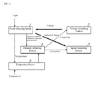
- FIG. 1 is a diagram illustrating a structure of a flame detecting system according to Example according to the present invention.
- the flame detecting system as illustrated in FIG. 1 , is structured from a flame detecting sensor 1, a voltage generating portion 2, a signal generating portion 3, and a parameter relaying portion 4.
- the flame detecting sensor 1 is that which detects light.
- the detection result (a detection signal) by the flame detecting sensor 1 is outputted to a signal generating portion 3.
- the flame detecting sensor 1 has been given a sensitivity parameter, that indicates its own sensitivity, in advance (through, for example, a measurement of the sensitivity parameter at the time at which the flame detecting sensor 1 was manufactured in the factory).
- This flame detecting sensor 1 may be, for example, an ultraviolet photoelectron tube (a UV tube). In this UV tube, when ultraviolet radiation strikes a photosensitive surface of an electrode of the photoelectron tube, a photoelectron is produced through the photoelectric effect, causing a discharge current to flow through the flow of the electrons, to thereby detect the flame.
- the voltage generating portion 2 is that which generates a driving voltage for the flame detecting sensor 1.
- the signal generating portion 3 is that which generates a flame signal indicating the magnitude of the light detected by the flame detecting sensor 1, based on the detection result (detection signal) by the flame detecting sensor 1. Moreover, this signal generating portion 3 may have a function for evaluating, from the flame signal, whether or not there is a flame. The flame signal and/or a signal indicating the evaluation result as to whether or not there is a flame, generated by the signal generating portion 3, is outputted to the outside.
- the parameter relaying portion 4 is that which acquires the sensitivity parameter of the flame detecting sensor 1, and, based on this sensitivity parameter, corrects the operation of the voltage generating portion 2 and/or the signal generating portion 3 so that the flame signal will be identical if there is an identical flame. Note that in FIG. 1 , a case is shown wherein the operations of the voltage generating portion 2 and the signal generating portion 3 are corrected.
- Step ST21 Parameter Acquiring Step
- the parameter relaying portion 4 corrects the operation of the voltage generating portion 2 and/or the signal generating portion 3 so that the flame signal will be identical if there is an identical flame, based on the sensitivity parameter that has been acquired (Step ST22: Correcting Step). This enables outputting of an identical detection result for an identical flame, through enabling sensitivity correction, even when the flame detecting sensor 1, which has unit-to-unit variability in sensitivity, has been replaced.
- a flame detecting system which uses a UV tube, wrapped in paper printed with the sensitivity parameter, as the flame detecting sensor 1, where a ten key, through which the sensitivity parameter can be inputted, is used as the parameter relaying portion 4, and a relay that is able to correct a threshold value based on the sensitivity parameter is used as the signal generating portion 3.
- the flame detecting sensor 1 when the flame detecting sensor 1 is replaced, first an operator references the paper upon which the sensitivity parameter is printed, the paper being wrapped around the UV tube that is the replacement. Following this, the sensitivity parameter is inputted through the ten key.
- the method for relaying the sensitivity parameter to the parameter relaying portion 4 is not limited to that of the method set forth above, but may be a method such as, for example, using a non-contact IC, using a barcode, using a two-dimensional barcode, or inputting a sensitivity parameter, printed on paper using a variable resistance that can be operated from the outside.
- the method may be one that corrects the voltage downward when the sensitivity of the flame detecting sensor 1 is high, or correcting the voltage upward if it is low, or a method for shortening the time over which the voltage is applied if the sensitivity of the flame detecting sensor 1 is high, or lengthening the time over which the voltage is applied if it is low.
- the structure is such that the sensitivity parameter of the flame detecting sensor 1 is acquired and the operation of the voltage generating portion 2 and/or the signal generating portion 3 is corrected so that the detection result will be identical if there is an identical flame, thus enabling an identical detection result to be outputted for an identical flame even if the flame detecting sensor 1 has been replaced.
- FIG. 3 is a diagram illustrating a structure of a flame detecting system according to the Another Example according to the present invention.
- the flame detecting system according to the Another Example, illustrated in FIG. 3 has a temperature sensor 5 that is added to the flame detecting system according to the Example, illustrated in FIG. 1 .
- the other structures are the same, so identical codes are assigned and explanations thereof are omitted.
- the temperature sensor 5 measures the temperature in the environment in which the flame detecting sensor 1 is installed. The measurement result by the temperature sensor 5 is outputted to the parameter relaying portion 4.
- the parameter relaying portion 4 corrects the operation of the voltage generating portion 2 and/or the signal generating portion 3 so that the flame signal will be identical if there is an identical flame, based on the sensitivity parameter that has been acquired and on the temperature that has been measured by the temperature sensor 5.
- FIG. 3 shows a case wherein the temperature sensor 5 is installed separately from the flame detecting sensor 1, it may instead be incorporated within the flame detecting sensor 1.
- Step ST41 Parameter Acquiring Step
- the temperature sensor 5 measures the temperature in the environment in which the flame detecting sensor 1 is installed (Step ST42: Temperature measuring step).
- the temperature that is measured by the temperature sensor 5 may be that which indicates the temperature of the flame detecting sensor 1 main unit.
- it may be the ambient temperature around the flame detecting sensor 1, or it may be temperature information that enables the derivation of information on the temperature that effects the operation of the flame detecting sensor 1.
- a signal indicating the measurement result by the temperature sensor 5 is outputted to the parameter relaying portion 4.
- the parameter relaying portion 4 corrects the operation of the voltage generating portion 2 and/or the signal generating portion 3 so that the flame signal will be identical if there is an identical flame, based on the sensitivity parameter that has been acquired and on the temperature that has been measured by the temperature sensor 5 (Step ST43: Correcting step). This enables outputting of an identical detection result for an identical flame, through enabling sensitivity correction, even when the flame detecting sensor 1, which has unit-to-unit variability in sensitivity, has been replaced.
- this enables outputting of an identical detection result for an identical flame on a plurality of work areas having different temperature environments, by taking into account the temperature characteristics of the flame detecting sensor 1 in the sensor sensitivity correction when a flame detecting sensor 1 has been replaced.
Landscapes
- Physics & Mathematics (AREA)
- General Physics & Mathematics (AREA)
- Spectroscopy & Molecular Physics (AREA)
- Photometry And Measurement Of Optical Pulse Characteristics (AREA)
- Control Of Combustion (AREA)
Abstract
Description
- The present invention relates to a flame detecting system for correcting sensitivity when a flame detecting sensor has been replaced.
- Conventionally in combusting devices such as boilers, flame detection systems have been used for purposes of such as detecting whether or not a flame has been produced properly within the furnace. Moreover, there are cases wherein the flame detecting sensor is used as a sensor in a flame detecting system. The flame detecting system, based on a detection signal that is outputted by the flame detecting sensor detecting light that is produced primarily from the flame, outputs a flame signal indicating the magnitude of the light, or an evaluation results indicating whether or not there is a flame. See, for example, Japanese Unexamined Patent Application Publication
2011-214893 - This flame detecting system is a product with a limited service life, and thus requires replacement upon occasion. On the other hand, there is variability in sensitivity between individual flame detecting sensors. Because of this, there is a problem in that when a flame detecting sensor is replaced in the field, the output may vary even given an identical flame.
- This invention was created in order to solve the issue as described above, and an aspect thereof is to provide a flame detecting system able to output an identical detection result for an identical flame even if the flame detecting sensor has been replaced.
- A flame detecting system according to the present invention includes: a flame detecting sensor that detects light and has a sensitivity parameter that is measured in advance; a voltage generating portion that generates a driving voltage for the flame detecting sensor; a signal generating portion that generates a flame signal expressing a magnitude of the light detected by the flame detecting sensor; and a parameter relaying portion that acquires a sensitivity parameter of the flame detecting sensor and corrects an operation of the voltage generating portion and/or the signal generating portion so that the flame signal becomes identical when there is an identical flame, based on the sensitivity parameter.
- The present invention, structured as described above, enables outputting of identical detection results for identical flames even if the flame detecting sensor has been replaced.
-
-
FIG. 1 is a diagram illustrating a structure of a flame detecting system according to Example according to the present invention. -
FIG. 2 is a flowchart illustrating a sensor sensitivity correcting method for a case wherein a flame detecting sensor has been replaced in a flame detecting system according to the Example according to the present invention. -
FIG. 3 is a diagram illustrating a structure of a flame detecting system according to Another Example according to the present invention. -
FIG. 4 is a flowchart illustrating a sensor sensitivity correcting method for a case wherein a flame detecting sensor has been replaced in a flame detecting system according to the Another Example according to the present invention. - Examples according to the present disclosure will be explained in detail below referencing the figures.
-
FIG. 1 is a diagram illustrating a structure of a flame detecting system according to Example according to the present invention. - The flame detecting system, as illustrated in
FIG. 1 , is structured from aflame detecting sensor 1, avoltage generating portion 2, asignal generating portion 3, and aparameter relaying portion 4. - The
flame detecting sensor 1 is that which detects light. The detection result (a detection signal) by theflame detecting sensor 1 is outputted to asignal generating portion 3. Moreover, theflame detecting sensor 1 has been given a sensitivity parameter, that indicates its own sensitivity, in advance (through, for example, a measurement of the sensitivity parameter at the time at which theflame detecting sensor 1 was manufactured in the factory). Thisflame detecting sensor 1 may be, for example, an ultraviolet photoelectron tube (a UV tube). In this UV tube, when ultraviolet radiation strikes a photosensitive surface of an electrode of the photoelectron tube, a photoelectron is produced through the photoelectric effect, causing a discharge current to flow through the flow of the electrons, to thereby detect the flame. - The
voltage generating portion 2 is that which generates a driving voltage for theflame detecting sensor 1. - The
signal generating portion 3 is that which generates a flame signal indicating the magnitude of the light detected by theflame detecting sensor 1, based on the detection result (detection signal) by theflame detecting sensor 1. Moreover, thissignal generating portion 3 may have a function for evaluating, from the flame signal, whether or not there is a flame. The flame signal and/or a signal indicating the evaluation result as to whether or not there is a flame, generated by thesignal generating portion 3, is outputted to the outside. - The
parameter relaying portion 4 is that which acquires the sensitivity parameter of theflame detecting sensor 1, and, based on this sensitivity parameter, corrects the operation of thevoltage generating portion 2 and/or thesignal generating portion 3 so that the flame signal will be identical if there is an identical flame. Note that inFIG. 1 , a case is shown wherein the operations of thevoltage generating portion 2 and thesignal generating portion 3 are corrected. - The method for correcting the sensor sensitivity when the
flame detecting sensor 1 is replaced in the flame detecting system structured as described above will be explained next in reference toFIG. 2 . - When the
flame detecting sensor 1 is replaced, first theparameter relaying portion 4 acquires the sensitivity parameter of the flame detecting sensor 1 (Step ST21: Parameter Acquiring Step). - Following this, the
parameter relaying portion 4 corrects the operation of thevoltage generating portion 2 and/or thesignal generating portion 3 so that the flame signal will be identical if there is an identical flame, based on the sensitivity parameter that has been acquired (Step ST22: Correcting Step). This enables outputting of an identical detection result for an identical flame, through enabling sensitivity correction, even when theflame detecting sensor 1, which has unit-to-unit variability in sensitivity, has been replaced. - Specific examples of flame detecting systems according to the present invention will be presented next.
- As a specific example of the present invention, there is a flame detecting system which uses a UV tube, wrapped in paper printed with the sensitivity parameter, as the
flame detecting sensor 1, where a ten key, through which the sensitivity parameter can be inputted, is used as theparameter relaying portion 4, and a relay that is able to correct a threshold value based on the sensitivity parameter is used as thesignal generating portion 3. - Given this, when the
flame detecting sensor 1 is replaced, first an operator references the paper upon which the sensitivity parameter is printed, the paper being wrapped around the UV tube that is the replacement. Following this, the sensitivity parameter is inputted through the ten key. - Note that the method for relaying the sensitivity parameter to the
parameter relaying portion 4 is not limited to that of the method set forth above, but may be a method such as, for example, using a non-contact IC, using a barcode, using a two-dimensional barcode, or inputting a sensitivity parameter, printed on paper using a variable resistance that can be operated from the outside. - Moreover, when correcting the driving voltage of the
flame detecting sensor 1 in thevoltage generating portion 2, the method may be one that corrects the voltage downward when the sensitivity of theflame detecting sensor 1 is high, or correcting the voltage upward if it is low, or a method for shortening the time over which the voltage is applied if the sensitivity of theflame detecting sensor 1 is high, or lengthening the time over which the voltage is applied if it is low. - As described above, given this Example, the structure is such that the sensitivity parameter of the
flame detecting sensor 1 is acquired and the operation of thevoltage generating portion 2 and/or thesignal generating portion 3 is corrected so that the detection result will be identical if there is an identical flame, thus enabling an identical detection result to be outputted for an identical flame even if theflame detecting sensor 1 has been replaced. - In Another Example a case is presented wherein temperature characteristics are included in the sensitivity parameters for the
flame detecting sensor 1, to take into account temperature characteristics as well in correcting the operations. -
FIG. 3 is a diagram illustrating a structure of a flame detecting system according to the Another Example according to the present invention. The flame detecting system according to the Another Example, illustrated inFIG. 3 , has atemperature sensor 5 that is added to the flame detecting system according to the Example, illustrated inFIG. 1 . The other structures are the same, so identical codes are assigned and explanations thereof are omitted. - The
temperature sensor 5 measures the temperature in the environment in which theflame detecting sensor 1 is installed. The measurement result by thetemperature sensor 5 is outputted to theparameter relaying portion 4. - Given this, the
parameter relaying portion 4 corrects the operation of thevoltage generating portion 2 and/or thesignal generating portion 3 so that the flame signal will be identical if there is an identical flame, based on the sensitivity parameter that has been acquired and on the temperature that has been measured by thetemperature sensor 5. - Note that while
FIG. 3 shows a case wherein thetemperature sensor 5 is installed separately from theflame detecting sensor 1, it may instead be incorporated within theflame detecting sensor 1. - The method for correcting the sensor sensitivity when the
flame detecting sensor 1 is replaced in the flame detecting system structured as described above will be explained next in reference toFIG. 4 . - When the
flame detecting sensor 1 is replaced, first theparameter relaying portion 4 acquires the sensitivity parameter of the flame detecting sensor 1 (Step ST41: Parameter Acquiring Step). - Moreover, the
temperature sensor 5 measures the temperature in the environment in which theflame detecting sensor 1 is installed (Step ST42: Temperature measuring step). Here the temperature that is measured by thetemperature sensor 5 may be that which indicates the temperature of theflame detecting sensor 1 main unit. For example, it may be the ambient temperature around theflame detecting sensor 1, or it may be temperature information that enables the derivation of information on the temperature that effects the operation of theflame detecting sensor 1. A signal indicating the measurement result by thetemperature sensor 5 is outputted to theparameter relaying portion 4. - Following this, the
parameter relaying portion 4 corrects the operation of thevoltage generating portion 2 and/or thesignal generating portion 3 so that the flame signal will be identical if there is an identical flame, based on the sensitivity parameter that has been acquired and on the temperature that has been measured by the temperature sensor 5 (Step ST43: Correcting step). This enables outputting of an identical detection result for an identical flame, through enabling sensitivity correction, even when theflame detecting sensor 1, which has unit-to-unit variability in sensitivity, has been replaced. - In this way, in addition to the effects in the Example, this enables outputting of an identical detection result for an identical flame on a plurality of work areas having different temperature environments, by taking into account the temperature characteristics of the
flame detecting sensor 1 in the sensor sensitivity correction when aflame detecting sensor 1 has been replaced. - Note that the various examples set forth above can be combined freely within the scope of the invention, or any given structural element within any of the examples may be modified or any given structural element may be omitted in any of the examples, within the scope of the present disclosure.
-
- 1: Flame Detecting Sensor
- 2: Voltage Generating Portion
- 3: Signal Generating Portion
- 4: Parameter Relaying Portion
- 5: Temperature Sensor
Claims (3)
- A flame detecting system comprising:a flame detecting sensor (1) adapted to detect light, the flame detecting sensor (1) having a sensitivity parameter that is measured in advance;a voltage generating portion (2) adapted to generate a driving voltage for the flame detecting sensor (1);a signal generating portion (3) adapted to generate a flame signal expressing a magnitude of the light detected by the flame detecting sensor (1); anda parameter relaying portion (4) adapted to acquire a sensitivity parameter of the flame detecting sensor (1) and to correct an operation of the voltage generating portion (2) and/or the signal generating portion (3) so that the flame signal becomes identical when there is an identical flame, based on the sensitivity parameter.
- The flame detecting system as set forth in Claim 1, further comprising:a temperature sensor (5) adapted to measure a temperature in the installation environment for the flame detecting system; whereina temperature characteristic is included in the sensitivity parameter; andthe parameter relaying portion (4) is adapted to correct an operation of the voltage generating portion (2) and/or the signal generating portion (3) so that the flame signal becomes identical when there is an identical flame, based on the sensitivity parameter and the temperature measured by the temperature sensor (5).
- The flame detecting system as set forth in Claim 1 or 2, wherein:the signal generating portion (3) is adapted to evaluate, from the flame signal, whether or not there is a flame.
Applications Claiming Priority (1)
| Application Number | Priority Date | Filing Date | Title |
|---|---|---|---|
| JP2014079534A JP2015200575A (en) | 2014-04-08 | 2014-04-08 | flame detection system |
Publications (1)
| Publication Number | Publication Date |
|---|---|
| EP2930483A1 true EP2930483A1 (en) | 2015-10-14 |
Family
ID=52823499
Family Applications (1)
| Application Number | Title | Priority Date | Filing Date |
|---|---|---|---|
| EP15162546.4A Withdrawn EP2930483A1 (en) | 2014-04-08 | 2015-04-07 | Flame detecting system |
Country Status (4)
| Country | Link |
|---|---|
| US (1) | US20150285674A1 (en) |
| EP (1) | EP2930483A1 (en) |
| JP (1) | JP2015200575A (en) |
| CN (1) | CN104976636A (en) |
Families Citing this family (8)
| Publication number | Priority date | Publication date | Assignee | Title |
|---|---|---|---|---|
| JP6782612B2 (en) * | 2016-11-21 | 2020-11-11 | アズビル株式会社 | Flame detection system |
| JP6782613B2 (en) * | 2016-11-21 | 2020-11-11 | アズビル株式会社 | Flame detection system |
| JP6824794B2 (en) * | 2017-03-17 | 2021-02-03 | アズビル株式会社 | Combustion control device and method |
| JP2018155443A (en) * | 2017-03-17 | 2018-10-04 | アズビル株式会社 | Combustion control device and method |
| JP6889082B2 (en) * | 2017-09-29 | 2021-06-18 | アズビル株式会社 | Flame sensor drive circuit |
| US10648857B2 (en) * | 2018-04-10 | 2020-05-12 | Honeywell International Inc. | Ultraviolet flame sensor with programmable sensitivity offset |
| CN109489937A (en) * | 2018-10-17 | 2019-03-19 | 宝钢湛江钢铁有限公司 | Multi fuel fire examines optical-fiber intelligent detection system and detection method |
| CN116045303B (en) * | 2022-12-13 | 2025-07-25 | 华能巢湖发电有限责任公司 | Device and method for online monitoring of boiler combustion state based on spectrum analysis |
Citations (4)
| Publication number | Priority date | Publication date | Assignee | Title |
|---|---|---|---|---|
| US3940753A (en) * | 1973-09-25 | 1976-02-24 | Cerberus Ag | Detection of presence or absence of flames |
| WO1997032288A1 (en) * | 1996-03-01 | 1997-09-04 | Fire Sentry Corporation | Process and system for flame detection |
| US20050247883A1 (en) * | 2004-05-07 | 2005-11-10 | Burnette Stanley D | Flame detector with UV sensor |
| JP2011214893A (en) | 2010-03-31 | 2011-10-27 | Yamatake Corp | Flame sensor |
Family Cites Families (6)
| Publication number | Priority date | Publication date | Assignee | Title |
|---|---|---|---|---|
| JPS61178621A (en) * | 1985-02-04 | 1986-08-11 | Hochiki Corp | Flame detector |
| CN1287736C (en) * | 2001-06-22 | 2006-12-06 | 株式会社日立医药 | X-ray image diagnosing device and x-ray image data correcting method |
| CA2588254C (en) * | 2006-05-12 | 2014-07-15 | Fossil Power Systems Inc. | Flame detection device and method of detecting flame |
| JP2012210291A (en) * | 2011-03-31 | 2012-11-01 | Ge Medical Systems Global Technology Co Llc | Detector module and radiation imaging apparatus |
| CN203364162U (en) * | 2013-06-21 | 2013-12-25 | 黑龙江省中能控制工程有限公司 | Lightpipe type flame detector probe |
| CN103542424B (en) * | 2013-11-01 | 2015-09-09 | 合肥金星机电科技发展有限公司 | High-temperature probe assembly |
-
2014
- 2014-04-08 JP JP2014079534A patent/JP2015200575A/en active Pending
-
2015
- 2015-04-06 US US14/679,085 patent/US20150285674A1/en not_active Abandoned
- 2015-04-07 EP EP15162546.4A patent/EP2930483A1/en not_active Withdrawn
- 2015-04-08 CN CN201510163989.2A patent/CN104976636A/en active Pending
Patent Citations (4)
| Publication number | Priority date | Publication date | Assignee | Title |
|---|---|---|---|---|
| US3940753A (en) * | 1973-09-25 | 1976-02-24 | Cerberus Ag | Detection of presence or absence of flames |
| WO1997032288A1 (en) * | 1996-03-01 | 1997-09-04 | Fire Sentry Corporation | Process and system for flame detection |
| US20050247883A1 (en) * | 2004-05-07 | 2005-11-10 | Burnette Stanley D | Flame detector with UV sensor |
| JP2011214893A (en) | 2010-03-31 | 2011-10-27 | Yamatake Corp | Flame sensor |
Also Published As
| Publication number | Publication date |
|---|---|
| CN104976636A (en) | 2015-10-14 |
| US20150285674A1 (en) | 2015-10-08 |
| JP2015200575A (en) | 2015-11-12 |
Similar Documents
| Publication | Publication Date | Title |
|---|---|---|
| US20150285674A1 (en) | Flame detecting system | |
| JP6782612B2 (en) | Flame detection system | |
| JP6508772B2 (en) | Flame detection system | |
| KR20180133327A (en) | Flame detecting system | |
| CN108088559A (en) | Flame detector system | |
| GB201209735D0 (en) | Improvements in touch sensitive displays | |
| EP2039997A2 (en) | Ultraviolet frame sensor with run-on detection | |
| WO2007127053A3 (en) | Non-intrusive pressure gage | |
| EP3273221B1 (en) | System and method for detecting corrosion | |
| WO2017105814A1 (en) | Pressure sensor drift detection and correction | |
| JP5832948B2 (en) | Flame detection device | |
| JP2016218001A (en) | Flame detection system | |
| US20160231188A1 (en) | Pressure measurement device with automatic position correction | |
| CA2853430C (en) | Systems and methods for overheat detection system event location | |
| KR20210080141A (en) | Smart sensor and gas detecting device including thereof | |
| US20180181084A1 (en) | Electronic device | |
| TW201614233A (en) | Test sensor system and methods for using the same | |
| US10416104B2 (en) | Gas sensing device | |
| JP2007263845A (en) | Flow rate measuring device and flow rate measuring method | |
| US20180217017A1 (en) | Pressure sensor and method for monitoring a pressure sensor | |
| CN109631972A (en) | Method for monitoring sensor function | |
| MY171309A (en) | An arc smelting system and method of monitoring the length of an electrode in said system | |
| KR101454599B1 (en) | Fault Detection Device and Method for flash lamp of high-energy laser system | |
| US20240395524A1 (en) | Process and device for detecting an operating state of a photoionization detector | |
| KR20190101933A (en) | Method for detecting failure of sensor of atmosphere environment |
Legal Events
| Date | Code | Title | Description |
|---|---|---|---|
| PUAI | Public reference made under article 153(3) epc to a published international application that has entered the european phase |
Free format text: ORIGINAL CODE: 0009012 |
|
| AK | Designated contracting states |
Kind code of ref document: A1 Designated state(s): AL AT BE BG CH CY CZ DE DK EE ES FI FR GB GR HR HU IE IS IT LI LT LU LV MC MK MT NL NO PL PT RO RS SE SI SK SM TR |
|
| AX | Request for extension of the european patent |
Extension state: BA ME |
|
| 17P | Request for examination filed |
Effective date: 20160414 |
|
| RBV | Designated contracting states (corrected) |
Designated state(s): AL AT BE BG CH CY CZ DE DK EE ES FI FR GB GR HR HU IE IS IT LI LT LU LV MC MK MT NL NO PL PT RO RS SE SI SK SM TR |
|
| STAA | Information on the status of an ep patent application or granted ep patent |
Free format text: STATUS: THE APPLICATION HAS BEEN WITHDRAWN |
|
| 18W | Application withdrawn |
Effective date: 20160905 |