EP2930481A1 - Systems, methods, and apparatus for suppression of optical interference fringes in optical spectroscopy - Google Patents
Systems, methods, and apparatus for suppression of optical interference fringes in optical spectroscopy Download PDFInfo
- Publication number
- EP2930481A1 EP2930481A1 EP15161836.0A EP15161836A EP2930481A1 EP 2930481 A1 EP2930481 A1 EP 2930481A1 EP 15161836 A EP15161836 A EP 15161836A EP 2930481 A1 EP2930481 A1 EP 2930481A1
- Authority
- EP
- European Patent Office
- Prior art keywords
- media
- optical
- time
- modifying
- pressure
- Prior art date
- Legal status (The legal status is an assumption and is not a legal conclusion. Google has not performed a legal analysis and makes no representation as to the accuracy of the status listed.)
- Granted
Links
Images


Classifications
-
- G—PHYSICS
- G01—MEASURING; TESTING
- G01J—MEASUREMENT OF INTENSITY, VELOCITY, SPECTRAL CONTENT, POLARISATION, PHASE OR PULSE CHARACTERISTICS OF INFRARED, VISIBLE OR ULTRAVIOLET LIGHT; COLORIMETRY; RADIATION PYROMETRY
- G01J3/00—Spectrometry; Spectrophotometry; Monochromators; Measuring colours
- G01J3/02—Details
- G01J3/0297—Constructional arrangements for removing other types of optical noise or for performing calibration
-
- G—PHYSICS
- G01—MEASURING; TESTING
- G01J—MEASUREMENT OF INTENSITY, VELOCITY, SPECTRAL CONTENT, POLARISATION, PHASE OR PULSE CHARACTERISTICS OF INFRARED, VISIBLE OR ULTRAVIOLET LIGHT; COLORIMETRY; RADIATION PYROMETRY
- G01J3/00—Spectrometry; Spectrophotometry; Monochromators; Measuring colours
- G01J3/28—Investigating the spectrum
- G01J3/42—Absorption spectrometry; Double beam spectrometry; Flicker spectrometry; Reflection spectrometry
-
- G—PHYSICS
- G01—MEASURING; TESTING
- G01J—MEASUREMENT OF INTENSITY, VELOCITY, SPECTRAL CONTENT, POLARISATION, PHASE OR PULSE CHARACTERISTICS OF INFRARED, VISIBLE OR ULTRAVIOLET LIGHT; COLORIMETRY; RADIATION PYROMETRY
- G01J3/00—Spectrometry; Spectrophotometry; Monochromators; Measuring colours
- G01J3/28—Investigating the spectrum
- G01J3/42—Absorption spectrometry; Double beam spectrometry; Flicker spectrometry; Reflection spectrometry
- G01J3/433—Modulation spectrometry; Derivative spectrometry
-
- G—PHYSICS
- G02—OPTICS
- G02F—OPTICAL DEVICES OR ARRANGEMENTS FOR THE CONTROL OF LIGHT BY MODIFICATION OF THE OPTICAL PROPERTIES OF THE MEDIA OF THE ELEMENTS INVOLVED THEREIN; NON-LINEAR OPTICS; FREQUENCY-CHANGING OF LIGHT; OPTICAL LOGIC ELEMENTS; OPTICAL ANALOGUE/DIGITAL CONVERTERS
- G02F1/00—Devices or arrangements for the control of the intensity, colour, phase, polarisation or direction of light arriving from an independent light source, e.g. switching, gating or modulating; Non-linear optics
- G02F1/01—Devices or arrangements for the control of the intensity, colour, phase, polarisation or direction of light arriving from an independent light source, e.g. switching, gating or modulating; Non-linear optics for the control of the intensity, phase, polarisation or colour
- G02F1/0128—Devices or arrangements for the control of the intensity, colour, phase, polarisation or direction of light arriving from an independent light source, e.g. switching, gating or modulating; Non-linear optics for the control of the intensity, phase, polarisation or colour based on electro-mechanical, magneto-mechanical, elasto-optic effects
- G02F1/0131—Devices or arrangements for the control of the intensity, colour, phase, polarisation or direction of light arriving from an independent light source, e.g. switching, gating or modulating; Non-linear optics for the control of the intensity, phase, polarisation or colour based on electro-mechanical, magneto-mechanical, elasto-optic effects based on photo-elastic effects, e.g. mechanically induced birefringence
-
- G—PHYSICS
- G02—OPTICS
- G02F—OPTICAL DEVICES OR ARRANGEMENTS FOR THE CONTROL OF LIGHT BY MODIFICATION OF THE OPTICAL PROPERTIES OF THE MEDIA OF THE ELEMENTS INVOLVED THEREIN; NON-LINEAR OPTICS; FREQUENCY-CHANGING OF LIGHT; OPTICAL LOGIC ELEMENTS; OPTICAL ANALOGUE/DIGITAL CONVERTERS
- G02F1/00—Devices or arrangements for the control of the intensity, colour, phase, polarisation or direction of light arriving from an independent light source, e.g. switching, gating or modulating; Non-linear optics
- G02F1/01—Devices or arrangements for the control of the intensity, colour, phase, polarisation or direction of light arriving from an independent light source, e.g. switching, gating or modulating; Non-linear optics for the control of the intensity, phase, polarisation or colour
- G02F1/0147—Devices or arrangements for the control of the intensity, colour, phase, polarisation or direction of light arriving from an independent light source, e.g. switching, gating or modulating; Non-linear optics for the control of the intensity, phase, polarisation or colour based on thermo-optic effects
-
- G—PHYSICS
- G02—OPTICS
- G02F—OPTICAL DEVICES OR ARRANGEMENTS FOR THE CONTROL OF LIGHT BY MODIFICATION OF THE OPTICAL PROPERTIES OF THE MEDIA OF THE ELEMENTS INVOLVED THEREIN; NON-LINEAR OPTICS; FREQUENCY-CHANGING OF LIGHT; OPTICAL LOGIC ELEMENTS; OPTICAL ANALOGUE/DIGITAL CONVERTERS
- G02F1/00—Devices or arrangements for the control of the intensity, colour, phase, polarisation or direction of light arriving from an independent light source, e.g. switching, gating or modulating; Non-linear optics
- G02F1/01—Devices or arrangements for the control of the intensity, colour, phase, polarisation or direction of light arriving from an independent light source, e.g. switching, gating or modulating; Non-linear optics for the control of the intensity, phase, polarisation or colour
- G02F1/19—Devices or arrangements for the control of the intensity, colour, phase, polarisation or direction of light arriving from an independent light source, e.g. switching, gating or modulating; Non-linear optics for the control of the intensity, phase, polarisation or colour based on variable-reflection or variable-refraction elements not provided for in groups G02F1/015 - G02F1/169
-
- G—PHYSICS
- G02—OPTICS
- G02F—OPTICAL DEVICES OR ARRANGEMENTS FOR THE CONTROL OF LIGHT BY MODIFICATION OF THE OPTICAL PROPERTIES OF THE MEDIA OF THE ELEMENTS INVOLVED THEREIN; NON-LINEAR OPTICS; FREQUENCY-CHANGING OF LIGHT; OPTICAL LOGIC ELEMENTS; OPTICAL ANALOGUE/DIGITAL CONVERTERS
- G02F1/00—Devices or arrangements for the control of the intensity, colour, phase, polarisation or direction of light arriving from an independent light source, e.g. switching, gating or modulating; Non-linear optics
- G02F1/01—Devices or arrangements for the control of the intensity, colour, phase, polarisation or direction of light arriving from an independent light source, e.g. switching, gating or modulating; Non-linear optics for the control of the intensity, phase, polarisation or colour
- G02F1/21—Devices or arrangements for the control of the intensity, colour, phase, polarisation or direction of light arriving from an independent light source, e.g. switching, gating or modulating; Non-linear optics for the control of the intensity, phase, polarisation or colour by interference
Definitions
- aspects of the disclosure relate generally to optical spectroscopy and more specifically to noise management in optical spectroscopy.
- Certain branches of analytical spectroscopy can rely on optical spectroscopy to observe and study the chemistry of fluids (e.g., presence of CO 2 , H 2 O, or other compounds) and/or the dynamics of chemical reactions (such as oxidation and/or combustion).
- optical noise arising from optical interference between different pathways for light propagation within the equipment utilized for the optical spectroscopy is often the primary sensitivity-limiting factor in such spectroscopy.
- Conventional solutions to suppress the optical noise are typically prohibitively expensive, cumbersome to implement, and/or limited to current generation equipment, without a backwards compatible implementation.
- aspects of the disclosure include suppression of optical interference fringes in optical spectra via a modification to the refractive index of media that forms or is contained in one or more components of equipment utilized for optical spectroscopy.
- a modification can yield changes in the optical path of light propagating through at least one of the media, with the ensuing changes in the spectral structure of interference between light propagating through different optical paths.
- the refractive index of the media that forms or is contained in one or more components can be modified via application of a time-dependent stimulus to at least one of the one or more components.
- the applied stimulus can include pressure, mechanical strain or stress, temperature, a combination thereof, or the like.
- the disclosure recognizes and addresses, in at least certain aspects, the issue of optical noise in analytical spectroscopy.
- the disclosure provides devices, systems, and/or techniques for management (e.g., reduction and/or control) of optical noise in optical spectroscopy.
- the disclosure permits suppression of optical interference fringes in optical spectra via a modification to the refractive index of media that forms or is contained in one or more components of equipment utilized for optical spectroscopy. Such a modification can yield changes in the optical path of light propagating through at least one of the media, with the ensuing changes in the spectroscopy structure of interference between light propagating through different optical paths.
- the media can include transparent or semi-transparent materials (either solids, fluids (such as, liquid, gas, or a combination thereof), or combinations thereof).
- the refractive index of the media that forms or is contained in one or more components can be modified via application of a time-dependent stimulus (periodic or otherwise) to at least one of the one or more components.
- the applied stimulus can include pressure, mechanical strain or stress, temperature, a combination thereof, or the like.
- application of the stimulus can be implemented via passive control components, such as pneumatic components without active control.
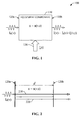
- FIG. 1 presents an example of an equipment component 110 in accordance with at least certain aspects of the disclosure.
- the equipment component 110 can be embodied in or can include an enclosure of an optical spectroscopy analyzer.
- Such an enclosure can include one or more compartments, where at least one of the one or more compartments can be substantially hermetic or otherwise sealed.
- the equipment component 110 can be embodied in or can include an optical element (e.g., a lens, a window, or the like) of the optical spectroscopy analyzer.
- the equipment component 110 can be embodied in or can include a combination of an enclosure and a group of optical members of the optical spectroscopy analyzer.
- the equipment component 110 can contain a solid, a fluid (such as a liquid or gas) or a mixture thereof, and can include a first surface 120a and a second surface 120b and a space (e.g., separation) between the first surface 120a and the second surface 120b.
- the equipment component 110 can be a compartment of the optical spectroscopy equipment, such as a tunable diode laser spectroscopy (TDLS) analyzer, and can contain the gas, the fluid (such as a gas or liquid) or the mixture thereof that can be probed via such equipment.
- TDLS tunable diode laser spectroscopy
- the equipment component 110 can be an optical element (which also may be referred to as an optical member) of the optical spectroscopy equipment.
- the optical element can be a lens (e.g., a meniscus, an aspheric lens, or the like), or a transparent or semi-transparent window.
- a lens or window can be solid or can include a mixture of a solid and a fluid.
- the equipment component 110 can include a combination of one or more compartments and/or one or more optical members.
- the equipment component 110 can include a compartment having a light source of the optical spectroscopy equipment (e.g., a gas-discharge lamp or a laser), a collimating lens, and a propagation window (as best shown in FIG. 5 discussed herein), where the compartment contains a fluid (such as a gas, liquid, or some combination thereof).
- a light source of the optical spectroscopy equipment e.g., a gas-discharge lamp or a laser
- collimating lens e.g., a collimating lens
- a propagation window as best shown in FIG. 5 discussed herein
- the equipment component 110 can be configured ( e.g., assembled or mounted) to receive light having a frequency (v) and intensity ( I 0 ) , and can permit propagation of the received light.
- the received light can be utilized or otherwise leveraged to probe a material (e.g., a solid, a gas, a liquid, or a mixture thereof) via the optical spectroscopy equipment that includes the equipment component 110.
- a material e.g., a solid, a gas, a liquid, or a mixture thereof
- such a material can be contained within the equipment component 110.
- the intensity I 0 can depend on the frequency ⁇ (or wavelength), in certain embodiments, such a dependency can be weak, yielding an approximately constant intensity over a range of frequencies.
- the light that is received can be substantially monochromatic (visible or otherwise) or can be composed of multiple frequencies within the visible or non-visible range of the electromagnetic spectrum. As illustrated, the light can be received at the surface 120a and can propagate trough the equipment component 110, exiting through the surface 120b. It can be readily apparent that the surfaces 120a and 120b can be embodied in or can include a transparent or semi-transparent material.
- the light that propagates through the equipment component 110 can have an intensity I ( v ) that can depend on frequency. Without intending to be bound or otherwise limited by theory and/or modeling, in one aspect, such dependency can be attributed to a signal I s ( v ) substantially originated in the optical absorption spectrum of a material contained in or that forms the equipment component 110, and optical noise ⁇ ( v ) substantially originated from optical interference between light that propagates from the first surface 120a to the second surface 120b through different optical paths.
- the optical interference may be referred to as "etalon effect” and generally yields fringes of optical interference associated with alternating maxima and minima of intensity, or strength, of the optical noise ⁇ ( v ).
- the optical interference fringes may be referred to as "etalons," and such maxima and minima can arise from constructive interference and destructive interference between light that propagates through different optical paths between surfaces 120a and 120b.
- FIG. 2 illustrates two optical paths between surfaces 120a and 120b: a first optical path 210 in which light propagates directly from the first surface 120a to the second surface 120b; and a second optical path 220 in which light propagates from the first surface 120a to the second surface 120b, reflects off the second surface 120b and propagates to the first surface 120a, and reflects off the first surface 120a and propagates back to the second surface 120b.
- the first optical path 210 and second optical path 120 are represented with lines of different thickness, and have optical distances d ⁇ n and 2d ⁇ n, respectively, where d represents the distance between the first surface 120a and the second surface 120b, and n represents the refractive index of the medium (e.g., a solid, a fluid, or a combination thereof) contained within such surfaces.
- the optical noise ⁇ ( v ) typically distorts the observed intensity I ( v ), and thus, the optical noise can mar the analysis.
- Such analysis can include chemical analysis based at least in part on the spectroscopic features of I ( v ).
- the equipment component 110 can be submitted to a time-dependent stimulus ⁇ ( t ) that can modify the refractive index of the material contained in or that forms the equipment component 110.
- the stimulus can include pressure, mechanical strain or stress, temperature, a combination thereof, or the like.
- time-dependent modification of the refractive index of a material can occur in time scale greater than the time scale associated with modification of the refractive index via application of pressure.
- a refractive index in response to application of the stimulus ⁇ ( t ) (which is pictorially represented with an arrow), can depend on light frequency (or wavelength) and time, which can cause an optical path of light propagating within the equipment component 110 to be time-dependent as well.
- n n(v, t) (where as described herein, n represents the refractive index of a medium contained in or that forms the equipment component 110, v represents the frequency of light that propagates within the equipment component 110, and t represents time) and the optical path can be expressed as ⁇ n ( v,t ) , where is a geometric distance between two surfaces within the equipment component 110 (e.g., can be the distance between the first surface 120a and the second surface 120b).
- a suitable integration period can permit averaging multiple scans (or measurements) of I ( v ) and thus suppressing the contribution of the time-dependent optical noise ⁇ ( v , t) over time. Such suppression represents, in one aspect, a form of management of the optical noise.
- such a suppression of the time-dependent optical noise can originate from different strengths of the optical noise at a frequency v over time-e.g., the optical noise at the frequency v can transition between high strength (e.g., constructive interference maximum) and low strength ( e.g., destructive interference minimum) over time.
- the stimulus ⁇ ( t ) 130 (where ⁇ represents stimulus and t represents time) can vary periodically from ⁇ low to ⁇ high according to a specific waveform. Although a sawtooth waveform is shown in FIG. 3 , other waveforms ( e.g., triangular, sinusoidal, square, ...) can be contemplated.
- the stimulus ⁇ ( t ) can vary aperiodically from ⁇ low to ⁇ high .
- one or more perturbation units 410 can provide, at least in part, the stimulus ⁇ ( t ) 130.
- at least one of the perturbation unit(s) 410 can be communicatively, fixedly, removably, mechanically, electrically, electromechanically, and/or thermally coupled to the equipment component 110 via one or more coupling members 420.
- a coupling member can be embodied in or can include a pipe, a flange, an inlet, a thermally conductive element, an electrically conductive element, a combination thereof, or the like.
- the perturbation unit(s) 410 can include at least one unit that can provide the stimulus- e.g. , a pneumatic valve, a piston, a bellow, a heating element, a thermoelectric component, and/or a component to apply a mechanical strain/stress-and at least one unit that can control the application of the stimulus.
- a unit can be embodied in or can include an electronic controller having a processor that can execute instructions (e.g., computer-accessible instructions) retained in a memory device in order to cause the application of at least part of the stimulus via the at least one unit that can provide the stimulus.
- the at least one unit that can control the application of the stimulus can include a mechanism (e.g., an electronic or mechanic timer) that can regulate electronically and/or mechanically the operation of the at least one unit that can provide the stimulus (e.g., implementation of an open-shut cycle of a valve).
- the at least one unit that can control the at least one unit that can provide the stimulus can include an external pneumatic controller or an electronic controller (which can be embodied in or can include a processing unit or a processor). Accordingly, in one aspect, such embodiments may be referred to as active control embodiments.
- the perturbation unit(s) 410 can include at least one unit that can provide the stimulus, and can passively control the application thereof.
- mechanism(s) and/or controller(s) can be integrated into or otherwise combined or included with the at least one unit that can provide the stimulus (e.g., a passive pneumatic system).
- passive control embodiments can provide simplicity, reliability, and/or can permit cost management of the application of the stimulus in accordance with aspects of the disclosure.
- the stimulus ⁇ ( t ) can be applied by heating or cooling a material that embodies or that is contained in the equipment component 110, or by applying a mechanical stress or strain to such material.
- a material that embodies or that is contained in the equipment component 110
- a mechanical stress or strain to such material.
- optical noise originating from interference between light propagation between two surfaces of the optical member can be mitigated by (a) heating or cooling the optical member, and/or (b) applying a mechanical stress or strain to the optical member in order to modify the optical member's refractive index.
- At least one of the perturbation unit(s) 410 and at least one of the coupling members 420 can permit modifying the pressure applied to the equipment component 110 as a function of time.
- ⁇ ( t ) P(t)
- P ( t ) is a function of time indicative or otherwise representative of the pressure applied to the equipment component 110.
- the equipment component 110 can contain a gas, such as a noble gas or a substantially inert gas.
- the equipment component 110 can be embodied in a compartment of an optical spectroscopy analyzer.
- transitions between constructive interference and destructive interference can permit management of optical noise in optical spectroscopy.
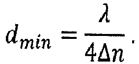
- a refractive index shift ⁇ n caused by a change in gas pressure of about 26.6 kPa (e.g., about 200 Torr), can yield a d min of about 2.4 mm.
- ⁇ n ⁇ P n TP - 1 P
- ranges for the magnitude of the stimulus can be determined a priori, which can permit design of suitable stimuli in order to manage optical noise in optical spectroscopy.
- pressure can be applied to the fluid (e.g., a gas, liquid or combination thereof) that can be contained in such compartment or enclosure.
- fluid e.g., a gas, liquid or combination thereof
- the at least one of the perturbation unit(s) 410 can permit (A) injection of fluid into the compartment or enclosure in order to increase the pressure of the fluid therein from a first pressure (e.g., P low ) to a second pressure (e.g., P high ) over a predetermined time interval, and (B) release of fluid from the compartment or enclosure in order to decrease the pressure from the second pressure (e.g., P high ) to the first pressure (e.g., P low ) over another predetermined interval.
- the injection-release cycle can be repeated in order to produce a periodic modification of the pressure within the equipment component 110.
- FIG. 5 presents a block diagram of an example embodiment 500 of the equipment component 110, the coupling member(s) 420, and the perturbation unit(s) 410 in accordance with at least certain aspects of the disclosure.
- the functional elements in the illustrated block diagram are shown in a cross-section representation.
- the equipment component 510 is embodied in an enclosure having a compartment 520 of the optical spectroscopy equipment, and an inlet conduit 560 providing a fluidic pathway between the compartment 520 and the exterior of the equipment component 510.
- the compartment 520 can include additional equipment components, such as a light source 530, an optical member 540 (e.g., a collimating lens), and a second optical member 550 (e.g., a window formed of a transparent or semi-transparent material, such as fused silica or other glass).
- the light source 530 can be embodied in or can include gas-discharge lamp or a tunable laser (such as a diode laser, a CO 2 laser, a dye laser, or a transition-metal solid-state laser) that can provide light (visible or otherwise) having wavelengths in a predetermined portion of the electromagnetic spectrum.
- the inlet conduit 560 permits injection of gas (e.g., instrument gas, nitrogen, or a noble gas) into the compartment 520.
- gas e.g., instrument gas, nitrogen, or a noble gas
- a gas source (not depicted in FIG. 5 ) can supply a substantially constant flow of the gas, which may be referred to as purge gas.
- the coupling member(s) 420 can be embodied in an outlet conduit 570 providing a fluidic pathway out of the compartment 520, which is coupled directly and/or fluidically to a valve 580 embodying the perturbation unit(s) 410.
- the valve 580 may be referred to as "modulating valve,” and, in one aspect, can be embodied in a pneumatic valve configured to receive pressurized or otherwise compressed gas from the compartment 520 via the outlet conduit 570.
- the valve 580 can be configured to open at about a first pressure (e.g., P high ) and shut at about a second pressure (e.g., P low ) that is lower than the first pressure, thereby producing a substantially periodic variation of the pressure of the gas contained in the compartment 520. (See, e.g., FIG. 3 ). It should be appreciated that, in certain embodiments, the modulating valve 580 can be configured to produce substantially any periodic variation of pressure (e.g., a square waveform, a triangular waveform, a sinusoidal waveform, or the like) or time-dependent pressure profile (periodic or aperiodic).
- a mechanism e.g., an electronic or mechanical timer
- the valve 580 e.g., implementation of an open-shut cycle
- an external pneumatic or electronic controller (which can be embodied in or can include a computer or processing unit) can regulate the operation of the modulating valve 580.
- the time-dependent variation of pressure of the gas contained in the compartment 520 can yield a time-dependent variation of the refractive index of such gas, with the ensuing mitigation of optical noise on the intensity of light emanating from the optical member 550.
- the optical noise can include optical interference fringes of constructive interference between light that propagates between a pair of surfaces through difference optical paths.
- Such fringes also may be referred to as "etalons,” and can include etalons originating from light propagation between the light source 530 and the optical element 540 (referred to as “lens-light-source” etalons); the optical element 540 and the optical element 550 (referred to as “window-lens” etalons); and the light source 530 and the optical element 550 (referred to as “window-light-source” etalons).
- substantially all free-space etalons in the compartment 410 can be averaged out or otherwise removed over time during measurement of the intensity of light propagating through the optical member 550.
- the disclosure can permit mitigation of optical noise due to optical interference via time-dependent modification of the refractive index of substantially any component of an optical spectroscopy analyzer, including the light-source compartment, a detector compartment, a sample cell or chamber, or a combination thereof.
- a group of equipment components can be subject to respective stimuli at least in order to effect a time-dependent variation of the respective refractive index of such components. As an illustration, FIG.
- FIG. 6 presents three equipment components 610a-610c that can be submitted to respective stimuli 620a-620c in order to modify the respective refractive indices as a function of time, thereby producing refractive indices n a ( v, t), n b ( v, t), and n c ( v , t ), with the ensuing mitigation of optical noise in accordance with aspects described herein.
- examples of a technique for management of optical noise in optical spectroscopy in accordance with at least certain aspects of the disclosure can be better appreciated with reference to the diagram in FIG. 7 .
- the examples of the techniques disclosed herein are presented and described as a series of blocks, with each block representing an action or an operation in a method, for example.
- the disclosed techniques e.g., process(es), procedure(s), method(s), and the like
- process(es), procedure(s), method(s), and the like are not limited by the order of blocks and associated actions or operations, as some blocks may occur in different orders and/or concurrently with other blocks from that are shown and described herein.
- the various techniques of the disclosure can be alternatively represented as a series of interrelated states or events, such as in a state diagram.
- not all illustrated blocks, and associated action(s) or operation(s) may be required to implement a technique in accordance with one or more aspects of the disclosure.
- two or more of the disclosed techniques can be implemented in combination with each other, to accomplish one or more features and/or advantages described herein.
- At least a portion of the techniques of the disclosure can be retained on an article of manufacture, or computer-readable storage medium in order to permit or facilitate transporting and transferring such techniques to a computing device (such as a microcontroller, a programmable logic controller, a programmable logic relay, and the like) for execution, and thus implementation, by a processor of the computing device or for storage in a memory thereof or functionally coupled thereto.
- a computing device such as a microcontroller, a programmable logic controller, a programmable logic relay, and the like
- one or more processors such as processor(s) that implement (e.g., execute) one or more of the disclosed techniques, can be employed to execute instructions retained in a memory, or any computer- or machine-readable storage medium, to implement the techniques described herein.
- the instructions can embody or can constitute at least a portion of the techniques, and thus can provide a computer-executable or machine-executable framework to implement the techniques described herein.
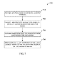
- FIG. 7 presents a flowchart of an example of a method 700 for managing optical noise in optical spectroscopy in accordance with at least certain aspects of the disclosure.
- an enclosure containing a group of media can be provided.
- providing such an enclosure can include providing a compartment of an optical spectroscopy analyzer, where the compartment can contain the at least one medium of the group of media.
- the group of media can include one or more solid, one or more fluids, some combination thereof, or the like.
- the enclosure and/or a compartment thereof can be substantially hermetically sealed, and the group of media can include at least one transparent medium (e.g., a transparent solid, a transparent fluid, a combination thereof, or the like) and/or at least one semi-transparent medium (e.g., a semi-transparent solid, a semi-transparent fluid, a combination thereof, or the like).
- the group of media can include at least one transparent medium (e.g., a transparent solid, a transparent fluid, a combination thereof, or the like) and/or at least one semi-transparent medium (e.g., a semi-transparent solid, a semi-transparent fluid, a combination thereof, or the like).
- the respective refractive index of at least one medium of the group of media can be modified.
- such a refractive index can be modified in multiple different ways based in part on the at least one medium.
- the respective refractive index of the gas can be modified by modifying the pressure of the fluid as a function of time.
- the refractive index of the solid can be modified by applying a mechanical stress or strain to the solid as a function of time, and/or by heating or cooling the solid as a function of time.
- the respective refractive index of the at least one medium of the group of media can be modified by modulating (e.g., modifying over a time) a stimulus that may be exerted on the at least one medium.
- Modulating the time-dependent stimulus applied to the at least one media can be achieved in many different ways, including modifying a pressure of the at least one of the one or more media; applying a mechanical strain to the at least one medium; applying a mechanical stress to the at least one medium; and/or modifying a temperature of the at least one medium.
- modifying the pressure of the at least one medium of the group of media can include periodically switching a pressure of a fluid from a first pressure to a second pressure.
- light output can be generated via a light source (e.g., a gas-discharge lamp, a tunable laser, or the like) disposed or otherwise contained in the enclosure.
- a light source e.g., a gas-discharge lamp, a tunable laser, or the like
- the light output can be utilized or otherwise leveraged to conduct optical spectroscopy (such as optical absorption spectroscopy, optical emission spectroscopy, or the like).
- optical spectroscopy such as optical absorption spectroscopy, optical emission spectroscopy, or the like.
- modification of the respective refractive index of the at least one medium of the group of media can permit mitigation of optical noise according to aspects of this disclosure.
- at least a portion of the light output can be propagated through the at least one medium of the group of media.
- Embodiments of the disclosure may be entirely or partially embodied in hardware, software, or a combination of the two (e.g., a firmware embodiment).
- various embodiments of the disclosure e.g., methods and systems
- may take the form of a computer program product comprising a computer-readable non-transitory storage medium having computer-accessible instructions (e.g., computer-readable and/or computer-executable instructions) such as computer software, encoded or otherwise embodied in such storage medium.
- Those instructions can be read or otherwise accessed and executed by one or more processors to perform or permit performance of the operations described herein.
- the instructions can be provided in any suitable form, such as source code, compiled code, interpreted code, executable code, static code, dynamic code, assembler code, combinations of the foregoing, and the like.
- Any suitable computer-readable non-transitory storage medium may be utilized to form the computer program product.
- the computer-readable medium may include any tangible non-transitory medium for storing information in a form readable or otherwise accessible by one or more computers or processor(s) functionally coupled thereto.
- Non-transitory storage media can include read only memory (ROM); random access memory (RAM); magnetic disk storage media; optical storage media; flash memory, etc.
- Embodiments of the operational environments and techniques are described herein with reference to block diagrams and flowchart illustrations of methods, systems, apparatuses, and computer program products. It can be understood that each block of the block diagrams and flowchart illustrations, and combinations of blocks in the block diagrams and flowchart illustrations, respectively, can be implemented by computer-accessible instructions.
- the computer-accessible instructions may be loaded or otherwise incorporated into onto a general purpose computer, special purpose computer, or other programmable information processing apparatus to produce a particular machine, such that the operations or functions specified in flowchart block(s) can be implemented in response to execution at the computer or processing apparatus.
- ком ⁇ онент As used herein, the terms “component,” “environment,” “system,” “platform,” “architecture,” “interface,” “unit,” “module,” and the like are intended to refer to a computer-related entity or an entity related to an operational apparatus with one or more specific functionalities. Such entities may be either hardware, a combination of hardware and software, software, or software in execution.
- a component may be, but is not limited to being, a process running on a processor, a processor, an object, an executable portion of software, a thread of execution, a program, and/or a computing device.
- a software application executing on a computing device and the computing device can be a component.
- One or more components may reside within a process and/or thread of execution.
- a component may be localized on one computing device or distributed between two or more computing devices.
- a component can execute from various computer-readable non-transitory media having various data structures stored thereon.
- a component can be an apparatus that provides specific functionality through electronic components without mechanical parts, the electronic components can include a processor therein to execute software or firmware that confers at least in part the functionality of the electronic components.
- a component can be an apparatus that provides specific functionality by means of mechanical parts without reliance on electronic or electromechanical parts.
- a component can be an apparatus with specific functionality provided by mechanical parts, electrical parts, and/or electromechanical parts operated by electric or electronic circuitry that can be controlled by a software application or firmware application executed by a processor, wherein the processor can be internal or external to the apparatus and can execute at least a part of the software or firmware application.
- components can communicate via local and/or remote processes in accordance, for example, with a signal (either analog or digital) having one or more data packets (e.g., data from one component interacting with another component in a local system, distributed system, and/or across a network such as a wide area network with other systems via the signal).
- components can communicate or otherwise be coupled via thermal, mechanical, electrical, and/or electromechanical coupling mechanisms (such as conduits, connectors, combinations thereof, or the like).
- An interface can include input/output (I/O) components as well as associated processor, application, and/or other programming components.
- I/O input/output
- the terms “component,” “environment,” “system,” “platform,” “architecture,” “interface,” “unit,” and “module” can be utilized interchangeably and can be referred to collectively as functional elements.
- a processor can refer to, for example, any computer processing unit or device having single-core processors; single-processors with software multithread execution capability; multi-core processors; multi-core processors with software multithread execution capability; multi-core processors with hardware multithread technology; parallel platforms; and parallel platforms with distributed, shared memory.
- a processor can refer to an integrated circuit (IC), an application-specific integrated circuit (ASIC), a digital signal processor (DSP), a field programmable gate array (FPGA), a programmable logic controller (PLC), a complex programmable logic device (CPLD), a discrete gate or transistor logic, discrete hardware components, or any combination thereof designed to perform the functions described herein.
- a processor can be implemented as a combination of computer processing units.
- processors can utilize nanoscale architectures such as, but not limited to, molecular and quantum-dot based transistors, switches and gates, in order to optimize space usage or enhance performance of user equipment.
- the memory components or memories described herein embody or include non-transitory computer storage media that can be readable or otherwise accessible by a computing device. Such media can be implemented in any methods or technology for storage of information such as computer-readable instructions, information structures, program modules, or other information objects.
- the memory components or memories can be either volatile memory or non-volatile memory, or can include both volatile and non-volatile memory.
- the memory components or memories can be removable or non-removable, and/or internal or external to a computing device or component.
- non-transitory storage media can include hard-disc drives, zip drives, CD-ROMs, digital versatile disks (DVD) or other optical storage, magnetic cassettes, magnetic tapes, magnetic disk storage or other magnetic storage devices, flash memory cards or other types of memory cards, cartridges, or any other non-transitory medium suitable to retain the desired electronic information and which can be accessed by a computing device.
- non-volatile memory can include read only memory (ROM), programmable ROM (PROM), electrically programmable ROM (EPROM), electrically erasable ROM (EEPROM), or flash memory.
- Volatile memory can include random access memory (RAM), which acts as external cache memory.
- RAM is available in many forms such as synchronous RAM (SRAM), dynamic RAM (DRAM), synchronous DRAM (SDRAM), double data rate SDRAM (DDR SDRAM), enhanced SDRAM (ESDRAM), Synchlink DRAM (SLDRAM), and direct Rambus RAM (DRRAM).
- SRAM synchronous RAM
- DRAM dynamic RAM
- SDRAM synchronous DRAM
- DDR SDRAM double data rate SDRAM
- ESDRAM enhanced SDRAM
- SLDRAM Synchlink DRAM
- DRRAM direct Rambus RAM
- conditional language such as, among others, “can,” “could,” “might,” or “may,” unless specifically stated otherwise, or otherwise understood within the context as used, is generally intended to convey that certain implementations could include, while other implementations do not include, certain features, elements, and/or operations. Thus, such conditional language generally is not intended to imply that features, elements, and/or operations are in any way required for one or more implementations or that one or more implementations necessarily include logic for deciding, with or without user input or prompting, whether these features, elements, and/or operations are included or are to be performed in any particular implementation.
Landscapes
- Physics & Mathematics (AREA)
- Spectroscopy & Molecular Physics (AREA)
- Nonlinear Science (AREA)
- General Physics & Mathematics (AREA)
- Optics & Photonics (AREA)
- Investigating Or Analysing Materials By Optical Means (AREA)
- Spectrometry And Color Measurement (AREA)
Abstract
Description
- Aspects of the disclosure relate generally to optical spectroscopy and more specifically to noise management in optical spectroscopy.
- Certain branches of analytical spectroscopy can rely on optical spectroscopy to observe and study the chemistry of fluids (e.g., presence of CO2, H2O, or other compounds) and/or the dynamics of chemical reactions (such as oxidation and/or combustion). In general, optical noise arising from optical interference between different pathways for light propagation within the equipment utilized for the optical spectroscopy is often the primary sensitivity-limiting factor in such spectroscopy. Conventional solutions to suppress the optical noise are typically prohibitively expensive, cumbersome to implement, and/or limited to current generation equipment, without a backwards compatible implementation.
- Aspects of the disclosure include suppression of optical interference fringes in optical spectra via a modification to the refractive index of media that forms or is contained in one or more components of equipment utilized for optical spectroscopy. Such a modification can yield changes in the optical path of light propagating through at least one of the media, with the ensuing changes in the spectral structure of interference between light propagating through different optical paths. In certain embodiments, the refractive index of the media that forms or is contained in one or more components can be modified via application of a time-dependent stimulus to at least one of the one or more components. The applied stimulus can include pressure, mechanical strain or stress, temperature, a combination thereof, or the like.
- The accompanying drawings are an integral part of the disclosure and are incorporated into the present specification. The drawings illustrate examples of embodiments of the disclosure and, in conjunction with the description and claims, serve to explain, at least in part, various principles, features, or aspects of the disclosure. Certain embodiments of the disclosure are described more fully below with reference to the accompanying drawings. However, various aspects of the disclosure can be implemented in many different forms and should not be construed as being limited to the implementations set forth herein. Like numbers refer to like, but not necessarily the same or identical, elements throughout.
-
FIG. 1 presents an example of an equipment component in accordance with one or more aspects of the disclosure. -
FIG. 2 illustrates optical paths of light propagating within an equipment component in accordance with at least certain aspects of the disclosure. -
FIG. 3 presents an example of a time dependent stimulus for management of optical noise in optical spectroscopy in accordance with at least certain aspects of the disclosure. -
FIGs. 4-5 depict example apparatuses for management of optical noise in optical spectroscopy in accordance with at least certain aspects of the disclosure. -
FIG. 6 presents an example of another apparatus for management of optical noise in optical spectroscopy in accordance with at least certain aspects of the disclosure. -
FIG. 7 presents an example of a technique for management of optical noise in optical spectroscopy in accordance with at least certain aspects of the disclosure. - The disclosure recognizes and addresses, in at least certain aspects, the issue of optical noise in analytical spectroscopy. The disclosure provides devices, systems, and/or techniques for management (e.g., reduction and/or control) of optical noise in optical spectroscopy. As described in greater detail below, in at least certain aspects, the disclosure permits suppression of optical interference fringes in optical spectra via a modification to the refractive index of media that forms or is contained in one or more components of equipment utilized for optical spectroscopy. Such a modification can yield changes in the optical path of light propagating through at least one of the media, with the ensuing changes in the spectroscopy structure of interference between light propagating through different optical paths. The media can include transparent or semi-transparent materials (either solids, fluids (such as, liquid, gas, or a combination thereof), or combinations thereof). In certain embodiments, the refractive index of the media that forms or is contained in one or more components can be modified via application of a time-dependent stimulus (periodic or otherwise) to at least one of the one or more components. The applied stimulus can include pressure, mechanical strain or stress, temperature, a combination thereof, or the like. In addition, at least in certain embodiments, application of the stimulus can be implemented via passive control components, such as pneumatic components without active control.
- Various aspects of the disclosure are illustrated in connection with optical spectroscopy equipment and modulation of refractive index of a gas therein via modulation of the pressure of the gas. Yet, it should be appreciated that the disclosure is not so restricted and permits management of optical noise in such equipment via modulation of the refractive index of gas contained in the equipment and/or optical elements therein via application of a time-dependent stimulus (e.g., time-dependent pressure, strain, and/or temperature). The principles of the disclosure generally can be applied to substantially any enclosure containing a gas and/or optical element(s) that are part of optical spectroscopy equipment.
- One example advantage may include simplicity of implementation and cost efficiency. With reference to the drawings,
FIG. 1 presents an example of anequipment component 110 in accordance with at least certain aspects of the disclosure. In certain embodiments, theequipment component 110 can be embodied in or can include an enclosure of an optical spectroscopy analyzer. Such an enclosure can include one or more compartments, where at least one of the one or more compartments can be substantially hermetic or otherwise sealed. In other embodiments, theequipment component 110 can be embodied in or can include an optical element (e.g., a lens, a window, or the like) of the optical spectroscopy analyzer. In yet other embodiments, theequipment component 110 can be embodied in or can include a combination of an enclosure and a group of optical members of the optical spectroscopy analyzer. In addition, theequipment component 110 can contain a solid, a fluid (such as a liquid or gas) or a mixture thereof, and can include afirst surface 120a and asecond surface 120b and a space (e.g., separation) between thefirst surface 120a and thesecond surface 120b. As an illustration, theequipment component 110 can be a compartment of the optical spectroscopy equipment, such as a tunable diode laser spectroscopy (TDLS) analyzer, and can contain the gas, the fluid (such as a gas or liquid) or the mixture thereof that can be probed via such equipment. In the alternative, theequipment component 110 can be an optical element (which also may be referred to as an optical member) of the optical spectroscopy equipment. For example, as described herein, the optical element can be a lens (e.g., a meniscus, an aspheric lens, or the like), or a transparent or semi-transparent window. Such a lens or window can be solid or can include a mixture of a solid and a fluid. Further, theequipment component 110 can include a combination of one or more compartments and/or one or more optical members. More specifically, yet not exclusively, theequipment component 110 can include a compartment having a light source of the optical spectroscopy equipment (e.g., a gas-discharge lamp or a laser), a collimating lens, and a propagation window (as best shown inFIG. 5 discussed herein), where the compartment contains a fluid (such as a gas, liquid, or some combination thereof). - The
equipment component 110 can be configured (e.g., assembled or mounted) to receive light having a frequency (v) and intensity (I0 ), and can permit propagation of the received light. The received light can be utilized or otherwise leveraged to probe a material (e.g., a solid, a gas, a liquid, or a mixture thereof) via the optical spectroscopy equipment that includes theequipment component 110. As described herein, in certain embodiments, such a material can be contained within theequipment component 110. While the intensity I0 can depend on the frequency ν (or wavelength), in certain embodiments, such a dependency can be weak, yielding an approximately constant intensity over a range of frequencies. The light that is received can be substantially monochromatic (visible or otherwise) or can be composed of multiple frequencies within the visible or non-visible range of the electromagnetic spectrum. As illustrated, the light can be received at thesurface 120a and can propagate trough theequipment component 110, exiting through thesurface 120b. It can be readily apparent that thesurfaces - The light that propagates through the
equipment component 110 can have an intensity I(v) that can depend on frequency. Without intending to be bound or otherwise limited by theory and/or modeling, in one aspect, such dependency can be attributed to a signal Is (v) substantially originated in the optical absorption spectrum of a material contained in or that forms theequipment component 110, and optical noise ξ(v) substantially originated from optical interference between light that propagates from thefirst surface 120a to thesecond surface 120b through different optical paths. The optical interference may be referred to as "etalon effect" and generally yields fringes of optical interference associated with alternating maxima and minima of intensity, or strength, of the optical noise ξ(v). The optical interference fringes may be referred to as "etalons," and such maxima and minima can arise from constructive interference and destructive interference between light that propagates through different optical paths betweensurfaces - Without intending to be bound or otherwise limited by geometric optics theory,
FIG. 2 illustrates two optical paths betweensurfaces optical path 210 in which light propagates directly from thefirst surface 120a to thesecond surface 120b; and a secondoptical path 220 in which light propagates from thefirst surface 120a to thesecond surface 120b, reflects off thesecond surface 120b and propagates to thefirst surface 120a, and reflects off thefirst surface 120a and propagates back to thesecond surface 120b. The firstoptical path 210 and second optical path 120 are represented with lines of different thickness, and have optical distances d · n and 2d · n, respectively, where d represents the distance between thefirst surface 120a and thesecond surface 120b, and n represents the refractive index of the medium (e.g., a solid, a fluid, or a combination thereof) contained within such surfaces. As illustrated, in one aspect, the refractive index can depend on frequency of light (v) and time (t): n = n(v, t). The optical distance d · n can determine the period of the spacing between optical interference fringes, where maxima (e.g., constructive interference) occurs when the following condition is satisfied: 2d · n = mλ, where m is a natural number and λ = c/v is the vacuum wavelength of the light, and where c is the speed of light in vacuum. Accordingly, a change in optical distance matching a quarter wavelength can cause a transition from constructive interference to destructive interference. Put simply, when the condition Δ(d · n) = λ/4 is satisfied, the strength of optical noise can transition from a maximum to a minimum. Accordingly, in one aspect, control of changes in the optical distance via modification of the refractive index of a medium that composes theequipment component 110 can permit management of the optical noise in optical spectroscopy. - It can be readily appreciated that, in one aspect, while the signal Is (v) can permit analyzing or otherwise probing a material contained in or that forms the
equipment component 110, the optical noise ξ(v) typically distorts the observed intensity I(v), and thus, the optical noise can mar the analysis. Such analysis can include chemical analysis based at least in part on the spectroscopic features of I(v). Accordingly, at least to mitigate the optical noise, theequipment component 110 can be submitted to a time-dependent stimulus ζ(t) that can modify the refractive index of the material contained in or that forms theequipment component 110. The stimulus can include pressure, mechanical strain or stress, temperature, a combination thereof, or the like. In one aspect, time-dependent modification of the refractive index of a material can occur in time scale greater than the time scale associated with modification of the refractive index via application of pressure. As illustrated inFIG. 1 , in response to application of the stimulus ζ(t) (which is pictorially represented with an arrow), such a refractive index can depend on light frequency (or wavelength) and time, which can cause an optical path of light propagating within theequipment component 110 to be time-dependent as well. In such a scenario, n = n(v, t) (where as described herein, n represents the refractive index of a medium contained in or that forms theequipment component 110, v represents the frequency of light that propagates within theequipment component 110, and t represents time) and the optical path can be expressed as·n(v,t), where is a geometric distance between two surfaces within the equipment component 110 (e.g.,
 can be the distance between the
first surface 120a and thesecond surface 120b). A time-dependent optical path can yield a time-dependent optical noise ξ(v,t) (where ξ represents time-dependent optical noise), and the intensity of light that is transmitted through thesurface 120b can be expressed as I(v) = Is (v) + ξ(v, t) (where I represents the intensity of light transmitted through thesurface 120b, Is represents the intensity of the signal originated in the optical absorption spectrum of a material contained in or that forms theequipment component 110, and v represents frequency of light). For a stimulus ζ(v, t) (where ζ represents the magnitude of the stimulus, v represents frequency of light, and t represents time) having strength (or magnitude) that varies between a first value (e.g., a lower bound) and a second value (e.g., an upper bound), measurement of I(v) over a time scale that is longer that the time scale in which the stimulus changes from the first value to the second value can mitigate the optical noise present in the observed I(v) . More specifically, yet not exclusively, for a stimulus that periodically varies from ζlow to ζhigh , measurement of I(v) over an interval greater than the period of the change between ζlow to ζhigh can mitigate the presence of optical noise in the observed I(v). Such an interval may be referred to as the integration time of the measurement of I(v). More specifically, yet not exclusively, a suitable integration period can permit averaging multiple scans (or measurements) of I(v) and thus suppressing the contribution of the time-dependent optical noise ξ(v, t) over time. Such suppression represents, in one aspect, a form of management of the optical noise. In addition, without intending to be bound or otherwise limited by theory and/or modeling, such a suppression of the time-dependent optical noise can originate from different strengths of the optical noise at a frequency v over time-e.g., the optical noise at the frequency v can transition between high strength (e.g., constructive interference maximum) and low strength (e.g., destructive interference minimum) over time. As illustrated inFIG. 3 , in certain implementations, the stimulus ζ(t) 130 (where ζ represents stimulus and t represents time) can vary periodically from ζlow to ζhigh according to a specific waveform. Although a sawtooth waveform is shown inFIG. 3 , other waveforms (e.g., triangular, sinusoidal, square, ...) can be contemplated. In other implementations, the stimulus ζ(t) can vary aperiodically from ζlow to ζhigh. - In certain embodiments, as illustrated in
FIG. 4 , for example, one or more perturbation units 410 (which may be referred to as perturbation unit(s) 410) can provide, at least in part, the stimulus ζ(t) 130. To at least such an end, at least one of the perturbation unit(s) 410 can be communicatively, fixedly, removably, mechanically, electrically, electromechanically, and/or thermally coupled to theequipment component 110 via one ormore coupling members 420. Based at least on the type of stimulus that is applied, a coupling member can be embodied in or can include a pipe, a flange, an inlet, a thermally conductive element, an electrically conductive element, a combination thereof, or the like. In certain embodiments, the perturbation unit(s) 410 can include at least one unit that can provide the stimulus-e.g., a pneumatic valve, a piston, a bellow, a heating element, a thermoelectric component, and/or a component to apply a mechanical strain/stress-and at least one unit that can control the application of the stimulus. Such a unit can be embodied in or can include an electronic controller having a processor that can execute instructions (e.g., computer-accessible instructions) retained in a memory device in order to cause the application of at least part of the stimulus via the at least one unit that can provide the stimulus. In addition, in certain embodiments, the at least one unit that can control the application of the stimulus can include a mechanism (e.g., an electronic or mechanic timer) that can regulate electronically and/or mechanically the operation of the at least one unit that can provide the stimulus (e.g., implementation of an open-shut cycle of a valve). Further, in other embodiments, the at least one unit that can control the at least one unit that can provide the stimulus can include an external pneumatic controller or an electronic controller (which can be embodied in or can include a processing unit or a processor). Accordingly, in one aspect, such embodiments may be referred to as active control embodiments. - In addition or in the alternative, the perturbation unit(s) 410 can include at least one unit that can provide the stimulus, and can passively control the application thereof. In certain embodiments, mechanism(s) and/or controller(s) can be integrated into or otherwise combined or included with the at least one unit that can provide the stimulus (e.g., a passive pneumatic system). Thus, in one aspect, such embodiments may be referred to as passive control embodiments. It should be appreciated that passive control embodiments can provide simplicity, reliability, and/or can permit cost management of the application of the stimulus in accordance with aspects of the disclosure.
- In certain scenarios, the stimulus ζ(t) can be applied by heating or cooling a material that embodies or that is contained in the
equipment component 110, or by applying a mechanical stress or strain to such material. For instance, in an embodiment in which theequipment component 110 is embodied in an optical member (e.g., a lens, a window, etc.), optical noise originating from interference between light propagation between two surfaces of the optical member can be mitigated by (a) heating or cooling the optical member, and/or (b) applying a mechanical stress or strain to the optical member in order to modify the optical member's refractive index. - In scenarios in which the stimulus ζ(t) is pressure, at least one of the perturbation unit(s) 410 and at least one of the
coupling members 420 can permit modifying the pressure applied to theequipment component 110 as a function of time. Put more simply, ζ(t) = P(t), where P(t) is a function of time indicative or otherwise representative of the pressure applied to theequipment component 110. In one of such scenarios, theequipment component 110 can contain a gas, such as a noble gas or a substantially inert gas. For instance, theequipment component 110 can be embodied in a compartment of an optical spectroscopy analyzer. Without intending to be bound or otherwise limited by theory and/or modeling, the refractive index ng of a gas may be approximated as ng - 1 = C · N, where C is a gas-specific parameter that depends on wavelength, and N is a concentration of gas molecules that depends on temperature (T) and pressure (P). In addition, the index of refraction nTP of air at a specific temperature and pressure P may be expressed as
where T and P are measured, respectively, in degrees Celsius (°C) and pascals (Pa), and ns is the index of refraction of dry air at 15 °C and 101325 Pa, and containing 0.045 % by volume of carbon dioxide. As it can be readily gleaned from the foregoing equation, at constant temperature T, the refractive index shift Δn = nTP - ns is nearly directly proportional to the pressure P. It should be appreciated that, in one aspect, the refractive index ns can exhibit dispersion (e.g., it can vary with wavelength). For example, without intending to be bound or otherwise limited by theory or modeling, the dispersion of the refractive index ns can be represented by the following relationship:

- For the refractive index shift Δn and light wavelength λ, the minimum distance dmin for which constructive interference can be changed to destructive interference can be determined via the following condition:
- As described herein, in certain aspects, transitions between constructive interference and destructive interference can permit management of optical noise in optical spectroscopy. As an illustration, for light having a wavelength λ = 760 nm and a refractive index shift Δn ≅ 0.0003, which can be achieved by a change in gas pressure of about 101325 Pa (e.g., about 1 atm), the value of dmin can be determined as follows:

- Without intending to be bound or otherwise limited by theory and/or modeling, the minimum change in pressure (ΔP min ) to avoid optical interference fringes due to constructive interference can be determined via the following relationship:

where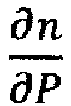

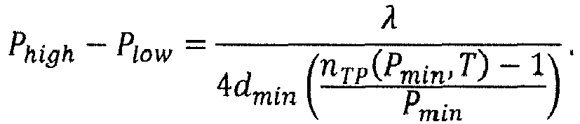
- Based at least on the illustrative analysis described herein, it can be readily apparent that in at least certain scenarios, ranges for the magnitude of the stimulus can be determined a priori, which can permit design of suitable stimuli in order to manage optical noise in optical spectroscopy.
- In addition, it should be appreciated that the manner in which pressure is applied can be based at least in part on the
equipment component 110. For example, in an embodiment in which theequipment component 110 is embodied in a compartment or enclosure of the optical spectroscopy equipment, pressure can be applied to the fluid (e.g., a gas, liquid or combination thereof) that can be contained in such compartment or enclosure. To at least such an end, in one implementation, the at least one of the perturbation unit(s) 410 can permit (A) injection of fluid into the compartment or enclosure in order to increase the pressure of the fluid therein from a first pressure (e.g., Plow ) to a second pressure (e.g., Phigh ) over a predetermined time interval, and (B) release of fluid from the compartment or enclosure in order to decrease the pressure from the second pressure (e.g., Phigh ) to the first pressure (e.g., Plow ) over another predetermined interval. The injection-release cycle can be repeated in order to produce a periodic modification of the pressure within theequipment component 110. It should be appreciated that other function P(t) can be implemented in other embodiments of this disclosure, where P represents the magnitude of pressure and t represents time, and where such a function can provide a periodic or aperiodic variation of pressure of the medium contained in or that forms theequipment component 110. - As an illustration,
FIG. 5 presents a block diagram of anexample embodiment 500 of theequipment component 110, the coupling member(s) 420, and the perturbation unit(s) 410 in accordance with at least certain aspects of the disclosure. For the sake of simplicity, the functional elements in the illustrated block diagram are shown in a cross-section representation. As illustrated, theequipment component 510 is embodied in an enclosure having acompartment 520 of the optical spectroscopy equipment, and aninlet conduit 560 providing a fluidic pathway between thecompartment 520 and the exterior of theequipment component 510. Thecompartment 520 can include additional equipment components, such as alight source 530, an optical member 540 (e.g., a collimating lens), and a second optical member 550 (e.g., a window formed of a transparent or semi-transparent material, such as fused silica or other glass). Thelight source 530 can be embodied in or can include gas-discharge lamp or a tunable laser (such as a diode laser, a CO2 laser, a dye laser, or a transition-metal solid-state laser) that can provide light (visible or otherwise) having wavelengths in a predetermined portion of the electromagnetic spectrum. Theinlet conduit 560 permits injection of gas (e.g., instrument gas, nitrogen, or a noble gas) into thecompartment 520. A gas source (not depicted inFIG. 5 ) can supply a substantially constant flow of the gas, which may be referred to as purge gas. - In addition, with reference to the
example embodiment 400 ofFIG. 4 , the coupling member(s) 420 can be embodied in anoutlet conduit 570 providing a fluidic pathway out of thecompartment 520, which is coupled directly and/or fluidically to avalve 580 embodying the perturbation unit(s) 410. Thevalve 580 may be referred to as "modulating valve," and, in one aspect, can be embodied in a pneumatic valve configured to receive pressurized or otherwise compressed gas from thecompartment 520 via theoutlet conduit 570. In one aspect, thevalve 580 can be configured to open at about a first pressure (e.g., Phigh ) and shut at about a second pressure (e.g., Plow ) that is lower than the first pressure, thereby producing a substantially periodic variation of the pressure of the gas contained in thecompartment 520. (See, e.g.,FIG. 3 ). It should be appreciated that, in certain embodiments, the modulatingvalve 580 can be configured to produce substantially any periodic variation of pressure (e.g., a square waveform, a triangular waveform, a sinusoidal waveform, or the like) or time-dependent pressure profile (periodic or aperiodic). In certain embodiments, a mechanism (e.g., an electronic or mechanical timer) can regulate electronically and/or mechanically the operation of the valve 580 (e.g., implementation of an open-shut cycle), which can produce a predetermined or otherwise intended pressure profile in thecompartment 520. In other embodiments, an external pneumatic or electronic controller (which can be embodied in or can include a computer or processing unit) can regulate the operation of the modulatingvalve 580. In theexample embodiment compartment 520 can yield a time-dependent variation of the refractive index of such gas, with the ensuing mitigation of optical noise on the intensity of light emanating from theoptical member 550. As described herein, in one aspect, the optical noise can include optical interference fringes of constructive interference between light that propagates between a pair of surfaces through difference optical paths. Such fringes also may be referred to as "etalons," and can include etalons originating from light propagation between thelight source 530 and the optical element 540 (referred to as "lens-light-source" etalons); theoptical element 540 and the optical element 550 (referred to as "window-lens" etalons); and thelight source 530 and the optical element 550 (referred to as "window-light-source" etalons). For a modulatingvalve 580 that can provide a sufficiently large range of variation between the a first pressure (e.g., Phigh ) and a lower second pressure (e.g., Plow ), substantially all free-space etalons in thecompartment 410 can be averaged out or otherwise removed over time during measurement of the intensity of light propagating through theoptical member 550. - In addition, the disclosure can permit mitigation of optical noise due to optical interference via time-dependent modification of the refractive index of substantially any component of an optical spectroscopy analyzer, including the light-source compartment, a detector compartment, a sample cell or chamber, or a combination thereof. To at least such an end, in one aspect, a group of equipment components can be subject to respective stimuli at least in order to effect a time-dependent variation of the respective refractive index of such components. As an illustration,
FIG. 6 presents threeequipment components 610a-610c that can be submitted torespective stimuli 620a-620c in order to modify the respective refractive indices as a function of time, thereby producing refractive indices na (v, t), nb (v, t), and nc (v, t), with the ensuing mitigation of optical noise in accordance with aspects described herein. - In view of the aspects described herein, examples of a technique for management of optical noise in optical spectroscopy in accordance with at least certain aspects of the disclosure can be better appreciated with reference to the diagram in
FIG. 7 . For purposes of simplicity of explanation, the examples of the techniques disclosed herein are presented and described as a series of blocks, with each block representing an action or an operation in a method, for example. However, it is to be understood and appreciated that the disclosed techniques (e.g., process(es), procedure(s), method(s), and the like) are not limited by the order of blocks and associated actions or operations, as some blocks may occur in different orders and/or concurrently with other blocks from that are shown and described herein. For example, the various techniques of the disclosure can be alternatively represented as a series of interrelated states or events, such as in a state diagram. Furthermore, not all illustrated blocks, and associated action(s) or operation(s), may be required to implement a technique in accordance with one or more aspects of the disclosure. Further yet, two or more of the disclosed techniques can be implemented in combination with each other, to accomplish one or more features and/or advantages described herein. - It should be appreciated that, in certain embodiments, at least a portion of the techniques of the disclosure can be retained on an article of manufacture, or computer-readable storage medium in order to permit or facilitate transporting and transferring such techniques to a computing device (such as a microcontroller, a programmable logic controller, a programmable logic relay, and the like) for execution, and thus implementation, by a processor of the computing device or for storage in a memory thereof or functionally coupled thereto. In one aspect, one or more processors, such as processor(s) that implement (e.g., execute) one or more of the disclosed techniques, can be employed to execute instructions retained in a memory, or any computer- or machine-readable storage medium, to implement the techniques described herein. The instructions can embody or can constitute at least a portion of the techniques, and thus can provide a computer-executable or machine-executable framework to implement the techniques described herein.
-
FIG. 7 presents a flowchart of an example of amethod 700 for managing optical noise in optical spectroscopy in accordance with at least certain aspects of the disclosure. Atblock 710, an enclosure containing a group of media can be provided. As described herein, in one aspect, providing such an enclosure can include providing a compartment of an optical spectroscopy analyzer, where the compartment can contain the at least one medium of the group of media. The group of media can include one or more solid, one or more fluids, some combination thereof, or the like. More particularly, yet not exclusively, in certain implementations, the enclosure and/or a compartment thereof can be substantially hermetically sealed, and the group of media can include at least one transparent medium (e.g., a transparent solid, a transparent fluid, a combination thereof, or the like) and/or at least one semi-transparent medium (e.g., a semi-transparent solid, a semi-transparent fluid, a combination thereof, or the like). - At
block 720, the respective refractive index of at least one medium of the group of media can be modified. As described herein, in certain embodiments, such a refractive index can be modified in multiple different ways based in part on the at least one medium. For example, in an embodiment in which the at least one medium includes a fluid, the respective refractive index of the gas can be modified by modifying the pressure of the fluid as a function of time. For another example, in an embodiment in which the at least one medium includes a solid, the refractive index of the solid can be modified by applying a mechanical stress or strain to the solid as a function of time, and/or by heating or cooling the solid as a function of time. More generally, as described herein, the respective refractive index of the at least one medium of the group of media can be modified by modulating (e.g., modifying over a time) a stimulus that may be exerted on the at least one medium. Modulating the time-dependent stimulus applied to the at least one media can be achieved in many different ways, including modifying a pressure of the at least one of the one or more media; applying a mechanical strain to the at least one medium; applying a mechanical stress to the at least one medium; and/or modifying a temperature of the at least one medium. In one aspect, modifying the pressure of the at least one medium of the group of media can include periodically switching a pressure of a fluid from a first pressure to a second pressure. - At
block 730, light output can be generated via a light source (e.g., a gas-discharge lamp, a tunable laser, or the like) disposed or otherwise contained in the enclosure. As described herein, the light output can be utilized or otherwise leveraged to conduct optical spectroscopy (such as optical absorption spectroscopy, optical emission spectroscopy, or the like). In addition, modification of the respective refractive index of the at least one medium of the group of media can permit mitigation of optical noise according to aspects of this disclosure. Atblock 740, at least a portion of the light output can be propagated through the at least one medium of the group of media. - Embodiments of the disclosure may be entirely or partially embodied in hardware, software, or a combination of the two (e.g., a firmware embodiment). Furthermore, as described herein, various embodiments of the disclosure (e.g., methods and systems) may take the form of a computer program product comprising a computer-readable non-transitory storage medium having computer-accessible instructions (e.g., computer-readable and/or computer-executable instructions) such as computer software, encoded or otherwise embodied in such storage medium. Those instructions can be read or otherwise accessed and executed by one or more processors to perform or permit performance of the operations described herein. The instructions can be provided in any suitable form, such as source code, compiled code, interpreted code, executable code, static code, dynamic code, assembler code, combinations of the foregoing, and the like. Any suitable computer-readable non-transitory storage medium may be utilized to form the computer program product. For instance, the computer-readable medium may include any tangible non-transitory medium for storing information in a form readable or otherwise accessible by one or more computers or processor(s) functionally coupled thereto. Non-transitory storage media can include read only memory (ROM); random access memory (RAM); magnetic disk storage media; optical storage media; flash memory, etc.
- Embodiments of the operational environments and techniques (procedures, methods, processes, and the like) are described herein with reference to block diagrams and flowchart illustrations of methods, systems, apparatuses, and computer program products. It can be understood that each block of the block diagrams and flowchart illustrations, and combinations of blocks in the block diagrams and flowchart illustrations, respectively, can be implemented by computer-accessible instructions. In certain implementations, the computer-accessible instructions may be loaded or otherwise incorporated into onto a general purpose computer, special purpose computer, or other programmable information processing apparatus to produce a particular machine, such that the operations or functions specified in flowchart block(s) can be implemented in response to execution at the computer or processing apparatus.
- Unless otherwise expressly stated, it is in no way intended that any technique, protocol, procedure, process, or method set forth herein be construed as requiring that its acts, operations, or steps be performed in a specific order. Accordingly, where a process or method claim does not actually recite an order to be followed by its acts, operations, or steps, or it is not otherwise specifically recited in the claims or descriptions of the subject disclosure that the steps are to be limited to a specific order, it is in no way intended that an order be inferred, in any respect. This holds for any possible non-express basis for interpretation, including: matters of logic with respect to arrangement of steps or operational flow; plain meaning derived from grammatical organization or punctuation; the number or type of embodiments described in the specification or annexed drawings, or the like.
- As used herein, the terms "component," "environment," "system," "platform," "architecture," "interface," "unit," "module," and the like are intended to refer to a computer-related entity or an entity related to an operational apparatus with one or more specific functionalities. Such entities may be either hardware, a combination of hardware and software, software, or software in execution. As an example, a component may be, but is not limited to being, a process running on a processor, a processor, an object, an executable portion of software, a thread of execution, a program, and/or a computing device. For instance, both a software application executing on a computing device and the computing device can be a component. One or more components may reside within a process and/or thread of execution. A component may be localized on one computing device or distributed between two or more computing devices. A component can execute from various computer-readable non-transitory media having various data structures stored thereon. As another example, a component can be an apparatus that provides specific functionality through electronic components without mechanical parts, the electronic components can include a processor therein to execute software or firmware that confers at least in part the functionality of the electronic components. As yet another example, a component can be an apparatus that provides specific functionality by means of mechanical parts without reliance on electronic or electromechanical parts. As a further another example, a component can be an apparatus with specific functionality provided by mechanical parts, electrical parts, and/or electromechanical parts operated by electric or electronic circuitry that can be controlled by a software application or firmware application executed by a processor, wherein the processor can be internal or external to the apparatus and can execute at least a part of the software or firmware application. In certain embodiments, components can communicate via local and/or remote processes in accordance, for example, with a signal (either analog or digital) having one or more data packets (e.g., data from one component interacting with another component in a local system, distributed system, and/or across a network such as a wide area network with other systems via the signal). In other embodiments, components can communicate or otherwise be coupled via thermal, mechanical, electrical, and/or electromechanical coupling mechanisms (such as conduits, connectors, combinations thereof, or the like). An interface can include input/output (I/O) components as well as associated processor, application, and/or other programming components. The terms "component," "environment," "system," "platform," "architecture," "interface," "unit," and "module" can be utilized interchangeably and can be referred to collectively as functional elements.
- In the present specification and annexed drawings, reference to a "processor" is made. As utilized herein, a processor can refer to, for example, any computer processing unit or device having single-core processors; single-processors with software multithread execution capability; multi-core processors; multi-core processors with software multithread execution capability; multi-core processors with hardware multithread technology; parallel platforms; and parallel platforms with distributed, shared memory. Additionally, a processor can refer to an integrated circuit (IC), an application-specific integrated circuit (ASIC), a digital signal processor (DSP), a field programmable gate array (FPGA), a programmable logic controller (PLC), a complex programmable logic device (CPLD), a discrete gate or transistor logic, discrete hardware components, or any combination thereof designed to perform the functions described herein. As an example, a processor can be implemented as a combination of computer processing units. In certain embodiments, processors can utilize nanoscale architectures such as, but not limited to, molecular and quantum-dot based transistors, switches and gates, in order to optimize space usage or enhance performance of user equipment.
- In addition, in the present specification and annexed drawings, terms such as "store," storage," "data store," "data storage," "memory," "repository," and substantially any other information storage component relevant to operation and functionality of a component of the disclosure, refer to "memory components," entities embodied in a "memory," or components forming the memory. It can be appreciated that the memory components or memories described herein embody or include non-transitory computer storage media that can be readable or otherwise accessible by a computing device. Such media can be implemented in any methods or technology for storage of information such as computer-readable instructions, information structures, program modules, or other information objects. The memory components or memories can be either volatile memory or non-volatile memory, or can include both volatile and non-volatile memory. In addition, the memory components or memories can be removable or non-removable, and/or internal or external to a computing device or component. Examples of various types of non-transitory storage media can include hard-disc drives, zip drives, CD-ROMs, digital versatile disks (DVD) or other optical storage, magnetic cassettes, magnetic tapes, magnetic disk storage or other magnetic storage devices, flash memory cards or other types of memory cards, cartridges, or any other non-transitory medium suitable to retain the desired electronic information and which can be accessed by a computing device.
- As an illustration, non-volatile memory can include read only memory (ROM), programmable ROM (PROM), electrically programmable ROM (EPROM), electrically erasable ROM (EEPROM), or flash memory. Volatile memory can include random access memory (RAM), which acts as external cache memory. By way of illustration and not limitation, RAM is available in many forms such as synchronous RAM (SRAM), dynamic RAM (DRAM), synchronous DRAM (SDRAM), double data rate SDRAM (DDR SDRAM), enhanced SDRAM (ESDRAM), Synchlink DRAM (SLDRAM), and direct Rambus RAM (DRRAM). The disclosed memory components or memories of operational environments described herein are intended to include one or more of these and/or any other suitable types of memory.
- Conditional language, such as, among others, "can," "could," "might," or "may," unless specifically stated otherwise, or otherwise understood within the context as used, is generally intended to convey that certain implementations could include, while other implementations do not include, certain features, elements, and/or operations. Thus, such conditional language generally is not intended to imply that features, elements, and/or operations are in any way required for one or more implementations or that one or more implementations necessarily include logic for deciding, with or without user input or prompting, whether these features, elements, and/or operations are included or are to be performed in any particular implementation.
- The specification and annexed drawings disclose examples of systems, apparatuses, devices, techniques, and computer-program products that can provide management of optical noise in optical spectroscopy. It is, of course, not possible to describe every conceivable combination of elements and/or methods for purposes of describing the various features of the disclosure, but those of ordinary skill in the art recognize that many further combinations and permutations of the disclosed features are possible. Accordingly, various modifications can be made to the disclosure without departing from the scope or spirit thereof. In addition, or in the alternative, other embodiments of the disclosure may be apparent from consideration of the specification and annexed drawings, and practice of the disclosure as presented herein. It is intended that the examples put forward in the specification and annexed drawings be considered, in all respects, as illustrative and not restrictive. Although specific terms are employed herein, they are used in a generic and descriptive sense only and not for purposes of limitation.
Claims (20)
- A system for management of optical noise, comprising:means for containing one or more media;means for modifying a respective refractive index of at least one of the one or more media as a function of time; andmeans for producing light output, wherein at least a portion of the light output propagates through the at least one of the one or more media.
- The apparatus of Claim 1, wherein the means for containing the one or more media is substantially hermetically sealed, and
wherein the one or more media comprises one or more of a transparent medium or a semi-transparent medium. - The apparatus of Claim 1, wherein the means for containing the one or more media comprises means for containing one or more of a fluid or an optical member.
- The apparatus of Claim 1, wherein the means for modifying the respective refractive index of the at least one of the one or more media as a function of time comprises means for periodically modifying the respective refractive index of the at least one of the one or more media from a first value to a second value.
- The apparatus of Claim 1, wherein the means for modifying the respective refractive index of the at least one of the one or more media as a function of time comprises means for modifying a pressure of the at least one of the one or more media.
- The apparatus of Claim 5, wherein the means for modifying the pressure of the at least one of the one or more media comprises means for periodically switching a pressure of a fluid from a first pressure to a second pressure.
- The apparatus of Claim 1, wherein the means for modifying the respective refractive index of the at least one of the one or more media as a function of time comprises means for applying a mechanical stress to the at least one of the one or more media.
- The apparatus of Claim 7, wherein the means for applying the mechanical stress to the at least one of the one or more media comprises means for applying the mechanical stress to an optical member as a function of time.
- The apparatus of Claim 1, wherein the means for modifying the respective refractive index of the at least one of the one or more media as a function of time comprises means for modifying a temperature of the at least one of the one or more media.
- The apparatus of Claim 9, wherein the means for modifying the temperature of the at least one of the one or more media comprises means for heating a fluid as a function of time or means for cooling the fluid as a function of time.
- The apparatus of Claim 10, wherein the means for modifying the temperature of the at least one of the one or more media comprises means for heating an optical member as a function of time or means for cooling the optical member as a function of time.
- A method for management of optical noise, comprising:providing an enclosure containing one or more media;modifying a respective refractive index of at least one of the one or more media by modulating a time-dependent stimulus applied to the at least one of the one or more media;generating light output via a light source disposed in the enclosure; andpropagating at least a portion of the light output through the at least one of the one or more media.
- The method of Claim 12, wherein providing the enclosure containing the one or more media comprises providing a compartment containing at least one of the one or more media, and
wherein the compartment is substantially hermetically sealed, and
further wherein the one or more media comprises one or more of a transparent medium or a semi-transparent medium. - The method of Claim 12, wherein modulating the time-dependent stimulus applied to the at least one media comprises one or more of modifying a pressure of the at least one of the one or more media,
applying a mechanical strain to the at least one of the one or more media,
applying a mechanical stress to the at least one of the one or more media, or modifying a temperature of the at least one of the one or more media. - The method of Claim 14, wherein modifying the pressure of the at least one of the one or more media comprises periodically switching a pressure of a fluid from a first pressure to a second pressure.
- The method of Claim 12, wherein providing the enclosure containing the one or more media comprises providing a compartment of an optical spectroscopy analyzer, the compartment containing the at least one of the one or more media, and
wherein the at least one of the one or more media comprises a fluid. - An optical spectroscopy analyzer; comprising:a light source disposed within a substantially hermetically sealed enclosure;a group of optical members disposed within the enclosure, each optical member of the group of optical members disposed at a respective distance from the light source;a group of media contained within the enclosure, each medium of the group of media having a respective refractive index; anda group of perturbation units configured to modify as a function of time the respective refractive index of at least one medium of the group of media.
- The analyzer of Claim 17, wherein the group of media contained within the enclosure comprises at least one fluid.
- The analyzer of Claim 18, wherein the group of perturbation units comprises a modulation valve and a conduit fluidically coupled to both the modulation valve and the enclosure, the modulation valve is configured to modify substantially periodically a pressure of the at least one fluid as a function of time.
- The analyzer of Claim 18, wherein at least one unit of the group of perturbation units is configured to modify a temperature of the at least one fluid as a function of time.
Applications Claiming Priority (1)
| Application Number | Priority Date | Filing Date | Title |
|---|---|---|---|
| US14/247,526 US9746375B2 (en) | 2014-04-08 | 2014-04-08 | Systems, methods, and apparatus for optical noise management in optical spectroscopy |
Publications (2)
| Publication Number | Publication Date |
|---|---|
| EP2930481A1 true EP2930481A1 (en) | 2015-10-14 |
| EP2930481B1 EP2930481B1 (en) | 2019-11-20 |
Family
ID=52811011
Family Applications (1)
| Application Number | Title | Priority Date | Filing Date |
|---|---|---|---|
| EP15161836.0A Active EP2930481B1 (en) | 2014-04-08 | 2015-03-31 | Systems and methods for suppression of optical interference fringes in optical spectroscopy |
Country Status (3)
| Country | Link |
|---|---|
| US (1) | US9746375B2 (en) |
| EP (1) | EP2930481B1 (en) |
| JP (1) | JP6631028B2 (en) |
Citations (2)
| Publication number | Priority date | Publication date | Assignee | Title |
|---|---|---|---|---|
| JPH03156346A (en) * | 1989-11-14 | 1991-07-04 | Shikoku Sogo Kenkyusho:Kk | Electron-density measuring apparatus |
| US5801831A (en) * | 1996-09-20 | 1998-09-01 | Institute For Space And Terrestrial Science | Fabry-Perot spectrometer for detecting a spatially varying spectral signature of an extended source |
Family Cites Families (24)
| Publication number | Priority date | Publication date | Assignee | Title |
|---|---|---|---|---|
| US513941A (en) | 1894-01-30 | Pneumatic tool | ||
| US813109A (en) | 1905-02-17 | 1906-02-20 | Aurora Automatic Machinery Co | Pneumatic hammer. |
| US1817213A (en) * | 1927-05-12 | 1931-08-04 | Westinghouse Electric & Mfg Co | Control apparatus |
| US2554931A (en) | 1947-02-19 | 1951-05-29 | Revere Copper & Brass Inc | Pressure cooker |
| US2609835A (en) | 1948-12-27 | 1952-09-09 | Gen Electric | Adjustable magnetic pressure valve |
| US4900104A (en) | 1987-09-28 | 1990-02-13 | Gary Clifford | Pressure modulation valve |
| JPH11337888A (en) * | 1998-05-22 | 1999-12-10 | Hitachi Ltd | Speckle pattern dispersion device and laser beam irradiation system |
| JPH11344434A (en) * | 1998-05-29 | 1999-12-14 | Japan Radio Co Ltd | Optical absorption cell device |
| JP2000028434A (en) * | 1998-07-08 | 2000-01-28 | Jasco Corp | High resolution spectrometer |
| US6539046B2 (en) * | 1998-10-02 | 2003-03-25 | Cymer, Inc. | Wavemeter for gas discharge laser |
| FR2790812B1 (en) | 1999-03-11 | 2001-05-11 | Coutier Moulage Gen Ind | DIRECTIONAL VALVE WITH TRIP THRESHOLD AND DEVICE PROVIDED WITH SUCH A VALVE |
| KR100291324B1 (en) | 2000-04-20 | 2001-05-15 | 임용재 | Gas-meter be provided with safety valve |
| JP2002202261A (en) * | 2000-12-28 | 2002-07-19 | Anritsu Corp | Gas detector |
| US6809865B2 (en) * | 2001-09-27 | 2004-10-26 | Fibera, Inc. | ITU frequency/wavelength reference |
| US6552856B1 (en) * | 2001-09-27 | 2003-04-22 | Fibera, Inc. | Multi-channel wavelength locker using gas tuning |
| JP2005207838A (en) * | 2004-01-21 | 2005-08-04 | Shimadzu Corp | Spectrophotometer |
| CN1938621B (en) * | 2004-03-31 | 2015-04-01 | 佐勒技术公司 | Optical mode noise averaging device |
| JP2006184077A (en) * | 2004-12-27 | 2006-07-13 | Komatsu Ltd | Spectrometer with speckle reduction function for light receiving part |
| DE602006014011D1 (en) * | 2006-11-30 | 2010-06-10 | Siemens Ag | Method of reducing light interference fringes |
| JP2009229596A (en) * | 2008-03-19 | 2009-10-08 | Seiko Epson Corp | Image display apparatus |
| EP2336738B1 (en) * | 2009-12-17 | 2012-09-12 | Siemens Aktiengesellschaft | Apparatus for reducing fringe interference of light created in the optical system of a laser spectroscopy system |
| JP5429143B2 (en) | 2010-11-25 | 2014-02-26 | 株式会社豊田自動織機 | Differential pressure control valve and variable capacity compressor |
| JP2013156113A (en) * | 2012-01-30 | 2013-08-15 | Fuji Electric Co Ltd | Laser type gas analyzer |
| DE102012004845B4 (en) | 2012-03-13 | 2023-10-12 | Wmf Gmbh | Milk frother |
-
2014
- 2014-04-08 US US14/247,526 patent/US9746375B2/en active Active
-
2015
- 2015-03-31 EP EP15161836.0A patent/EP2930481B1/en active Active
- 2015-04-07 JP JP2015078268A patent/JP6631028B2/en active Active
Patent Citations (2)
| Publication number | Priority date | Publication date | Assignee | Title |
|---|---|---|---|---|
| JPH03156346A (en) * | 1989-11-14 | 1991-07-04 | Shikoku Sogo Kenkyusho:Kk | Electron-density measuring apparatus |
| US5801831A (en) * | 1996-09-20 | 1998-09-01 | Institute For Space And Terrestrial Science | Fabry-Perot spectrometer for detecting a spatially varying spectral signature of an extended source |
Non-Patent Citations (1)
| Title |
|---|
| FRIED A ET AL: "REDUCTION OF INTERFERENCE FRINGES IN SMALL MULTIPASS ABSORPTION CELLS BY PRESSURE MODULATION", APPLIED OPTICS, OPTICAL SOCIETY OF AMERICA, WASHINGTON, DC; US, vol. 29, no. 7, 1 March 1990 (1990-03-01), pages 900 - 902, XP000101345, ISSN: 0003-6935, DOI: 10.1364/AO.29.000900 * |
Also Published As
| Publication number | Publication date |
|---|---|
| JP2015200654A (en) | 2015-11-12 |
| EP2930481B1 (en) | 2019-11-20 |
| US20150285680A1 (en) | 2015-10-08 |
| US9746375B2 (en) | 2017-08-29 |
| JP6631028B2 (en) | 2020-01-15 |
Similar Documents
| Publication | Publication Date | Title |
|---|---|---|
| US10634608B2 (en) | Optical absorption spectroscopy based gas analyzer systems and methods | |
| Guo et al. | High-sensitivity silicon cantilever-enhanced photoacoustic spectroscopy analyzer with low gas consumption | |
| US11953427B2 (en) | Reconstruction of frequency registration for quantitative spectroscopy | |
| EP3332230B1 (en) | Reconstruction of frequency registration deviations for quantitative spectroscopy | |
| JP6727124B2 (en) | Random wavelength measuring instrument | |
| Zhang et al. | Multi-component gas sensing based on slotted photonic crystal waveguide with liquid infiltration | |
| Delabre et al. | Deformation of phospholipid vesicles in an optical stretcher | |
| MX2021005125A (en) | Apparatus and method for analyzing a substance. | |
| US20130294975A1 (en) | Fiber optic apparatus for oxygen sensing | |
| Hashiguchi et al. | Wavelength-meter controlled cavity ring-down spectroscopy: high-sensitivity detection of trace moisture in N2 at sub-ppb levels | |
| US20140347662A1 (en) | Coupled Cavity Spectrometer With Enhanced Sensitivity and Dynamic Range | |
| US20160327479A1 (en) | Spectrometer with Random Beam Profiles | |
| Buchholz et al. | Offsets in fiber-coupled diode laser hygrometers caused by parasitic absorption effects and their prevention | |
| US20160041031A1 (en) | Systems and methods for controlling the optical path length between a laser and an optical cavity | |
| CN104048758B (en) | The method improving FT-NIR spectra certainty of measurement based on Electro-optical Modulation waveguide | |
| JP2015129653A (en) | Gas analyzer | |
| US9746375B2 (en) | Systems, methods, and apparatus for optical noise management in optical spectroscopy | |
| US8586374B2 (en) | Analysis device and method for testing the catalytic activity of surfaces | |
| WO2020113147A1 (en) | A waveguide etalon | |
| Hong | Performance enhancement of fiber optic photothermal interferometry for gas sensing | |
| Gao | Laser Absorption Spectroscopy Measurements of Viscosity and Rarefied Flow Processes in Capillary Tubes | |
| Pressl et al. | Multimode Semiconductor Waveguide Characterization by Fourier Analysis of the Optical Transmission Spectrum | |
| Pérez | New Approaches to Fiber Sensors Based on Tilted Fiber Bragg Gratings | |
| Sang et al. | Application of the high-Q bouncing ball model based on Fabry-Pérot cavity for alcohol gas concentration detection | |
| Mendoza Castro | High Q-factor photonic cavities as new transducers for photothermal spectroscopy |
Legal Events
| Date | Code | Title | Description |
|---|---|---|---|
| PUAI | Public reference made under article 153(3) epc to a published international application that has entered the european phase |
Free format text: ORIGINAL CODE: 0009012 |
|
| AK | Designated contracting states |
Kind code of ref document: A1 Designated state(s): AL AT BE BG CH CY CZ DE DK EE ES FI FR GB GR HR HU IE IS IT LI LT LU LV MC MK MT NL NO PL PT RO RS SE SI SK SM TR |
|
| AX | Request for extension of the european patent |
Extension state: BA ME |
|
| 17P | Request for examination filed |
Effective date: 20160414 |
|
| RBV | Designated contracting states (corrected) |
Designated state(s): AL AT BE BG CH CY CZ DE DK EE ES FI FR GB GR HR HU IE IS IT LI LT LU LV MC MK MT NL NO PL PT RO RS SE SI SK SM TR |
|
| STAA | Information on the status of an ep patent application or granted ep patent |
Free format text: STATUS: EXAMINATION IS IN PROGRESS |
|
| 17Q | First examination report despatched |
Effective date: 20180228 |
|
| GRAP | Despatch of communication of intention to grant a patent |
Free format text: ORIGINAL CODE: EPIDOSNIGR1 |
|
| STAA | Information on the status of an ep patent application or granted ep patent |
Free format text: STATUS: GRANT OF PATENT IS INTENDED |
|
| RIC1 | Information provided on ipc code assigned before grant |
Ipc: G02F 1/01 20060101ALI20190430BHEP Ipc: G01J 3/42 20060101ALI20190430BHEP Ipc: G01J 3/433 20060101ALI20190430BHEP Ipc: G01J 3/02 20060101AFI20190430BHEP Ipc: G02F 1/21 20060101ALI20190430BHEP |
|
| INTG | Intention to grant announced |
Effective date: 20190529 |
|
| GRAS | Grant fee paid |
Free format text: ORIGINAL CODE: EPIDOSNIGR3 |
|
| GRAA | (expected) grant |
Free format text: ORIGINAL CODE: 0009210 |
|
| STAA | Information on the status of an ep patent application or granted ep patent |
Free format text: STATUS: THE PATENT HAS BEEN GRANTED |
|
| AK | Designated contracting states |
Kind code of ref document: B1 Designated state(s): AL AT BE BG CH CY CZ DE DK EE ES FI FR GB GR HR HU IE IS IT LI LT LU LV MC MK MT NL NO PL PT RO RS SE SI SK SM TR |
|
| REG | Reference to a national code |
Ref country code: GB Ref legal event code: FG4D |
|
| REG | Reference to a national code |
Ref country code: CH Ref legal event code: EP |
|
| REG | Reference to a national code |
Ref country code: DE Ref legal event code: R096 Ref document number: 602015041904 Country of ref document: DE |
|
| REG | Reference to a national code |
Ref country code: IE Ref legal event code: FG4D |
|
| REG | Reference to a national code |
Ref country code: AT Ref legal event code: REF Ref document number: 1204711 Country of ref document: AT Kind code of ref document: T Effective date: 20191215 |
|
| REG | Reference to a national code |
Ref country code: NL Ref legal event code: MP Effective date: 20191120 |
|
| REG | Reference to a national code |
Ref country code: LT Ref legal event code: MG4D |
|
| PG25 | Lapsed in a contracting state [announced via postgrant information from national office to epo] |
Ref country code: NL Free format text: LAPSE BECAUSE OF FAILURE TO SUBMIT A TRANSLATION OF THE DESCRIPTION OR TO PAY THE FEE WITHIN THE PRESCRIBED TIME-LIMIT Effective date: 20191120 Ref country code: LV Free format text: LAPSE BECAUSE OF FAILURE TO SUBMIT A TRANSLATION OF THE DESCRIPTION OR TO PAY THE FEE WITHIN THE PRESCRIBED TIME-LIMIT Effective date: 20191120 Ref country code: SE Free format text: LAPSE BECAUSE OF FAILURE TO SUBMIT A TRANSLATION OF THE DESCRIPTION OR TO PAY THE FEE WITHIN THE PRESCRIBED TIME-LIMIT Effective date: 20191120 Ref country code: FI Free format text: LAPSE BECAUSE OF FAILURE TO SUBMIT A TRANSLATION OF THE DESCRIPTION OR TO PAY THE FEE WITHIN THE PRESCRIBED TIME-LIMIT Effective date: 20191120 Ref country code: BG Free format text: LAPSE BECAUSE OF FAILURE TO SUBMIT A TRANSLATION OF THE DESCRIPTION OR TO PAY THE FEE WITHIN THE PRESCRIBED TIME-LIMIT Effective date: 20200220 Ref country code: NO Free format text: LAPSE BECAUSE OF FAILURE TO SUBMIT A TRANSLATION OF THE DESCRIPTION OR TO PAY THE FEE WITHIN THE PRESCRIBED TIME-LIMIT Effective date: 20200220 Ref country code: LT Free format text: LAPSE BECAUSE OF FAILURE TO SUBMIT A TRANSLATION OF THE DESCRIPTION OR TO PAY THE FEE WITHIN THE PRESCRIBED TIME-LIMIT Effective date: 20191120 Ref country code: GR Free format text: LAPSE BECAUSE OF FAILURE TO SUBMIT A TRANSLATION OF THE DESCRIPTION OR TO PAY THE FEE WITHIN THE PRESCRIBED TIME-LIMIT Effective date: 20200221 |
|
| PG25 | Lapsed in a contracting state [announced via postgrant information from national office to epo] |
Ref country code: RS Free format text: LAPSE BECAUSE OF FAILURE TO SUBMIT A TRANSLATION OF THE DESCRIPTION OR TO PAY THE FEE WITHIN THE PRESCRIBED TIME-LIMIT Effective date: 20191120 Ref country code: HR Free format text: LAPSE BECAUSE OF FAILURE TO SUBMIT A TRANSLATION OF THE DESCRIPTION OR TO PAY THE FEE WITHIN THE PRESCRIBED TIME-LIMIT Effective date: 20191120 Ref country code: IS Free format text: LAPSE BECAUSE OF FAILURE TO SUBMIT A TRANSLATION OF THE DESCRIPTION OR TO PAY THE FEE WITHIN THE PRESCRIBED TIME-LIMIT Effective date: 20200320 |
|
| PG25 | Lapsed in a contracting state [announced via postgrant information from national office to epo] |
Ref country code: AL Free format text: LAPSE BECAUSE OF FAILURE TO SUBMIT A TRANSLATION OF THE DESCRIPTION OR TO PAY THE FEE WITHIN THE PRESCRIBED TIME-LIMIT Effective date: 20191120 |
|
| PG25 | Lapsed in a contracting state [announced via postgrant information from national office to epo] |
Ref country code: CZ Free format text: LAPSE BECAUSE OF FAILURE TO SUBMIT A TRANSLATION OF THE DESCRIPTION OR TO PAY THE FEE WITHIN THE PRESCRIBED TIME-LIMIT Effective date: 20191120 Ref country code: ES Free format text: LAPSE BECAUSE OF FAILURE TO SUBMIT A TRANSLATION OF THE DESCRIPTION OR TO PAY THE FEE WITHIN THE PRESCRIBED TIME-LIMIT Effective date: 20191120 Ref country code: RO Free format text: LAPSE BECAUSE OF FAILURE TO SUBMIT A TRANSLATION OF THE DESCRIPTION OR TO PAY THE FEE WITHIN THE PRESCRIBED TIME-LIMIT Effective date: 20191120 Ref country code: DK Free format text: LAPSE BECAUSE OF FAILURE TO SUBMIT A TRANSLATION OF THE DESCRIPTION OR TO PAY THE FEE WITHIN THE PRESCRIBED TIME-LIMIT Effective date: 20191120 Ref country code: PT Free format text: LAPSE BECAUSE OF FAILURE TO SUBMIT A TRANSLATION OF THE DESCRIPTION OR TO PAY THE FEE WITHIN THE PRESCRIBED TIME-LIMIT Effective date: 20200412 Ref country code: EE Free format text: LAPSE BECAUSE OF FAILURE TO SUBMIT A TRANSLATION OF THE DESCRIPTION OR TO PAY THE FEE WITHIN THE PRESCRIBED TIME-LIMIT Effective date: 20191120 |
|
| REG | Reference to a national code |
Ref country code: AT Ref legal event code: MK05 Ref document number: 1204711 Country of ref document: AT Kind code of ref document: T Effective date: 20191120 |
|
| REG | Reference to a national code |
Ref country code: DE Ref legal event code: R097 Ref document number: 602015041904 Country of ref document: DE |
|
| PG25 | Lapsed in a contracting state [announced via postgrant information from national office to epo] |
Ref country code: SK Free format text: LAPSE BECAUSE OF FAILURE TO SUBMIT A TRANSLATION OF THE DESCRIPTION OR TO PAY THE FEE WITHIN THE PRESCRIBED TIME-LIMIT Effective date: 20191120 Ref country code: SM Free format text: LAPSE BECAUSE OF FAILURE TO SUBMIT A TRANSLATION OF THE DESCRIPTION OR TO PAY THE FEE WITHIN THE PRESCRIBED TIME-LIMIT Effective date: 20191120 |
|
| PLBE | No opposition filed within time limit |
Free format text: ORIGINAL CODE: 0009261 |
|
| STAA | Information on the status of an ep patent application or granted ep patent |
Free format text: STATUS: NO OPPOSITION FILED WITHIN TIME LIMIT |
|
| 26N | No opposition filed |
Effective date: 20200821 |
|
| PG25 | Lapsed in a contracting state [announced via postgrant information from national office to epo] |
Ref country code: MC Free format text: LAPSE BECAUSE OF FAILURE TO SUBMIT A TRANSLATION OF THE DESCRIPTION OR TO PAY THE FEE WITHIN THE PRESCRIBED TIME-LIMIT Effective date: 20191120 |
|
| REG | Reference to a national code |
Ref country code: CH Ref legal event code: PL |
|
| PG25 | Lapsed in a contracting state [announced via postgrant information from national office to epo] |
Ref country code: SI Free format text: LAPSE BECAUSE OF FAILURE TO SUBMIT A TRANSLATION OF THE DESCRIPTION OR TO PAY THE FEE WITHIN THE PRESCRIBED TIME-LIMIT Effective date: 20191120 Ref country code: AT Free format text: LAPSE BECAUSE OF FAILURE TO SUBMIT A TRANSLATION OF THE DESCRIPTION OR TO PAY THE FEE WITHIN THE PRESCRIBED TIME-LIMIT Effective date: 20191120 Ref country code: PL Free format text: LAPSE BECAUSE OF FAILURE TO SUBMIT A TRANSLATION OF THE DESCRIPTION OR TO PAY THE FEE WITHIN THE PRESCRIBED TIME-LIMIT Effective date: 20191120 |
|
| REG | Reference to a national code |
Ref country code: BE Ref legal event code: MM Effective date: 20200331 |
|
| PG25 | Lapsed in a contracting state [announced via postgrant information from national office to epo] |
Ref country code: LU Free format text: LAPSE BECAUSE OF NON-PAYMENT OF DUE FEES Effective date: 20200331 |
|
| PG25 | Lapsed in a contracting state [announced via postgrant information from national office to epo] |
Ref country code: IE Free format text: LAPSE BECAUSE OF NON-PAYMENT OF DUE FEES Effective date: 20200331 Ref country code: IT Free format text: LAPSE BECAUSE OF FAILURE TO SUBMIT A TRANSLATION OF THE DESCRIPTION OR TO PAY THE FEE WITHIN THE PRESCRIBED TIME-LIMIT Effective date: 20191120 Ref country code: FR Free format text: LAPSE BECAUSE OF NON-PAYMENT OF DUE FEES Effective date: 20200331 Ref country code: LI Free format text: LAPSE BECAUSE OF NON-PAYMENT OF DUE FEES Effective date: 20200331 Ref country code: CH Free format text: LAPSE BECAUSE OF NON-PAYMENT OF DUE FEES Effective date: 20200331 |
|
| PG25 | Lapsed in a contracting state [announced via postgrant information from national office to epo] |
Ref country code: BE Free format text: LAPSE BECAUSE OF NON-PAYMENT OF DUE FEES Effective date: 20200331 |
|
| PG25 | Lapsed in a contracting state [announced via postgrant information from national office to epo] |
Ref country code: TR Free format text: LAPSE BECAUSE OF FAILURE TO SUBMIT A TRANSLATION OF THE DESCRIPTION OR TO PAY THE FEE WITHIN THE PRESCRIBED TIME-LIMIT Effective date: 20191120 Ref country code: MT Free format text: LAPSE BECAUSE OF FAILURE TO SUBMIT A TRANSLATION OF THE DESCRIPTION OR TO PAY THE FEE WITHIN THE PRESCRIBED TIME-LIMIT Effective date: 20191120 Ref country code: CY Free format text: LAPSE BECAUSE OF FAILURE TO SUBMIT A TRANSLATION OF THE DESCRIPTION OR TO PAY THE FEE WITHIN THE PRESCRIBED TIME-LIMIT Effective date: 20191120 |
|
| PG25 | Lapsed in a contracting state [announced via postgrant information from national office to epo] |
Ref country code: MK Free format text: LAPSE BECAUSE OF FAILURE TO SUBMIT A TRANSLATION OF THE DESCRIPTION OR TO PAY THE FEE WITHIN THE PRESCRIBED TIME-LIMIT Effective date: 20191120 |
|
| P01 | Opt-out of the competence of the unified patent court (upc) registered |
Effective date: 20230603 |
|
| PGFP | Annual fee paid to national office [announced via postgrant information from national office to epo] |
Ref country code: GB Payment date: 20240221 Year of fee payment: 10 |
|
| GBPC | Gb: european patent ceased through non-payment of renewal fee |
Effective date: 20250331 |
|
| PG25 | Lapsed in a contracting state [announced via postgrant information from national office to epo] |
Ref country code: GB Free format text: LAPSE BECAUSE OF NON-PAYMENT OF DUE FEES Effective date: 20250331 |
|
| PGFP | Annual fee paid to national office [announced via postgrant information from national office to epo] |
Ref country code: DE Payment date: 20260219 Year of fee payment: 12 |