EP2930464B1 - Window module, window and laser line projector having the window - Google Patents
Window module, window and laser line projector having the window Download PDFInfo
- Publication number
- EP2930464B1 EP2930464B1 EP13859860.2A EP13859860A EP2930464B1 EP 2930464 B1 EP2930464 B1 EP 2930464B1 EP 13859860 A EP13859860 A EP 13859860A EP 2930464 B1 EP2930464 B1 EP 2930464B1
- Authority
- EP
- European Patent Office
- Prior art keywords
- window
- laser
- point
- projection
- line segment
- Prior art date
- Legal status (The legal status is an assumption and is not a legal conclusion. Google has not performed a legal analysis and makes no representation as to the accuracy of the status listed.)
- Active
Links
Images


Classifications
-
- G—PHYSICS
- G01—MEASURING; TESTING
- G01C—MEASURING DISTANCES, LEVELS OR BEARINGS; SURVEYING; NAVIGATION; GYROSCOPIC INSTRUMENTS; PHOTOGRAMMETRY OR VIDEOGRAMMETRY
- G01C15/00—Surveying instruments or accessories not provided for in groups G01C1/00 - G01C13/00
- G01C15/002—Active optical surveying means
-
- G—PHYSICS
- G01—MEASURING; TESTING
- G01C—MEASURING DISTANCES, LEVELS OR BEARINGS; SURVEYING; NAVIGATION; GYROSCOPIC INSTRUMENTS; PHOTOGRAMMETRY OR VIDEOGRAMMETRY
- G01C15/00—Surveying instruments or accessories not provided for in groups G01C1/00 - G01C13/00
-
- G—PHYSICS
- G01—MEASURING; TESTING
- G01C—MEASURING DISTANCES, LEVELS OR BEARINGS; SURVEYING; NAVIGATION; GYROSCOPIC INSTRUMENTS; PHOTOGRAMMETRY OR VIDEOGRAMMETRY
- G01C15/00—Surveying instruments or accessories not provided for in groups G01C1/00 - G01C13/00
- G01C15/002—Active optical surveying means
- G01C15/004—Reference lines, planes or sectors
-
- G—PHYSICS
- G01—MEASURING; TESTING
- G01C—MEASURING DISTANCES, LEVELS OR BEARINGS; SURVEYING; NAVIGATION; GYROSCOPIC INSTRUMENTS; PHOTOGRAMMETRY OR VIDEOGRAMMETRY
- G01C15/00—Surveying instruments or accessories not provided for in groups G01C1/00 - G01C13/00
- G01C15/002—Active optical surveying means
- G01C15/004—Reference lines, planes or sectors
- G01C15/006—Detectors therefor
Definitions
- the invention is related to a window module in a first aspect.
- a preferred embodiment of the invention is related to a window with the window module in a second aspect.
- a further preferred embodiment of the invention is related to a laser line projector with a window.
- US 2004/0025359 A1 describes a laser line beam emitting apparatus with an optical broad element for broadening a laser beam flux.
- CN 202485675 U shows a laser module with a laser device, a collimation device and a lens.
- a laser line beam emitting apparatus is foreseen which provides reflected and refracted laser beams.
- laser line projectors which are able to emit a 360 degree laser popularize themselves in the application, i.e. the laser line covers the 360 degrees in a single plane.
- achieving a 360 degree laser usually required arranging a laser module every 90 degrees.
- the diffusion angle between cross lines emitted by each of the laser modules is between 120 degrees and 150 degrees.
- the present invention provides an improved window for the laser line projector in order to overcome the above defects.
- the present invention is related in a first aspect to a window module according to claim 1.
- a preferred embodiment of the invention is related in a second aspect to a window according to claim 2.
- a further preferred embodiment of the invention is related in a third aspect to a laser line projector according to claim 3.
- a further preferred embodiment of the invention is related in a fourth aspect to a laser line projector according to claim 4.
- the window module of present invention can eliminate more stray light compared with prior art based on the above arrangement so that the brightness of the horizontal laser light emitted by the laser line projector is even.
- Figure 1 illustrates a schematic diagram of the window module in one embodiment of present invention.
- the window module comprises a front window, a left window, and a right window on the same plane.
- the present invention will be described based on the projections of the three windows on the same plane.
- the projection of front window on the plane is line segment AB
- the projection of left window on the plane is line segment BC
- the projection of right window on the plane is line segment AD.
- line segment AB is the upper bottom of the isosceles trapezoid
- the line segments BC and AD are the waist of the isosceles trapezoid
- the line segment CD is the lower bottom of isosceles trapezoid (as shown on dotted line).
- a Cartesian coordinate system XoY is created as follows:
- the coordinates of C point are (m, n)
- the coordinates of D point are (m, -n)
- E point is the projection of B point on the line segment CD whose coordinates are (m, e)
- the coordinates of B point are (0, e)
- the coordinates of A point are (0, -e).
- P point is the light source point whose coordinates are (p, 0), wherein m, n, e, p satisfy the conditions as follows: m > 0, n > 0, e > 0, p > 0, and 0 ⁇ p ⁇ m.
- ⁇ CBE is a and ⁇ PBE is b, which both are acute angles.
- a and b satisfy the conditions as follows: a > b and a + b > 90 ° .
- C point and D point can be considered as the edge of the window, which are stationary as well. This means that the position of A point and B point will affect the layout of the whole window module. In other words, the value of e will affect the value of a directly and eliminate any stray lights that are caused by the window module.
- the first critical point is shown in figure 2a .
- e n ⁇ n 2 ⁇ 4 pm 2
- the second critical point is shown in figure 2b .
- e pn m + p
- the brightness of the horizontal laser light emitted by the laser line projector is even.
- FIG. 3 illustrates the schematic diagram of the window in one embodiment of the present invention.
- the window 200 comprises a window frame 210 and a window module mounted in the window frame 210, wherein the window module comprises a front window 110, a left window 120, and a right window 130.
- FIG. 4 illustrates the schematic diagram of the laser line projector in one embodiment of the present invention.
- the laser line projector 300 comprises a housing(not shown) and a hanging system(not shown), wherein, the hanging system comprises a laser 310, a collimation apparatus 320, and a cylindrical lens 330 with a high refractive index.
- a window 200 is provided in the housing.
- the laser light emitted by the lasers 310 enter the cylindrical lens 330 after being collimated by the collimation apparatus 320 and is diverged by the cylindrical lens 330 to form a laser light with a diffusion angle which is, approximately, more than 180°.
- the laser light is diverged outwardly through the window 200.
- the hanging system is provided with another laser module in one embodiment of the present invention.
- These two laser modules are positioned on the same horizontal level and arranged relatively.
- the laser lights emitted by the two laser modules intersect to form a laser light with 360° diffusion angle.
Landscapes
- Physics & Mathematics (AREA)
- Engineering & Computer Science (AREA)
- General Physics & Mathematics (AREA)
- Radar, Positioning & Navigation (AREA)
- Remote Sensing (AREA)
- Projection Apparatus (AREA)
- Transforming Electric Information Into Light Information (AREA)
- Optical Elements Other Than Lenses (AREA)
Description
- The invention is related to a window module in a first aspect. A preferred embodiment of the invention is related to a window with the window module in a second aspect. A further preferred embodiment of the invention is related to a laser line projector with a window.
-
US 2004/0025359 A1 describes a laser line beam emitting apparatus with an optical broad element for broadening a laser beam flux. - According to
US 6,938,350 B1 a light beam is split to project a reference plane. -
CN 202485675 U shows a laser module with a laser device, a collimation device and a lens. - According to
US 2002/0178595 A1 a laser line beam emitting apparatus is foreseen which provides reflected and refracted laser beams. - With the development of laser line projectors, the application thereof is expanding in different fields which means that the users' requirements become higher and higher respectively.
- For example, laser line projectors which are able to emit a 360 degree laser popularize themselves in the application, i.e. the laser line covers the 360 degrees in a single plane. In previous common laser line projectors, achieving a 360 degree laser usually required arranging a laser module every 90 degrees. The diffusion angle between cross lines emitted by each of the laser modules is between 120 degrees and 150 degrees.
- This means that at least four laser modules are required, causing such laser line projectors to occupy a huge space and have a high cost.
- The present invention provides an improved window for the laser line projector in order to overcome the above defects.
- The present invention is related in a first aspect to a window module according to claim 1. A preferred embodiment of the invention is related in a second aspect to a window according to claim 2. A further preferred embodiment of the invention is related in a third aspect to a laser line projector according to claim 3. A further preferred embodiment of the invention is related in a fourth aspect to a laser line projector according to claim 4. The window module of present invention can eliminate more stray light compared with prior art based on the above arrangement so that the brightness of the horizontal laser light emitted by the laser line projector is even.
-
-
Figure 1 illustrates a schematic diagram of the window module in one embodiment of present invention; -
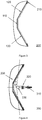
Figure 2a illustrates the position of the first critical point infigure 1 ; -
Figure 2a illustrates the position of the second critical point infigure 1 ; -
Figure 3 illustrates a schematic diagram of the window in one embodiment of the present invention; -
Figure 4 illustrates a schematic diagram of the laser line projector in one embodiment of the present invention. - The advantages of the present invention will be detailed and described in reference to the drawings and the embodiments as follows:
Figure 1 illustrates a schematic diagram of the window module in one embodiment of present invention. The window module comprises a front window, a left window, and a right window on the same plane. In order to describe the relative relationship between these three windows, the present invention will be described based on the projections of the three windows on the same plane. - As shown in
figure 1 , the projection of front window on the plane is line segment AB, the projection of left window on the plane is line segment BC, and the projection of right window on the plane is line segment AD. These three line segments create an isosceles trapezoid ABCD, wherein line segment AB is the upper bottom of the isosceles trapezoid, the line segments BC and AD are the waist of the isosceles trapezoid, and the line segment CD is the lower bottom of isosceles trapezoid (as shown on dotted line). - A Cartesian coordinate system XoY is created as follows:
- the midpoint O of line segment AB is the origin of the Cartesian coordinate system;
- the direction of line segment OB acts in the positive direction of the Y-axis;
- the direction that the perpendicular bisector of line segment AB extends towards line segment CD acts in the positive direction of the X-axis.
- In the Cartesian coordinate system XoY, the coordinates of C point are (m, n), the coordinates of D point are (m, -n), E point is the projection of B point on the line segment CD whose coordinates are (m, e), the coordinates of B point are (0, e), the coordinates of A point are (0, -e). P point is the light source point whose coordinates are (p, 0), wherein m, n, e, p satisfy the conditions as follows:

- The coordinate system is further defined that ∠CBE is a and ∠PBE is b, which both are acute angles. In order to implement the effect of eliminating stray light, a and b satisfy the conditions as follows:

- Considering O point is stationary and P point, as the light source point, is stationary as well in the Cartesian coordinate system XoY, C point and D point can be considered as the edge of the window, which are stationary as well. This means that the position of A point and B point will affect the layout of the whole window module. In other words, the value of e will affect the value of a directly and eliminate any stray lights that are caused by the window module.
- In order to obtain the value range of a, two critical points can be archived according to above description.
- The first critical point is shown in
figure 2a . The first critical point satisfies that a plus b is 90(a+b=90). And triangle CBE is similar to triangle PBO (ΔCBE ∼ ΔPBO). Therefore it can be understood that the proportion between OB and BE is equal to the proportion between OP and EC(OB/BE=OP/EC), i.e.

- Another equation as follows can be obtained after recursing the equation.

- The second critical point is shown in
figure 2b . The second critical point satisfies that a is equal to b(a=b). And triangle CBE is similar to triangle BPO (ΔCBE ∼ ΔBPO). Therefore it can be understood that the proportion between OB and EC is equal to the proportion between OP and BE (OB/EC=OP/BE), i.e.

- Another equation as follows can be obtained after recursing the equation.

- After merging equation (1) and equation (2), an inequality (3) showing the value range of a as follows can be obtained.

- Based on above arrangement, the brightness of the horizontal laser light emitted by the laser line projector is even.
-
Figure 3 illustrates the schematic diagram of the window in one embodiment of the present invention. Thewindow 200 comprises awindow frame 210 and a window module mounted in thewindow frame 210, wherein the window module comprises afront window 110, aleft window 120, and aright window 130. -
Figure 4 illustrates the schematic diagram of the laser line projector in one embodiment of the present invention. Thelaser line projector 300 comprises a housing(not shown) and a hanging system(not shown), wherein, the hanging system comprises alaser 310, acollimation apparatus 320, and acylindrical lens 330 with a high refractive index. - A
window 200, as shown infigure 3 , is provided in the housing. The laser light emitted by thelasers 310 enter thecylindrical lens 330 after being collimated by thecollimation apparatus 320 and is diverged by thecylindrical lens 330 to form a laser light with a diffusion angle which is, approximately, more than 180°. The laser light is diverged outwardly through thewindow 200. - The hanging system is provided with another laser module in one embodiment of the present invention. These two laser modules are positioned on the same horizontal level and arranged relatively. The laser lights emitted by the two laser modules intersect to form a laser light with 360° diffusion angle.
Claims (4)
- A window module, for a laser line projector comprising a light source point, comprising a front window (110), a left window (120), and a right window (130) lying on a same plane such that, the projection of the front window (110), left window (120) and right window (130) on the plane form an isosceles trapezoid,
the projection of the front window (110) is the upper bottom of the isosceles trapezoid, and the projection of the left window (120) and right window (130) is the waist of the isosceles trapezoid,
wherein the projection of the front window (110) on the plane is line segment AB, the projection of the left window (120) on the plane is line segment BC, and the projection of the right window (130) on the plane is line segment AD;
a Cartesian coordinate system is created as follows:- the midpoint O of line segment AB is the origin of the Cartesian coordinate system;- the direction of line segment OB forms in the positive direction of the Y-axis;- the direction that the perpendicular bisector of line segment AB extends towards point C or point D forms in the positive direction of the X-axis,wherein the coordinates of point C are (m, n), the coordinates of point D are (m, -n), point E is the projection of point B on the line segment CD whose coordinates are (m, e), the coordinates of point B are (0, e), the coordinates of point A are (0, -e), point P is the light source point whose coordinates are (p, 0), wherein m, n, e, p satisfy the conditions as follows:
m>0, n>0, e>0, p>0, and 0<p<m; the coordinate system further defines that angle CBE is a and angle PBE is b, which are both acute angles, characterized in that a and b satisfy the conditions as follows:
a>b and a+b>90°, and
- A window (200),
comprising a window frame (210) and window module according to claim 1 arranged in the window frame (210). - A laser line projector (300),
comprising a housing and a hanging system, wherein the housing comprises a window (200) according to claim 2,
wherein the hanging system comprises a laser module adapted to generate the light source point, said laser module comprising a laser (310), a collimation apparatus (320), and a cylindrical lens (330) with a high refractive index,
the laser light emitted by the laser (310) enters the cylindrical lens (330) after being collimated and is diverged by the cylindrical lens (330) to form at the light source point a laser light with a diffusion angle which is, approximately, more than 180°,
the laser light is diverged outwardly through the window (200). - A laser line projector (300) according to claim 3, wherein the hanging system is provided with another laser module, the two laser modules are positioned in the same horizontal level and arranged relatively, the laser lights emitted by the two laser modules intersect to form a laser light with a 360° diffusion angle.
Applications Claiming Priority (2)
| Application Number | Priority Date | Filing Date | Title |
|---|---|---|---|
| CN201210519298.8A CN103852070B (en) | 2012-12-06 | 2012-12-06 | A kind of viewer module, a kind of form and there is the laser level of this form |
| PCT/CN2013/001323 WO2014086091A1 (en) | 2012-12-06 | 2013-11-01 | Window module, window and laser line projector having the window |
Publications (3)
| Publication Number | Publication Date |
|---|---|
| EP2930464A1 EP2930464A1 (en) | 2015-10-14 |
| EP2930464A4 EP2930464A4 (en) | 2016-07-27 |
| EP2930464B1 true EP2930464B1 (en) | 2018-06-27 |
Family
ID=50860013
Family Applications (1)
| Application Number | Title | Priority Date | Filing Date |
|---|---|---|---|
| EP13859860.2A Active EP2930464B1 (en) | 2012-12-06 | 2013-11-01 | Window module, window and laser line projector having the window |
Country Status (4)
| Country | Link |
|---|---|
| US (1) | US9791271B2 (en) |
| EP (1) | EP2930464B1 (en) |
| CN (1) | CN103852070B (en) |
| WO (1) | WO2014086091A1 (en) |
Families Citing this family (1)
| Publication number | Priority date | Publication date | Assignee | Title |
|---|---|---|---|---|
| CN108020219A (en) * | 2018-01-23 | 2018-05-11 | 常州维尔曼光电仪器有限公司 | The laser of cross projection |
Family Cites Families (25)
| Publication number | Priority date | Publication date | Assignee | Title |
|---|---|---|---|---|
| WO1990013002A1 (en) * | 1989-04-14 | 1990-11-01 | Bruce George Key | Device for defining a horizontal plane |
| US5533268A (en) * | 1994-08-08 | 1996-07-09 | Miles D. Willetts | Laser deflection apparatus for laser compass |
| US5953108A (en) * | 1997-05-28 | 1999-09-14 | Laser Alignment, Inc. | Laser beam projector power and communication system |
| DE19929436A1 (en) * | 1999-06-26 | 2001-01-11 | Hilti Ag | Beam splitter for splitting a light beam into partial beams |
| DE19941030C1 (en) * | 1999-08-28 | 2001-04-26 | Hilti Ag | Laser arrangement for a multi-beam laser straightener |
| JP3532167B2 (en) * | 2001-06-01 | 2004-05-31 | 株式会社オーディオテクニカ | Laser line light irradiation method and apparatus in laser marking device |
| JP3938340B2 (en) * | 2002-07-29 | 2007-06-27 | 株式会社オーディオテクニカ | Dust-proof cover for laser marking device |
| JP2004093504A (en) * | 2002-09-03 | 2004-03-25 | Topcon Corp | Surveying equipment |
| US6938350B1 (en) * | 2002-12-31 | 2005-09-06 | PLS—Pacific Laser Systems | Apparatus for producing a reference plane |
| JP2005195936A (en) * | 2004-01-08 | 2005-07-21 | E Base:Kk | Reflective prism and light projection apparatus using the same |
| JP4328654B2 (en) * | 2004-03-23 | 2009-09-09 | 株式会社トプコン | Laser measuring method and laser measuring system |
| US7497018B2 (en) * | 2006-05-26 | 2009-03-03 | William Hersey | Laser-based alignment tool |
| US7454839B2 (en) * | 2006-08-22 | 2008-11-25 | Robotoolz, Ltd. | Portable reference laser unit and attachment accessory |
| JP4197530B2 (en) * | 2006-11-01 | 2008-12-17 | 株式会社オーディオテクニカ | Laser marking machine |
| DE202007001753U1 (en) * | 2006-12-29 | 2007-06-06 | STABILA Messgeräte Gustav Ullrich GmbH | gauge |
| CN201053615Y (en) * | 2007-04-12 | 2008-04-30 | 吴冬俊 | Traffic light |
| WO2009118937A1 (en) * | 2008-03-26 | 2009-10-01 | Hoya株式会社 | Two-dimensional scanning projector |
| CN201228908Y (en) * | 2008-06-16 | 2009-04-29 | 东莞市日盛灯饰有限公司 | Lampshade for billiard table |
| US7886450B1 (en) * | 2009-01-04 | 2011-02-15 | Joseph Fiano | Elevated laser beam positioning device |
| US8402665B2 (en) * | 2010-09-02 | 2013-03-26 | Kimokeo Inc. | Method, apparatus, and devices for projecting laser planes |
| CN202471063U (en) * | 2011-12-16 | 2012-10-03 | 西安华科光电有限公司 | Tapered trans-laser demarcation device |
| US20130167386A1 (en) * | 2011-12-28 | 2013-07-04 | Ke-Ou Peng | Optical leveling instrument with central common point consolidation structure |
| CN202485675U (en) | 2012-03-09 | 2012-10-10 | 常州华达科捷光电仪器有限公司 | Laser line-throwing instrument |
| CN202974283U (en) * | 2012-12-06 | 2013-06-05 | 常州华达科捷光电仪器有限公司 | Window module, window and laser demarcation device with window |
| JP6173067B2 (en) * | 2013-06-25 | 2017-08-02 | 株式会社トプコン | Laser surveyor |
-
2012
- 2012-12-06 CN CN201210519298.8A patent/CN103852070B/en active Active
-
2013
- 2013-11-01 EP EP13859860.2A patent/EP2930464B1/en active Active
- 2013-11-01 WO PCT/CN2013/001323 patent/WO2014086091A1/en not_active Ceased
-
2015
- 2015-06-05 US US14/732,283 patent/US9791271B2/en not_active Expired - Fee Related
Non-Patent Citations (1)
| Title |
|---|
| None * |
Also Published As
| Publication number | Publication date |
|---|---|
| EP2930464A1 (en) | 2015-10-14 |
| US20150268044A1 (en) | 2015-09-24 |
| CN103852070A (en) | 2014-06-11 |
| EP2930464A4 (en) | 2016-07-27 |
| CN103852070B (en) | 2016-08-24 |
| WO2014086091A1 (en) | 2014-06-12 |
| US9791271B2 (en) | 2017-10-17 |
Similar Documents
| Publication | Publication Date | Title |
|---|---|---|
| US10060597B2 (en) | Optical lens, backlight module and display device | |
| EP2690484B1 (en) | Head-up display device | |
| EP3076223B1 (en) | Headup display and mobile body provided with headup display | |
| US9989760B2 (en) | Headup display device | |
| JP7004849B2 (en) | Light module of automobile floodlight | |
| EP3021043B1 (en) | Lighting apparatus and automobile having lighting apparatus mounted therein | |
| TWI615659B (en) | Prism sheet and light source module using the same | |
| JP2016530688A5 (en) | ||
| EP2963478A1 (en) | Headup display device | |
| EP3379321A1 (en) | Image display device and headup display equipped with image display device | |
| KR20170063647A (en) | Head-up display device | |
| US8858056B2 (en) | Light guide plate and corresponding backlight module | |
| KR20210009312A (en) | Light guide plate, backlight module and display device | |
| US20160116832A1 (en) | Projection device capable of collecting light densely | |
| US20170269281A1 (en) | Backlight module and liquid crystal display | |
| WO2011043682A3 (en) | Method and device for coupling laser light derived from at least two laser sources into one optical fiber | |
| US20140063786A1 (en) | Backlight module and backlight lamp guide thereof | |
| US20140049830A1 (en) | Arrangement For Shaping Laser Radiation | |
| US10073209B2 (en) | Surface-light source lighting device | |
| EP3163157A1 (en) | Light guiding unit, light guiding device, and lighting and/or signal indicating device | |
| EP2930464A1 (en) | Window module, window and laser line projector having the window | |
| CN202582545U (en) | Wide-angle linear light spot laser | |
| US20210080346A1 (en) | Laser measuring system | |
| US11099429B2 (en) | Surface light source device and display device | |
| CN104423128A (en) | Projecting machine |
Legal Events
| Date | Code | Title | Description |
|---|---|---|---|
| PUAI | Public reference made under article 153(3) epc to a published international application that has entered the european phase |
Free format text: ORIGINAL CODE: 0009012 |
|
| 17P | Request for examination filed |
Effective date: 20150519 |
|
| AK | Designated contracting states |
Kind code of ref document: A1 Designated state(s): AL AT BE BG CH CY CZ DE DK EE ES FI FR GB GR HR HU IE IS IT LI LT LU LV MC MK MT NL NO PL PT RO RS SE SI SK SM TR |
|
| AX | Request for extension of the european patent |
Extension state: BA ME |
|
| DAX | Request for extension of the european patent (deleted) | ||
| RA4 | Supplementary search report drawn up and despatched (corrected) |
Effective date: 20160629 |
|
| RIC1 | Information provided on ipc code assigned before grant |
Ipc: G01C 15/00 20060101AFI20160623BHEP |
|
| GRAP | Despatch of communication of intention to grant a patent |
Free format text: ORIGINAL CODE: EPIDOSNIGR1 |
|
| STAA | Information on the status of an ep patent application or granted ep patent |
Free format text: STATUS: GRANT OF PATENT IS INTENDED |
|
| INTG | Intention to grant announced |
Effective date: 20180109 |
|
| GRAS | Grant fee paid |
Free format text: ORIGINAL CODE: EPIDOSNIGR3 |
|
| GRAA | (expected) grant |
Free format text: ORIGINAL CODE: 0009210 |
|
| STAA | Information on the status of an ep patent application or granted ep patent |
Free format text: STATUS: THE PATENT HAS BEEN GRANTED |
|
| AK | Designated contracting states |
Kind code of ref document: B1 Designated state(s): AL AT BE BG CH CY CZ DE DK EE ES FI FR GB GR HR HU IE IS IT LI LT LU LV MC MK MT NL NO PL PT RO RS SE SI SK SM TR |
|
| REG | Reference to a national code |
Ref country code: GB Ref legal event code: FG4D |
|
| REG | Reference to a national code |
Ref country code: AT Ref legal event code: REF Ref document number: 1012722 Country of ref document: AT Kind code of ref document: T Effective date: 20180715 |
|
| REG | Reference to a national code |
Ref country code: IE Ref legal event code: FG4D |
|
| REG | Reference to a national code |
Ref country code: DE Ref legal event code: R096 Ref document number: 602013039541 Country of ref document: DE |
|
| REG | Reference to a national code |
Ref country code: CH Ref legal event code: NV Representative=s name: TR-IP CONSULTING LLC, CH |
|
| REG | Reference to a national code |
Ref country code: FR Ref legal event code: PLFP Year of fee payment: 6 |
|
| PG25 | Lapsed in a contracting state [announced via postgrant information from national office to epo] |
Ref country code: SE Free format text: LAPSE BECAUSE OF FAILURE TO SUBMIT A TRANSLATION OF THE DESCRIPTION OR TO PAY THE FEE WITHIN THE PRESCRIBED TIME-LIMIT Effective date: 20180627 Ref country code: LT Free format text: LAPSE BECAUSE OF FAILURE TO SUBMIT A TRANSLATION OF THE DESCRIPTION OR TO PAY THE FEE WITHIN THE PRESCRIBED TIME-LIMIT Effective date: 20180627 Ref country code: FI Free format text: LAPSE BECAUSE OF FAILURE TO SUBMIT A TRANSLATION OF THE DESCRIPTION OR TO PAY THE FEE WITHIN THE PRESCRIBED TIME-LIMIT Effective date: 20180627 Ref country code: NO Free format text: LAPSE BECAUSE OF FAILURE TO SUBMIT A TRANSLATION OF THE DESCRIPTION OR TO PAY THE FEE WITHIN THE PRESCRIBED TIME-LIMIT Effective date: 20180927 Ref country code: BG Free format text: LAPSE BECAUSE OF FAILURE TO SUBMIT A TRANSLATION OF THE DESCRIPTION OR TO PAY THE FEE WITHIN THE PRESCRIBED TIME-LIMIT Effective date: 20180927 |
|
| REG | Reference to a national code |
Ref country code: NL Ref legal event code: MP Effective date: 20180627 |
|
| REG | Reference to a national code |
Ref country code: LT Ref legal event code: MG4D |
|
| PG25 | Lapsed in a contracting state [announced via postgrant information from national office to epo] |
Ref country code: GR Free format text: LAPSE BECAUSE OF FAILURE TO SUBMIT A TRANSLATION OF THE DESCRIPTION OR TO PAY THE FEE WITHIN THE PRESCRIBED TIME-LIMIT Effective date: 20180928 Ref country code: RS Free format text: LAPSE BECAUSE OF FAILURE TO SUBMIT A TRANSLATION OF THE DESCRIPTION OR TO PAY THE FEE WITHIN THE PRESCRIBED TIME-LIMIT Effective date: 20180627 Ref country code: LV Free format text: LAPSE BECAUSE OF FAILURE TO SUBMIT A TRANSLATION OF THE DESCRIPTION OR TO PAY THE FEE WITHIN THE PRESCRIBED TIME-LIMIT Effective date: 20180627 Ref country code: HR Free format text: LAPSE BECAUSE OF FAILURE TO SUBMIT A TRANSLATION OF THE DESCRIPTION OR TO PAY THE FEE WITHIN THE PRESCRIBED TIME-LIMIT Effective date: 20180627 |
|
| REG | Reference to a national code |
Ref country code: AT Ref legal event code: MK05 Ref document number: 1012722 Country of ref document: AT Kind code of ref document: T Effective date: 20180627 |
|
| PG25 | Lapsed in a contracting state [announced via postgrant information from national office to epo] |
Ref country code: NL Free format text: LAPSE BECAUSE OF FAILURE TO SUBMIT A TRANSLATION OF THE DESCRIPTION OR TO PAY THE FEE WITHIN THE PRESCRIBED TIME-LIMIT Effective date: 20180627 |
|
| PG25 | Lapsed in a contracting state [announced via postgrant information from national office to epo] |
Ref country code: RO Free format text: LAPSE BECAUSE OF FAILURE TO SUBMIT A TRANSLATION OF THE DESCRIPTION OR TO PAY THE FEE WITHIN THE PRESCRIBED TIME-LIMIT Effective date: 20180627 Ref country code: SK Free format text: LAPSE BECAUSE OF FAILURE TO SUBMIT A TRANSLATION OF THE DESCRIPTION OR TO PAY THE FEE WITHIN THE PRESCRIBED TIME-LIMIT Effective date: 20180627 Ref country code: AT Free format text: LAPSE BECAUSE OF FAILURE TO SUBMIT A TRANSLATION OF THE DESCRIPTION OR TO PAY THE FEE WITHIN THE PRESCRIBED TIME-LIMIT Effective date: 20180627 Ref country code: PL Free format text: LAPSE BECAUSE OF FAILURE TO SUBMIT A TRANSLATION OF THE DESCRIPTION OR TO PAY THE FEE WITHIN THE PRESCRIBED TIME-LIMIT Effective date: 20180627 Ref country code: IS Free format text: LAPSE BECAUSE OF FAILURE TO SUBMIT A TRANSLATION OF THE DESCRIPTION OR TO PAY THE FEE WITHIN THE PRESCRIBED TIME-LIMIT Effective date: 20181027 Ref country code: EE Free format text: LAPSE BECAUSE OF FAILURE TO SUBMIT A TRANSLATION OF THE DESCRIPTION OR TO PAY THE FEE WITHIN THE PRESCRIBED TIME-LIMIT Effective date: 20180627 Ref country code: CZ Free format text: LAPSE BECAUSE OF FAILURE TO SUBMIT A TRANSLATION OF THE DESCRIPTION OR TO PAY THE FEE WITHIN THE PRESCRIBED TIME-LIMIT Effective date: 20180627 |
|
| PG25 | Lapsed in a contracting state [announced via postgrant information from national office to epo] |
Ref country code: IT Free format text: LAPSE BECAUSE OF FAILURE TO SUBMIT A TRANSLATION OF THE DESCRIPTION OR TO PAY THE FEE WITHIN THE PRESCRIBED TIME-LIMIT Effective date: 20180627 Ref country code: ES Free format text: LAPSE BECAUSE OF FAILURE TO SUBMIT A TRANSLATION OF THE DESCRIPTION OR TO PAY THE FEE WITHIN THE PRESCRIBED TIME-LIMIT Effective date: 20180627 Ref country code: SM Free format text: LAPSE BECAUSE OF FAILURE TO SUBMIT A TRANSLATION OF THE DESCRIPTION OR TO PAY THE FEE WITHIN THE PRESCRIBED TIME-LIMIT Effective date: 20180627 |
|
| REG | Reference to a national code |
Ref country code: DE Ref legal event code: R097 Ref document number: 602013039541 Country of ref document: DE |
|
| PLBE | No opposition filed within time limit |
Free format text: ORIGINAL CODE: 0009261 |
|
| STAA | Information on the status of an ep patent application or granted ep patent |
Free format text: STATUS: NO OPPOSITION FILED WITHIN TIME LIMIT |
|
| PG25 | Lapsed in a contracting state [announced via postgrant information from national office to epo] |
Ref country code: DK Free format text: LAPSE BECAUSE OF FAILURE TO SUBMIT A TRANSLATION OF THE DESCRIPTION OR TO PAY THE FEE WITHIN THE PRESCRIBED TIME-LIMIT Effective date: 20180627 |
|
| 26N | No opposition filed |
Effective date: 20190328 |
|
| GBPC | Gb: european patent ceased through non-payment of renewal fee |
Effective date: 20181101 |
|
| PG25 | Lapsed in a contracting state [announced via postgrant information from national office to epo] |
Ref country code: MC Free format text: LAPSE BECAUSE OF FAILURE TO SUBMIT A TRANSLATION OF THE DESCRIPTION OR TO PAY THE FEE WITHIN THE PRESCRIBED TIME-LIMIT Effective date: 20180627 Ref country code: LU Free format text: LAPSE BECAUSE OF NON-PAYMENT OF DUE FEES Effective date: 20181101 |
|
| REG | Reference to a national code |
Ref country code: BE Ref legal event code: MM Effective date: 20181130 |
|
| REG | Reference to a national code |
Ref country code: IE Ref legal event code: MM4A |
|
| PG25 | Lapsed in a contracting state [announced via postgrant information from national office to epo] |
Ref country code: SI Free format text: LAPSE BECAUSE OF FAILURE TO SUBMIT A TRANSLATION OF THE DESCRIPTION OR TO PAY THE FEE WITHIN THE PRESCRIBED TIME-LIMIT Effective date: 20180627 |
|
| PG25 | Lapsed in a contracting state [announced via postgrant information from national office to epo] |
Ref country code: IE Free format text: LAPSE BECAUSE OF NON-PAYMENT OF DUE FEES Effective date: 20181101 |
|
| PG25 | Lapsed in a contracting state [announced via postgrant information from national office to epo] |
Ref country code: AL Free format text: LAPSE BECAUSE OF FAILURE TO SUBMIT A TRANSLATION OF THE DESCRIPTION OR TO PAY THE FEE WITHIN THE PRESCRIBED TIME-LIMIT Effective date: 20180627 Ref country code: BE Free format text: LAPSE BECAUSE OF NON-PAYMENT OF DUE FEES Effective date: 20181130 |
|
| PG25 | Lapsed in a contracting state [announced via postgrant information from national office to epo] |
Ref country code: GB Free format text: LAPSE BECAUSE OF NON-PAYMENT OF DUE FEES Effective date: 20181101 |
|
| PG25 | Lapsed in a contracting state [announced via postgrant information from national office to epo] |
Ref country code: MT Free format text: LAPSE BECAUSE OF NON-PAYMENT OF DUE FEES Effective date: 20181101 |
|
| REG | Reference to a national code |
Ref country code: CH Ref legal event code: PCAR Free format text: NEW ADDRESS: ROUTE DU COUTSET 18, 1485 NUVILLY (CH) |
|
| PG25 | Lapsed in a contracting state [announced via postgrant information from national office to epo] |
Ref country code: TR Free format text: LAPSE BECAUSE OF FAILURE TO SUBMIT A TRANSLATION OF THE DESCRIPTION OR TO PAY THE FEE WITHIN THE PRESCRIBED TIME-LIMIT Effective date: 20180627 |
|
| PG25 | Lapsed in a contracting state [announced via postgrant information from national office to epo] |
Ref country code: PT Free format text: LAPSE BECAUSE OF FAILURE TO SUBMIT A TRANSLATION OF THE DESCRIPTION OR TO PAY THE FEE WITHIN THE PRESCRIBED TIME-LIMIT Effective date: 20180627 |
|
| PG25 | Lapsed in a contracting state [announced via postgrant information from national office to epo] |
Ref country code: MK Free format text: LAPSE BECAUSE OF NON-PAYMENT OF DUE FEES Effective date: 20180627 Ref country code: CY Free format text: LAPSE BECAUSE OF FAILURE TO SUBMIT A TRANSLATION OF THE DESCRIPTION OR TO PAY THE FEE WITHIN THE PRESCRIBED TIME-LIMIT Effective date: 20180627 Ref country code: HU Free format text: LAPSE BECAUSE OF FAILURE TO SUBMIT A TRANSLATION OF THE DESCRIPTION OR TO PAY THE FEE WITHIN THE PRESCRIBED TIME-LIMIT; INVALID AB INITIO Effective date: 20131101 |
|
| PGFP | Annual fee paid to national office [announced via postgrant information from national office to epo] |
Ref country code: FR Payment date: 20231006 Year of fee payment: 11 Ref country code: DE Payment date: 20231006 Year of fee payment: 11 Ref country code: CH Payment date: 20231201 Year of fee payment: 11 |
|
| REG | Reference to a national code |
Ref country code: DE Ref legal event code: R119 Ref document number: 602013039541 Country of ref document: DE |
|
| REG | Reference to a national code |
Ref country code: CH Ref legal event code: PL |
|
| REG | Reference to a national code |
Ref country code: CH Ref legal event code: PL |
|
| PG25 | Lapsed in a contracting state [announced via postgrant information from national office to epo] |
Ref country code: CH Free format text: LAPSE BECAUSE OF NON-PAYMENT OF DUE FEES Effective date: 20241130 |
|
| PG25 | Lapsed in a contracting state [announced via postgrant information from national office to epo] |
Ref country code: DE Free format text: LAPSE BECAUSE OF NON-PAYMENT OF DUE FEES Effective date: 20250603 |
|
| PG25 | Lapsed in a contracting state [announced via postgrant information from national office to epo] |
Ref country code: FR Free format text: LAPSE BECAUSE OF NON-PAYMENT OF DUE FEES Effective date: 20241130 |