EP2930452A1 - Apparatus for separating plate-shaped hbi particles - Google Patents
Apparatus for separating plate-shaped hbi particles Download PDFInfo
- Publication number
- EP2930452A1 EP2930452A1 EP13859941.0A EP13859941A EP2930452A1 EP 2930452 A1 EP2930452 A1 EP 2930452A1 EP 13859941 A EP13859941 A EP 13859941A EP 2930452 A1 EP2930452 A1 EP 2930452A1
- Authority
- EP
- European Patent Office
- Prior art keywords
- rotor
- idle
- plate
- hbi
- driving
- Prior art date
- Legal status (The legal status is an assumption and is not a legal conclusion. Google has not performed a legal analysis and makes no representation as to the accuracy of the status listed.)
- Granted
Links
Images


Classifications
-
- C—CHEMISTRY; METALLURGY
- C21—METALLURGY OF IRON
- C21B—MANUFACTURE OF IRON OR STEEL
- C21B13/00—Making spongy iron or liquid steel, by direct processes
- C21B13/0046—Making spongy iron or liquid steel, by direct processes making metallised agglomerates or iron oxide
-
- B—PERFORMING OPERATIONS; TRANSPORTING
- B30—PRESSES
- B30B—PRESSES IN GENERAL
- B30B11/00—Presses specially adapted for forming shaped articles from material in particulate or plastic state, e.g. briquetting presses, tabletting presses
- B30B11/16—Presses specially adapted for forming shaped articles from material in particulate or plastic state, e.g. briquetting presses, tabletting presses using pocketed rollers, e.g. two co-operating pocketed rollers
-
- C—CHEMISTRY; METALLURGY
- C22—METALLURGY; FERROUS OR NON-FERROUS ALLOYS; TREATMENT OF ALLOYS OR NON-FERROUS METALS
- C22B—PRODUCTION AND REFINING OF METALS; PRETREATMENT OF RAW MATERIALS
- C22B1/00—Preliminary treatment of ores or scrap
- C22B1/14—Agglomerating; Briquetting; Binding; Granulating
-
- F—MECHANICAL ENGINEERING; LIGHTING; HEATING; WEAPONS; BLASTING
- F27—FURNACES; KILNS; OVENS; RETORTS
- F27B—FURNACES, KILNS, OVENS OR RETORTS IN GENERAL; OPEN SINTERING OR LIKE APPARATUS
- F27B19/00—Combinations of different kinds of furnaces that are not all covered by any single one of main groups F27B1/00 - F27B17/00
Definitions
- the present invention relates to an apparatus for separating particles of a plate-shaped HBI.
- DRI Direct Reduction Iron
- HBI Hot Briquetted Iron
- a plate-shaped HBI In an HBI for sale, a plate-shaped HBI should be divided into a predetermined size, and when an excessive amount of chips are produced due to excessive shock on the HBI or two or more massive HBIs are bonded due to insufficient particle separation, the yield decreases and the manufacturing cost of the HBI increases due to additional processes.
- the size of an HBI for sale is 110 c 3 , with dimensions of 102 mm X 38 mm X 42 mm.
- An apparatus for separating particles of a plate-shaped HBI needs to separate all of massive HBIs connected with each other into particles, while minimizing the number of chips.
- a technique for separating HBI into particles a technique of putting a plate-shaped HBI into a drum and separating particles using shock energy that is applied when it drops from a predetermined height along a casing of the drum has been widely known.
- the present invention has been made in an effort to provide an apparatus for separating particles of a plate-shaped HBI having advantages of being able to flexibly cope with a change in work load.
- the present invention provides an apparatus for separating particles of a plate-shaped HBI which can prevent the space between rotors from being clogged with an HBI when productivity is increased.
- An exemplary embodiment of the present invention provides an apparatus for separating particles of a plate-shaped HBI that includes: a motor; a driving rotor that is coupled to and rotated with a driving shaft of the motor and has first projections around the outer surface thereof; an idle rotor that is disposed in parallel with the driving rotor, freely rotates, and has second projections around the outer side; and a control unit that adjusts a gap between the driving rotor and the idle rotor by moving the idle rotor with respect to the driving rotor, in which the gap between the driving rotor and the idle rotor is adjusted in accordance with the amount of a plate-shaped HBI sent between the idle rotor and the driving rotor.
- the apparatus may further an inverter that is connected to the motor and adjusts a rotational speed thereof, so the rotational speed of the driving rotor can be adjusted in accordance with the amount of the plate-shaped HBI sent between the driving rotor and the idle rotor.
- bearing blocks may be disposed at both ends of a rotary shaft of the idle rotor to be movable with respect to a frame side, and elastic members may be disposed between the bearing blocks and the frame side and may press the idle rotor to the driving rotor.
- a guide rod may protrude from the bearing block and extend outward through a fastener on the frame side of the apparatus, a nut may be coupled to an end of the guide rod, the elastic member may be a spring, and the spring may be fitted on the guide rod and elastically disposed between the bearing block and the frame.
- a bottom rail may be disposed in the movement direction of the bearing block on the bottom of the frame, and the bottom of the bearing block may be slidably fitted in the bottom rail.
- a support bracket may be disposed over the bearing block on the side of the frame, a top rail may be disposed in the movement direction of the bearing block on the support bracket, and the top of the bearing block may be slidably fitted in the top rail.
- the gap between two rotors is flexibly adjusted, so clogging between the rotors can be prevented. Therefore, it is possible to prevent a decrease in productivity of an HBI and reduce work load due to repairing clogged rotors.
- FIG. 1 is a perspective view of an apparatus for separating particles of a plate-shaped HBI according to an exemplary embodiment
- FIG. 2 is a schematic plane cross-sectional view of the apparatus for separating particles of a plate-shaped HBI according to the present exemplary embodiment.
- An apparatus 100 is a rotor-type particle separator that includes two rotors and separates HBIs bonded in a plate shape into HBI particles.
- the particle separation apparatus 100 includes a driving rotor 10 and an idle rotor 20 that are rotatably mounted on a frame of the apparatus and spaced in parallel with each other, a motor 32 for rotating the driving rotor 10, and a control unit 40 for adjusting a gap between the driving rotor 10 and the idle rotor 20 by moving the idle rotor 20 with respect to the driving rotor 10 in accordance with the amount of a plate-shaped HBI P put between the driving rotor 10 and the idle rotor 20.
- the driving rotor 10 has a plurality of first projections 12 around the outer surface. As the driving rotor 10 rotates, the first projections 12 apply a shock to the plate-shaped HBI P put between the driving rotor 10 and the idle rotor 20, thereby separating particles.
- a rotary shaft 14 of the driving rotor 10 axially extends and is rotatably coupled to fixing bearing blocks 16 on a frame 30. The fixing bearing blocks 16 are fixed to the frame 30, so the driving rotor 10 cannot move from the frame 30.
- the motor 32 is disposed on a side of the frame 30, and a driving shaft 34 is coupled to the rotary shaft 14 of the driving rotor 10.
- the motor 32 is connected to an inverter 36 for adjusting the rotational speed of the motor 32.
- the apparatus 100 adjusts the rotational speed of the motor 32 by controlling the motor 32 with the inverter 36 in accordance with the amount of plate-shaped HBI P put between the driving rotor 10 and the idle rotor 20. That is, when the amount of a plate-shaped HBI P put between the driving rotor 10 and the idle rotor 20 increases, the rotational speed of the motor 32 increases and the rotational speed of the driving rotor 10 coupled to the driving shaft 34 of the motor 32 increases.
- the driving rotor 10 rotates fast and a large amount of particles can be separated from the plate-shaped HBI P.
- the apparatus can minimize clogging and sticking of a plate-shaped HBI P between the driving rotor 10 and the idle rotor 20 by adjusting the rotational speed of the motor 32 in accordance with productivity of the plate-shaped HBI P, that is, the inflow amount of the HBI P.
- the idle rotor 20 is disposed in parallel at a predetermined distance from the driving rotor 10 and is freely rotatably mounted on the frame 30.
- the idle rotor 20 has a plurality of second projections 22, which apply shock to the plate-shaped HBI P around the outer surface thereof.
- a rotary shaft 24 of the idle rotor 20 is supported by bearing blocks 26 on the frame 30. The bearing blocks 26 supporting the rotary shaft 24 of the idle rotor 20 can move with respect to the frame 30, which will be described below.
- the idle rotor 20 is not connected to the motor 32, so it does not receive torque and freely rotates regardless of the driving rotor 10.
- the idle rotor 20 rotates and applies shock to the plate-shaped HBI P, when friction with the plate-shaped HBI P having moved down is generated.
- the apparatus 100 adjusts the gap between the driving rotor 10 and the idle rotor 20 by moving the idle rotor 20 with respect to the driving rotor 10 using the control unit 40.
- FIGS. 2 and 3 show the structure of the control unit.
- the bearing blocks 26 at both ends of the rotary shaft 24 of the idle rotor 20 are arranged to be movable with respect to a frame side 37, and elastic members applying an elastic force are disposed between the bearing blocks 26 and the frame side 37 and press the idle rotor 20 to the driving rotor 10.
- the elastic members may be springs 44, but it is possible to use any member that applies an elastic force rather than the spring 44.
- the idle rotor 20 is elastically moved in accordance with the inflow amount of the plate-shaped HBI P, so the gap between the driving rotor 10 and the idle rotor 20 is adjusted, so the space between the rotors can be prevented from being clogged.
- the spring 44 is disposed between the bearing blocks 26 of the idle rotor 20 and the frame 30, and pushes the bearing blocks 26 of the idle rotor 20 to the driving rotor.
- the bearing blocks 26 have a protruding guide rod 41, and the guide rod 41 extends outward through fastening members 42 on the frame side 37 of the apparatus.
- the guide rod 41 protrudes across the movement direction of the idle rotor 20, that is, the axial direction of the idle rotor 20.
- a thread is formed at the end of the guide rod 41 passing through the fastening member 42 of the frame to couple a nut 43.
- the spring 44 is fitted on the guide rod 41 and applies elastic force between the bearing block 26 and the side 37 of the frame 30. Accordingly, the spring 44 pushes the idle rotor 20 to the driving rotor 10 by pressing the bearing block 26 toward the fixed frame side 37.
- a bottom rail 45 is disposed in the movement direction of the bearing block 26 on the bottom 38 of the frame 30, so the bottom of the bearing block 26 is slidably fitted in the bottom rail 45. Accordingly, the idle rotor 20 supported by the bearing block 26 can accurately move forward/backward to/away from the driving rotor 10 without axially moving.
- a bearing bracket 46 is disposed over the bearing block 26 on the side 37 of the frame 30, and a top rail 47 is formed in the movement direction of the bearing block 26 on the support bracket 46, so the top of the bearing block 26 is slidably fitted in the top rail 47.
- a plate-shaped HBI P pressed through a briquetting machine is supplied to the apparatus 100 and sent between the driving rotor 10 and the idle rotor 20.
- the driving rotor 10 connected to the driving shaft 34 of the motor 32 rotates.
- the driving rotor 10 is rotated by torque from the motor 32 that is an external power source, and the idle rotor 20 disposed at a predetermined distance from the driving rotor 10 is rotated by friction with the plate-shaped HBI P sent between the driving rotor 10 and the idle rotor 20.
- the driving rotor 10 As the driving rotor 10, or the driving rotor 10 and the idle rotor 20, rotate, the first projections 12 and the second projections 22 of the driving rotor 10 and the idle rotor 20 apply shock to the plate-shaped HBI P, and thereby particles are separated.
- the inverter 36 adjusts the rotational speed of the motor 32 in accordance with the inflow amount of the plate-shaped HBI P.
- the processed amount of the plate-shaped HBI P passing the driving rotor 10 changes. For example, when the inflow amount of the plate-shaped HBI P increases, the rotational speed of the driving rotor 10 increases and the plate-shaped HBI P is moved faster, so the plate-shaped HBI P is prevented from clogging between the rotors.
- the idle rotor 20 is pushed back away from the fixed driving rotor 10 and the bearing blocks 26 of the idle rotor 20 move along the top rail 47 and the bottom rail 45.
- the gap between the idle rotor 20 and the driving rotor 10 increases. Accordingly, the plate-shaped HBI P is smoothly discharged through the increased gap between the driving rotor 10 and the idle rotor 20.
- the springs 44 between the bearing blocks 26 and the frame side 37 are compressed by the bearing blocks 26 and apply elastic force to the bearing blocks 26.
- the gap between the driving rotor 10 and the idle rotor 20 is flexibly adjusted, it is possible to uniformly separate particles regardless of the inflow amount of a plate-shaped HBI P. Further, even if a plate-shaped HBI is abnormally supplied to excess, the gap between the rotors is sufficiently opened and the plate-shaped HBI can be discharged quickly, so clogging between the rotors can be prevented.
Landscapes
- Engineering & Computer Science (AREA)
- Chemical & Material Sciences (AREA)
- Mechanical Engineering (AREA)
- Manufacturing & Machinery (AREA)
- Materials Engineering (AREA)
- Metallurgy (AREA)
- Organic Chemistry (AREA)
- Environmental & Geological Engineering (AREA)
- Life Sciences & Earth Sciences (AREA)
- General Life Sciences & Earth Sciences (AREA)
- Geochemistry & Mineralogy (AREA)
- Geology (AREA)
- General Engineering & Computer Science (AREA)
- Manufacture And Refinement Of Metals (AREA)
- Centrifugal Separators (AREA)
- Combined Means For Separation Of Solids (AREA)
- Crushing And Pulverization Processes (AREA)
Description
- The present invention relates to an apparatus for separating particles of a plate-shaped HBI.
- In general, DRI (Direct Reduction Iron) at 700 °C or more is pressed into HBI and briquetted through a briquetting machine. In the plate-shaped HBI, a massive HBI (Hot Briquetted Iron) has HBI particles continuously connected in a plate shape at their edges.
- In an HBI for sale, a plate-shaped HBI should be divided into a predetermined size, and when an excessive amount of chips are produced due to excessive shock on the HBI or two or more massive HBIs are bonded due to insufficient particle separation, the yield decreases and the manufacturing cost of the HBI increases due to additional processes. In general, the size of an HBI for sale is 110 c3, with dimensions of 102
mm X 38mm X 42 mm. - An apparatus for separating particles of a plate-shaped HBI needs to separate all of massive HBIs connected with each other into particles, while minimizing the number of chips. In the related art, as a technique for separating HBI into particles, a technique of putting a plate-shaped HBI into a drum and separating particles using shock energy that is applied when it drops from a predetermined height along a casing of the drum has been widely known.
- However, the largest chronic problem with this technique is that when the productivity of an HBI increases, a drum is clogged, particle separation is poor, and it takes much time to remove the HBI clogging the drum at a high temperature and clean the drum. Accordingly, in the related art, because it takes much time to repair a drum, the operation rate of HBI separation equipment decreases and work load increases.
- The above information disclosed in this Background section is only for enhancement of understanding of the background of the invention and therefore it may contain information that does not form the prior art that is already known in this country to a person of ordinary skill in the art.
- The present invention has been made in an effort to provide an apparatus for separating particles of a plate-shaped HBI having advantages of being able to flexibly cope with a change in work load.
- Further, the present invention provides an apparatus for separating particles of a plate-shaped HBI which can prevent the space between rotors from being clogged with an HBI when productivity is increased.
- An exemplary embodiment of the present invention provides an apparatus for separating particles of a plate-shaped HBI that includes: a motor; a driving rotor that is coupled to and rotated with a driving shaft of the motor and has first projections around the outer surface thereof; an idle rotor that is disposed in parallel with the driving rotor, freely rotates, and has second projections around the outer side; and a control unit that adjusts a gap between the driving rotor and the idle rotor by moving the idle rotor with respect to the driving rotor, in which the gap between the driving rotor and the idle rotor is adjusted in accordance with the amount of a plate-shaped HBI sent between the idle rotor and the driving rotor.
- The apparatus may further an inverter that is connected to the motor and adjusts a rotational speed thereof, so the rotational speed of the driving rotor can be adjusted in accordance with the amount of the plate-shaped HBI sent between the driving rotor and the idle rotor.
- In the control unit, bearing blocks may be disposed at both ends of a rotary shaft of the idle rotor to be movable with respect to a frame side, and elastic members may be disposed between the bearing blocks and the frame side and may press the idle rotor to the driving rotor.
- A guide rod may protrude from the bearing block and extend outward through a fastener on the frame side of the apparatus, a nut may be coupled to an end of the guide rod, the elastic member may be a spring, and the spring may be fitted on the guide rod and elastically disposed between the bearing block and the frame.
- A bottom rail may be disposed in the movement direction of the bearing block on the bottom of the frame, and the bottom of the bearing block may be slidably fitted in the bottom rail.
- A support bracket may be disposed over the bearing block on the side of the frame, a top rail may be disposed in the movement direction of the bearing block on the support bracket, and the top of the bearing block may be slidably fitted in the top rail.
- As described above, according to an exemplary embodiment, when too much of a plate-shaped HBI is supplied, the gap between two rotors is flexibly adjusted, so clogging between the rotors can be prevented. Therefore, it is possible to prevent a decrease in productivity of an HBI and reduce work load due to repairing clogged rotors.
- Further, it is possible to normally work regardless of the inflow amount of a plate-shaped HBI due to a change in productivity.
-
-
FIG. 1 is a perspective view of an apparatus for separating particles of a plate-shaped HBI according to an exemplary embodiment. -
FIG. 2 is a schematic plane cross-sectional view of the apparatus for separating particles of a plate-shaped HBI according to the exemplary embodiment. -
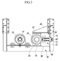
FIG. 3 is a cross-sectional view showing the configuration of a control unit in the apparatus for separating particles of a plate-shaped HBI according to the exemplary embodiment. - Hereinafter, an exemplary embodiment of the present invention will be described in detail with reference to the accompanying drawings so that those skilled in the art can easily achieve the present invention. As understood by those skilled in the art, the following exemplary embodiment may be modified in various ways without departing from the concept and scope of the present invention. Like reference numerals are used for like components in the drawings.
- The terminologies used hereafter are only for describing a specific exemplary embodiment and are not intended to limit the present invention. Singular terms used herein include plural terms unless phrases clearly express opposite meanings. The term 'including' used herein refers to concrete specific characteristics, regions, positive numbers, steps, operations, elements, and/or components, without limiting existence or addition of other specific characteristics, regions, positive numbers, steps, operations, elements, and/or components.
- All the terms, including technical terms and scientific terms used hereafter, have the same meanings as those that those skilled in the art generally understand. The terms defined in dictionaries should be construed as having meanings corresponding to the related prior art documents and those stated herein, and are not to be construed as being ideal or official, if not defined.
-
FIG. 1 is a perspective view of an apparatus for separating particles of a plate-shaped HBI according to an exemplary embodiment, andFIG. 2 is a schematic plane cross-sectional view of the apparatus for separating particles of a plate-shaped HBI according to the present exemplary embodiment. - An
apparatus 100 is a rotor-type particle separator that includes two rotors and separates HBIs bonded in a plate shape into HBI particles. - The
particle separation apparatus 100 according to the present exemplary embodiment includes adriving rotor 10 and anidle rotor 20 that are rotatably mounted on a frame of the apparatus and spaced in parallel with each other, amotor 32 for rotating thedriving rotor 10, and acontrol unit 40 for adjusting a gap between thedriving rotor 10 and theidle rotor 20 by moving theidle rotor 20 with respect to thedriving rotor 10 in accordance with the amount of a plate-shaped HBI P put between thedriving rotor 10 and theidle rotor 20. - The driving
rotor 10 has a plurality offirst projections 12 around the outer surface. As the drivingrotor 10 rotates, thefirst projections 12 apply a shock to the plate-shaped HBI P put between thedriving rotor 10 and theidle rotor 20, thereby separating particles. Arotary shaft 14 of the drivingrotor 10 axially extends and is rotatably coupled to fixingbearing blocks 16 on aframe 30. The fixingbearing blocks 16 are fixed to theframe 30, so the drivingrotor 10 cannot move from theframe 30. - The
motor 32 is disposed on a side of theframe 30, and adriving shaft 34 is coupled to therotary shaft 14 of thedriving rotor 10. In the present exemplary embodiment, themotor 32 is connected to aninverter 36 for adjusting the rotational speed of themotor 32. Theapparatus 100 adjusts the rotational speed of themotor 32 by controlling themotor 32 with theinverter 36 in accordance with the amount of plate-shaped HBI P put between thedriving rotor 10 and theidle rotor 20. That is, when the amount of a plate-shaped HBI P put between thedriving rotor 10 and theidle rotor 20 increases, the rotational speed of themotor 32 increases and the rotational speed of the drivingrotor 10 coupled to thedriving shaft 34 of themotor 32 increases. Accordingly, the drivingrotor 10 rotates fast and a large amount of particles can be separated from the plate-shaped HBI P. As described above, the apparatus can minimize clogging and sticking of a plate-shaped HBI P between thedriving rotor 10 and theidle rotor 20 by adjusting the rotational speed of themotor 32 in accordance with productivity of the plate-shaped HBI P, that is, the inflow amount of the HBI P. - The
idle rotor 20 is disposed in parallel at a predetermined distance from thedriving rotor 10 and is freely rotatably mounted on theframe 30. Theidle rotor 20 has a plurality ofsecond projections 22, which apply shock to the plate-shaped HBI P around the outer surface thereof. Arotary shaft 24 of theidle rotor 20 is supported bybearing blocks 26 on theframe 30. Thebearing blocks 26 supporting therotary shaft 24 of theidle rotor 20 can move with respect to theframe 30, which will be described below. - In the present exemplary embodiment, the
idle rotor 20 is not connected to themotor 32, so it does not receive torque and freely rotates regardless of thedriving rotor 10. Theidle rotor 20 rotates and applies shock to the plate-shaped HBI P, when friction with the plate-shaped HBI P having moved down is generated. - The
apparatus 100 adjusts the gap between thedriving rotor 10 and theidle rotor 20 by moving theidle rotor 20 with respect to thedriving rotor 10 using thecontrol unit 40. -
FIGS. 2 and3 show the structure of the control unit. In thecontrol unit 40, thebearing blocks 26 at both ends of therotary shaft 24 of theidle rotor 20 are arranged to be movable with respect to aframe side 37, and elastic members applying an elastic force are disposed between thebearing blocks 26 and theframe side 37 and press theidle rotor 20 to thedriving rotor 10. In the present exemplary embodiment, the elastic members may besprings 44, but it is possible to use any member that applies an elastic force rather than thespring 44. - Accordingly, as the
idle rotor 20 is elastically moved in accordance with the inflow amount of the plate-shaped HBI P, the gap between thedriving rotor 10 and theidle rotor 20 is adjusted, so the space between the rotors can be prevented from being clogged. - As shown in
FIG. 3 , thespring 44 is disposed between thebearing blocks 26 of theidle rotor 20 and theframe 30, and pushes thebearing blocks 26 of theidle rotor 20 to the driving rotor. - In order to install the
springs 44, thebearing blocks 26 have aprotruding guide rod 41, and theguide rod 41 extends outward through fasteningmembers 42 on theframe side 37 of the apparatus. Theguide rod 41 protrudes across the movement direction of theidle rotor 20, that is, the axial direction of theidle rotor 20. A thread is formed at the end of theguide rod 41 passing through thefastening member 42 of the frame to couple anut 43. Thespring 44 is fitted on theguide rod 41 and applies elastic force between the bearingblock 26 and theside 37 of theframe 30. Accordingly, thespring 44 pushes theidle rotor 20 to the drivingrotor 10 by pressing thebearing block 26 toward the fixedframe side 37. - It is possible to adjust the maximum movement distance of the
guide rod 41 or the force applied by thespring 44 by loosening or tightening thenut 43. - A
bottom rail 45 is disposed in the movement direction of thebearing block 26 on the bottom 38 of theframe 30, so the bottom of thebearing block 26 is slidably fitted in thebottom rail 45. Accordingly, theidle rotor 20 supported by the bearingblock 26 can accurately move forward/backward to/away from the drivingrotor 10 without axially moving. - A bearing
bracket 46 is disposed over the bearingblock 26 on theside 37 of theframe 30, and atop rail 47 is formed in the movement direction of thebearing block 26 on thesupport bracket 46, so the top of thebearing block 26 is slidably fitted in thetop rail 47. - As described above, since the top and the bottom of the
bearing block 26 of theidle rotor 20 slide on thetop rail 47 and thebottom rail 45, it can more stably and accurately move without axially moving. - Hereinafter, the operation of the apparatus is described.
- A plate-shaped HBI P pressed through a briquetting machine is supplied to the
apparatus 100 and sent between the drivingrotor 10 and theidle rotor 20. - As the
apparatus 100 is started, the drivingrotor 10 connected to the drivingshaft 34 of themotor 32 rotates. The drivingrotor 10 is rotated by torque from themotor 32 that is an external power source, and theidle rotor 20 disposed at a predetermined distance from the drivingrotor 10 is rotated by friction with the plate-shaped HBI P sent between the drivingrotor 10 and theidle rotor 20. - As the driving
rotor 10, or the drivingrotor 10 and theidle rotor 20, rotate, thefirst projections 12 and thesecond projections 22 of the drivingrotor 10 and theidle rotor 20 apply shock to the plate-shaped HBI P, and thereby particles are separated. - The
inverter 36 adjusts the rotational speed of themotor 32 in accordance with the inflow amount of the plate-shaped HBI P. As the rotational speed of the drivingrotor 10 changes in accordance with the rotational speed of themotor 32, the processed amount of the plate-shaped HBI P passing the drivingrotor 10 changes. For example, when the inflow amount of the plate-shaped HBI P increases, the rotational speed of the drivingrotor 10 increases and the plate-shaped HBI P is moved faster, so the plate-shaped HBI P is prevented from clogging between the rotors. - In this state, the
idle rotor 20 has been pressed to the driving rotor by the elastic force of thesprings 44. In this state, when the amount of the plate-shaped HBI P sent between the drivingrotor 10 and theidle rotor 20 increases, theidle rotor 20 is moved with respect to the driving rotor, so the gap between the rotors is adjusted in accordance with the inflow amount of the plate-shaped HBI P. - For example, when the inflow amount of the plate-shaped HBI P increases, a force applied to the driving
rotor 10 and theidle rotor 20 by the plate-shaped HBI P increases. Accordingly, theidle rotor 20 is pushed back away from the fixed drivingrotor 10 and the bearing blocks 26 of theidle rotor 20 move along thetop rail 47 and thebottom rail 45. As the bearing blocks 26 move, the gap between theidle rotor 20 and the drivingrotor 10 increases. Accordingly, the plate-shaped HBI P is smoothly discharged through the increased gap between the drivingrotor 10 and theidle rotor 20. Thesprings 44 between the bearing blocks 26 and theframe side 37 are compressed by the bearing blocks 26 and apply elastic force to the bearing blocks 26. When the inflow amount of the plate-shaped HBI P returns to the normal state, the force applied to theidle rotor 20 is decreased and the bearing blocks 26 are moved to the driving rotor by the elastic force of thesprings 44. Therefore, the gap between the drivingrotor 10 and theidle rotor 20 can be reduced to fit to the inflow amount of the HBI. - As described above, since the gap between the driving
rotor 10 and theidle rotor 20 is flexibly adjusted, it is possible to uniformly separate particles regardless of the inflow amount of a plate-shaped HBI P. Further, even if a plate-shaped HBI is abnormally supplied to excess, the gap between the rotors is sufficiently opened and the plate-shaped HBI can be discharged quickly, so clogging between the rotors can be prevented. - While this invention has been described in connection with what is presently considered to be practical exemplary embodiments, it is to be understood that the invention is not limited to the disclosed embodiments, but, on the contrary, is intended to cover various modifications and equivalent arrangements included within the spirit and scope of the appended claims.
Claims (6)
- An apparatus for separating particles of a plate-shaped HBI, comprising:a motor;a driving rotor that is coupled to and rotated with a driving shaft of the motor and has first projections around the outer surface thereof;an idle rotor that is disposed in parallel with the driving rotor, freely rotates, and has second projections around the outer side; anda control unit that adjusts a gap between the driving rotor and the idle rotor by moving the idle rotor with respect to the driving rotor in accordance with the amount of a plate-shaped HBI sent between the idle rotor and the driving rotor,wherein the plate-shaped HBI is divided into particles between the driving rotor and the idle rotor.
- The apparatus of claim 1, further comprising an inverter that is connected to the motor and adjusts a rotational speed thereof,
wherein the rotational speed of the driving rotor is adjusted in accordance with the amount of the plate-shaped HBI sent between the driving rotor and the idle rotor. - The apparatus of claim 1 or claim 2, wherein, in the control unit, bearing blocks are disposed at both ends of a rotary shaft of the idle rotor to be movable with respect to a frame side of the apparatus, and elastic members are disposed between the bearing blocks and the frame side and press the idle rotor to the driving rotor.
- The apparatus of claim 3, wherein a guide rod protrudes from the bearing block and extends outward through a fastener on the frame side of the apparatus, a nut is coupled to an end of the guide rod, the elastic member is a spring, and the spring is fitted on the guide rod and elastically disposed between the bearing block and the frame.
- The apparatus of claim 4, wherein a bottom rail is disposed in the movement direction of the bearing block on the bottom of the frame, and the bottom of the bearing block is slidably fitted in the bottom rail.
- The apparatus of claim 5, wherein a support bracket is disposed over the bearing block on the side of the frame, a top rail is disposed in the movement direction of the bearing block on the support bracket, and the top of the bearing block is slidably fitted in the top rail.
Applications Claiming Priority (3)
| Application Number | Priority Date | Filing Date | Title |
|---|---|---|---|
| KR20120142154 | 2012-12-07 | ||
| KR1020130083097A KR101429643B1 (en) | 2012-12-07 | 2013-07-15 | Apparatus for separating plate-shaped hbi particles |
| PCT/KR2013/007108 WO2014088184A1 (en) | 2012-12-07 | 2013-08-07 | Apparatus for separating plate-shaped hbi particles |
Publications (3)
| Publication Number | Publication Date |
|---|---|
| EP2930452A1 true EP2930452A1 (en) | 2015-10-14 |
| EP2930452A4 EP2930452A4 (en) | 2016-08-03 |
| EP2930452B1 EP2930452B1 (en) | 2018-02-28 |
Family
ID=51127461
Family Applications (1)
| Application Number | Title | Priority Date | Filing Date |
|---|---|---|---|
| EP13859941.0A Active EP2930452B1 (en) | 2012-12-07 | 2013-08-07 | Apparatus for separating plate-shaped hbi particles |
Country Status (5)
| Country | Link |
|---|---|
| EP (1) | EP2930452B1 (en) |
| KR (1) | KR101429643B1 (en) |
| CN (1) | CN104981673B (en) |
| RU (1) | RU2614498C2 (en) |
| WO (1) | WO2014088184A1 (en) |
Families Citing this family (1)
| Publication number | Priority date | Publication date | Assignee | Title |
|---|---|---|---|---|
| DE102022101419A1 (en) | 2022-01-21 | 2023-07-27 | Maschinenfabrik Köppern Gmbh & Co. Kg | Device for cutting up a strand of briquettes |
Family Cites Families (16)
| Publication number | Priority date | Publication date | Assignee | Title |
|---|---|---|---|---|
| ZA762594B (en) * | 1975-06-05 | 1977-04-27 | Midrex Corp | Method and apparatus for continuous passivation of sponge iron material |
| JPS5814938A (en) * | 1981-07-20 | 1983-01-28 | Hitachi Ltd | Granulator control method |
| DE19545985A1 (en) * | 1995-12-09 | 1997-06-12 | Metallgesellschaft Ag | Process for hot briquetting of granular sponge iron |
| US6340378B1 (en) | 1999-08-25 | 2002-01-22 | Kvaerner Metals | Method for screening hot briquetted direct reduced iron |
| JP3559555B2 (en) * | 2002-12-25 | 2004-09-02 | 産機設計有限会社 | Metal scrap lump forming equipment |
| KR101072490B1 (en) * | 2004-07-16 | 2011-10-11 | 주식회사 포스코 | An apparatus for manufacturing compacted irons of reduced materials comprising fine direct reduced irons and an apparatus for manufacturing molten irons using the same |
| KR101043078B1 (en) * | 2004-06-30 | 2011-06-21 | 주식회사 포스코 | Cheek plate pressurizing device and briquette manufacturing device using the same |
| KR101036646B1 (en) * | 2004-07-16 | 2011-05-24 | 주식회사 포스코 | Apparatus for producing compacted iron of reduced reducing iron containing reduced iron and apparatus for manufacturing molten iron using the same |
| KR101197694B1 (en) * | 2005-09-12 | 2012-11-05 | 주식회사 포스코 | Apparatus for manufacturing compacted irons comprising fine reduced irons, and apparatus for manufacturing molten irons provided with the same |
| RU2366720C2 (en) * | 2004-10-19 | 2009-09-10 | Поско | Facility for production of compacted iron out of reduced materials containing fine grain iron of direct reduction and installation for production of cast iron wherein this facility is implemented |
| DE102005006492A1 (en) * | 2005-02-12 | 2006-08-24 | S&B Industrial Minerals Gmbh | Process and apparatus for producing swellable coarse grains |
| JP5059472B2 (en) * | 2007-04-10 | 2012-10-24 | 株式会社神戸製鋼所 | Production method of carbonized metal oxide briquette |
| JP4317579B2 (en) * | 2007-09-05 | 2009-08-19 | 新日本製鐵株式会社 | Method for producing reduced iron molded body and method for producing pig iron |
| JP5092699B2 (en) * | 2007-09-12 | 2012-12-05 | 新東工業株式会社 | Briquetting sheet cutting device |
| KR101185362B1 (en) * | 2010-03-30 | 2012-09-21 | 현대제철 주식회사 | A production method of briquette using waste materials of steel making |
| KR101191964B1 (en) * | 2010-12-22 | 2012-10-18 | 주식회사 포스코 | Apparatus for producing carbon composite metal oxide briquette |
-
2013
- 2013-07-15 KR KR1020130083097A patent/KR101429643B1/en active Active
- 2013-08-07 CN CN201380063023.0A patent/CN104981673B/en active Active
- 2013-08-07 WO PCT/KR2013/007108 patent/WO2014088184A1/en not_active Ceased
- 2013-08-07 RU RU2015123796A patent/RU2614498C2/en active
- 2013-08-07 EP EP13859941.0A patent/EP2930452B1/en active Active
Also Published As
| Publication number | Publication date |
|---|---|
| EP2930452B1 (en) | 2018-02-28 |
| RU2614498C2 (en) | 2017-03-28 |
| RU2015123796A (en) | 2017-01-10 |
| WO2014088184A1 (en) | 2014-06-12 |
| CN104981673A (en) | 2015-10-14 |
| CN104981673B (en) | 2017-03-08 |
| EP2930452A4 (en) | 2016-08-03 |
| KR20140074169A (en) | 2014-06-17 |
| KR101429643B1 (en) | 2014-08-13 |
Similar Documents
| Publication | Publication Date | Title |
|---|---|---|
| CN102824936A (en) | Automatic compression roller gap regulation meshing type extruding and crushing machine | |
| EP2930452B1 (en) | Apparatus for separating plate-shaped hbi particles | |
| CN204074173U (en) | Stirring-type lapping device | |
| CN203636587U (en) | Upper grinding disc mechanism of steel ball grinding machine | |
| CN102528617A (en) | Idler wheel abrasive belt grinding machine | |
| CN107283247A (en) | A kind of magnetic shoe chamfering wears down device | |
| CN209425137U (en) | A kind of stone material grinding device | |
| CN214771131U (en) | Machining device for positioning, assembling and forming magnet | |
| CN210387383U (en) | Spring processing equipment material feeding unit | |
| CN206366929U (en) | A kind of chemical conversion machine and fixture assembly | |
| CN204933665U (en) | A kind of magnetic separator | |
| CN204182996U (en) | A kind of full-automatic milling and crushing machine | |
| CN210160739U (en) | Cross beam leveling assembly | |
| CN211895199U (en) | Forced feeding machine | |
| CN204711780U (en) | Heavy duty detergent timber floor burnishing device | |
| CN209078433U (en) | A kind of ceramic band grain edge polisher | |
| CN208994067U (en) | A logistics packaging device | |
| CN209813493U (en) | Book block clamping mechanism of glue binding machine | |
| CN102242273B (en) | Receiver of residual metals in smelting tailing | |
| CN215147837U (en) | Intelligent outer arc grinding machine for processing brake pad | |
| CN106144051A (en) | A kind of glue spreading apparatus for case binder | |
| CN203003666U (en) | Milling disc | |
| CN220330489U (en) | Pen point clamp and pen point assembling machine | |
| CN103657781A (en) | High-speed high-efficiency pulverization processing machine | |
| CN102837230A (en) | Positioning device for adjusting inclination angle of scissors clamp in scissors grinding machine |
Legal Events
| Date | Code | Title | Description |
|---|---|---|---|
| PUAI | Public reference made under article 153(3) epc to a published international application that has entered the european phase |
Free format text: ORIGINAL CODE: 0009012 |
|
| 17P | Request for examination filed |
Effective date: 20150619 |
|
| AK | Designated contracting states |
Kind code of ref document: A1 Designated state(s): AL AT BE BG CH CY CZ DE DK EE ES FI FR GB GR HR HU IE IS IT LI LT LU LV MC MK MT NL NO PL PT RO RS SE SI SK SM TR |
|
| AX | Request for extension of the european patent |
Extension state: BA ME |
|
| DAX | Request for extension of the european patent (deleted) | ||
| RA4 | Supplementary search report drawn up and despatched (corrected) |
Effective date: 20160705 |
|
| RIC1 | Information provided on ipc code assigned before grant |
Ipc: C22B 1/24 20060101ALN20160630BHEP Ipc: C21B 13/00 20060101ALI20160630BHEP Ipc: B30B 11/16 20060101ALN20160630BHEP Ipc: C22B 1/14 20060101ALI20160630BHEP Ipc: F27B 21/08 20060101AFI20160630BHEP |
|
| RIC1 | Information provided on ipc code assigned before grant |
Ipc: C21B 13/00 20060101ALI20170630BHEP Ipc: C22B 1/14 20060101ALI20170630BHEP Ipc: B30B 11/16 20060101ALN20170630BHEP Ipc: F27B 21/08 20060101AFI20170630BHEP Ipc: C22B 1/24 20060101ALN20170630BHEP |
|
| RIN1 | Information on inventor provided before grant (corrected) |
Inventor name: JUNG, JAE-HOON Inventor name: KIM, DO-SEUNG Inventor name: SHIN, MYUNG-CHAN |
|
| RIC1 | Information provided on ipc code assigned before grant |
Ipc: C22B 1/24 20060101ALN20170727BHEP Ipc: C21B 13/00 20060101ALI20170727BHEP Ipc: C22B 1/14 20060101ALI20170727BHEP Ipc: B30B 11/16 20060101ALN20170727BHEP Ipc: F27B 21/08 20060101AFI20170727BHEP |
|
| GRAP | Despatch of communication of intention to grant a patent |
Free format text: ORIGINAL CODE: EPIDOSNIGR1 |
|
| INTG | Intention to grant announced |
Effective date: 20170907 |
|
| GRAS | Grant fee paid |
Free format text: ORIGINAL CODE: EPIDOSNIGR3 |
|
| GRAA | (expected) grant |
Free format text: ORIGINAL CODE: 0009210 |
|
| AK | Designated contracting states |
Kind code of ref document: B1 Designated state(s): AL AT BE BG CH CY CZ DE DK EE ES FI FR GB GR HR HU IE IS IT LI LT LU LV MC MK MT NL NO PL PT RO RS SE SI SK SM TR |
|
| REG | Reference to a national code |
Ref country code: GB Ref legal event code: FG4D Ref country code: CH Ref legal event code: EP |
|
| REG | Reference to a national code |
Ref country code: AT Ref legal event code: REF Ref document number: 974601 Country of ref document: AT Kind code of ref document: T Effective date: 20180315 |
|
| REG | Reference to a national code |
Ref country code: IE Ref legal event code: FG4D |
|
| REG | Reference to a national code |
Ref country code: DE Ref legal event code: R096 Ref document number: 602013033860 Country of ref document: DE |
|
| REG | Reference to a national code |
Ref country code: NL Ref legal event code: MP Effective date: 20180228 |
|
| REG | Reference to a national code |
Ref country code: LT Ref legal event code: MG4D |
|
| REG | Reference to a national code |
Ref country code: AT Ref legal event code: MK05 Ref document number: 974601 Country of ref document: AT Kind code of ref document: T Effective date: 20180228 |
|
| PG25 | Lapsed in a contracting state [announced via postgrant information from national office to epo] |
Ref country code: NO Free format text: LAPSE BECAUSE OF FAILURE TO SUBMIT A TRANSLATION OF THE DESCRIPTION OR TO PAY THE FEE WITHIN THE PRESCRIBED TIME-LIMIT Effective date: 20180528 Ref country code: FI Free format text: LAPSE BECAUSE OF FAILURE TO SUBMIT A TRANSLATION OF THE DESCRIPTION OR TO PAY THE FEE WITHIN THE PRESCRIBED TIME-LIMIT Effective date: 20180228 Ref country code: NL Free format text: LAPSE BECAUSE OF FAILURE TO SUBMIT A TRANSLATION OF THE DESCRIPTION OR TO PAY THE FEE WITHIN THE PRESCRIBED TIME-LIMIT Effective date: 20180228 Ref country code: HR Free format text: LAPSE BECAUSE OF FAILURE TO SUBMIT A TRANSLATION OF THE DESCRIPTION OR TO PAY THE FEE WITHIN THE PRESCRIBED TIME-LIMIT Effective date: 20180228 Ref country code: ES Free format text: LAPSE BECAUSE OF FAILURE TO SUBMIT A TRANSLATION OF THE DESCRIPTION OR TO PAY THE FEE WITHIN THE PRESCRIBED TIME-LIMIT Effective date: 20180228 Ref country code: LT Free format text: LAPSE BECAUSE OF FAILURE TO SUBMIT A TRANSLATION OF THE DESCRIPTION OR TO PAY THE FEE WITHIN THE PRESCRIBED TIME-LIMIT Effective date: 20180228 Ref country code: CY Free format text: LAPSE BECAUSE OF FAILURE TO SUBMIT A TRANSLATION OF THE DESCRIPTION OR TO PAY THE FEE WITHIN THE PRESCRIBED TIME-LIMIT Effective date: 20180228 |
|
| REG | Reference to a national code |
Ref country code: FR Ref legal event code: PLFP Year of fee payment: 6 |
|
| PG25 | Lapsed in a contracting state [announced via postgrant information from national office to epo] |
Ref country code: BG Free format text: LAPSE BECAUSE OF FAILURE TO SUBMIT A TRANSLATION OF THE DESCRIPTION OR TO PAY THE FEE WITHIN THE PRESCRIBED TIME-LIMIT Effective date: 20180528 Ref country code: GR Free format text: LAPSE BECAUSE OF FAILURE TO SUBMIT A TRANSLATION OF THE DESCRIPTION OR TO PAY THE FEE WITHIN THE PRESCRIBED TIME-LIMIT Effective date: 20180529 Ref country code: RS Free format text: LAPSE BECAUSE OF FAILURE TO SUBMIT A TRANSLATION OF THE DESCRIPTION OR TO PAY THE FEE WITHIN THE PRESCRIBED TIME-LIMIT Effective date: 20180228 Ref country code: SE Free format text: LAPSE BECAUSE OF FAILURE TO SUBMIT A TRANSLATION OF THE DESCRIPTION OR TO PAY THE FEE WITHIN THE PRESCRIBED TIME-LIMIT Effective date: 20180228 Ref country code: LV Free format text: LAPSE BECAUSE OF FAILURE TO SUBMIT A TRANSLATION OF THE DESCRIPTION OR TO PAY THE FEE WITHIN THE PRESCRIBED TIME-LIMIT Effective date: 20180228 Ref country code: AT Free format text: LAPSE BECAUSE OF FAILURE TO SUBMIT A TRANSLATION OF THE DESCRIPTION OR TO PAY THE FEE WITHIN THE PRESCRIBED TIME-LIMIT Effective date: 20180228 |
|
| PG25 | Lapsed in a contracting state [announced via postgrant information from national office to epo] |
Ref country code: EE Free format text: LAPSE BECAUSE OF FAILURE TO SUBMIT A TRANSLATION OF THE DESCRIPTION OR TO PAY THE FEE WITHIN THE PRESCRIBED TIME-LIMIT Effective date: 20180228 Ref country code: IT Free format text: LAPSE BECAUSE OF FAILURE TO SUBMIT A TRANSLATION OF THE DESCRIPTION OR TO PAY THE FEE WITHIN THE PRESCRIBED TIME-LIMIT Effective date: 20180228 Ref country code: RO Free format text: LAPSE BECAUSE OF FAILURE TO SUBMIT A TRANSLATION OF THE DESCRIPTION OR TO PAY THE FEE WITHIN THE PRESCRIBED TIME-LIMIT Effective date: 20180228 Ref country code: AL Free format text: LAPSE BECAUSE OF FAILURE TO SUBMIT A TRANSLATION OF THE DESCRIPTION OR TO PAY THE FEE WITHIN THE PRESCRIBED TIME-LIMIT Effective date: 20180228 Ref country code: PL Free format text: LAPSE BECAUSE OF FAILURE TO SUBMIT A TRANSLATION OF THE DESCRIPTION OR TO PAY THE FEE WITHIN THE PRESCRIBED TIME-LIMIT Effective date: 20180228 |
|
| REG | Reference to a national code |
Ref country code: DE Ref legal event code: R097 Ref document number: 602013033860 Country of ref document: DE |
|
| PG25 | Lapsed in a contracting state [announced via postgrant information from national office to epo] |
Ref country code: CZ Free format text: LAPSE BECAUSE OF FAILURE TO SUBMIT A TRANSLATION OF THE DESCRIPTION OR TO PAY THE FEE WITHIN THE PRESCRIBED TIME-LIMIT Effective date: 20180228 Ref country code: SK Free format text: LAPSE BECAUSE OF FAILURE TO SUBMIT A TRANSLATION OF THE DESCRIPTION OR TO PAY THE FEE WITHIN THE PRESCRIBED TIME-LIMIT Effective date: 20180228 Ref country code: DK Free format text: LAPSE BECAUSE OF FAILURE TO SUBMIT A TRANSLATION OF THE DESCRIPTION OR TO PAY THE FEE WITHIN THE PRESCRIBED TIME-LIMIT Effective date: 20180228 Ref country code: SM Free format text: LAPSE BECAUSE OF FAILURE TO SUBMIT A TRANSLATION OF THE DESCRIPTION OR TO PAY THE FEE WITHIN THE PRESCRIBED TIME-LIMIT Effective date: 20180228 |
|
| PLBE | No opposition filed within time limit |
Free format text: ORIGINAL CODE: 0009261 |
|
| STAA | Information on the status of an ep patent application or granted ep patent |
Free format text: STATUS: NO OPPOSITION FILED WITHIN TIME LIMIT |
|
| 26N | No opposition filed |
Effective date: 20181129 |
|
| PG25 | Lapsed in a contracting state [announced via postgrant information from national office to epo] |
Ref country code: SI Free format text: LAPSE BECAUSE OF FAILURE TO SUBMIT A TRANSLATION OF THE DESCRIPTION OR TO PAY THE FEE WITHIN THE PRESCRIBED TIME-LIMIT Effective date: 20180228 |
|
| PG25 | Lapsed in a contracting state [announced via postgrant information from national office to epo] |
Ref country code: MC Free format text: LAPSE BECAUSE OF FAILURE TO SUBMIT A TRANSLATION OF THE DESCRIPTION OR TO PAY THE FEE WITHIN THE PRESCRIBED TIME-LIMIT Effective date: 20180228 |
|
| REG | Reference to a national code |
Ref country code: CH Ref legal event code: PL |
|
| GBPC | Gb: european patent ceased through non-payment of renewal fee |
Effective date: 20180807 |
|
| PG25 | Lapsed in a contracting state [announced via postgrant information from national office to epo] |
Ref country code: LI Free format text: LAPSE BECAUSE OF NON-PAYMENT OF DUE FEES Effective date: 20180831 Ref country code: LU Free format text: LAPSE BECAUSE OF NON-PAYMENT OF DUE FEES Effective date: 20180807 Ref country code: CH Free format text: LAPSE BECAUSE OF NON-PAYMENT OF DUE FEES Effective date: 20180831 |
|
| REG | Reference to a national code |
Ref country code: BE Ref legal event code: MM Effective date: 20180831 |
|
| REG | Reference to a national code |
Ref country code: IE Ref legal event code: MM4A |
|
| PG25 | Lapsed in a contracting state [announced via postgrant information from national office to epo] |
Ref country code: IE Free format text: LAPSE BECAUSE OF NON-PAYMENT OF DUE FEES Effective date: 20180807 |
|
| PG25 | Lapsed in a contracting state [announced via postgrant information from national office to epo] |
Ref country code: BE Free format text: LAPSE BECAUSE OF NON-PAYMENT OF DUE FEES Effective date: 20180831 |
|
| PG25 | Lapsed in a contracting state [announced via postgrant information from national office to epo] |
Ref country code: GB Free format text: LAPSE BECAUSE OF NON-PAYMENT OF DUE FEES Effective date: 20180807 |
|
| PG25 | Lapsed in a contracting state [announced via postgrant information from national office to epo] |
Ref country code: MT Free format text: LAPSE BECAUSE OF NON-PAYMENT OF DUE FEES Effective date: 20180807 |
|
| PG25 | Lapsed in a contracting state [announced via postgrant information from national office to epo] |
Ref country code: TR Free format text: LAPSE BECAUSE OF FAILURE TO SUBMIT A TRANSLATION OF THE DESCRIPTION OR TO PAY THE FEE WITHIN THE PRESCRIBED TIME-LIMIT Effective date: 20180228 |
|
| PG25 | Lapsed in a contracting state [announced via postgrant information from national office to epo] |
Ref country code: PT Free format text: LAPSE BECAUSE OF FAILURE TO SUBMIT A TRANSLATION OF THE DESCRIPTION OR TO PAY THE FEE WITHIN THE PRESCRIBED TIME-LIMIT Effective date: 20180228 |
|
| PG25 | Lapsed in a contracting state [announced via postgrant information from national office to epo] |
Ref country code: MK Free format text: LAPSE BECAUSE OF NON-PAYMENT OF DUE FEES Effective date: 20180228 Ref country code: HU Free format text: LAPSE BECAUSE OF FAILURE TO SUBMIT A TRANSLATION OF THE DESCRIPTION OR TO PAY THE FEE WITHIN THE PRESCRIBED TIME-LIMIT; INVALID AB INITIO Effective date: 20130807 |
|
| PG25 | Lapsed in a contracting state [announced via postgrant information from national office to epo] |
Ref country code: IS Free format text: LAPSE BECAUSE OF FAILURE TO SUBMIT A TRANSLATION OF THE DESCRIPTION OR TO PAY THE FEE WITHIN THE PRESCRIBED TIME-LIMIT Effective date: 20180628 |
|
| REG | Reference to a national code |
Ref country code: DE Ref legal event code: R081 Ref document number: 602013033860 Country of ref document: DE Owner name: POSCO CO., LTD, POHANG-SI, KR Free format text: FORMER OWNER: POSCO, POHANG-SI, GYEONGSANGBUK-DO, KR Ref country code: DE Ref legal event code: R081 Ref document number: 602013033860 Country of ref document: DE Owner name: POSCO CO., LTD, POHANG- SI, KR Free format text: FORMER OWNER: POSCO, POHANG-SI, GYEONGSANGBUK-DO, KR Ref country code: DE Ref legal event code: R081 Ref document number: 602013033860 Country of ref document: DE Owner name: POSCO HOLDINGS INC., KR Free format text: FORMER OWNER: POSCO, POHANG-SI, GYEONGSANGBUK-DO, KR |
|
| REG | Reference to a national code |
Ref country code: DE Ref legal event code: R081 Ref document number: 602013033860 Country of ref document: DE Owner name: POSCO CO., LTD, POHANG-SI, KR Free format text: FORMER OWNER: POSCO HOLDINGS INC., SEOUL, KR Ref country code: DE Ref legal event code: R081 Ref document number: 602013033860 Country of ref document: DE Owner name: POSCO CO., LTD, POHANG- SI, KR Free format text: FORMER OWNER: POSCO HOLDINGS INC., SEOUL, KR |
|
| PGFP | Annual fee paid to national office [announced via postgrant information from national office to epo] |
Ref country code: FR Payment date: 20250624 Year of fee payment: 13 |
|
| PGFP | Annual fee paid to national office [announced via postgrant information from national office to epo] |
Ref country code: DE Payment date: 20250624 Year of fee payment: 13 |