EP2930394A1 - Vehicle height adjustment device - Google Patents
Vehicle height adjustment device Download PDFInfo
- Publication number
- EP2930394A1 EP2930394A1 EP13860127.3A EP13860127A EP2930394A1 EP 2930394 A1 EP2930394 A1 EP 2930394A1 EP 13860127 A EP13860127 A EP 13860127A EP 2930394 A1 EP2930394 A1 EP 2930394A1
- Authority
- EP
- European Patent Office
- Prior art keywords
- spring
- spring receiver
- movable spring
- guide surface
- housing
- Prior art date
- Legal status (The legal status is an assumption and is not a legal conclusion. Google has not performed a legal analysis and makes no representation as to the accuracy of the status listed.)
- Withdrawn
Links
Images



Classifications
-
- B—PERFORMING OPERATIONS; TRANSPORTING
- B60—VEHICLES IN GENERAL
- B60G—VEHICLE SUSPENSION ARRANGEMENTS
- B60G17/00—Resilient suspensions having means for adjusting the spring or vibration-damper characteristics, for regulating the distance between a supporting surface and a sprung part of vehicle or for locking suspension during use to meet varying vehicular or surface conditions, e.g. due to speed or load
- B60G17/02—Spring characteristics, e.g. mechanical springs and mechanical adjusting means
- B60G17/027—Mechanical springs regulated by fluid means
- B60G17/0272—Mechanical springs regulated by fluid means the mechanical spring being a coil spring
-
- F—MECHANICAL ENGINEERING; LIGHTING; HEATING; WEAPONS; BLASTING
- F16—ENGINEERING ELEMENTS AND UNITS; GENERAL MEASURES FOR PRODUCING AND MAINTAINING EFFECTIVE FUNCTIONING OF MACHINES OR INSTALLATIONS; THERMAL INSULATION IN GENERAL
- F16F—SPRINGS; SHOCK-ABSORBERS; MEANS FOR DAMPING VIBRATION
- F16F1/00—Springs
- F16F1/02—Springs made of steel or other material having low internal friction; Wound, torsion, leaf, cup, ring or the like springs, the material of the spring not being relevant
- F16F1/04—Wound springs
- F16F1/12—Attachments or mountings
- F16F1/121—Attachments or mountings adjustable, e.g. to modify spring characteristics
-
- F—MECHANICAL ENGINEERING; LIGHTING; HEATING; WEAPONS; BLASTING
- F16—ENGINEERING ELEMENTS AND UNITS; GENERAL MEASURES FOR PRODUCING AND MAINTAINING EFFECTIVE FUNCTIONING OF MACHINES OR INSTALLATIONS; THERMAL INSULATION IN GENERAL
- F16F—SPRINGS; SHOCK-ABSORBERS; MEANS FOR DAMPING VIBRATION
- F16F9/00—Springs, vibration-dampers, shock-absorbers, or similarly-constructed movement-dampers using a fluid or the equivalent as damping medium
- F16F9/32—Details
- F16F9/38—Covers for protection or appearance
-
- F—MECHANICAL ENGINEERING; LIGHTING; HEATING; WEAPONS; BLASTING
- F16—ENGINEERING ELEMENTS AND UNITS; GENERAL MEASURES FOR PRODUCING AND MAINTAINING EFFECTIVE FUNCTIONING OF MACHINES OR INSTALLATIONS; THERMAL INSULATION IN GENERAL
- F16F—SPRINGS; SHOCK-ABSORBERS; MEANS FOR DAMPING VIBRATION
- F16F9/00—Springs, vibration-dampers, shock-absorbers, or similarly-constructed movement-dampers using a fluid or the equivalent as damping medium
- F16F9/32—Details
- F16F9/56—Means for adjusting the length of, or for locking, the spring or damper, e.g. at the end of the stroke
-
- B—PERFORMING OPERATIONS; TRANSPORTING
- B60—VEHICLES IN GENERAL
- B60G—VEHICLE SUSPENSION ARRANGEMENTS
- B60G17/00—Resilient suspensions having means for adjusting the spring or vibration-damper characteristics, for regulating the distance between a supporting surface and a sprung part of vehicle or for locking suspension during use to meet varying vehicular or surface conditions, e.g. due to speed or load
- B60G17/02—Spring characteristics, e.g. mechanical springs and mechanical adjusting means
- B60G17/04—Spring characteristics, e.g. mechanical springs and mechanical adjusting means fluid spring characteristics
- B60G17/052—Pneumatic spring characteristics
- B60G17/0523—Regulating distributors or valves for pneumatic springs
- B60G17/0525—Height adjusting or levelling valves
-
- B—PERFORMING OPERATIONS; TRANSPORTING
- B60—VEHICLES IN GENERAL
- B60G—VEHICLE SUSPENSION ARRANGEMENTS
- B60G2202/00—Indexing codes relating to the type of spring, damper or actuator
- B60G2202/30—Spring/Damper and/or actuator Units
- B60G2202/31—Spring/Damper and/or actuator Units with the spring arranged around the damper, e.g. MacPherson strut
-
- B—PERFORMING OPERATIONS; TRANSPORTING
- B60—VEHICLES IN GENERAL
- B60G—VEHICLE SUSPENSION ARRANGEMENTS
- B60G2202/00—Indexing codes relating to the type of spring, damper or actuator
- B60G2202/30—Spring/Damper and/or actuator Units
- B60G2202/31—Spring/Damper and/or actuator Units with the spring arranged around the damper, e.g. MacPherson strut
- B60G2202/312—The spring being a wound spring
-
- B—PERFORMING OPERATIONS; TRANSPORTING
- B60—VEHICLES IN GENERAL
- B60G—VEHICLE SUSPENSION ARRANGEMENTS
- B60G2202/00—Indexing codes relating to the type of spring, damper or actuator
- B60G2202/30—Spring/Damper and/or actuator Units
- B60G2202/32—The spring being in series with the damper and/or actuator
-
- B—PERFORMING OPERATIONS; TRANSPORTING
- B60—VEHICLES IN GENERAL
- B60G—VEHICLE SUSPENSION ARRANGEMENTS
- B60G2202/00—Indexing codes relating to the type of spring, damper or actuator
- B60G2202/40—Type of actuator
- B60G2202/41—Fluid actuator
- B60G2202/413—Hydraulic actuator
-
- B—PERFORMING OPERATIONS; TRANSPORTING
- B60—VEHICLES IN GENERAL
- B60G—VEHICLE SUSPENSION ARRANGEMENTS
- B60G2300/00—Indexing codes relating to the type of vehicle
- B60G2300/12—Cycles; Motorcycles
-
- B—PERFORMING OPERATIONS; TRANSPORTING
- B60—VEHICLES IN GENERAL
- B60G—VEHICLE SUSPENSION ARRANGEMENTS
- B60G2500/00—Indexing codes relating to the regulated action or device
- B60G2500/30—Height or ground clearance
- B60G2500/32—Height or ground clearance of only one vehicle part or side
- B60G2500/324—Height or ground clearance of only one vehicle part or side only rear part
Definitions
- the present invention relates to a vehicle height adjusting apparatus.
- a damper for generating a damping force and a suspension spring for biasing the damper in an expansion direction are provided in parallel.
- the suspension spring absorbs an impact caused by irregularity on a road surface, and the damper suppresses an expansion/contraction motion of the suspension spring associated with impact absorption. As a result, transmission of the impact caused by the irregularity on the road surface to the vehicle body is suppressed.
- JP2010-149550A discloses a vehicle height adjusting apparatus.
- the vehicle height adjusting apparatus includes: a movable spring receiver 8 for supporting one -side end (an upper end in FIG. 4 ) of a suspension spring S1 that is mounted on an outer periphery of an outer tube T of a damper D and biases the damper D in an expansion direction; and a driving mechanism M for driving the movable spring receiver 8 in an axial direction of the damper D.
- the driving mechanism M includes: an annular housing 90 fixed to a side opposite to the suspension spring (an upper side in FIG. 4 ) of the movable spring receiver 8 on the outer periphery of the outer tube T; a jack chamber J formed between the housing 90 and the outer tube T and filled with an operating fluid; a jack piston 91 continuing to the side opposite to the suspension spring of the movable spring receiver 8 (the upper side in FIG. 4 ) and movably inserted between the housing 90 and the outer tube T so as to close an opening on the suspension spring side of the jack chamber J (a lower side in FIG. 4 ); and a pump P configured to suction and discharge the operating fluid with respect to the jack chamber J.
- JP11-182609A discloses a suspension spring force adjusting apparatus.
- the suspension spring force adjusting apparatus includes a dust cover 2C that suppresses adhesion of dusts by covering a portion where the movable spring receiver 8 and the jack piston 91 are in sliding contact.
- the movable spring receiver 8 is sandwiched by the suspension spring S1 and an auxiliary spring so as to be biased by the auxiliary spring to the suspension spring side, that is, in a direction in which the suspension spring S1 contracts.
- a vehicle height adjusting apparatus includes: an annular movable spring receiver in sliding contact with a guide surface formed on an outer periphery of an outer tube of a damper, the movable spring receiver being configured to support one side end of a suspension spring, the suspension spring biasing the damper in an expansion direction; a driving mechanism configured to drive the movable spring receiver in an axial direction of the damper; an auxiliary spring configured to bias the movable spring receiver to the suspension spring side; and a dust cover configured to cover a portion on the guide surface, the movable spring receiver being in sliding contact with the guide surface in the portion, wherein the dust cover is held on the outer tube by means of a spring force of the auxiliary spring.
- FIG. 1 is a front view showing a damper D partially cut out, on which a vehicle height adjusting apparatus 100 according to the present embodiment is mounted.
- the same reference numerals given through several drawings denote the same or corresponding components, respectively.
- the vehicle height adjusting apparatus 100 includes: an annular movable spring receiver 1 in sliding contact with a guide surface 30 formed on an outer periphery of an outer tube T of the damper D, the annular movable spring receiver 1 being configured to support one side end (an upper end in FIG. 1 ) of a suspension spring S1 biasing the damper D in an expansion direction; a driving mechanism M configured to drive the movable spring receiver 1 in an axial direction of the damper D; an auxiliary spring S2 configured to bias the movable spring receiver 1 to a suspension spring side; and a dust cover 2A configured to cover a portion on the guide surface 30 with which the movable spring receiver 1 is in sliding contact.
- the dust cover 2A is held on the outer tube T by means of a spring force of the auxiliary spring S2.
- the damper D is an inverted damper that includes: the outer tube T connected to a vehicle body side via a vehicle body side bracket B1; and a piston rod R connected to a wheel side via a wheel side bracket B2.
- the piston rod R is movably inserted into the outer tube T in the axial direction, and the damper D is expanded and contracted by the piston rod R going into/out of the outer tube T.
- the damper D generates a predetermined damping force with expansion/contraction thereof to suppress an expansion/contraction motion of the suspension spring S1. Since any configuration may be adopted as a configuration in which the damper D generates the damping force, detailed explanation of the configuration is omitted. Further, the damper D may be an upright damper in which a piston rod R is connected to a vehicle body side and an outer tube T is connected to a wheel side.
- the movable spring receiver 1 and a jack piston 7 which will be described later are in sliding contact with the guide surface 30 and can be smoothly moved along the guide tube 3.
- a support member 4 projecting outward from the outer tube T is fixed on a vehicle body side end of the outer tube T (the upper end in FIG. 1 ). It is only necessary that the support member 4 is connected to the outer tube T so as not to move, and as a method of connecting the support member 4 to the outer tube T, an appropriate known method such as integral forming, screwing, fitting and the like may be adopted.
- the suspension spring S1 made of a coil spring is mounted on an outer periphery of the damper D.
- the suspension spring S1 is interposed between the movable spring receiver 1 connected to the vehicle body side and a fixed spring receiver 5 connected to the wheel side to bias the movable spring receiver 1 and the fixed spring receiver 5 in a direction to be separated from each other.
- the suspension spring S1 biases the damper D in the expansion direction in which the piston rod R goes out of the outer tube T.
- the movable spring receiver 1 is formed in an annular manner and in sliding contact with the guide surface 30 of the guide tube 3.
- the movable spring receiver 1 is movable in the axial direction of the damper D, and constitutes the vehicle height adjusting apparatus 100 for adjusting the vehicle height.
- the fixed spring receiver 5 is formed in an annular manner.
- the fixed spring receiver 5 is supported by the wheel side bracket B2, and is pressed onto the wheel side bracket B2 by means of the suspension spring S 1 so that movement thereof in the axial direction is regulated.
- the vehicle height adjusting apparatus 100 includes: the movable spring receiver 1; the driving mechanism M configured to drive the movable spring receiver 1 in the axial direction of the damper D; the auxiliary spring S2 configured to bias the movable spring receiver 1 to the suspension spring side; and the dust cover 2A configured to cover the portion in the guide surface 30 with which the movable spring receiver 1 is in sliding contact.
- the movable spring receiver 1 constituting the vehicle height adjusting apparatus 100 includes: an annular support portion 10 configured to support a vehicle body side end (one side end) of the suspension spring S1; and a cylindrical guide portion 11 configured to stand substantially perpendicularly from an inner peripheral edge of a suspension spring side surface (a lower surface in FIG. 2 ) of the support portion 10.
- the guide portion 11 supports an inner periphery of the vehicle body side end portion (one side end portion) of the suspension spring S1.
- a thickness of an inner periphery portion 10a in the support portion 10 is formed so as to be larger than a thickness of an outer periphery portion 10b. As a result, the inner periphery portion 10a protrudes to the side opposite to the suspension spring (an upper side in FIG. 2 ) compared with the outer periphery portion 10b.
- the driving mechanism M constituting the vehicle height adjusting apparatus 100 and driving the movable spring receiver 1 includes: a housing 6 fixed to the outer periphery of the outer tube T and on the side opposite to the suspension spring of the movable spring receiver 1 (upper sides in FIGS. 1 and 2 ); a jack chamber J formed between the housing 6 and the guide surface 30 and filled with an operating fluid; a jack piston 7 brought into contact with the side opposite to the suspension spring of the movable spring receiver 1 (upper sides in FIGS. 1 and 2 ) and configured to be inserted movably between the housing 6 and the guide surface 30 to close an opening on the suspension spring side of the jack chamber J (lower sides in FIGS. 1 and 2 ); and the pump P ( FIG. 1 ) configured to suction and discharge the operating fluid with respect to the jack chamber J.
- the housing 6 constituting the driving mechanism M is formed into a bottomed cylindrical shape as shown in FIG. 2 .
- the housing 6 includes an annular bottom portion 60 and a cylindrical portion 61 having a cylindrical shape.
- the cylindrical portion 61 stands substantially perpendicularly from the suspension spring side surface (the lower surface in FIG. 2 ) of the bottom portion 60.
- the housing 6 is arranged so as to cause the bottom portion 60 to face the vehicle body side (the upper side in FIG. 2 ) and to cause the cylindrical portion 61 to face the suspension spring side (a lower side in FIG. 2 ).
- the housing 6 is pressed onto the support member 4 by the suspension spring S1, and is fixed in a locked state. Namely, the housing 6 is fixed to the outer tube T via the support member 4.
- the cylindrical portion 61 of the housing 6 is arranged so that a predetermined gap is formed between the cylindrical portion 61 and an outer periphery of the guide surface 30 of the guide tube 3. In this gap, a non-compressive operating fluid is stored, and the annular jack chamber J is formed.
- An inner periphery portion 60a of the bottom portion 60 in the housing 6 protrudes inward from the cylindrical portion 61, and an annular seal 62 is mounted on an inner periphery of the inner periphery portion 60a.
- the seal 62 is in close contact with the guide surface 30 of the guide tube 3.
- the inner periphery portion 60a of the bottom portion 60 closes an opening on the side opposite to the suspension spring (the upper side in FIG. 2 ) of the jack chamber J in a liquid-tight manner, and prevents the operating fluid in the jack chamber J from flowing out of a gap between the bottom portion 60 of the housing 6 and the guide tube 3.
- An outer periphery portion 60b of the bottom portion 60 of the housing 6 projects outward from the cylindrical portion 61.
- the jack piston 7 constituting the driving mechanism M includes: an annular piston portion 70 configured to be inserted movably between the cylindrical portion 61 of the housing 6 and the guide surface 30 of the guide tube 3 to close an opening on the suspension spring side (the lower side in FIG. 2 ) of the jack chamber J; and an extended portion 71 continuing to the suspension spring side (the lower side in FIG. 2 ) of the piston portion 70.
- Annular seals 72 and 73 are respectively mounted on an inner periphery and an outer periphery of the piston portion 70.
- the inner peripheral side seal 72 is in sliding contact with the guide surface 30 of the guide tube 3, while the outer peripheral side seal 73 is in sliding contact with the inner peripheral surface of the cylindrical portion 61.
- the jack piston 7 is in sliding contact with the guide surface 30 of the guide tube 3 via the inner peripheral side seal 72, and is in sliding contact with the inner peripheral surface of the cylindrical portion 61 via the outer peripheral side seal 73.
- the jack piston 7 closes the opening on the suspension spring side (the lower side in FIG. 2 ) of the jack chamber J in the liquid-tight manner.
- the extended portion 71 is configured so that a suspension spring side end portion 71 a of the extended portion 71 protrudes downward compared with the cylindrical portion 61 of the housing 6 even in a case where the movable spring receiver 1 retreats the most and the jack piston 7 is at a jack minimum position where the jack piston 7 enters the housing 6 the most.
- an axial size of the jack piston 7 is set so that the suspension spring side end portion 71a of the extended portion 71 always protrudes from the housing 6.
- the pump P constituting the driving mechanism M is connected to the jack chamber J through a hose H, and is driven by a motor (not shown) to suction and discharge the operating fluid with respect to the jack chamber J. Since any constitution may be adopted as the constitution of the pump P, detailed explanation of the configuration of the pump P is omitted. Further, the pump P may be an electric pump driven by the motor, or may be a manual pump manually driven.
- the auxiliary spring S2 constituting the vehicle height adjusting apparatus 100 together with the driving mechanism M is made of a coil spring. As shown in FIG. 2 , the auxiliary spring S2 is arranged on an outer periphery of the cylindrical portion 61 of the housing 6. The auxiliary spring S2 is interposed between the outer periphery portion 10b of the support portion 10 of the movable spring receiver 1 and the outer periphery portion 60b of the bottom portion 60 of the housing 6. The auxiliary spring S2 is arranged in series with the suspension spring S1, and biases the movable spring receiver 1 to the suspension spring side (the lower side in FIG. 2 ) to compress the suspension spring S1.
- a force acting on the suspension spring S1 or the auxiliary spring S2 is referred to as a load.
- a load of the auxiliary spring S2 becomes the largest in a case where the movable spring receiver 1 retreats the most and the jack piston 7 is at the jack minimum position where the jack piston 7 enters the housing 6 the most.
- the load of the auxiliary spring S2 at this time is referred to as a maximum load at assembling of the auxiliary spring S2.
- a load of the suspension spring S1 becomes the smallest when the jack piston 7 is at the jack minimum position and the damper D is expanded the most.
- the load of the suspension spring S1 at this time is referred to as a minimum load at assembling of the suspension spring.
- the maximum load at assembling of the auxiliary spring S2 is set so as to be smaller than the minimum load at assembling of the suspension spring S1.
- the dust cover 2A constituting the vehicle height adjusting apparatus 100 includes: a seat portion 20 formed into an annular plate shape and with which the one side end of the auxiliary spring S2 (the upper end in FIG. 2 ) is brought into contact; and a cylindrical cover portion 21 standing from an outer peripheral edge of the seat portion 20.
- the dust cover 2A is arranged so as to cause the seat portion 20 to face the outer periphery portion 60b side of the bottom portion 60 of the housing 6, and arranged so that the cover portion 21 covers the movable spring receiver 1 and the auxiliary spring S2.
- the auxiliary spring S2 is compressed by the suspension spring S1 via the movable spring receiver 1. For this reason, the seat portion 20 is pressed onto the bottom portion 60 of the housing 6 by means of a spring force (restoring force, reaction force) of the auxiliary spring S2, and the seat portion 20 is sandwiched by the auxiliary spring S2 and the bottom portion 60 of the housing 6. Thus, the dust cover 2A is held on the outer tube T of the damper D by means of the spring force of the auxiliary spring S2.
- a length of the cover portion 21 of the dust cover 2A is set so that the movable spring receiver 1 does not protrude from the cover portion 21 even if the movable spring receiver 1 is moved. Namely, the cover portion 21 covers an entire portion of the guide surface 30 with which the movable spring receiver 1 is in sliding contact.
- the pump P is driven so as to supply the operating fluid to the jack chamber J, the jack piston 7 is pushed out of the housing 6.
- the outer tube T is pushed up to the upper side in FIG. 1 and the damper D is expanded, whereby the vehicle height is raised.
- the pump P is driven so as to discharge the operating fluid from the jack chamber J, the jack piston 7 is pushed into the housing 6.
- the outer tube T is moved to the lower side in FIG. 1 , and the damper D is compressed, whereby the vehicle height is lowered.
- the vehicle height adjusting apparatus 100 includes: the annular movable spring receiver 1 in sliding contact with the guide surface 30 formed on the outer periphery of the outer tube T of the damper D, the annular movable spring receiver 1 being configured to support the one side end (the upper end in FIG. 1 ) of the suspension spring S1 biasing the damper D in the expansion direction; the driving mechanism M configured to drive the movable spring receiver 1 in the axial direction of the damper D; the auxiliary spring S2 configured to bias the movable spring receiver 1 to the suspension spring side; and the dust cover 2A configured to cover the portion on the guide surface 30 with which the movable spring receiver 1 is in sliding contact.
- the dust cover 2A is held on the outer tube T by means of the spring force of the auxiliary spring S2.
- the dust cover 2A is mounted by using the spring force of the auxiliary spring S2. For this reason, mounting of the dust cover 2A can be facilitated. Further, since the vehicle height adjusting apparatus 100 is provided with the auxiliary spring S2, the movable spring receiver 1 can be driven by means of a smaller force in a case where adjustment is made in the direction in which the vehicle height is raised. Moreover, since the vehicle height adjusting apparatus 100 is provided with the dust cover 2A, it is possible to suppress dusts from adhering onto the guide surface 30 with which the movable spring receiver 1 is in sliding contact, and the movable spring receiver 1 can be smoothly moved along the guide surface 30.
- the driving mechanism M includes: the housing 6 fixed to the outer periphery of the outer tube T and on the side opposite to the suspension spring of the movable spring receiver 1 (the upper side in FIG. 1 ); the jack chamber J formed between the housing 6 and the guide surface 30 and filled with the operating fluid; the jack piston 7 brought into contact with the side opposite to the suspension spring (the upper side in FIG. 1 ) of the movable spring receiver 1, and configured to be inserted movably between the housing 6 and the guide surface 30 to close the opening on the suspension spring side (the lower side in FIG. 1 ) of the jack chamber J; and the pump P configured to suction and discharge the operating fluid with respect to the jack chamber J.
- the movable spring receiver 1 can be driven easily via the jack piston 7.
- the seals 72 and 73 for ensuring the jack chamber J in the liquid-tight manner are provided in the jack piston 7, and the jack piston 7 is in sliding contact with the guide surface 30 via the seal 72. Since the dust cover 2A covers the portion of the guide surface 30 with which the movable spring receiver 1 is in sliding contact, it is possible to suppress the seal 72 from being scratched due to the dust adhering to the guide surface 30, and this makes it possible to improve durability of the seal 72.
- the housing 6 is formed into a bottomed cylindrical shape, and includes: the annular bottom portion 60 mounted on the outer periphery of the guide surface 30 in the liquid-tight manner; and the cylindrical portion 61 standing from the suspension spring side surface (the lower surface in FIG. 2 ) of the bottom portion 60.
- the jack chamber J is defined between the cylindrical portion 61 and the guide surface 30.
- the outer periphery portion 60b of the bottom portion 60 projects outward from the cylindrical portion 61, and the auxiliary spring S2 is interposed between the outer periphery portion 60b which is the outer periphery of the cylindrical portion 61 and the movable spring receiver 1.
- the vehicle height adjusting apparatus 100 can be formed compactly.
- the dust cover 2A includes: the seat portion 20 formed into an annular plate shape and with which the one side end (the upper end in FIG. 2 ) of the auxiliary spring S2 is brought into contact; and the cylindrical cover portion 21 standing from the outer peripheral edge of the seat portion 20.
- the seat portion 20 is sandwiched by the auxiliary spring S2 and the outer periphery portion 60b of the bottom portion 60 in the housing 6, and the cover portion 21 covers the movable spring receiver 1 and the auxiliary spring S2.
- the dust cover 2A covers the movable spring receiver 1, the auxiliary spring S2, the jack piston 7, and the jack chamber J, it is possible to suppress dusts from adhering on the movable spring receiver 1, the auxiliary spring S2, the jack piston 7, and the jack chamber J.
- auxiliary spring S2 is arranged inside the dust cover 2A, a coil diameter of the auxiliary spring S2 can be made smaller compared with the case in which the auxiliary spring S2 is arranged outside the dust cover 2A, and this makes it possible to suppress a size increase of the auxiliary spring S2.
- the vehicle height adjusting apparatus 100 is assembled by mounting the housing 6, the dust cover 2A, the auxiliary spring S2, and the movable spring receiver 1 on the outer periphery of the guide surface 30 in this order, assembling of the vehicle height adjusting apparatus 100 can be carried out easily.
- the cover portion 21 of the dust cover 2A is directed downward, it is possible to suppress entry of water, dusts and the like into the dust cover 2A.
- FIG. 3 is an enlarged view showing a major portion of a damper, on which a vehicle height adjusting apparatus 200 according to the present embodiment is mounted, in an enlarged manner.
- a configuration of a dust cover 2B is different from that of the first embodiment, and the other configurations are similar to those of the first embodiment. Therefore, only the dust cover 2B will be explained, and explanation for the other configurations will be omitted.
- the same reference numerals are given to the same configurations as those in the first embodiment.
- a dust cover 2B includes: a seat portion 22 formed into an annular plate shape and with which one side end (a lower end in FIG. 3 ) of an auxiliary spring S2 is brought into contact; and a cylindrical cover portion 23 standing from an inner peripheral edge of the seal portion 22.
- the dust cover 2B is arranged so as to cause the seat portion 22 to face a movable spring receiver 1 side, and arranged so that the cover portion 23 covers a cylindrical portion 61 of a housing 6.
- the auxiliary spring S2 is compressed by the suspension spring S1 via the movable spring receiver 1. For this reason, the seat portion 22 is pressed onto a support portion 10 of the movable spring receiver 1 by means of the spring force (restoring force, reaction force) of the auxiliary spring S2, and the seat portion 22 is sandwiched by the auxiliary spring S2 and the support portion 10 of the movable spring receiver 1. Thus, the dust cover 2B is held on the outer tube T of the damper D by means of the spring force of the auxiliary spring S2.
- the dust cover 2B is moved together with the movable spring receiver 1.
- a length of the cover portion 23 of the dust cover 2B is set so that a state overlapped with the cylindrical portion 61 of the housing 6 can be maintained even if the dust cover 2B is moved together with the movable spring receiver 1.
- the cover portion 23 of the dust cover 2B can always cover the portion at the jack chamber side (an upper side in FIG. 3 ) of the guide surface 30, with which the movable spring receiver 1 is in sliding contact, regardless of the sliding position of the movable spring receiver 1.
- the dust cover 2B Since the dust cover 2B is held on the outer tube T of the damper D by means of the spring force of the auxiliary spring S2, mounting of the dust cover 2B can also be carried out easily even in the vehicle height adjusting apparatus 200 provided with the auxiliary spring S2. Further, by providing the dust cover 2B, it is possible to suppress dusts from adhering to the guide surface 30 with which the movable spring receiver 1 is in sliding contact, and this makes it possible to move the movable spring receiver 1 smoothly along the guide surface 30.
- the dust cover 2B includes: the seat portion 22 formed into an annular plate shape and with which the one side end (the lower end in FIG. 3 ) of the auxiliary spring S2 is brought into contact; and the cylindrical cover portion 23 standing from the inner peripheral edge of the seat portion 22.
- the seat portion 22 is sandwiched by the auxiliary spring S2 and the movable spring receiver 1, and the cylindrical portion 61 of the housing 6 is covered by the cover portion 23.
- the dust cover 2B covers the movable spring receiver 1, the jack piston 7, and the jack chamber J, it is possible to suppress adhesion of dusts to these portions.
- the guide surface 30 is formed on the outer peripheral surface of the guide tube 3 mounted on the outer tube T of the damper D.
- a part of the outer peripheral surface of the outer tube T may be configured so as to function as the guide surface 30.
- the suspension spring S1 and the auxiliary spring S2 are constituted by a coil spring.
- either one of or both of the suspension spring S1 and the auxiliary spring S2 may be constituted by an elastic body such as an air spring, a rubber or the like.
- the driving mechanism M includes the jack chamber J, the jack piston 7 and the pump P, and drives the movable spring receiver 1 via the jack piston 7 by suctioning and discharging the operating fluid with respect to the jack chamber J by means of the pump P.
- a constitution for driving the movable spring receiver 1 is not limited to the above configuration, and can be selected as appropriate.
- the housing 6 includes the bottom portion 60 and the cylindrical portion 61, the jack chamber J is formed inside the cylindrical portion 61, and the auxiliary spring S2 is mounted on the outer side of the cylindrical portion 61.
- a shape of the housing 6 and a mounting position of the auxiliary spring S2 are not limited to those described above, and can be selected as appropriate.
- the dust covers 2A and 2B respectively include the seat portions 20 and 22 each having the annular plate shape and the cylindrical cover portions 21 and 23.
- shapes and configurations of the dust covers 2A and 2B are not limited to those described above, and the shapes and configurations can be selected as appropriate.
- the dust cover 2A of the first embodiment may be configured to be arranged so as to cause the seat portion 20 to face the movable spring receiver 1 side and so that the seat portion 20 is sandwiched by the auxiliary spring S2 and the movable spring receiver 1.
- a seal may be interposed between the dust cover 2A and the movable spring receiver 1 in the first embodiment or between the dust cover 2B and the cylindrical portion 61 of the housing 6 in the second embodiment. In this case, it is possible to suppress dusts from entering the dust covers 2A and 2B more reliably.
Landscapes
- Engineering & Computer Science (AREA)
- General Engineering & Computer Science (AREA)
- Mechanical Engineering (AREA)
- Fluid-Damping Devices (AREA)
- Vehicle Body Suspensions (AREA)
- Axle Suspensions And Sidecars For Cycles (AREA)
Abstract
Description
- The present invention relates to a vehicle height adjusting apparatus.
- Between a vehicle body and a wheel in a vehicle, a damper for generating a damping force and a suspension spring for biasing the damper in an expansion direction are provided in parallel. The suspension spring absorbs an impact caused by irregularity on a road surface, and the damper suppresses an expansion/contraction motion of the suspension spring associated with impact absorption. As a result, transmission of the impact caused by the irregularity on the road surface to the vehicle body is suppressed.
- In a case where loads or occupants increase, compression amounts of the suspension spring and the damper become larger and a vehicle height becomes lower. In a case where loads or occupants decrease, the compression amounts of the suspension spring and the damper become smaller and the vehicle height becomes higher. Thus, it is known to mount a vehicle height adjusting apparatus capable of adjusting the vehicle height on a vehicle.
-
JP2010-149550A FIG. 4 , the vehicle height adjusting apparatus includes: amovable spring receiver 8 for supporting one -side end (an upper end inFIG. 4 ) of a suspension spring S1 that is mounted on an outer periphery of an outer tube T of a damper D and biases the damper D in an expansion direction; and a driving mechanism M for driving themovable spring receiver 8 in an axial direction of the damper D. - The driving mechanism M includes: an
annular housing 90 fixed to a side opposite to the suspension spring (an upper side inFIG. 4 ) of themovable spring receiver 8 on the outer periphery of the outer tube T; a jack chamber J formed between thehousing 90 and the outer tube T and filled with an operating fluid; ajack piston 91 continuing to the side opposite to the suspension spring of the movable spring receiver 8 (the upper side inFIG. 4 ) and movably inserted between thehousing 90 and the outer tube T so as to close an opening on the suspension spring side of the jack chamber J (a lower side inFIG. 4 ); and a pump P configured to suction and discharge the operating fluid with respect to the jack chamber J. - In a case where the vehicle height is lowered, by supplying the operating fluid to the jack chamber J by means of the pump P, the
jack piston 91 is pushed out of thehousing 90, and the damper D is projected, whereby the vehicle height can be raised. In a case where the vehicle height is raised, by discharging the operating fluid from the jack chamber J by means of the pump P, thejack piston 91 is pushed into thehousing 90, and the damper D is contracted, whereby the vehicle height can be lowered. -
JP11-182609A FIG. 5 , the suspension spring force adjusting apparatus includes adust cover 2C that suppresses adhesion of dusts by covering a portion where themovable spring receiver 8 and thejack piston 91 are in sliding contact. - In the conventional vehicle height adjusting apparatus described above, a load of the suspension spring S1 is large. For this reason, in case of adjusting the vehicle in a direction to raise the vehicle height, a large force is required for driving the
movable spring receiver 8. - Thus, in order to facilitate driving of the
movable spring receiver 8 even if the load of the suspension spring S1 is large, it is thought that themovable spring receiver 8 is sandwiched by the suspension spring S1 and an auxiliary spring so as to be biased by the auxiliary spring to the suspension spring side, that is, in a direction in which the suspension spring S1 contracts. - However, since a structure of the vehicle height adjusting apparatus is complicated by providing the auxiliary spring, mounting of a dust cover becomes difficult.
- It is an object of the present invention to facilitate mounting of a dust cover in a vehicle height adjusting apparatus provided with an auxiliary spring.
- According to an aspect of the present invention, there is provided a vehicle height adjusting apparatus includes: an annular movable spring receiver in sliding contact with a guide surface formed on an outer periphery of an outer tube of a damper, the movable spring receiver being configured to support one side end of a suspension spring, the suspension spring biasing the damper in an expansion direction; a driving mechanism configured to drive the movable spring receiver in an axial direction of the damper; an auxiliary spring configured to bias the movable spring receiver to the suspension spring side; and a dust cover configured to cover a portion on the guide surface, the movable spring receiver being in sliding contact with the guide surface in the portion, wherein the dust cover is held on the outer tube by means of a spring force of the auxiliary spring.
-
-
FIG. 1 is a front view showing a damper partially cut out, on which a vehicle height adjusting apparatus according to a first embodiment of the present invention is mounted. -
FIG. 2 is an enlarged view showing a major portion ofFIG. 1 in an enlarged manner. -
FIG. 3 is an enlarged view showing a major portion of a damper, on which a vehicle height adjusting apparatus according to a second embodiment of the present invention is mounted, in an enlarged manner. -
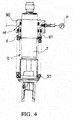
FIG. 4 is a front view showing a conventional damper partially cut out. -
FIG. 5 is a front view showing a conventional damper partially cut out. - Hereinafter, an embodiment of the present invention will be described with reference to the accompanying drawings.
-
FIG. 1 is a front view showing a damper D partially cut out, on which a vehicleheight adjusting apparatus 100 according to the present embodiment is mounted. The same reference numerals given through several drawings denote the same or corresponding components, respectively. - As shown in
FIG. 1 , the vehicleheight adjusting apparatus 100 includes: an annularmovable spring receiver 1 in sliding contact with aguide surface 30 formed on an outer periphery of an outer tube T of the damper D, the annularmovable spring receiver 1 being configured to support one side end (an upper end inFIG. 1 ) of a suspension spring S1 biasing the damper D in an expansion direction; a driving mechanism M configured to drive themovable spring receiver 1 in an axial direction of the damper D; an auxiliary spring S2 configured to bias themovable spring receiver 1 to a suspension spring side; and adust cover 2A configured to cover a portion on theguide surface 30 with which themovable spring receiver 1 is in sliding contact. Thedust cover 2A is held on the outer tube T by means of a spring force of the auxiliary spring S2. - The damper D is an inverted damper that includes: the outer tube T connected to a vehicle body side via a vehicle body side bracket B1; and a piston rod R connected to a wheel side via a wheel side bracket B2. The piston rod R is movably inserted into the outer tube T in the axial direction, and the damper D is expanded and contracted by the piston rod R going into/out of the outer tube T.
- The damper D generates a predetermined damping force with expansion/contraction thereof to suppress an expansion/contraction motion of the suspension spring S1. Since any configuration may be adopted as a configuration in which the damper D generates the damping force, detailed explanation of the configuration is omitted. Further, the damper D may be an upright damper in which a piston rod R is connected to a vehicle body side and an outer tube T is connected to a wheel side.
- A portion from a substantial center of the outer tube T to the vehicle body side (an upper side in
FIG. 1 ) is covered by acylindrical guide tube 3. Aguide surface 30 formed smoothly is formed on an outer peripheral surface of theguide tube 3. Themovable spring receiver 1 and ajack piston 7 which will be described later are in sliding contact with theguide surface 30 and can be smoothly moved along theguide tube 3. - A support member 4 projecting outward from the outer tube T is fixed on a vehicle body side end of the outer tube T (the upper end in
FIG. 1 ). It is only necessary that the support member 4 is connected to the outer tube T so as not to move, and as a method of connecting the support member 4 to the outer tube T, an appropriate known method such as integral forming, screwing, fitting and the like may be adopted. - The suspension spring S1 made of a coil spring is mounted on an outer periphery of the damper D. The suspension spring S1 is interposed between the
movable spring receiver 1 connected to the vehicle body side and a fixed spring receiver 5 connected to the wheel side to bias themovable spring receiver 1 and the fixed spring receiver 5 in a direction to be separated from each other. The suspension spring S1 biases the damper D in the expansion direction in which the piston rod R goes out of the outer tube T. - The
movable spring receiver 1 is formed in an annular manner and in sliding contact with theguide surface 30 of theguide tube 3. Themovable spring receiver 1 is movable in the axial direction of the damper D, and constitutes the vehicleheight adjusting apparatus 100 for adjusting the vehicle height. The fixed spring receiver 5 is formed in an annular manner. The fixed spring receiver 5 is supported by the wheel side bracket B2, and is pressed onto the wheel side bracket B2 by means of thesuspension spring S 1 so that movement thereof in the axial direction is regulated. - The vehicle
height adjusting apparatus 100 includes: themovable spring receiver 1; the driving mechanism M configured to drive themovable spring receiver 1 in the axial direction of the damper D; the auxiliary spring S2 configured to bias themovable spring receiver 1 to the suspension spring side; and thedust cover 2A configured to cover the portion in theguide surface 30 with which themovable spring receiver 1 is in sliding contact. - As shown in
FIG. 2 , themovable spring receiver 1 constituting the vehicleheight adjusting apparatus 100 includes: anannular support portion 10 configured to support a vehicle body side end (one side end) of the suspension spring S1; and acylindrical guide portion 11 configured to stand substantially perpendicularly from an inner peripheral edge of a suspension spring side surface (a lower surface inFIG. 2 ) of thesupport portion 10. Theguide portion 11 supports an inner periphery of the vehicle body side end portion (one side end portion) of the suspension spring S1. A thickness of aninner periphery portion 10a in thesupport portion 10 is formed so as to be larger than a thickness of anouter periphery portion 10b. As a result, theinner periphery portion 10a protrudes to the side opposite to the suspension spring (an upper side inFIG. 2 ) compared with theouter periphery portion 10b. - The driving mechanism M constituting the vehicle
height adjusting apparatus 100 and driving themovable spring receiver 1 includes: ahousing 6 fixed to the outer periphery of the outer tube T and on the side opposite to the suspension spring of the movable spring receiver 1 (upper sides inFIGS. 1 and2 ); a jack chamber J formed between thehousing 6 and theguide surface 30 and filled with an operating fluid; ajack piston 7 brought into contact with the side opposite to the suspension spring of the movable spring receiver 1 (upper sides inFIGS. 1 and2 ) and configured to be inserted movably between thehousing 6 and theguide surface 30 to close an opening on the suspension spring side of the jack chamber J (lower sides inFIGS. 1 and2 ); and the pump P (FIG. 1 ) configured to suction and discharge the operating fluid with respect to the jack chamber J. - The
housing 6 constituting the driving mechanism M is formed into a bottomed cylindrical shape as shown inFIG. 2 . Thehousing 6 includes anannular bottom portion 60 and acylindrical portion 61 having a cylindrical shape. Thecylindrical portion 61 stands substantially perpendicularly from the suspension spring side surface (the lower surface inFIG. 2 ) of thebottom portion 60. Thehousing 6 is arranged so as to cause thebottom portion 60 to face the vehicle body side (the upper side inFIG. 2 ) and to cause thecylindrical portion 61 to face the suspension spring side (a lower side inFIG. 2 ). Moreover, thehousing 6 is pressed onto the support member 4 by the suspension spring S1, and is fixed in a locked state. Namely, thehousing 6 is fixed to the outer tube T via the support member 4. - The
cylindrical portion 61 of thehousing 6 is arranged so that a predetermined gap is formed between thecylindrical portion 61 and an outer periphery of theguide surface 30 of theguide tube 3. In this gap, a non-compressive operating fluid is stored, and the annular jack chamber J is formed. - An
inner periphery portion 60a of thebottom portion 60 in thehousing 6 protrudes inward from thecylindrical portion 61, and anannular seal 62 is mounted on an inner periphery of theinner periphery portion 60a. Theseal 62 is in close contact with theguide surface 30 of theguide tube 3. For this reason, theinner periphery portion 60a of thebottom portion 60 closes an opening on the side opposite to the suspension spring (the upper side inFIG. 2 ) of the jack chamber J in a liquid-tight manner, and prevents the operating fluid in the jack chamber J from flowing out of a gap between thebottom portion 60 of thehousing 6 and theguide tube 3. Anouter periphery portion 60b of thebottom portion 60 of thehousing 6 projects outward from thecylindrical portion 61. - The
jack piston 7 constituting the driving mechanism M includes: anannular piston portion 70 configured to be inserted movably between thecylindrical portion 61 of thehousing 6 and theguide surface 30 of theguide tube 3 to close an opening on the suspension spring side (the lower side inFIG. 2 ) of the jack chamber J; and anextended portion 71 continuing to the suspension spring side (the lower side inFIG. 2 ) of thepiston portion 70. -
Annular seals piston portion 70. The innerperipheral side seal 72 is in sliding contact with theguide surface 30 of theguide tube 3, while the outerperipheral side seal 73 is in sliding contact with the inner peripheral surface of thecylindrical portion 61. Namely, thejack piston 7 is in sliding contact with theguide surface 30 of theguide tube 3 via the innerperipheral side seal 72, and is in sliding contact with the inner peripheral surface of thecylindrical portion 61 via the outerperipheral side seal 73. As a result, thejack piston 7 closes the opening on the suspension spring side (the lower side inFIG. 2 ) of the jack chamber J in the liquid-tight manner. - The
extended portion 71 is configured so that a suspension springside end portion 71 a of the extendedportion 71 protrudes downward compared with thecylindrical portion 61 of thehousing 6 even in a case where themovable spring receiver 1 retreats the most and thejack piston 7 is at a jack minimum position where thejack piston 7 enters thehousing 6 the most. Namely, an axial size of thejack piston 7 is set so that the suspension springside end portion 71a of the extendedportion 71 always protrudes from thehousing 6. - As shown in
FIG. 1 , the pump P constituting the driving mechanism M is connected to the jack chamber J through a hose H, and is driven by a motor (not shown) to suction and discharge the operating fluid with respect to the jack chamber J. Since any constitution may be adopted as the constitution of the pump P, detailed explanation of the configuration of the pump P is omitted. Further, the pump P may be an electric pump driven by the motor, or may be a manual pump manually driven. - The auxiliary spring S2 constituting the vehicle
height adjusting apparatus 100 together with the driving mechanism M is made of a coil spring. As shown inFIG. 2 , the auxiliary spring S2 is arranged on an outer periphery of thecylindrical portion 61 of thehousing 6. The auxiliary spring S2 is interposed between theouter periphery portion 10b of thesupport portion 10 of themovable spring receiver 1 and theouter periphery portion 60b of thebottom portion 60 of thehousing 6. The auxiliary spring S2 is arranged in series with the suspension spring S1, and biases themovable spring receiver 1 to the suspension spring side (the lower side inFIG. 2 ) to compress the suspension spring S1. - Hereinafter, a force acting on the suspension spring S1 or the auxiliary spring S2 is referred to as a load. A load of the auxiliary spring S2 becomes the largest in a case where the
movable spring receiver 1 retreats the most and thejack piston 7 is at the jack minimum position where thejack piston 7 enters thehousing 6 the most. Hereinafter, the load of the auxiliary spring S2 at this time is referred to as a maximum load at assembling of the auxiliary spring S2. On the other hand, a load of the suspension spring S1 becomes the smallest when thejack piston 7 is at the jack minimum position and the damper D is expanded the most. Hereinafter, the load of the suspension spring S1 at this time is referred to as a minimum load at assembling of the suspension spring. - The maximum load at assembling of the auxiliary spring S2 is set so as to be smaller than the minimum load at assembling of the suspension spring S1. As a result, since the load of the auxiliary spring S2 is always smaller than the load of the suspension spring S1, the
movable spring receiver 1 is always pressed onto the suspension springside end portion 71a of thejack piston 7 by means of the suspension spring S1 and is maintained in a contact state. - The
dust cover 2A constituting the vehicleheight adjusting apparatus 100 includes: aseat portion 20 formed into an annular plate shape and with which the one side end of the auxiliary spring S2 (the upper end inFIG. 2 ) is brought into contact; and acylindrical cover portion 21 standing from an outer peripheral edge of theseat portion 20. Thedust cover 2A is arranged so as to cause theseat portion 20 to face theouter periphery portion 60b side of thebottom portion 60 of thehousing 6, and arranged so that thecover portion 21 covers themovable spring receiver 1 and the auxiliary spring S2. - The auxiliary spring S2 is compressed by the suspension spring S1 via the
movable spring receiver 1. For this reason, theseat portion 20 is pressed onto thebottom portion 60 of thehousing 6 by means of a spring force (restoring force, reaction force) of the auxiliary spring S2, and theseat portion 20 is sandwiched by the auxiliary spring S2 and thebottom portion 60 of thehousing 6. Thus, thedust cover 2A is held on the outer tube T of the damper D by means of the spring force of the auxiliary spring S2. - A length of the
cover portion 21 of thedust cover 2A is set so that themovable spring receiver 1 does not protrude from thecover portion 21 even if themovable spring receiver 1 is moved. Namely, thecover portion 21 covers an entire portion of theguide surface 30 with which themovable spring receiver 1 is in sliding contact. - Next, an operation of the vehicle
height adjusting apparatus 100 according to the present embodiment will be described. - A state of the vehicle
height adjusting apparatus 100 in which themovable spring receiver 1 advances the most and thejack piston 7 is at a jack maximum position where thejack piston 7 retreats from thehousing 6 the most is shown at the right side of a center line X inFIG. 1 . When the pump P is driven so as to supply the operating fluid to the jack chamber J, thejack piston 7 is pushed out of thehousing 6. For this reason, the outer tube T is pushed up to the upper side inFIG. 1 and the damper D is expanded, whereby the vehicle height is raised. - A state of the vehicle
height adjusting apparatus 100 in which themovable spring receiver 1 retreats the most and thejack piston 7 is at the jack minimum position where thejack piston 7 enters thehousing 6 the most is shown at the left side of the center line X inFIG. 1 . When the pump P is driven so as to discharge the operating fluid from the jack chamber J, thejack piston 7 is pushed into thehousing 6. For this reason, the outer tube T is moved to the lower side inFIG. 1 , and the damper D is compressed, whereby the vehicle height is lowered. - Next, an operation and an effect of the vehicle
height adjusting apparatus 100 according to the present embodiment will be described. - The vehicle
height adjusting apparatus 100 includes: the annularmovable spring receiver 1 in sliding contact with theguide surface 30 formed on the outer periphery of the outer tube T of the damper D, the annularmovable spring receiver 1 being configured to support the one side end (the upper end inFIG. 1 ) of the suspension spring S1 biasing the damper D in the expansion direction; the driving mechanism M configured to drive themovable spring receiver 1 in the axial direction of the damper D; the auxiliary spring S2 configured to bias themovable spring receiver 1 to the suspension spring side; and thedust cover 2A configured to cover the portion on theguide surface 30 with which themovable spring receiver 1 is in sliding contact. Thedust cover 2A is held on the outer tube T by means of the spring force of the auxiliary spring S2. - Therefore, in the vehicle
height adjusting apparatus 100 provided with the auxiliary spring S2, thedust cover 2A is mounted by using the spring force of the auxiliary spring S2. For this reason, mounting of thedust cover 2A can be facilitated. Further, since the vehicleheight adjusting apparatus 100 is provided with the auxiliary spring S2, themovable spring receiver 1 can be driven by means of a smaller force in a case where adjustment is made in the direction in which the vehicle height is raised. Moreover, since the vehicleheight adjusting apparatus 100 is provided with thedust cover 2A, it is possible to suppress dusts from adhering onto theguide surface 30 with which themovable spring receiver 1 is in sliding contact, and themovable spring receiver 1 can be smoothly moved along theguide surface 30. - Moreover, the driving mechanism M includes: the
housing 6 fixed to the outer periphery of the outer tube T and on the side opposite to the suspension spring of the movable spring receiver 1 (the upper side inFIG. 1 ); the jack chamber J formed between thehousing 6 and theguide surface 30 and filled with the operating fluid; thejack piston 7 brought into contact with the side opposite to the suspension spring (the upper side inFIG. 1 ) of themovable spring receiver 1, and configured to be inserted movably between thehousing 6 and theguide surface 30 to close the opening on the suspension spring side (the lower side inFIG. 1 ) of the jack chamber J; and the pump P configured to suction and discharge the operating fluid with respect to the jack chamber J. - Therefore, by suctioning and discharging the operating fluid with respect to the jack chamber J to cause the
jack piston 7 to go into/from thehousing 6, themovable spring receiver 1 can be driven easily via thejack piston 7. - Moreover, the
seals jack piston 7, and thejack piston 7 is in sliding contact with theguide surface 30 via theseal 72. Since thedust cover 2A covers the portion of theguide surface 30 with which themovable spring receiver 1 is in sliding contact, it is possible to suppress theseal 72 from being scratched due to the dust adhering to theguide surface 30, and this makes it possible to improve durability of theseal 72. - Moreover, the
housing 6 is formed into a bottomed cylindrical shape, and includes: theannular bottom portion 60 mounted on the outer periphery of theguide surface 30 in the liquid-tight manner; and thecylindrical portion 61 standing from the suspension spring side surface (the lower surface inFIG. 2 ) of thebottom portion 60. The jack chamber J is defined between thecylindrical portion 61 and theguide surface 30. Theouter periphery portion 60b of thebottom portion 60 projects outward from thecylindrical portion 61, and the auxiliary spring S2 is interposed between theouter periphery portion 60b which is the outer periphery of thecylindrical portion 61 and themovable spring receiver 1. - Therefore, a mounting work of the auxiliary spring S2 can be facilitated. Further, since the auxiliary spring S2 is arranged on an outer periphery of the jack chamber J, the vehicle
height adjusting apparatus 100 can be formed compactly. - Moreover, the
dust cover 2A includes: theseat portion 20 formed into an annular plate shape and with which the one side end (the upper end inFIG. 2 ) of the auxiliary spring S2 is brought into contact; and thecylindrical cover portion 21 standing from the outer peripheral edge of theseat portion 20. Theseat portion 20 is sandwiched by the auxiliary spring S2 and theouter periphery portion 60b of thebottom portion 60 in thehousing 6, and thecover portion 21 covers themovable spring receiver 1 and the auxiliary spring S2. - Therefore, since the entire portion of the
guide surface 30 with which themovable spring receiver 1 is in sliding contact can be covered by thedust cover 2A, smooth movement of themovable spring receiver 1 can be carried out more reliably. Further, since thedust cover 2A covers themovable spring receiver 1, the auxiliary spring S2, thejack piston 7, and the jack chamber J, it is possible to suppress dusts from adhering on themovable spring receiver 1, the auxiliary spring S2, thejack piston 7, and the jack chamber J. - Moreover, since the auxiliary spring S2 is arranged inside the
dust cover 2A, a coil diameter of the auxiliary spring S2 can be made smaller compared with the case in which the auxiliary spring S2 is arranged outside thedust cover 2A, and this makes it possible to suppress a size increase of the auxiliary spring S2. - Moreover, since the vehicle
height adjusting apparatus 100 is assembled by mounting thehousing 6, thedust cover 2A, the auxiliary spring S2, and themovable spring receiver 1 on the outer periphery of theguide surface 30 in this order, assembling of the vehicleheight adjusting apparatus 100 can be carried out easily. - Moreover, since the
cover portion 21 of thedust cover 2A is directed downward, it is possible to suppress entry of water, dusts and the like into thedust cover 2A. - Next, a second embodiment will be described.
-
FIG. 3 is an enlarged view showing a major portion of a damper, on which a vehicleheight adjusting apparatus 200 according to the present embodiment is mounted, in an enlarged manner. In the vehicleheight adjusting apparatus 200 according to the present embodiment, only a configuration of adust cover 2B is different from that of the first embodiment, and the other configurations are similar to those of the first embodiment. Therefore, only thedust cover 2B will be explained, and explanation for the other configurations will be omitted. InFIG. 3 , the same reference numerals are given to the same configurations as those in the first embodiment. - As shown in
FIG. 3 , adust cover 2B includes: aseat portion 22 formed into an annular plate shape and with which one side end (a lower end inFIG. 3 ) of an auxiliary spring S2 is brought into contact; and acylindrical cover portion 23 standing from an inner peripheral edge of theseal portion 22. Thedust cover 2B is arranged so as to cause theseat portion 22 to face amovable spring receiver 1 side, and arranged so that thecover portion 23 covers acylindrical portion 61 of ahousing 6. - The auxiliary spring S2 is compressed by the suspension spring S1 via the
movable spring receiver 1. For this reason, theseat portion 22 is pressed onto asupport portion 10 of themovable spring receiver 1 by means of the spring force (restoring force, reaction force) of the auxiliary spring S2, and theseat portion 22 is sandwiched by the auxiliary spring S2 and thesupport portion 10 of themovable spring receiver 1. Thus, thedust cover 2B is held on the outer tube T of the damper D by means of the spring force of the auxiliary spring S2. - The
dust cover 2B is moved together with themovable spring receiver 1. A length of thecover portion 23 of thedust cover 2B is set so that a state overlapped with thecylindrical portion 61 of thehousing 6 can be maintained even if thedust cover 2B is moved together with themovable spring receiver 1. As a result, thecover portion 23 of thedust cover 2B can always cover the portion at the jack chamber side (an upper side inFIG. 3 ) of theguide surface 30, with which themovable spring receiver 1 is in sliding contact, regardless of the sliding position of themovable spring receiver 1. - Next, an operation and an effect of the vehicle
height adjusting apparatus 200 according to the present embodiment will be described. - Since the
dust cover 2B is held on the outer tube T of the damper D by means of the spring force of the auxiliary spring S2, mounting of thedust cover 2B can also be carried out easily even in the vehicleheight adjusting apparatus 200 provided with the auxiliary spring S2. Further, by providing thedust cover 2B, it is possible to suppress dusts from adhering to theguide surface 30 with which themovable spring receiver 1 is in sliding contact, and this makes it possible to move themovable spring receiver 1 smoothly along theguide surface 30. - Moreover, the
dust cover 2B includes: theseat portion 22 formed into an annular plate shape and with which the one side end (the lower end inFIG. 3 ) of the auxiliary spring S2 is brought into contact; and thecylindrical cover portion 23 standing from the inner peripheral edge of theseat portion 22. Theseat portion 22 is sandwiched by the auxiliary spring S2 and themovable spring receiver 1, and thecylindrical portion 61 of thehousing 6 is covered by thecover portion 23. - Therefore, since the jack chamber side (the upper side in
FIG. 3 ) of a portion of theguide surface 30 with which themovable spring receiver 1 is in sliding contact can be covered by thedust cover 2B, it is possible to move themovable spring receiver 1 smoothly. Further, since thedust cover 2B covers themovable spring receiver 1, thejack piston 7, and the jack chamber J, it is possible to suppress adhesion of dusts to these portions. - The embodiment of the present invention has been described above, but the above embodiment is merely examples of application of the present invention, and the technical scope of the present invention is not limited to the specific configurations of the above embodiment.
- For example, in the embodiment described above, the
guide surface 30 is formed on the outer peripheral surface of theguide tube 3 mounted on the outer tube T of the damper D. However, a part of the outer peripheral surface of the outer tube T may be configured so as to function as theguide surface 30. - Moreover, in the embodiment described above, the suspension spring S1 and the auxiliary spring S2 are constituted by a coil spring. However, either one of or both of the suspension spring S1 and the auxiliary spring S2 may be constituted by an elastic body such as an air spring, a rubber or the like.
- Moreover, in the embodiment described above, the driving mechanism M includes the jack chamber J, the
jack piston 7 and the pump P, and drives themovable spring receiver 1 via thejack piston 7 by suctioning and discharging the operating fluid with respect to the jack chamber J by means of the pump P. However, a constitution for driving themovable spring receiver 1 is not limited to the above configuration, and can be selected as appropriate. - Moreover, in the embodiment described above, the
housing 6 includes thebottom portion 60 and thecylindrical portion 61, the jack chamber J is formed inside thecylindrical portion 61, and the auxiliary spring S2 is mounted on the outer side of thecylindrical portion 61. However, a shape of thehousing 6 and a mounting position of the auxiliary spring S2 are not limited to those described above, and can be selected as appropriate. - Moreover, in the embodiment described above, the
dust covers seat portions cylindrical cover portions dust covers dust cover 2A of the first embodiment may be configured to be arranged so as to cause theseat portion 20 to face themovable spring receiver 1 side and so that theseat portion 20 is sandwiched by the auxiliary spring S2 and themovable spring receiver 1. - Moreover, a seal may be interposed between the
dust cover 2A and themovable spring receiver 1 in the first embodiment or between thedust cover 2B and thecylindrical portion 61 of thehousing 6 in the second embodiment. In this case, it is possible to suppress dusts from entering thedust covers - The present application claims priority based on Japanese Patent Application No.
2012-266948
Claims (5)
- A vehicle height adjusting apparatus, comprising:an annular movable spring receiver in sliding contact with a guide surface formed on an outer periphery of an outer tube of a damper, the movable spring receiver being configured to support one side end of a suspension spring, the suspension spring biasing the damper in an expansion direction;a driving mechanism configured to drive the movable spring receiver in an axial direction of the damper;an auxiliary spring configured to bias the movable spring receiver to the suspension spring side; anda dust cover configured to cover a portion on the guide surface, the movable spring receiver being in sliding contact with the guide surface in the portion,wherein the dust cover is held on the outer tube by means of a spring force of the auxiliary spring.
- The vehicle height adjusting apparatus according to claim 1,
wherein the driving mechanism includes:a housing fixed to the outer periphery of the outer tube and on a side opposite to the suspension spring of the movable spring receiver;a jack chamber formed between the housing and the guide surface, the jack chamber being filled with an operating fluid;a jack piston brought into contact with a side opposite to the suspension spring of the movable spring receiver, the jack piston being configured to be inserted movably between the housing and the guide surface, the jack piston closing an opening on the suspension spring side of the jack chamber; anda pump configured to suction and discharge the operating fluid to and from the jack chamber. - The vehicle height adjusting apparatus according to claim 2,
wherein the housing is formed into a bottomed cylindrical shape, the housing including an annular bottom portion mounted on an outer periphery of the guide surface in a liquid-tight manner and a cylindrical portion having a cylindrical shape, the cylindrical portion standing from a surface on the suspension spring side of the bottom portion, the jack chamber being defined between the cylindrical portion and the guide surface,
wherein an outer periphery portion of the bottom portion projects outward from the cylindrical portion, and
wherein the auxiliary spring is interposed between the outer periphery portion of the bottom portion which is an outer periphery of the cylindrical portion and the movable spring receiver. - The vehicle height adjusting apparatus according to claim 3,
wherein the dust cover is formed into an annular plate shape, the dust cover including a seat portion with which one side end of the auxiliary spring is brought into contact and a cylindrical cover portion standing from an outer peripheral edge of the seat portion,
wherein the seat portion is sandwiched by the auxiliary spring and the outer periphery portion of the bottom portion of the housing, and
wherein the movable spring receiver and the auxiliary spring are covered by the cover portion. - The vehicle height adjusting apparatus according to claim 3,
wherein the dust cover is formed into an annular plate shape, the dust cover including a seat portion with which one side end of the auxiliary spring is brought into contact and a cylindrical cover portion standing from an inner peripheral edge of the seat portion,
wherein the seat portion is sandwiched by the auxiliary spring and the movable spring receiver, and
wherein the cylindrical portion of the housing is covered by the cover portion.
Applications Claiming Priority (2)
| Application Number | Priority Date | Filing Date | Title |
|---|---|---|---|
| JP2012266948A JP5936127B2 (en) | 2012-12-06 | 2012-12-06 | Vehicle height adjustment device |
| PCT/JP2013/082576 WO2014088027A1 (en) | 2012-12-06 | 2013-12-04 | Vehicle height adjustment device |
Publications (2)
| Publication Number | Publication Date |
|---|---|
| EP2930394A1 true EP2930394A1 (en) | 2015-10-14 |
| EP2930394A4 EP2930394A4 (en) | 2016-10-12 |
Family
ID=50883445
Family Applications (1)
| Application Number | Title | Priority Date | Filing Date |
|---|---|---|---|
| EP13860127.3A Withdrawn EP2930394A4 (en) | 2012-12-06 | 2013-12-04 | DEVICE FOR ADJUSTING THE HEIGHT OF THE VEHICLE |
Country Status (5)
| Country | Link |
|---|---|
| US (1) | US9527365B2 (en) |
| EP (1) | EP2930394A4 (en) |
| JP (1) | JP5936127B2 (en) |
| CN (1) | CN104838166B (en) |
| WO (1) | WO2014088027A1 (en) |
Cited By (1)
| Publication number | Priority date | Publication date | Assignee | Title |
|---|---|---|---|---|
| WO2024085758A1 (en) * | 2022-10-21 | 2024-04-25 | Rrs Holding B.V. | Shock absorber, and an assembly of a seat construction and a shock absorber connected thereto |
Families Citing this family (17)
| Publication number | Priority date | Publication date | Assignee | Title |
|---|---|---|---|---|
| JP5936127B2 (en) * | 2012-12-06 | 2016-06-15 | Kyb株式会社 | Vehicle height adjustment device |
| DE102012112717B4 (en) * | 2012-12-20 | 2015-05-13 | Thyssenkrupp Bilstein Gmbh | Suspension leg for a motor vehicle with a height adjustment device |
| DE102015208785B4 (en) * | 2015-05-12 | 2020-03-19 | Zf Friedrichshafen Ag | Adjustable spring support |
| JP2017032014A (en) * | 2015-07-30 | 2017-02-09 | Kyb株式会社 | Shock absorber |
| JP6613190B2 (en) * | 2016-03-28 | 2019-11-27 | Kyb株式会社 | Shock absorber |
| JP6613189B2 (en) * | 2016-03-28 | 2019-11-27 | Kyb株式会社 | Shock absorber |
| JP6788984B2 (en) * | 2016-03-28 | 2020-11-25 | Kyb株式会社 | Buffer |
| US10639954B2 (en) * | 2016-09-23 | 2020-05-05 | Jay O'Connell | Multi-link suspension system |
| CN107933758A (en) * | 2017-11-20 | 2018-04-20 | 宁波超锐特工贸有限公司 | A kind of beach buggy cushion damping device |
| DE102018212109A1 (en) * | 2018-07-20 | 2020-01-23 | Bayerische Motoren Werke Aktiengesellschaft | Height adjustable spring assembly for a vehicle |
| CN109027109A (en) * | 2018-09-27 | 2018-12-18 | 浙江众泰汽车制造有限公司 | A kind of vehicle shock absorber structure |
| US11021031B2 (en) | 2018-10-29 | 2021-06-01 | Polaris Industries Inc. | Suspension pre-load adjustment system |
| US11102654B2 (en) | 2018-11-01 | 2021-08-24 | Polaris Industries Inc. | Connected helmet system and method of operating the same |
| DE102019119419B4 (en) * | 2019-07-17 | 2023-01-12 | Ktm Ag | Pneumatically actuable adjustment device for loading a spring device of a spring damper device having a tubular body |
| US11400790B2 (en) * | 2020-01-30 | 2022-08-02 | Schaeffler Technologies AG & Co. KG | Concentric hydraulic ride height actuator for a motor vehicle |
| DE112020003952B4 (en) * | 2020-06-25 | 2024-02-01 | Hitachi Astemo, Ltd. | Suspension device and saddle type vehicle |
| US20250153526A1 (en) | 2022-02-14 | 2025-05-15 | Ree Automotive Ltd. | Adaptive suspension system |
Family Cites Families (14)
| Publication number | Priority date | Publication date | Assignee | Title |
|---|---|---|---|---|
| JPS57129942A (en) | 1981-02-04 | 1982-08-12 | Showa Mfg Co Ltd | Dust boots device in shock absorber |
| JPH10292841A (en) * | 1997-04-18 | 1998-11-04 | Kayaba Ind Co Ltd | Top cover structure |
| JPH10299811A (en) * | 1997-04-25 | 1998-11-13 | Showa:Kk | Vehicle height adjusting device and method of using the same |
| JP3770435B2 (en) * | 1997-12-10 | 2006-04-26 | 本田技研工業株式会社 | Cylindrical shock absorber with cover |
| JPH11182609A (en) | 1997-12-19 | 1999-07-06 | Kayaba Ind Co Ltd | Suspension spring force adjusting device for oil damper |
| DE10123491A1 (en) * | 2001-05-15 | 2002-11-21 | Porsche Ag | Adjustable shock absorber for a motor vehicle |
| JP4666586B2 (en) * | 2005-02-17 | 2011-04-06 | 株式会社ショーワ | Hydraulic shock absorber |
| JP4500786B2 (en) * | 2006-04-27 | 2010-07-14 | カヤバ工業株式会社 | Shock absorber |
| DE102007040734B4 (en) * | 2007-08-29 | 2009-05-07 | Audi Ag | Suspension strut for a suspension of motor vehicles |
| CN102026835B (en) * | 2008-12-24 | 2013-08-21 | 萱场工业株式会社 | Vehicle height adjusting device |
| JP5379468B2 (en) | 2008-12-24 | 2013-12-25 | カヤバ工業株式会社 | Vehicle height adjustment device |
| DE102010036238A1 (en) * | 2010-09-03 | 2012-03-08 | Magna Steyr Fahrzeugtechnik Ag & Co. Kg | Shock absorber unit e.g. tie rod, for use in wheel suspension system for vertical adjustment of motor car, has locking pin in energized state of actuator during open position and in current-free state of actuator during blocking position |
| JP5936125B2 (en) * | 2012-11-20 | 2016-06-15 | Kyb株式会社 | Vehicle height adjustment device and method of assembling vehicle height adjustment device |
| JP5936127B2 (en) * | 2012-12-06 | 2016-06-15 | Kyb株式会社 | Vehicle height adjustment device |
-
2012
- 2012-12-06 JP JP2012266948A patent/JP5936127B2/en not_active Expired - Fee Related
-
2013
- 2013-12-04 WO PCT/JP2013/082576 patent/WO2014088027A1/en not_active Ceased
- 2013-12-04 EP EP13860127.3A patent/EP2930394A4/en not_active Withdrawn
- 2013-12-04 US US14/650,261 patent/US9527365B2/en not_active Expired - Fee Related
- 2013-12-04 CN CN201380063441.XA patent/CN104838166B/en not_active Expired - Fee Related
Cited By (2)
| Publication number | Priority date | Publication date | Assignee | Title |
|---|---|---|---|---|
| WO2024085758A1 (en) * | 2022-10-21 | 2024-04-25 | Rrs Holding B.V. | Shock absorber, and an assembly of a seat construction and a shock absorber connected thereto |
| NL2033373B1 (en) * | 2022-10-21 | 2024-05-08 | Rrs Holding B V | Shock absorber, and an assembly of a seat construction and a shock absorber connected thereto |
Also Published As
| Publication number | Publication date |
|---|---|
| US9527365B2 (en) | 2016-12-27 |
| JP2014114825A (en) | 2014-06-26 |
| US20150314664A1 (en) | 2015-11-05 |
| WO2014088027A1 (en) | 2014-06-12 |
| CN104838166A (en) | 2015-08-12 |
| JP5936127B2 (en) | 2016-06-15 |
| CN104838166B (en) | 2017-02-01 |
| EP2930394A4 (en) | 2016-10-12 |
Similar Documents
| Publication | Publication Date | Title |
|---|---|---|
| US9527365B2 (en) | Vehicle height adjusting apparatus | |
| US9352631B2 (en) | Vehicle height adjusting device and assembling method for vehicle height adjusting device | |
| JP4590028B2 (en) | Vehicle height adjustment suspension | |
| US8186071B2 (en) | Co-ordinate measuring machine with a device for balancing the weight of a vertically mobile member | |
| US11648811B2 (en) | Adjustable gas spring system | |
| JPWO2020016916A1 (en) | Hydraulic shock absorber | |
| US9328792B2 (en) | Hydraulic shock absorber | |
| CN111089584A (en) | Convenient vehicle-mounted navigation equipment with shock-absorbing function | |
| CN113732660B (en) | Auxiliary material press fitting device | |
| WO2014065310A1 (en) | Wheel height adjustment apparatus | |
| US20060213733A1 (en) | Vehicle support system and method of supporting a vehicle body | |
| CN211474737U (en) | Secondary buffer device and secondary buffer shock absorber | |
| CN210830290U (en) | Shock absorber for automobile air bag | |
| CN223331024U (en) | External auxiliary air bag type shock absorber | |
| JP7644806B1 (en) | Shock absorber with height adjustment function | |
| JPH1044738A (en) | Height adjustment device | |
| CN222046482U (en) | Hydraulic shock absorber and vehicle | |
| CN111734768A (en) | Secondary shock absorber | |
| JP5074807B2 (en) | Air pump | |
| JP2005351470A (en) | Suspension device and cycle using it | |
| CN117000943A (en) | Riveting device for instrument assembly | |
| CN121773278A (en) | Vehicle height adjusting device | |
| JPH08282238A (en) | Car height adjusting device | |
| JP5952695B2 (en) | Suspension device | |
| CN114161370A (en) | Intelligent assembly table for electric vehicle installation |
Legal Events
| Date | Code | Title | Description |
|---|---|---|---|
| PUAI | Public reference made under article 153(3) epc to a published international application that has entered the european phase |
Free format text: ORIGINAL CODE: 0009012 |
|
| 17P | Request for examination filed |
Effective date: 20150703 |
|
| AK | Designated contracting states |
Kind code of ref document: A1 Designated state(s): AL AT BE BG CH CY CZ DE DK EE ES FI FR GB GR HR HU IE IS IT LI LT LU LV MC MK MT NL NO PL PT RO RS SE SI SK SM TR |
|
| AX | Request for extension of the european patent |
Extension state: BA ME |
|
| RAP1 | Party data changed (applicant data changed or rights of an application transferred) |
Owner name: KYB CORPORATION |
|
| DAX | Request for extension of the european patent (deleted) | ||
| RA4 | Supplementary search report drawn up and despatched (corrected) |
Effective date: 20160908 |
|
| RIC1 | Information provided on ipc code assigned before grant |
Ipc: B62K 25/04 20060101ALI20160902BHEP Ipc: F16F 9/32 20060101ALI20160902BHEP Ipc: F16F 9/38 20060101ALI20160902BHEP Ipc: B62K 25/08 20060101ALI20160902BHEP Ipc: F16F 9/46 20060101AFI20160902BHEP |
|
| STAA | Information on the status of an ep patent application or granted ep patent |
Free format text: STATUS: THE APPLICATION HAS BEEN WITHDRAWN |
|
| 18W | Application withdrawn |
Effective date: 20181212 |