EP2930377A1 - Struts and methods utilizing a compression collar - Google Patents
Struts and methods utilizing a compression collar Download PDFInfo
- Publication number
- EP2930377A1 EP2930377A1 EP15161315.5A EP15161315A EP2930377A1 EP 2930377 A1 EP2930377 A1 EP 2930377A1 EP 15161315 A EP15161315 A EP 15161315A EP 2930377 A1 EP2930377 A1 EP 2930377A1
- Authority
- EP
- European Patent Office
- Prior art keywords
- conical section
- composite tube
- locking ring
- various embodiments
- distal end
- Prior art date
- Legal status (The legal status is an assumption and is not a legal conclusion. Google has not performed a legal analysis and makes no representation as to the accuracy of the status listed.)
- Granted
Links
Images




Classifications
-
- E—FIXED CONSTRUCTIONS
- E04—BUILDING
- E04C—STRUCTURAL ELEMENTS; BUILDING MATERIALS
- E04C3/00—Structural elongated elements designed for load-supporting
- E04C3/30—Columns; Pillars; Struts
- E04C3/36—Columns; Pillars; Struts of materials not covered by groups E04C3/32 or E04C3/34; of a combination of two or more materials
-
- F—MECHANICAL ENGINEERING; LIGHTING; HEATING; WEAPONS; BLASTING
- F16—ENGINEERING ELEMENTS AND UNITS; GENERAL MEASURES FOR PRODUCING AND MAINTAINING EFFECTIVE FUNCTIONING OF MACHINES OR INSTALLATIONS; THERMAL INSULATION IN GENERAL
- F16B—DEVICES FOR FASTENING OR SECURING CONSTRUCTIONAL ELEMENTS OR MACHINE PARTS TOGETHER, e.g. NAILS, BOLTS, CIRCLIPS, CLAMPS, CLIPS OR WEDGES; JOINTS OR JOINTING
- F16B7/00—Connections of rods or tubes, e.g. of non-circular section, mutually, including resilient connections
- F16B7/02—Connections of rods or tubes, e.g. of non-circular section, mutually, including resilient connections with conical parts
-
- F—MECHANICAL ENGINEERING; LIGHTING; HEATING; WEAPONS; BLASTING
- F16—ENGINEERING ELEMENTS AND UNITS; GENERAL MEASURES FOR PRODUCING AND MAINTAINING EFFECTIVE FUNCTIONING OF MACHINES OR INSTALLATIONS; THERMAL INSULATION IN GENERAL
- F16C—SHAFTS; FLEXIBLE SHAFTS; ELEMENTS OR CRANKSHAFT MECHANISMS; ROTARY BODIES OTHER THAN GEARING ELEMENTS; BEARINGS
- F16C3/00—Shafts; Axles; Cranks; Eccentrics
- F16C3/02—Shafts; Axles
- F16C3/026—Shafts made of fibre reinforced resin
-
- F—MECHANICAL ENGINEERING; LIGHTING; HEATING; WEAPONS; BLASTING
- F16—ENGINEERING ELEMENTS AND UNITS; GENERAL MEASURES FOR PRODUCING AND MAINTAINING EFFECTIVE FUNCTIONING OF MACHINES OR INSTALLATIONS; THERMAL INSULATION IN GENERAL
- F16C—SHAFTS; FLEXIBLE SHAFTS; ELEMENTS OR CRANKSHAFT MECHANISMS; ROTARY BODIES OTHER THAN GEARING ELEMENTS; BEARINGS
- F16C7/00—Connecting-rods or like links pivoted at both ends; Construction of connecting-rod heads
- F16C7/02—Constructions of connecting-rods with constant length
- F16C7/026—Constructions of connecting-rods with constant length made of fibre reinforced resin
-
- F—MECHANICAL ENGINEERING; LIGHTING; HEATING; WEAPONS; BLASTING
- F16—ENGINEERING ELEMENTS AND UNITS; GENERAL MEASURES FOR PRODUCING AND MAINTAINING EFFECTIVE FUNCTIONING OF MACHINES OR INSTALLATIONS; THERMAL INSULATION IN GENERAL
- F16L—PIPES; JOINTS OR FITTINGS FOR PIPES; SUPPORTS FOR PIPES, CABLES OR PROTECTIVE TUBING; MEANS FOR THERMAL INSULATION IN GENERAL
- F16L21/00—Joints with sleeve or socket
- F16L21/08—Joints with sleeve or socket with additional locking means
-
- F—MECHANICAL ENGINEERING; LIGHTING; HEATING; WEAPONS; BLASTING
- F16—ENGINEERING ELEMENTS AND UNITS; GENERAL MEASURES FOR PRODUCING AND MAINTAINING EFFECTIVE FUNCTIONING OF MACHINES OR INSTALLATIONS; THERMAL INSULATION IN GENERAL
- F16L—PIPES; JOINTS OR FITTINGS FOR PIPES; SUPPORTS FOR PIPES, CABLES OR PROTECTIVE TUBING; MEANS FOR THERMAL INSULATION IN GENERAL
- F16L37/00—Couplings of the quick-acting type
- F16L37/02—Couplings of the quick-acting type in which the connection is maintained only by friction of the parts being joined
- F16L37/04—Couplings of the quick-acting type in which the connection is maintained only by friction of the parts being joined with an elastic outer part pressing against an inner part by reason of its elasticity
- F16L37/05—Couplings of the quick-acting type in which the connection is maintained only by friction of the parts being joined with an elastic outer part pressing against an inner part by reason of its elasticity tightened by the pressure of a mechanical organ
-
- F—MECHANICAL ENGINEERING; LIGHTING; HEATING; WEAPONS; BLASTING
- F16—ENGINEERING ELEMENTS AND UNITS; GENERAL MEASURES FOR PRODUCING AND MAINTAINING EFFECTIVE FUNCTIONING OF MACHINES OR INSTALLATIONS; THERMAL INSULATION IN GENERAL
- F16L—PIPES; JOINTS OR FITTINGS FOR PIPES; SUPPORTS FOR PIPES, CABLES OR PROTECTIVE TUBING; MEANS FOR THERMAL INSULATION IN GENERAL
- F16L41/00—Branching pipes; Joining pipes to walls
- F16L41/08—Joining pipes to walls or pipes, the joined pipe axis being perpendicular to the plane of a wall or to the axis of another pipe
- F16L41/086—Joining pipes to walls or pipes, the joined pipe axis being perpendicular to the plane of a wall or to the axis of another pipe fixed with screws
-
- Y—GENERAL TAGGING OF NEW TECHNOLOGICAL DEVELOPMENTS; GENERAL TAGGING OF CROSS-SECTIONAL TECHNOLOGIES SPANNING OVER SEVERAL SECTIONS OF THE IPC; TECHNICAL SUBJECTS COVERED BY FORMER USPC CROSS-REFERENCE ART COLLECTIONS [XRACs] AND DIGESTS
- Y10—TECHNICAL SUBJECTS COVERED BY FORMER USPC
- Y10T—TECHNICAL SUBJECTS COVERED BY FORMER US CLASSIFICATION
- Y10T29/00—Metal working
- Y10T29/49—Method of mechanical manufacture
- Y10T29/49826—Assembling or joining
-
- Y—GENERAL TAGGING OF NEW TECHNOLOGICAL DEVELOPMENTS; GENERAL TAGGING OF CROSS-SECTIONAL TECHNOLOGIES SPANNING OVER SEVERAL SECTIONS OF THE IPC; TECHNICAL SUBJECTS COVERED BY FORMER USPC CROSS-REFERENCE ART COLLECTIONS [XRACs] AND DIGESTS
- Y10—TECHNICAL SUBJECTS COVERED BY FORMER USPC
- Y10T—TECHNICAL SUBJECTS COVERED BY FORMER US CLASSIFICATION
- Y10T29/00—Metal working
- Y10T29/49—Method of mechanical manufacture
- Y10T29/49826—Assembling or joining
- Y10T29/49947—Assembling or joining by applying separate fastener
-
- Y—GENERAL TAGGING OF NEW TECHNOLOGICAL DEVELOPMENTS; GENERAL TAGGING OF CROSS-SECTIONAL TECHNOLOGIES SPANNING OVER SEVERAL SECTIONS OF THE IPC; TECHNICAL SUBJECTS COVERED BY FORMER USPC CROSS-REFERENCE ART COLLECTIONS [XRACs] AND DIGESTS
- Y10—TECHNICAL SUBJECTS COVERED BY FORMER USPC
- Y10T—TECHNICAL SUBJECTS COVERED BY FORMER US CLASSIFICATION
- Y10T403/00—Joints and connections
- Y10T403/70—Interfitted members
- Y10T403/7075—Interfitted members including discrete retainer
Definitions
- the present disclosure relates to composite tube assemblies and methods of manufacture of composite tube assemblies.
- Composite tubes are often used due to their high strength and low weight in industries where weight is a significant factor, such as in the aircraft and automotive industry (e.g., a strut).
- Composite tubes often comprise fibers and/or filaments reinforced with thermosets and/or thermoplastics.
- Conventional composite tube assemblies typically may have a metallic end fitting bonded to a composite tube and, thus, hinder reuse of the metallic end fittings when replacing a composite tube.
- Composite tube assemblies comprising a composite tube comprising a distal end having a first conical section and a second conical section, wherein a distal end of the first conical section is in contact with a proximal end of the second conical section having the same outer diameter as the distal end of the first conical section, wherein a proximal end of the first conical section and a distal end of the second conical section have a smaller outer diameter than the distal end of the first conical section, a locking ring disposed around the first conical section, an end fitting disposed around the second conical section, wherein the end fitting is coupled to the locking ring, and a retaining ring circumferentially disposed around the locking ring.
- Methods comprising disposing a retaining ring around a composite tube, wherein a distal end of the composite tube comprises a first conical section and a second conical section, wherein a distal end of the first conical section is in contact with a proximal end of the second conical section having the same outer diameter as the distal end of the first conical section, wherein a proximal end of the first conical section and a distal end of the second conical section have a smaller outer diameter than the distal end of the first conical section, disposing an end fitting around the second conical section, disposing a locking ring around the first conical section of the composite tube so the retaining ring circumferentially surrounds the locking ring disposed around the first conical section, and coupling the locking ring to the end fitting.
- FIG. 1A illustrates composite tube assembly 100, in accordance with various embodiments.
- Composite tube assembly 100 may comprise a composite tube 130, a locking ring 120, an end fitting 110, and a retaining ring 150 circumferentially disposed around the locking ring 120.
- composite tube 130 may comprise lightweight polymer-matrix composite ("PMC") materials to utilize the anisotropic properties of the PMC material.
- PMC materials may include carbon-fiber-reinforced polymers, such as carbon-fiber-reinforced plastics and carbon-fiber reinforced thermoplastics, whether now known or hereinafter developed.
- carbon-fiber-reinforced polymer may include any now known or hereinafter developed material that comprises a fibrous material network (such as a network of carbon fiber) and a polymer, such as graphite epoxy.
- the PMC material may comprise any now known or hereinafter developed fibers.
- PMC materials may comprise aramid fibers and/or para-aramid, such as Kevlar ® , a registered mark of the E. I. Du Pont de Nemours and Company, Nomex ® , also a registered mark of the E. I. Du Pont de Nemours and Company, and Technora ® , a registered mark of the Teijin Corporation.
- Kevlar ® a registered mark of the E. I. Du Pont de Nemours and Company
- Nomex ® also a registered mark of the E. I. Du Pont de Nemours and Company
- Technora ® a registered mark of the Teijin Corporation.
- the end fitting 110 is not particularly limited. According to various embodiments, the end fitting 110 may comprise at least one of a clevis, a single bearing lug, and other known or hereinafter developed geometries for end fittings. In various embodiments, the end fitting 110 may comprise various materials, for example, a metal. Exemplary metals according to various embodiments include at least one of aluminum, tungsten, titanium, nickel, molybdenum, steel, cobalt, chromium, and alloys thereof.
- the end fitting 110 may comprise various materials, for example steel alloys, such as high strength low alloy steel (“HSLA”) that is commercially known as 300M, and/or high strength steel, such as Aermet ® 100, a registered trademark of the Carpenter Technology Corporation, and/or titanium alloys, such as Ti 6Al-4V, commercially available from the Titanium Metal Corporation as Ti 6Al-4V ELI.
- steel alloys such as high strength low alloy steel (“HSLA") that is commercially known as 300M
- high strength steel such as Aermet ® 100, a registered trademark of the Carpenter Technology Corporation
- titanium alloys such as Ti 6Al-4V, commercially available from the Titanium Metal Corporation as Ti 6Al-4V ELI.
- the locking ring 120 is not particularly limited. According to various embodiments, the locking ring 120 may be a single integral piece or may comprise a plurality of pieces (e.g., two halves). As used herein, the term “integrated” or “integral” may include forming one, single continuous piece. In various embodiments, the locking 120 may comprise various materials, for example, a metal. Exemplary metals according to various embodiments include at least one of aluminum, tungsten, titanium, nickel, molybdenum, steel, cobalt, chromium, and alloys thereof.
- the locking ring 120 may comprise various materials, for example, steel alloys, such as high strength low alloy steel (“HSLA”) that is commercially known as 300M, and/or high strength steel, such as Aermet ® 100, a registered trademark of the Carpenter Technology Corporation, and/or titanium alloys, such as Ti 6Al-4V, commercially available from the Titanium Metal Corporation as Ti 6Al-4V ELI.
- steel alloys such as high strength low alloy steel (“HSLA") that is commercially known as 300M
- high strength steel such as Aermet ® 100, a registered trademark of the Carpenter Technology Corporation
- titanium alloys such as Ti 6Al-4V, commercially available from the Titanium Metal Corporation as Ti 6Al-4V ELI.
- the retaining ring 150 is not particularly limited.
- the retaining ring 150 may comprise various materials, for example, a PMC material and/or a metal.
- the PMC material is not particularly limited and may comprise any known PMC material (e.g., graphite epoxy) or any PMC material hereinafter developed.
- the PMC material may comprise aramid fibers and/or para-aramid fibers, such as Kevlar ® , a registered mark of the E. I. Du Pont de Nemours and Company, Nomex ® , also a registered mark of the E. I.
- the retaining ring 150 may comprise various materials, for example, steel alloys, such as high strength low alloy steel ("HSLA") that is commercially known as 300M, and/or high strength steel, such as Aermet ® 100, a registered trademark of the Carpenter Technology Corporation, and/or titanium alloys, such as Ti 6Al-4V, commercially available from the Titanium Metal Corporation as Ti 6Al-4V ELI.
- HSLA high strength low alloy steel
- Aermet ® 100 a registered trademark of the Carpenter Technology Corporation
- titanium alloys such as Ti 6Al-4V, commercially available from the Titanium Metal Corporation as Ti 6Al-4V ELI.
- 1B illustrates composite tube assembly 100, in accordance with various embodiments.
- locking ring 120 may be coupled to the end fitting 110.
- end fitting 110 may be coupled to the locking ring 120 with retention bolts 140.
- locking ring 120 is not particularly limited and may be formed as an integral piece or may comprise a plurality of pieces. Accordingly, in various embodiments, retaining ring 150 may be circumferentially disposed around the locking ring 120.
- FIGs. 2A and 2B illustrate various cross-sectionals view of composite tube assembly 100, in accordance with various embodiments.
- composite tube assembly 100 may comprise a composite tube 130 comprising a distal end having a first conical section 165 and a second conical section 160.
- a distal end 162 of the first conical section 165 may be in contact with a proximal end 166 of the second conical section 160.
- the proximal end 166 of the second conical section 160 may have the same size outer diameter as the distal end 162 of the first conical section 165.
- a proximal end 161 of the first conical section 165 and the distal end 168 of the second conical section 160 may have a smaller outer diameter than the distal end 162 of the first conical section 165.
- the first conical section 165 and the second conical section 160 may be surface treated with any known or hereinafter developed methods of surface treatment for PMC materials (e.g., nanocoated, coated with polytetrafluoroethylene (“PTFE”), coated with a metallic thermal spray, etc.).
- PTFE polytetrafluoroethylene
- nanocoating is not particularly limited and may include any now known or hereinafter developed methods of coating PMC materials with nanomaterials, while the term “nanomaterials” refers to a material comprised of particles that have at least one dimension between 0.1 nm and 1000 nm. According to various embodiments, various nanocoatings may increase the resistance of the composite tube 130 against frictional wear, such as frictional wear from end fitting 110.
- the locking ring 120 may be coupled to the end fitting 110.
- FIG. 2A illustrates locking ring 120 coupled to the end fitting 110 via retention bolts 140.
- the inner surface of locking ring 120 may have an inner diameter that matches the first conical section 165 of the composite tube 130.
- composite tube assembly 100 may comprise a retaining ring 150 which may surround a portion of the locking ring 120 according to various embodiments.
- locking ring 120 may comprise a tapered section configured to receive the retaining ring 150.
- retaining ring 150 may help secure locking ring 120.
- FIG. 2C illustrates composite tube assembly 100 according to various embodiments.
- composite tube assembly 100 may comprise a locking ring 120 disposed around first conical section 165, a retaining ring 150 circumferentially disposed around the locking ring 120, and an end fitting 110 coupled to the locking ring 120.
- the first conical section 165 and second conical section 160 of composite tube 130 may comprise a metallic insert 163.
- the metallic insert 163 may be bonded to the composite tube 130 (e.g., with an adhesive).
- metallic insert 163 may be co-molded with the composite tube 130.
- the metallic insert 163 may be co-cured with the composite tube 130.
- the metallic insert 163 may be both co-molded and co-cured with the composite tube 130.
- Various adhesives may be used to bond and/or co-cure the metallic insert 163 to the composite tube 130 and, thus, in various embodiments, the adhesive is not limited.
- the adhesive may include any known or hereinafter developed adhesive suitable for PMC materials, such as an epoxy adhesive.
- An exemplary epoxy adhesive may include Epovex ® , commercially available from Zyvex Performance Materials, Incorporated.
- the locking ring 120 may comprise a plurality of pieces (e.g., two halves of a locking ring).
- the locking ring 120 may comprise two pieces separately manufactured.
- FIG. 3 illustrates composite tube assembly 100 with one half of the locking ring 120 removed and, thus, showing both a proximal end 161 and distal end 162 of first conical section 165.
- locking ring 120 may be secured to end fitting 110 via retention bolts 140.
- retaining ring 150 (only partially shown for clarity) may be configured to hold the locking ring 120 together.
- the retaining ring 150 may help to retain various axial loads that may try to separate the locking ring 120 from first conical section 165.
- FIG. 4 illustrates composite tube assembly 100 under a tensile load 400 in accordance with various embodiments.
- a tensile load 400 is applied to end fitting 110 disposed around second conical section 160, this may cause a longitudinal tensile load 430 on locking ring 120, which may be coupled to end fitting 110 (e.g., with retention bolts 140 as illustrated in FIG. 2A ).
- the longitudinal tensile load 430 on locking ring 120 may exert a radially outward load 440 on locking ring 120 due to the configuration of end fitting 110 and the configuration of the inner diameter of locking ring 120 and the first conical section 165 of composite tube 130.
- radially may include a direction primarily directed towards and/or away from a longitudinal axis of the composite tube 130.
- a radially outward compressive force may be primarily directed away from axis A-A' and, thus, may not necessarily be orthogonal to axis A-A' shown in FIG. 4 .
- the locking ring 120 may be held in place with the retention bolts 140 (illustrated in FIG. 2A ) and with the retaining ring 150.
- the placement of retaining ring 150 may result in a radially compressive force 420, which, in various embodiments, may help keep locking ring 120 disposed around first conical section 165 and coupled to end fitting 110.
- the continued disposition of locking ring 120 around first conical section 165 and the continued coupling of locking ring 120 to end fitting 110 may, in various embodiments, result in a longitudinal tensile load 410 on the composite tube 130.
- the composite tube 130 may be configured to not collapse in response to longitudinal tensile load 410 and, thus, composite tube 130 may react to tensile load 400 applied to end fitting 110.
- FIG. 5 illustrates composite tube assembly 100 under a compressive load 500 in accordance with various embodiments.
- compressive load 500 may be applied to end fitting 110, which may be coupled to locking ring 120 disposed around first conical section 165 and circumferentially surrounded by retaining ring 150.
- the compressive load 500 may be transferred to the second conical section 160 of composite tube 130.
- the end fitting 110 may be disposed around the second conical section 160 located at a distal end of composite tube 130 so that the compressive load 500 may be transferred to the second conical section 160 as an internal compressive load 530 and an outer compressive load 520.
- the internal compressive load 530 and the outer compressive load 520 may result in longitudinal compressive load 510 on composite tube 130.
- the composite tube 130 may be configured to not collapse in response to longitudinal compressive load 510 and, thus, composite tube 130 may react to compressive load 500 applied to end fitting 110.
- FIG. 6 illustrates method 600 of manufacturing a composite tube assembly 100, according to various embodiments.
- a retaining ring 150 may be disposed around a composite tube 130 (step 610).
- a distal end of the composite tube 130 may comprise a first conical section 165 and a second conical section 160, wherein a distal end 162 of the first conical section 165 is in contact with a proximal end 166 of the second conical section 160.
- the proximal end 166 of the second conical section 160 may have the same outer diameter as the distal end 162 of the first conical section 165, for example, as illustrated in FIG. 2A .
- a proximal end 161 of the first conical section 165 and the distal end 168 of the second conical section 160 may have a smaller outer diameter than the distal end 162 of the first conical section 165.
- the composite tube 130 may comprise a metallic insert 163, as illustrated in FIG. 2C .
- method 600 may comprise disposing an end fitting 110 around the second conical section 160 of the composite tube 130 (step 620).
- method 600 may also comprise disposing a locking ring 120 around the first conical section 165 of the composite tube 130 so the retaining ring 150 circumferentially surrounds the locking ring 120 disposed around the first conical section 165 (step 630).
- the locking ring 120 is not particularly limited.
- the locking ring 120 may comprise a plurality of pieces (e.g., two halves).
- a locking ring 120 having a plurality of pieces may facilitate manufacture of composite tube assembly 100.
- method 600 may also comprise coupling the locking ring 120 to the end fitting 110 (step 640).
- retention bolts 140 may be used to couple the locking ring 120 to the end fitting 110.
- references to "one embodiment”, “an embodiment”, “an example embodiment”, etc. indicate that the embodiment described may include a particular feature, structure, or characteristic, but every embodiment may not necessarily include the particular feature, structure, or characteristic. Moreover, such phrases are not necessarily referring to the same embodiment. Further, when a particular feature, structure, or characteristic is described in connection with an embodiment, it is submitted that it is within the knowledge of one skilled in the art to affect such feature, structure, or characteristic in connection with other embodiments whether or not explicitly described. After reading the description, it will be apparent to one skilled in the relevant art(s) how to implement the disclosure in alternative embodiments.
Landscapes
- Engineering & Computer Science (AREA)
- General Engineering & Computer Science (AREA)
- Mechanical Engineering (AREA)
- Architecture (AREA)
- Civil Engineering (AREA)
- Structural Engineering (AREA)
- Ocean & Marine Engineering (AREA)
- Mutual Connection Of Rods And Tubes (AREA)
Abstract
Description
- The present disclosure relates to composite tube assemblies and methods of manufacture of composite tube assemblies.
- Composite tubes are often used due to their high strength and low weight in industries where weight is a significant factor, such as in the aircraft and automotive industry (e.g., a strut). Composite tubes often comprise fibers and/or filaments reinforced with thermosets and/or thermoplastics. Conventional composite tube assemblies typically may have a metallic end fitting bonded to a composite tube and, thus, hinder reuse of the metallic end fittings when replacing a composite tube.
- Composite tube assemblies are provided comprising a composite tube comprising a distal end having a first conical section and a second conical section, wherein a distal end of the first conical section is in contact with a proximal end of the second conical section having the same outer diameter as the distal end of the first conical section, wherein a proximal end of the first conical section and a distal end of the second conical section have a smaller outer diameter than the distal end of the first conical section, a locking ring disposed around the first conical section, an end fitting disposed around the second conical section, wherein the end fitting is coupled to the locking ring, and a retaining ring circumferentially disposed around the locking ring.
- Methods are provided comprising disposing a retaining ring around a composite tube, wherein a distal end of the composite tube comprises a first conical section and a second conical section, wherein a distal end of the first conical section is in contact with a proximal end of the second conical section having the same outer diameter as the distal end of the first conical section, wherein a proximal end of the first conical section and a distal end of the second conical section have a smaller outer diameter than the distal end of the first conical section, disposing an end fitting around the second conical section, disposing a locking ring around the first conical section of the composite tube so the retaining ring circumferentially surrounds the locking ring disposed around the first conical section, and coupling the locking ring to the end fitting.
- The subject matter of the present disclosure is particularly pointed out and distinctly claimed in the concluding portion of the specification. A more complete understanding of the present disclosure, however, may best be obtained by referring to the detailed description and claims when considered in connection with the drawing figures, wherein like numerals denote like elements.
-
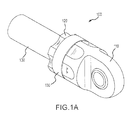
FIG. 1A illustrates a composite tube assembly, in accordance with various embodiments; -
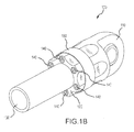
FIG. 1B illustrates a composite tube assembly, in accordance with various embodiments; -
FIG. 2A illustrates a cross-sectional view of a composite tube assembly, in accordance with various embodiments; -
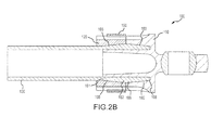
FIG. 2B illustrates a cross-sectional view of a composite tube assembly, in accordance with various embodiments; -
FIG. 2C illustrates a cross-sectional view of a composite tube assembly, in accordance with various embodiments; -
FIG. 3 illustrates a view of a composite tube assembly, in accordance with various embodiments; -
FIG. 4 illustrates a cross-sectional view of a composite tube assembly, in accordance with various embodiments; -
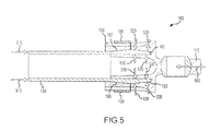
FIG. 5 illustrates a cross-sectional view of a composite tube assembly, in accordance with various embodiments; and -
FIG. 6 illustrates a method of manufacture, in accordance with various embodiments. - The detailed description of exemplary embodiments herein makes reference to the accompanying drawings, which show exemplary embodiments by way of illustration and their best mode. While these exemplary embodiments are described in sufficient detail to enable those skilled in the art to practice the disclosure, it should be understood that other embodiments may be realized and that logical, chemical, and mechanical changes may be made without departing from the scope of the disclosure. Thus, the detailed description herein is presented for purposes of illustration only and not of limitation. For example, the steps recited in any of the method or process descriptions may be executed in any order and are not necessarily limited to the order presented. Furthermore, any reference to singular includes plural embodiments, and any reference to more than one component or step may include a singular embodiment or step. Also, any reference to attached, fixed, connected or the like may include permanent, removable, temporary, partial, full and/or any other possible attachment option. Additionally, any reference to "without contact" (or similar phrases) may also include reduced contact or minimal contact.
- With reference to
FIG. 1A, FIG. 1A illustratescomposite tube assembly 100, in accordance with various embodiments.Composite tube assembly 100 may comprise acomposite tube 130, alocking ring 120, an end fitting 110, and aretaining ring 150 circumferentially disposed around thelocking ring 120. - According to various embodiments,
composite tube 130 may comprise lightweight polymer-matrix composite ("PMC") materials to utilize the anisotropic properties of the PMC material. As used herein, PMC materials may include carbon-fiber-reinforced polymers, such as carbon-fiber-reinforced plastics and carbon-fiber reinforced thermoplastics, whether now known or hereinafter developed. As used herein, the term "carbon-fiber-reinforced polymer" may include any now known or hereinafter developed material that comprises a fibrous material network (such as a network of carbon fiber) and a polymer, such as graphite epoxy. According to various embodiments, the PMC material may comprise any now known or hereinafter developed fibers. For example, in various embodiments, PMC materials may comprise aramid fibers and/or para-aramid, such as Kevlar®, a registered mark of the E. I. Du Pont de Nemours and Company, Nomex®, also a registered mark of the E. I. Du Pont de Nemours and Company, and Technora®, a registered mark of the Teijin Corporation. - According to various embodiments, the
end fitting 110 is not particularly limited. According to various embodiments, the end fitting 110 may comprise at least one of a clevis, a single bearing lug, and other known or hereinafter developed geometries for end fittings. In various embodiments, theend fitting 110 may comprise various materials, for example, a metal. Exemplary metals according to various embodiments include at least one of aluminum, tungsten, titanium, nickel, molybdenum, steel, cobalt, chromium, and alloys thereof. For example, according to various embodiments, theend fitting 110 may comprise various materials, for example steel alloys, such as high strength low alloy steel ("HSLA") that is commercially known as 300M, and/or high strength steel, such as Aermet® 100, a registered trademark of the Carpenter Technology Corporation, and/or titanium alloys, such as Ti 6Al-4V, commercially available from the Titanium Metal Corporation as Ti 6Al-4V ELI. - In various embodiments, the
locking ring 120 is not particularly limited. According to various embodiments, thelocking ring 120 may be a single integral piece or may comprise a plurality of pieces (e.g., two halves). As used herein, the term "integrated" or "integral" may include forming one, single continuous piece. In various embodiments, thelocking 120 may comprise various materials, for example, a metal. Exemplary metals according to various embodiments include at least one of aluminum, tungsten, titanium, nickel, molybdenum, steel, cobalt, chromium, and alloys thereof. For example, according to various embodiments, thelocking ring 120 may comprise various materials, for example, steel alloys, such as high strength low alloy steel ("HSLA") that is commercially known as 300M, and/or high strength steel, such as Aermet® 100, a registered trademark of the Carpenter Technology Corporation, and/or titanium alloys, such as Ti 6Al-4V, commercially available from the Titanium Metal Corporation as Ti 6Al-4V ELI. - According to various embodiments, the
retaining ring 150 is not particularly limited. In various embodiments, theretaining ring 150 may comprise various materials, for example, a PMC material and/or a metal. According to various embodiments, the PMC material is not particularly limited and may comprise any known PMC material (e.g., graphite epoxy) or any PMC material hereinafter developed. In various embodiments, the PMC material may comprise aramid fibers and/or para-aramid fibers, such as Kevlar®, a registered mark of the E. I. Du Pont de Nemours and Company, Nomex®, also a registered mark of the E. I. Du Pont de Nemours and Company, and Technora®, a registered mark of the Teijin Corporation. Exemplary metals according to various embodiments include at least one of aluminum, tungsten, titanium, nickel, molybdenum, steel, cobalt, chromium, and alloys thereof. For example, according to various embodiments, theretaining ring 150 may comprise various materials, for example, steel alloys, such as high strength low alloy steel ("HSLA") that is commercially known as 300M, and/or high strength steel, such as Aermet® 100, a registered trademark of the Carpenter Technology Corporation, and/or titanium alloys, such as Ti 6Al-4V, commercially available from the Titanium Metal Corporation as Ti 6Al-4V ELI. - With reference to
FIG. 1B, 1B illustratescomposite tube assembly 100, in accordance with various embodiments. As can be seen inFIG. 1B , according to various embodiments ofcomposite tube assembly 100, lockingring 120 may be coupled to the end fitting 110. In various embodiments, end fitting 110 may be coupled to thelocking ring 120 withretention bolts 140. As previously described, lockingring 120 is not particularly limited and may be formed as an integral piece or may comprise a plurality of pieces. Accordingly, in various embodiments, retainingring 150 may be circumferentially disposed around thelocking ring 120. - With reference to
FIGs. 2A and2B ,FIGs. 2A and2B illustrate various cross-sectionals view ofcomposite tube assembly 100, in accordance with various embodiments. As can be seen inFIGs. 2A and2B ,composite tube assembly 100 may comprise acomposite tube 130 comprising a distal end having a firstconical section 165 and a secondconical section 160. According to various embodiments, adistal end 162 of the firstconical section 165 may be in contact with aproximal end 166 of the secondconical section 160. In various embodiments, and as illustrated inFIG. 2B , theproximal end 166 of the secondconical section 160 may have the same size outer diameter as thedistal end 162 of the firstconical section 165. According to various embodiments, aproximal end 161 of the firstconical section 165 and thedistal end 168 of the secondconical section 160 may have a smaller outer diameter than thedistal end 162 of the firstconical section 165. In various embodiments, the firstconical section 165 and the secondconical section 160 may be surface treated with any known or hereinafter developed methods of surface treatment for PMC materials (e.g., nanocoated, coated with polytetrafluoroethylene ("PTFE"), coated with a metallic thermal spray, etc.). As used herein, the term "nanocoated" is not particularly limited and may include any now known or hereinafter developed methods of coating PMC materials with nanomaterials, while the term "nanomaterials" refers to a material comprised of particles that have at least one dimension between 0.1 nm and 1000 nm. According to various embodiments, various nanocoatings may increase the resistance of thecomposite tube 130 against frictional wear, such as frictional wear from end fitting 110. - In various embodiments, the
locking ring 120 may be coupled to the end fitting 110. For example,FIG. 2A illustrates lockingring 120 coupled to the end fitting 110 viaretention bolts 140. In various embodiments, the inner surface of lockingring 120 may have an inner diameter that matches the firstconical section 165 of thecomposite tube 130. Moreover, as can be seen inFIG. 2A ,composite tube assembly 100 may comprise a retainingring 150 which may surround a portion of thelocking ring 120 according to various embodiments. According to various embodiments, lockingring 120 may comprise a tapered section configured to receive the retainingring 150. In various embodiments, retainingring 150 may help securelocking ring 120. - With temporary reference to
FIG. 2C, FIG. 2C illustratescomposite tube assembly 100 according to various embodiments. According to various embodiments,composite tube assembly 100 may comprise alocking ring 120 disposed around firstconical section 165, a retainingring 150 circumferentially disposed around thelocking ring 120, and an end fitting 110 coupled to thelocking ring 120. In various embodiments, the firstconical section 165 and secondconical section 160 ofcomposite tube 130 may comprise ametallic insert 163. In various embodiments themetallic insert 163 may be bonded to the composite tube 130 (e.g., with an adhesive). In various embodiments,metallic insert 163 may be co-molded with thecomposite tube 130. In various embodiments, themetallic insert 163 may be co-cured with thecomposite tube 130. Accordingly, in various embodiments, themetallic insert 163 may be both co-molded and co-cured with thecomposite tube 130. Various adhesives may be used to bond and/or co-cure themetallic insert 163 to thecomposite tube 130 and, thus, in various embodiments, the adhesive is not limited. For example, in various embodiments, the adhesive may include any known or hereinafter developed adhesive suitable for PMC materials, such as an epoxy adhesive. An exemplary epoxy adhesive, according to various embodiments, may include Epovex®, commercially available from Zyvex Performance Materials, Incorporated. - For example, in various embodiments the
locking ring 120 may comprise a plurality of pieces (e.g., two halves of a locking ring). For example, in various embodiments, thelocking ring 120 may comprise two pieces separately manufactured. For example, with reference toFIG. 3, FIG. 3 illustratescomposite tube assembly 100 with one half of thelocking ring 120 removed and, thus, showing both aproximal end 161 anddistal end 162 of firstconical section 165. As can be seen inFIG. 3 , lockingring 120 may be secured to end fitting 110 viaretention bolts 140. In various embodiments, retaining ring 150 (only partially shown for clarity) may be configured to hold thelocking ring 120 together. For example, in various embodiments the retainingring 150 may help to retain various axial loads that may try to separate thelocking ring 120 from firstconical section 165. - For example, with reference to
FIG. 4, FIG. 4 illustratescomposite tube assembly 100 under atensile load 400 in accordance with various embodiments. In various embodiments, at times when atensile load 400 is applied to end fitting 110 disposed around secondconical section 160, this may cause a longitudinaltensile load 430 on lockingring 120, which may be coupled to end fitting 110 (e.g., withretention bolts 140 as illustrated inFIG. 2A ). The longitudinaltensile load 430 on lockingring 120 may exert a radiallyoutward load 440 on lockingring 120 due to the configuration of end fitting 110 and the configuration of the inner diameter of lockingring 120 and the firstconical section 165 ofcomposite tube 130. As used herein, the term "radially" may include a direction primarily directed towards and/or away from a longitudinal axis of thecomposite tube 130. For example, in various embodiments a radially outward compressive force may be primarily directed away from axis A-A' and, thus, may not necessarily be orthogonal to axis A-A' shown inFIG. 4 . - However, in various embodiments, the
locking ring 120 may be held in place with the retention bolts 140 (illustrated inFIG. 2A ) and with the retainingring 150. In various embodiments, the placement of retainingring 150 may result in a radiallycompressive force 420, which, in various embodiments, may help keep lockingring 120 disposed around firstconical section 165 and coupled to end fitting 110. The continued disposition of lockingring 120 around firstconical section 165 and the continued coupling of lockingring 120 to end fitting 110 may, in various embodiments, result in a longitudinaltensile load 410 on thecomposite tube 130. In various embodiments, thecomposite tube 130 may be configured to not collapse in response to longitudinaltensile load 410 and, thus,composite tube 130 may react totensile load 400 applied to end fitting 110. - With reference to
FIG. 5, FIG. 5 illustratescomposite tube assembly 100 under acompressive load 500 in accordance with various embodiments. In various embodiments,compressive load 500 may be applied to end fitting 110, which may be coupled to lockingring 120 disposed around firstconical section 165 and circumferentially surrounded by retainingring 150. At times whencompressive load 500 is applied to end fitting 110, thecompressive load 500 may be transferred to the secondconical section 160 ofcomposite tube 130. In various embodiments, the end fitting 110 may be disposed around the secondconical section 160 located at a distal end ofcomposite tube 130 so that thecompressive load 500 may be transferred to the secondconical section 160 as an internalcompressive load 530 and an outercompressive load 520. Accordingly, in various embodiments, the internalcompressive load 530 and the outercompressive load 520 may result in longitudinalcompressive load 510 oncomposite tube 130. In various embodiments, thecomposite tube 130 may be configured to not collapse in response to longitudinalcompressive load 510 and, thus,composite tube 130 may react tocompressive load 500 applied to end fitting 110. - With reference to
FIG. 6, FIG. 6 illustratesmethod 600 of manufacturing acomposite tube assembly 100, according to various embodiments. First, a retainingring 150 may be disposed around a composite tube 130 (step 610). In various embodiments and with temporary reference toFIG. 2A , a distal end of thecomposite tube 130 may comprise a firstconical section 165 and a secondconical section 160, wherein adistal end 162 of the firstconical section 165 is in contact with aproximal end 166 of the secondconical section 160. In various embodiments, theproximal end 166 of the secondconical section 160 may have the same outer diameter as thedistal end 162 of the firstconical section 165, for example, as illustrated inFIG. 2A . According to various embodiments, aproximal end 161 of the firstconical section 165 and thedistal end 168 of the secondconical section 160 may have a smaller outer diameter than thedistal end 162 of the firstconical section 165. In various embodiments, thecomposite tube 130 may comprise ametallic insert 163, as illustrated inFIG. 2C . - With reference back to
FIG. 6 , in various embodiments,method 600 may comprise disposing an end fitting 110 around the secondconical section 160 of the composite tube 130 (step 620). According to various embodiments,method 600 may also comprise disposing alocking ring 120 around the firstconical section 165 of thecomposite tube 130 so the retainingring 150 circumferentially surrounds thelocking ring 120 disposed around the first conical section 165 (step 630). In various embodiments, thelocking ring 120 is not particularly limited. For example, in various embodiments, thelocking ring 120 may comprise a plurality of pieces (e.g., two halves). According to various embodiments, alocking ring 120 having a plurality of pieces may facilitate manufacture ofcomposite tube assembly 100. Further, in various embodiments where thelocking ring 120 comprises a plurality of pieces, the retainingring 150 may help to prevent the axial separation of thelocking ring 120 from the firstconical section 165. In various embodiments,method 600 may also comprise coupling thelocking ring 120 to the end fitting 110 (step 640). For example, in various embodiments,retention bolts 140 may be used to couple thelocking ring 120 to the end fitting 110. - Benefits, other advantages, and solutions to problems have been described herein with regard to specific embodiments. Furthermore, the connecting lines shown in the various figures contained herein are intended to represent exemplary functional relationships and/or physical couplings between the various elements. It should be noted that many alternative or additional functional relationships or physical connections may be present in a practical system. However, the benefits, advantages, solutions to problems, and any elements that may cause any benefit, advantage, or solution to occur or become more pronounced are not to be construed as critical, required, or essential features or elements of the disclosed embodiments. The scope of the claimed embodiments is accordingly to be limited by nothing other than the appended claims, in which reference to an element in the singular is not intended to mean "one and only one" unless explicitly so stated, but rather "one or more." Moreover, where a phrase similar to "at least one of A, B, or C" is used in the claims, it is intended that the phrase be interpreted to mean that A alone may be present in an embodiment, B alone may be present in an embodiment, C alone may be present in an embodiment, or that any combination of the elements A, B and C may be present in a single embodiment; for example, A and B, A and C, B and C, or A and B and C. Different cross-hatching is used throughout the figures to denote different parts but not necessarily to denote the same or different materials.
- Systems, methods and apparatus are provided herein. In the detailed description herein, references to "one embodiment", "an embodiment", "an example embodiment", etc., indicate that the embodiment described may include a particular feature, structure, or characteristic, but every embodiment may not necessarily include the particular feature, structure, or characteristic. Moreover, such phrases are not necessarily referring to the same embodiment. Further, when a particular feature, structure, or characteristic is described in connection with an embodiment, it is submitted that it is within the knowledge of one skilled in the art to affect such feature, structure, or characteristic in connection with other embodiments whether or not explicitly described. After reading the description, it will be apparent to one skilled in the relevant art(s) how to implement the disclosure in alternative embodiments.
- Furthermore, no element, component, or method step in the present disclosure is intended to be dedicated to the public regardless of whether the element, component, or method step is explicitly recited in the claims. No claim element herein is to be construed under the provisions of 35 U.S.C. § 112(f), unless the element is expressly recited using the phrase "means for." As used herein, the terms "comprises", "comprising", or any other variation thereof, are intended to cover a non-exclusive inclusion, such that a process, method, article, or apparatus that comprises a list of elements does not include only those elements but may include other elements not expressly listed or inherent to such process, method, article, or apparatus.
Claims (15)
- A composite tube assembly (100) comprising:a composite tube (130) comprising a distal end having a first conical section (165) and a second conical section (160),wherein a distal end (162) of the first conical section (165) is in contact with a proximal end (166) of the second conical section (160) having the same outer diameter as the distal end (162) of the first conical section (165),wherein a proximal end (161) of the first conical section (165) and a distal end (168) of the second conical section (160) have a smaller outer diameter than the distal end (162) of the first conical section (165);a locking ring (120) disposed around the first conical section (165);an end fitting (110) disposed around the second conical section (160),wherein the end fitting (110) is coupled to the locking ring (120); anda retaining ring (150) circumferentially disposed around the locking ring (120).
- The composite tube assembly of claim 1, wherein the end fitting (110) is coupled to the locking ring (120) with retention bolts (140).
- The composite tube assembly of claim 1 or 2, wherein the locking ring (120) comprises a plurality of pieces.
- The composite tube assembly of claim 1, 2 or 3, wherein the retaining ring (150) comprises carbon fiber.
- The composite tube assembly of any preceding claim, wherein the retaining ring (150) comprises a metal.
- The composite tube assembly of any preceding claim, wherein the first conical section (165) and the second conical section (160) are nanocoated.
- The composite tube assembly of any preceding claim, wherein the outer diameter of the distal end (168) of the second conical section (160) is the same size as the proximal end (161) of the first conical section (165).
- The composite tube assembly of any preceding claim, wherein the first conical section (165) and the second conical section (160) comprise a metallic insert (163).
- The composite tube assembly of claim 8, wherein the metallic insert (163) is co-molded with the composite tube (130).
- The composite tube assembly of claim 8, wherein the metallic insert (163) is bonded with the composite tube (130).
- The composite tube assembly of claim 8, wherein the metallic insert (163) is co-cured with the composite tube (130).
- A method of manufacture comprising:disposing a retaining ring (150) around a composite tube (130),wherein a distal end of the composite tube (130) comprises a first conical section (165) and a second conical section (160), wherein a distal end (162) of the first conical section (165) is in contact with a proximal end (166) of the second conical section (160) having the same outer diameter as the distal end (162) of the first conical section (165),wherein a proximal end (161) of the first conical section (165) and a distal end (168) of the second conical section (160) have a smaller outer diameter than the distal end (162) of the first conical section (165);disposing an end fitting (110) around the second conical section (160);disposing a locking ring (120) around the first conical section (165) of the composite tube (130) so the retaining ring (150) circumferentially surrounds the locking ring (120) disposed around the first conical section (165); andcoupling the locking ring (120) to the end fitting (110).
- The method of claim 12, wherein the locking ring (120) is coupled to the end fitting (110) with retention bolts (140).
- The method of claim 12 or 13, wherein the composite tube (130) comprises a metallic insert (163).
- The method of claim 12, 13 or 14, wherein the locking ring (120) comprises a plurality of pieces.
Applications Claiming Priority (1)
| Application Number | Priority Date | Filing Date | Title |
|---|---|---|---|
| US14/248,140 US9441374B2 (en) | 2014-04-08 | 2014-04-08 | Struts and methods utilizing a compression collar |
Publications (2)
| Publication Number | Publication Date |
|---|---|
| EP2930377A1 true EP2930377A1 (en) | 2015-10-14 |
| EP2930377B1 EP2930377B1 (en) | 2017-03-01 |
Family
ID=52813933
Family Applications (1)
| Application Number | Title | Priority Date | Filing Date |
|---|---|---|---|
| EP15161315.5A Active EP2930377B1 (en) | 2014-04-08 | 2015-03-27 | Struts and methods utilizing a compression collar |
Country Status (2)
| Country | Link |
|---|---|
| US (2) | US9441374B2 (en) |
| EP (1) | EP2930377B1 (en) |
Cited By (1)
| Publication number | Priority date | Publication date | Assignee | Title |
|---|---|---|---|---|
| US10527086B2 (en) | 2017-06-30 | 2020-01-07 | Crompton Technology Group Limited | Strut comprising composite cylinder with a mid-strut fitting |
Families Citing this family (12)
| Publication number | Priority date | Publication date | Assignee | Title |
|---|---|---|---|---|
| US9441374B2 (en) | 2014-04-08 | 2016-09-13 | Goodrich Corporation | Struts and methods utilizing a compression collar |
| EP3025846B1 (en) * | 2014-11-28 | 2019-11-13 | Crompton Technology Group Limited | Composite tension/compression strut |
| US10066649B2 (en) | 2015-10-13 | 2018-09-04 | Goodrich Corporation | Hybrid metallic/composite piston head joint |
| EP3203094B1 (en) * | 2016-02-04 | 2021-09-22 | Crompton Technology Group Limited | Composite shaft joint |
| US10532518B2 (en) * | 2016-10-05 | 2020-01-14 | Goodrich Corporation | Hybrid metallic/composite joint with enhanced performance |
| US10927883B2 (en) * | 2017-07-11 | 2021-02-23 | Goodrich Corporation | Composite joint assembly |
| US11407014B2 (en) | 2017-10-25 | 2022-08-09 | Gregory Lee Newth | Duct-cleaning device and method |
| US11156245B2 (en) | 2018-01-08 | 2021-10-26 | Goodrich Corporation | Hybrid metallic/composite axial tension/compression lobe joint |
| US10823213B2 (en) * | 2018-06-08 | 2020-11-03 | Goodrich Corporation | Composite joint assembly |
| EP3611390B1 (en) * | 2018-08-16 | 2020-12-23 | Crompton Technology Group Limited | Composite structure having a tapered joint and a method for making the same |
| JP7148333B2 (en) | 2018-09-07 | 2022-10-05 | ナブテスコ株式会社 | Bonding of fiber-containing composites |
| US11473699B2 (en) * | 2020-06-26 | 2022-10-18 | Biolytic Lab Performance, Inc | Tubing support system |
Citations (4)
| Publication number | Priority date | Publication date | Assignee | Title |
|---|---|---|---|---|
| GB898085A (en) * | 1958-12-23 | 1962-06-06 | B C M Plastic Developments Ltd | Method of producing tubes of reinforced thermo-setting plastic material |
| US5318374A (en) * | 1992-09-23 | 1994-06-07 | The Boeing Company | Composite tube structure |
| US20010001769A1 (en) * | 1993-11-30 | 2001-05-24 | Yukitane Kimoto | Propeller shaft |
| GB2454958A (en) * | 2007-11-23 | 2009-05-27 | Crompton Technology Group Ltd | A connector for a composite tubular shaft |
Family Cites Families (24)
| Publication number | Priority date | Publication date | Assignee | Title |
|---|---|---|---|---|
| US756350A (en) * | 1901-10-26 | 1904-04-05 | Frank A Garbutt | Hose-mender. |
| US2284982A (en) * | 1941-12-31 | 1942-06-02 | Agatha Dietz Palmer | Safety machine tool coupling |
| US3560028A (en) * | 1968-01-19 | 1971-02-02 | Mitsui Petrochemical Ind | Pipe joint device |
| US3999354A (en) * | 1975-07-31 | 1976-12-28 | Alcan Aluminum Corporation | Structural member and box beam employing same |
| US4792320A (en) * | 1985-09-18 | 1988-12-20 | A. O. Smith Corporation | Composite tubular structure |
| US4810010A (en) * | 1986-02-18 | 1989-03-07 | Vetco Gray Inc. | Composite tubing connector assembly |
| US4790569A (en) * | 1987-01-12 | 1988-12-13 | The Gates Rubber Company | Reverse taper ring lock coupler and method |
| US5868435A (en) * | 1987-06-23 | 1999-02-09 | Proprietary Technology, Inc. | Apparatus for and method of attaching conduits to a fitting |
| FR2637952B1 (en) | 1988-10-13 | 1991-01-04 | Aerospatiale | DEVICE FOR CONNECTING THE END OF A COMPOSITE TUBE HIGHLY AXILICALLY SOLICITED WITH METAL FLANGES AND ITS MANUFACTURING METHOD |
| FR2641841B1 (en) * | 1988-12-29 | 1991-05-10 | Aerospatiale | PROCESS FOR INTEGRATING A METAL END PIECE IN A TUBE MADE OF COMPOSITE COIL MATERIAL AND TUBE THUS PRODUCED |
| US4930204A (en) * | 1989-02-01 | 1990-06-05 | A. O. Smith Corporation | Method of forming composite tubular structure |
| US6042152A (en) * | 1997-10-01 | 2000-03-28 | Technical Products Group, Inc. | Interface system between composite tubing and end fittings |
| US5956836A (en) * | 1998-05-04 | 1999-09-28 | General Motors Corporation | Method of making a torsional damper |
| US6282791B1 (en) * | 1999-08-26 | 2001-09-04 | Asc Incorporated | Method of making an automotive vehicle convertible roof |
| CA2481730C (en) | 2002-04-19 | 2010-03-23 | Bell Helicopter Textron Inc. | Composite drive shaft with captured end adapters |
| US7354354B2 (en) * | 2004-12-17 | 2008-04-08 | Integran Technologies Inc. | Article comprising a fine-grained metallic material and a polymeric material |
| US7943218B2 (en) * | 2006-08-14 | 2011-05-17 | Frito-Lay North America, Inc. | Environmentally-friendly multi-layer flexible film having barrier properties |
| US8205315B2 (en) * | 2006-11-01 | 2012-06-26 | Tyee Aircraft | Composite tube assemblies and methods of forming the same |
| US7452156B2 (en) * | 2006-11-17 | 2008-11-18 | The Boeing Company | Composite structural member and method for making the same |
| US8157469B2 (en) * | 2006-11-22 | 2012-04-17 | The Boeing Company | Composite structural member and method for producing the same |
| US8414724B2 (en) * | 2006-12-02 | 2013-04-09 | The Boeing Company | Composite tube having cobonded end fittings and method of making same |
| US7708610B1 (en) * | 2007-02-15 | 2010-05-04 | Richard Horan | Rowing oar system with articulating handle |
| US8161619B2 (en) | 2007-11-02 | 2012-04-24 | The Boeing Company | Joint for hybrid composite items |
| US9441374B2 (en) | 2014-04-08 | 2016-09-13 | Goodrich Corporation | Struts and methods utilizing a compression collar |
-
2014
- 2014-04-08 US US14/248,140 patent/US9441374B2/en active Active
-
2015
- 2015-03-27 EP EP15161315.5A patent/EP2930377B1/en active Active
-
2016
- 2016-08-09 US US15/232,381 patent/US10233644B2/en active Active
Patent Citations (4)
| Publication number | Priority date | Publication date | Assignee | Title |
|---|---|---|---|---|
| GB898085A (en) * | 1958-12-23 | 1962-06-06 | B C M Plastic Developments Ltd | Method of producing tubes of reinforced thermo-setting plastic material |
| US5318374A (en) * | 1992-09-23 | 1994-06-07 | The Boeing Company | Composite tube structure |
| US20010001769A1 (en) * | 1993-11-30 | 2001-05-24 | Yukitane Kimoto | Propeller shaft |
| GB2454958A (en) * | 2007-11-23 | 2009-05-27 | Crompton Technology Group Ltd | A connector for a composite tubular shaft |
Cited By (1)
| Publication number | Priority date | Publication date | Assignee | Title |
|---|---|---|---|---|
| US10527086B2 (en) | 2017-06-30 | 2020-01-07 | Crompton Technology Group Limited | Strut comprising composite cylinder with a mid-strut fitting |
Also Published As
| Publication number | Publication date |
|---|---|
| US9441374B2 (en) | 2016-09-13 |
| EP2930377B1 (en) | 2017-03-01 |
| US20150284957A1 (en) | 2015-10-08 |
| US10233644B2 (en) | 2019-03-19 |
| US20160348370A1 (en) | 2016-12-01 |
Similar Documents
| Publication | Publication Date | Title |
|---|---|---|
| EP2930377B1 (en) | Struts and methods utilizing a compression collar | |
| US10288101B2 (en) | Struts and methods utilizing a locking collar nut | |
| US9726325B2 (en) | Composite tube assemblies and methods | |
| US10539174B2 (en) | Composite joint assembly | |
| US11067114B2 (en) | Composite end connections | |
| US10066649B2 (en) | Hybrid metallic/composite piston head joint | |
| EP3427927B1 (en) | Composite joint assembly | |
| US20220025923A1 (en) | Transmission shaft | |
| US12092137B2 (en) | Hybrid metallic/composite joint with enhanced strength | |
| US10272991B2 (en) | Metallic composite joint | |
| US11519454B2 (en) | Hybrid metallic/composite tube design to transfer bending, axial, and flexural shear | |
| EP3263448B1 (en) | Manufacturing method of polymer composite/metal load transfer joint for landing gear | |
| US11378215B2 (en) | Apparatus for duct connection |
Legal Events
| Date | Code | Title | Description |
|---|---|---|---|
| PUAI | Public reference made under article 153(3) epc to a published international application that has entered the european phase |
Free format text: ORIGINAL CODE: 0009012 |
|
| AK | Designated contracting states |
Kind code of ref document: A1 Designated state(s): AL AT BE BG CH CY CZ DE DK EE ES FI FR GB GR HR HU IE IS IT LI LT LU LV MC MK MT NL NO PL PT RO RS SE SI SK SM TR |
|
| AX | Request for extension of the european patent |
Extension state: BA ME |
|
| 17P | Request for examination filed |
Effective date: 20160413 |
|
| RBV | Designated contracting states (corrected) |
Designated state(s): AL AT BE BG CH CY CZ DE DK EE ES FI FR GB GR HR HU IE IS IT LI LT LU LV MC MK MT NL NO PL PT RO RS SE SI SK SM TR |
|
| GRAP | Despatch of communication of intention to grant a patent |
Free format text: ORIGINAL CODE: EPIDOSNIGR1 |
|
| INTG | Intention to grant announced |
Effective date: 20160921 |
|
| RAP1 | Party data changed (applicant data changed or rights of an application transferred) |
Owner name: GOODRICH CORPORATION |
|
| GRAS | Grant fee paid |
Free format text: ORIGINAL CODE: EPIDOSNIGR3 |
|
| GRAA | (expected) grant |
Free format text: ORIGINAL CODE: 0009210 |
|
| AK | Designated contracting states |
Kind code of ref document: B1 Designated state(s): AL AT BE BG CH CY CZ DE DK EE ES FI FR GB GR HR HU IE IS IT LI LT LU LV MC MK MT NL NO PL PT RO RS SE SI SK SM TR |
|
| REG | Reference to a national code |
Ref country code: GB Ref legal event code: FG4D |
|
| REG | Reference to a national code |
Ref country code: CH Ref legal event code: EP Ref country code: AT Ref legal event code: REF Ref document number: 871722 Country of ref document: AT Kind code of ref document: T Effective date: 20170315 |
|
| REG | Reference to a national code |
Ref country code: IE Ref legal event code: FG4D Ref country code: FR Ref legal event code: PLFP Year of fee payment: 3 |
|
| REG | Reference to a national code |
Ref country code: DE Ref legal event code: R096 Ref document number: 602015001596 Country of ref document: DE |
|
| REG | Reference to a national code |
Ref country code: NL Ref legal event code: MP Effective date: 20170301 |
|
| REG | Reference to a national code |
Ref country code: LT Ref legal event code: MG4D |
|
| REG | Reference to a national code |
Ref country code: AT Ref legal event code: MK05 Ref document number: 871722 Country of ref document: AT Kind code of ref document: T Effective date: 20170301 |
|
| PG25 | Lapsed in a contracting state [announced via postgrant information from national office to epo] |
Ref country code: GR Free format text: LAPSE BECAUSE OF FAILURE TO SUBMIT A TRANSLATION OF THE DESCRIPTION OR TO PAY THE FEE WITHIN THE PRESCRIBED TIME-LIMIT Effective date: 20170602 Ref country code: HR Free format text: LAPSE BECAUSE OF FAILURE TO SUBMIT A TRANSLATION OF THE DESCRIPTION OR TO PAY THE FEE WITHIN THE PRESCRIBED TIME-LIMIT Effective date: 20170301 Ref country code: FI Free format text: LAPSE BECAUSE OF FAILURE TO SUBMIT A TRANSLATION OF THE DESCRIPTION OR TO PAY THE FEE WITHIN THE PRESCRIBED TIME-LIMIT Effective date: 20170301 Ref country code: NO Free format text: LAPSE BECAUSE OF FAILURE TO SUBMIT A TRANSLATION OF THE DESCRIPTION OR TO PAY THE FEE WITHIN THE PRESCRIBED TIME-LIMIT Effective date: 20170601 Ref country code: LT Free format text: LAPSE BECAUSE OF FAILURE TO SUBMIT A TRANSLATION OF THE DESCRIPTION OR TO PAY THE FEE WITHIN THE PRESCRIBED TIME-LIMIT Effective date: 20170301 |
|
| PG25 | Lapsed in a contracting state [announced via postgrant information from national office to epo] |
Ref country code: LV Free format text: LAPSE BECAUSE OF FAILURE TO SUBMIT A TRANSLATION OF THE DESCRIPTION OR TO PAY THE FEE WITHIN THE PRESCRIBED TIME-LIMIT Effective date: 20170301 Ref country code: ES Free format text: LAPSE BECAUSE OF FAILURE TO SUBMIT A TRANSLATION OF THE DESCRIPTION OR TO PAY THE FEE WITHIN THE PRESCRIBED TIME-LIMIT Effective date: 20170301 Ref country code: BG Free format text: LAPSE BECAUSE OF FAILURE TO SUBMIT A TRANSLATION OF THE DESCRIPTION OR TO PAY THE FEE WITHIN THE PRESCRIBED TIME-LIMIT Effective date: 20170601 Ref country code: SE Free format text: LAPSE BECAUSE OF FAILURE TO SUBMIT A TRANSLATION OF THE DESCRIPTION OR TO PAY THE FEE WITHIN THE PRESCRIBED TIME-LIMIT Effective date: 20170301 Ref country code: RS Free format text: LAPSE BECAUSE OF FAILURE TO SUBMIT A TRANSLATION OF THE DESCRIPTION OR TO PAY THE FEE WITHIN THE PRESCRIBED TIME-LIMIT Effective date: 20170301 Ref country code: AT Free format text: LAPSE BECAUSE OF FAILURE TO SUBMIT A TRANSLATION OF THE DESCRIPTION OR TO PAY THE FEE WITHIN THE PRESCRIBED TIME-LIMIT Effective date: 20170301 |
|
| PG25 | Lapsed in a contracting state [announced via postgrant information from national office to epo] |
Ref country code: NL Free format text: LAPSE BECAUSE OF FAILURE TO SUBMIT A TRANSLATION OF THE DESCRIPTION OR TO PAY THE FEE WITHIN THE PRESCRIBED TIME-LIMIT Effective date: 20170301 |
|
| REG | Reference to a national code |
Ref country code: DE Ref legal event code: R119 Ref document number: 602015001596 Country of ref document: DE |
|
| PG25 | Lapsed in a contracting state [announced via postgrant information from national office to epo] |
Ref country code: RO Free format text: LAPSE BECAUSE OF FAILURE TO SUBMIT A TRANSLATION OF THE DESCRIPTION OR TO PAY THE FEE WITHIN THE PRESCRIBED TIME-LIMIT Effective date: 20170301 Ref country code: IT Free format text: LAPSE BECAUSE OF FAILURE TO SUBMIT A TRANSLATION OF THE DESCRIPTION OR TO PAY THE FEE WITHIN THE PRESCRIBED TIME-LIMIT Effective date: 20170301 Ref country code: SK Free format text: LAPSE BECAUSE OF FAILURE TO SUBMIT A TRANSLATION OF THE DESCRIPTION OR TO PAY THE FEE WITHIN THE PRESCRIBED TIME-LIMIT Effective date: 20170301 Ref country code: CZ Free format text: LAPSE BECAUSE OF FAILURE TO SUBMIT A TRANSLATION OF THE DESCRIPTION OR TO PAY THE FEE WITHIN THE PRESCRIBED TIME-LIMIT Effective date: 20170301 Ref country code: EE Free format text: LAPSE BECAUSE OF FAILURE TO SUBMIT A TRANSLATION OF THE DESCRIPTION OR TO PAY THE FEE WITHIN THE PRESCRIBED TIME-LIMIT Effective date: 20170301 |
|
| PG25 | Lapsed in a contracting state [announced via postgrant information from national office to epo] |
Ref country code: PL Free format text: LAPSE BECAUSE OF FAILURE TO SUBMIT A TRANSLATION OF THE DESCRIPTION OR TO PAY THE FEE WITHIN THE PRESCRIBED TIME-LIMIT Effective date: 20170301 Ref country code: PT Free format text: LAPSE BECAUSE OF FAILURE TO SUBMIT A TRANSLATION OF THE DESCRIPTION OR TO PAY THE FEE WITHIN THE PRESCRIBED TIME-LIMIT Effective date: 20170703 Ref country code: SM Free format text: LAPSE BECAUSE OF FAILURE TO SUBMIT A TRANSLATION OF THE DESCRIPTION OR TO PAY THE FEE WITHIN THE PRESCRIBED TIME-LIMIT Effective date: 20170301 Ref country code: IS Free format text: LAPSE BECAUSE OF FAILURE TO SUBMIT A TRANSLATION OF THE DESCRIPTION OR TO PAY THE FEE WITHIN THE PRESCRIBED TIME-LIMIT Effective date: 20170701 |
|
| REG | Reference to a national code |
Ref country code: IE Ref legal event code: MM4A |
|
| PLBE | No opposition filed within time limit |
Free format text: ORIGINAL CODE: 0009261 |
|
| STAA | Information on the status of an ep patent application or granted ep patent |
Free format text: STATUS: NO OPPOSITION FILED WITHIN TIME LIMIT |
|
| PG25 | Lapsed in a contracting state [announced via postgrant information from national office to epo] |
Ref country code: DE Free format text: LAPSE BECAUSE OF NON-PAYMENT OF DUE FEES Effective date: 20171003 Ref country code: MC Free format text: LAPSE BECAUSE OF FAILURE TO SUBMIT A TRANSLATION OF THE DESCRIPTION OR TO PAY THE FEE WITHIN THE PRESCRIBED TIME-LIMIT Effective date: 20170301 Ref country code: DK Free format text: LAPSE BECAUSE OF FAILURE TO SUBMIT A TRANSLATION OF THE DESCRIPTION OR TO PAY THE FEE WITHIN THE PRESCRIBED TIME-LIMIT Effective date: 20170301 Ref country code: LU Free format text: LAPSE BECAUSE OF NON-PAYMENT OF DUE FEES Effective date: 20170327 |
|
| 26N | No opposition filed |
Effective date: 20171204 |
|
| REG | Reference to a national code |
Ref country code: FR Ref legal event code: PLFP Year of fee payment: 4 |
|
| PG25 | Lapsed in a contracting state [announced via postgrant information from national office to epo] |
Ref country code: SI Free format text: LAPSE BECAUSE OF FAILURE TO SUBMIT A TRANSLATION OF THE DESCRIPTION OR TO PAY THE FEE WITHIN THE PRESCRIBED TIME-LIMIT Effective date: 20170301 Ref country code: IE Free format text: LAPSE BECAUSE OF NON-PAYMENT OF DUE FEES Effective date: 20170327 |
|
| REG | Reference to a national code |
Ref country code: BE Ref legal event code: MM Effective date: 20170331 |
|
| PG25 | Lapsed in a contracting state [announced via postgrant information from national office to epo] |
Ref country code: BE Free format text: LAPSE BECAUSE OF NON-PAYMENT OF DUE FEES Effective date: 20170331 |
|
| PG25 | Lapsed in a contracting state [announced via postgrant information from national office to epo] |
Ref country code: MT Free format text: LAPSE BECAUSE OF NON-PAYMENT OF DUE FEES Effective date: 20170327 |
|
| REG | Reference to a national code |
Ref country code: CH Ref legal event code: PL |
|
| PG25 | Lapsed in a contracting state [announced via postgrant information from national office to epo] |
Ref country code: CH Free format text: LAPSE BECAUSE OF NON-PAYMENT OF DUE FEES Effective date: 20180331 Ref country code: LI Free format text: LAPSE BECAUSE OF NON-PAYMENT OF DUE FEES Effective date: 20180331 |
|
| PG25 | Lapsed in a contracting state [announced via postgrant information from national office to epo] |
Ref country code: HU Free format text: LAPSE BECAUSE OF FAILURE TO SUBMIT A TRANSLATION OF THE DESCRIPTION OR TO PAY THE FEE WITHIN THE PRESCRIBED TIME-LIMIT; INVALID AB INITIO Effective date: 20150327 |
|
| PG25 | Lapsed in a contracting state [announced via postgrant information from national office to epo] |
Ref country code: CY Free format text: LAPSE BECAUSE OF FAILURE TO SUBMIT A TRANSLATION OF THE DESCRIPTION OR TO PAY THE FEE WITHIN THE PRESCRIBED TIME-LIMIT Effective date: 20170301 |
|
| PG25 | Lapsed in a contracting state [announced via postgrant information from national office to epo] |
Ref country code: MK Free format text: LAPSE BECAUSE OF FAILURE TO SUBMIT A TRANSLATION OF THE DESCRIPTION OR TO PAY THE FEE WITHIN THE PRESCRIBED TIME-LIMIT Effective date: 20170301 |
|
| PG25 | Lapsed in a contracting state [announced via postgrant information from national office to epo] |
Ref country code: TR Free format text: LAPSE BECAUSE OF FAILURE TO SUBMIT A TRANSLATION OF THE DESCRIPTION OR TO PAY THE FEE WITHIN THE PRESCRIBED TIME-LIMIT Effective date: 20170301 |
|
| PG25 | Lapsed in a contracting state [announced via postgrant information from national office to epo] |
Ref country code: AL Free format text: LAPSE BECAUSE OF FAILURE TO SUBMIT A TRANSLATION OF THE DESCRIPTION OR TO PAY THE FEE WITHIN THE PRESCRIBED TIME-LIMIT Effective date: 20170301 |
|
| P01 | Opt-out of the competence of the unified patent court (upc) registered |
Effective date: 20230522 |
|
| PGFP | Annual fee paid to national office [announced via postgrant information from national office to epo] |
Ref country code: GB Payment date: 20260220 Year of fee payment: 12 |
|
| PGFP | Annual fee paid to national office [announced via postgrant information from national office to epo] |
Ref country code: FR Payment date: 20260219 Year of fee payment: 12 |