EP2930342A1 - Combustion engine having a splitted fuel admission and a respective method - Google Patents
Combustion engine having a splitted fuel admission and a respective method Download PDFInfo
- Publication number
- EP2930342A1 EP2930342A1 EP14164514.3A EP14164514A EP2930342A1 EP 2930342 A1 EP2930342 A1 EP 2930342A1 EP 14164514 A EP14164514 A EP 14164514A EP 2930342 A1 EP2930342 A1 EP 2930342A1
- Authority
- EP
- European Patent Office
- Prior art keywords
- mixture
- fuel
- combustion engine
- combustion chamber
- injector
- Prior art date
- Legal status (The legal status is an assumption and is not a legal conclusion. Google has not performed a legal analysis and makes no representation as to the accuracy of the status listed.)
- Withdrawn
Links
- 239000000446 fuel Substances 0.000 title claims abstract description 70
- 238000002485 combustion reaction Methods 0.000 title claims abstract description 48
- 238000000034 method Methods 0.000 title claims description 13
- 239000000203 mixture Substances 0.000 claims abstract description 44
- 238000002347 injection Methods 0.000 claims description 27
- 239000007924 injection Substances 0.000 claims description 27
- 230000035515 penetration Effects 0.000 claims description 7
- 239000007789 gas Substances 0.000 description 24
- 239000003570 air Substances 0.000 description 12
- VNWKTOKETHGBQD-UHFFFAOYSA-N methane Chemical compound C VNWKTOKETHGBQD-UHFFFAOYSA-N 0.000 description 10
- OKKJLVBELUTLKV-UHFFFAOYSA-N Methanol Chemical compound OC OKKJLVBELUTLKV-UHFFFAOYSA-N 0.000 description 9
- 238000010586 diagram Methods 0.000 description 7
- LFQSCWFLJHTTHZ-UHFFFAOYSA-N Ethanol Chemical compound CCO LFQSCWFLJHTTHZ-UHFFFAOYSA-N 0.000 description 6
- 239000003345 natural gas Substances 0.000 description 4
- 239000003502 gasoline Substances 0.000 description 3
- 239000007788 liquid Substances 0.000 description 3
- IJGRMHOSHXDMSA-UHFFFAOYSA-N Atomic nitrogen Chemical compound N#N IJGRMHOSHXDMSA-UHFFFAOYSA-N 0.000 description 2
- CURLTUGMZLYLDI-UHFFFAOYSA-N Carbon dioxide Chemical compound O=C=O CURLTUGMZLYLDI-UHFFFAOYSA-N 0.000 description 2
- ATUOYWHBWRKTHZ-UHFFFAOYSA-N Propane Chemical compound CCC ATUOYWHBWRKTHZ-UHFFFAOYSA-N 0.000 description 2
- 238000013461 design Methods 0.000 description 2
- 230000000694 effects Effects 0.000 description 2
- 239000003344 environmental pollutant Substances 0.000 description 2
- 238000002474 experimental method Methods 0.000 description 2
- 231100000719 pollutant Toxicity 0.000 description 2
- UGFAIRIUMAVXCW-UHFFFAOYSA-N Carbon monoxide Chemical compound [O+]#[C-] UGFAIRIUMAVXCW-UHFFFAOYSA-N 0.000 description 1
- 238000013459 approach Methods 0.000 description 1
- 239000001273 butane Substances 0.000 description 1
- 239000001569 carbon dioxide Substances 0.000 description 1
- 229910002092 carbon dioxide Inorganic materials 0.000 description 1
- 229910002091 carbon monoxide Inorganic materials 0.000 description 1
- 239000003054 catalyst Substances 0.000 description 1
- 230000006835 compression Effects 0.000 description 1
- 238000007906 compression Methods 0.000 description 1
- 238000011217 control strategy Methods 0.000 description 1
- 238000011161 development Methods 0.000 description 1
- 230000009977 dual effect Effects 0.000 description 1
- 230000007717 exclusion Effects 0.000 description 1
- 239000001257 hydrogen Substances 0.000 description 1
- 229910052739 hydrogen Inorganic materials 0.000 description 1
- 125000004435 hydrogen atom Chemical class [H]* 0.000 description 1
- 239000000463 material Substances 0.000 description 1
- IJDNQMDRQITEOD-UHFFFAOYSA-N n-butane Chemical compound CCCC IJDNQMDRQITEOD-UHFFFAOYSA-N 0.000 description 1
- OFBQJSOFQDEBGM-UHFFFAOYSA-N n-pentane Natural products CCCCC OFBQJSOFQDEBGM-UHFFFAOYSA-N 0.000 description 1
- 229910052757 nitrogen Inorganic materials 0.000 description 1
- 230000002035 prolonged effect Effects 0.000 description 1
- 239000001294 propane Substances 0.000 description 1
- 238000004088 simulation Methods 0.000 description 1
- 238000012360 testing method Methods 0.000 description 1
Images

Classifications
-
- F—MECHANICAL ENGINEERING; LIGHTING; HEATING; WEAPONS; BLASTING
- F02—COMBUSTION ENGINES; HOT-GAS OR COMBUSTION-PRODUCT ENGINE PLANTS
- F02M—SUPPLYING COMBUSTION ENGINES IN GENERAL WITH COMBUSTIBLE MIXTURES OR CONSTITUENTS THEREOF
- F02M21/00—Apparatus for supplying engines with non-liquid fuels, e.g. gaseous fuels stored in liquid form
- F02M21/02—Apparatus for supplying engines with non-liquid fuels, e.g. gaseous fuels stored in liquid form for gaseous fuels
- F02M21/0218—Details on the gaseous fuel supply system, e.g. tanks, valves, pipes, pumps, rails, injectors or mixers
- F02M21/0248—Injectors
- F02M21/0275—Injectors for in-cylinder direct injection, e.g. injector combined with spark plug
-
- F—MECHANICAL ENGINEERING; LIGHTING; HEATING; WEAPONS; BLASTING
- F02—COMBUSTION ENGINES; HOT-GAS OR COMBUSTION-PRODUCT ENGINE PLANTS
- F02D—CONTROLLING COMBUSTION ENGINES
- F02D19/00—Controlling engines characterised by their use of non-liquid fuels, pluralities of fuels, or non-fuel substances added to the combustible mixtures
- F02D19/06—Controlling engines characterised by their use of non-liquid fuels, pluralities of fuels, or non-fuel substances added to the combustible mixtures peculiar to engines working with pluralities of fuels, e.g. alternatively with light and heavy fuel oil, other than engines indifferent to the fuel consumed
- F02D19/0639—Controlling engines characterised by their use of non-liquid fuels, pluralities of fuels, or non-fuel substances added to the combustible mixtures peculiar to engines working with pluralities of fuels, e.g. alternatively with light and heavy fuel oil, other than engines indifferent to the fuel consumed characterised by the type of fuels
- F02D19/0642—Controlling engines characterised by their use of non-liquid fuels, pluralities of fuels, or non-fuel substances added to the combustible mixtures peculiar to engines working with pluralities of fuels, e.g. alternatively with light and heavy fuel oil, other than engines indifferent to the fuel consumed characterised by the type of fuels at least one fuel being gaseous, the other fuels being gaseous or liquid at standard conditions
- F02D19/0647—Controlling engines characterised by their use of non-liquid fuels, pluralities of fuels, or non-fuel substances added to the combustible mixtures peculiar to engines working with pluralities of fuels, e.g. alternatively with light and heavy fuel oil, other than engines indifferent to the fuel consumed characterised by the type of fuels at least one fuel being gaseous, the other fuels being gaseous or liquid at standard conditions the gaseous fuel being liquefied petroleum gas [LPG], liquefied natural gas [LNG], compressed natural gas [CNG] or dimethyl ether [DME]
-
- F—MECHANICAL ENGINEERING; LIGHTING; HEATING; WEAPONS; BLASTING
- F02—COMBUSTION ENGINES; HOT-GAS OR COMBUSTION-PRODUCT ENGINE PLANTS
- F02D—CONTROLLING COMBUSTION ENGINES
- F02D19/00—Controlling engines characterised by their use of non-liquid fuels, pluralities of fuels, or non-fuel substances added to the combustible mixtures
- F02D19/06—Controlling engines characterised by their use of non-liquid fuels, pluralities of fuels, or non-fuel substances added to the combustible mixtures peculiar to engines working with pluralities of fuels, e.g. alternatively with light and heavy fuel oil, other than engines indifferent to the fuel consumed
- F02D19/0663—Details on the fuel supply system, e.g. tanks, valves, pipes, pumps, rails, injectors or mixers
- F02D19/0686—Injectors
- F02D19/0689—Injectors for in-cylinder direct injection
-
- F—MECHANICAL ENGINEERING; LIGHTING; HEATING; WEAPONS; BLASTING
- F02—COMBUSTION ENGINES; HOT-GAS OR COMBUSTION-PRODUCT ENGINE PLANTS
- F02M—SUPPLYING COMBUSTION ENGINES IN GENERAL WITH COMBUSTIBLE MIXTURES OR CONSTITUENTS THEREOF
- F02M21/00—Apparatus for supplying engines with non-liquid fuels, e.g. gaseous fuels stored in liquid form
- F02M21/02—Apparatus for supplying engines with non-liquid fuels, e.g. gaseous fuels stored in liquid form for gaseous fuels
- F02M21/0218—Details on the gaseous fuel supply system, e.g. tanks, valves, pipes, pumps, rails, injectors or mixers
- F02M21/0284—Arrangement of multiple injectors or fuel-air mixers per combustion chamber
-
- F—MECHANICAL ENGINEERING; LIGHTING; HEATING; WEAPONS; BLASTING
- F02—COMBUSTION ENGINES; HOT-GAS OR COMBUSTION-PRODUCT ENGINE PLANTS
- F02M—SUPPLYING COMBUSTION ENGINES IN GENERAL WITH COMBUSTIBLE MIXTURES OR CONSTITUENTS THEREOF
- F02M67/00—Apparatus in which fuel-injection is effected by means of high-pressure gas, the gas carrying the fuel into working cylinders of the engine, e.g. air-injection type
- F02M67/02—Apparatus in which fuel-injection is effected by means of high-pressure gas, the gas carrying the fuel into working cylinders of the engine, e.g. air-injection type the gas being compressed air, e.g. compressed in pumps
-
- F—MECHANICAL ENGINEERING; LIGHTING; HEATING; WEAPONS; BLASTING
- F02—COMBUSTION ENGINES; HOT-GAS OR COMBUSTION-PRODUCT ENGINE PLANTS
- F02M—SUPPLYING COMBUSTION ENGINES IN GENERAL WITH COMBUSTIBLE MIXTURES OR CONSTITUENTS THEREOF
- F02M2700/00—Supplying, feeding or preparing air, fuel, fuel air mixtures or auxiliary fluids for a combustion engine; Use of exhaust gas; Compressors for piston engines
-
- Y—GENERAL TAGGING OF NEW TECHNOLOGICAL DEVELOPMENTS; GENERAL TAGGING OF CROSS-SECTIONAL TECHNOLOGIES SPANNING OVER SEVERAL SECTIONS OF THE IPC; TECHNICAL SUBJECTS COVERED BY FORMER USPC CROSS-REFERENCE ART COLLECTIONS [XRACs] AND DIGESTS
- Y02—TECHNOLOGIES OR APPLICATIONS FOR MITIGATION OR ADAPTATION AGAINST CLIMATE CHANGE
- Y02T—CLIMATE CHANGE MITIGATION TECHNOLOGIES RELATED TO TRANSPORTATION
- Y02T10/00—Road transport of goods or passengers
- Y02T10/10—Internal combustion engine [ICE] based vehicles
- Y02T10/30—Use of alternative fuels, e.g. biofuels
Definitions
- the invention is related to combustion engine having a splitted fuel admission and a respective method.
- EGR exhaust gas recirculation
- Such combustion engines can be used with boosting using turbochargers, superchargers and the like.
- the use of a three-way-catalyst enables low pollutant emissions.
- exhaust gas recirculation is used, the inflammability of the mixture is deteriorated so that high-energy spark ignition systems or pilot injection systems have to be used.
- High-energy spark ignition systems have the disadvantage that the life expectancy of spark plugs is reduced. Pilot injection systems according to the state of the art most of which using a secondary diesel-like fuel injection have to be used with the disadvantage of a dual system causing logistical problems.
- JP 07-63076 A a combustion engine is known - according to the second embodiment of that document - with a gasified fuel supplied into the port and a direct injection of a small amount of natural gas towards the spark plug prior ignition.
- the main fuel is any fuel having good mixture characteristic with air and may have a low spark--ignition characteristic, preferably compressed natural gas, which is injected into the intake manifold. It should be noted that other gases like gasified gasoline, methanol, ethanol or other gases like biogas, landfill gas or synthetic gas can be used instead.
- the second fuel is any gas according to the list above.
- the measures of the invention primarily have the effect that the spark ignition efficiency is significantly increased by injecting the secondary fuel mixture directly into the direction of the spark plug.
- the combustion engine comprises control means or adjusting means for controlling or adjusting the mixture ratio of air and gas fuel and/or, of the mixture means, the amount of the mixture of the mixture means and/or the penetration length of the mixture injected by the secondary injector means.
- the amount of the mixture can be controlled or adjusted by the end of injection in respect to the phase of the cylinder movement, e.g. with a fixed start of injection or vice versa.
- the penetration length of the mixture injected by the secondary injector means can be controlled or adjusted by the injection pressure of the mixture injected. It may be advantageous when an exhaust gas recirculation connection means comprising an external gas recirculation control valve and control means for controlling said external gas recirculation control valve is used.
- One advantageous method of operating can be provided with several, at least two injection intervals for each cylinder cycle spaced by a time without injection.
- An advantageous operation mode is when the port comprises a primary fuel injector and the same gaseous fuel is used in the primary fuel injector and the secondary fuel injector.
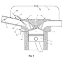
- Figure 1 shows a part of a combustion engine comprising the conventional elements like a combustion chamber (1), a piston (2) moving within a cylinder (3), a cylinder head (4) comprising an admission valve (5), an outlet valve (6) and a port (13).
- the combustion engine according to this embodiment of the invention is provided with at least one spark plug (7) for ignition.
- Fuel (12) for this internal combustion engine is mixed in the intake port (13) using a fuel injector (11) or - alternatively - another mixing device like a carburettor.
- the amount of already burned gases inside the combustion chamber (1) is controlled using external EGR (9) with an EGR control valve (10) or by setting the timing of the intake (5) and exhaust (6) gas exchange valves accordingly.
- the engine load is controlled using a throttle (8) in combination with the amount of EGR and optionally by controlling a boosting device like a turbocharger, supercharger or similar.
- fuel (12) means several liquid or gaseous fuel types.
- Typical liquid fuels are gasoline, methanol or ethanol.
- Typical gaseous fuels are natural gas, biogas, landfill gas, synthetic gas which are gases consisting mainly of methane, hydrogen, propane, butane, carbon monoxide with possible inert parts like nitrogen, carbon dioxide or air.
- a secondary fuel injector (14) which is able to inject directly into the combustion chamber (2) injects a small amount of a mixture of additional fuel (15) and air (16) prior to ignition or, if consecutive ignition is applied, prior first ignition in such a way that a good inflammable air/fuel mixture is established around the spark plug (7).
- Good inflammability can be controlled by setting the air to fuel ratio of the secondary fuel injector, the amount of the mixture as well as the penetration length of the directly injected mixture.
- the effect of the increased inflammability is not just achieved by the control of the stoichiometry of the mixture around the spark plug but also by influencing the flow field in such a way, that a fast and stable flame kernel development is given.
- secondary fuel injector which is the direct injector can be fed by a mixture of fuel and air which may be pressurized or - if not pressurized - the pressure increase of the air has to be performed within the injector.
- the secondary fuel injector may use a mixture of fuel and air mixed before.
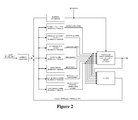
- the control of the engine system is laid out to achieve desired targets which are mainly lowest fuel consumption, lowest pollutant emissions and good driveability. This is done using feedforward and feedback control strategies on the respective actuating variables while the distribution between port fuel and direct injection (quantity, quality, timing, pressure) are new actuating variables.
- the optimum control structures are typically found by numerical modelling of the engine system and the best parameters are typically found with help of experiments on an engine test bench.
- a possible control scheme is shown in Figure 2 . This scheme allows the control of ⁇ using the port fuel- and the direct injection path by setting the injection timings, the pressures and the air/fuel ratio of the direct injection accordingly.
- port fuel injection is typically performed during the intake stroke and direct injection is performed during the compression stroke prior ignition.
- the exact phasing of the direct injection event depends on the layout of the engine and the operating point and it is typically found using numerical simulation and/or experiments.
- the typical timing diagram according to the normal mode is shown in figure 3 .
- the direct injection mode can be prolonged so that the engine can still be operated in an "emergency mode".
- the typical timing diagram according such an "emergency mode" is shown in figure 4 .
Landscapes
- Engineering & Computer Science (AREA)
- Chemical & Material Sciences (AREA)
- Combustion & Propulsion (AREA)
- Mechanical Engineering (AREA)
- General Engineering & Computer Science (AREA)
- Oil, Petroleum & Natural Gas (AREA)
- Chemical Kinetics & Catalysis (AREA)
- General Chemical & Material Sciences (AREA)
- Electrical Control Of Air Or Fuel Supplied To Internal-Combustion Engine (AREA)
- Combustion Methods Of Internal-Combustion Engines (AREA)
- Output Control And Ontrol Of Special Type Engine (AREA)
- Fuel-Injection Apparatus (AREA)
Abstract
The invention provides a combustion engine comprising at least one combustion chamber, preferably several combustion chambers (1), wherein to each combustion chamber a piston (2) moving within a cylinder (3), a cylinder head (4) comprising at least one admission valve (5), at least one outlet valve (6), at least one spark plug (7) an intake port (13) and a throttle (8) controlling the engine load, is assigned. The combustion chamber (1) comprises a secondary injector means (14) for injecting a secondary fuel directly into the combustion chamber (1) in the direction of the spark plug (7) and secondary fuel supply means (15) for supplying a gas as a secondary fuel to said secondary injector means (14). Supply means (16) for compressed air and mixture means for providing a mixture of air and gas fuel to said secondary injector means (14), facilitating the stoichiometric air-to-fuel ratio to be held at λ=1.
Description
- The invention is related to combustion engine having a splitted fuel admission and a respective method.
- Combustion engines using gaseous fuel like compressed natural gas (CNG), biogas, landfill gas or even burnable synthetic gases or gasified liquid fuels line gasoline, methanol, ethanol or the like can be operated with stoichiometric air-to-fuel ratio (λ=1) and optionally with exhaust gas recirculation (EGR). Alternatively or additionally such combustion engines can be used with boosting using turbochargers, superchargers and the like. The use of a three-way-catalyst enables low pollutant emissions. Especially when exhaust gas recirculation is used, the inflammability of the mixture is deteriorated so that high-energy spark ignition systems or pilot injection systems have to be used. High-energy spark ignition systems have the disadvantage that the life expectancy of spark plugs is reduced. Pilot injection systems according to the state of the art most of which using a secondary diesel-like fuel injection have to be used with the disadvantage of a dual system causing logistical problems.
- From
JP 07-63076 A JP 07-63076 A - According to a first aspect the invention has the object to provide a splitted gaseous fuel combustion engine enabling a stable and robust inflammability of a hard-to-ignite mixture using a spark plug together with an operation with stoichiometric air-to-fuel ratio (λ=1). According to a second aspect the invention has the object to provide an engine operation method which enables a stable and robust inflammability of a hard-to-ignite mixture using a spark plug together with stoichiometric air-to-fuel ratio (λ=1) in a split gaseous fuel combustion engine.
- The objects of the invention according to the aforementioned aspects are solved by the apparatus of
claim 1 and a method according toclaim 9, respectively. The main fuel is any fuel having good mixture characteristic with air and may have a low spark--ignition characteristic, preferably compressed natural gas, which is injected into the intake manifold. It should be noted that other gases like gasified gasoline, methanol, ethanol or other gases like biogas, landfill gas or synthetic gas can be used instead. The second fuel is any gas according to the list above. The measures of the invention primarily have the effect that the spark ignition efficiency is significantly increased by injecting the secondary fuel mixture directly into the direction of the spark plug. Moreover, the invention provides effective parameters in order to maintain the stoichiometric air-to-fuel ratio to λ=1 which parameters are the (natural) gas to air ratio of the secondary fuel mixture, the amount of secondary fuel mixture, the penetration length of the mixture injected and the injection time. - Additional controlling and/or adjusting is possible when the combustion engine comprises control means or adjusting means for controlling or adjusting the mixture ratio of air and gas fuel and/or, of the mixture means, the amount of the mixture of the mixture means and/or the penetration length of the mixture injected by the secondary injector means. The amount of the mixture can be controlled or adjusted by the end of injection in respect to the phase of the cylinder movement, e.g. with a fixed start of injection or vice versa. The penetration length of the mixture injected by the secondary injector means can be controlled or adjusted by the injection pressure of the mixture injected. It may be advantageous when an exhaust gas recirculation connection means comprising an external gas recirculation control valve and control means for controlling said external gas recirculation control valve is used.
- One advantageous method of operating can be provided with several, at least two injection intervals for each cylinder cycle spaced by a time without injection.
- In a not regular operating mode - i.e. in case of an emergency - one or more cylinders are operated by injection of the secondary injector means only.
- An advantageous operation mode is when the port comprises a primary fuel injector and the same gaseous fuel is used in the primary fuel injector and the secondary fuel injector.
- The aforementioned elements as well as those claimed and described in the following exemplary embodiments, to be used according to the invention, are not subject to any particular conditions by way of exclusion in terms of their size, shape, use of material and technical design, with the result that the selection criteria known in the respective field of application can be used without restrictions. It should be noted that all means used to implement the invention are not limited to a particular design.
- Examples of the engine will henceforth be described in more detail by reference to the drawings, wherein are shown:
- Figure 1
- is a diagram of pertinent elements of a cylinder of a combustion engine according to a preferred embodiment of the invention;
- Figure 2
- a possible control scheme for the use of the combustion engine according to
figure 1 ; - Figure 3
- a timing diagram of the fueling situation in a normal mode of the combustion engine according to
figure 1 ; - Figure 4
- a timing diagram of the fueling situation in a not regular ("emergency") mode of the combustion engine according to
figure 1 ; and - Figure 5
- a timing diagram of the fueling situation in exhaust gas increasing mode of the combustion engine according to
figure 1 . -
Figure 1 shows a part of a combustion engine comprising the conventional elements like a combustion chamber (1), a piston (2) moving within a cylinder (3), a cylinder head (4) comprising an admission valve (5), an outlet valve (6) and a port (13). The combustion engine according to this embodiment of the invention is provided with at least one spark plug (7) for ignition. - Fuel (12) for this internal combustion engine is mixed in the intake port (13) using a fuel injector (11) or - alternatively - another mixing device like a carburettor. The amount of already burned gases inside the combustion chamber (1) is controlled using external EGR (9) with an EGR control valve (10) or by setting the timing of the intake (5) and exhaust (6) gas exchange valves accordingly. The engine load is controlled using a throttle (8) in combination with the amount of EGR and optionally by controlling a boosting device like a turbocharger, supercharger or similar.
- It should be noted that fuel (12) means several liquid or gaseous fuel types. Typical liquid fuels are gasoline, methanol or ethanol. Typical gaseous fuels are natural gas, biogas, landfill gas, synthetic gas which are gases consisting mainly of methane, hydrogen, propane, butane, carbon monoxide with possible inert parts like nitrogen, carbon dioxide or air.
- In operating conditions where the inflammability of the mixtures is poor, a secondary fuel injector (14) which is able to inject directly into the combustion chamber (2) injects a small amount of a mixture of additional fuel (15) and air (16) prior to ignition or, if consecutive ignition is applied, prior first ignition in such a way that a good inflammable air/fuel mixture is established around the spark plug (7).
- The overall air-to-fuel ratio in the combustion chamber remains at λ=1. Good inflammability can be controlled by setting the air to fuel ratio of the secondary fuel injector, the amount of the mixture as well as the penetration length of the directly injected mixture. The effect of the increased inflammability is not just achieved by the control of the stoichiometry of the mixture around the spark plug but also by influencing the flow field in such a way, that a fast and stable flame kernel development is given.
- It should be noted that secondary fuel injector which is the direct injector can be fed by a mixture of fuel and air which may be pressurized or - if not pressurized - the pressure increase of the air has to be performed within the injector. Alternatively, the secondary fuel injector may use a mixture of fuel and air mixed before.
- The control of the engine system is laid out to achieve desired targets which are mainly lowest fuel consumption, lowest pollutant emissions and good driveability. This is done using feedforward and feedback control strategies on the respective actuating variables while the distribution between port fuel and direct injection (quantity, quality, timing, pressure) are new actuating variables. The optimum control structures are typically found by numerical modelling of the engine system and the best parameters are typically found with help of experiments on an engine test bench. A possible control scheme is shown in
Figure 2 . This scheme allows the control of λ using the port fuel- and the direct injection path by setting the injection timings, the pressures and the air/fuel ratio of the direct injection accordingly. - In normal mode, port fuel injection is typically performed during the intake stroke and direct injection is performed during the compression stroke prior ignition. The exact phasing of the direct injection event depends on the layout of the engine and the operating point and it is typically found using numerical simulation and/or experiments. The typical timing diagram according to the normal mode is shown in
figure 3 . - If the port fuel injector fails, the direct injection mode can be prolonged so that the engine can still be operated in an "emergency mode". The typical timing diagram according such an "emergency mode" is shown in
figure 4 . - If the exhaust gas temperature has to be increased (e.g. for thermal management reasons of the exhaust gas treatment devices), an additional direct injection event can be placed during the expansion stroke (prior opening of the exhaust valve). The typical timing diagram according such a "temperature increasing mode" is shown in
figure 5 . -
- 1
- combustion chamber
- 2
- piston
- 3
- cylinder
- 4
- cylinder head
- 5
- admission valve
- 6
- outlet valve
- 7
- spark plug
- 8
- throttle
- 9
- exhaust gas recirculation
- 10
- exhaust gas recirculation control valve
- 11
- primary fuel injector
- 12
- primary fuel supply
- 13
- port
- 14
- secondary fuel injector
- 15
- secondary fuel supply
- 16
- air supply
Claims (16)
- Combustion engine comprising at least one combustion chamber, preferably several combustion chambers (1), wherein to each combustion chamber a piston (2) moving within a cylinder (3), a cylinder head (4) comprising at least one admission valve (5), at least one outlet valve (6), at least one spark plug (7), an intake port (13) with a primary fuel injector or a carburettor and a throttle (8) controlling the engine load, is assigned, wherein said combustion chamber (1) comprises a secondary injector means (14) for injecting a secondary fuel directly into the combustion chamber (1) in the direction of the spark plug (7) and secondary fuel supply means (15) for supplying a gas as a secondary fuel to said secondary injector means (14),
characterized by
supply means (16) for pressure air and mixture means for providing a mixture of air and gas fuel to said secondary injector means (14). - Combustion engine according to claim 1, characterized by control means for controlling the mixture ratio of air and gas fuel of said mixture means.
- Combustion engine according to claim 1, characterized by adjusting means for adjusting the mixture ratio of air and gas fuel of said mixture means.
- Combustion engine according to any of claims 1 to 3, characterized by control means for controlling the amount of the mixture injected by said secondary injector means (14), preferably by controlling the end of injection.
- Combustion engine according to any of claims 1 to 3, characterized by adjusting means for adjusting the amount of the mixture injected by said secondary injector means (14), preferably by adjusting the end of injection.
- Combustion engine according to any of claims 1 to 5, characterized by control means for controlling the penetration length of the mixture injected by said secondary injector means (14), preferably by controlling the injection pressure of the mixture injected by said secondary injector means (14).
- Combustion engine according to any of claims 1 to 5, characterized by adjusting means for adjusting the penetration length of the mixture injected by said secondary injector means (14), preferably by adjusting the injection pressure of the mixture injected by said secondary injector means (14).
- Combustion engine according to any of claims 1 to 7, characterized by an exhaust gas recirculation connection means (9) comprising an external gas recirculation control valve (10) and control means for controlling said external gas recirculation control valve.
- A method for operating a combustion engine comprising at least one combustion chamber, preferably several combustion chambers (1), wherein to each combustion chamber a piston (2) moving within a cylinder (3), a cylinder head (4) comprising at least one admission valve (5), at least one outlet valve (6), at least one spark plug (7) and an intake port (13) and a throttle (8) controlling the engine load, is assigned, wherein said combustion chamber (1) comprises a secondary injector means (14) for injecting a secondary fuel directly into the combustion chamber (1) in the direction of the spark plug (7) and secondary fuel supply means (15) for supplying a gas as a secondary fuel to said secondary injector means (14),
characterized in that
pressure air is supplied and mixed with said secondary gas and provided to said secondary injector means (14) and injected. - The method according to claim 9, characterized in that the mixture is injected prior to ignition or, in case of consecutive ignitions, prior to first ignition.
- The method according to claim 9 or 10, characterized in that the mixture ratio of air and gas fuel of said mixture means is controlled by control means.
- The method according to any of claims 9 to 11, characterized in that the amount of the mixture of air and gas fuel injected by said secondary injector means (14) is controlled by control means.
- The method according to any of claims 9 to 12, characterized in that the penetration length of the mixture injected by said secondary injector means (14) is controlled by control means.
- The method according to any of claims 9 to 13, characterized by at least two injection intervals for each cylinder cycle spaced by a time wherein no injection is provided.
- The method according to any of claims 9 to 14, characterized in that the combustion engine for one or more cylinders is operated by injection of the secondary injector means (14) only.
- A method according to any of claims 9 to 15, characterized in that the port comprises a primary fuel injector and the same gaseous fuel is used in the primary fuel injector and the secondary fuel injector.
Priority Applications (5)
| Application Number | Priority Date | Filing Date | Title |
|---|---|---|---|
| EP14164514.3A EP2930342A1 (en) | 2014-04-11 | 2014-04-11 | Combustion engine having a splitted fuel admission and a respective method |
| US15/302,590 US20170022937A1 (en) | 2014-04-11 | 2015-04-10 | Internal Combustion Engine Having a Splitted Fuel Admission and a Respective Combustion Process |
| EP15714241.5A EP3129634A1 (en) | 2014-04-11 | 2015-04-10 | Internal combustion engine having a splitted fuel admission and a respective combustion process |
| PCT/EP2015/057849 WO2015155334A1 (en) | 2014-04-11 | 2015-04-10 | Internal combustion engine having a splitted fuel admission and a respective combustion process |
| JP2016561793A JP2017514060A (en) | 2014-04-11 | 2015-04-10 | Internal combustion engine with split fuel intake mechanism and individual combustion process |
Applications Claiming Priority (1)
| Application Number | Priority Date | Filing Date | Title |
|---|---|---|---|
| EP14164514.3A EP2930342A1 (en) | 2014-04-11 | 2014-04-11 | Combustion engine having a splitted fuel admission and a respective method |
Publications (1)
| Publication Number | Publication Date |
|---|---|
| EP2930342A1 true EP2930342A1 (en) | 2015-10-14 |
Family
ID=50473211
Family Applications (2)
| Application Number | Title | Priority Date | Filing Date |
|---|---|---|---|
| EP14164514.3A Withdrawn EP2930342A1 (en) | 2014-04-11 | 2014-04-11 | Combustion engine having a splitted fuel admission and a respective method |
| EP15714241.5A Withdrawn EP3129634A1 (en) | 2014-04-11 | 2015-04-10 | Internal combustion engine having a splitted fuel admission and a respective combustion process |
Family Applications After (1)
| Application Number | Title | Priority Date | Filing Date |
|---|---|---|---|
| EP15714241.5A Withdrawn EP3129634A1 (en) | 2014-04-11 | 2015-04-10 | Internal combustion engine having a splitted fuel admission and a respective combustion process |
Country Status (4)
| Country | Link |
|---|---|
| US (1) | US20170022937A1 (en) |
| EP (2) | EP2930342A1 (en) |
| JP (1) | JP2017514060A (en) |
| WO (1) | WO2015155334A1 (en) |
Cited By (1)
| Publication number | Priority date | Publication date | Assignee | Title |
|---|---|---|---|---|
| IT201800006592A1 (en) * | 2018-06-22 | 2019-12-22 | ENGINE WITH COMMANDED IGNITION WITH IMPROVED STABILITY OF OPERATION AND SPECIFIC CONSUMPTION AND METHOD OF POWER SUPPLY FOR SAID ENGINE |
Families Citing this family (1)
| Publication number | Priority date | Publication date | Assignee | Title |
|---|---|---|---|---|
| CN111305977A (en) * | 2020-02-18 | 2020-06-19 | 哈尔滨工程大学 | Hydrogen natural gas full-proportion variable dual-fuel engine |
Citations (5)
| Publication number | Priority date | Publication date | Assignee | Title |
|---|---|---|---|---|
| JPH0763076A (en) | 1993-08-24 | 1995-03-07 | Daihatsu Motor Co Ltd | Internal combustion engine |
| FR2803335A1 (en) * | 1999-12-30 | 2001-07-06 | Art & S Automotive Technology | DEVICE FOR INJECTING A FUEL INSIDE A COMBUSTION CHAMBER OF A CYLINDER OF AN INTERNAL COMBUSTION ENGINE |
| WO2001098643A2 (en) * | 2000-06-08 | 2001-12-27 | Knite, Inc. | Combustion enhancement system and method |
| EP1223321A2 (en) * | 2001-01-10 | 2002-07-17 | Hitachi, Ltd. | Internal combustion engine and fuel injection control device therefor |
| DE102010048823A1 (en) * | 2010-10-20 | 2012-04-26 | Entec Consulting Gmbh | Fuel injection system for internal-combustion engine, has cylinder head and intake device, where multiple combustion chambers are provided in cylinder head |
Family Cites Families (1)
| Publication number | Priority date | Publication date | Assignee | Title |
|---|---|---|---|---|
| US9243588B2 (en) * | 2012-09-20 | 2016-01-26 | Ford Global Technologies, Llc | Variable pressure gaseous fuel regulator |
-
2014
- 2014-04-11 EP EP14164514.3A patent/EP2930342A1/en not_active Withdrawn
-
2015
- 2015-04-10 US US15/302,590 patent/US20170022937A1/en not_active Abandoned
- 2015-04-10 EP EP15714241.5A patent/EP3129634A1/en not_active Withdrawn
- 2015-04-10 WO PCT/EP2015/057849 patent/WO2015155334A1/en not_active Ceased
- 2015-04-10 JP JP2016561793A patent/JP2017514060A/en active Pending
Patent Citations (5)
| Publication number | Priority date | Publication date | Assignee | Title |
|---|---|---|---|---|
| JPH0763076A (en) | 1993-08-24 | 1995-03-07 | Daihatsu Motor Co Ltd | Internal combustion engine |
| FR2803335A1 (en) * | 1999-12-30 | 2001-07-06 | Art & S Automotive Technology | DEVICE FOR INJECTING A FUEL INSIDE A COMBUSTION CHAMBER OF A CYLINDER OF AN INTERNAL COMBUSTION ENGINE |
| WO2001098643A2 (en) * | 2000-06-08 | 2001-12-27 | Knite, Inc. | Combustion enhancement system and method |
| EP1223321A2 (en) * | 2001-01-10 | 2002-07-17 | Hitachi, Ltd. | Internal combustion engine and fuel injection control device therefor |
| DE102010048823A1 (en) * | 2010-10-20 | 2012-04-26 | Entec Consulting Gmbh | Fuel injection system for internal-combustion engine, has cylinder head and intake device, where multiple combustion chambers are provided in cylinder head |
Cited By (2)
| Publication number | Priority date | Publication date | Assignee | Title |
|---|---|---|---|---|
| IT201800006592A1 (en) * | 2018-06-22 | 2019-12-22 | ENGINE WITH COMMANDED IGNITION WITH IMPROVED STABILITY OF OPERATION AND SPECIFIC CONSUMPTION AND METHOD OF POWER SUPPLY FOR SAID ENGINE | |
| WO2019244075A1 (en) * | 2018-06-22 | 2019-12-26 | Piaggio & C. S.P.A. | Spark ignition engine with improved operating stability and specific consumption and fueling method of said engine |
Also Published As
| Publication number | Publication date |
|---|---|
| EP3129634A1 (en) | 2017-02-15 |
| JP2017514060A (en) | 2017-06-01 |
| WO2015155334A1 (en) | 2015-10-15 |
| US20170022937A1 (en) | 2017-01-26 |
Similar Documents
| Publication | Publication Date | Title |
|---|---|---|
| US12241401B2 (en) | Internal combustion engine and a method for operating an internal combustion engine | |
| AU2017200457B2 (en) | Engine and method of operating engine | |
| US10287969B2 (en) | Internal combustion engine and method for operating an internal combustion engine | |
| CN109983213B (en) | Method and piston engine for operating a piston engine in gas mode | |
| EP2826978A1 (en) | A two-stroke internal combustion engine, method operating a two-stroke internal combustion engine and method of converting a two-stroke engine | |
| AU2013205863B2 (en) | Method for operating an engine | |
| RU2008130588A (en) | INTERNAL COMBUSTION ENGINE ON GAS FUEL AND METHOD FOR CONTROLING THE INTERNAL COMBUSTION ENGINE ON GAS FUEL | |
| US20130152900A1 (en) | Internal combustion engine | |
| US9745903B2 (en) | Dual fuel system for a combustion engine | |
| US20240191665A1 (en) | Internal combustion engine | |
| US20250354525A1 (en) | Internal combustion engine and a method for operating an internal combustion engine | |
| EP3425185B1 (en) | Spark ignition internal combustion gas engine | |
| US9016259B2 (en) | Process for controlling the combustion of an internal combustion engine with gasoline direct injection, in particular with controlled ignition | |
| JP2017155735A (en) | Crosshead type internal combustion engine | |
| EP2930342A1 (en) | Combustion engine having a splitted fuel admission and a respective method | |
| US20260063090A1 (en) | Apparatus and method for operating an internal combustion engine with multiple combustion modes | |
| CN106460715B (en) | Method of controlling a dual fuel engine | |
| Georgescu et al. | Characterisation of large gas and dual-fuel engines | |
| US20110011381A1 (en) | Internal combustion engine and method for adapting an internal combustion engine | |
| US12473870B2 (en) | Internal combustion engine and method for operating an internal combustion engine | |
| Wierzbicki et al. | Dual-fuelling compression ignition engine with methane and diesel oil. | |
| JP2019526748A (en) | Internal combustion engine operated by gas and method for operating the internal combustion engine | |
| JP2007255390A (en) | Premixed compression ignition internal combustion engine |
Legal Events
| Date | Code | Title | Description |
|---|---|---|---|
| PUAI | Public reference made under article 153(3) epc to a published international application that has entered the european phase |
Free format text: ORIGINAL CODE: 0009012 |
|
| AK | Designated contracting states |
Kind code of ref document: A1 Designated state(s): AL AT BE BG CH CY CZ DE DK EE ES FI FR GB GR HR HU IE IS IT LI LT LU LV MC MK MT NL NO PL PT RO RS SE SI SK SM TR |
|
| AX | Request for extension of the european patent |
Extension state: BA ME |
|
| STAA | Information on the status of an ep patent application or granted ep patent |
Free format text: STATUS: THE APPLICATION IS DEEMED TO BE WITHDRAWN |
|
| 18D | Application deemed to be withdrawn |
Effective date: 20160415 |