EP2930333A1 - Anti-rotational systems and methods - Google Patents
Anti-rotational systems and methods Download PDFInfo
- Publication number
- EP2930333A1 EP2930333A1 EP15163143.9A EP15163143A EP2930333A1 EP 2930333 A1 EP2930333 A1 EP 2930333A1 EP 15163143 A EP15163143 A EP 15163143A EP 2930333 A1 EP2930333 A1 EP 2930333A1
- Authority
- EP
- European Patent Office
- Prior art keywords
- pawl
- rotational system
- rotation
- contact portion
- pawl carrier
- Prior art date
- Legal status (The legal status is an assumption and is not a legal conclusion. Google has not performed a legal analysis and makes no representation as to the accuracy of the status listed.)
- Granted
Links
Images




Classifications
-
- F—MECHANICAL ENGINEERING; LIGHTING; HEATING; WEAPONS; BLASTING
- F16—ENGINEERING ELEMENTS AND UNITS; GENERAL MEASURES FOR PRODUCING AND MAINTAINING EFFECTIVE FUNCTIONING OF MACHINES OR INSTALLATIONS; THERMAL INSULATION IN GENERAL
- F16D—COUPLINGS FOR TRANSMITTING ROTATION; CLUTCHES; BRAKES
- F16D41/00—Freewheels or freewheel clutches
- F16D41/12—Freewheels or freewheel clutches with hinged pawl co-operating with teeth, cogs, or the like
-
- F—MECHANICAL ENGINEERING; LIGHTING; HEATING; WEAPONS; BLASTING
- F02—COMBUSTION ENGINES; HOT-GAS OR COMBUSTION-PRODUCT ENGINE PLANTS
- F02C—GAS-TURBINE PLANTS; AIR INTAKES FOR JET-PROPULSION PLANTS; CONTROLLING FUEL SUPPLY IN AIR-BREATHING JET-PROPULSION PLANTS
- F02C7/00—Features, components parts, details or accessories, not provided for in, or of interest apart form groups F02C1/00 - F02C6/00; Air intakes for jet-propulsion plants
- F02C7/36—Power transmission arrangements between the different shafts of the gas turbine plant, or between the gas-turbine plant and the power user
-
- F—MECHANICAL ENGINEERING; LIGHTING; HEATING; WEAPONS; BLASTING
- F16—ENGINEERING ELEMENTS AND UNITS; GENERAL MEASURES FOR PRODUCING AND MAINTAINING EFFECTIVE FUNCTIONING OF MACHINES OR INSTALLATIONS; THERMAL INSULATION IN GENERAL
- F16D—COUPLINGS FOR TRANSMITTING ROTATION; CLUTCHES; BRAKES
- F16D63/00—Brakes not otherwise provided for; Brakes combining more than one of the types of groups F16D49/00 - F16D61/00
- F16D63/006—Positive locking brakes
-
- F—MECHANICAL ENGINEERING; LIGHTING; HEATING; WEAPONS; BLASTING
- F05—INDEXING SCHEMES RELATING TO ENGINES OR PUMPS IN VARIOUS SUBCLASSES OF CLASSES F01-F04
- F05D—INDEXING SCHEME FOR ASPECTS RELATING TO NON-POSITIVE-DISPLACEMENT MACHINES OR ENGINES, GAS-TURBINES OR JET-PROPULSION PLANTS
- F05D2260/00—Function
- F05D2260/40—Transmission of power
Definitions
- the present disclosure relates to anti-rotational systems and methods, and more specifically, to anti-rotational systems and methods applicable to turbine engines.
- Turbine engines typically windmill when idle.
- a turbine engine will often windmill due to wind blowing through the engine. Many times, wind enters through the engine outlet, causing the engine to windmill in reverse.
- Many turbine engines do not have a feature to prevent the reverse wind milling of the engine or utilize a complex and/or heavy system to accomplish this feature.
- forward wind milling is often desired, for example, to enable the engine to more readily restart in flight.
- Reverse wind milling is not desired, for example, to reduce wear on the engine when idle.
- a turbine engine typically has a system to facilitate lubrication of rotating components when idle, but often this system only lubricates the rotating components when the engine is forward wind milling. Thus, reverse wind milling is often not desired.
- An anti-rotational system comprising a pawl carrier mounted for rotation within a ratchet, the pawl carrier having an axis of rotation, a pawl pivotably mounted to the pawl carrier on a pivot joint, the pawl having a contact portion and a counterweight portion, wherein the pivot joint is between the contact portion and the counterweight portion, wherein the counterweight portion is configured to be radially inward of the contact portion in response to rotation of the pawl carrier in a first rotational direction at an angular velocity less than a predetermined angular velocity.
- the counterweight portion is configured to be radially outward of the contact portion in response to rotation of the pawl carrier at an angular velocity greater than a predetermined angular velocity.
- a center of mass of the pawl is located more proximate the counterweight portion than the contact portion.
- the pawl is comprised of at least one of stainless steel and a chromium-nickel-tungsten martensitic alloy.
- the ratchet comprises a ratchet tooth.
- the pawl carrier and ratchet are mounted to rotate coaxially.
- the contact portion is configured to contact the ratchet tooth in response to rotation of the pawl carrier in a second rotational direction.
- a second pawl is pivotably mounted to the pawl carrier and a third pawl is pivotably mounted to the pawl carrier.
- the pawl, the second pawl and the third pawl are spaced 120 degrees apart on the pawl carrier.
- the ratchet has a variable radius.
- the predetermined angular velocity is between about 500rpm and 1500rpm.
- the interaction between the contact portion and the ratchet tooth prevent rotation of the pawl carrier in the second rotational direction.
- the pivot joint is at least one of lubricated and plated.
- a torsion spring is disposed proximate the pivot joint and configured to exert an outward radial force on the contact portion of the pawl.
- a stop pin disposed on the pawl carrier.
- the pawl comprises a cutout portion. In various embodiments, in response to the rotation of the pawl carrier in the first rotational direction at the angular velocity greater than the predetermined angular velocity, the counterweight portion extends radially outward of the contact portion.
- the contact portion in response to the rotation of the pawl carrier in the first rotational direction at the angular velocity less than the predetermined angular velocity, the contact portion extends radially outward of the counterweight portion. In various embodiments, in response to the rotating a pawl carrier in the second rotational direction, the contact portion of the pawl engages a ratchet tooth of the ratchet.
- any reference to singular includes plural embodiments, and any reference to more than one component or step may include a singular embodiment or step.
- any reference to attached, fixed, connected or the like may include permanent, removable, temporary, partial, full and/or any other possible attachment option.
- any reference to without contact (or similar phrases) may also include reduced contact or minimal contact.
- phrases such as “make contact with,” “coupled to,” “touch,” “interface with” and “engage” may be used interchangeably.
- tail refers to the direction associated with the tail (e.g., the back end) of an aircraft, or generally, to the direction of exhaust of the gas turbine engine.
- forward refers to the direction associated with the nose (e.g., the front end) of an aircraft, or generally, to the direction of flight or motion.
- Gas turbine engine 20 may be a two-spool turbofan that generally incorporates a fan section 22, a compressor section 24, a combustor section 26 and a turbine section 28.
- Alternative engines may include, for example, an augmentor section among other systems or features.
- fan section 22 can drive air along a bypass flow-path B while compressor section 24 can drive air along a core flow-path C for compression and communication into combustor section 26 then expansion through turbine section 28.
- turbofan gas turbine engine 20 depicted as a turbofan gas turbine engine 20 herein, it should be understood that the concepts described herein are not limited to use with turbofans as the teachings may be applied to other types of turbine engines including three-spool architectures.
- Gas turbine engine 20 may generally comprise a low speed spool 30 and a high speed spool 32 mounted for rotation about an engine central longitudinal axis A-A' relative to an engine static structure 36 via several bearing systems 38, 38-1, and 38-2. It should be understood that various bearing systems 38 at various locations may alternatively or additionally be provided, including for example, bearing system 38, bearing system 38-1, and bearing system 38-2.
- Low speed spool 30 may generally comprise an inner shaft 40 that interconnects a fan 42, a low pressure (or first) compressor section 44 and a low pressure (or first) turbine section 46.
- Inner shaft 40 may be connected to fan 42 through a geared architecture 48 that can drive fan 42 at a lower speed than low speed spool 30.
- Geared architecture 48 may comprise a gear assembly 60 enclosed within a gear housing 62.
- Gear assembly 60 couples inner shaft 40 to a rotating fan structure.
- High speed spool 32 may comprise an outer shaft 50 that interconnects a high pressure (or second) compressor section 52 and high pressure (or second) turbine section 54.
- a combustor 56 may be located between high pressure compressor 52 and high pressure turbine 54.
- a mid-turbine frame 57 of engine static structure 36 may be located generally between high pressure turbine 54 and low pressure turbine 46.
- Mid-turbine frame 57 may support one or more bearing systems 38 in turbine section 28.
- Inner shaft 40 and outer shaft 50 may be concentric and rotate via bearing systems 38 about the engine central longitudinal axis A-A', which is collinear with their longitudinal axes.
- a "high pressure" compressor or turbine experiences a higher pressure than a corresponding "low pressure” compressor or turbine.
- the core airflow C may be compressed by low pressure compressor section 44 then high pressure compressor 52, mixed and burned with fuel in combustor 56, then expanded over high pressure turbine 54 and low pressure turbine 46.
- Mid-turbine frame 57 includes airfoils 59 which are in the core airflow path. Turbines 46, 54 rotationally drive the respective low speed spool 30 and high speed spool 32 in response to the expansion.
- Gas turbine engine 20 may be, for example, a high-bypass geared aircraft engine.
- geared architecture 48 may be an epicyclic gear train, such as a star gear system (sun gear in meshing engagement with a plurality of star gears supported by a carrier and in meshing engagement with a ring gear) or other gear system.
- Gear architecture 48 may have a gear reduction ratio of greater than about 2.3 and low pressure turbine 46 may have a pressure ratio that is greater than about 5.
- the bypass ratio of gas turbine engine 20 is greater than about ten (10:1).
- the diameter of fan 42 may be significantly larger than that of the low pressure compressor 44, and the low pressure turbine 46 may have a pressure ratio that is greater than about 5:1.
- Low pressure turbine 46 pressure ratio may be measured prior to inlet of low pressure turbine 46 as related to the pressure at the outlet of low pressure turbine 46 prior to an exhaust nozzle. It should be understood, however, that the above parameters are exemplary of various embodiments of a suitable geared architecture engine and that the present disclosure contemplates other gas turbine engines including direct drive turbofans.
- gas turbine engine 20 may generally include multiple of modules including for example, a fan case module 61, an intermediate case module 63, a Low Pressure Compressor (LPC) module 64, a High Pressure Compressor (HPC) module 66, a diffuser module 68, a High Pressure Turbine (HPT) module 70, a mid-turbine frame (MTF) module 72, a Low Pressure Turbine (LPT) module 74, and a Turbine Exhaust Case (TEC) module 76.
- modules including for example, a fan case module 61, an intermediate case module 63, a Low Pressure Compressor (LPC) module 64, a High Pressure Compressor (HPC) module 66, a diffuser module 68, a High Pressure Turbine (HPT) module 70, a mid-turbine frame (MTF) module 72, a Low Pressure Turbine (LPT) module 74, and a Turbine Exhaust Case (TEC) module 76.
- LPC Low Pressure Compressor
- HPC High Pressure
- an anti-rotational device may be used to prevent reverse windmilling in a turbofan engine.
- an anti-rotational device may be disposed in the low pressure turbine to prevent rotation in an undesired direction.
- an anti-rotational device may be configured to allow rotation in a first direction (e.g., clockwise) and to limit all or nearly all rotation in a second direction (e.g., counter clockwise).
- an anti-rotational device may be configured to limit mechanical contact at or above certain angular velocities. In that regard, lower angular velocities may be associated with a level of mechanical contact between various components but, after a low pressure turbine achieves a given angular velocity, the contact may be reduced or eliminated.
- Ratchet 202 is shown disposed coaxially to pawl carrier 212.
- Pawl carrier 212 is configured to rotate while ratchet 202 is constrained from rotation.
- Ratchet 202 has a variable radius.
- the radius from the axis of rotation may vary in length along the inner circumference of ratchet 202.
- the radius drawn near ratchet tooth 204 is larger than the radius twenty degrees clockwise form ratchet tooth 204.
- Pawl carrier 212 is configured to rotate within ratchet 202. Pawl carrier 212 is clamped by pawl nut 214 onto a central shaft, such as low pressure turbine shaft 501 with brief reference to FIG. 5 . With reference back to FIG. 2 , the central shaft may be driven by a motor or other device that may cause rotation of the central shaft. In various embodiments, the central shaft is a low pressure turbine shaft. Pawl nut 214 transfers torque to pawl carrier 212 and thus drives rotation of pawl carrier 212. Pawl carrier 212 is shown rotating in a counter-clockwise direction. In particular, pawl carrier 212 is shown rotating at an angular velocity below a predetermined angular velocity.
- Pawls 206, 208 and 210 are shown distributed uniformly about the circumference of pawl carrier 212.
- pawl 206 is one hundred twenty (120) degrees from pawl 208 which in turn is one hundred twenty (120) degrees from pawl 210, which in turn is one hundred twenty (120) degrees from pawl 206.
- Pawls 206, 208 and 210 may be comprised of any suitable material.
- pawls 206, 208 and 210 may be comprised of stainless steel such as 300M stainless steel and/or chromium-nickel-tungsten martensitic alloy (also known as Greek Ascoloy).
- various components disclosed herein may comprise 300M stainless steel and/or chromium-nickel-tungsten martensitic alloy (also known as Greek Ascoloy) and/or austenitic nickel-chromium-based alloy such as Inconel® which is available from Special Metals Corporation of New Hartford, New York, USA, or any other high-temperature tolerant material, for example, titanium.
- various components of anti-rotational devices may comprise other metals, such as tungsten, aluminum, steel, or alloys, though they may further comprise numerous other materials configured to provide mechanical resiliency and/or support of the system when subjected to wear in an operating environment or to satisfy other desired electromagnetic, chemical, physical, or biological properties such as strength, durability, ductility, heat tolerance, thermal dissipation, and footprint constraints, among others.
- various portions of anti-rotational devices as disclosed herein are made of different materials or combinations of materials, and/or may comprise coatings.
- each pawl will contact the ratchet near the ratchet tooth.
- pawls 206, 208 and 210 will periodically contact the ratchet during each revolution.
- the movement of pawls 206, 208 and 210 may be limited by one or more stop pins disposed in the pawl carrier 212.
- stop pin 316 is shown.
- a stop pin may be disposed in an axial direction and provide a contact point for a pawl to prevent the pawl from contacting pawl carrier 212.
- pawl 206 may rotate radially inward about pivot joint 302 and contact stop pin 316.
- pawl carrier 212 is shown rotating in a clockwise direction.
- Ratchet tooth 204 is shown interacting with pawl 206.
- pawl 206 may interact (i.e., contact) ratchet tooth 204 and thus prevent pawl carrier 212 from rotating in a clockwise direction.
- Pawl 206 is shown pivotably mounted to pawl carrier 212 on a pivot joint 302.
- Pivot joint 302 allows pawl 206 to rotate freely about pivot joint 302.
- Pivot joint 302 may comprise any suitable joint that is configured to allow pawl 206 to pivot.
- a post and bushing mating may be used as pivot joint 302.
- Pivot joint 302 may be suitably lubricated, for example, using a solid state lubricant and/or liquid lubricant.
- Pivot joint 302 may also comprise one or more materials that are coated and/or plated with or comprised of a low friction material.
- portions of pivot joint 302 may be coated with polytetrafluoroethylene ("PTFE").
- PTFE polytetrafluoroethylene
- pivot joint 302 is disposed at or near the geometric center of pawl 206.
- Pawl 206 comprises counterweight portion 304 and contact portion 314.
- Pawl 206 may comprise a single integral piece comprising counterweight portion 304 and contact portion 314.
- Counterweight portion 304 may be integral to pawl 206 and may be formed by any suitable means, for example, by forging, casting, stamping, negative manufacturing techniques, additive manufacturing techniques and/or other methods of manufacture.
- Counterweight portion 304 may be configured such that the center of mass of pawl 206 is more proximate a terminus of counterweight portion 304 than a terminus of contact portion 314.
- Counterweight portion 304 may be configured to have a "scoop" or cut out and/or a portions of greater thickness and/or mass when compared with other portions of pawl 206.
- Torsion spring 310 may be disposed to exert a radial outward force upon pawl 206, and similar torsion springs may be similarly disposed with respect to pawls 208 and 210. In that regard, torsion spring 310 exerts a rotational force on pawl 206 that tends to pivot pawl 206 about pivot joint 302 in a radially outward direction. Torsion spring 310 may be made from any suitable material, for example, stainless steel.
- contact portion 314 may contact ratchet tooth 204, preventing rotation.
- the maximum rotation in clockwise direction 306 that would be possible is one hundred twenty degrees, as pawls 206, 208, and 210 are 120 degrees apart.
- any number of pawls may be used, and thus the selection of the appropriate number of pawls and the spacing of the pawls may be tuned in response to design weight constraints, footprint, and other manufacturing concerns.
- pawl carrier 212 is shown rotating in counter-clockwise direction 406 at an angular velocity above a predetermined angular velocity.
- a force will be exerted on counterweight portion 304 (e.g., centrifugal force). This force upon counterweight portion 304 will tend to counteract the rotational force exerted by torsion spring 310 on pawl 206. Stated another way, at lower angular velocities, the counterweight portion 304 will begin to oppose the force exerted by the torsion spring 310.
- counterweight portion 304 may begin to overcome the force exerted by the torsion spring 310 and cause contact portion 314 to begin to rotate about pivot joint 302 in a radially inward direction. Conversely, the force will be exerted on counterweight portion 304 will cause counterweight portion 304 to rotate radially outward about pivot joint 302. In response to the angular velocity of pawl carrier 212 reaching the predetermined velocity, counterweight portion 304 will move contact portion 314 radially inward so that contact portion 314 no longer contacts the ratchet during each revolution. In that regard, rotation in counter-clockwise direction 406 is permitted, however, as pawl 210 may rotate past ratchet tooth 204 in a counter clockwise direction without interference from ratchet tooth 204.
- the tuning of torsion spring 310 and the predetermined velocity may be adjusted to suit various design considerations, and it is contemplated that any torsion spring and predetermined velocity may be accomplished.
- the predetermined velocity may be between about 5 revolutions per minutes ("rpm") and about 10,000 rpm, between about 300 revolutions per minutes ("rpm") and about 4,000 rpm, and/or about 600 revolutions per minutes ("rpm") and about 800 rpm, where the term "about” in this context only refers to +/- 50 rpm.
- ⁇ represents torque exerted by the spring
- ⁇ is the angle from the equilibrium position
- ⁇ is the torsional spring constant.
- torsion springs may be used having constants of about 0.1 pound inches (0.12 Kgcm) per degree and about 0.3 pound inches (0.35 Kgcm) per degree, and about 0.14 pound inches (0.16 Kgcm) per degree and about 0.24 pound inches (0.28 Kgcm) per degree, and about 0.17 pound inches (0.20 Kgcm) per degree, where the term "about” in this context only refers to +/- 0.02 pound inches (0.023 Kgcm) per degree.
- Hooke's law may be used to find the torque exerted by the torsion spring and such information may be used to tune the mass and location of counterweight portion 304.
- a low pressure turbine is shown in cross section having anti-rotational device 200.
- Ratchet 202 is shown disposed coaxially to pawl carrier 212.
- Ratchet housing 502 constrains the ratchet 202 from rotation.
- Tube 504 and rear cover 506 are also shown proximate ratchet housing 502.
- Low pressure turbine shaft 501 is shown coupled to pawl carrier 212 via pawl nut 214.
- Key washer 512 and retaining ring 514 are shown proximate the pawl carrier 212.
- references to "one embodiment”, “an embodiment”, “various embodiments”, etc. indicate that the embodiment described may include a particular feature, structure, or characteristic, but every embodiment may not necessarily include the particular feature, structure, or characteristic. Moreover, such phrases are not necessarily referring to the same embodiment. Further, when a particular feature, structure, or characteristic is described in connection with an embodiment, it is submitted that it is within the knowledge of one skilled in the art to affect such feature, structure, or characteristic in connection with other embodiments whether or not explicitly described. After reading the description, it will be apparent to one skilled in the relevant art(s) how to implement the disclosure in alternative embodiments.
Landscapes
- Engineering & Computer Science (AREA)
- General Engineering & Computer Science (AREA)
- Mechanical Engineering (AREA)
- Chemical & Material Sciences (AREA)
- Combustion & Propulsion (AREA)
- Retarders (AREA)
Abstract
Description
- The present disclosure relates to anti-rotational systems and methods, and more specifically, to anti-rotational systems and methods applicable to turbine engines.
- Turbine engines typically windmill when idle. A turbine engine will often windmill due to wind blowing through the engine. Many times, wind enters through the engine outlet, causing the engine to windmill in reverse. Many turbine engines do not have a feature to prevent the reverse wind milling of the engine or utilize a complex and/or heavy system to accomplish this feature. Moreover, forward wind milling is often desired, for example, to enable the engine to more readily restart in flight. Reverse wind milling is not desired, for example, to reduce wear on the engine when idle. A turbine engine typically has a system to facilitate lubrication of rotating components when idle, but often this system only lubricates the rotating components when the engine is forward wind milling. Thus, reverse wind milling is often not desired.
- An anti-rotational system is provided comprising a pawl carrier mounted for rotation within a ratchet, the pawl carrier having an axis of rotation, a pawl pivotably mounted to the pawl carrier on a pivot joint, the pawl having a contact portion and a counterweight portion, wherein the pivot joint is between the contact portion and the counterweight portion, wherein the counterweight portion is configured to be radially inward of the contact portion in response to rotation of the pawl carrier in a first rotational direction at an angular velocity less than a predetermined angular velocity.
- In various embodiments, the counterweight portion is configured to be radially outward of the contact portion in response to rotation of the pawl carrier at an angular velocity greater than a predetermined angular velocity. In various embodiments, a center of mass of the pawl is located more proximate the counterweight portion than the contact portion. In various embodiments, the pawl is comprised of at least one of stainless steel and a chromium-nickel-tungsten martensitic alloy. In various embodiments, the ratchet comprises a ratchet tooth. In various embodiments, the pawl carrier and ratchet are mounted to rotate coaxially. In various embodiments, the contact portion is configured to contact the ratchet tooth in response to rotation of the pawl carrier in a second rotational direction. In various embodiments, a second pawl is pivotably mounted to the pawl carrier and a third pawl is pivotably mounted to the pawl carrier. In various embodiments, the pawl, the second pawl and the third pawl are spaced 120 degrees apart on the pawl carrier. In various embodiments, the ratchet has a variable radius. In various embodiments, the predetermined angular velocity is between about 500rpm and 1500rpm. In various embodiments, the interaction between the contact portion and the ratchet tooth prevent rotation of the pawl carrier in the second rotational direction. In various embodiments, the pivot joint is at least one of lubricated and plated. In various embodiments, a torsion spring is disposed proximate the pivot joint and configured to exert an outward radial force on the contact portion of the pawl. In various embodiments, a stop pin disposed on the pawl carrier. In various embodiments, the pawl comprises a cutout portion. In various embodiments, in response to the rotation of the pawl carrier in the first rotational direction at the angular velocity greater than the predetermined angular velocity, the counterweight portion extends radially outward of the contact portion. In various embodiments, in response to the rotation of the pawl carrier in the first rotational direction at the angular velocity less than the predetermined angular velocity, the contact portion extends radially outward of the counterweight portion. In various embodiments, in response to the rotating a pawl carrier in the second rotational direction, the contact portion of the pawl engages a ratchet tooth of the ratchet.
- The subject matter of the present disclosure is particularly pointed out and distinctly claimed in the concluding portion of the specification. A more complete understanding of the present disclosure, however, may best be obtained by referring to the detailed description and claims when considered in connection with the drawing figures, wherein like numerals denote like elements.
-
FIG. 1 illustrates a turbofan engine; -
FIG. 2 illustrates an anti-rotation device according to various embodiments; -
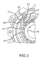
FIG. 3 illustrates an anti-rotation device according to various embodiments; -
FIG. 4 illustrates an anti-rotation device according to various embodiments; and -
FIG. 5 illustrates an anti-rotation device according to various embodiments in a turbofan engine. - The detailed description of exemplary embodiments herein makes reference to the accompanying drawings, which show exemplary embodiments by way of illustration and their best mode. While these exemplary embodiments are described in sufficient detail to enable those skilled in the art to practice the inventions, it should be understood that other embodiments may be realized and that logical, chemical and mechanical changes may be made without departing from the scope of the disclosure. Thus, the detailed description herein is presented for purposes of illustration only and not of limitation. For example, the steps recited in any of the method or process descriptions may be executed in any order and are not necessarily limited to the order presented.
- Furthermore, any reference to singular includes plural embodiments, and any reference to more than one component or step may include a singular embodiment or step. Also, any reference to attached, fixed, connected or the like may include permanent, removable, temporary, partial, full and/or any other possible attachment option. Additionally, any reference to without contact (or similar phrases) may also include reduced contact or minimal contact.
- As used herein, phrases such as "make contact with," "coupled to," "touch," "interface with" and "engage" may be used interchangeably.
- As used herein, "aft" refers to the direction associated with the tail (e.g., the back end) of an aircraft, or generally, to the direction of exhaust of the gas turbine engine. As used herein, "forward" refers to the direction associated with the nose (e.g., the front end) of an aircraft, or generally, to the direction of flight or motion.
- In various embodiments and with reference to
FIG. 1 , agas turbine engine 20 is provided.Gas turbine engine 20 may be a two-spool turbofan that generally incorporates afan section 22, acompressor section 24, acombustor section 26 and aturbine section 28. Alternative engines may include, for example, an augmentor section among other systems or features. In operation,fan section 22 can drive air along a bypass flow-path B whilecompressor section 24 can drive air along a core flow-path C for compression and communication intocombustor section 26 then expansion throughturbine section 28. Although depicted as a turbofangas turbine engine 20 herein, it should be understood that the concepts described herein are not limited to use with turbofans as the teachings may be applied to other types of turbine engines including three-spool architectures. -
Gas turbine engine 20 may generally comprise alow speed spool 30 and ahigh speed spool 32 mounted for rotation about an engine central longitudinal axis A-A' relative to an enginestatic structure 36 viaseveral bearing systems 38, 38-1, and 38-2. It should be understood thatvarious bearing systems 38 at various locations may alternatively or additionally be provided, including for example,bearing system 38, bearing system 38-1, and bearing system 38-2. -
Low speed spool 30 may generally comprise aninner shaft 40 that interconnects afan 42, a low pressure (or first)compressor section 44 and a low pressure (or first)turbine section 46.Inner shaft 40 may be connected tofan 42 through a gearedarchitecture 48 that can drivefan 42 at a lower speed thanlow speed spool 30. Gearedarchitecture 48 may comprise agear assembly 60 enclosed within agear housing 62.Gear assembly 60 couplesinner shaft 40 to a rotating fan structure.High speed spool 32 may comprise anouter shaft 50 that interconnects a high pressure (or second)compressor section 52 and high pressure (or second)turbine section 54. Acombustor 56 may be located betweenhigh pressure compressor 52 andhigh pressure turbine 54. Amid-turbine frame 57 of enginestatic structure 36 may be located generally betweenhigh pressure turbine 54 andlow pressure turbine 46.Mid-turbine frame 57 may support one or morebearing systems 38 inturbine section 28.Inner shaft 40 andouter shaft 50 may be concentric and rotate via bearingsystems 38 about the engine central longitudinal axis A-A', which is collinear with their longitudinal axes. As used herein, a "high pressure" compressor or turbine experiences a higher pressure than a corresponding "low pressure" compressor or turbine. - The core airflow C may be compressed by low
pressure compressor section 44 thenhigh pressure compressor 52, mixed and burned with fuel incombustor 56, then expanded overhigh pressure turbine 54 andlow pressure turbine 46.Mid-turbine frame 57 includesairfoils 59 which are in the core airflow path.Turbines low speed spool 30 andhigh speed spool 32 in response to the expansion. -
Gas turbine engine 20 may be, for example, a high-bypass geared aircraft engine. In various embodiments, gearedarchitecture 48 may be an epicyclic gear train, such as a star gear system (sun gear in meshing engagement with a plurality of star gears supported by a carrier and in meshing engagement with a ring gear) or other gear system.Gear architecture 48 may have a gear reduction ratio of greater than about 2.3 andlow pressure turbine 46 may have a pressure ratio that is greater than about 5. In various embodiments, the bypass ratio ofgas turbine engine 20 is greater than about ten (10:1). In various embodiments, the diameter offan 42 may be significantly larger than that of thelow pressure compressor 44, and thelow pressure turbine 46 may have a pressure ratio that is greater than about 5:1.Low pressure turbine 46 pressure ratio may be measured prior to inlet oflow pressure turbine 46 as related to the pressure at the outlet oflow pressure turbine 46 prior to an exhaust nozzle. It should be understood, however, that the above parameters are exemplary of various embodiments of a suitable geared architecture engine and that the present disclosure contemplates other gas turbine engines including direct drive turbofans. - With reference to
FIG. 1 ,gas turbine engine 20 may generally include multiple of modules including for example, afan case module 61, anintermediate case module 63, a Low Pressure Compressor (LPC)module 64, a High Pressure Compressor (HPC)module 66, adiffuser module 68, a High Pressure Turbine (HPT)module 70, a mid-turbine frame (MTF)module 72, a Low Pressure Turbine (LPT)module 74, and a Turbine Exhaust Case (TEC)module 76. - As described above, an anti-rotational device may be used to prevent reverse windmilling in a turbofan engine. In particular, an anti-rotational device may be disposed in the low pressure turbine to prevent rotation in an undesired direction. For example, an anti-rotational device may be configured to allow rotation in a first direction (e.g., clockwise) and to limit all or nearly all rotation in a second direction (e.g., counter clockwise). Moreover, an anti-rotational device may be configured to limit mechanical contact at or above certain angular velocities. In that regard, lower angular velocities may be associated with a level of mechanical contact between various components but, after a low pressure turbine achieves a given angular velocity, the contact may be reduced or eliminated.
- With reference to
FIG. 2 ,anti-rotational device 200 is shown.Ratchet 202 is shown disposed coaxially topawl carrier 212.Pawl carrier 212 is configured to rotate whileratchet 202 is constrained from rotation.Ratchet 202 has a variable radius. For example, the radius from the axis of rotation may vary in length along the inner circumference ofratchet 202. As shown, for example, the radius drawn nearratchet tooth 204 is larger than the radius twenty degrees clockwiseform ratchet tooth 204. -
Pawl carrier 212 is configured to rotate withinratchet 202.Pawl carrier 212 is clamped bypawl nut 214 onto a central shaft, such as lowpressure turbine shaft 501 with brief reference toFIG. 5 . With reference back toFIG. 2 , the central shaft may be driven by a motor or other device that may cause rotation of the central shaft. In various embodiments, the central shaft is a low pressure turbine shaft.Pawl nut 214 transfers torque topawl carrier 212 and thus drives rotation ofpawl carrier 212.Pawl carrier 212 is shown rotating in a counter-clockwise direction. In particular,pawl carrier 212 is shown rotating at an angular velocity below a predetermined angular velocity. -
Pawls pawl carrier 212. In other words,pawl 206 is one hundred twenty (120) degrees frompawl 208 which in turn is one hundred twenty (120) degrees frompawl 210, which in turn is one hundred twenty (120) degrees frompawl 206. -
Pawls pawls - As
pawl carrier 212 rotates in counterclockwise direction at an angular velocity below a predetermined angular velocity, each pawl will contact the ratchet near the ratchet tooth. In that regard,pawls pawls pawl carrier 212. With brief reference toFIG. 3 , stoppin 316 is shown. A stop pin may be disposed in an axial direction and provide a contact point for a pawl to prevent the pawl from contactingpawl carrier 212. In that regard,pawl 206 may rotate radially inward about pivot joint 302 andcontact stop pin 316. - With reference to
FIG. 3 ,pawl carrier 212 is shown rotating in a clockwise direction.Ratchet tooth 204 is shown interacting withpawl 206. In that regard,pawl 206 may interact (i.e., contact)ratchet tooth 204 and thus preventpawl carrier 212 from rotating in a clockwise direction. -
Pawl 206 is shown pivotably mounted topawl carrier 212 on apivot joint 302. Pivot joint 302 allowspawl 206 to rotate freely about pivot joint 302. Pivot joint 302 may comprise any suitable joint that is configured to allowpawl 206 to pivot. For a example, a post and bushing mating may be used as pivot joint 302. Pivot joint 302 may be suitably lubricated, for example, using a solid state lubricant and/or liquid lubricant. Pivot joint 302 may also comprise one or more materials that are coated and/or plated with or comprised of a low friction material. For example, portions of pivot joint 302 may be coated with polytetrafluoroethylene ("PTFE"). In various embodiments, pivot joint 302 is disposed at or near the geometric center ofpawl 206. -
Pawl 206 comprisescounterweight portion 304 andcontact portion 314.Pawl 206 may comprise a single integral piece comprisingcounterweight portion 304 andcontact portion 314.Counterweight portion 304 may be integral topawl 206 and may be formed by any suitable means, for example, by forging, casting, stamping, negative manufacturing techniques, additive manufacturing techniques and/or other methods of manufacture.Counterweight portion 304 may be configured such that the center of mass ofpawl 206 is more proximate a terminus ofcounterweight portion 304 than a terminus ofcontact portion 314.Counterweight portion 304 may be configured to have a "scoop" or cut out and/or a portions of greater thickness and/or mass when compared with other portions ofpawl 206. -
Torsion spring 310 may be disposed to exert a radial outward force uponpawl 206, and similar torsion springs may be similarly disposed with respect topawls torsion spring 310 exerts a rotational force onpawl 206 that tends to pivotpawl 206 about pivot joint 302 in a radially outward direction.Torsion spring 310 may be made from any suitable material, for example, stainless steel. - Upon rotation in
clockwise direction 306,contact portion 314 may contactratchet tooth 204, preventing rotation. In the embodiment shown inFIG. 3 , therefore, the maximum rotation inclockwise direction 306 that would be possible is one hundred twenty degrees, aspawls - With reference to
FIG. 4 ,pawl carrier 212 is shown rotating incounter-clockwise direction 406 at an angular velocity above a predetermined angular velocity. In response to rotation incounter-clockwise direction 406, a force will be exerted on counterweight portion 304 (e.g., centrifugal force). This force uponcounterweight portion 304 will tend to counteract the rotational force exerted bytorsion spring 310 onpawl 206. Stated another way, at lower angular velocities, thecounterweight portion 304 will begin to oppose the force exerted by thetorsion spring 310. As angular velocity increases, the force exerted oncounterweight portion 304 may begin to overcome the force exerted by thetorsion spring 310 andcause contact portion 314 to begin to rotate about pivot joint 302 in a radially inward direction. Conversely, the force will be exerted oncounterweight portion 304 will causecounterweight portion 304 to rotate radially outward about pivot joint 302. In response to the angular velocity ofpawl carrier 212 reaching the predetermined velocity,counterweight portion 304 will movecontact portion 314 radially inward so thatcontact portion 314 no longer contacts the ratchet during each revolution. In that regard, rotation incounter-clockwise direction 406 is permitted, however, aspawl 210 may rotatepast ratchet tooth 204 in a counter clockwise direction without interference fromratchet tooth 204. - The tuning of
torsion spring 310 and the predetermined velocity may be adjusted to suit various design considerations, and it is contemplated that any torsion spring and predetermined velocity may be accomplished. In various embodiments, the predetermined velocity may be between about 5 revolutions per minutes ("rpm") and about 10,000 rpm, between about 300 revolutions per minutes ("rpm") and about 4,000 rpm, and/or about 600 revolutions per minutes ("rpm") and about 800 rpm, where the term "about" in this context only refers to +/- 50 rpm. - Hooke's law may be adapted for use in torsion springs and may take the form of:

- In this equation, τ represents torque exerted by the spring, θ is the angle from the equilibrium position and κ is the torsional spring constant. Though a torsion spring of any spring constant may be used, in various embodiments, torsion springs may be used having constants of about 0.1 pound inches (0.12 Kgcm) per degree and about 0.3 pound inches (0.35 Kgcm) per degree, and about 0.14 pound inches (0.16 Kgcm) per degree and about 0.24 pound inches (0.28 Kgcm) per degree, and about 0.17 pound inches (0.20 Kgcm) per degree, where the term "about" in this context only refers to +/- 0.02 pound inches (0.023 Kgcm) per degree.
- In that regard, Hooke's law may be used to find the torque exerted by the torsion spring and such information may be used to tune the mass and location of
counterweight portion 304. - With reference to
FIG. 5 , a low pressure turbine is shown in cross section havinganti-rotational device 200.Ratchet 202 is shown disposed coaxially topawl carrier 212.Ratchet housing 502 constrains theratchet 202 from rotation.Tube 504 andrear cover 506 are also shownproximate ratchet housing 502. Lowpressure turbine shaft 501 is shown coupled topawl carrier 212 viapawl nut 214.Key washer 512 and retainingring 514 are shown proximate thepawl carrier 212. - Benefits, other advantages, and solutions to problems have been described herein with regard to specific embodiments. Furthermore, the connecting lines shown in the various figures contained herein are intended to represent exemplary functional relationships and/or physical couplings between the various elements. It should be noted that many alternative or additional functional relationships or physical connections may be present in a practical system. However, the benefits, advantages, solutions to problems, and any elements that may cause any benefit, advantage, or solution to occur or become more pronounced are not to be construed as critical, required, or essential features or elements of the inventions. The scope of the inventions is accordingly to be limited by nothing other than the appended claims, in which reference to an element in the singular is not intended to mean "one and only one" unless explicitly so stated, but rather "one or more." Moreover, where a phrase similar to "at least one of A, B, or C" is used in the claims, it is intended that the phrase be interpreted to mean that A alone may be present in an embodiment, B alone may be present in an embodiment, C alone may be present in an embodiment, or that any combination of the elements A, B and C may be present in a single embodiment; for example, A and B, A and C, B and C, or A and B and C.
- Systems, methods and apparatus are provided herein. In the detailed description herein, references to "one embodiment", "an embodiment", "various embodiments", etc., indicate that the embodiment described may include a particular feature, structure, or characteristic, but every embodiment may not necessarily include the particular feature, structure, or characteristic. Moreover, such phrases are not necessarily referring to the same embodiment. Further, when a particular feature, structure, or characteristic is described in connection with an embodiment, it is submitted that it is within the knowledge of one skilled in the art to affect such feature, structure, or characteristic in connection with other embodiments whether or not explicitly described. After reading the description, it will be apparent to one skilled in the relevant art(s) how to implement the disclosure in alternative embodiments.
- Furthermore, no element, component, or method step in the present disclosure is intended to be dedicated to the public regardless of whether the element, component, or method step is explicitly recited in the claims. No claim element herein is to be construed under the provisions of 35 U.S.C. 112(f), unless the element is expressly recited using the phrase "means for." As used herein, the terms "comprises", "comprising", or any other variation thereof, are intended to cover a non-exclusive inclusion, such that a process, method, article, or apparatus that comprises a list of elements does not include only those elements but may include other elements not expressly listed or inherent to such process, method, article, or apparatus.
Claims (15)
- An anti-rotational system (200) comprising:a pawl carrier (212) mounted for rotation within a ratchet (202), the pawl carrier (212) having an axis of rotation; anda pawl (206,208,210) pivotably mounted to the pawl carrier (212) on a pivot joint (302), the pawl (206,208,210) having a contact portion (314) and a counterweight portion (304),wherein the pivot joint (302) is between the contact portion (314) and the counterweight portion (304);wherein the counterweight portion (304) is configured to be radially inward of the contact portion (314), in response to rotation of the pawl carrier (212) in a first rotational direction at an angular velocity less than a predetermined angular velocity.
- The anti-rotational system of claim 1, wherein the counterweight portion (304) is configured to be radially outward of the contact portion (314) in response to rotation of the pawl carrier (212) at an angular velocity greater than a predetermined angular velocity.
- The anti-rotational system of claim 1 or 2, wherein a center of mass of the pawl (206,208,210) is located more proximate the counterweight portion (304) than the contact portion (314).
- The anti-rotational system of claim 1, 2 or 3, wherein the pawl (206,208,210) is comprised of at least one of stainless steel and a chromium-nickel-tungsten martensitic alloy.
- The anti-rotational system of any preceding claim, wherein the ratchet (202) comprises a ratchet tooth (204).
- The anti-rotational system of claim 5, wherein the contact portion (314) is configured to contact the ratchet tooth (204) in response to rotation of the pawl carrier (212) in a second rotational direction.
- The anti-rotational system of claim 6, wherein the interaction between the contact portion (314) and the ratchet tooth (204) prevent rotation of the pawl carrier (212) in the second rotational direction.
- The anti-rotational system of any preceding claim, wherein the pawl carrier (212) and ratchet (202) are mounted to rotate coaxially.
- The anti-rotational system of any preceding claim, wherein a second pawl (208) is pivotably mounted to the pawl carrier (212) and a third pawl (210) is pivotably mounted to the pawl carrier (212), wherein, optionally, the pawl, the second pawl and the third pawl (206,208,210) are spaced 120 degrees apart on the pawl carrier (212).
- The anti-rotational system of any preceding claim, wherein the ratchet (202) has a variable radius.
- The anti-rotational system of any preceding claim, wherein the predetermined angular velocity is between about 500rpm and 1500rpm.
- The anti-rotational system of any preceding claim, wherein the pivot joint (302) is at least one of lubricated and plated.
- The anti-rotational system of any preceding claim, wherein a torsion spring (310) is disposed proximate the pivot joint (302) and configured to exert an outward radial force on the contact portion (314) of the pawl (206,208,210).
- The anti-rotational system of any preceding claim, further comprising a stop pin (316) disposed on the pawl carrier (212).
- The anti-rotational system of any preceding claim, wherein the pawl (206,208,210) comprises a cutout portion.
Applications Claiming Priority (1)
| Application Number | Priority Date | Filing Date | Title |
|---|---|---|---|
| US201461977765P | 2014-04-10 | 2014-04-10 |
Publications (2)
| Publication Number | Publication Date |
|---|---|
| EP2930333A1 true EP2930333A1 (en) | 2015-10-14 |
| EP2930333B1 EP2930333B1 (en) | 2021-06-02 |
Family
ID=52997214
Family Applications (1)
| Application Number | Title | Priority Date | Filing Date |
|---|---|---|---|
| EP15163143.9A Active EP2930333B1 (en) | 2014-04-10 | 2015-04-10 | Anti-rotational systems and methods |
Country Status (2)
| Country | Link |
|---|---|
| US (1) | US10006506B2 (en) |
| EP (1) | EP2930333B1 (en) |
Cited By (1)
| Publication number | Priority date | Publication date | Assignee | Title |
|---|---|---|---|---|
| EP3396144A1 (en) * | 2017-04-28 | 2018-10-31 | Rolls-Royce Deutschland Ltd & Co KG | Gas turbine engine with a geared turbofan arrangement |
Families Citing this family (2)
| Publication number | Priority date | Publication date | Assignee | Title |
|---|---|---|---|---|
| US9689444B2 (en) * | 2014-04-10 | 2017-06-27 | United Technologies Corporation | Damped anti-rotational systems |
| CN109649696B (en) * | 2018-12-29 | 2022-05-31 | 西北工业大学 | Tray type micro-nano satellite separation device capable of roughly controlling angular velocity of rotation |
Citations (3)
| Publication number | Priority date | Publication date | Assignee | Title |
|---|---|---|---|---|
| CH256394A (en) * | 1947-02-20 | 1948-08-15 | Schweizerische Lokomotiv | Ratchet lock. |
| GB703262A (en) * | 1950-10-16 | 1954-02-03 | Rolls Royce | Improvements in or relating to gas-turbine engines |
| US3521505A (en) * | 1968-07-09 | 1970-07-21 | Garrett Corp | Transmission means |
Family Cites Families (7)
| Publication number | Priority date | Publication date | Assignee | Title |
|---|---|---|---|---|
| US2308926A (en) * | 1940-03-26 | 1943-01-19 | Kreis Friedrich | Pawl freewheel |
| US4964344A (en) * | 1989-04-28 | 1990-10-23 | Mid-West Conveyor Company, Inc. | Side link pusher dog with lubrication passage |
| US5183387A (en) * | 1992-01-03 | 1993-02-02 | Allied-Signal, Inc. | Fault-tolerant apparatus for controlling blade pitch |
| DE10196701T1 (en) * | 2000-09-29 | 2003-09-04 | Jin Feng | Overrunning clutch |
| US7614486B2 (en) * | 2004-07-27 | 2009-11-10 | Ford Global Technologies, Llc | Retention of an actuating spring in a one-way clutch or brake |
| DE102004040810A1 (en) * | 2004-08-24 | 2006-03-02 | Ina-Schaeffler Kg | Device for damping torsional vibrations |
| EP2388156B1 (en) * | 2010-05-19 | 2012-05-09 | Pewag Schneeketten GMBH & Co KG | Tightener |
-
2015
- 2015-03-17 US US14/660,575 patent/US10006506B2/en active Active
- 2015-04-10 EP EP15163143.9A patent/EP2930333B1/en active Active
Patent Citations (3)
| Publication number | Priority date | Publication date | Assignee | Title |
|---|---|---|---|---|
| CH256394A (en) * | 1947-02-20 | 1948-08-15 | Schweizerische Lokomotiv | Ratchet lock. |
| GB703262A (en) * | 1950-10-16 | 1954-02-03 | Rolls Royce | Improvements in or relating to gas-turbine engines |
| US3521505A (en) * | 1968-07-09 | 1970-07-21 | Garrett Corp | Transmission means |
Cited By (2)
| Publication number | Priority date | Publication date | Assignee | Title |
|---|---|---|---|---|
| EP3396144A1 (en) * | 2017-04-28 | 2018-10-31 | Rolls-Royce Deutschland Ltd & Co KG | Gas turbine engine with a geared turbofan arrangement |
| US10823082B2 (en) | 2017-04-28 | 2020-11-03 | Rolls-Royce Deutschland Ltd & Co Kg | Gas turbine engine with a geared turbofan arrangement |
Also Published As
| Publication number | Publication date |
|---|---|
| US10006506B2 (en) | 2018-06-26 |
| US20150292575A1 (en) | 2015-10-15 |
| EP2930333B1 (en) | 2021-06-02 |
Similar Documents
| Publication | Publication Date | Title |
|---|---|---|
| US10787929B2 (en) | Lubricating fluid damped anti-rotational systems | |
| US10591004B2 (en) | Damped anti-rotational systems | |
| EP3163034B1 (en) | Gas turbine engine comprising two pumps for lubrication in both directions of rotation of the fan | |
| EP3467272A1 (en) | Geared architecture for high speed and small volume fan drive turbine | |
| EP3093467B1 (en) | Lubrication system for geared gas turbine engine | |
| EP3112599A1 (en) | Transfer tube and turbine section comprising transfer tube | |
| CN110234839B (en) | Flexible coupling shafts for turbine engines | |
| CN110268147B (en) | Method and system for connecting a turbine engine gearbox to an engine core | |
| EP2961970B1 (en) | Gas turbine engine assembly and method of controlling rotation of a gas turbine engine fan | |
| WO2013184429A1 (en) | Front bearing support for a fan drive gear system | |
| EP2930333B1 (en) | Anti-rotational systems and methods | |
| EP2930331B1 (en) | Systems and methods for shock load reduction | |
| EP3401562B1 (en) | Bearing with non-uniform cage clearance | |
| EP3081748B1 (en) | Gas turbine engine system comprising a seal ring | |
| EP2930389B1 (en) | Torsion spring internal damper | |
| EP3098387A1 (en) | Installation fault tolerant damper | |
| EP3418618B1 (en) | Middle threaded fitting |
Legal Events
| Date | Code | Title | Description |
|---|---|---|---|
| PUAI | Public reference made under article 153(3) epc to a published international application that has entered the european phase |
Free format text: ORIGINAL CODE: 0009012 |
|
| AK | Designated contracting states |
Kind code of ref document: A1 Designated state(s): AL AT BE BG CH CY CZ DE DK EE ES FI FR GB GR HR HU IE IS IT LI LT LU LV MC MK MT NL NO PL PT RO RS SE SI SK SM TR |
|
| AX | Request for extension of the european patent |
Extension state: BA ME |
|
| 17P | Request for examination filed |
Effective date: 20160414 |
|
| RBV | Designated contracting states (corrected) |
Designated state(s): AL AT BE BG CH CY CZ DE DK EE ES FI FR GB GR HR HU IE IS IT LI LT LU LV MC MK MT NL NO PL PT RO RS SE SI SK SM TR |
|
| RAP1 | Party data changed (applicant data changed or rights of an application transferred) |
Owner name: UNITED TECHNOLOGIES CORPORATION |
|
| STAA | Information on the status of an ep patent application or granted ep patent |
Free format text: STATUS: EXAMINATION IS IN PROGRESS |
|
| 17Q | First examination report despatched |
Effective date: 20181009 |
|
| GRAP | Despatch of communication of intention to grant a patent |
Free format text: ORIGINAL CODE: EPIDOSNIGR1 |
|
| STAA | Information on the status of an ep patent application or granted ep patent |
Free format text: STATUS: GRANT OF PATENT IS INTENDED |
|
| INTG | Intention to grant announced |
Effective date: 20201222 |
|
| RAP1 | Party data changed (applicant data changed or rights of an application transferred) |
Owner name: RAYTHEON TECHNOLOGIES CORPORATION |
|
| GRAS | Grant fee paid |
Free format text: ORIGINAL CODE: EPIDOSNIGR3 |
|
| GRAA | (expected) grant |
Free format text: ORIGINAL CODE: 0009210 |
|
| STAA | Information on the status of an ep patent application or granted ep patent |
Free format text: STATUS: THE PATENT HAS BEEN GRANTED |
|
| REG | Reference to a national code |
Ref country code: CH Ref legal event code: EP |
|
| AK | Designated contracting states |
Kind code of ref document: B1 Designated state(s): AL AT BE BG CH CY CZ DE DK EE ES FI FR GB GR HR HU IE IS IT LI LT LU LV MC MK MT NL NO PL PT RO RS SE SI SK SM TR |
|
| REG | Reference to a national code |
Ref country code: GB Ref legal event code: FG4D |
|
| REG | Reference to a national code |
Ref country code: AT Ref legal event code: REF Ref document number: 1398648 Country of ref document: AT Kind code of ref document: T Effective date: 20210615 |
|
| REG | Reference to a national code |
Ref country code: IE Ref legal event code: FG4D |
|
| REG | Reference to a national code |
Ref country code: DE Ref legal event code: R096 Ref document number: 602015069921 Country of ref document: DE |
|
| REG | Reference to a national code |
Ref country code: LT Ref legal event code: MG9D |
|
| PG25 | Lapsed in a contracting state [announced via postgrant information from national office to epo] |
Ref country code: LT Free format text: LAPSE BECAUSE OF FAILURE TO SUBMIT A TRANSLATION OF THE DESCRIPTION OR TO PAY THE FEE WITHIN THE PRESCRIBED TIME-LIMIT Effective date: 20210602 Ref country code: FI Free format text: LAPSE BECAUSE OF FAILURE TO SUBMIT A TRANSLATION OF THE DESCRIPTION OR TO PAY THE FEE WITHIN THE PRESCRIBED TIME-LIMIT Effective date: 20210602 Ref country code: BG Free format text: LAPSE BECAUSE OF FAILURE TO SUBMIT A TRANSLATION OF THE DESCRIPTION OR TO PAY THE FEE WITHIN THE PRESCRIBED TIME-LIMIT Effective date: 20210902 Ref country code: HR Free format text: LAPSE BECAUSE OF FAILURE TO SUBMIT A TRANSLATION OF THE DESCRIPTION OR TO PAY THE FEE WITHIN THE PRESCRIBED TIME-LIMIT Effective date: 20210602 |
|
| REG | Reference to a national code |
Ref country code: NL Ref legal event code: MP Effective date: 20210602 |
|
| REG | Reference to a national code |
Ref country code: AT Ref legal event code: MK05 Ref document number: 1398648 Country of ref document: AT Kind code of ref document: T Effective date: 20210602 |
|
| PG25 | Lapsed in a contracting state [announced via postgrant information from national office to epo] |
Ref country code: LV Free format text: LAPSE BECAUSE OF FAILURE TO SUBMIT A TRANSLATION OF THE DESCRIPTION OR TO PAY THE FEE WITHIN THE PRESCRIBED TIME-LIMIT Effective date: 20210602 Ref country code: GR Free format text: LAPSE BECAUSE OF FAILURE TO SUBMIT A TRANSLATION OF THE DESCRIPTION OR TO PAY THE FEE WITHIN THE PRESCRIBED TIME-LIMIT Effective date: 20210903 Ref country code: SE Free format text: LAPSE BECAUSE OF FAILURE TO SUBMIT A TRANSLATION OF THE DESCRIPTION OR TO PAY THE FEE WITHIN THE PRESCRIBED TIME-LIMIT Effective date: 20210602 Ref country code: RS Free format text: LAPSE BECAUSE OF FAILURE TO SUBMIT A TRANSLATION OF THE DESCRIPTION OR TO PAY THE FEE WITHIN THE PRESCRIBED TIME-LIMIT Effective date: 20210602 Ref country code: NO Free format text: LAPSE BECAUSE OF FAILURE TO SUBMIT A TRANSLATION OF THE DESCRIPTION OR TO PAY THE FEE WITHIN THE PRESCRIBED TIME-LIMIT Effective date: 20210902 Ref country code: PL Free format text: LAPSE BECAUSE OF FAILURE TO SUBMIT A TRANSLATION OF THE DESCRIPTION OR TO PAY THE FEE WITHIN THE PRESCRIBED TIME-LIMIT Effective date: 20210602 |
|
| PG25 | Lapsed in a contracting state [announced via postgrant information from national office to epo] |
Ref country code: EE Free format text: LAPSE BECAUSE OF FAILURE TO SUBMIT A TRANSLATION OF THE DESCRIPTION OR TO PAY THE FEE WITHIN THE PRESCRIBED TIME-LIMIT Effective date: 20210602 Ref country code: CZ Free format text: LAPSE BECAUSE OF FAILURE TO SUBMIT A TRANSLATION OF THE DESCRIPTION OR TO PAY THE FEE WITHIN THE PRESCRIBED TIME-LIMIT Effective date: 20210602 Ref country code: SM Free format text: LAPSE BECAUSE OF FAILURE TO SUBMIT A TRANSLATION OF THE DESCRIPTION OR TO PAY THE FEE WITHIN THE PRESCRIBED TIME-LIMIT Effective date: 20210602 Ref country code: SK Free format text: LAPSE BECAUSE OF FAILURE TO SUBMIT A TRANSLATION OF THE DESCRIPTION OR TO PAY THE FEE WITHIN THE PRESCRIBED TIME-LIMIT Effective date: 20210602 Ref country code: ES Free format text: LAPSE BECAUSE OF FAILURE TO SUBMIT A TRANSLATION OF THE DESCRIPTION OR TO PAY THE FEE WITHIN THE PRESCRIBED TIME-LIMIT Effective date: 20210602 Ref country code: PT Free format text: LAPSE BECAUSE OF FAILURE TO SUBMIT A TRANSLATION OF THE DESCRIPTION OR TO PAY THE FEE WITHIN THE PRESCRIBED TIME-LIMIT Effective date: 20211004 Ref country code: RO Free format text: LAPSE BECAUSE OF FAILURE TO SUBMIT A TRANSLATION OF THE DESCRIPTION OR TO PAY THE FEE WITHIN THE PRESCRIBED TIME-LIMIT Effective date: 20210602 Ref country code: NL Free format text: LAPSE BECAUSE OF FAILURE TO SUBMIT A TRANSLATION OF THE DESCRIPTION OR TO PAY THE FEE WITHIN THE PRESCRIBED TIME-LIMIT Effective date: 20210602 Ref country code: AT Free format text: LAPSE BECAUSE OF FAILURE TO SUBMIT A TRANSLATION OF THE DESCRIPTION OR TO PAY THE FEE WITHIN THE PRESCRIBED TIME-LIMIT Effective date: 20210602 |
|
| REG | Reference to a national code |
Ref country code: DE Ref legal event code: R097 Ref document number: 602015069921 Country of ref document: DE |
|
| PLBE | No opposition filed within time limit |
Free format text: ORIGINAL CODE: 0009261 |
|
| STAA | Information on the status of an ep patent application or granted ep patent |
Free format text: STATUS: NO OPPOSITION FILED WITHIN TIME LIMIT |
|
| PG25 | Lapsed in a contracting state [announced via postgrant information from national office to epo] |
Ref country code: DK Free format text: LAPSE BECAUSE OF FAILURE TO SUBMIT A TRANSLATION OF THE DESCRIPTION OR TO PAY THE FEE WITHIN THE PRESCRIBED TIME-LIMIT Effective date: 20210602 |
|
| 26N | No opposition filed |
Effective date: 20220303 |
|
| PG25 | Lapsed in a contracting state [announced via postgrant information from national office to epo] |
Ref country code: AL Free format text: LAPSE BECAUSE OF FAILURE TO SUBMIT A TRANSLATION OF THE DESCRIPTION OR TO PAY THE FEE WITHIN THE PRESCRIBED TIME-LIMIT Effective date: 20210602 |
|
| PG25 | Lapsed in a contracting state [announced via postgrant information from national office to epo] |
Ref country code: IT Free format text: LAPSE BECAUSE OF FAILURE TO SUBMIT A TRANSLATION OF THE DESCRIPTION OR TO PAY THE FEE WITHIN THE PRESCRIBED TIME-LIMIT Effective date: 20210602 |
|
| REG | Reference to a national code |
Ref country code: CH Ref legal event code: PL |
|
| REG | Reference to a national code |
Ref country code: BE Ref legal event code: MM Effective date: 20220430 |
|
| PG25 | Lapsed in a contracting state [announced via postgrant information from national office to epo] |
Ref country code: MC Free format text: LAPSE BECAUSE OF FAILURE TO SUBMIT A TRANSLATION OF THE DESCRIPTION OR TO PAY THE FEE WITHIN THE PRESCRIBED TIME-LIMIT Effective date: 20210602 Ref country code: LU Free format text: LAPSE BECAUSE OF NON-PAYMENT OF DUE FEES Effective date: 20220410 Ref country code: LI Free format text: LAPSE BECAUSE OF NON-PAYMENT OF DUE FEES Effective date: 20220430 Ref country code: CH Free format text: LAPSE BECAUSE OF NON-PAYMENT OF DUE FEES Effective date: 20220430 |
|
| PG25 | Lapsed in a contracting state [announced via postgrant information from national office to epo] |
Ref country code: BE Free format text: LAPSE BECAUSE OF NON-PAYMENT OF DUE FEES Effective date: 20220430 |
|
| PG25 | Lapsed in a contracting state [announced via postgrant information from national office to epo] |
Ref country code: IE Free format text: LAPSE BECAUSE OF NON-PAYMENT OF DUE FEES Effective date: 20220410 |
|
| P01 | Opt-out of the competence of the unified patent court (upc) registered |
Effective date: 20230520 |
|
| PG25 | Lapsed in a contracting state [announced via postgrant information from national office to epo] |
Ref country code: HU Free format text: LAPSE BECAUSE OF FAILURE TO SUBMIT A TRANSLATION OF THE DESCRIPTION OR TO PAY THE FEE WITHIN THE PRESCRIBED TIME-LIMIT; INVALID AB INITIO Effective date: 20150410 |
|
| PG25 | Lapsed in a contracting state [announced via postgrant information from national office to epo] |
Ref country code: MK Free format text: LAPSE BECAUSE OF FAILURE TO SUBMIT A TRANSLATION OF THE DESCRIPTION OR TO PAY THE FEE WITHIN THE PRESCRIBED TIME-LIMIT Effective date: 20210602 Ref country code: CY Free format text: LAPSE BECAUSE OF FAILURE TO SUBMIT A TRANSLATION OF THE DESCRIPTION OR TO PAY THE FEE WITHIN THE PRESCRIBED TIME-LIMIT Effective date: 20210602 |
|
| PG25 | Lapsed in a contracting state [announced via postgrant information from national office to epo] |
Ref country code: TR Free format text: LAPSE BECAUSE OF FAILURE TO SUBMIT A TRANSLATION OF THE DESCRIPTION OR TO PAY THE FEE WITHIN THE PRESCRIBED TIME-LIMIT Effective date: 20210602 |
|
| PG25 | Lapsed in a contracting state [announced via postgrant information from national office to epo] |
Ref country code: MT Free format text: LAPSE BECAUSE OF FAILURE TO SUBMIT A TRANSLATION OF THE DESCRIPTION OR TO PAY THE FEE WITHIN THE PRESCRIBED TIME-LIMIT Effective date: 20210602 |
|
| PGFP | Annual fee paid to national office [announced via postgrant information from national office to epo] |
Ref country code: DE Payment date: 20250319 Year of fee payment: 11 |
|
| REG | Reference to a national code |
Ref country code: DE Ref legal event code: R081 Ref document number: 602015069921 Country of ref document: DE Owner name: RTX CORPORATION (N.D.GES.D. STAATES DELAWARE),, US Free format text: FORMER OWNER: RAYTHEON TECHNOLOGIES CORPORATION, FARMINGTON, CT, US |
|
| PGFP | Annual fee paid to national office [announced via postgrant information from national office to epo] |
Ref country code: GB Payment date: 20260320 Year of fee payment: 12 |
|
| PGFP | Annual fee paid to national office [announced via postgrant information from national office to epo] |
Ref country code: FR Payment date: 20260319 Year of fee payment: 12 |