EP2930314A1 - Generator with controlled air cooling amplifier - Google Patents
Generator with controlled air cooling amplifier Download PDFInfo
- Publication number
- EP2930314A1 EP2930314A1 EP15162313.9A EP15162313A EP2930314A1 EP 2930314 A1 EP2930314 A1 EP 2930314A1 EP 15162313 A EP15162313 A EP 15162313A EP 2930314 A1 EP2930314 A1 EP 2930314A1
- Authority
- EP
- European Patent Office
- Prior art keywords
- generator
- generator housing
- cooling air
- gas turbine
- air flow
- Prior art date
- Legal status (The legal status is an assumption and is not a legal conclusion. Google has not performed a legal analysis and makes no representation as to the accuracy of the status listed.)
- Granted
Links
Images

Classifications
-
- H—ELECTRICITY
- H02—GENERATION; CONVERSION OR DISTRIBUTION OF ELECTRIC POWER
- H02K—DYNAMO-ELECTRIC MACHINES
- H02K9/00—Arrangements for cooling or ventilating
- H02K9/02—Arrangements for cooling or ventilating by ambient air flowing through the machine
- H02K9/04—Arrangements for cooling or ventilating by ambient air flowing through the machine having means for generating a flow of cooling medium
-
- F—MECHANICAL ENGINEERING; LIGHTING; HEATING; WEAPONS; BLASTING
- F01—MACHINES OR ENGINES IN GENERAL; ENGINE PLANTS IN GENERAL; STEAM ENGINES
- F01D—NON-POSITIVE DISPLACEMENT MACHINES OR ENGINES, e.g. STEAM TURBINES
- F01D15/00—Adaptations of machines or engines for special use; Combinations of engines with devices driven thereby
- F01D15/10—Adaptations for driving, or combinations with, electric generators
-
- F—MECHANICAL ENGINEERING; LIGHTING; HEATING; WEAPONS; BLASTING
- F01—MACHINES OR ENGINES IN GENERAL; ENGINE PLANTS IN GENERAL; STEAM ENGINES
- F01D—NON-POSITIVE DISPLACEMENT MACHINES OR ENGINES, e.g. STEAM TURBINES
- F01D25/00—Component parts, details, or accessories, not provided for in, or of interest apart from, other groups
- F01D25/08—Cooling; Heating; Heat-insulation
-
- F—MECHANICAL ENGINEERING; LIGHTING; HEATING; WEAPONS; BLASTING
- F02—COMBUSTION ENGINES; HOT-GAS OR COMBUSTION-PRODUCT ENGINE PLANTS
- F02C—GAS-TURBINE PLANTS; AIR INTAKES FOR JET-PROPULSION PLANTS; CONTROLLING FUEL SUPPLY IN AIR-BREATHING JET-PROPULSION PLANTS
- F02C6/00—Plural gas-turbine plants; Combinations of gas-turbine plants with other apparatus; Adaptations of gas-turbine plants for special use
- F02C6/04—Gas-turbine plants providing heated or pressurised working fluid for other apparatus, e.g. without mechanical power output
- F02C6/06—Gas-turbine plants providing heated or pressurised working fluid for other apparatus, e.g. without mechanical power output providing compressed gas
- F02C6/08—Gas-turbine plants providing heated or pressurised working fluid for other apparatus, e.g. without mechanical power output providing compressed gas the gas being bled from the gas-turbine compressor
-
- H—ELECTRICITY
- H02—GENERATION; CONVERSION OR DISTRIBUTION OF ELECTRIC POWER
- H02K—DYNAMO-ELECTRIC MACHINES
- H02K7/00—Arrangements for handling mechanical energy structurally associated with dynamo-electric machines, e.g. structural association with mechanical driving motors or auxiliary dynamo-electric machines
- H02K7/18—Structural association of electric generators with mechanical driving motors, e.g. with turbines
- H02K7/1807—Rotary generators
- H02K7/1823—Rotary generators structurally associated with turbines or similar engines
-
- H—ELECTRICITY
- H02—GENERATION; CONVERSION OR DISTRIBUTION OF ELECTRIC POWER
- H02K—DYNAMO-ELECTRIC MACHINES
- H02K9/00—Arrangements for cooling or ventilating
-
- F—MECHANICAL ENGINEERING; LIGHTING; HEATING; WEAPONS; BLASTING
- F05—INDEXING SCHEMES RELATING TO ENGINES OR PUMPS IN VARIOUS SUBCLASSES OF CLASSES F01-F04
- F05D—INDEXING SCHEME FOR ASPECTS RELATING TO NON-POSITIVE-DISPLACEMENT MACHINES OR ENGINES, GAS-TURBINES OR JET-PROPULSION PLANTS
- F05D2220/00—Application
- F05D2220/70—Application in combination with
- F05D2220/76—Application in combination with an electrical generator
-
- F—MECHANICAL ENGINEERING; LIGHTING; HEATING; WEAPONS; BLASTING
- F05—INDEXING SCHEMES RELATING TO ENGINES OR PUMPS IN VARIOUS SUBCLASSES OF CLASSES F01-F04
- F05D—INDEXING SCHEME FOR ASPECTS RELATING TO NON-POSITIVE-DISPLACEMENT MACHINES OR ENGINES, GAS-TURBINES OR JET-PROPULSION PLANTS
- F05D2260/00—Function
- F05D2260/20—Heat transfer, e.g. cooling
-
- H—ELECTRICITY
- H02—GENERATION; CONVERSION OR DISTRIBUTION OF ELECTRIC POWER
- H02K—DYNAMO-ELECTRIC MACHINES
- H02K19/00—Synchronous motors or generators
- H02K19/16—Synchronous generators
- H02K19/38—Structural association of synchronous generators with exciting machines
-
- Y—GENERAL TAGGING OF NEW TECHNOLOGICAL DEVELOPMENTS; GENERAL TAGGING OF CROSS-SECTIONAL TECHNOLOGIES SPANNING OVER SEVERAL SECTIONS OF THE IPC; TECHNICAL SUBJECTS COVERED BY FORMER USPC CROSS-REFERENCE ART COLLECTIONS [XRACs] AND DIGESTS
- Y02—TECHNOLOGIES OR APPLICATIONS FOR MITIGATION OR ADAPTATION AGAINST CLIMATE CHANGE
- Y02T—CLIMATE CHANGE MITIGATION TECHNOLOGIES RELATED TO TRANSPORTATION
- Y02T50/00—Aeronautics or air transport
- Y02T50/60—Efficient propulsion technologies, e.g. for aircraft
Definitions
- An improved integrated design and control of a gas turbine is disclosed. More particularly, performance and efficiency are improved by optimizing the thermal control of the generator. The improvements are applicable to turbines used for propulsive power in marine, land, air, and underwater applications, as examples.
- gas turbine engine In a system having a typical gas turbine engine, electrical power is extracted via an electrical generator to supply electrical power to control systems, actuators, weapons systems, climate control systems, and the like. Electrical storage, such as a battery, is typically provided to operate such systems when the gas turbine engine is not running or to provide power for starting the gas turbine engine.
- the gas turbine engine includes a high pressure shaft and a lower pressure shaft, and the electrical generator is coupled to one of the high and low pressure shafts.
- the electrical generator commonly generates thermal energy when in operation. It is important to actively cool the electrical generator during operation in order to ensure proper operation as well as extend the lifespan of the generator. This is commonly accomplished through the use of a fan attached to the generator shaft. The fan adds undesirable weight and complexity to the generator. In addition, when the generator is operating at altitude in an aircraft there becomes a reduction in air density. This results in a reduction in air-flow, which in turn reduces cooling. Increasing fan velocity may be utilized to partially address these losses, but is not always efficient or practical.
- the electrical system includes at least two generator circuits, one coupled to a high pressure portion of a gas turbine engine and the other coupled to a low pressure portion of the gas turbine engine.
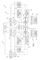
- Figure 1 illustrates an electrical system 10 in which a power plant or engine 12, such as a gas turbine engine, provides electrical power to a first power circuit 14 and a second power circuit 16.
- a system controller 18 is coupled to engine 12 and also to first and second circuits 14, 16.
- First power circuit 14 includes a motor/generator 20 and a General Control Unit (GCU) 22 coupled thereto.
- GCU 22 is also coupled to other components within first power circuit 14, such as a health monitoring and prognostics system 24, a thermal management system 26, and a power conversion/distribution system 28.
- First power circuit 14 also includes an energy storage system 30, an expansion module 32, and application electrical load(s) 34.
- System controller 18 is configured to regulate power flow (such as electrical currents and voltages within system 10) to provide power to various electrical busses.
- System controller 18 may also be configured to execute computer program instructions to control the operation of engine 12, including fuel flow, or the position of any variable geometry systems (e.g., from the flight control system of an aircraft or from a steering system of a ship).
- Health monitoring and prognostics system 24 is generally a unit that monitors the health of system components, and may be used to estimate component life based on sensor feedback received from components within engine 12.
- Thermal management system 26 includes pumps, expansion valves, and the like, as well as a controller, to provide coolant for the purposes of climate control, and other system operations.
- Power conversion/distribution system 28 receives electrical power from motor/generator 20 via GCU 22, and converts the power to a more useable form such as a DC voltage for storage in energy storage system 30, expansion module 32, and application electrical load(s) 34.
- the energy storage system 30 may include a battery or other energy storage system.
- Energy storage system 30 stores energy for providing power when engine 12 is not running (i.e., not generating power), but also to provide power to motor/generator 20 to provide starting power to engine 12 during startup.
- Expansion module 32 and application electrical load 34 represent additional electrical components that receive power from power conversion/distribution system 28.
- Second power circuit 16 similarly includes a motor/generator 36 and a GCU 38 coupled thereto. GCU 38 is also coupled to other components within second power circuit 16, such as a health monitoring and prognostics system 40, a thermal management system 42, and a power conversion/distribution system 44. Second power circuit 16 also includes an energy storage system 46, an expansion module 48, and application electrical load(s) 50. The components 36-50 of second power circuit 16 are similarly arranged as described with respect to first power circuit 14. Additionally, in one example electrical system 10 includes one or more additional motor/generators 52 and corresponding GCUs 54 as well, which may be coupled to a gas turbine engine as will be further described. Thus, the system 10 is modular and flexible in that it may be expanded to include a number N of motor/generators based on contemplated operating conditions.
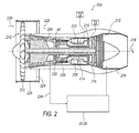
- Figure 2 illustrates a gas turbine engine 200, which includes a fan 202, a low pressure compressor and a high pressure compressor, 204 and 206, a combustor 208, and a high pressure turbine and low pressure turbine, 210 and 212, respectively.
- the high pressure compressor 206 is connected to a first rotor shaft 214 while the low pressure compressor 204 is connected to a second rotor shaft 216.
- the shafts extend axially and are parallel to a longitudinal center line axis 218.
- Ambient air 220 enters the fan 202 and is directed across a fan rotor 222 in an annular duct 224, which in part is circumscribed by fan case 226.
- Bypass airflow 228 provides engine thrust while a primary gas stream 230 is directed to a combustor 232 and the high pressure turbine 210.
- First and second rotor shafts 214, 216 are coupled, respectively, to first and second power circuits 14, 16, as illustrated in Figure 1 .
- first and second power circuits 14, 16 are configured to split power between motor/generators 20, 36 so that each provides a portion of the power demand.
- a power sharing/transfer arrangement between motor/generators 20, 36 provides the platform power demand, and includes a capability to provide power to one of the shafts 214, 216, as necessary.
- Such arrangement also provides an ability to optimize load shedding and a demand side management of the power requirement.
- life and performance considerations may be taken into account in real-time and optimized to actively seek and obtain performance optima while equipment is in operation.
- the present disclosure contemplates diverting a fraction of the bleed air flow 234 through the gas turbine engine 200 for use in cooling either or both of the motor/generators 20,36. It may be controlled by the thermal management system 26, 42 or may have an independent control system. In one embodiment it is contemplated that the bleed air flow 234 may be returned to the nacelle 236 after use by the generator 20, 36. It should be understood that the bleed air flow 234 could be taken from any number of locations within the gas turbine engine 200 and similarly be exhausted in a variety of locations or even exhausted externally.
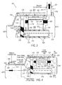
- FIG. 3 illustrates an embodiment of a generator assembly 300 incorporating the controlled air cooling amplifier.
- the generator assembly 300 includes a generator housing 302 containing a rotor assembly 304, a set of rotor windings 306, a stator assembly 308, an exciter stator 310 and an exciter rotor assembly 312.
- An input dive shaft 314 passes through the generator assembly 300 along a generator centerline 316.
- An ejector tube 318 is mounted to and in communication with the interior of the generator housing 302.
- the ejector tube 318 includes at least one fluid entrainment feature 320. Fluid entrainment features 320 utilize a small amount of high pressure air to accelerate a large volume of lower pressure air utilizing known fluid dynamics principles such as the Coanda effect or the Venturi effect.
- the high pressure bleed air 234 is diverted into the fluid entrainment feature 320 which in turn generates a cooling air flow 322 throughout the generator housing 302.
- the fluid may also pass thru rotor 304, in passages between rotor windings.
- the fluid entrainment features 320 is located approximate a cooling air outlet end 324 of the generator housing 302 opposite a cooling air inlet end 326. This effectively pulls the cooling air flow 322 though the generator housing 302.
- the generator assembly 300 additionally includes a variety of features that facilitate the passage of and disperse the cooling air flow 322 within the generator housing 302.
- the input drive shaft 314 is preferably a hollow drive shaft including a plurality of shaft apertures 328 positioned along its length within the generator housing 302. This allows the cooling air flow 322 to be pulled into the generator housing 302 through the input drive shaft 314 and dispersed radially outward to cool the various generator components.
- the shaft apertures 328 may be formed in a variety of fashions, in one embodiment it is contemplated that they are configured on an angle relative to the generator centerline 316 such that the spinning of the input drive shaft 314 serves to motivate the cooling air flow 322 radially outward.
- the exciter rotor assembly 312 includes a plurality of rotor slots 330 formed therein to facilitate the movement of the cooling air flow 322 into and through the generator housing 302.
- the rotor slots 330 may also be orientated on an angle relative to the generator centerline 316 such that the rotation of the exciter rotor assembly 312 assists in moving the cooling air flow 322 into the interior of the generator housing.
- the generator housing 302 itself is contemplated to include a plurality of generator housing apertures 332 formed therein. The generator housing apertures 322 allow cooling air flow 322 to be brought in from the exterior of the generator housing 302.
- the generator housing apertures 332 allow a portion of the air from the cooling air inlet end 326 to be diverted to the exterior of the generator housing 302 prior to being pulled inside for cooling.
- a plurality of air guide baffles 334 may be positioned throughout the generator housing 302 to assist in guiding the cooling air flow 322 past critical components.
- Figure 4 illustrates an alternate embodiment of the generator assembly 300 wherein the fluid entrainment feature 320.
- the fluid entrainment feature 320 includes a pressurized annular chamber 336 with a controllable chamber flow guide 338 to produce the Coanda effect.
- the controllable flow guide 338 allows the amount of amplified cooling air 322 and resulting thermal cooling of the generator 300 to be precisely controlled.
- the fluid entrainment feature 320 is mounted to the generator housing 302 proximate to the cooling air inlet end 326. This allows the cooling air flow 322 to be actively pushed through the generator housing 302 rather than pulled.
- FIG. 5 illustrates a third embodiment of the generator assembly 300.
- the fluid entrainment features 320 and optional ejector tube 318 are positioned radially outward of the generator housing 302.
- a housing flow guide 340 is in communication with both the ejector tube 318 and the generator housing 302 such that the cooling air flow 322 is pulled radially outward therefrom.
- the cooling air flow 322 may be pulled radially outward from the input drive shaft 314 through the shaft apertures 328 and continue in a primarily radial direction until exiting the generator housing 302. This allows a unique pathway for the cooling air flow 322 and allows individual components to be cooled independently from neighboring components.
- the shaft apertures 328 may be positioned and sized to increase the cooling air flow 322 to components most in need of thermal management.
- the fluid entrainment feature 320 allows a modest pressurized bleed airflow 234 to be amplified into a high volume cooling air flow 322.
- the cooling air flow 322 may be controlled to provide constant mass air flow when used at altitude where air density varies. This provides a significant advantage over methodologies attempting to increase fan speed.
- this disclosure eliminates the need for a fan or fan shaft which reduces components and weight simultaneously. It should be understood, that the various features of each disclosed embodiment may be combined in a variety of fashions that would be understood to one skilled in the art in light of the present disclosure.
- Computing devices such as system 10 generally include computer-executable instructions such as the instructions of the system controller 18, where the instructions may be executable by one or more computing devices such as those listed above.
- Computer-executable instructions may be compiled or interpreted from computer programs created using a variety of programming languages and/or technologies, including, without limitation, and either alone or in combination, JavaTM, C, C++, C#, Objective C, Visual Basic, Java Script, Perl, etc.
- a processor e.g., a microprocessor
- receives instructions e.g., from a memory, a computer-readable medium, etc., and executes these instructions, thereby performing one or more processes, including one or more of the processes described herein.
- Such instructions and other data may be stored and transmitted using a variety of computer-readable media.
- a computer-readable medium includes any non-transitory (e.g., tangible) medium that participates in providing data (e.g., instructions) that may be read by a computer (e.g., by a processor of a computer).
- a medium may take many forms, including, but not limited to, non-volatile media and volatile media.
- Non-volatile media may include, for example, optical or magnetic disks and other persistent memory.
- Volatile media may include, for example, dynamic random access memory (DRAM), which typically constitutes a main memory.
- Such instructions may be transmitted by one or more transmission media, including coaxial cables, copper wire and fiber optics, including the wires that comprise a system bus coupled to a processor of a computer.
- Computer-readable media include, for example, a floppy disk, a flexible disk, hard disk, magnetic tape, any other magnetic medium, a CD-ROM, DVD, any other optical medium, punch cards, paper tape, any other physical medium with patterns of holes, a RAM, a PROM, an EPROM, a FLASH-EEPROM, any other memory chip or cartridge, or any other medium from which a computer can read.
- Databases, data repositories or other data stores described herein may include various kinds of mechanisms for storing, accessing, and retrieving various kinds of data, including a hierarchical database, a set of files in a file system, an application database in a proprietary format, a relational database management system (RDBMS), etc.
- Each such data store is generally included within a computing device employing a computer operating system such as one of those mentioned above, and are accessed via a network in any one or more of a variety of manners.
- a file system may be accessible from a computer operating system, and may include files stored in various formats.
- An RDBMS generally employs the Structured Query Language (SQL) in addition to a language for creating, storing, editing, and executing stored procedures, such as the PL/SQL language mentioned above.
- SQL Structured Query Language
- system elements may be implemented as computer-readable instructions (e.g., software) on one or more computing devices (e.g., servers, personal computers, etc.), stored on computer readable media associated therewith (e.g., disks, memories, etc.).
- a computer program product may comprise such instructions stored on computer readable media for carrying out the functions described herein.
Landscapes
- Engineering & Computer Science (AREA)
- Mechanical Engineering (AREA)
- General Engineering & Computer Science (AREA)
- Power Engineering (AREA)
- Chemical & Material Sciences (AREA)
- Combustion & Propulsion (AREA)
- Motor Or Generator Cooling System (AREA)
Abstract
Description
- This application claims priority to
U.S. Provisional Patent Application No. 61/976,801, filed April 8, 2014 - An improved integrated design and control of a gas turbine is disclosed. More particularly, performance and efficiency are improved by optimizing the thermal control of the generator. The improvements are applicable to turbines used for propulsive power in marine, land, air, and underwater applications, as examples.
- It has become increasingly desirable to improve the overall system design and operation of gas turbines. In a system having a typical gas turbine engine, electrical power is extracted via an electrical generator to supply electrical power to control systems, actuators, weapons systems, climate control systems, and the like. Electrical storage, such as a battery, is typically provided to operate such systems when the gas turbine engine is not running or to provide power for starting the gas turbine engine. In some known gas turbine engines, the gas turbine engine includes a high pressure shaft and a lower pressure shaft, and the electrical generator is coupled to one of the high and low pressure shafts.
- The electrical generator commonly generates thermal energy when in operation. It is important to actively cool the electrical generator during operation in order to ensure proper operation as well as extend the lifespan of the generator. This is commonly accomplished through the use of a fan attached to the generator shaft. The fan adds undesirable weight and complexity to the generator. In addition, when the generator is operating at altitude in an aircraft there becomes a reduction in air density. This results in a reduction in air-flow, which in turn reduces cooling. Increasing fan velocity may be utilized to partially address these losses, but is not always efficient or practical.
- Overcoming these concerns would be desirable, could improve generator efficiency, and could save the industry substantial resources.
- According to the present disclosure, there is provided a generator system, as set forth in the appended claims
- While the claims are not limited to a specific illustration, an appreciation of the various aspects is best gained through a discussion of various examples thereof. Referring now to the drawings, exemplary illustrations are shown in detail. Although the drawings represent the illustrations, the drawings are not necessarily to scale and certain features may be exaggerated to better illustrate and explain an innovative aspect of an example. Further, the exemplary illustrations described herein are not intended to be exhaustive or otherwise limiting or restricted to the precise form and configuration shown in the drawings and disclosed in the following detailed description. Exemplary illustrations are described in detail by referring to the drawings as follows:
-
FIG. 1 is a schematic illustration of an electrical system coupled to a gas turbine engine, according to one example; -
FIG. 2 illustrates an exemplary gas turbine engine that incorporates the electrical system illustrated inFIG. 1 ; -
FIG. 3 illustrates an embodiment of a generator assembly incorporating a controlled air cooling amplifier; -
FIG. 4 illustrates a second embodiment of a generator assembly incorporating a controlled air cooling amplifier; and -
FIG. 5 illustrates a third embodiment of a generator assembly incorporating a controlled air cooling amplifier. - An exemplary gas turbine engine and schematic of an electrical system coupled thereto are described herein and are shown in the attached drawings. The electrical system includes at least two generator circuits, one coupled to a high pressure portion of a gas turbine engine and the other coupled to a low pressure portion of the gas turbine engine.
-
Figure 1 illustrates anelectrical system 10 in which a power plant orengine 12, such as a gas turbine engine, provides electrical power to afirst power circuit 14 and asecond power circuit 16. Asystem controller 18 is coupled toengine 12 and also to first andsecond circuits First power circuit 14 includes a motor/generator 20 and a General Control Unit (GCU) 22 coupled thereto. GCU 22 is also coupled to other components withinfirst power circuit 14, such as a health monitoring andprognostics system 24, athermal management system 26, and a power conversion/distribution system 28.First power circuit 14 also includes anenergy storage system 30, anexpansion module 32, and application electrical load(s) 34.System controller 18 is configured to regulate power flow (such as electrical currents and voltages within system 10) to provide power to various electrical busses. The power may be DC, AC, or conversion therebetween.System controller 18 may also be configured to execute computer program instructions to control the operation ofengine 12, including fuel flow, or the position of any variable geometry systems (e.g., from the flight control system of an aircraft or from a steering system of a ship). - Health monitoring and
prognostics system 24 is generally a unit that monitors the health of system components, and may be used to estimate component life based on sensor feedback received from components withinengine 12.Thermal management system 26 includes pumps, expansion valves, and the like, as well as a controller, to provide coolant for the purposes of climate control, and other system operations. Power conversion/distribution system 28 receives electrical power from motor/generator 20 viaGCU 22, and converts the power to a more useable form such as a DC voltage for storage inenergy storage system 30,expansion module 32, and application electrical load(s) 34. Theenergy storage system 30 may include a battery or other energy storage system.Energy storage system 30 stores energy for providing power whenengine 12 is not running (i.e., not generating power), but also to provide power to motor/generator 20 to provide starting power to engine 12 during startup.Expansion module 32 and applicationelectrical load 34 represent additional electrical components that receive power from power conversion/distribution system 28. -
Second power circuit 16 similarly includes a motor/generator 36 and aGCU 38 coupled thereto. GCU 38 is also coupled to other components withinsecond power circuit 16, such as a health monitoring andprognostics system 40, athermal management system 42, and a power conversion/distribution system 44.Second power circuit 16 also includes anenergy storage system 46, anexpansion module 48, and application electrical load(s) 50. The components 36-50 ofsecond power circuit 16 are similarly arranged as described with respect tofirst power circuit 14. Additionally, in one exampleelectrical system 10 includes one or more additional motor/generators 52 and correspondingGCUs 54 as well, which may be coupled to a gas turbine engine as will be further described. Thus, thesystem 10 is modular and flexible in that it may be expanded to include a number N of motor/generators based on contemplated operating conditions. -
Figure 2 illustrates agas turbine engine 200, which includes afan 202, a low pressure compressor and a high pressure compressor, 204 and 206, acombustor 208, and a high pressure turbine and low pressure turbine, 210 and 212, respectively. Thehigh pressure compressor 206 is connected to afirst rotor shaft 214 while thelow pressure compressor 204 is connected to asecond rotor shaft 216. The shafts extend axially and are parallel to a longitudinalcenter line axis 218.Ambient air 220 enters thefan 202 and is directed across afan rotor 222 in anannular duct 224, which in part is circumscribed byfan case 226. Bypassairflow 228 provides engine thrust while aprimary gas stream 230 is directed to acombustor 232 and thehigh pressure turbine 210. - First and
second rotor shafts second power circuits Figure 1 . Thus, first andsecond power circuits generators generators shafts - The present disclosure contemplates diverting a fraction of the
bleed air flow 234 through thegas turbine engine 200 for use in cooling either or both of the motor/generators thermal management system bleed air flow 234 may be returned to thenacelle 236 after use by thegenerator bleed air flow 234 could be taken from any number of locations within thegas turbine engine 200 and similarly be exhausted in a variety of locations or even exhausted externally. -
Figure 3 illustrates an embodiment of agenerator assembly 300 incorporating the controlled air cooling amplifier. Thegenerator assembly 300 includes agenerator housing 302 containing arotor assembly 304, a set ofrotor windings 306, astator assembly 308, anexciter stator 310 and anexciter rotor assembly 312. Aninput dive shaft 314 passes through thegenerator assembly 300 along agenerator centerline 316. Anejector tube 318 is mounted to and in communication with the interior of thegenerator housing 302. Theejector tube 318 includes at least onefluid entrainment feature 320. Fluid entrainment features 320 utilize a small amount of high pressure air to accelerate a large volume of lower pressure air utilizing known fluid dynamics principles such as the Coanda effect or the Venturi effect. Although the present embodiment contemplates the use of a Coanda effect amplifier, one skilled in the art would recognize in light of this disclosure a variety of alternate features. The highpressure bleed air 234 is diverted into thefluid entrainment feature 320 which in turn generates a coolingair flow 322 throughout thegenerator housing 302. The fluid may also pass thrurotor 304, in passages between rotor windings. In the present embodiment, the fluid entrainment features 320 is located approximate a coolingair outlet end 324 of thegenerator housing 302 opposite a coolingair inlet end 326. This effectively pulls the coolingair flow 322 though thegenerator housing 302. - The
generator assembly 300 additionally includes a variety of features that facilitate the passage of and disperse the coolingair flow 322 within thegenerator housing 302. Theinput drive shaft 314 is preferably a hollow drive shaft including a plurality ofshaft apertures 328 positioned along its length within thegenerator housing 302. This allows the coolingair flow 322 to be pulled into thegenerator housing 302 through theinput drive shaft 314 and dispersed radially outward to cool the various generator components. Although theshaft apertures 328 may be formed in a variety of fashions, in one embodiment it is contemplated that they are configured on an angle relative to thegenerator centerline 316 such that the spinning of theinput drive shaft 314 serves to motivate the coolingair flow 322 radially outward. - Similarly, it is contemplated that the
exciter rotor assembly 312 includes a plurality ofrotor slots 330 formed therein to facilitate the movement of the coolingair flow 322 into and through thegenerator housing 302. Therotor slots 330 may also be orientated on an angle relative to thegenerator centerline 316 such that the rotation of theexciter rotor assembly 312 assists in moving the coolingair flow 322 into the interior of the generator housing. Finally, thegenerator housing 302 itself is contemplated to include a plurality ofgenerator housing apertures 332 formed therein. Thegenerator housing apertures 322 allow coolingair flow 322 to be brought in from the exterior of thegenerator housing 302. In addition when utilizes in combination with agenerator shell 334 surrounding thegenerator housing 302, thegenerator housing apertures 332 allow a portion of the air from the coolingair inlet end 326 to be diverted to the exterior of thegenerator housing 302 prior to being pulled inside for cooling. Finally, a plurality of air guide baffles 334 may be positioned throughout thegenerator housing 302 to assist in guiding the coolingair flow 322 past critical components. Although the present embodiment has been described as including anejector tube 318, it is contemplated that thefluid entrainment feature 320 may be incorporated directly into thegenerator housing 302. -
Figure 4 illustrates an alternate embodiment of thegenerator assembly 300 wherein thefluid entrainment feature 320. Thefluid entrainment feature 320 includes a pressurizedannular chamber 336 with a controllablechamber flow guide 338 to produce the Coanda effect. Thecontrollable flow guide 338 allows the amount of amplifiedcooling air 322 and resulting thermal cooling of thegenerator 300 to be precisely controlled. In this embodiment, thefluid entrainment feature 320 is mounted to thegenerator housing 302 proximate to the coolingair inlet end 326. This allows the coolingair flow 322 to be actively pushed through thegenerator housing 302 rather than pulled. -
Figure 5 illustrates a third embodiment of thegenerator assembly 300. In this embodiment, the fluid entrainment features 320 andoptional ejector tube 318 are positioned radially outward of thegenerator housing 302. Ahousing flow guide 340 is in communication with both theejector tube 318 and thegenerator housing 302 such that the coolingair flow 322 is pulled radially outward therefrom. In this embodiment, the coolingair flow 322 may be pulled radially outward from theinput drive shaft 314 through theshaft apertures 328 and continue in a primarily radial direction until exiting thegenerator housing 302. This allows a unique pathway for the coolingair flow 322 and allows individual components to be cooled independently from neighboring components. It is further contemplated that theshaft apertures 328 may be positioned and sized to increase the coolingair flow 322 to components most in need of thermal management. - In each embodiment, the
fluid entrainment feature 320 allows a modestpressurized bleed airflow 234 to be amplified into a high volumecooling air flow 322. In addition, the coolingair flow 322 may be controlled to provide constant mass air flow when used at altitude where air density varies. This provides a significant advantage over methodologies attempting to increase fan speed. Furthermore, this disclosure eliminates the need for a fan or fan shaft which reduces components and weight simultaneously. It should be understood, that the various features of each disclosed embodiment may be combined in a variety of fashions that would be understood to one skilled in the art in light of the present disclosure. - Computing devices such as
system 10 generally include computer-executable instructions such as the instructions of thesystem controller 18, where the instructions may be executable by one or more computing devices such as those listed above. Computer-executable instructions may be compiled or interpreted from computer programs created using a variety of programming languages and/or technologies, including, without limitation, and either alone or in combination, Java™, C, C++, C#, Objective C, Visual Basic, Java Script, Perl, etc. In general, a processor (e.g., a microprocessor) receives instructions, e.g., from a memory, a computer-readable medium, etc., and executes these instructions, thereby performing one or more processes, including one or more of the processes described herein. Such instructions and other data may be stored and transmitted using a variety of computer-readable media. - Aspects of the disclosure will be described below by numbered clauses:
- 1. A gas turbine generator cooling system (300) comprising:
- a gas turbine engine (200) generating bleed air (234); and
- a generator (20, 36) including a generator housing (302) and at least one fluid entrainment feature (320), said at least one fluid entrainment feature (320) utilizing a fraction of said bleed air (234) to generate a cooling air (322) flow through said generator housing (302).
- 2. The gas turbine generator cooling system (300) of
clause 1, wherein said at least one fluid entrainment feature (320) comprises a Coanda effect feature. - 3. The gas turbine generator cooling system (300) of
clauses - a hollow generator shaft (314) including a plurality of shaft apertures (328) positioned within said generator housing (302);
- wherein at least a portion of said cooling air (322) flow is moved into said hollow generator shaft (314) and dispersed into said generator housing (302) through said plurality of shaft apertures (328).
- 4. The gas turbine generator cooling system (300) of
clauses 1 to 3, wherein said generator (20, 36) further comprises:- at least one exciter rotor (304) including a plurality of rotor slots (330);
- wherein at least a portion of said cooling air (322) flow is moved into said generator housing (302) through said plurality of rotor slots (330).
- 5. The gas turbine generator cooling system (300) of
clauses 1 to 4, wherein said plurality of rotor slots (330) are angled relative to a generator centerline (316). - 6. The gas turbine generator cooling system (300) of
clauses 1 to 5, wherein said generator housing (302) further comprises:- a plurality of generator housing apertures (332) formed along its length;
- wherein at least a portion of said cooling air (322) flow is moved into said generator housing (302) through said plurality of generator housing apertures (332).
- 7. The gas turbine generator cooling system (300) of
clauses 1 to 6, wherein said generator housing (302) comprises:- a cooling air inlet end (326); and
- a cooling air outlet end (324);
- wherein said at least one fluid entrainment feature (320) is positioned proximate to said cooling air outlet end (324) such that said cooling air flow is pulled through said generator housing (302).
- 8. The gas turbine generator cooling system (300) of
clauses 1 to 7, wherein said generator housing (302) comprises:- a cooling air inlet end (326); and
- a cooling air outlet end (324);
- wherein said at least one fluid entrainment feature (320) is positioned proximate to said cooling air inlet end (326) such that said cooling air flow (322) is pushed through said generator housing (302).
- 9. The gas turbine generator cooling system (300) of clause 3, wherein said generator housing (302) comprises:
- a plurality of generator housing apertures (332) formed along its length;
- wherein said at least one fluid entrainment feature (320) is positioned radially outward of said generator housing (302) such that said cooling air flow (322) is pulled through said generator housing (302) in an outward radial direction.
- 10. The gas turbine generator cooling system (300) of
clauses 1 to 9, further comprising:- at least one air guide baffle (334) positioned within said generator housing (302), said at least one air guide baffle (334) configured to route said cooling air flow (322) relative to said generator housing (302).
- 11. A generator cooling system (300) comprising:
- a generator (20, 36) including a generator housing (302) and at least one fluid entrainment feature (320), said at least one fluid entrainment feature (320) generating a cooling air flow (322) through said generator housing (302).
- 12. The generator cooling system (300) of clause 11, wherein said at least one fluid entrainment feature (320) comprises a Coanda effect feature.
- 13. The generator cooling system (300) of clauses 11 to 12, further comprising:
- a hollow generator shaft (314) including a plurality of shaft apertures (328) positioned within said generator housing (302);
- wherein at least a portion of said cooling air flow (322) is moved into said hollow generator shaft (314) and dispersed into said generator housing (302) through said plurality of shaft apertures (328).
- 14. The generator cooling system (300) of clauses 11 to 13, further comprising:
- at least one exciter rotor (312) including a plurality of rotor slots (330);
- wherein at least a portion of said cooling air flow (322) is moved into said generator housing (302) through said plurality of rotor slots (330).
- 15. The generator cooling system (300) of clauses 11 to 14, further comprising:
- at least one air guide baffle (334) positioned within said generator housing (302), said at least one air guide baffle (334) configured to route said cooling air flow (322) through said generator housing (302).
- 16. A method of cooling a gas turbine generator (20, 36) comprising:
- bleeding air (234) from the compressor (204) of a gas turbine engine (200) ;
- directing a portion of said bleed air into at least one fluid entrainment feature (320) in communication with a generator housing (302) of a generator (20, 36); and
- generating a cooling air flow (322) through said generator housing (302) using said at least one fluid entrainment feature (320).
- 17. The method of cooling a gas turbine generator (20, 36) of
clause 16, wherein said at least one fluid entrainment feature (320) comprises a Coanda effect feature. - 18. The method of cooling a gas turbine generator (20, 36) of
clauses 16 to 17, further comprising:- directing said cooling air flow (322) through a hollow generator shaft (314), said hollow generator shaft (314) including a plurality of shaft apertures (328) positioned within said generator housing (302); and
- dispersing at least a portion of said cooling air flow (322) into said generator housing (302) through said plurality of shaft apertures (328).
- 19. The method of cooling a gas turbine generator (20, 36) of
clauses 16 to 18, further comprising:- directing said cooling air flow (322) through a plurality of rotor slots (330) formed in at least one rotor (312); and
- dispersing at least a portion of said cooling air flow (322) into said generator housing (302) through said plurality of rotor slots (330).
- 20. The method of cooling a gas turbine generator (20, 36) of
clauses 16 to 19, further comprising:- directing said cooling air flow (322) through a plurality of generator housing apertures (328) formed in said generator housing (302); and
- pulling at least a portion of said cooling air flow (322) outwardly through said generator housing (302) by positioning said at least one fluid entrainment feature (320) radially outward of said generator housing (302).
- A computer-readable medium (also referred to as a processor-readable medium) includes any non-transitory (e.g., tangible) medium that participates in providing data (e.g., instructions) that may be read by a computer (e.g., by a processor of a computer). Such a medium may take many forms, including, but not limited to, non-volatile media and volatile media. Non-volatile media may include, for example, optical or magnetic disks and other persistent memory. Volatile media may include, for example, dynamic random access memory (DRAM), which typically constitutes a main memory. Such instructions may be transmitted by one or more transmission media, including coaxial cables, copper wire and fiber optics, including the wires that comprise a system bus coupled to a processor of a computer. Common forms of computer-readable media include, for example, a floppy disk, a flexible disk, hard disk, magnetic tape, any other magnetic medium, a CD-ROM, DVD, any other optical medium, punch cards, paper tape, any other physical medium with patterns of holes, a RAM, a PROM, an EPROM, a FLASH-EEPROM, any other memory chip or cartridge, or any other medium from which a computer can read.
- Databases, data repositories or other data stores described herein may include various kinds of mechanisms for storing, accessing, and retrieving various kinds of data, including a hierarchical database, a set of files in a file system, an application database in a proprietary format, a relational database management system (RDBMS), etc. Each such data store is generally included within a computing device employing a computer operating system such as one of those mentioned above, and are accessed via a network in any one or more of a variety of manners. A file system may be accessible from a computer operating system, and may include files stored in various formats. An RDBMS generally employs the Structured Query Language (SQL) in addition to a language for creating, storing, editing, and executing stored procedures, such as the PL/SQL language mentioned above.
- In some examples, system elements may be implemented as computer-readable instructions (e.g., software) on one or more computing devices (e.g., servers, personal computers, etc.), stored on computer readable media associated therewith (e.g., disks, memories, etc.). A computer program product may comprise such instructions stored on computer readable media for carrying out the functions described herein.
- With regard to the processes, systems, methods, heuristics, etc. described herein, it should be understood that, although the steps of such processes, etc. have been described as occurring according to a certain ordered sequence, such processes could be practiced with the described steps performed in an order other than the order described herein. It further should be understood that certain steps could be performed simultaneously, that other steps could be added, or that certain steps described herein could be omitted. In other words, the descriptions of processes herein are provided for the purpose of illustrating certain embodiments, and should in no way be construed so as to limit the claims.
- All terms used in the claims are intended to be given their broadest reasonable constructions and their ordinary meanings as understood by those knowledgeable in the technologies described herein unless an explicit indication to the contrary in made herein. In particular, use of the singular articles such as "a," "the," "said," etc. should be read to recite one or more of the indicated elements unless a claim recites an explicit limitation to the contrary.
Claims (15)
- A gas turbine generator cooling system (300) comprising:a gas turbine engine (200) generating bleed air (234); anda generator (20, 36) including a generator housing (302) and at least one fluid entrainment feature (320), said at least one fluid entrainment feature (320) utilizing a fraction of said bleed air (234) to generate a cooling air flow (322) through said generator housing (302).
- A gas turbine generator cooling system (300) as claimed in claim 1, wherein said at least one fluid entrainment feature (320) comprises a Coanda effect feature.
- A gas turbine generator cooling system (300) as claimed in claims 1 and 2, wherein said generator (20, 36) further comprises:a hollow generator shaft (314) including a plurality of shaft apertures (328) positioned within said generator housing (302);wherein at least a portion of said cooling air flow (322) is moved into said hollow generator shaft (314) and dispersed into said generator housing (302) through said plurality of shaft apertures (328).
- A gas turbine generator cooling system (300) as described in claims 1 to 3, wherein said generator (20,36) further comprises:at least one exciter rotor (304) including a plurality of rotor slots (330);wherein at least a portion of said cooling air flow (322) is moved into said generator housing (302) through said plurality of rotor slots (330).
- A gas turbine generator cooling system (300) as described in claims 1 to 4, wherein said plurality of rotor slots (330) are angled relative to a generator centerline (316).
- A gas turbine generator cooling system (300) as described in claims 1 to 5, wherein said generator housing (302) further comprises:a plurality of generator housing apertures (332) formed along its length;wherein at least a portion of said cooling air flow (322) is moved into said generator housing (302) through said plurality of generator housing apertures (332).
- A gas turbine generator cooling system (300) as described in claims 1 to 6, wherein said generator housing (302) comprises:a cooling air inlet end (326); anda cooling air outlet end (324);wherein said at least one fluid entrainment feature (320) is positioned proximate to said cooling air outlet end (324) such that said cooling air flow is pulled through said generator housing (302).
- A gas turbine generator cooling system (300) as described in claims 1 to 7, wherein said generator housing (302) comprises:a cooling air inlet end (326); anda cooling air outlet end (324);wherein said at least one fluid entrainment feature (320) is positioned proximate to said cooling air inlet end (326) such that said cooling air flow (322) is pushed through said generator housing (302).
- A gas turbine generator cooling system (300) as described in claim 3, wherein said generator housing (302) comprises:a plurality of generator housing apertures (332) formed along its length;wherein said at least one fluid entrainment feature (320) is positioned radially outward of said generator housing (302) such that said cooling air flow (322) is pulled through said generator housing (302) in an outward radial direction.
- A gas turbine generator cooling system (300) as described in claims 1 to 9, further comprising:at least one air guide baffle (334) positioned within said generator housing (302), said at least one air guide baffle (334) configured to route said cooling air flow (322) relative to said generator housing (302).
- A generator cooling system (300) comprising:a generator (20, 36) including a generator housing (302) and at least one fluid entrainment feature (320), said at least one fluid entrainment feature (320) generating a cooling air flow (322) through said generator housing (302).
- A generator cooling system (300) as claimed in claim 11, wherein said at least one fluid entrainment feature (320) comprises a Coanda effect feature.
- A generator cooling system (300) as claimed in claims 11 to 12, further comprising:a hollow generator shaft (314) including a plurality of shaft apertures (328) positioned within said generator housing (302);wherein at least a portion of said cooling air flow (322) is moved into said hollow generator shaft (314) and dispersed into said generator housing (302) through said plurality of shaft apertures (328).
- A generator cooling system (300) as described in claims 11 to 13, further comprising:at least one exciter rotor (312) including a plurality of rotor slots (330);wherein at least a portion of said cooling air flow (322) is moved into said generator housing (302) through said plurality of rotor slots (330).
- A generator cooling system (300) as described in claims 11 to 14, further comprising:at least one air guide baffle (334) positioned within said generator housing (302), said at least one air guide baffle (334) configured to route said cooling air flow (322) through said generator housing (302).
Applications Claiming Priority (1)
| Application Number | Priority Date | Filing Date | Title |
|---|---|---|---|
| US201461976801P | 2014-04-08 | 2014-04-08 |
Publications (2)
| Publication Number | Publication Date |
|---|---|
| EP2930314A1 true EP2930314A1 (en) | 2015-10-14 |
| EP2930314B1 EP2930314B1 (en) | 2022-06-08 |
Family
ID=52807695
Family Applications (1)
| Application Number | Title | Priority Date | Filing Date |
|---|---|---|---|
| EP15162313.9A Active EP2930314B1 (en) | 2014-04-08 | 2015-04-02 | Generator with controlled air cooling amplifier |
Country Status (2)
| Country | Link |
|---|---|
| US (1) | US9570958B2 (en) |
| EP (1) | EP2930314B1 (en) |
Families Citing this family (8)
| Publication number | Priority date | Publication date | Assignee | Title |
|---|---|---|---|---|
| FR3059363B1 (en) * | 2016-11-25 | 2019-04-05 | Turbotech | TURBOMACHINE, IN PARTICULAR TURBOGENERATOR AND EXCHANGER FOR SUCH A TURBOMACHINE |
| DE102017212798A1 (en) | 2017-07-26 | 2019-01-31 | Siemens Aktiengesellschaft | Electric motor with cooling device |
| WO2021192162A1 (en) * | 2020-03-26 | 2021-09-30 | 三菱重工エンジン&ターボチャージャ株式会社 | Rotary machine |
| PL435035A1 (en) * | 2020-08-20 | 2022-02-21 | General Electric Company Polska Spółka Z Ograniczoną Odpowiedzialnością | Gas turbine engines containing embedded electrical machines and associated cooling systems |
| JP7547292B2 (en) * | 2021-08-10 | 2024-09-09 | 本田技研工業株式会社 | Combined Power System |
| FR3129375B1 (en) * | 2021-11-25 | 2026-01-30 | Safran | ELECTRICAL POWER CONVERSION AND TRANSPORT SYSTEM FOR THE INTERNAL HYBRIDIZATION OF AN AIRCRAFT TURBOMACHINE |
| CN114109590B (en) * | 2021-11-25 | 2022-09-13 | 镇江康驰机电设备有限公司 | Generator set with surrounding type heat dissipation function and using method thereof |
| CN119778098A (en) * | 2024-12-04 | 2025-04-08 | 南京航空航天大学 | Air jet type cooling device for embedded high-temperature high-speed motor of aero-engine |
Citations (5)
| Publication number | Priority date | Publication date | Assignee | Title |
|---|---|---|---|---|
| JPH0382356A (en) * | 1989-08-22 | 1991-04-08 | Fanuc Ltd | Cooling structure of motor |
| WO2002027150A1 (en) * | 2000-09-29 | 2002-04-04 | Turbec Ab | Emergency system |
| JP2005012891A (en) * | 2003-06-18 | 2005-01-13 | Toyota Central Res & Dev Lab Inc | Axial permanent magnet motor |
| DE102006043550A1 (en) * | 2006-02-06 | 2007-08-30 | Franz Kessler Gmbh | Motor e.g. three-phase alternating current synchronous motor, milling spindle for machine tool, has cooling unit with cooling fluid e.g. cooling air, for cooling motor, and stator housing with fluid and/or air-passage for conveyance of air |
| US20100219638A1 (en) * | 2004-02-14 | 2010-09-02 | Richard Julius Gozdawa | Turbomachinery Electric Generator Arrangement |
Family Cites Families (46)
| Publication number | Priority date | Publication date | Assignee | Title |
|---|---|---|---|---|
| US4046492A (en) | 1976-01-21 | 1977-09-06 | Vortec Corporation | Air flow amplifier |
| US4086757A (en) * | 1976-10-06 | 1978-05-02 | Caterpillar Tractor Co. | Gas turbine cooling system |
| US4474001A (en) * | 1981-04-01 | 1984-10-02 | United Technologies Corporation | Cooling system for the electrical generator of a turbofan gas turbine engine |
| US5048288A (en) * | 1988-12-20 | 1991-09-17 | United Technologies Corporation | Combined turbine stator cooling and turbine tip clearance control |
| US5097660A (en) | 1988-12-28 | 1992-03-24 | Sundstrand Corporation | Coanda effect turbine nozzle vane cooling |
| US5365738A (en) * | 1991-12-26 | 1994-11-22 | Solar Turbines Incorporated | Low emission combustion nozzle for use with a gas turbine engine |
| US5497615A (en) * | 1994-03-21 | 1996-03-12 | Noe; James C. | Gas turbine generator set |
| US6239520B1 (en) * | 2000-04-24 | 2001-05-29 | Capstone Turbine Corporation | Permanent magnet rotor cooling system and method |
| WO2002066324A2 (en) * | 2001-02-16 | 2002-08-29 | Hamilton Sundstrand Corporation | Improved aircraft system architecture |
| US6826910B1 (en) | 2002-01-28 | 2004-12-07 | Mark Richard Easton | Extreme charger with air amplifier |
| US6568203B1 (en) | 2002-05-01 | 2003-05-27 | Honeywell International, Inc. | Aircraft ground support air conditioning unit with cooling turbine bypass |
| US6798079B2 (en) * | 2002-07-11 | 2004-09-28 | Siemens Westinghouse Power Corporation | Turbine power generator including supplemental parallel cooling and related methods |
| US6851267B2 (en) * | 2002-12-18 | 2005-02-08 | Pratt & Whitney Canada Corp. | Compact quick attach starter-generator installation |
| US6968697B2 (en) * | 2003-09-17 | 2005-11-29 | Honeywell International Inc. | Integral compressor housing of gas turbine engines |
| US7152410B2 (en) * | 2004-06-10 | 2006-12-26 | Honeywell International, Inc. | System and method for dumping surge flow into eductor primary nozzle for free turbine |
| US7246482B2 (en) * | 2004-07-16 | 2007-07-24 | Honeywell International, Inc. | Gas turbine engine bleed air power assist system and method |
| FR2891313A1 (en) * | 2005-09-26 | 2007-03-30 | Airbus France Sas | DOUBLE FLOW TURBOMOTEUR HAVING A PRE-COOLER |
| US7654085B2 (en) | 2006-08-28 | 2010-02-02 | Elijah Dumas | System of an induced flow machine |
| EP2066890B1 (en) * | 2006-10-12 | 2010-12-15 | United Technologies Corporation | Modulating flow through gas turbine engine cooling system |
| US7862293B2 (en) * | 2007-05-03 | 2011-01-04 | Pratt & Whitney Canada Corp. | Low profile bleed air cooler |
| US8029244B2 (en) | 2007-08-02 | 2011-10-04 | Elijah Dumas | Fluid flow amplifier |
| US7966831B2 (en) * | 2007-08-28 | 2011-06-28 | General Electric Company | Apparatus and method for suppressing dynamic pressure instability in bleed duct |
| US8046989B2 (en) | 2007-11-14 | 2011-11-01 | Paccar Inc | Cooling device for high temperature exhaust |
| US8659185B2 (en) * | 2008-09-29 | 2014-02-25 | General Electric Company | Method and apparatus for an electrical bus leveling unit |
| US8181443B2 (en) * | 2008-12-10 | 2012-05-22 | Pratt & Whitney Canada Corp. | Heat exchanger to cool turbine air cooling flow |
| US20100170262A1 (en) * | 2009-01-06 | 2010-07-08 | Kaslusky Scott F | Aircraft power and thermal management system with electric co-generation |
| US8307662B2 (en) * | 2009-10-15 | 2012-11-13 | General Electric Company | Gas turbine engine temperature modulated cooling flow |
| GB201007063D0 (en) * | 2010-04-28 | 2010-06-09 | Rolls Royce Plc | A gas turbine engine |
| CN102597459B (en) * | 2010-06-03 | 2015-06-17 | 松下电器产业株式会社 | Gas turbine system |
| US20120192578A1 (en) * | 2011-01-27 | 2012-08-02 | Hamilton Sundstrand Corporation | Gas turbine bleed ecs cooling |
| DE102011076452B4 (en) * | 2011-05-25 | 2016-10-13 | Siemens Aktiengesellschaft | Housing unit and electrical machine with a housing unit |
| US9022737B2 (en) * | 2011-08-08 | 2015-05-05 | United Technologies Corporation | Airfoil including trench with contoured surface |
| US9267434B2 (en) * | 2012-01-29 | 2016-02-23 | United Technologies Corporation | Heat exchanger |
| US9316153B2 (en) * | 2013-01-22 | 2016-04-19 | Siemens Energy, Inc. | Purge and cooling air for an exhaust section of a gas turbine assembly |
| EP2767675A1 (en) * | 2013-02-15 | 2014-08-20 | Siemens Aktiengesellschaft | Through flow ventilation system for a power generation turbine package |
| WO2015021086A1 (en) * | 2013-08-06 | 2015-02-12 | General Electric Company | Mounting apparatus for low-ductility turbine nozzle |
| WO2015026431A1 (en) * | 2013-08-21 | 2015-02-26 | Hamilton Sundstrand Corporation | Environmental control generator system and apparatus |
| US20160201908A1 (en) * | 2013-08-30 | 2016-07-14 | United Technologies Corporation | Vena contracta swirling dilution passages for gas turbine engine combustor |
| EP3044444B1 (en) * | 2013-09-13 | 2019-11-06 | United Technologies Corporation | Combustor for a gas turbine engine with a sealed liner panel |
| US9540962B2 (en) * | 2014-07-14 | 2017-01-10 | Siemens Energy, Inc. | Power plant air cooled heat exchanger or condenser with pressurized gas entrained cooling liquid mister |
| US10767562B2 (en) * | 2014-12-10 | 2020-09-08 | Pratt & Whitney Canada Corp. | Modulated cooled P3 air for impeller |
| US9771872B2 (en) * | 2014-12-15 | 2017-09-26 | Emerson Process Management Power & Water Solutions, Inc. | Model-based combined cycle power plant load control |
| US10415483B2 (en) * | 2014-12-15 | 2019-09-17 | Jetheat Llc | Method to control the operating temperature of a gas turbine heater |
| US9903666B2 (en) * | 2014-12-17 | 2018-02-27 | Hamilton Sundstrand Corporation | Motor stator cooling with dual coolant two-phase heat exchanger |
| US20160178199A1 (en) * | 2014-12-17 | 2016-06-23 | United Technologies Corporation | Combustor dilution hole active heat transfer control apparatus and system |
| US10041378B2 (en) * | 2015-01-08 | 2018-08-07 | General Electric Company | Systems and methods for adjusting floor pressure levels to improve combined cycle plant startup |
-
2015
- 2015-04-02 EP EP15162313.9A patent/EP2930314B1/en active Active
- 2015-04-06 US US14/679,432 patent/US9570958B2/en active Active
Patent Citations (5)
| Publication number | Priority date | Publication date | Assignee | Title |
|---|---|---|---|---|
| JPH0382356A (en) * | 1989-08-22 | 1991-04-08 | Fanuc Ltd | Cooling structure of motor |
| WO2002027150A1 (en) * | 2000-09-29 | 2002-04-04 | Turbec Ab | Emergency system |
| JP2005012891A (en) * | 2003-06-18 | 2005-01-13 | Toyota Central Res & Dev Lab Inc | Axial permanent magnet motor |
| US20100219638A1 (en) * | 2004-02-14 | 2010-09-02 | Richard Julius Gozdawa | Turbomachinery Electric Generator Arrangement |
| DE102006043550A1 (en) * | 2006-02-06 | 2007-08-30 | Franz Kessler Gmbh | Motor e.g. three-phase alternating current synchronous motor, milling spindle for machine tool, has cooling unit with cooling fluid e.g. cooling air, for cooling motor, and stator housing with fluid and/or air-passage for conveyance of air |
Also Published As
| Publication number | Publication date |
|---|---|
| EP2930314B1 (en) | 2022-06-08 |
| US9570958B2 (en) | 2017-02-14 |
| US20150288253A1 (en) | 2015-10-08 |
Similar Documents
| Publication | Publication Date | Title |
|---|---|---|
| US9570958B2 (en) | Generator with controlled air cooling amplifier | |
| US10436122B2 (en) | Fuel-air ratio control of gas turbine engines | |
| US10583931B2 (en) | System and method for coordinated control of a power system | |
| US11506131B2 (en) | Thermal management system | |
| EP2881563B1 (en) | Integrated electrical power and thermal management system | |
| US11143104B2 (en) | Thermal management system | |
| US9853335B2 (en) | Thermal management of energy storage | |
| US20190010870A1 (en) | Turbine engine thermal management | |
| EP2972620B1 (en) | Integrated health management approach to propulsion control system protection limiting | |
| WO2014143282A1 (en) | Air-oil heat exchangers with minimum bypass flow pressure loss | |
| US11542870B1 (en) | Gas supply system | |
| US10773813B2 (en) | Aircraft with a propulsion unit comprising a fan at the rear of the fuselage | |
| US10641123B1 (en) | Generator cooling impeller and bearing/rotor cooling | |
| CA2905300A1 (en) | Prognostic health management approaches for propulsion control systems | |
| Maas et al. | Pre-design investigation of a propulsion system with compressor electric drive | |
| US20150345389A1 (en) | Multi Stage Air Flow Management | |
| US20230332513A1 (en) | System and method of regulating thermal transport bus pressure | |
| CN120664116A (en) | Hybrid electric thermal management system for aircraft engine | |
| EP4382432B1 (en) | FUEL TANK HEAT DEFLECTION SYSTEM | |
| US11248534B2 (en) | System and method for engine eductor powered by alternate managed air system | |
| CN118358769A (en) | Fuel cooling system | |
| EP4063631A2 (en) | Turbine engine system equipped with a fuel deoxygenation system and turboelectric power system | |
| US12618337B1 (en) | Aircraft powerplant with ventilated cable conduit | |
| US20240110509A1 (en) | Heat exchanger for a gas turbine engine | |
| US20260117702A1 (en) | Thermal management system for open rotor aircraft propulsion system |
Legal Events
| Date | Code | Title | Description |
|---|---|---|---|
| PUAI | Public reference made under article 153(3) epc to a published international application that has entered the european phase |
Free format text: ORIGINAL CODE: 0009012 |
|
| AK | Designated contracting states |
Kind code of ref document: A1 Designated state(s): AL AT BE BG CH CY CZ DE DK EE ES FI FR GB GR HR HU IE IS IT LI LT LU LV MC MK MT NL NO PL PT RO RS SE SI SK SM TR |
|
| AX | Request for extension of the european patent |
Extension state: BA ME |
|
| 17P | Request for examination filed |
Effective date: 20160209 |
|
| RBV | Designated contracting states (corrected) |
Designated state(s): AL AT BE BG CH CY CZ DE DK EE ES FI FR GB GR HR HU IE IS IT LI LT LU LV MC MK MT NL NO PL PT RO RS SE SI SK SM TR |
|
| 17Q | First examination report despatched |
Effective date: 20160405 |
|
| STAA | Information on the status of an ep patent application or granted ep patent |
Free format text: STATUS: EXAMINATION IS IN PROGRESS |
|
| GRAP | Despatch of communication of intention to grant a patent |
Free format text: ORIGINAL CODE: EPIDOSNIGR1 |
|
| STAA | Information on the status of an ep patent application or granted ep patent |
Free format text: STATUS: GRANT OF PATENT IS INTENDED |
|
| INTG | Intention to grant announced |
Effective date: 20211207 |
|
| GRAS | Grant fee paid |
Free format text: ORIGINAL CODE: EPIDOSNIGR3 |
|
| GRAA | (expected) grant |
Free format text: ORIGINAL CODE: 0009210 |
|
| STAA | Information on the status of an ep patent application or granted ep patent |
Free format text: STATUS: THE PATENT HAS BEEN GRANTED |
|
| AK | Designated contracting states |
Kind code of ref document: B1 Designated state(s): AL AT BE BG CH CY CZ DE DK EE ES FI FR GB GR HR HU IE IS IT LI LT LU LV MC MK MT NL NO PL PT RO RS SE SI SK SM TR |
|
| REG | Reference to a national code |
Ref country code: GB Ref legal event code: FG4D |
|
| REG | Reference to a national code |
Ref country code: AT Ref legal event code: REF Ref document number: 1497053 Country of ref document: AT Kind code of ref document: T Effective date: 20220615 Ref country code: CH Ref legal event code: EP |
|
| REG | Reference to a national code |
Ref country code: DE Ref legal event code: R096 Ref document number: 602015079315 Country of ref document: DE |
|
| REG | Reference to a national code |
Ref country code: IE Ref legal event code: FG4D |
|
| REG | Reference to a national code |
Ref country code: LT Ref legal event code: MG9D |
|
| REG | Reference to a national code |
Ref country code: NL Ref legal event code: MP Effective date: 20220608 |
|
| PG25 | Lapsed in a contracting state [announced via postgrant information from national office to epo] |
Ref country code: SE Free format text: LAPSE BECAUSE OF FAILURE TO SUBMIT A TRANSLATION OF THE DESCRIPTION OR TO PAY THE FEE WITHIN THE PRESCRIBED TIME-LIMIT Effective date: 20220608 Ref country code: NO Free format text: LAPSE BECAUSE OF FAILURE TO SUBMIT A TRANSLATION OF THE DESCRIPTION OR TO PAY THE FEE WITHIN THE PRESCRIBED TIME-LIMIT Effective date: 20220908 Ref country code: LT Free format text: LAPSE BECAUSE OF FAILURE TO SUBMIT A TRANSLATION OF THE DESCRIPTION OR TO PAY THE FEE WITHIN THE PRESCRIBED TIME-LIMIT Effective date: 20220608 Ref country code: HR Free format text: LAPSE BECAUSE OF FAILURE TO SUBMIT A TRANSLATION OF THE DESCRIPTION OR TO PAY THE FEE WITHIN THE PRESCRIBED TIME-LIMIT Effective date: 20220608 Ref country code: GR Free format text: LAPSE BECAUSE OF FAILURE TO SUBMIT A TRANSLATION OF THE DESCRIPTION OR TO PAY THE FEE WITHIN THE PRESCRIBED TIME-LIMIT Effective date: 20220909 Ref country code: FI Free format text: LAPSE BECAUSE OF FAILURE TO SUBMIT A TRANSLATION OF THE DESCRIPTION OR TO PAY THE FEE WITHIN THE PRESCRIBED TIME-LIMIT Effective date: 20220608 Ref country code: ES Free format text: LAPSE BECAUSE OF FAILURE TO SUBMIT A TRANSLATION OF THE DESCRIPTION OR TO PAY THE FEE WITHIN THE PRESCRIBED TIME-LIMIT Effective date: 20220608 Ref country code: BG Free format text: LAPSE BECAUSE OF FAILURE TO SUBMIT A TRANSLATION OF THE DESCRIPTION OR TO PAY THE FEE WITHIN THE PRESCRIBED TIME-LIMIT Effective date: 20220908 |
|
| REG | Reference to a national code |
Ref country code: AT Ref legal event code: MK05 Ref document number: 1497053 Country of ref document: AT Kind code of ref document: T Effective date: 20220608 |
|
| PG25 | Lapsed in a contracting state [announced via postgrant information from national office to epo] |
Ref country code: RS Free format text: LAPSE BECAUSE OF FAILURE TO SUBMIT A TRANSLATION OF THE DESCRIPTION OR TO PAY THE FEE WITHIN THE PRESCRIBED TIME-LIMIT Effective date: 20220608 Ref country code: LV Free format text: LAPSE BECAUSE OF FAILURE TO SUBMIT A TRANSLATION OF THE DESCRIPTION OR TO PAY THE FEE WITHIN THE PRESCRIBED TIME-LIMIT Effective date: 20220608 |
|
| PG25 | Lapsed in a contracting state [announced via postgrant information from national office to epo] |
Ref country code: NL Free format text: LAPSE BECAUSE OF FAILURE TO SUBMIT A TRANSLATION OF THE DESCRIPTION OR TO PAY THE FEE WITHIN THE PRESCRIBED TIME-LIMIT Effective date: 20220608 |
|
| PG25 | Lapsed in a contracting state [announced via postgrant information from national office to epo] |
Ref country code: SM Free format text: LAPSE BECAUSE OF FAILURE TO SUBMIT A TRANSLATION OF THE DESCRIPTION OR TO PAY THE FEE WITHIN THE PRESCRIBED TIME-LIMIT Effective date: 20220608 Ref country code: SK Free format text: LAPSE BECAUSE OF FAILURE TO SUBMIT A TRANSLATION OF THE DESCRIPTION OR TO PAY THE FEE WITHIN THE PRESCRIBED TIME-LIMIT Effective date: 20220608 Ref country code: RO Free format text: LAPSE BECAUSE OF FAILURE TO SUBMIT A TRANSLATION OF THE DESCRIPTION OR TO PAY THE FEE WITHIN THE PRESCRIBED TIME-LIMIT Effective date: 20220608 Ref country code: PT Free format text: LAPSE BECAUSE OF FAILURE TO SUBMIT A TRANSLATION OF THE DESCRIPTION OR TO PAY THE FEE WITHIN THE PRESCRIBED TIME-LIMIT Effective date: 20221010 Ref country code: EE Free format text: LAPSE BECAUSE OF FAILURE TO SUBMIT A TRANSLATION OF THE DESCRIPTION OR TO PAY THE FEE WITHIN THE PRESCRIBED TIME-LIMIT Effective date: 20220608 Ref country code: CZ Free format text: LAPSE BECAUSE OF FAILURE TO SUBMIT A TRANSLATION OF THE DESCRIPTION OR TO PAY THE FEE WITHIN THE PRESCRIBED TIME-LIMIT Effective date: 20220608 Ref country code: AT Free format text: LAPSE BECAUSE OF FAILURE TO SUBMIT A TRANSLATION OF THE DESCRIPTION OR TO PAY THE FEE WITHIN THE PRESCRIBED TIME-LIMIT Effective date: 20220608 |
|
| PG25 | Lapsed in a contracting state [announced via postgrant information from national office to epo] |
Ref country code: PL Free format text: LAPSE BECAUSE OF FAILURE TO SUBMIT A TRANSLATION OF THE DESCRIPTION OR TO PAY THE FEE WITHIN THE PRESCRIBED TIME-LIMIT Effective date: 20220608 Ref country code: IS Free format text: LAPSE BECAUSE OF FAILURE TO SUBMIT A TRANSLATION OF THE DESCRIPTION OR TO PAY THE FEE WITHIN THE PRESCRIBED TIME-LIMIT Effective date: 20221008 |
|
| REG | Reference to a national code |
Ref country code: DE Ref legal event code: R097 Ref document number: 602015079315 Country of ref document: DE |
|
| PG25 | Lapsed in a contracting state [announced via postgrant information from national office to epo] |
Ref country code: AL Free format text: LAPSE BECAUSE OF FAILURE TO SUBMIT A TRANSLATION OF THE DESCRIPTION OR TO PAY THE FEE WITHIN THE PRESCRIBED TIME-LIMIT Effective date: 20220608 |
|
| PLBE | No opposition filed within time limit |
Free format text: ORIGINAL CODE: 0009261 |
|
| STAA | Information on the status of an ep patent application or granted ep patent |
Free format text: STATUS: NO OPPOSITION FILED WITHIN TIME LIMIT |
|
| PG25 | Lapsed in a contracting state [announced via postgrant information from national office to epo] |
Ref country code: DK Free format text: LAPSE BECAUSE OF FAILURE TO SUBMIT A TRANSLATION OF THE DESCRIPTION OR TO PAY THE FEE WITHIN THE PRESCRIBED TIME-LIMIT Effective date: 20220608 |
|
| 26N | No opposition filed |
Effective date: 20230310 |
|
| PG25 | Lapsed in a contracting state [announced via postgrant information from national office to epo] |
Ref country code: SI Free format text: LAPSE BECAUSE OF FAILURE TO SUBMIT A TRANSLATION OF THE DESCRIPTION OR TO PAY THE FEE WITHIN THE PRESCRIBED TIME-LIMIT Effective date: 20220608 |
|
| P01 | Opt-out of the competence of the unified patent court (upc) registered |
Effective date: 20230528 |
|
| PGFP | Annual fee paid to national office [announced via postgrant information from national office to epo] |
Ref country code: FR Payment date: 20230421 Year of fee payment: 9 Ref country code: DE Payment date: 20230427 Year of fee payment: 9 |
|
| REG | Reference to a national code |
Ref country code: CH Ref legal event code: PL |
|
| GBPC | Gb: european patent ceased through non-payment of renewal fee |
Effective date: 20230402 |
|
| PG25 | Lapsed in a contracting state [announced via postgrant information from national office to epo] |
Ref country code: LU Free format text: LAPSE BECAUSE OF NON-PAYMENT OF DUE FEES Effective date: 20230402 |
|
| REG | Reference to a national code |
Ref country code: BE Ref legal event code: MM Effective date: 20230430 |
|
| PG25 | Lapsed in a contracting state [announced via postgrant information from national office to epo] |
Ref country code: MC Free format text: LAPSE BECAUSE OF FAILURE TO SUBMIT A TRANSLATION OF THE DESCRIPTION OR TO PAY THE FEE WITHIN THE PRESCRIBED TIME-LIMIT Effective date: 20220608 |
|
| PG25 | Lapsed in a contracting state [announced via postgrant information from national office to epo] |
Ref country code: GB Free format text: LAPSE BECAUSE OF NON-PAYMENT OF DUE FEES Effective date: 20230402 |
|
| PG25 | Lapsed in a contracting state [announced via postgrant information from national office to epo] |
Ref country code: MC Free format text: LAPSE BECAUSE OF FAILURE TO SUBMIT A TRANSLATION OF THE DESCRIPTION OR TO PAY THE FEE WITHIN THE PRESCRIBED TIME-LIMIT Effective date: 20220608 Ref country code: LI Free format text: LAPSE BECAUSE OF NON-PAYMENT OF DUE FEES Effective date: 20230430 Ref country code: IT Free format text: LAPSE BECAUSE OF FAILURE TO SUBMIT A TRANSLATION OF THE DESCRIPTION OR TO PAY THE FEE WITHIN THE PRESCRIBED TIME-LIMIT Effective date: 20220608 Ref country code: GB Free format text: LAPSE BECAUSE OF NON-PAYMENT OF DUE FEES Effective date: 20230402 Ref country code: CH Free format text: LAPSE BECAUSE OF NON-PAYMENT OF DUE FEES Effective date: 20230430 |
|
| REG | Reference to a national code |
Ref country code: IE Ref legal event code: MM4A |
|
| PG25 | Lapsed in a contracting state [announced via postgrant information from national office to epo] |
Ref country code: BE Free format text: LAPSE BECAUSE OF NON-PAYMENT OF DUE FEES Effective date: 20230430 |
|
| PG25 | Lapsed in a contracting state [announced via postgrant information from national office to epo] |
Ref country code: IE Free format text: LAPSE BECAUSE OF NON-PAYMENT OF DUE FEES Effective date: 20230402 |
|
| PG25 | Lapsed in a contracting state [announced via postgrant information from national office to epo] |
Ref country code: IE Free format text: LAPSE BECAUSE OF NON-PAYMENT OF DUE FEES Effective date: 20230402 |
|
| REG | Reference to a national code |
Ref country code: DE Ref legal event code: R119 Ref document number: 602015079315 Country of ref document: DE |
|
| PG25 | Lapsed in a contracting state [announced via postgrant information from national office to epo] |
Ref country code: BG Free format text: LAPSE BECAUSE OF FAILURE TO SUBMIT A TRANSLATION OF THE DESCRIPTION OR TO PAY THE FEE WITHIN THE PRESCRIBED TIME-LIMIT Effective date: 20220608 |
|
| PG25 | Lapsed in a contracting state [announced via postgrant information from national office to epo] |
Ref country code: BG Free format text: LAPSE BECAUSE OF FAILURE TO SUBMIT A TRANSLATION OF THE DESCRIPTION OR TO PAY THE FEE WITHIN THE PRESCRIBED TIME-LIMIT Effective date: 20220608 |
|
| PG25 | Lapsed in a contracting state [announced via postgrant information from national office to epo] |
Ref country code: DE Free format text: LAPSE BECAUSE OF NON-PAYMENT OF DUE FEES Effective date: 20241105 |
|
| PG25 | Lapsed in a contracting state [announced via postgrant information from national office to epo] |
Ref country code: FR Free format text: LAPSE BECAUSE OF NON-PAYMENT OF DUE FEES Effective date: 20240430 |
|
| PG25 | Lapsed in a contracting state [announced via postgrant information from national office to epo] |
Ref country code: FR Free format text: LAPSE BECAUSE OF NON-PAYMENT OF DUE FEES Effective date: 20240430 Ref country code: DE Free format text: LAPSE BECAUSE OF NON-PAYMENT OF DUE FEES Effective date: 20241105 |
|
| PG25 | Lapsed in a contracting state [announced via postgrant information from national office to epo] |
Ref country code: CY Free format text: LAPSE BECAUSE OF FAILURE TO SUBMIT A TRANSLATION OF THE DESCRIPTION OR TO PAY THE FEE WITHIN THE PRESCRIBED TIME-LIMIT; INVALID AB INITIO Effective date: 20150402 |
|
| PG25 | Lapsed in a contracting state [announced via postgrant information from national office to epo] |
Ref country code: HU Free format text: LAPSE BECAUSE OF FAILURE TO SUBMIT A TRANSLATION OF THE DESCRIPTION OR TO PAY THE FEE WITHIN THE PRESCRIBED TIME-LIMIT; INVALID AB INITIO Effective date: 20150402 |
|
| PG25 | Lapsed in a contracting state [announced via postgrant information from national office to epo] |
Ref country code: TR Free format text: LAPSE BECAUSE OF FAILURE TO SUBMIT A TRANSLATION OF THE DESCRIPTION OR TO PAY THE FEE WITHIN THE PRESCRIBED TIME-LIMIT Effective date: 20220608 |