EP2930306A1 - Fan platform for electrically graounding an airfoil, corresponding gas turbine engine and method - Google Patents
Fan platform for electrically graounding an airfoil, corresponding gas turbine engine and method Download PDFInfo
- Publication number
- EP2930306A1 EP2930306A1 EP15163435.9A EP15163435A EP2930306A1 EP 2930306 A1 EP2930306 A1 EP 2930306A1 EP 15163435 A EP15163435 A EP 15163435A EP 2930306 A1 EP2930306 A1 EP 2930306A1
- Authority
- EP
- European Patent Office
- Prior art keywords
- body portion
- grounding
- conductive path
- edge seal
- airfoil
- Prior art date
- Legal status (The legal status is an assumption and is not a legal conclusion. Google has not performed a legal analysis and makes no representation as to the accuracy of the status listed.)
- Granted
Links
Images


Classifications
-
- F—MECHANICAL ENGINEERING; LIGHTING; HEATING; WEAPONS; BLASTING
- F01—MACHINES OR ENGINES IN GENERAL; ENGINE PLANTS IN GENERAL; STEAM ENGINES
- F01D—NON-POSITIVE DISPLACEMENT MACHINES OR ENGINES, e.g. STEAM TURBINES
- F01D5/00—Blades; Blade-carrying members; Heating, heat-insulating, cooling or antivibration means on the blades or the members
- F01D5/12—Blades
- F01D5/28—Selecting particular materials; Particular measures relating thereto; Measures against erosion or corrosion
-
- F—MECHANICAL ENGINEERING; LIGHTING; HEATING; WEAPONS; BLASTING
- F01—MACHINES OR ENGINES IN GENERAL; ENGINE PLANTS IN GENERAL; STEAM ENGINES
- F01D—NON-POSITIVE DISPLACEMENT MACHINES OR ENGINES, e.g. STEAM TURBINES
- F01D11/00—Preventing or minimising internal leakage of working-fluid, e.g. between stages
- F01D11/005—Sealing means between non relatively rotating elements
- F01D11/006—Sealing the gap between rotor blades or blades and rotor
- F01D11/008—Sealing the gap between rotor blades or blades and rotor by spacer elements between the blades, e.g. independent interblade platforms
-
- F—MECHANICAL ENGINEERING; LIGHTING; HEATING; WEAPONS; BLASTING
- F01—MACHINES OR ENGINES IN GENERAL; ENGINE PLANTS IN GENERAL; STEAM ENGINES
- F01D—NON-POSITIVE DISPLACEMENT MACHINES OR ENGINES, e.g. STEAM TURBINES
- F01D5/00—Blades; Blade-carrying members; Heating, heat-insulating, cooling or antivibration means on the blades or the members
- F01D5/30—Fixing blades to rotors; Blade roots ; Blade spacers
- F01D5/3007—Fixing blades to rotors; Blade roots ; Blade spacers of axial insertion type
-
- F—MECHANICAL ENGINEERING; LIGHTING; HEATING; WEAPONS; BLASTING
- F05—INDEXING SCHEMES RELATING TO ENGINES OR PUMPS IN VARIOUS SUBCLASSES OF CLASSES F01-F04
- F05D—INDEXING SCHEME FOR ASPECTS RELATING TO NON-POSITIVE-DISPLACEMENT MACHINES OR ENGINES, GAS-TURBINES OR JET-PROPULSION PLANTS
- F05D2220/00—Application
- F05D2220/30—Application in turbines
- F05D2220/32—Application in turbines in gas turbines
-
- F—MECHANICAL ENGINEERING; LIGHTING; HEATING; WEAPONS; BLASTING
- F05—INDEXING SCHEMES RELATING TO ENGINES OR PUMPS IN VARIOUS SUBCLASSES OF CLASSES F01-F04
- F05D—INDEXING SCHEME FOR ASPECTS RELATING TO NON-POSITIVE-DISPLACEMENT MACHINES OR ENGINES, GAS-TURBINES OR JET-PROPULSION PLANTS
- F05D2220/00—Application
- F05D2220/30—Application in turbines
- F05D2220/36—Application in turbines specially adapted for the fan of turbofan engines
-
- F—MECHANICAL ENGINEERING; LIGHTING; HEATING; WEAPONS; BLASTING
- F05—INDEXING SCHEMES RELATING TO ENGINES OR PUMPS IN VARIOUS SUBCLASSES OF CLASSES F01-F04
- F05D—INDEXING SCHEME FOR ASPECTS RELATING TO NON-POSITIVE-DISPLACEMENT MACHINES OR ENGINES, GAS-TURBINES OR JET-PROPULSION PLANTS
- F05D2230/00—Manufacture
- F05D2230/90—Coating; Surface treatment
-
- F—MECHANICAL ENGINEERING; LIGHTING; HEATING; WEAPONS; BLASTING
- F05—INDEXING SCHEMES RELATING TO ENGINES OR PUMPS IN VARIOUS SUBCLASSES OF CLASSES F01-F04
- F05D—INDEXING SCHEME FOR ASPECTS RELATING TO NON-POSITIVE-DISPLACEMENT MACHINES OR ENGINES, GAS-TURBINES OR JET-PROPULSION PLANTS
- F05D2240/00—Components
- F05D2240/80—Platforms for stationary or moving blades
-
- F—MECHANICAL ENGINEERING; LIGHTING; HEATING; WEAPONS; BLASTING
- F05—INDEXING SCHEMES RELATING TO ENGINES OR PUMPS IN VARIOUS SUBCLASSES OF CLASSES F01-F04
- F05D—INDEXING SCHEME FOR ASPECTS RELATING TO NON-POSITIVE-DISPLACEMENT MACHINES OR ENGINES, GAS-TURBINES OR JET-PROPULSION PLANTS
- F05D2300/00—Materials; Properties thereof
- F05D2300/50—Intrinsic material properties or characteristics
Definitions
- the subject matter of the present disclosure relates generally to gas turbine engines and, more particularly, relates to fan platforms.
- Gas turbine engines include a plurality of airfoils disposed circumferentially around the perimeter of a rotor disk.
- the airfoils be light weight and stiff.
- the material for airfoils has generally been changed from titanium to aluminum to reduce the weight of the airfoils.
- the aluminum airfoils do not share the same impact strength properties of titanium airfoils, however. In some instances, the aluminum airfoil is therefore covered with a polyurethane coating for protection.
- the aluminum airfoil is also typically equipped with a protective sheath along the leading edge to improve impact strength and prevent airfoil damage from foreign object impact, such as impact with birds, hail or other debris. Often times the sheath is made from titanium or other high strength materials for protecting the airfoil from damage such as cracking, delamination, or deformation caused by impacting foreign objects.
- these bi-metallic, multi-material airfoils create a static electric charge between the different materials, which may create a galvanic potential causing galvanic corrosion to occur between the different materials.
- the blade and the rotor disk were made of the same material or of materials that did not create a galvanic potential.
- a spinner may include an electrically conductive aft edge, which facilitates in grounding the airfoil.
- a grounding tab may be adhesively connected to each airfoil so that the grounding tab directly engages a component that is in contact with the rotor disk or directly engages the rotor disk itself so that an electrical connection is formed to ground the airfoil to the rotor disk.
- the adhesive needs to have an insulating property so that the grounding tab does not create galvanic corrosion between the grounding tab and the main body portion of the airfoil to which it is attached. While effective, the grounding tabs are connected to the airfoils by an insulating adhesive, which, over time, may deteriorate and cause the grounding tab to become dislodged.
- grounding tabs could create gaps between itself and the airfoil, thereby permitting moisture to penetrate therebetween and effecting the grounding connection.
- the use of grounding tabs adds additional components and manufacturing steps to the assembly process.
- the spinner with an electrically conductive aft edge for grounding the airfoil also requires additional components to ensure that the aft edge is electrically isolated from the main body portion of the airfoil.
- a fan platform for electrically grounding an airfoil of a gas turbine engine.
- the fan platform may include a flow path surface extending between a first side and a second side.
- An inner surface may also extend between the first and second side so that the inner surface radially opposes the flow path surface.
- a body portion may extend radially inwardly from the inner surface. At least a first conductive path for grounding may travel along the first side via the body portion.
- a first edge seal may be disposed on the first side so that the at least first conductive path includes traveling from the first side to the body portion via the first edge seal.
- At least a second conductive path for grounding may travel via the second side via the body portion.
- a second edge seal may be disposed on the second side so that the at least second conductive path may travel from the second side to the body portion via the second edge seal.
- the body portion may include a plurality of clevises.
- the body portion may include a plurality of hooks.
- the at least first conductive path may be formed by coating the first edge seal, the first side, and the body portion in a conductive material.
- the at least second conductive path may be formed by coating the second edge seal, the second side, and the body portion in the conductive material.
- the at least first conductive path may be formed by integrally forming a first conductive material into each of the first edge seal, the first side, and the body portion.
- the at least second conductive path may be formed by integrally forming a second conductive material into each of the second edge seal, the second side, and the body portion.
- a gas turbine engine may include a rotor disk with a plurality of airfoils extending radially outwardly therefrom so that each airfoil of the plurality of airfoils may be circumferentially spaced apart from one another.
- a sheath may cover a leading edge of each airfoil.
- a plurality of discrete fan platforms may be disposed between adjacent airfoils.
- Each discrete fan platform may include a flow path surface and an inner surface both extending between a first and second side so that the inner surface radially opposes the flow path surface.
- a body portion may extend radially inwardly from the inner surface and may be disposed on the rotor disk. At least a first conductive path for grounding the sheath may operatively travel from the sheath along the first side via the body portion to the rotor disk.
- a first edge seal may be disposed on the first side so that the at least first conductive path includes operatively traveling from the sheath to the first side via the first edge seal.
- At least a second conductive path for grounding a sheath of an adjacent airfoil may operatively travel from the sheath of the adjacent airfoil via the second side via the body portion to the rotor disk.
- a second edge seal may be disposed on the second side so that the at least second conductive path for grounding the sheath of the adjacent airfoil may operatively travel from the sheath of the adjacent airfoil to the second side via the second edge seal.
- the body portion may include a plurality of clevises attached to corresponding lugs disposed on the rotor disk.
- the body portion may include a plurality of platform hooks retained to corresponding retention hooks disposed on the rotor disk.
- a method of electrically grounding an airfoil of a gas turbine engine entails providing a flow path surface and an inner surface both extending between a first side and a second side so that the inner surface radially opposes the flow path surface and a body portion extending radially inwardly from the inner surface.
- Another step may be forming at least a first conductive path for grounding that travels from the first side via the body portion.
- Yet another step may include grounding the airfoil through the at least first conductive path.
- the method may include forming a first edge seal on the first side so that the at least first conductive path for grounding includes traveling from the first side to the body portion via the first edge seal and forming a second edge seal on the second side so that an least second conductive path for grounding includes traveling from the second side via the second edge seal via the body portion.
- the method may include forming the at least first conductive path for grounding by coating each of the first side, the first edge seal, and the body portion in a conductive material, and forming the at least second conductive path for grounding by coating each of the second side, the second edge seal, and the body portion in the conductive material.
- the method may include forming the at least first conductive path for grounding by integrally forming a conductive material into each of the first side, the first edge seal, and the body portion, and forming the at least second conductive path for grounding by integrally forming a second conductive material into each of the second side, the second edge seal, and the body portion.
- downstream and upstream are used with reference to the general direction of gas flow through the engine and the terms “axial”, “radial” and “circumferential” are generally used with respect to the longitudinal central engine axis.
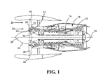
- a gas turbine engine constructed in accordance with the present disclosure is generally referred to by reference numeral 10.
- the gas turbine engine 10 includes a compressor section 12, a combustor 14 and a turbine section 16.
- the serial combination of the compressor section 12, the combustor 14 and the turbine section 16 is commonly referred to as a core engine 18.
- the engine 10 is circumscribed about a longitudinal central axis 20.
- the pressurized air then enters the combustor 14.
- the air mixes with jet fuel and is burned, generating hot combustion gases that flow downstream to the turbine section 16.
- the turbine section 16 extracts energy from the hot combustion gases to drive the compressor section 12 and a fan 24, which includes a plurality of airfoils 26 (two airfoils shown in FIG. 1 ).
- the airfoils 26 rotate so as to take in more ambient air. This process accelerates the ambient air 28 to provide the majority of the useful thrust produced by the engine 10.
- the fan 24 has a much greater diameter than the core engine 18. Because of this, the ambient air flow 28 through the fan 24 can be 5-10 times higher, or more, than the core air flow 30 through the core engine 18.
- the ratio of flow through the fan 24 relative to flow through the core engine 18 is known as the bypass ratio.
- the fan 24 includes a rotor disk 32 from which the airfoils 26 extend radially outwardly.
- the airfoils 26 are circumferentially spaced apart from one another around the rotor disk 32.
- Each of the airfoils 26 includes a pressure surface side 34 and an opposite-facing suction surface side 36.
- a conical spinner 38 extends from the upstream side of the rotor disk 32 and defines an aerodynamic flow path.
- the fan 24 also includes a plurality of discrete fan platforms 40 (only one shown in FIG. 1 ). Each discrete fan platform of the plurality of discrete fan platforms 40 is disposed between adjacent airfoils 26.
- each airfoil 26 may extend in a chordwise direction between a leading edge 42 and a trailing edge 44 and may extend in a spanwise direction between a tip 46 and a transition portion 48.
- the transition portion 48 is integrally joined to a dovetail root 50, which may be insertably retained into a corresponding dovetail slot 52 disposed on the rotor disk 32.
- a sheath 53 covers the leading edge 42 and may extend in a spanwise direction between the tip 46 and the transition portion 48.
- the sheath 53 includes a pressure side flange 54, which covers a minimum section of the pressure surface side 34.
- the sheath 53 also includes a suction side flange 56, which covers a minimum section of the suction surface side 36.
- the flanges 54, 56 cover an appropriate minimum section of the respective surface sides 34, 36 to ensure adequate joining of the sheath 53 to the airfoil 26 without adding undue weight to the airfoil 26. Because the sheath 53 is formed of a stronger material than the airfoil 26, the sheath 53 protects the leading edge 42 from impact damage from foreign objects such as from bird strikes.
- the airfoil 26 may be formed of aluminum or various aluminum alloys.
- the airfoil 26 may be coated with a protective coating, such as polyurethane or other protective coatings, which prevents erosion, but may have insulation qualities that inhibit grounding of the airfoil 26.
- the sheath 53 may be formed of a stronger, more conductive material than the airfoil 26 such as, but not limited to, titanium, titanium alloys, or other appropriate metals. Because the sheath 53 and airfoil 26 are formed of different materials, an electrical charge may build up in the sheath 53 creating a galvanic potential between the different materials during operation.
- each discrete fan platform 40 includes a first side 58, a second side 60, and an outer flow path surface 62 extending between the first and second sides 58, 60.
- the fan platform 40 also includes an inner surface 64 that extends between the first and second sides 58, 60 and oppositely faces the outer flow path surface 62.
- the outer flow path surface 62 and the inner surface 64 both extend axially between an upstream end 66 disposed adjacent to the spinner 38 and a downstream end 68 disposed adjacent to the compressor inlet 22.
- the outer flow path surface 62 of each discrete fan platform 40 is contoured so that, during engine 10 operation, it defines a continuous aerodynamic flow path with the spinner 38 allowing the air flow 30 to pass smoothly into the compressor inlet 22.
- the first side 58 may be contoured to complementarily match the contour of the pressure surface side 34 of its adjacent airfoil 26.
- the second side 60 may be contoured to complementarily match the contour of the suction surface side 36 of its adjacent airfoil 26.
- the fan platform 40 also includes a body portion 69 that extends radially inwardly from the inner surface 64.
- the body portion 69 may include a plurality of attachment members, such as, but not limited to, a plurality of clevises 70 (one clevis shown in FIG. 3 ) or a plurality of platform hooks 71 (one platform hook shown in FIG. 4 ), for attachment to the rotor disk 32.
- a pin 72 may be inserted through the plurality of clevises 70 and a corresponding plurality of lugs 73 (one shown in FIG.
- the pin 72 may be formed of any conductive material such as, but not limited to, titanium, titanium alloy, copper, steel, and nickel.
- the fan platform 40 may be formed of various materials, such as metal, composite, chopped and woven fiber, and non-coated plastic, to name a few non-limiting examples.
- a first edge seal 74 may be disposed on the first side 58 and a second edge seal 76 may be disposed on the second side 60.
- the first edge seal 74 includes a pressure side contact region 78, which may engage the pressure surface side 34 of an adjacent airfoil 26, and a pressure side flange contact region 80, which may engage the pressure side flange 54 of the sheath 53 of the adjacent airfoil 26.
- the second edge seal 76 includes a suction side contact region 82, which may engage the suction surface side 36 of an adjacent airfoil 26, and a suction side flange contact region 84, which may engage the suction side flange 56 of the adjacent sheath 53 of the adjacent airfoil 26.
- the pressure side flange contact region 80 also engages a first platform contact region 86, which is adjacent the upstream end 66.
- the suction side flange contact region 84 engages a second platform contact region 88, which is also adjacent the upstream end 66.
- the edge seals 74, 76 also protect against wear damage by preventing direct contact of the fan platform 40 with the adjacent airfoils 26 during engine 10 operation.
- the first and second edge seals 74, 76 may be formed of, but not limited to, rubber or braided composite.
- the first conductive path 90 for grounding may travel from the pressure side flange 54 of the sheath 53 via the pressure side flange contact region 80 of the first edge seal 74 via the first platform contact region 86 and then via the body portion 69 into the metallic rotor disk 32.
- the first conductive path 90 for grounding may be achieved by integrating a conductive material with the pressure side flange contact region 80, the first platform contact region 86, and the body portion 69.
- Each of the pressure side flange contact region 80, the first platform contact region 86, and the body portion 69 may be coated with the conductive material such that the conductive material on each component is in direct surface contact with the conductive material of the adjacent component so as to create the first conductive path 90 for grounding the sheath 53 to the rotor disk 32 during engine 10 operation.
- a conductive material may be formed integrally with each of the pressure side flange contact region 80, the first platform contact region 86, and the body portion 69 so that the conductive materials of each component engage in direct surface contact with the conductive material of the adjacent component so as to complete the first conductive path 90 for grounding the sheath 53 to the rotor disk 32 during engine 10 operation.
- the conductive material may be any suitable conductive material such as, but not limited to, titanium, titanium alloy, copper, steel or nickel.
- the coating may be done in any conventional manner such as, but not limited to, plating.
- a second conductive path 92 for grounding may travel from the suction side flange 56 of the sheath 53 via the suction side flange contact region 84 of the second edge seal 76 via the second platform contact region 88 and then via the body portion 69 into the metallic rotor disk 32.
- the second conductive path 92 for grounding the sheath 53 to the metallic rotor disk 32, during engine 10 operation may also be created by coating or forming integrally a conductive material with each of the suction side flange contact region 84, the second platform contact region 88, and the body portion 69 so that the conductive material of each component is in direct surface contact with the conductive material of the adjacent component.
- first and second conductive paths 90, 92 are described as being utilized in combination, it is also within the scope of the disclosure for either the first conductive path 90 or the second conductive path 92 to be utilized alone to dissipate the static electric charge built up in the sheath 53.
- the paths 90, 92 may include the conductive pin 72, which is in direct surface contact with the lug 73 of the rotor disk 32.
- the body portion 69 of the fan platform 40 may be fabricated from a conductive material, in which case, the body portion 69 would not need to be coated with a conductive material.
- FIG. 4 illustrates an embodiment that utilizes a plurality of platform hooks 71 (one shown) instead of a plurality of clevises 70 (see FIG. 3 ) to attach the body portion 69 of the fan platform 40 to the rotor disk 32.
- the first and second conductive paths 490, 492 are the same as the first and second paths 90, 92 described above, as the only difference is that the body portion 69 of the fan platform 40 is attached via platform hooks 71 instead of clevises 60.
- the plurality of platform hooks 71 may be attached to corresponding retention hooks 494 (one shown) disposed on the rotor disk 32.
- the rotation of the fan 24 forces the sheath 53 of each airfoil 26 to engage with the first and second edge seals 74, 76 of each fan platform 40.
- the first and second conductive paths 90, 92 are formed and allow the static electric charge built up in the sheath 53 to dissipate through the paths 90, 92 to the metallic rotor disk 32. With the sheath 53 grounded, the risk of galvanic corrosion between the sheath 53 and airfoil 26 is eliminated.
- FIG. 5 illustrates a flow chart 500 of a sample sequence of steps which may be performed for electrically grounding an airfoil of a gas turbine engine.
- Box 510 shows the step of providing a flow path surface and an inner surface both extending between a first side and a second side so that the inner surface radially opposes the flow path surface and a body portion extending radially inwardly from the inner surface.
- Another step, as illustrated in box 512 is forming at least a first conductive path for grounding that travels from the first side via the body portion.
- another step may be grounding the airfoil through the first conductive path.
- a first edge seal may be formed on the first side so that the at least first conductive path for grounding includes traveling from the first side to the body portion via the first edge seal.
- a second edge seal may be formed on the second side so that an at least second conductive path for grounding includes traveling from the second side via the second edge seal via the body portion.
- the at least first conductive path for grounding may be formed by coating each of the first side, the first edge seal, and the body portion in a conductive material.
- the at least second conductive path for grounding may be formed by coating each of the second side, the second edge seal, and the body portion in the conductive material.
- the at least first conductive path for grounding may also be formed by integrally forming a conductive material into each of the first side, the first edge seal, and the body portion.
- the at least second conductive path for grounding may also be formed by integrally forming a second conductive material into each of the second side, the second edge seal, and the body portion.
- the present disclosure sets forth a discrete fan platform for electrically grounding an airfoil of a gas turbine engine.
- the teachings of this disclosure can be employed to reduce part number count and assembly time for grounding the sheath of an airfoil, while at the same time not increasing the overall weight of the engine.
- the sheath of the airfoil may be grounded with less risk of disturbances to the grounding path over time and thus reducing maintenance costs.
- the present disclosure ensures that galvanic corrosion will not occur on bi-metallic or multi-material airfoils.
Landscapes
- Engineering & Computer Science (AREA)
- Mechanical Engineering (AREA)
- General Engineering & Computer Science (AREA)
- Chemical & Material Sciences (AREA)
- Materials Engineering (AREA)
- Structures Of Non-Positive Displacement Pumps (AREA)
Abstract
Description
- The subject matter of the present disclosure relates generally to gas turbine engines and, more particularly, relates to fan platforms.
- Gas turbine engines include a plurality of airfoils disposed circumferentially around the perimeter of a rotor disk. For optimum engine performance, it is ideal that the airfoils be light weight and stiff. As such, the material for airfoils has generally been changed from titanium to aluminum to reduce the weight of the airfoils. The aluminum airfoils do not share the same impact strength properties of titanium airfoils, however. In some instances, the aluminum airfoil is therefore covered with a polyurethane coating for protection. Additionally, the aluminum airfoil is also typically equipped with a protective sheath along the leading edge to improve impact strength and prevent airfoil damage from foreign object impact, such as impact with birds, hail or other debris. Often times the sheath is made from titanium or other high strength materials for protecting the airfoil from damage such as cracking, delamination, or deformation caused by impacting foreign objects.
- During engine operation, these bi-metallic, multi-material airfoils create a static electric charge between the different materials, which may create a galvanic potential causing galvanic corrosion to occur between the different materials. Traditionally, the blade and the rotor disk were made of the same material or of materials that did not create a galvanic potential. With the implementation of the bi-metallic airfoils, which cannot be directly grounded to the rotor disk, other techniques for grounding the airfoil have needed to be utilized. For example, a spinner may include an electrically conductive aft edge, which facilitates in grounding the airfoil. As another example, a grounding tab may be adhesively connected to each airfoil so that the grounding tab directly engages a component that is in contact with the rotor disk or directly engages the rotor disk itself so that an electrical connection is formed to ground the airfoil to the rotor disk. The adhesive needs to have an insulating property so that the grounding tab does not create galvanic corrosion between the grounding tab and the main body portion of the airfoil to which it is attached. While effective, the grounding tabs are connected to the airfoils by an insulating adhesive, which, over time, may deteriorate and cause the grounding tab to become dislodged. The dislodged grounding tabs could create gaps between itself and the airfoil, thereby permitting moisture to penetrate therebetween and effecting the grounding connection. In addition, the use of grounding tabs adds additional components and manufacturing steps to the assembly process. Similarly, while effective, the spinner with an electrically conductive aft edge for grounding the airfoil also requires additional components to ensure that the aft edge is electrically isolated from the main body portion of the airfoil.
- Accordingly, there is a need to provide a grounding path to prevent galvanic corrosion from occurring on bi-metallic airfoils that requires fewer components to thereby reduce assembly time and cost, while at the same time not increasing the overall weight of the engine.
- In accordance with an aspect of the disclosure, a fan platform for electrically grounding an airfoil of a gas turbine engine is provided. The fan platform may include a flow path surface extending between a first side and a second side. An inner surface may also extend between the first and second side so that the inner surface radially opposes the flow path surface. A body portion may extend radially inwardly from the inner surface. At least a first conductive path for grounding may travel along the first side via the body portion.
- In accordance with another aspect of the disclosure, a first edge seal may be disposed on the first side so that the at least first conductive path includes traveling from the first side to the body portion via the first edge seal.
- In accordance with yet another aspect of the disclosure, at least a second conductive path for grounding may travel via the second side via the body portion.
- In accordance with still yet another aspect of the disclosure, a second edge seal may be disposed on the second side so that the at least second conductive path may travel from the second side to the body portion via the second edge seal.
- In further accordance with another aspect of the disclosure, the body portion may include a plurality of clevises.
- In further accordance with yet another aspect of the disclosure, the body portion may include a plurality of hooks.
- In further accordance with still yet another aspect of the disclosure, the at least first conductive path may be formed by coating the first edge seal, the first side, and the body portion in a conductive material. The at least second conductive path may be formed by coating the second edge seal, the second side, and the body portion in the conductive material.
- In further accordance with an even further aspect of the disclosure, the at least first conductive path may be formed by integrally forming a first conductive material into each of the first edge seal, the first side, and the body portion. The at least second conductive path may be formed by integrally forming a second conductive material into each of the second edge seal, the second side, and the body portion.
- In accordance with another aspect of the disclosure, a gas turbine engine is provided. The gas turbine may include a rotor disk with a plurality of airfoils extending radially outwardly therefrom so that each airfoil of the plurality of airfoils may be circumferentially spaced apart from one another. A sheath may cover a leading edge of each airfoil. A plurality of discrete fan platforms may be disposed between adjacent airfoils. Each discrete fan platform may include a flow path surface and an inner surface both extending between a first and second side so that the inner surface radially opposes the flow path surface. A body portion may extend radially inwardly from the inner surface and may be disposed on the rotor disk. At least a first conductive path for grounding the sheath may operatively travel from the sheath along the first side via the body portion to the rotor disk.
- In accordance with still another aspect of the disclosure, a first edge seal may be disposed on the first side so that the at least first conductive path includes operatively traveling from the sheath to the first side via the first edge seal.
- In accordance with still yet another aspect of the disclosure, at least a second conductive path for grounding a sheath of an adjacent airfoil may operatively travel from the sheath of the adjacent airfoil via the second side via the body portion to the rotor disk.
- In accordance with an even further aspect of the disclosure, a second edge seal may be disposed on the second side so that the at least second conductive path for grounding the sheath of the adjacent airfoil may operatively travel from the sheath of the adjacent airfoil to the second side via the second edge seal.
- In accordance with still an even further aspect of the disclosure, the body portion may include a plurality of clevises attached to corresponding lugs disposed on the rotor disk.
- In further accordance with yet another aspect of the disclosure, the body portion may include a plurality of platform hooks retained to corresponding retention hooks disposed on the rotor disk.
- In accordance with another aspect of the disclosure, a method of electrically grounding an airfoil of a gas turbine engine is provided. The method entails providing a flow path surface and an inner surface both extending between a first side and a second side so that the inner surface radially opposes the flow path surface and a body portion extending radially inwardly from the inner surface. Another step may be forming at least a first conductive path for grounding that travels from the first side via the body portion. Yet another step may include grounding the airfoil through the at least first conductive path.
- In accordance with yet another aspect of the disclosure, the method may include forming a first edge seal on the first side so that the at least first conductive path for grounding includes traveling from the first side to the body portion via the first edge seal and forming a second edge seal on the second side so that an least second conductive path for grounding includes traveling from the second side via the second edge seal via the body portion.
- In accordance with still yet another aspect of the disclosure, the method may include forming the at least first conductive path for grounding by coating each of the first side, the first edge seal, and the body portion in a conductive material, and forming the at least second conductive path for grounding by coating each of the second side, the second edge seal, and the body portion in the conductive material.
- In accordance with still an even further aspect of the disclosure, the method may include forming the at least first conductive path for grounding by integrally forming a conductive material into each of the first side, the first edge seal, and the body portion, and forming the at least second conductive path for grounding by integrally forming a second conductive material into each of the second side, the second edge seal, and the body portion.
- Other aspects and features of the disclosed systems and methods will be appreciated from reading the attached detailed description in conjunction with the included drawing figures. Moreover, selected aspects and features of one example embodiment may be combined with various selected aspects and features of other example embodiments.
- For further understanding of the disclosed concepts and embodiments, reference may be made to the following detailed description, read in connection with the drawings, wherein like elements are numbered alike, and in which:
-
FIG. 1 is a side view of a gas turbine engine with portions sectioned and broken away to show details of the present disclosure; -
FIG. 2 is a perspective view looking radially inwardly to show details of the present disclosure; -
FIG. 3 is a front view taken along line 3-3 ofFIG. 2 with portions sectioned and broken away to show details of the present disclosure; -
FIG. 4 is a front view similar toFIG. 3 , but depicting an alternative embodiment constructed in accordance with the teachings of the present disclosure; and -
FIG. 5 is a flowchart illustrating a sample sequence of steps which may be practiced in accordance with the teachings of this disclosure. - It is to be noted that the appended drawings illustrate only typical embodiments and are therefore not to be considered limiting with respect to the scope of the disclosure or claims. Rather, the concepts of the present disclosure may apply within other equally effective embodiments. Moreover, the drawings are not necessarily to scale, emphasis generally being placed upon illustrating the principles of certain embodiments.
- Throughout this specification the terms "downstream" and "upstream" are used with reference to the general direction of gas flow through the engine and the terms "axial", "radial" and "circumferential" are generally used with respect to the longitudinal central engine axis.
- Referring now to
FIG. 1 , a gas turbine engine constructed in accordance with the present disclosure is generally referred to by reference numeral 10. The gas turbine engine 10 includes acompressor section 12, acombustor 14 and aturbine section 16. The serial combination of thecompressor section 12, thecombustor 14 and theturbine section 16 is commonly referred to as acore engine 18. The engine 10 is circumscribed about a longitudinalcentral axis 20. - Air enters the
compressor section 12 at thecompressor inlet 22 and is pressurized. The pressurized air then enters thecombustor 14. In thecombustor 14, the air mixes with jet fuel and is burned, generating hot combustion gases that flow downstream to theturbine section 16. Theturbine section 16 extracts energy from the hot combustion gases to drive thecompressor section 12 and afan 24, which includes a plurality of airfoils 26 (two airfoils shown inFIG. 1 ). As theturbine section 16 drives thefan 24, theairfoils 26 rotate so as to take in more ambient air. This process accelerates theambient air 28 to provide the majority of the useful thrust produced by the engine 10. Generally, in some modem gas turbine engines, thefan 24 has a much greater diameter than thecore engine 18. Because of this, theambient air flow 28 through thefan 24 can be 5-10 times higher, or more, than thecore air flow 30 through thecore engine 18. The ratio of flow through thefan 24 relative to flow through thecore engine 18 is known as the bypass ratio. - The
fan 24 includes arotor disk 32 from which theairfoils 26 extend radially outwardly. Theairfoils 26 are circumferentially spaced apart from one another around therotor disk 32. Each of theairfoils 26 includes apressure surface side 34 and an opposite-facingsuction surface side 36. Aconical spinner 38 extends from the upstream side of therotor disk 32 and defines an aerodynamic flow path. Thefan 24 also includes a plurality of discrete fan platforms 40 (only one shown inFIG. 1 ). Each discrete fan platform of the plurality ofdiscrete fan platforms 40 is disposed betweenadjacent airfoils 26. - A more detailed description of the
airfoils 26 is discussed below with particular reference toFIGS. 2 and3 . Thepressure surface side 34 and thesuction surface side 36 of eachairfoil 26 may extend in a chordwise direction between aleading edge 42 and a trailingedge 44 and may extend in a spanwise direction between atip 46 and atransition portion 48. Thetransition portion 48 is integrally joined to adovetail root 50, which may be insertably retained into acorresponding dovetail slot 52 disposed on therotor disk 32. - A
sheath 53 covers the leadingedge 42 and may extend in a spanwise direction between thetip 46 and thetransition portion 48. Thesheath 53 includes apressure side flange 54, which covers a minimum section of thepressure surface side 34. Similarly, thesheath 53 also includes asuction side flange 56, which covers a minimum section of thesuction surface side 36. Theflanges sheath 53 to theairfoil 26 without adding undue weight to theairfoil 26. Because thesheath 53 is formed of a stronger material than theairfoil 26, thesheath 53 protects the leadingedge 42 from impact damage from foreign objects such as from bird strikes. As a non-limiting example, theairfoil 26 may be formed of aluminum or various aluminum alloys. In addition, theairfoil 26 may be coated with a protective coating, such as polyurethane or other protective coatings, which prevents erosion, but may have insulation qualities that inhibit grounding of theairfoil 26. Thesheath 53, on the other hand, may be formed of a stronger, more conductive material than theairfoil 26 such as, but not limited to, titanium, titanium alloys, or other appropriate metals. Because thesheath 53 andairfoil 26 are formed of different materials, an electrical charge may build up in thesheath 53 creating a galvanic potential between the different materials during operation. - As shown in
FIGS. 2 and3 , eachdiscrete fan platform 40 includes afirst side 58, asecond side 60, and an outer flow path surface 62 extending between the first andsecond sides fan platform 40 also includes aninner surface 64 that extends between the first andsecond sides inner surface 64 both extend axially between anupstream end 66 disposed adjacent to thespinner 38 and adownstream end 68 disposed adjacent to thecompressor inlet 22. The outer flow path surface 62 of eachdiscrete fan platform 40 is contoured so that, during engine 10 operation, it defines a continuous aerodynamic flow path with thespinner 38 allowing theair flow 30 to pass smoothly into thecompressor inlet 22. Thefirst side 58 may be contoured to complementarily match the contour of thepressure surface side 34 of itsadjacent airfoil 26. Similarly, thesecond side 60 may be contoured to complementarily match the contour of thesuction surface side 36 of itsadjacent airfoil 26. - The
fan platform 40 also includes abody portion 69 that extends radially inwardly from theinner surface 64. Thebody portion 69 may include a plurality of attachment members, such as, but not limited to, a plurality of clevises 70 (one clevis shown inFIG. 3 ) or a plurality of platform hooks 71 (one platform hook shown inFIG. 4 ), for attachment to therotor disk 32. In particular, for abody portion 69 that includes a plurality ofclevises 70, apin 72 may be inserted through the plurality ofclevises 70 and a corresponding plurality of lugs 73 (one shown inFIG. 3 ) disposed on therotor disk 32 to secure thefan platform 40 to therotor disk 32. Thepin 72 may be formed of any conductive material such as, but not limited to, titanium, titanium alloy, copper, steel, and nickel. Thefan platform 40 may be formed of various materials, such as metal, composite, chopped and woven fiber, and non-coated plastic, to name a few non-limiting examples. - A first edge seal 74 may be disposed on the
first side 58 and a second edge seal 76 may be disposed on thesecond side 60. The first edge seal 74 includes a pressure side contact region 78, which may engage thepressure surface side 34 of anadjacent airfoil 26, and a pressure sideflange contact region 80, which may engage thepressure side flange 54 of thesheath 53 of theadjacent airfoil 26. In similar fashion, the second edge seal 76 includes a suction side contact region 82, which may engage thesuction surface side 36 of anadjacent airfoil 26, and a suction sideflange contact region 84, which may engage thesuction side flange 56 of theadjacent sheath 53 of theadjacent airfoil 26. The pressure sideflange contact region 80 also engages a firstplatform contact region 86, which is adjacent theupstream end 66. Similarly, the suction sideflange contact region 84 engages a secondplatform contact region 88, which is also adjacent theupstream end 66. In addition to preventing air from flowing through gaps between thediscrete fan platform 40 andadjacent airfoils 26, the edge seals 74, 76 also protect against wear damage by preventing direct contact of thefan platform 40 with theadjacent airfoils 26 during engine 10 operation. The first and second edge seals 74, 76 may be formed of, but not limited to, rubber or braided composite. - In an embodiment where the
sheath 53 is formed of a material that is more conductive than the material of theairfoil 26, the static electric charge that may build up in thesheath 53, during engine 10 operation, needs to dissipate through a first conductive path 90 for grounding to prevent a galvanic potential from forming and causing galvanic corrosion between the different materials. During engine 10 operation, the first conductive path 90 for grounding may travel from thepressure side flange 54 of thesheath 53 via the pressure sideflange contact region 80 of the first edge seal 74 via the firstplatform contact region 86 and then via thebody portion 69 into themetallic rotor disk 32. The first conductive path 90 for grounding may be achieved by integrating a conductive material with the pressure sideflange contact region 80, the firstplatform contact region 86, and thebody portion 69. Each of the pressure sideflange contact region 80, the firstplatform contact region 86, and thebody portion 69 may be coated with the conductive material such that the conductive material on each component is in direct surface contact with the conductive material of the adjacent component so as to create the first conductive path 90 for grounding thesheath 53 to therotor disk 32 during engine 10 operation. Instead of coating, a conductive material may be formed integrally with each of the pressure sideflange contact region 80, the firstplatform contact region 86, and thebody portion 69 so that the conductive materials of each component engage in direct surface contact with the conductive material of the adjacent component so as to complete the first conductive path 90 for grounding thesheath 53 to therotor disk 32 during engine 10 operation. The conductive material may be any suitable conductive material such as, but not limited to, titanium, titanium alloy, copper, steel or nickel. The coating may be done in any conventional manner such as, but not limited to, plating. - In a similar fashion, a second
conductive path 92 for grounding may travel from thesuction side flange 56 of thesheath 53 via the suction sideflange contact region 84 of the second edge seal 76 via the secondplatform contact region 88 and then via thebody portion 69 into themetallic rotor disk 32. Similar to the first conductive path 90, the secondconductive path 92 for grounding thesheath 53 to themetallic rotor disk 32, during engine 10 operation, may also be created by coating or forming integrally a conductive material with each of the suction sideflange contact region 84, the secondplatform contact region 88, and thebody portion 69 so that the conductive material of each component is in direct surface contact with the conductive material of the adjacent component. - Although the first and second
conductive paths 90, 92 are described as being utilized in combination, it is also within the scope of the disclosure for either the first conductive path 90 or the secondconductive path 92 to be utilized alone to dissipate the static electric charge built up in thesheath 53. Furthermore, in any combination of utilizing the first and secondconductive paths 90, 92 in which thepaths 90, 92 are partially formed integrally with thebody portion 69 of thefan platform 40, thepaths 90, 92 may include theconductive pin 72, which is in direct surface contact with thelug 73 of therotor disk 32. It should also be noted that thebody portion 69 of thefan platform 40 may be fabricated from a conductive material, in which case, thebody portion 69 would not need to be coated with a conductive material. -
FIG. 4 illustrates an embodiment that utilizes a plurality of platform hooks 71 (one shown) instead of a plurality of clevises 70 (seeFIG. 3 ) to attach thebody portion 69 of thefan platform 40 to therotor disk 32. The first and secondconductive paths second paths 90, 92 described above, as the only difference is that thebody portion 69 of thefan platform 40 is attached via platform hooks 71 instead ofclevises 60. In particular, the plurality of platform hooks 71 may be attached to corresponding retention hooks 494 (one shown) disposed on therotor disk 32. - During engine 10 operation, the rotation of the
fan 24 forces thesheath 53 of eachairfoil 26 to engage with the first and second edge seals 74, 76 of eachfan platform 40. In this operating configuration, the first and secondconductive paths 90, 92 are formed and allow the static electric charge built up in thesheath 53 to dissipate through thepaths 90, 92 to themetallic rotor disk 32. With thesheath 53 grounded, the risk of galvanic corrosion between thesheath 53 andairfoil 26 is eliminated. -
FIG. 5 illustrates aflow chart 500 of a sample sequence of steps which may be performed for electrically grounding an airfoil of a gas turbine engine.Box 510 shows the step of providing a flow path surface and an inner surface both extending between a first side and a second side so that the inner surface radially opposes the flow path surface and a body portion extending radially inwardly from the inner surface. Another step, as illustrated inbox 512, is forming at least a first conductive path for grounding that travels from the first side via the body portion. As shown inbox 514, another step may be grounding the airfoil through the first conductive path. A first edge seal may be formed on the first side so that the at least first conductive path for grounding includes traveling from the first side to the body portion via the first edge seal. A second edge seal may be formed on the second side so that an at least second conductive path for grounding includes traveling from the second side via the second edge seal via the body portion. The at least first conductive path for grounding may be formed by coating each of the first side, the first edge seal, and the body portion in a conductive material. The at least second conductive path for grounding may be formed by coating each of the second side, the second edge seal, and the body portion in the conductive material. The at least first conductive path for grounding may also be formed by integrally forming a conductive material into each of the first side, the first edge seal, and the body portion. Similarly, the at least second conductive path for grounding may also be formed by integrally forming a second conductive material into each of the second side, the second edge seal, and the body portion. - While the present disclosure has shown and described details of exemplary embodiments, it will be understood by one skilled in the art that various changes in detail may be effected therein without departing from the spirit and scope of the disclosure as defined by claims supported by the written description and drawings. Further, where these exemplary embodiments (and other related derivations) are described with reference to a certain number of elements it will be understood that other exemplary embodiments may be practiced utilizing either less than or more than the certain number of elements.
- Based on the foregoing, it can be seen that the present disclosure sets forth a discrete fan platform for electrically grounding an airfoil of a gas turbine engine. The teachings of this disclosure can be employed to reduce part number count and assembly time for grounding the sheath of an airfoil, while at the same time not increasing the overall weight of the engine. Moreover, through the novel teachings set forth above, the sheath of the airfoil may be grounded with less risk of disturbances to the grounding path over time and thus reducing maintenance costs. Furthermore, the present disclosure ensures that galvanic corrosion will not occur on bi-metallic or multi-material airfoils.
Claims (15)
- A fan platform (40) for electrically grounding an airfoil (46) of a gas turbine engine, the fan platform (40) comprising:a flow path surface (62) extending between a first and second side (58, 60);an inner surface (64) extending between the first and second sides (58, 60), the inner surface (64) radially opposing the flow path surface (62);a body portion (69) extending radially inwardly from the inner surface (64); andat least a first conductive path for grounding, the at least first conductive path (90; 490) traveling along the first side (58) via the body portion (69).
- The fan platform of claim 1, further including a first edge seal (74) disposed on the first side (58), the at least first conductive path (90; 490) includes traveling from the first side (58) to the body portion (69) via the first edge seal (74).
- The fan platform of claim 2, further including at least a second conductive path (92; 492) for grounding, the at least second conductive path (92; 492) traveling via the second side (60) via the body portion (69).
- The fan platform of claim 3, further including a second edge seal (76) disposed on the second side (60), the at least second conductive path (92; 492) traveling from the second side (60) to the body portion (69) via the second edge seal (76).
- The fan platform of any preceding claim, wherein the body portion (69) includes a plurality of clevises (70).
- The fan platform of any of claims 1 to 4, wherein the body portion includes a plurality of hooks (71).
- The fan platform of claim 4, 5 or 6, wherein the at least first conductive path (90; 490) is formed by coating the first edge seal (74), the first side (58), and the body portion (69) in a conductive material, and the at least second conductive path (92; 492) is formed by coating the second edge seal (76), the second side (60) and the body portion (69) in the conductive material.
- The fan platform of claim 4, 5 or 6 wherein the at least first conductive path (90; 490) is formed by integrally forming a first conductive material into each of the first edge seal (74), the first side (58), and the body portion (69), and the at least second conductive path (92; 492) is formed by integrally forming a second conductive material into each of the second edge seal (76), the second side (60) and the body portion (69).
- A gas turbine engine, the engine comprising:a rotor disk (32);a plurality of airfoils (46) extending radially outwardly from the rotor disk (32), each airfoil (46) of the plurality of airfoils being circumferentially spaced apart from one another;a sheath (53) covering a leading edge (42) of each airfoil (46); anda plurality of discrete fan platforms (40) as set forth in any preceding claim being disposed between adjacent airfoils (46), the body portion being disposed on the rotor disk, and the at least a first conductive path (90; 490) for grounding the sheath (53), and operatively traveling from the sheath (53) along the first side (58) via the body portion (69) to the rotor disk (32).
- The gas turbine engine of claim 9, further including at least a second conductive path (92; 492) for grounding a sheath (53) of an adjacent airfoil (46), the at least second conductive path (92; 492) operatively traveling from the sheath (53) of the adjacent airfoil (46) via the second side (60) via the body portion (69) to the rotor disk (32).
- The gas turbine engine of claim 10, further including a second edge seal (76) disposed on the second side (60), the at least second conductive path (92; 492) for grounding the sheath (53) of the adjacent airfoil (46) includes operatively traveling from the sheath (53) of the adjacent airfoil (46) to the second side (60) via the second edge seal (76).
- The gas turbine engine of claim 9, 10 or 11, wherein the body portion (69) includes a plurality of clevises (70) attached to corresponding lugs (73) disposed on the rotor disk (32), or wherein the body portion (69) includes a plurality of platform hooks (71) retained to corresponding retention hooks (494) disposed on the rotor disk (32).
- A method of electrically grounding an airfoil (46) of a gas turbine engine, the method comprising:providing a flow path surface (62) and an inner surface (64) both extending between a first side (58) and a second side (60) so that the inner surface (64) radially opposes the flow path surface (62) and a body portion (69) extending radially inwardly from the inner surface (64);forming at least a first conductive path (90; 490) for grounding that travels from the first side (58) via the body portion (69); andgrounding the airfoil (46) through the at least first conductive path (90; 490).
- The method of claim 13, further including forming a first edge seal (74) on the first side (58) so that the at least first conductive path (90; 490) for grounding includes traveling from the first side (58) to the body portion (69) via the first edge seal (74), and a second edge seal (76) on the second side (60) so that an at least second conductive path (92; 492) for grounding includes traveling from the second side (60) via the second edge seal (76) via the body portion (69).
- The method of claim 14, further including forming the at least first conductive path (90; 490) for grounding by coating each of the first side (58), the first edge seal (74), and the body portion (69) in a conductive material, and forming the at least second conductive path (92; 492) for grounding by coating each of the second side (60), the second edge seal (76), and the body portion (69) in the conductive material, or forming the at least first conductive path (90; 490) for grounding by integrally forming a conductive material into each of the first side (58), the first edge seal (74), and the body portion (69), and forming the at least second conductive path (92; 492) for grounding by integrally forming a second conductive material into each of the second side (60), the second edge seal (76), and the body portion (69).
Applications Claiming Priority (1)
| Application Number | Priority Date | Filing Date | Title |
|---|---|---|---|
| US201461978597P | 2014-04-11 | 2014-04-11 |
Publications (2)
| Publication Number | Publication Date |
|---|---|
| EP2930306A1 true EP2930306A1 (en) | 2015-10-14 |
| EP2930306B1 EP2930306B1 (en) | 2020-02-26 |
Family
ID=53268595
Family Applications (1)
| Application Number | Title | Priority Date | Filing Date |
|---|---|---|---|
| EP15163435.9A Active EP2930306B1 (en) | 2014-04-11 | 2015-04-13 | Gas turbine engine fan with discrete platforms for electrically grounding sheaths of fan airfoils |
Country Status (2)
| Country | Link |
|---|---|
| US (1) | US11118463B2 (en) |
| EP (1) | EP2930306B1 (en) |
Cited By (2)
| Publication number | Priority date | Publication date | Assignee | Title |
|---|---|---|---|---|
| EP3318718A1 (en) * | 2016-11-02 | 2018-05-09 | United Technologies Corporation | Fan for a gas turbine engine an corresponding method of securing fan blades to a rotor of a fan of a gas turbine engine |
| EP3382145A1 (en) * | 2017-03-27 | 2018-10-03 | United Technologies Corporation | Apparatus and method for non-destructive detection of fan blade electrical isolation |
Families Citing this family (1)
| Publication number | Priority date | Publication date | Assignee | Title |
|---|---|---|---|---|
| US11359500B2 (en) * | 2018-10-18 | 2022-06-14 | Raytheon Technologies Corporation | Rotor assembly with structural platforms for gas turbine engines |
Citations (6)
| Publication number | Priority date | Publication date | Assignee | Title |
|---|---|---|---|---|
| US6634863B1 (en) * | 2000-11-27 | 2003-10-21 | General Electric Company | Circular arc multi-bore fan disk assembly |
| US20050276691A1 (en) * | 2003-07-31 | 2005-12-15 | Snecma Moteurs | Inter-vane platform with lateral deflection for a vane support of a turbine engine |
| US20100209251A1 (en) * | 2009-02-18 | 2010-08-19 | Menheere David H | Fan blade platform |
| US20110243709A1 (en) * | 2010-04-05 | 2011-10-06 | El-Aini Yehia M | Non-integral platform and damper for an airfoil |
| US20120167390A1 (en) * | 2010-12-30 | 2012-07-05 | Edward Claude Rice | Airfoil for gas turbine engine |
| WO2014137448A1 (en) * | 2013-03-08 | 2014-09-12 | United Technologies Corporation | Fan blades with protective sheaths and galvanic shields |
Family Cites Families (7)
| Publication number | Priority date | Publication date | Assignee | Title |
|---|---|---|---|---|
| US3694104A (en) * | 1970-10-07 | 1972-09-26 | Garrett Corp | Turbomachinery blade |
| GB9208409D0 (en) * | 1992-04-16 | 1992-06-03 | Rolls Royce Plc | Rotors for gas turbine engines |
| FR2706528B1 (en) * | 1993-06-10 | 1995-09-01 | Snecma | Separate inter-blade platform of turbine engine rotor blade disc. |
| US6447250B1 (en) * | 2000-11-27 | 2002-09-10 | General Electric Company | Non-integral fan platform |
| US20060137587A1 (en) * | 2004-11-08 | 2006-06-29 | Integral Technologies, Inc. | Low cost components for use in motorcycle, marine, and racing applications manufactured from conductive loaded resin-based materials |
| EP2447476A3 (en) * | 2010-11-01 | 2017-11-15 | Rolls-Royce plc | Annulus filler for a rotor disk of a gas turbine |
| US9376924B2 (en) * | 2011-12-14 | 2016-06-28 | United Technologies Corporation | Electrical grounding for fan blades |
-
2015
- 2015-01-15 US US14/597,902 patent/US11118463B2/en active Active
- 2015-04-13 EP EP15163435.9A patent/EP2930306B1/en active Active
Patent Citations (6)
| Publication number | Priority date | Publication date | Assignee | Title |
|---|---|---|---|---|
| US6634863B1 (en) * | 2000-11-27 | 2003-10-21 | General Electric Company | Circular arc multi-bore fan disk assembly |
| US20050276691A1 (en) * | 2003-07-31 | 2005-12-15 | Snecma Moteurs | Inter-vane platform with lateral deflection for a vane support of a turbine engine |
| US20100209251A1 (en) * | 2009-02-18 | 2010-08-19 | Menheere David H | Fan blade platform |
| US20110243709A1 (en) * | 2010-04-05 | 2011-10-06 | El-Aini Yehia M | Non-integral platform and damper for an airfoil |
| US20120167390A1 (en) * | 2010-12-30 | 2012-07-05 | Edward Claude Rice | Airfoil for gas turbine engine |
| WO2014137448A1 (en) * | 2013-03-08 | 2014-09-12 | United Technologies Corporation | Fan blades with protective sheaths and galvanic shields |
Cited By (4)
| Publication number | Priority date | Publication date | Assignee | Title |
|---|---|---|---|---|
| EP3318718A1 (en) * | 2016-11-02 | 2018-05-09 | United Technologies Corporation | Fan for a gas turbine engine an corresponding method of securing fan blades to a rotor of a fan of a gas turbine engine |
| US10563666B2 (en) | 2016-11-02 | 2020-02-18 | United Technologies Corporation | Fan blade with cover and method for cover retention |
| EP3382145A1 (en) * | 2017-03-27 | 2018-10-03 | United Technologies Corporation | Apparatus and method for non-destructive detection of fan blade electrical isolation |
| US10345799B2 (en) | 2017-03-27 | 2019-07-09 | United Technologies Corporation | Apparatus and method for non-destructive detection of fan blade electrical isolation |
Also Published As
| Publication number | Publication date |
|---|---|
| US20150292338A1 (en) | 2015-10-15 |
| US11118463B2 (en) | 2021-09-14 |
| EP2930306B1 (en) | 2020-02-26 |
Similar Documents
| Publication | Publication Date | Title |
|---|---|---|
| US8376712B2 (en) | Fan airfoil sheath | |
| US8721294B2 (en) | Airfoil with galvanically isolated metal coating | |
| US20170167510A1 (en) | Durable Riblets for Engine Environment | |
| US9995152B2 (en) | Hollow fan blade with extended wing sheath | |
| EP2971526B1 (en) | Locally extended leading edge sheath for fan airfoil | |
| US20160003060A1 (en) | Hybrid fan blades for jet engines | |
| US10883374B2 (en) | Blade comprising a folded leading edge shield and method of manufacturing the blade | |
| CN1869408B (en) | Coated forward stub shaft dovetail slot | |
| EP3040517B1 (en) | Radial lock for fan blade sheath | |
| EP3049635B1 (en) | Aluminum airfoil with titanium coating | |
| CN108474258B (en) | main edge guard | |
| CN111197596A (en) | Composite fan blades with abrasive tips | |
| US11118463B2 (en) | Electrically grounding fan platforms | |
| US20220074307A1 (en) | Gas turbine engine rotor blade having a root section with composite and metallic portions | |
| EP3049632B1 (en) | Fan blade assembly | |
| US10385703B2 (en) | Fan blades with protective sheaths and galvanic shields | |
| US20140219808A1 (en) | Sheath with extended wings | |
| WO2015047754A1 (en) | Fan blade assembly | |
| EP3049630B1 (en) | Fan blade assembly | |
| US20160305439A1 (en) | Fan platform edge seal | |
| EP3058180B1 (en) | Fan rotor with integrated platform attachment | |
| EP2905456B1 (en) | Fan assembly for a gas turbine |
Legal Events
| Date | Code | Title | Description |
|---|---|---|---|
| PUAI | Public reference made under article 153(3) epc to a published international application that has entered the european phase |
Free format text: ORIGINAL CODE: 0009012 |
|
| AK | Designated contracting states |
Kind code of ref document: A1 Designated state(s): AL AT BE BG CH CY CZ DE DK EE ES FI FR GB GR HR HU IE IS IT LI LT LU LV MC MK MT NL NO PL PT RO RS SE SI SK SM TR |
|
| AX | Request for extension of the european patent |
Extension state: BA ME |
|
| 17P | Request for examination filed |
Effective date: 20160414 |
|
| RBV | Designated contracting states (corrected) |
Designated state(s): AL AT BE BG CH CY CZ DE DK EE ES FI FR GB GR HR HU IE IS IT LI LT LU LV MC MK MT NL NO PL PT RO RS SE SI SK SM TR |
|
| RAP1 | Party data changed (applicant data changed or rights of an application transferred) |
Owner name: UNITED TECHNOLOGIES CORPORATION |
|
| STAA | Information on the status of an ep patent application or granted ep patent |
Free format text: STATUS: EXAMINATION IS IN PROGRESS |
|
| 17Q | First examination report despatched |
Effective date: 20180627 |
|
| GRAP | Despatch of communication of intention to grant a patent |
Free format text: ORIGINAL CODE: EPIDOSNIGR1 |
|
| STAA | Information on the status of an ep patent application or granted ep patent |
Free format text: STATUS: GRANT OF PATENT IS INTENDED |
|
| RIC1 | Information provided on ipc code assigned before grant |
Ipc: F01D 5/28 20060101AFI20181115BHEP Ipc: F01D 11/00 20060101ALI20181115BHEP Ipc: F01K 3/06 20060101ALN20181115BHEP |
|
| INTG | Intention to grant announced |
Effective date: 20181219 |
|
| GRAJ | Information related to disapproval of communication of intention to grant by the applicant or resumption of examination proceedings by the epo deleted |
Free format text: ORIGINAL CODE: EPIDOSDIGR1 |
|
| STAA | Information on the status of an ep patent application or granted ep patent |
Free format text: STATUS: EXAMINATION IS IN PROGRESS |
|
| GRAP | Despatch of communication of intention to grant a patent |
Free format text: ORIGINAL CODE: EPIDOSNIGR1 |
|
| STAA | Information on the status of an ep patent application or granted ep patent |
Free format text: STATUS: GRANT OF PATENT IS INTENDED |
|
| INTC | Intention to grant announced (deleted) | ||
| RIC1 | Information provided on ipc code assigned before grant |
Ipc: F01K 3/06 20060101ALN20190820BHEP Ipc: F01D 11/00 20060101ALI20190820BHEP Ipc: F01D 5/28 20060101AFI20190820BHEP |
|
| INTG | Intention to grant announced |
Effective date: 20190911 |
|
| GRAS | Grant fee paid |
Free format text: ORIGINAL CODE: EPIDOSNIGR3 |
|
| GRAA | (expected) grant |
Free format text: ORIGINAL CODE: 0009210 |
|
| STAA | Information on the status of an ep patent application or granted ep patent |
Free format text: STATUS: THE PATENT HAS BEEN GRANTED |
|
| AK | Designated contracting states |
Kind code of ref document: B1 Designated state(s): AL AT BE BG CH CY CZ DE DK EE ES FI FR GB GR HR HU IE IS IT LI LT LU LV MC MK MT NL NO PL PT RO RS SE SI SK SM TR |
|
| REG | Reference to a national code |
Ref country code: GB Ref legal event code: FG4D |
|
| REG | Reference to a national code |
Ref country code: CH Ref legal event code: EP |
|
| REG | Reference to a national code |
Ref country code: DE Ref legal event code: R096 Ref document number: 602015047598 Country of ref document: DE |
|
| REG | Reference to a national code |
Ref country code: AT Ref legal event code: REF Ref document number: 1237862 Country of ref document: AT Kind code of ref document: T Effective date: 20200315 |
|
| REG | Reference to a national code |
Ref country code: IE Ref legal event code: FG4D |
|
| PG25 | Lapsed in a contracting state [announced via postgrant information from national office to epo] |
Ref country code: RS Free format text: LAPSE BECAUSE OF FAILURE TO SUBMIT A TRANSLATION OF THE DESCRIPTION OR TO PAY THE FEE WITHIN THE PRESCRIBED TIME-LIMIT Effective date: 20200226 Ref country code: FI Free format text: LAPSE BECAUSE OF FAILURE TO SUBMIT A TRANSLATION OF THE DESCRIPTION OR TO PAY THE FEE WITHIN THE PRESCRIBED TIME-LIMIT Effective date: 20200226 Ref country code: NO Free format text: LAPSE BECAUSE OF FAILURE TO SUBMIT A TRANSLATION OF THE DESCRIPTION OR TO PAY THE FEE WITHIN THE PRESCRIBED TIME-LIMIT Effective date: 20200526 |
|
| REG | Reference to a national code |
Ref country code: NL Ref legal event code: MP Effective date: 20200226 |
|
| REG | Reference to a national code |
Ref country code: LT Ref legal event code: MG4D |
|
| PG25 | Lapsed in a contracting state [announced via postgrant information from national office to epo] |
Ref country code: SE Free format text: LAPSE BECAUSE OF FAILURE TO SUBMIT A TRANSLATION OF THE DESCRIPTION OR TO PAY THE FEE WITHIN THE PRESCRIBED TIME-LIMIT Effective date: 20200226 Ref country code: LV Free format text: LAPSE BECAUSE OF FAILURE TO SUBMIT A TRANSLATION OF THE DESCRIPTION OR TO PAY THE FEE WITHIN THE PRESCRIBED TIME-LIMIT Effective date: 20200226 Ref country code: IS Free format text: LAPSE BECAUSE OF FAILURE TO SUBMIT A TRANSLATION OF THE DESCRIPTION OR TO PAY THE FEE WITHIN THE PRESCRIBED TIME-LIMIT Effective date: 20200626 Ref country code: BG Free format text: LAPSE BECAUSE OF FAILURE TO SUBMIT A TRANSLATION OF THE DESCRIPTION OR TO PAY THE FEE WITHIN THE PRESCRIBED TIME-LIMIT Effective date: 20200526 Ref country code: GR Free format text: LAPSE BECAUSE OF FAILURE TO SUBMIT A TRANSLATION OF THE DESCRIPTION OR TO PAY THE FEE WITHIN THE PRESCRIBED TIME-LIMIT Effective date: 20200527 Ref country code: HR Free format text: LAPSE BECAUSE OF FAILURE TO SUBMIT A TRANSLATION OF THE DESCRIPTION OR TO PAY THE FEE WITHIN THE PRESCRIBED TIME-LIMIT Effective date: 20200226 |
|
| PG25 | Lapsed in a contracting state [announced via postgrant information from national office to epo] |
Ref country code: NL Free format text: LAPSE BECAUSE OF FAILURE TO SUBMIT A TRANSLATION OF THE DESCRIPTION OR TO PAY THE FEE WITHIN THE PRESCRIBED TIME-LIMIT Effective date: 20200226 |
|
| PG25 | Lapsed in a contracting state [announced via postgrant information from national office to epo] |
Ref country code: SK Free format text: LAPSE BECAUSE OF FAILURE TO SUBMIT A TRANSLATION OF THE DESCRIPTION OR TO PAY THE FEE WITHIN THE PRESCRIBED TIME-LIMIT Effective date: 20200226 Ref country code: RO Free format text: LAPSE BECAUSE OF FAILURE TO SUBMIT A TRANSLATION OF THE DESCRIPTION OR TO PAY THE FEE WITHIN THE PRESCRIBED TIME-LIMIT Effective date: 20200226 Ref country code: EE Free format text: LAPSE BECAUSE OF FAILURE TO SUBMIT A TRANSLATION OF THE DESCRIPTION OR TO PAY THE FEE WITHIN THE PRESCRIBED TIME-LIMIT Effective date: 20200226 Ref country code: SM Free format text: LAPSE BECAUSE OF FAILURE TO SUBMIT A TRANSLATION OF THE DESCRIPTION OR TO PAY THE FEE WITHIN THE PRESCRIBED TIME-LIMIT Effective date: 20200226 Ref country code: DK Free format text: LAPSE BECAUSE OF FAILURE TO SUBMIT A TRANSLATION OF THE DESCRIPTION OR TO PAY THE FEE WITHIN THE PRESCRIBED TIME-LIMIT Effective date: 20200226 Ref country code: LT Free format text: LAPSE BECAUSE OF FAILURE TO SUBMIT A TRANSLATION OF THE DESCRIPTION OR TO PAY THE FEE WITHIN THE PRESCRIBED TIME-LIMIT Effective date: 20200226 Ref country code: CZ Free format text: LAPSE BECAUSE OF FAILURE TO SUBMIT A TRANSLATION OF THE DESCRIPTION OR TO PAY THE FEE WITHIN THE PRESCRIBED TIME-LIMIT Effective date: 20200226 Ref country code: ES Free format text: LAPSE BECAUSE OF FAILURE TO SUBMIT A TRANSLATION OF THE DESCRIPTION OR TO PAY THE FEE WITHIN THE PRESCRIBED TIME-LIMIT Effective date: 20200226 Ref country code: PT Free format text: LAPSE BECAUSE OF FAILURE TO SUBMIT A TRANSLATION OF THE DESCRIPTION OR TO PAY THE FEE WITHIN THE PRESCRIBED TIME-LIMIT Effective date: 20200719 |
|
| REG | Reference to a national code |
Ref country code: AT Ref legal event code: MK05 Ref document number: 1237862 Country of ref document: AT Kind code of ref document: T Effective date: 20200226 |
|
| REG | Reference to a national code |
Ref country code: DE Ref legal event code: R097 Ref document number: 602015047598 Country of ref document: DE |
|
| PG25 | Lapsed in a contracting state [announced via postgrant information from national office to epo] |
Ref country code: MC Free format text: LAPSE BECAUSE OF FAILURE TO SUBMIT A TRANSLATION OF THE DESCRIPTION OR TO PAY THE FEE WITHIN THE PRESCRIBED TIME-LIMIT Effective date: 20200226 |
|
| REG | Reference to a national code |
Ref country code: CH Ref legal event code: PL |
|
| PLBE | No opposition filed within time limit |
Free format text: ORIGINAL CODE: 0009261 |
|
| STAA | Information on the status of an ep patent application or granted ep patent |
Free format text: STATUS: NO OPPOSITION FILED WITHIN TIME LIMIT |
|
| PG25 | Lapsed in a contracting state [announced via postgrant information from national office to epo] |
Ref country code: CH Free format text: LAPSE BECAUSE OF NON-PAYMENT OF DUE FEES Effective date: 20200430 Ref country code: LU Free format text: LAPSE BECAUSE OF NON-PAYMENT OF DUE FEES Effective date: 20200413 Ref country code: AT Free format text: LAPSE BECAUSE OF FAILURE TO SUBMIT A TRANSLATION OF THE DESCRIPTION OR TO PAY THE FEE WITHIN THE PRESCRIBED TIME-LIMIT Effective date: 20200226 Ref country code: IT Free format text: LAPSE BECAUSE OF FAILURE TO SUBMIT A TRANSLATION OF THE DESCRIPTION OR TO PAY THE FEE WITHIN THE PRESCRIBED TIME-LIMIT Effective date: 20200226 Ref country code: LI Free format text: LAPSE BECAUSE OF NON-PAYMENT OF DUE FEES Effective date: 20200430 |
|
| 26N | No opposition filed |
Effective date: 20201127 |
|
| REG | Reference to a national code |
Ref country code: BE Ref legal event code: MM Effective date: 20200430 |
|
| PG25 | Lapsed in a contracting state [announced via postgrant information from national office to epo] |
Ref country code: SI Free format text: LAPSE BECAUSE OF FAILURE TO SUBMIT A TRANSLATION OF THE DESCRIPTION OR TO PAY THE FEE WITHIN THE PRESCRIBED TIME-LIMIT Effective date: 20200226 Ref country code: BE Free format text: LAPSE BECAUSE OF NON-PAYMENT OF DUE FEES Effective date: 20200430 Ref country code: PL Free format text: LAPSE BECAUSE OF FAILURE TO SUBMIT A TRANSLATION OF THE DESCRIPTION OR TO PAY THE FEE WITHIN THE PRESCRIBED TIME-LIMIT Effective date: 20200226 |
|
| PG25 | Lapsed in a contracting state [announced via postgrant information from national office to epo] |
Ref country code: IE Free format text: LAPSE BECAUSE OF NON-PAYMENT OF DUE FEES Effective date: 20200413 |
|
| PG25 | Lapsed in a contracting state [announced via postgrant information from national office to epo] |
Ref country code: TR Free format text: LAPSE BECAUSE OF FAILURE TO SUBMIT A TRANSLATION OF THE DESCRIPTION OR TO PAY THE FEE WITHIN THE PRESCRIBED TIME-LIMIT Effective date: 20200226 Ref country code: MT Free format text: LAPSE BECAUSE OF FAILURE TO SUBMIT A TRANSLATION OF THE DESCRIPTION OR TO PAY THE FEE WITHIN THE PRESCRIBED TIME-LIMIT Effective date: 20200226 Ref country code: CY Free format text: LAPSE BECAUSE OF FAILURE TO SUBMIT A TRANSLATION OF THE DESCRIPTION OR TO PAY THE FEE WITHIN THE PRESCRIBED TIME-LIMIT Effective date: 20200226 |
|
| PG25 | Lapsed in a contracting state [announced via postgrant information from national office to epo] |
Ref country code: MK Free format text: LAPSE BECAUSE OF FAILURE TO SUBMIT A TRANSLATION OF THE DESCRIPTION OR TO PAY THE FEE WITHIN THE PRESCRIBED TIME-LIMIT Effective date: 20200226 Ref country code: AL Free format text: LAPSE BECAUSE OF FAILURE TO SUBMIT A TRANSLATION OF THE DESCRIPTION OR TO PAY THE FEE WITHIN THE PRESCRIBED TIME-LIMIT Effective date: 20200226 |
|
| REG | Reference to a national code |
Ref country code: DE Ref legal event code: R081 Ref document number: 602015047598 Country of ref document: DE Owner name: RAYTHEON TECHNOLOGIES CORPORATION (N.D.GES.D.S, US Free format text: FORMER OWNER: UNITED TECHNOLOGIES CORPORATION, FARMINGTON, CONN., US Ref country code: DE Ref legal event code: R081 Ref document number: 602015047598 Country of ref document: DE Owner name: RTX CORPORATION (N.D.GES.D. STAATES DELAWARE),, US Free format text: FORMER OWNER: UNITED TECHNOLOGIES CORPORATION, FARMINGTON, CONN., US |
|
| P01 | Opt-out of the competence of the unified patent court (upc) registered |
Effective date: 20230520 |
|
| PGFP | Annual fee paid to national office [announced via postgrant information from national office to epo] |
Ref country code: DE Payment date: 20250319 Year of fee payment: 11 |
|
| REG | Reference to a national code |
Ref country code: DE Ref legal event code: R081 Ref document number: 602015047598 Country of ref document: DE Owner name: RTX CORPORATION (N.D.GES.D. STAATES DELAWARE),, US Free format text: FORMER OWNER: RAYTHEON TECHNOLOGIES CORPORATION (N.D.GES.D.STAATES DELAWARE), ARLINGTON, VA, US |
|
| PGFP | Annual fee paid to national office [announced via postgrant information from national office to epo] |
Ref country code: GB Payment date: 20260319 Year of fee payment: 12 |
|
| PGFP | Annual fee paid to national office [announced via postgrant information from national office to epo] |
Ref country code: FR Payment date: 20260319 Year of fee payment: 12 |