EP2930114A1 - Contra-rotating open rotor distributed propulsion system - Google Patents
Contra-rotating open rotor distributed propulsion system Download PDFInfo
- Publication number
- EP2930114A1 EP2930114A1 EP15150203.6A EP15150203A EP2930114A1 EP 2930114 A1 EP2930114 A1 EP 2930114A1 EP 15150203 A EP15150203 A EP 15150203A EP 2930114 A1 EP2930114 A1 EP 2930114A1
- Authority
- EP
- European Patent Office
- Prior art keywords
- turbine engine
- main
- drive
- propeller
- aircraft
- Prior art date
- Legal status (The legal status is an assumption and is not a legal conclusion. Google has not performed a legal analysis and makes no representation as to the accuracy of the status listed.)
- Granted
Links
Images





Classifications
-
- B—PERFORMING OPERATIONS; TRANSPORTING
- B64—AIRCRAFT; AVIATION; COSMONAUTICS
- B64C—AEROPLANES; HELICOPTERS
- B64C11/00—Propellers, e.g. of ducted type; Features common to propellers and rotors for rotorcraft
- B64C11/46—Arrangements of, or constructional features peculiar to, multiple propellers
- B64C11/48—Units of two or more coaxial propellers
-
- B—PERFORMING OPERATIONS; TRANSPORTING
- B64—AIRCRAFT; AVIATION; COSMONAUTICS
- B64D—EQUIPMENT FOR FITTING IN OR TO AIRCRAFT; FLIGHT SUITS; PARACHUTES; ARRANGEMENT OR MOUNTING OF POWER PLANTS OR PROPULSION TRANSMISSIONS IN AIRCRAFT
- B64D27/00—Arrangement or mounting of power plants in aircraft; Aircraft characterised by the type or position of power plants
- B64D27/02—Aircraft characterised by the type or position of power plants
- B64D27/10—Aircraft characterised by the type or position of power plants of gas-turbine type
- B64D27/14—Aircraft characterised by the type or position of power plants of gas-turbine type within, or attached to, fuselages
-
- B—PERFORMING OPERATIONS; TRANSPORTING
- B64—AIRCRAFT; AVIATION; COSMONAUTICS
- B64D—EQUIPMENT FOR FITTING IN OR TO AIRCRAFT; FLIGHT SUITS; PARACHUTES; ARRANGEMENT OR MOUNTING OF POWER PLANTS OR PROPULSION TRANSMISSIONS IN AIRCRAFT
- B64D35/00—Transmitting power from power plants to propellers or rotors; Arrangements of transmissions
- B64D35/02—Transmitting power from power plants to propellers or rotors; Arrangements of transmissions specially adapted for specific power plants
- B64D35/021—Transmitting power from power plants to propellers or rotors; Arrangements of transmissions specially adapted for specific power plants for electric power plants
- B64D35/022—Transmitting power from power plants to propellers or rotors; Arrangements of transmissions specially adapted for specific power plants for electric power plants of hybrid-electric type
- B64D35/024—Transmitting power from power plants to propellers or rotors; Arrangements of transmissions specially adapted for specific power plants for electric power plants of hybrid-electric type of series type
-
- B—PERFORMING OPERATIONS; TRANSPORTING
- B64—AIRCRAFT; AVIATION; COSMONAUTICS
- B64D—EQUIPMENT FOR FITTING IN OR TO AIRCRAFT; FLIGHT SUITS; PARACHUTES; ARRANGEMENT OR MOUNTING OF POWER PLANTS OR PROPULSION TRANSMISSIONS IN AIRCRAFT
- B64D35/00—Transmitting power from power plants to propellers or rotors; Arrangements of transmissions
- B64D35/04—Transmitting power from power plants to propellers or rotors; Arrangements of transmissions characterised by the transmission driving a plurality of propellers or rotors
- B64D35/06—Transmitting power from power plants to propellers or rotors; Arrangements of transmissions characterised by the transmission driving a plurality of propellers or rotors the propellers or rotors being counter-rotating
-
- B—PERFORMING OPERATIONS; TRANSPORTING
- B64—AIRCRAFT; AVIATION; COSMONAUTICS
- B64D—EQUIPMENT FOR FITTING IN OR TO AIRCRAFT; FLIGHT SUITS; PARACHUTES; ARRANGEMENT OR MOUNTING OF POWER PLANTS OR PROPULSION TRANSMISSIONS IN AIRCRAFT
- B64D27/00—Arrangement or mounting of power plants in aircraft; Aircraft characterised by the type or position of power plants
- B64D2027/005—Aircraft with an unducted turbofan comprising contra-rotating rotors, e.g. contra-rotating open rotors [CROR]
Definitions
- a contra-rotating open rotor (CROR) propulsion system for an aircraft typically includes two engines mounted on either side of an aft portion of the aircraft fuselage. Each engine powers contra-rotating rotors that each includes a plurality of blades.
- CROR contra-rotating open rotor
- small turbine engines are utilized to drive a contra-rotating gearbox that provides the opposite rotation of the open rotors.
- Propulsive efficiency is provided by the large bypass flow at relatively low velocities.
- the large bypass volumes along with the lower velocities also provide favorable noise properties.
- smaller turbine engines are often utilized, the radial cross-section of the engine reduces the effective area of the open rotors and thereby can reduce overall propulsive efficiency.
- the turbine engines' radial cross-section also causes increased resistance thus affecting adversely the aircraft's overall efficiency.
- the support structure required for supporting the weight of the gas turbine engine away from the aircraft can limit the overall size of the contra-rotating open rotors and thereby overall propulsive efficiency.
- a aircraft propulsion system includes a turbine engine supported within an aircraft fuselage, a main drive driven by the turbine engine, an open propeller system supported outside of the aircraft fuselage separately from the turbine engine, and a secondary drive driven by the main drive for driving the open propeller system.
- the propeller system includes a contra-rotating open rotor propeller system.
- the contra-rotating open rotor propeller system includes a forward propeller assembly and an aft propeller assembly having an outer diameter larger than the forward propeller assembly.
- the contra-rotating propeller system includes a gearbox for generating contra rotation of a forward propeller assembly and an aft propeller assembly about a common axis of rotation.
- the main drive includes a main gearbox and the secondary drive includes a propeller gearbox and the main gearbox is mechanically coupled to drive the propeller gearbox.
- the main gearbox may be supported within the aircraft fuselage and be driven through a mechanical coupling to the turbine engine.
- the turbine engine includes a first turbine engine and second turbine engine supported within the aircraft fuselage and each of the first and second turbine engines are coupled to drive the main gearbox.
- the first and second turbine engines may be aligned along a common longitudinal axis.
- the main drive includes a main electric generator generating electrical power and the secondary drive includes an electric motor driven by the main electric generator.
- the propeller system includes a first propeller system mounted on a first side of the aircraft fuselage and a second propeller system mounted on a second side of the aircraft fuselage and the secondary drive includes first and second electric motors driven by the main electric generator for driving a corresponding one of the first and second electric motors.
- the first and second electric motors are mounted within the aircraft fuselage and drive gearboxes mounted within a corresponding one of the first and second propeller systems.
- the turbine engine includes first and second turbine engines and the main generator includes first and second generators driven by a corresponding one of the first and second turbine engines.
- Each of the first and second generators drives a corresponding one of the first and second electric motors.
- a further embodiment of any of the foregoing aircraft propulsion systems may include a nacelle assembly spaced apart from the aircraft fuselage, the secondary drive being disposed within nacelle assembly.
- An aircraft propulsion assembly includes a first contra-rotating open rotor propeller system supported on a first side of an aircraft fuselage.
- a second contra-rotating open rotor propeller system is supported on a second side of the aircraft fuselage.
- a turbine engine is supported within the aircraft fuselage.
- a main power transfer system is mechanically coupled to the turbine engine and supported within the aircraft fuselage.
- a first drive is driven by the main power transfer system for driving the first contra-rotating open rotor propeller system.
- a second drive is driven by the main power transfer system for driving the second contra-rotating open rotor propeller system.
- the main power transfer system includes a main gearbox driven by the turbine engine through a main shaft.
- the first drive and the second drive include gearboxes mechanically coupled to the main gearbox and configured to generate for counter rotation of the corresponding first contra-rotating open rotor propeller assembly and the second contra-rotating open rotor propeller assembly.
- the main power transfer system includes a main generator and the first drive and the second drive include first and second electric motors electrically coupled to the main generator.
- the turbine engine includes a first turbine engine and a second turbine engine and the main generator includes a first generator driven by the first turbine engine and a second generator driven by the second turbine engine.
- the turbine engine includes a reverse flow turbine engine with a compressor communicating compressed air forward to a combustor to generate high energy exhaust gases forward to a turbine that is configured to drive the compressor.
- a further embodiment of any of the foregoing aircraft propulsion assemblies includes a recuperator in communication with incoming airflow and outgoing exhaust gas flow.
- an aircraft 10 is schematically shown and includes contra-rotating open rotors (CROR) 14 mounted to pylon 18 on each side of the aircraft fuselage 12.
- a wing 15 extends outward from each side of the fuselage 12 and a vertical T-tail stabilizer (and rudder(s)) 82 extends upward.
- the horizontal stabilizer (and elevators) is mounted on top of the vertical stabilizer away from the engine's exhaust and propellers' turbulent wake.
- T-tail configurations are common for rear fuselage (i.e., empennage)-mounted engines as shown in Figure 1 and 2 .
- the CROR 14 includes two rotors, a forward rotor 20 and an aft rotor 22.
- the first rotor 20 includes a first plurality of propeller blades 24 and the second rotor includes a second plurality of propeller blades 26.
- Each of the rotors 20, 22 rotate about a common longitudinal axis A.
- One of the rotors 20, 22 is configured to rotate clockwise and the other is configured to rotate counterclockwise.
- the forward rotor 20 rotates in a clockwise direction and the aft rotor 22 rotates in a counter-clockwise direction.
- the disclosed example propeller blades 24, 26 are highly swept "Scimitar”-style “pusher” propeller blades. It should be understood, that other propeller shapes and configurations are within the contemplation of this disclosure. Moreover, although a pusher propeller system is disclosed, a “pull" propeller system is also within the contemplation of this disclosure.
- contra-rotation is utilized to describe a propulsion system where different rotors rotate about a common axis in different directions.
- counter-rotating is utilized in this disclosure to describe a propulsion system where propeller rotors on opposite sides of the aircraft fuselage 12 rotate in opposite directions.
- the example aircraft propulsion system includes a pusher CROR 14 mounted within a nacelle 16 supported by a pylon 18 on either side of the aircraft fuselage 12.
- the CROR 14 may be counter-rotated with respect to the CROR 14 on the opposite side of the aircraft 10, but may also be rotated in common directions regardless of the side of the aircraft 10 on which it is mounted. Both configurations are within the contemplation of this disclosure.
- the nacelle 16 is spaced apart from the fuselage 12 by the pylon 18.
- a prior art contra-rotating open rotor system 214 includes a turbine engine 230 supported within a nacelle 216 spaced apart from the aircraft fuselage 212 by a pylon 218.
- the turbine engine 230 drives a forward rotor 220 including a forward plurality of propeller blades 224 and an aft rotor 222 including an aft plurality of propeller blades 226.
- the turbine engine 230 is of a significant weight and provides a large radial cross-section.
- the pylon 218 is required to be of sufficient structural strength to support the weight and structure of the turbine engine 230.
- the required pylon structure can constrain the amount of spacing form the aircraft fuselage 212 and thereby limit the diameter of the propeller blades 224, 226.
- the radial cross-section of the turbine engine 230 can reduce the efficiency of the propeller blades 224, 226.
- a disclosed distributed propulsion system 28 includes the CROR 14 that is driven by a turbine engine 30 (as shown in Figure 4 ) supported within the aircraft fuselage 12.
- the distributed propulsion system 28 includes a highly-efficient turbine engine 30 located along the aircraft longitudinal axis C inside the aircraft fuselage 12 near its tail cone 17.
- the highly-efficient gas turbine engine can be of any of the architectures such as but not limited to: turboshaft, turbojet, low-bypass turbofan, high-bypass turbofan, geared turbofan (GTF), etc.
- the turbine engine 30 drives a first CROR system 14A and a second CROR system 14B mounted within corresponding nacelles 16A, 16B on either side of the aircraft fuselage 12.
- first CROR system 14A rotates in a first direction 60 and the second CROR system 14B rotates in a second direction 62 opposite the first direction 60 about CROR axes A1 and A2, respectively.
- each of the first and second CROR systems 14A, 14B are contra-rotating, however, rotation of the forward and aft rotors 20, 22 can be counter-rotating relative to the CROR system mounted to on the opposite side of the aircraft fuselage 12.
- the disclosed examples are CROR systems, it is within the contemplation of this disclosure to utilize a single propeller rotor rotating about a common axis.
- the example turbine engine 30 includes a compressor section 32 that feeds compressed air to combustor 38 where fuel is mixed with the air and ignited to generate a high energy gas flow.
- the high energy gas flow expands through at turbine section 40.
- the turbine section 40 includes a high pressure turbine 42 and a low pressure turbine 44.
- the high pressure turbine 42 is coupled to a high pressure compressor 36.
- the low pressure turbine 44 is coupled to a low pressure compressor 34 through shaft 46.
- shaft 46 Although a single shaft 46 is schematically shown, the high pressure compressor 36 is coupled to the high pressure turbine 42 through a second outer shaft (not shown) as is known.
- a three-shaft (spool) gas turbine engine is also within the contemplated possibilities of this disclosure.
- a typical three-shaft turbine engine adds an intermediate shaft nestled concentrically between the high-pressure shaft and the low-pressure shaft. The intermediate shaft connects the intermediate-pressure turbine with the intermediate-pressure compressor.
- the shaft 46 is supported by bearing assembly 48 and output is transmitted to a main drive 52 that in turn drives secondary drives 56A and 56B.
- the main drive is a main differential gearbox 52 and the secondary drives are CROR engine gearboxes 56A, 56B.
- Intermediate shafts 54A and 54B supported by bearing assemblies 50 extend from the main differential gearbox 52 and the drive smaller CROR engine gearboxes 56A, 56B for each of the first and second CROR systems 14A, 14B.
- Each of the CROR gearboxes 56A, 56B drive a corresponding contra-rotating shaft system 64A, 64B supported by bearing assemblies 58 within the nacelle 16A, 16B.
- the forward and aft rotors 20, 22 of the corresponding CROR system 14A, 14B are driven through the corresponding gearbox 56A, 56B by the concentric contra-rotating drive shaft system 64A, 64B.
- each of the nacelles 16A, 16B supporting the corresponding CROR systems 14A, 14B can be very small with a minimal front cross section.
- the nacelles 16A, 16B need only be large enough to support the corresponding gearbox 56A, 56B and the drive shaft system 64A, 64B.
- the example propulsion system 28 enables mounting of the CROR systems 14A, 14B further aft on the aircraft fuselage in a position aft of aircraft wakes that reduces noise and increases propulsive efficiency.
- the turbine engine 30 powering the CROR systems 14A, 14B is mounted within the aircraft fuselage 12 instead of within the nacelle 16A, 16B, a smaller nacelle 16A, 16B and therefore a smaller pylon support structure 18 can be utilized.
- the nacelles 16A, 16B and pylon 18 need be only large enough to contain the CROR drive system including the CROR gearbox 56A, 56B, shaft system 64A, 64B, bearing assemblies 58 and rotors 20, 22.
- the nacelles 16A, 16B may be spaced further away from the fuselage 12 to enable the use of larger diameter propellers 24, 26 and thereby an increased production of propulsive thrust for the same engine power input.
- another example propulsion system 25 includes two turbine engines 30A, 30B that are disposed along the aircraft longitudinal axis C and turning in directions 27 and 29, respectively.
- Each of the turbine engines 30A, 30B drives a corresponding shaft 46A, 46B coupled to drive a main drive 51.
- the main drive 51 is a differential gearbox 51 receiving driving input from each of the first and second turbine engines 30A, 30B.
- the two gas turbine engines 30A, 30B provide a desired redundancy within the propulsion system 28.
- the gas turbine engines 30A, 30B are placed in series for driving each of the CROR systems 14A, 14B through the same main differential gearbox 51.
- FIG. 6 another example propulsion system 66 is shown where the main drive is a generator 68 driven by a gas turbine engine 30 that produces electric power and communicates that electric power to secondary drives that are electric motors 72A, 72B mounted within corresponding nacelles 16A, 16B to power the corresponding CROR system 74A, 74B. Electric power is communicated through cables 70 to each corresponding electric motor 72A, 72B. The use of electric cables 70 to transmit power reduces complexity and overall system weight.
- the electric motors 72A, 72B can either drive a corresponding gearbox that provides the desired contra-rotation of the rotors 20, 22, or may be configured to drive different shafts corresponding to the different rotors 20, 22.
- the two different motors can drive either of the gearboxes to provide operational redundancy. Moreover, each of the different motors drives a separate shaft to provide improved electrical speed control of the shafts. Additionally, the contra-rotating "twin" shaft can be geared off of the first shaft.
- FIG. 7 another example propulsion system 65 is shown where the main drive is a generator 68 driven by a gas turbine engine 30 that produces electric power and communicates that electric power to electric motors 67A, 67B mounted within aircraft fuselage 12.
- the electric motors 67A, 67B in turn drive corresponding CROR gearboxes 69A, 69B that are mounted within corresponding nacelles 16A, 16B through shafts 71A, and 71B.
- the gearboxes 69A, 69B drive the corresponding CROR system 63A, 63B. Electric power is communicated through cables 70 to each corresponding electric motor 67A, 67B.
- the electric motors 67A, 67B drive the corresponding gearbox 69A, 69B that provides the desired contra-rotation of the rotors 20, 22. Mounting of the electric motors 67A, 67B within the aircraft fuselage 12 provides for a very small cross-section of the nacelles 16A, 16B.
- another example propulsion system 75 includes two smaller compact turbine engines 30A, 30B positioned axially side-by-side in the rear fuselage 12 and rotating about longitudinal axes B1 and B2, respectively. Both axes B1 and B2 are equidistant from the main central axis C. The axis B1 is on the starboard side, while the axis B2 is in the port side of the aircraft fuselage 12.
- Each of the turbine engines 30A, 30B drives a separate main drive that in turn drives a secondary drive.
- the main drives are separate electric generator 68A, 68B that in turn drives the electric motor 72A, 72B for the corresponding CROR system 77A, 77B.
- Each of the electric motors 72A, 72B drives the corresponding concentric contra-rotating shaft systems 64A, 64B for driving the rotors 20, 22 in opposing directions.
- Each of the electric motors 72A, 72B can be placed either in the CROR's nacelles 16A, 16B (as shown in Fig. 8 ), or inside the aircraft fuselage 12 in an architecture similar to the one shown in Fig. 7 ). Mounting the electric motors 72A, 72B within the aircraft fuselage 12 provides for a very small cross-section of the nacelles 16A, 16B.
- the example propulsion system 75 provides improved system redundancy and finer speed control by the electric motors 72A, 72B. This capability can improve the overall operational efficiency and capability of the aircraft.
- the example propulsion systems enable windmilling of the CROR propellers 24, 26 if the turbine engines 30A/30B fail in flight. Windmilling of the propellers 24, 26 can turn the electric motors 72A, 72B into generators to perform the function of a Ram Air Turbine (commonly referred to as a "RAT") to generate electric power.
- the multi-bladed CROR systems 77A, 77B improve efficiency of extracting power from the air slip-stream while the redundancy improves safety. Because each of the CROR systems 77A, 77B includes two independently rotatable rotors 20, 22, each rotor will turn the corresponding electric motor 72A, 72B and thereby improve operation and efficiency of power generation.
- the propellers 24, 26 will drive the shaft systems 64A, 64B to drive the corresponding electric motor 72A, 72B.
- the two contra-rotating rotors provide an increased efficiency in power generation as compared to a single-axle, two-bladed "conventional" RAT.
- the example CROR system 77A, 77B enable decoupling of the concentric shaft systems 64A, 64B so that one or two, or three or all four propellers 24, 26 can independently extract kinematic energy from the slipstream by turning their respective shafts thus in turn powering the on-board electric generators 68A, 68B, respectively.
- the independent power generation is schematically indicated by solid line 76 and dashed line 78.
- the solid line 76 represents power generation from the forward rotor 20 and propeller 24, and the dashed line 78 represents power generation from the aft rotor 22 and propeller 26.
- an aircraft 10 including the distributive propulsion systems 66 and 75 shown in Figures 6 and 8 respectively, provide for alternate positioning of the CROR system 14. Because power is transmitted through cables 70 additional optional mounting locations of the example CROR systems become possible. Because the motors 72 are not mechanically coupled to the turbine engine 30, or a main gearbox, the CROR systems can be located further away from the fuselage 12. In one example shown in Figure 10 , the CROR system is mounted on a top surface of the aircraft wing 15. In another example shown in Figure 11 , the CROR system is mounted below the aircraft wing 15. Additionally, the CROR system enables lighter more efficient support structures because support is only required for the structures required to rotate the CROR system and not for the entire turbine engine.
- Figure 10 includes a horizontal stabilizer (with elevators) 85 that is modified to accommodate the mounting position of the CROR system 14.
- the horizontal stabilizer (with elevators) 85 is shortened and slightly angled upward such that is remains out of the airflow generated by the CROR system 14 toward the aft portion of the aircraft 10.
- the vertical stabilizer (with rudder(s)) 82 and the horizontal stabilizer (with elevators) 85 can be either of the conventional tail configuration or of the cruciform tail with no loss of functionality to the disclosed invention.
- the horizontal stabilizer is mounted directly to the empennage (i.e., the rear fuselage).
- the horizontal stabilizer intersects the vertical stabilizer somewhere in the middle of the vertical stabilizer in a "cross"-like formation.
- Figure 11 includes a horizontal stabilizer 87 (with elevators) that is mounted directly to the aircraft fuselage 12 rear portion (empennage) in a conventional tail configuration including a vertical stabilizer (with rudder(s)) 82.
- the indicated location of the horizontal stabilizer (with elevators) 87 is such that it is spaced away from airflow and prop wash generated by the CROR system 14 mounted below the wing of the aircraft 10.
- An example engine mounting system 80 can be utilized with any of the example propulsion systems to thermodynamically improve operation.
- the turbine engine 30 is be mounted and operated in a "reverse flow" engine configuration.
- the compressor section 32 is mounted aft of the turbine section 40. Accordingly, the compressor section 32 faces aft, the turbine section 40 faces forward and the power shaft 46 extends forward from the turbine section 40.
- Airflow is communicated through an intake 84 near the base/root of the aircraft vertical stabilizer (with rudder(s)) 82 to the aft facing compressor section 32, which moves forward, consecutively, through the combustor and turbine, and exhaust gases from the turbine section 40 are turned aft, and directed back through an outlet 86 past the incoming airflow.
- An air intake passage 98 directs incoming air from the inlet 84 to the compressor section 32 and an exhaust gas duct 100 directs exhaust gases to the upward-directed/oriented outlet 86.
- Each of the intake passage 98 and exhaust passage are "S"-shaped to enable crossing flow through a recuperator 90.
- the recuperator 90 utilizes the thermal difference between the hot engine exhaust gas and the cold inlet air flow.
- the recuperator 90 utilizes the engine exhaust flow to preheat airflow to the combustor 38. Accordingly, inlet airflow to the combustor 38 is preheated by the hot exhaust.
- the preheated inlet air to the combustor 38 improves the engine's overall thermodynamic efficiency by decreasing the required work done on the inlet air by the compressor section 32.
- the preheated air entering the combustor 38 facilitates the liquid fuel break-up and droplet atomization for improved combustor light-off, stability, and operational economy.
- the recuperator also lowers the temperature of the exhaust gas exiting through the outlet 86, thus making the cooler exhaust less detectable by enemy heat-seeking infra-red (IR) missiles.
- IR infra-red
Landscapes
- Engineering & Computer Science (AREA)
- Mechanical Engineering (AREA)
- Aviation & Aerospace Engineering (AREA)
- Structures Of Non-Positive Displacement Pumps (AREA)
Abstract
Description
- A contra-rotating open rotor (CROR) propulsion system for an aircraft typically includes two engines mounted on either side of an aft portion of the aircraft fuselage. Each engine powers contra-rotating rotors that each includes a plurality of blades. Typically small turbine engines are utilized to drive a contra-rotating gearbox that provides the opposite rotation of the open rotors. Propulsive efficiency is provided by the large bypass flow at relatively low velocities. The large bypass volumes along with the lower velocities also provide favorable noise properties. Although smaller turbine engines are often utilized, the radial cross-section of the engine reduces the effective area of the open rotors and thereby can reduce overall propulsive efficiency. The turbine engines' radial cross-section also causes increased resistance thus affecting adversely the aircraft's overall efficiency. Moreover, the support structure required for supporting the weight of the gas turbine engine away from the aircraft can limit the overall size of the contra-rotating open rotors and thereby overall propulsive efficiency.
- Accordingly, improvements in contra-rotating propulsion systems are part of continued efforts by engine and aircraft manufacturers to improve engine performance and propulsive efficiencies.
- A aircraft propulsion system according to an exemplary embodiment of this disclosure, among other possible things includes a turbine engine supported within an aircraft fuselage, a main drive driven by the turbine engine, an open propeller system supported outside of the aircraft fuselage separately from the turbine engine, and a secondary drive driven by the main drive for driving the open propeller system.
- In an embodiment of the foregoing aircraft propulsion system, the propeller system includes a contra-rotating open rotor propeller system.
- In a further embodiment of any of the foregoing aircraft propulsion systems, the contra-rotating open rotor propeller system includes a forward propeller assembly and an aft propeller assembly having an outer diameter larger than the forward propeller assembly.
- In a further embodiment of any of the foregoing aircraft propulsion systems, the contra-rotating propeller system includes a gearbox for generating contra rotation of a forward propeller assembly and an aft propeller assembly about a common axis of rotation.
- In a further embodiment of any of the foregoing aircraft propulsion systems, the main drive includes a main gearbox and the secondary drive includes a propeller gearbox and the main gearbox is mechanically coupled to drive the propeller gearbox. The main gearbox may be supported within the aircraft fuselage and be driven through a mechanical coupling to the turbine engine.
- In a further embodiment of any of the foregoing aircraft propulsion systems, the turbine engine includes a first turbine engine and second turbine engine supported within the aircraft fuselage and each of the first and second turbine engines are coupled to drive the main gearbox. The first and second turbine engines may be aligned along a common longitudinal axis.
- In a further embodiment of any of the foregoing aircraft propulsion systems, the main drive includes a main electric generator generating electrical power and the secondary drive includes an electric motor driven by the main electric generator.
- In a further embodiment of any of the foregoing aircraft propulsion systems, the propeller system includes a first propeller system mounted on a first side of the aircraft fuselage and a second propeller system mounted on a second side of the aircraft fuselage and the secondary drive includes first and second electric motors driven by the main electric generator for driving a corresponding one of the first and second electric motors.
- In a further embodiment of any of the foregoing aircraft propulsion systems, the first and second electric motors are mounted within the aircraft fuselage and drive gearboxes mounted within a corresponding one of the first and second propeller systems.
- In a further embodiment of any of the foregoing aircraft propulsion systems, the turbine engine includes first and second turbine engines and the main generator includes first and second generators driven by a corresponding one of the first and second turbine engines. Each of the first and second generators drives a corresponding one of the first and second electric motors.
- A further embodiment of any of the foregoing aircraft propulsion systems may include a nacelle assembly spaced apart from the aircraft fuselage, the secondary drive being disposed within nacelle assembly.
- An aircraft propulsion assembly according to an exemplary embodiment of this disclosure, among other possible things includes a first contra-rotating open rotor propeller system supported on a first side of an aircraft fuselage. A second contra-rotating open rotor propeller system is supported on a second side of the aircraft fuselage. A turbine engine is supported within the aircraft fuselage. A main power transfer system is mechanically coupled to the turbine engine and supported within the aircraft fuselage. A first drive is driven by the main power transfer system for driving the first contra-rotating open rotor propeller system. A second drive is driven by the main power transfer system for driving the second contra-rotating open rotor propeller system.
- In an embodiment of the foregoing aircraft propulsion assembly, the main power transfer system includes a main gearbox driven by the turbine engine through a main shaft.
- In a further embodiment of any of the foregoing aircraft propulsion assemblies, the first drive and the second drive include gearboxes mechanically coupled to the main gearbox and configured to generate for counter rotation of the corresponding first contra-rotating open rotor propeller assembly and the second contra-rotating open rotor propeller assembly.
- In a further embodiment of any of the foregoing aircraft propulsion assemblies, the main power transfer system includes a main generator and the first drive and the second drive include first and second electric motors electrically coupled to the main generator.
- In a further embodiment of any of the foregoing aircraft propulsion assemblies, the turbine engine includes a first turbine engine and a second turbine engine and the main generator includes a first generator driven by the first turbine engine and a second generator driven by the second turbine engine.
- In a further embodiment of any of the foregoing aircraft propulsion assemblies, the turbine engine includes a reverse flow turbine engine with a compressor communicating compressed air forward to a combustor to generate high energy exhaust gases forward to a turbine that is configured to drive the compressor.
- A further embodiment of any of the foregoing aircraft propulsion assemblies includes a recuperator in communication with incoming airflow and outgoing exhaust gas flow.
- Although the different examples have the specific components shown in the illustrations, embodiments of this disclosure are not limited to those particular combinations. It is possible to use some of the components or features from one of the examples in combination with features or components from another one of the examples.
- These and other features disclosed herein can be best understood from the following specification and drawings, the following of which is a brief description.
-
-
Figure 1 is a schematic front view of an example contra-rotating open rotor (CROR) propulsion system. -
Figure 2 is a schematic view of a prior art CROR propulsion system. -
Figure 3 is a schematic view of a disclosed example CROR propulsion system. -
Figure 4 is a schematic view of an example disclosed distributed propulsion system including a gas turbine engine mechanically coupled to drive first and second CROR assemblies. -
Figure 5 is schematic view of another example disclosed distributed propulsion system including first and second gas turbine engines mechanically coupled to drive a common main gearbox. -
Figure 6 is a schematic view of another example disclosed distributed propulsion system including a gas turbine engine driving an electric generator electrically coupled to drive first and second CROR system. -
Figure 7 is a schematic view of another example disclosed distributed propulsion system. -
Figure 8 is a schematic view of an example disclosed distributed propulsion system including first and second turbine engines driving corresponding electric generators electrically coupled to drive first and second CROR systems. -
Figure 9 is a schematic view of windmill operation of the example distributed propulsion system ofFigure 8 . -
Figure 10 is a schematic view of another mounting location for a disclosed CROR system. -
Figure 11 is a schematic view of another mounting location for a disclosed CROR system. -
Figure 12 is a schematic view of an example reverse flow mounting configuration of a gas turbine engine. - Referring to
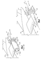
Figures 1 and2 , anaircraft 10 is schematically shown and includes contra-rotating open rotors (CROR) 14 mounted topylon 18 on each side of theaircraft fuselage 12. Awing 15 extends outward from each side of thefuselage 12 and a vertical T-tail stabilizer (and rudder(s)) 82 extends upward. In the T-tail horizontal stabilizer configuration, the horizontal stabilizer (and elevators) is mounted on top of the vertical stabilizer away from the engine's exhaust and propellers' turbulent wake. T-tail configurations are common for rear fuselage (i.e., empennage)-mounted engines as shown inFigure 1 and2 . TheCROR 14 includes two rotors, aforward rotor 20 and anaft rotor 22. Thefirst rotor 20 includes a first plurality ofpropeller blades 24 and the second rotor includes a second plurality ofpropeller blades 26. Each of therotors rotors - In this example, the
forward rotor 20 rotates in a clockwise direction and theaft rotor 22 rotates in a counter-clockwise direction. The disclosedexample propeller blades - In this disclosure, the term contra-rotation is utilized to describe a propulsion system where different rotors rotate about a common axis in different directions. The term counter-rotating is utilized in this disclosure to describe a propulsion system where propeller rotors on opposite sides of the
aircraft fuselage 12 rotate in opposite directions. - The example aircraft propulsion system includes a
pusher CROR 14 mounted within anacelle 16 supported by apylon 18 on either side of theaircraft fuselage 12. TheCROR 14 may be counter-rotated with respect to theCROR 14 on the opposite side of theaircraft 10, but may also be rotated in common directions regardless of the side of theaircraft 10 on which it is mounted. Both configurations are within the contemplation of this disclosure. Thenacelle 16 is spaced apart from thefuselage 12 by thepylon 18. - Referring to
Figure 2 , a prior art contra-rotatingopen rotor system 214 is shown and includes aturbine engine 230 supported within anacelle 216 spaced apart from theaircraft fuselage 212 by apylon 218. Theturbine engine 230 drives aforward rotor 220 including a forward plurality ofpropeller blades 224 and an aft rotor 222 including an aft plurality of propeller blades 226. - The
turbine engine 230 is of a significant weight and provides a large radial cross-section. Thepylon 218 is required to be of sufficient structural strength to support the weight and structure of theturbine engine 230. The required pylon structure can constrain the amount of spacing form theaircraft fuselage 212 and thereby limit the diameter of thepropeller blades 224, 226. Additionally, the radial cross-section of theturbine engine 230 can reduce the efficiency of thepropeller blades 224, 226. - Referring to
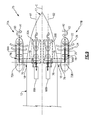
Figures 3 and4 , a disclosed distributedpropulsion system 28 includes theCROR 14 that is driven by a turbine engine 30 (as shown inFigure 4 ) supported within theaircraft fuselage 12. The distributedpropulsion system 28 includes a highly-efficient turbine engine 30 located along the aircraft longitudinal axis C inside theaircraft fuselage 12 near itstail cone 17. The highly-efficient gas turbine engine can be of any of the architectures such as but not limited to: turboshaft, turbojet, low-bypass turbofan, high-bypass turbofan, geared turbofan (GTF), etc. Theturbine engine 30 drives afirst CROR system 14A and asecond CROR system 14B mounted within correspondingnacelles aircraft fuselage 12. In this example, thefirst CROR system 14A rotates in afirst direction 60 and thesecond CROR system 14B rotates in asecond direction 62 opposite thefirst direction 60 about CROR axes A1 and A2, respectively. As appreciated, each of the first andsecond CROR systems aft rotors aircraft fuselage 12. Moreover, while the disclosed examples are CROR systems, it is within the contemplation of this disclosure to utilize a single propeller rotor rotating about a common axis. - The
example turbine engine 30 includes acompressor section 32 that feeds compressed air to combustor 38 where fuel is mixed with the air and ignited to generate a high energy gas flow. The high energy gas flow expands through atturbine section 40. Theturbine section 40 includes ahigh pressure turbine 42 and alow pressure turbine 44. Thehigh pressure turbine 42 is coupled to ahigh pressure compressor 36. Thelow pressure turbine 44 is coupled to alow pressure compressor 34 throughshaft 46. Although asingle shaft 46 is schematically shown, thehigh pressure compressor 36 is coupled to thehigh pressure turbine 42 through a second outer shaft (not shown) as is known. Although not shown inFig. 4 , a three-shaft (spool) gas turbine engine is also within the contemplated possibilities of this disclosure. A typical three-shaft turbine engine adds an intermediate shaft nestled concentrically between the high-pressure shaft and the low-pressure shaft. The intermediate shaft connects the intermediate-pressure turbine with the intermediate-pressure compressor. - The
shaft 46 is supported by bearingassembly 48 and output is transmitted to amain drive 52 that in turn drivessecondary drives differential gearbox 52 and the secondary drives areCROR engine gearboxes Intermediate shafts assemblies 50 extend from the maindifferential gearbox 52 and the drive smallerCROR engine gearboxes second CROR systems shaft system assemblies 58 within thenacelle aft rotors corresponding CROR system gearbox drive shaft system - Because the
turbine engine 30 is mounted within theaircraft fuselage 12 and not within eachnacelle nacelles corresponding CROR systems nacelles gearbox drive shaft system - The
example propulsion system 28 enables mounting of theCROR systems turbine engine 30 powering theCROR systems aircraft fuselage 12 instead of within thenacelle smaller nacelle pylon support structure 18 can be utilized. Thenacelles pylon 18 need be only large enough to contain the CROR drive system including theCROR gearbox shaft system assemblies 58 androtors nacelles fuselage 12 to enable the use oflarger diameter propellers - Referring to
Figure 5 anotherexample propulsion system 25 includes twoturbine engines directions turbine engines corresponding shaft main drive 51. In this example, themain drive 51 is adifferential gearbox 51 receiving driving input from each of the first andsecond turbine engines gas turbine engines propulsion system 28. Thegas turbine engines CROR systems differential gearbox 51. - Referring to
Figure 6 , anotherexample propulsion system 66 is shown where the main drive is agenerator 68 driven by agas turbine engine 30 that produces electric power and communicates that electric power to secondary drives that areelectric motors nacelles CROR system cables 70 to each correspondingelectric motor electric cables 70 to transmit power reduces complexity and overall system weight. Theelectric motors rotors different rotors - Referring to
Figure 7 anotherexample propulsion system 65 is shown where the main drive is agenerator 68 driven by agas turbine engine 30 that produces electric power and communicates that electric power toelectric motors aircraft fuselage 12. Theelectric motors CROR gearboxes nacelles shafts gearboxes CROR system cables 70 to each correspondingelectric motor electric motors gearbox rotors electric motors aircraft fuselage 12 provides for a very small cross-section of thenacelles - Referring to
Figure 8 , anotherexample propulsion system 75 includes two smallercompact turbine engines rear fuselage 12 and rotating about longitudinal axes B1 and B2, respectively. Both axes B1 and B2 are equidistant from the main central axis C. The axis B1 is on the starboard side, while the axis B2 is in the port side of theaircraft fuselage 12. Each of theturbine engines electric generator electric motor corresponding CROR system electric motors shaft systems rotors electric motors nacelles Fig. 8 ), or inside theaircraft fuselage 12 in an architecture similar to the one shown inFig. 7 ). Mounting theelectric motors aircraft fuselage 12 provides for a very small cross-section of thenacelles - The
example propulsion system 75 provides improved system redundancy and finer speed control by theelectric motors - Referring to
Figure 9 , the example propulsion systems enable windmilling of theCROR propellers turbine engines 30A/30B fail in flight. Windmilling of thepropellers electric motors multi-bladed CROR systems CROR systems rotatable rotors electric motor - During windmilling operation, the
propellers shaft systems electric motor example CROR system concentric shaft systems propellers electric generators solid line 76 and dashedline 78. Thesolid line 76 represents power generation from theforward rotor 20 andpropeller 24, and the dashedline 78 represents power generation from theaft rotor 22 andpropeller 26. - Referring to
Figures 10 and 11 , anaircraft 10 including thedistributive propulsion systems Figures 6 and8 respectively, provide for alternate positioning of theCROR system 14. Because power is transmitted throughcables 70 additional optional mounting locations of the example CROR systems become possible. Because the motors 72 are not mechanically coupled to theturbine engine 30, or a main gearbox, the CROR systems can be located further away from thefuselage 12. In one example shown inFigure 10 , the CROR system is mounted on a top surface of theaircraft wing 15. In another example shown inFigure 11 , the CROR system is mounted below theaircraft wing 15. Additionally, the CROR system enables lighter more efficient support structures because support is only required for the structures required to rotate the CROR system and not for the entire turbine engine. -
Figure 10 includes a horizontal stabilizer (with elevators) 85 that is modified to accommodate the mounting position of theCROR system 14. In this example, the horizontal stabilizer (with elevators) 85 is shortened and slightly angled upward such that is remains out of the airflow generated by theCROR system 14 toward the aft portion of theaircraft 10. The vertical stabilizer (with rudder(s)) 82 and the horizontal stabilizer (with elevators) 85 can be either of the conventional tail configuration or of the cruciform tail with no loss of functionality to the disclosed invention. In the conventional tail configuration, the horizontal stabilizer is mounted directly to the empennage (i.e., the rear fuselage). In the cruciform tail configuration, the horizontal stabilizer intersects the vertical stabilizer somewhere in the middle of the vertical stabilizer in a "cross"-like formation. -
Figure 11 includes a horizontal stabilizer 87 (with elevators) that is mounted directly to theaircraft fuselage 12 rear portion (empennage) in a conventional tail configuration including a vertical stabilizer (with rudder(s)) 82. The indicated location of the horizontal stabilizer (with elevators) 87 is such that it is spaced away from airflow and prop wash generated by theCROR system 14 mounted below the wing of theaircraft 10. - Referring to
Figure 12 , decoupling the gas generator from the CROR system enables additional optional engine mounting arrangements that can improve efficiency. An exampleengine mounting system 80 can be utilized with any of the example propulsion systems to thermodynamically improve operation. In the exampleengine mounting system 80 theturbine engine 30 is be mounted and operated in a "reverse flow" engine configuration. In the illustrated reverse flow engine configuration, thecompressor section 32 is mounted aft of theturbine section 40. Accordingly, thecompressor section 32 faces aft, theturbine section 40 faces forward and thepower shaft 46 extends forward from theturbine section 40. Airflow is communicated through anintake 84 near the base/root of the aircraft vertical stabilizer (with rudder(s)) 82 to the aft facingcompressor section 32, which moves forward, consecutively, through the combustor and turbine, and exhaust gases from theturbine section 40 are turned aft, and directed back through anoutlet 86 past the incoming airflow. - An
air intake passage 98 directs incoming air from theinlet 84 to thecompressor section 32 and anexhaust gas duct 100 directs exhaust gases to the upward-directed/orientedoutlet 86. Each of theintake passage 98 and exhaust passage are "S"-shaped to enable crossing flow through arecuperator 90. Therecuperator 90 utilizes the thermal difference between the hot engine exhaust gas and the cold inlet air flow. Therecuperator 90 utilizes the engine exhaust flow to preheat airflow to thecombustor 38. Accordingly, inlet airflow to thecombustor 38 is preheated by the hot exhaust. The preheated inlet air to thecombustor 38 improves the engine's overall thermodynamic efficiency by decreasing the required work done on the inlet air by thecompressor section 32. In addition, the preheated air entering thecombustor 38 facilitates the liquid fuel break-up and droplet atomization for improved combustor light-off, stability, and operational economy. The recuperator also lowers the temperature of the exhaust gas exiting through theoutlet 86, thus making the cooler exhaust less detectable by enemy heat-seeking infra-red (IR) missiles. Although a T-tail configuration is shown withvertical stabilizer 82 inFig. 12 , other tail architectures (i.e., such as the ones shown inFigures 10 and 11 , etc.) are also contemplated. In fact, since the main engine is inside the fuselage, the choice of tail configurations will depend on the actual placement of the CROR propulsion systems around the aircraft'sfuselage 12. - Although an example embodiment has been disclosed, a worker of ordinary skill in this art would recognize that certain modifications would come within the scope of this disclosure. For that reason, the following claims should be studied to determine the scope and content of this disclosure.
Claims (15)
- An aircraft propulsion system (14) comprising:a turbine engine (30) supported within an aircraft fuselage (12);a main drive (52; 51; 68; 68A, 68B) driven by the turbine engine (30);an open propeller system supported outside of the aircraft fuselage (12) separately from the turbine engine (30); anda secondary drive (56A, 56B; 72A, 72B) driven by the main drive for driving the open propeller system.
- The aircraft propulsion system as recited in claim 1, wherein the propeller system comprises a contra-rotating open rotor propeller system, wherein, optionally, the contra-rotating open rotor propeller system includes a forward propeller assembly (20) and an aft propeller assembly (22) having an outer diameter larger than the forward propeller assembly (20).
- The aircraft propulsion system as recited in claim 2, wherein the contra-rotating propeller system includes a gearbox for generating contra rotation of a or the forward propeller assembly (20) and an or the aft propeller assembly (22) about a common axis of rotation.
- The aircraft propulsion system as recited in any preceding claim, wherein the main drive comprises a main gearbox (52, 51) and the secondary drive comprises a propeller gearbox (56A, 56B) and the main gearbox (52, 51) is mechanically coupled to drive the propeller gearbox (56A, 56B).
- The aircraft propulsion system as recited in claim 4, wherein the main gearbox (52, 51) is supported within the aircraft fuselage (12) and is driven through a mechanical coupling to the turbine engine (30).
- The aircraft propulsion system as recited in claim 4 or 5, wherein the turbine engine comprises a first turbine engine (30A) and second turbine engine (30B) supported within the aircraft fuselage and each of the first and second turbine engines are coupled to drive the main gearbox (51).
- The aircraft propulsion system as recited in claim 6, wherein the first and second turbine engines (30A, 30B) are aligned along a common longitudinal axis.
- The aircraft propulsion system as recited in any preceding claim, wherein the main drive comprises a main electric generator (68) generating electrical power and the secondary drive comprises an electric motor (72) driven by the main electric generator.
- The aircraft propulsion system as recited in claim 8, wherein the propeller system comprises a first propeller system (14A) mounted on a first side of the aircraft fuselage (12) and a second propeller system (14B) mounted on a second side of the aircraft fuselage (12) and the secondary drive comprises first and second electric motors (72A, 72B) driven by the main electric generator (68) for driving a corresponding one of the first and second electric motors (72A, 72B; 67A, 67B).
- The aircraft propulsion system as recited in claim 9, wherein the first and second electric motors (67A, 67B) are mounted within the aircraft fuselage (12) and drive gearboxes (69A, 69B) mounted within a corresponding one of the first and second propeller systems (14A, 14B).
- The aircraft propulsion system as recited in claim 9 or 10, wherein the turbine engine comprises first and second turbine engines (30A, 30B) and the main generator comprises first and second generators (68A, 68B) driven by a corresponding one of the first and second turbine engines (30A, 30B), wherein each of the first and second generators (68A, 68B) drives a corresponding one of the first and second electric motors (72A, 72B; 67A, 67B).
- The aircraft propulsion system as recited in any preceding claim, including a nacelle assembly (16) spaced apart from the aircraft fuselage (12), wherein the secondary drive (56A, 56B; 72A, 72B) is disposed within nacelle assembly (16).
- An aircraft propulsion assembly comprising:a first contra-rotating open rotor propeller system (14A) supported on a first side of an aircraft fuselage (12);a second contra-rotating open rotor propeller system (14B) supported on a second side of the aircraft fuselage (12);a turbine engine (30) supported within the aircraft fuselage;a main power transfer system mechanically coupled to the turbine engine (30) and supported within the aircraft fuselage (12);a first drive driven by the main power transfer system for driving the first contra-rotating open rotor propeller system (14A); anda second drive driven by the main power transfer system for driving the second contra-rotating open rotor propeller system (14B); wherein, optionally, the main power transfer system comprises a main gearbox (51; 52) driven by the turbine engine (30) through a main shaft, and/or wherein, optionally, the first drive and the second drive comprise gearboxes mechanically coupled to the or a main gearbox (51, 52) and configured to generate for counter rotation of the corresponding first contra-rotating open rotor propeller assembly and the second contra-rotating open rotor propeller assembly.
- The aircraft propulsion system as recited in claim 13, wherein the main power transfer system comprises a main generator (68) and the first drive and the second drive comprise first and second electric motors (72A, 72B) electrically coupled to the main generator (68), and wherein, optionally, the turbine engine comprises a first turbine engine (30A) and a second turbine engine (30B) and the main generator (68) comprises a first generator (68A) driven by the first turbine engine (30A) and a second generator (30B) driven by the second turbine engine (30B).
- The aircraft propulsion system as recited in claim 13 or 14, wherein the turbine engine comprises a reverse flow turbine engine with a compressor (32) communicating compressed air forward to a combustor (38) to generate high energy exhaust gases forward to a turbine (40) that is configured to drive the compressor, and optionally including a recuperator (90) in communication with incoming airflow and outgoing exhaust gas flow.
Applications Claiming Priority (1)
| Application Number | Priority Date | Filing Date | Title |
|---|---|---|---|
| US201461924142P | 2014-01-06 | 2014-01-06 |
Publications (2)
| Publication Number | Publication Date |
|---|---|
| EP2930114A1 true EP2930114A1 (en) | 2015-10-14 |
| EP2930114B1 EP2930114B1 (en) | 2016-11-02 |
Family
ID=52338983
Family Applications (1)
| Application Number | Title | Priority Date | Filing Date |
|---|---|---|---|
| EP15150203.6A Active EP2930114B1 (en) | 2014-01-06 | 2015-01-06 | Contra-rotating open rotor distributed propulsion system |
Country Status (2)
| Country | Link |
|---|---|
| US (1) | US9701395B2 (en) |
| EP (1) | EP2930114B1 (en) |
Cited By (4)
| Publication number | Priority date | Publication date | Assignee | Title |
|---|---|---|---|---|
| WO2017109430A1 (en) * | 2015-12-23 | 2017-06-29 | Safran Aircraft Engines | Turbomachine with reverse clipping propeller |
| GB2551552A (en) * | 2016-06-22 | 2017-12-27 | Rolls Royce Plc | Gas turbine engine |
| WO2018103762A1 (en) | 2017-01-06 | 2018-06-14 | 西北工业大学 | Distributed propulsion system |
| EP3800125A1 (en) * | 2019-10-02 | 2021-04-07 | The Boeing Company | Dual hybrid propulsion system for an aircraft having a cross-connecting clutch |
Families Citing this family (33)
| Publication number | Priority date | Publication date | Assignee | Title |
|---|---|---|---|---|
| US10773808B2 (en) | 2015-06-04 | 2020-09-15 | Hamilton Sunstrand Corporation | Method for designing an ECS |
| US20170057649A1 (en) * | 2015-08-27 | 2017-03-02 | Edward C. Rice | Integrated aircraft propulsion system |
| US10723440B2 (en) | 2016-03-23 | 2020-07-28 | Amazon Technologies, Inc. | Aerial vehicle with different propeller blade configurations |
| US10526070B2 (en) | 2016-03-23 | 2020-01-07 | Amazon Technologies, Inc. | Aerial vehicle propulsion mechanism with coaxially aligned propellers |
| US11305874B2 (en) | 2016-03-23 | 2022-04-19 | Amazon Technologies, Inc. | Aerial vehicle adaptable propeller blades |
| US10399666B2 (en) | 2016-03-23 | 2019-09-03 | Amazon Technologies, Inc. | Aerial vehicle propulsion mechanism with coaxially aligned and independently rotatable propellers |
| US10583914B2 (en) | 2016-03-23 | 2020-03-10 | Amazon Technologies, Inc. | Telescoping propeller blades for aerial vehicles |
| US10392120B2 (en) | 2016-04-19 | 2019-08-27 | General Electric Company | Propulsion engine for an aircraft |
| FR3050721B1 (en) * | 2016-04-28 | 2018-04-13 | Airbus Operations | AIRCRAFT ENGINE ASSEMBLY COMPRISING A MATTRESS ATTACK EDGE INTEGRATED WITH AN ANNULAR ROW OF OUTER CARRIER OUTPUT GUIDELINES |
| US10676198B2 (en) | 2016-06-02 | 2020-06-09 | Rolls-Royce Corporation | Distributed propulsion systems |
| US20180163664A1 (en) * | 2016-12-08 | 2018-06-14 | United Technologies Corporation | Concentric shafts driving adjacent fans for aircraft propulsion |
| US10273019B2 (en) | 2017-03-06 | 2019-04-30 | Rolls-Royce Corporation | Distributed propulsion system power unit control |
| US10689082B2 (en) | 2017-04-12 | 2020-06-23 | Rolls-Royce North American Technologies, Inc. | Mechanically and electrically distributed propulsion |
| US10723470B2 (en) * | 2017-06-12 | 2020-07-28 | Raytheon Technologies Corporation | Aft fan counter-rotating turbine engine |
| US11111029B2 (en) * | 2017-07-28 | 2021-09-07 | The Boeing Company | System and method for operating a boundary layer ingestion fan |
| US10961850B2 (en) | 2017-09-19 | 2021-03-30 | General Electric Company | Rotatable torque frame for gas turbine engine |
| US11008883B2 (en) | 2017-09-20 | 2021-05-18 | General Electric Company | Turbomachine with a gearbox and integrated electric machine assembly |
| US10906657B2 (en) * | 2018-06-19 | 2021-02-02 | Raytheon Technologies Corporation | Aircraft system with distributed propulsion |
| US10759545B2 (en) | 2018-06-19 | 2020-09-01 | Raytheon Technologies Corporation | Hybrid electric aircraft system with distributed propulsion |
| US11156128B2 (en) | 2018-08-22 | 2021-10-26 | General Electric Company | Embedded electric machine |
| US11142330B2 (en) * | 2018-08-30 | 2021-10-12 | Aurora Flight Sciences Corporation | Mechanically-distributed propulsion drivetrain and architecture |
| US20200140062A1 (en) * | 2018-11-01 | 2020-05-07 | Eviation Tech Ltd | Electric propeller and ducted fan propulsion unit |
| FR3088903B1 (en) * | 2018-11-22 | 2020-10-30 | Safran | Propulsion system of an aircraft and method of operating such a system |
| US11267577B2 (en) | 2019-12-06 | 2022-03-08 | General Electric Company | Aircraft having an engine wing assembly |
| CN114762229B (en) * | 2020-01-17 | 2026-04-14 | 小鹰公司 | Non-reaction free-turning motor with double propellers |
| CA3198792A1 (en) * | 2020-11-13 | 2022-05-19 | Michael VON BERTOUCH | Aerial vehicles |
| US12145734B2 (en) | 2020-12-28 | 2024-11-19 | Hamilton Sundstrand Corporation | Hybrid propulsion systems |
| US11428160B2 (en) | 2020-12-31 | 2022-08-30 | General Electric Company | Gas turbine engine with interdigitated turbine and gear assembly |
| US12397889B2 (en) | 2021-04-21 | 2025-08-26 | Sharrow Engineering Llc | Duo-propellers and single propellers |
| US12149154B2 (en) | 2021-07-22 | 2024-11-19 | General Electric Company | Electric machine having a hybrid insulative-conductive manifold |
| JP7810965B2 (en) * | 2022-04-12 | 2026-02-04 | 株式会社石川エナジーリサーチ | flight equipment |
| US12480449B2 (en) | 2022-08-22 | 2025-11-25 | General Electric Company | Propulsion system including an electric machine for starting a gas turbine engine |
| US12448112B1 (en) | 2024-08-13 | 2025-10-21 | General Electric Company | Power generation and transfer using variable-pitch propeller |
Citations (4)
| Publication number | Priority date | Publication date | Assignee | Title |
|---|---|---|---|---|
| EP0272822A1 (en) * | 1986-12-03 | 1988-06-29 | Short Brothers Plc | Aircraft propulsion |
| US6279852B1 (en) * | 1997-04-24 | 2001-08-28 | Societe Nationale d'Etude et de Construction de Moteurs d'Aviation “SNECMA” | Drive system for a propeller driven transport aircraft |
| US20120128487A1 (en) * | 2010-11-24 | 2012-05-24 | David John Howard Eames | Remote shaft driven open rotor propulsion system with electrical power generation |
| GB2497136A (en) * | 2011-12-02 | 2013-06-05 | Eads Uk Ltd | Electric distributed propulsion |
Family Cites Families (21)
| Publication number | Priority date | Publication date | Assignee | Title |
|---|---|---|---|---|
| GB443763A (en) * | 1934-10-28 | 1936-03-05 | Makoto Shiga | Compound screw propellers for aircraft |
| US2581320A (en) | 1945-07-20 | 1952-01-01 | Douglas Aircraft Co Inc | Multiengine contra-rotating propeller drive transmission |
| US3485462A (en) | 1967-08-28 | 1969-12-23 | Spence William | Aircraft propeller and jet drive |
| GB2173863B (en) | 1985-04-17 | 1989-07-19 | Rolls Royce Plc | A propeller module for an aero gas turbine engine |
| US7643928B2 (en) | 2004-01-05 | 2010-01-05 | Bombardier Transportation Gmbh | System and method for controlling the speed of a gas turbine engine |
| FR2871137B1 (en) | 2004-06-03 | 2006-09-08 | Airbus France Sas | PROPULSION SYSTEM FOR AIRCRAFT COMPRISING FOUR PROPULSIVE PROPELLER ENGINES |
| US7540450B2 (en) * | 2004-07-16 | 2009-06-02 | Pratt & Whitney Canada Corp. | Aircraft propulsion system |
| FR2892705B1 (en) | 2005-11-03 | 2009-04-24 | Airbus France Sas | AIRCRAFT WITH REDUCED ENVIRONMENTAL IMPACT. |
| US7752834B2 (en) * | 2006-10-25 | 2010-07-13 | United Technologies Corporation | Aircraft propulsion systems |
| US20080099632A1 (en) | 2006-10-25 | 2008-05-01 | United Technologies Corporation | Aircraft airframe architectures |
| DE102006056355A1 (en) * | 2006-11-29 | 2008-06-05 | Airbus Deutschland Gmbh | Drive device for aircraft, has energy converter e.g. gas turbine, for providing operating power of drive unit by two different fuels such as kerosene and hydrogen, and drive unit generating feed rate by operating power |
| CN101652286B (en) | 2007-01-18 | 2013-12-18 | 保罗·E·阿尔托恩 | Rotorcraft Power and Propulsion Systems |
| GB0816636D0 (en) | 2008-09-12 | 2008-10-22 | Rolls Royce Plc | Controlling rotor overspeed |
| DE102008062813A1 (en) * | 2008-12-23 | 2010-07-15 | Rolls-Royce Deutschland Ltd & Co Kg | Airplane with a stern-propeller engine arrangement |
| DE102009007013A1 (en) | 2009-01-31 | 2010-08-12 | Deutsches Zentrum für Luft- und Raumfahrt e.V. | Engine, especially CROR propulsion, for an aircraft |
| DE102009010524A1 (en) | 2009-02-25 | 2010-09-02 | Rolls-Royce Deutschland Ltd & Co Kg | Turboprop drive with pressure propeller |
| US8176725B2 (en) * | 2009-09-09 | 2012-05-15 | United Technologies Corporation | Reversed-flow core for a turbofan with a fan drive gear system |
| FR2955085B1 (en) | 2010-01-08 | 2011-12-23 | Snecma | SYSTEM FOR CONTRAROTATIVE PROPELLERS FOR AIRCRAFT TURBOMACHINE |
| US9718536B2 (en) | 2010-05-18 | 2017-08-01 | Hamilton Sundstrand Corporation | Counter-rotating open-rotor (CROR) |
| US8740565B2 (en) | 2011-08-12 | 2014-06-03 | Hamilton Sundstrand Corporation | Modular counter rotating propeller system |
| US8708274B2 (en) * | 2011-09-09 | 2014-04-29 | United Technologies Corporation | Transverse mounted gas turbine engine |
-
2014
- 2014-12-22 US US14/578,975 patent/US9701395B2/en active Active
-
2015
- 2015-01-06 EP EP15150203.6A patent/EP2930114B1/en active Active
Patent Citations (4)
| Publication number | Priority date | Publication date | Assignee | Title |
|---|---|---|---|---|
| EP0272822A1 (en) * | 1986-12-03 | 1988-06-29 | Short Brothers Plc | Aircraft propulsion |
| US6279852B1 (en) * | 1997-04-24 | 2001-08-28 | Societe Nationale d'Etude et de Construction de Moteurs d'Aviation “SNECMA” | Drive system for a propeller driven transport aircraft |
| US20120128487A1 (en) * | 2010-11-24 | 2012-05-24 | David John Howard Eames | Remote shaft driven open rotor propulsion system with electrical power generation |
| GB2497136A (en) * | 2011-12-02 | 2013-06-05 | Eads Uk Ltd | Electric distributed propulsion |
Cited By (7)
| Publication number | Priority date | Publication date | Assignee | Title |
|---|---|---|---|---|
| WO2017109430A1 (en) * | 2015-12-23 | 2017-06-29 | Safran Aircraft Engines | Turbomachine with reverse clipping propeller |
| FR3046135A1 (en) * | 2015-12-23 | 2017-06-30 | Snecma | REVERSE CLIPPING PROPELLER TURBOMACHINE |
| GB2551552A (en) * | 2016-06-22 | 2017-12-27 | Rolls Royce Plc | Gas turbine engine |
| GB2551552B (en) * | 2016-06-22 | 2018-10-03 | Rolls Royce Plc | An aircraft gas turbine engine comprising non-coaxial propulsors driven by an engine core comprising two axially spaced core modules |
| WO2018103762A1 (en) | 2017-01-06 | 2018-06-14 | 西北工业大学 | Distributed propulsion system |
| EP3800125A1 (en) * | 2019-10-02 | 2021-04-07 | The Boeing Company | Dual hybrid propulsion system for an aircraft having a cross-connecting clutch |
| US11286054B2 (en) | 2019-10-02 | 2022-03-29 | The Boeing Company | Dual hybrid propulsion system for an aircraft having a cross-connecting clutch |
Also Published As
| Publication number | Publication date |
|---|---|
| EP2930114B1 (en) | 2016-11-02 |
| US20150284071A1 (en) | 2015-10-08 |
| US9701395B2 (en) | 2017-07-11 |
Similar Documents
| Publication | Publication Date | Title |
|---|---|---|
| EP2930114B1 (en) | Contra-rotating open rotor distributed propulsion system | |
| US20240368997A1 (en) | Unducted thrust producing system architecture | |
| US11655767B2 (en) | Gearbox for an engine | |
| US8256709B2 (en) | Aircraft with tail propeller-engine layout | |
| US8562284B2 (en) | Propulsive fan system | |
| US20170369179A1 (en) | Gas turbine engine | |
| US8943796B2 (en) | Variable cycle turbine engine | |
| EP2966266A1 (en) | Two-part gas turbine engine | |
| US20170268430A1 (en) | Engine bleed system with turbo-compressor | |
| US11821360B2 (en) | Aircraft propulsion system and aircraft powered by such a propulsion system built into the rear of an aircraft fuselage | |
| US11946437B2 (en) | Variable pitch fans for turbomachinery engines | |
| US20160076444A1 (en) | Multi-fan engine with an enhanced power transmission | |
| EP4389607B1 (en) | Hybrid aircraft propulsion system with remotely located electric machine | |
| EP4306422B1 (en) | Aircraft propulsion system with intermittent combustion engine(s) | |
| EP4567263A1 (en) | Compressed air system for aircraft | |
| EP4509703A1 (en) | Aircraft powerplant with electric powertrain | |
| US20170057649A1 (en) | Integrated aircraft propulsion system | |
| US12385434B2 (en) | Aircraft powerplant with boosted gas turbine engine | |
| US20260070667A1 (en) | Aircraft with an unducted fan propulsor | |
| EP4321746A1 (en) | Variable pitch fans for turbomachinery engines | |
| RU2705857C1 (en) | Helicopter power plant | |
| EP4282764A1 (en) | Aircraft propulsion system with adjustable thrust propulsor | |
| US20180244396A1 (en) | Drive system arrangement for rotorcraft | |
| CA3257447A1 (en) | Compressed air system for aircraft |
Legal Events
| Date | Code | Title | Description |
|---|---|---|---|
| PUAI | Public reference made under article 153(3) epc to a published international application that has entered the european phase |
Free format text: ORIGINAL CODE: 0009012 |
|
| AK | Designated contracting states |
Kind code of ref document: A1 Designated state(s): AL AT BE BG CH CY CZ DE DK EE ES FI FR GB GR HR HU IE IS IT LI LT LU LV MC MK MT NL NO PL PT RO RS SE SI SK SM TR |
|
| AX | Request for extension of the european patent |
Extension state: BA ME |
|
| GRAP | Despatch of communication of intention to grant a patent |
Free format text: ORIGINAL CODE: EPIDOSNIGR1 |
|
| 17P | Request for examination filed |
Effective date: 20160414 |
|
| RBV | Designated contracting states (corrected) |
Designated state(s): AL AT BE BG CH CY CZ DE DK EE ES FI FR GB GR HR HU IE IS IT LI LT LU LV MC MK MT NL NO PL PT RO RS SE SI SK SM TR |
|
| RIC1 | Information provided on ipc code assigned before grant |
Ipc: B64D 27/14 20060101AFI20160429BHEP |
|
| INTG | Intention to grant announced |
Effective date: 20160523 |
|
| GRAS | Grant fee paid |
Free format text: ORIGINAL CODE: EPIDOSNIGR3 |
|
| GRAA | (expected) grant |
Free format text: ORIGINAL CODE: 0009210 |
|
| RAP1 | Party data changed (applicant data changed or rights of an application transferred) |
Owner name: UNITED TECHNOLOGIES CORPORATION |
|
| AK | Designated contracting states |
Kind code of ref document: B1 Designated state(s): AL AT BE BG CH CY CZ DE DK EE ES FI FR GB GR HR HU IE IS IT LI LT LU LV MC MK MT NL NO PL PT RO RS SE SI SK SM TR |
|
| REG | Reference to a national code |
Ref country code: GB Ref legal event code: FG4D |
|
| REG | Reference to a national code |
Ref country code: AT Ref legal event code: REF Ref document number: 841555 Country of ref document: AT Kind code of ref document: T Effective date: 20161115 Ref country code: CH Ref legal event code: EP |
|
| REG | Reference to a national code |
Ref country code: IE Ref legal event code: FG4D |
|
| REG | Reference to a national code |
Ref country code: DE Ref legal event code: R096 Ref document number: 602015000557 Country of ref document: DE |
|
| REG | Reference to a national code |
Ref country code: FR Ref legal event code: PLFP Year of fee payment: 3 |
|
| PG25 | Lapsed in a contracting state [announced via postgrant information from national office to epo] |
Ref country code: LV Free format text: LAPSE BECAUSE OF FAILURE TO SUBMIT A TRANSLATION OF THE DESCRIPTION OR TO PAY THE FEE WITHIN THE PRESCRIBED TIME-LIMIT Effective date: 20161102 |
|
| REG | Reference to a national code |
Ref country code: NL Ref legal event code: MP Effective date: 20161102 |
|
| REG | Reference to a national code |
Ref country code: LT Ref legal event code: MG4D |
|
| REG | Reference to a national code |
Ref country code: AT Ref legal event code: MK05 Ref document number: 841555 Country of ref document: AT Kind code of ref document: T Effective date: 20161102 |
|
| PG25 | Lapsed in a contracting state [announced via postgrant information from national office to epo] |
Ref country code: NL Free format text: LAPSE BECAUSE OF FAILURE TO SUBMIT A TRANSLATION OF THE DESCRIPTION OR TO PAY THE FEE WITHIN THE PRESCRIBED TIME-LIMIT Effective date: 20161102 Ref country code: GR Free format text: LAPSE BECAUSE OF FAILURE TO SUBMIT A TRANSLATION OF THE DESCRIPTION OR TO PAY THE FEE WITHIN THE PRESCRIBED TIME-LIMIT Effective date: 20170203 Ref country code: LT Free format text: LAPSE BECAUSE OF FAILURE TO SUBMIT A TRANSLATION OF THE DESCRIPTION OR TO PAY THE FEE WITHIN THE PRESCRIBED TIME-LIMIT Effective date: 20161102 Ref country code: SE Free format text: LAPSE BECAUSE OF FAILURE TO SUBMIT A TRANSLATION OF THE DESCRIPTION OR TO PAY THE FEE WITHIN THE PRESCRIBED TIME-LIMIT Effective date: 20161102 Ref country code: NO Free format text: LAPSE BECAUSE OF FAILURE TO SUBMIT A TRANSLATION OF THE DESCRIPTION OR TO PAY THE FEE WITHIN THE PRESCRIBED TIME-LIMIT Effective date: 20170202 |
|
| PG25 | Lapsed in a contracting state [announced via postgrant information from national office to epo] |
Ref country code: FI Free format text: LAPSE BECAUSE OF FAILURE TO SUBMIT A TRANSLATION OF THE DESCRIPTION OR TO PAY THE FEE WITHIN THE PRESCRIBED TIME-LIMIT Effective date: 20161102 Ref country code: AT Free format text: LAPSE BECAUSE OF FAILURE TO SUBMIT A TRANSLATION OF THE DESCRIPTION OR TO PAY THE FEE WITHIN THE PRESCRIBED TIME-LIMIT Effective date: 20161102 Ref country code: BE Free format text: LAPSE BECAUSE OF NON-PAYMENT OF DUE FEES Effective date: 20170131 Ref country code: RS Free format text: LAPSE BECAUSE OF FAILURE TO SUBMIT A TRANSLATION OF THE DESCRIPTION OR TO PAY THE FEE WITHIN THE PRESCRIBED TIME-LIMIT Effective date: 20161102 Ref country code: PL Free format text: LAPSE BECAUSE OF FAILURE TO SUBMIT A TRANSLATION OF THE DESCRIPTION OR TO PAY THE FEE WITHIN THE PRESCRIBED TIME-LIMIT Effective date: 20161102 Ref country code: IS Free format text: LAPSE BECAUSE OF FAILURE TO SUBMIT A TRANSLATION OF THE DESCRIPTION OR TO PAY THE FEE WITHIN THE PRESCRIBED TIME-LIMIT Effective date: 20170302 Ref country code: PT Free format text: LAPSE BECAUSE OF FAILURE TO SUBMIT A TRANSLATION OF THE DESCRIPTION OR TO PAY THE FEE WITHIN THE PRESCRIBED TIME-LIMIT Effective date: 20170302 Ref country code: HR Free format text: LAPSE BECAUSE OF FAILURE TO SUBMIT A TRANSLATION OF THE DESCRIPTION OR TO PAY THE FEE WITHIN THE PRESCRIBED TIME-LIMIT Effective date: 20161102 Ref country code: ES Free format text: LAPSE BECAUSE OF FAILURE TO SUBMIT A TRANSLATION OF THE DESCRIPTION OR TO PAY THE FEE WITHIN THE PRESCRIBED TIME-LIMIT Effective date: 20161102 |
|
| REG | Reference to a national code |
Ref country code: DE Ref legal event code: R082 Ref document number: 602015000557 Country of ref document: DE Representative=s name: SCHMITT-NILSON SCHRAUD WAIBEL WOHLFROM PATENTA, DE |
|
| PG25 | Lapsed in a contracting state [announced via postgrant information from national office to epo] |
Ref country code: SK Free format text: LAPSE BECAUSE OF FAILURE TO SUBMIT A TRANSLATION OF THE DESCRIPTION OR TO PAY THE FEE WITHIN THE PRESCRIBED TIME-LIMIT Effective date: 20161102 Ref country code: EE Free format text: LAPSE BECAUSE OF FAILURE TO SUBMIT A TRANSLATION OF THE DESCRIPTION OR TO PAY THE FEE WITHIN THE PRESCRIBED TIME-LIMIT Effective date: 20161102 Ref country code: DK Free format text: LAPSE BECAUSE OF FAILURE TO SUBMIT A TRANSLATION OF THE DESCRIPTION OR TO PAY THE FEE WITHIN THE PRESCRIBED TIME-LIMIT Effective date: 20161102 Ref country code: CZ Free format text: LAPSE BECAUSE OF FAILURE TO SUBMIT A TRANSLATION OF THE DESCRIPTION OR TO PAY THE FEE WITHIN THE PRESCRIBED TIME-LIMIT Effective date: 20161102 Ref country code: RO Free format text: LAPSE BECAUSE OF FAILURE TO SUBMIT A TRANSLATION OF THE DESCRIPTION OR TO PAY THE FEE WITHIN THE PRESCRIBED TIME-LIMIT Effective date: 20161102 |
|
| REG | Reference to a national code |
Ref country code: DE Ref legal event code: R097 Ref document number: 602015000557 Country of ref document: DE |
|
| PG25 | Lapsed in a contracting state [announced via postgrant information from national office to epo] |
Ref country code: IT Free format text: LAPSE BECAUSE OF FAILURE TO SUBMIT A TRANSLATION OF THE DESCRIPTION OR TO PAY THE FEE WITHIN THE PRESCRIBED TIME-LIMIT Effective date: 20161102 Ref country code: BG Free format text: LAPSE BECAUSE OF FAILURE TO SUBMIT A TRANSLATION OF THE DESCRIPTION OR TO PAY THE FEE WITHIN THE PRESCRIBED TIME-LIMIT Effective date: 20170202 Ref country code: SM Free format text: LAPSE BECAUSE OF FAILURE TO SUBMIT A TRANSLATION OF THE DESCRIPTION OR TO PAY THE FEE WITHIN THE PRESCRIBED TIME-LIMIT Effective date: 20161102 Ref country code: BE Free format text: LAPSE BECAUSE OF FAILURE TO SUBMIT A TRANSLATION OF THE DESCRIPTION OR TO PAY THE FEE WITHIN THE PRESCRIBED TIME-LIMIT Effective date: 20161102 |
|
| PLBE | No opposition filed within time limit |
Free format text: ORIGINAL CODE: 0009261 |
|
| STAA | Information on the status of an ep patent application or granted ep patent |
Free format text: STATUS: NO OPPOSITION FILED WITHIN TIME LIMIT |
|
| PG25 | Lapsed in a contracting state [announced via postgrant information from national office to epo] |
Ref country code: MC Free format text: LAPSE BECAUSE OF FAILURE TO SUBMIT A TRANSLATION OF THE DESCRIPTION OR TO PAY THE FEE WITHIN THE PRESCRIBED TIME-LIMIT Effective date: 20161102 |
|
| 26N | No opposition filed |
Effective date: 20170803 |
|
| REG | Reference to a national code |
Ref country code: IE Ref legal event code: MM4A |
|
| PG25 | Lapsed in a contracting state [announced via postgrant information from national office to epo] |
Ref country code: LU Free format text: LAPSE BECAUSE OF NON-PAYMENT OF DUE FEES Effective date: 20170106 Ref country code: SI Free format text: LAPSE BECAUSE OF FAILURE TO SUBMIT A TRANSLATION OF THE DESCRIPTION OR TO PAY THE FEE WITHIN THE PRESCRIBED TIME-LIMIT Effective date: 20161102 |
|
| REG | Reference to a national code |
Ref country code: FR Ref legal event code: PLFP Year of fee payment: 4 |
|
| PG25 | Lapsed in a contracting state [announced via postgrant information from national office to epo] |
Ref country code: IE Free format text: LAPSE BECAUSE OF NON-PAYMENT OF DUE FEES Effective date: 20170106 |
|
| REG | Reference to a national code |
Ref country code: CH Ref legal event code: PL |
|
| PG25 | Lapsed in a contracting state [announced via postgrant information from national office to epo] |
Ref country code: MT Free format text: LAPSE BECAUSE OF NON-PAYMENT OF DUE FEES Effective date: 20170106 |
|
| PG25 | Lapsed in a contracting state [announced via postgrant information from national office to epo] |
Ref country code: LI Free format text: LAPSE BECAUSE OF NON-PAYMENT OF DUE FEES Effective date: 20180131 Ref country code: CH Free format text: LAPSE BECAUSE OF NON-PAYMENT OF DUE FEES Effective date: 20180131 |
|
| PG25 | Lapsed in a contracting state [announced via postgrant information from national office to epo] |
Ref country code: HU Free format text: LAPSE BECAUSE OF FAILURE TO SUBMIT A TRANSLATION OF THE DESCRIPTION OR TO PAY THE FEE WITHIN THE PRESCRIBED TIME-LIMIT; INVALID AB INITIO Effective date: 20150106 |
|
| PG25 | Lapsed in a contracting state [announced via postgrant information from national office to epo] |
Ref country code: CY Free format text: LAPSE BECAUSE OF FAILURE TO SUBMIT A TRANSLATION OF THE DESCRIPTION OR TO PAY THE FEE WITHIN THE PRESCRIBED TIME-LIMIT Effective date: 20161102 |
|
| PG25 | Lapsed in a contracting state [announced via postgrant information from national office to epo] |
Ref country code: MK Free format text: LAPSE BECAUSE OF FAILURE TO SUBMIT A TRANSLATION OF THE DESCRIPTION OR TO PAY THE FEE WITHIN THE PRESCRIBED TIME-LIMIT Effective date: 20161102 |
|
| PG25 | Lapsed in a contracting state [announced via postgrant information from national office to epo] |
Ref country code: TR Free format text: LAPSE BECAUSE OF FAILURE TO SUBMIT A TRANSLATION OF THE DESCRIPTION OR TO PAY THE FEE WITHIN THE PRESCRIBED TIME-LIMIT Effective date: 20161102 |
|
| PG25 | Lapsed in a contracting state [announced via postgrant information from national office to epo] |
Ref country code: AL Free format text: LAPSE BECAUSE OF FAILURE TO SUBMIT A TRANSLATION OF THE DESCRIPTION OR TO PAY THE FEE WITHIN THE PRESCRIBED TIME-LIMIT Effective date: 20161102 |
|
| REG | Reference to a national code |
Ref country code: DE Ref legal event code: R081 Ref document number: 602015000557 Country of ref document: DE Owner name: RAYTHEON TECHNOLOGIES CORPORATION (N.D.GES.D.S, US Free format text: FORMER OWNER: UNITED TECHNOLOGIES CORPORATION, FARMINGTON, CONN., US Ref country code: DE Ref legal event code: R081 Ref document number: 602015000557 Country of ref document: DE Owner name: RTX CORPORATION (N.D.GES.D. STAATES DELAWARE),, US Free format text: FORMER OWNER: UNITED TECHNOLOGIES CORPORATION, FARMINGTON, CONN., US |
|
| P01 | Opt-out of the competence of the unified patent court (upc) registered |
Effective date: 20230520 |
|
| REG | Reference to a national code |
Ref country code: DE Ref legal event code: R081 Ref document number: 602015000557 Country of ref document: DE Owner name: RTX CORPORATION (N.D.GES.D. STAATES DELAWARE),, US Free format text: FORMER OWNER: RAYTHEON TECHNOLOGIES CORPORATION (N.D.GES.D.STAATES DELAWARE), ARLINGTON, VA, US |
|
| PGFP | Annual fee paid to national office [announced via postgrant information from national office to epo] |
Ref country code: GB Payment date: 20251220 Year of fee payment: 12 |
|
| PGFP | Annual fee paid to national office [announced via postgrant information from national office to epo] |
Ref country code: FR Payment date: 20251217 Year of fee payment: 12 |
|
| PGFP | Annual fee paid to national office [announced via postgrant information from national office to epo] |
Ref country code: DE Payment date: 20251217 Year of fee payment: 12 |