EP2930075A1 - Electronic parking brake actuator - Google Patents
Electronic parking brake actuator Download PDFInfo
- Publication number
- EP2930075A1 EP2930075A1 EP15162926.8A EP15162926A EP2930075A1 EP 2930075 A1 EP2930075 A1 EP 2930075A1 EP 15162926 A EP15162926 A EP 15162926A EP 2930075 A1 EP2930075 A1 EP 2930075A1
- Authority
- EP
- European Patent Office
- Prior art keywords
- gear
- parking brake
- ring gear
- brake actuator
- motor
- Prior art date
- Legal status (The legal status is an assumption and is not a legal conclusion. Google has not performed a legal analysis and makes no representation as to the accuracy of the status listed.)
- Granted
Links
Images



Classifications
-
- F—MECHANICAL ENGINEERING; LIGHTING; HEATING; WEAPONS; BLASTING
- F16—ENGINEERING ELEMENTS AND UNITS; GENERAL MEASURES FOR PRODUCING AND MAINTAINING EFFECTIVE FUNCTIONING OF MACHINES OR INSTALLATIONS; THERMAL INSULATION IN GENERAL
- F16H—GEARING
- F16H63/00—Control outputs from the control unit to change-speed- or reversing-gearings for conveying rotary motion or to other devices than the final output mechanism
- F16H63/02—Final output mechanisms therefor; Actuating means for the final output mechanisms
- F16H63/30—Constructional features of the final output mechanisms
- F16H63/34—Locking or disabling mechanisms
- F16H63/3416—Parking lock mechanisms or brakes in the transmission
- F16H63/3458—Parking lock mechanisms or brakes in the transmission with electric actuating means, e.g. shift by wire
- F16H63/3466—Parking lock mechanisms or brakes in the transmission with electric actuating means, e.g. shift by wire using electric motors
-
- B—PERFORMING OPERATIONS; TRANSPORTING
- B60—VEHICLES IN GENERAL
- B60T—VEHICLE BRAKE CONTROL SYSTEMS OR PARTS THEREOF; BRAKE CONTROL SYSTEMS OR PARTS THEREOF, IN GENERAL; ARRANGEMENT OF BRAKING ELEMENTS ON VEHICLES IN GENERAL; PORTABLE DEVICES FOR PREVENTING UNWANTED MOVEMENT OF VEHICLES; VEHICLE MODIFICATIONS TO FACILITATE COOLING OF BRAKES
- B60T13/00—Transmitting braking action from initiating means to ultimate brake actuator with power assistance or drive; Brake systems incorporating such transmitting means, e.g. air-pressure brake systems
- B60T13/74—Transmitting braking action from initiating means to ultimate brake actuator with power assistance or drive; Brake systems incorporating such transmitting means, e.g. air-pressure brake systems with electrical assistance or drive
- B60T13/746—Transmitting braking action from initiating means to ultimate brake actuator with power assistance or drive; Brake systems incorporating such transmitting means, e.g. air-pressure brake systems with electrical assistance or drive and mechanical transmission of the braking action
-
- F—MECHANICAL ENGINEERING; LIGHTING; HEATING; WEAPONS; BLASTING
- F16—ENGINEERING ELEMENTS AND UNITS; GENERAL MEASURES FOR PRODUCING AND MAINTAINING EFFECTIVE FUNCTIONING OF MACHINES OR INSTALLATIONS; THERMAL INSULATION IN GENERAL
- F16D—COUPLINGS FOR TRANSMITTING ROTATION; CLUTCHES; BRAKES
- F16D65/00—Parts or details
- F16D65/14—Actuating mechanisms for brakes; Means for initiating operation at a predetermined position
- F16D65/16—Actuating mechanisms for brakes; Means for initiating operation at a predetermined position arranged in or on the brake
-
- F—MECHANICAL ENGINEERING; LIGHTING; HEATING; WEAPONS; BLASTING
- F16—ENGINEERING ELEMENTS AND UNITS; GENERAL MEASURES FOR PRODUCING AND MAINTAINING EFFECTIVE FUNCTIONING OF MACHINES OR INSTALLATIONS; THERMAL INSULATION IN GENERAL
- F16H—GEARING
- F16H57/00—General details of gearing
- F16H57/02—Gearboxes; Mounting gearing therein
- F16H57/023—Mounting or installation of gears or shafts in the gearboxes, e.g. methods or means for assembly
-
- F—MECHANICAL ENGINEERING; LIGHTING; HEATING; WEAPONS; BLASTING
- F16—ENGINEERING ELEMENTS AND UNITS; GENERAL MEASURES FOR PRODUCING AND MAINTAINING EFFECTIVE FUNCTIONING OF MACHINES OR INSTALLATIONS; THERMAL INSULATION IN GENERAL
- F16H—GEARING
- F16H57/00—General details of gearing
- F16H57/08—General details of gearing of gearings with members having orbital motion
-
- F—MECHANICAL ENGINEERING; LIGHTING; HEATING; WEAPONS; BLASTING
- F16—ENGINEERING ELEMENTS AND UNITS; GENERAL MEASURES FOR PRODUCING AND MAINTAINING EFFECTIVE FUNCTIONING OF MACHINES OR INSTALLATIONS; THERMAL INSULATION IN GENERAL
- F16D—COUPLINGS FOR TRANSMITTING ROTATION; CLUTCHES; BRAKES
- F16D2121/00—Type of actuator operation force
- F16D2121/18—Electric or magnetic
- F16D2121/24—Electric or magnetic using motors
-
- F—MECHANICAL ENGINEERING; LIGHTING; HEATING; WEAPONS; BLASTING
- F16—ENGINEERING ELEMENTS AND UNITS; GENERAL MEASURES FOR PRODUCING AND MAINTAINING EFFECTIVE FUNCTIONING OF MACHINES OR INSTALLATIONS; THERMAL INSULATION IN GENERAL
- F16D—COUPLINGS FOR TRANSMITTING ROTATION; CLUTCHES; BRAKES
- F16D2125/00—Components of actuators
- F16D2125/18—Mechanical mechanisms
- F16D2125/44—Mechanical mechanisms transmitting rotation
- F16D2125/46—Rotating members in mutual engagement
- F16D2125/48—Rotating members in mutual engagement with parallel stationary axes, e.g. spur gears
-
- F—MECHANICAL ENGINEERING; LIGHTING; HEATING; WEAPONS; BLASTING
- F16—ENGINEERING ELEMENTS AND UNITS; GENERAL MEASURES FOR PRODUCING AND MAINTAINING EFFECTIVE FUNCTIONING OF MACHINES OR INSTALLATIONS; THERMAL INSULATION IN GENERAL
- F16D—COUPLINGS FOR TRANSMITTING ROTATION; CLUTCHES; BRAKES
- F16D2125/00—Components of actuators
- F16D2125/18—Mechanical mechanisms
- F16D2125/44—Mechanical mechanisms transmitting rotation
- F16D2125/46—Rotating members in mutual engagement
- F16D2125/50—Rotating members in mutual engagement with parallel non-stationary axes, e.g. planetary gearing
Definitions
- the present invention relates to an electronic parking brake actuator, and more particularly, to an electronic parking brake actuator including a planetary gear set.
- An electronic parking brake is an apparatus electronically control the driving of a parking brake.
- the EPB is installed on a general disc brake and performs a parking brake function. To operate the EPB, an additional actuator is necessary.
- the actuator of the EPB includes a motor installed inside a housing and a gear assembly for transferring power and reducing speed is disposed on an output shaft of the motor.
- the gear assembly may include a planetary gear set for changing speed.
- the planetary gear set may include a linear gear coupled with a shaft, a plurality of planetary gears engaged with a circumference of the linear gear, and a ring gear engaged with the planetary gear.
- the ring gear is fixed inside the housing.
- a coupling rib is formed to protrude from an outer circumferential surface of the ring gear, a slot is formed inside the housing, and the coupling rib is inserted into the slot, thereby mounting the ring gear on the housing.
- a gap may occur between the coupling rib and the slot in a configuration in which the coupling rib slides on the slot.
- the performance and durability of a product may have serious defects.
- the present invention is directed to provide a parking brake actuator capable of preventing a gap between a ring gear and a housing of a planetary gear set.
- the present invention is also directed to provide a parking brake actuator capable of reducing manufacturing costs.
- a parking brake actuator including a motor, a power transfer unit connected to an output shaft of the motor, a planetary gear set including a linear gear connected to the power transfer unit, a planetary gear engaged with the linear gear, and a ring gear engaged with the planetary gear and including an insertion protrusion formed on a bottom, and a housing including a motor accommodating portion in which the motor is accommodated and a ring gear accommodating portion in which the ring gear is accommodated, in which the ring gear accommodating portion includes an insertion groove formed on a bottom surface into which the insertion protrusion is forcibly inserted.
- the ring gear may include the insertion protrusion having a cylindrical shape, and the ring gear accommodating portion may include the insertion groove having a cylindrical shape.
- a plurality of the insertion protrusions and a plurality of the insertion grooves may be disposed along a circumferential direction to be separate from one another, respectively.
- Three of the insertion protrusions and three of the insertion grooves may be disposed along the circumferential direction at regular intervals.
- the ring gear may be formed through injection molding.
- the housing may include a body including the motor accommodating portion and the ring gear accommodating portion, a gear cover which covers the motor accommodating portion and the ring gear accommodating portion, and a body cover which covers the gear cover.
- a rotating shaft of the motor and a rotating shaft of the linear gear may be disposed in parallel while being separate from each other.
- the power transfer unit may be disposed in an accommodating space formed by the gear cover and the body cover.
- the power transfer unit may include an idle gear engaged with a pinion gear coupled with the output shaft of the motor and a drive gear engaged with the idle gear simultaneously with being connected to the linear gear.
- the drive gear and the linear gear may be coupled with each other as a double gear on the same shaft.
- an insertion protrusion is formed on a bottom of a ring gear through injection molding and forcibly inserted into an insertion groove formed on a bottom surface of a ring gear accommodating portion of a housing, thereby preventing a gap between the ring gear and the housing.
- FIG. 1 is a view of a parking brake actuator according to an embodiment of the present invention.
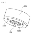
- FIG. 2 is a view of an insertion protrusion 133a of a ring gear 133 shown in FIG. 1 .
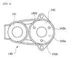
- FIG. 3 is a view of an insertion groove 142b of a housing 140 shown in FIG. 1 .
- FIGS. 1 to 3 clearly illustrate only significant parts to allow the present invention to be clearly understood in concept. As a result, various modifications in views may exist and the scope of the present invention will not be limited to particular shapes shown in the drawings.
- the parking brake actuator may include a motor 110, a power transfer unit 120, a planetary gear set 130, and the housing 140.
- the parking brake actuator may provide a parking brake with power causing a braking force.
- the torque of the motor 110 may be transferred to a spindle of the parking brake through the power transfer unit 120 and the planetary gear set 130. Also, when the spindle rotates due to the power of the motor 110, a piston is pressurized and a pad and a disc rub against each other, thereby generating the braking force.
- the motor 110 includes a shaft rotatably formed, a rotor coupled with the shaft, and a stator fixed inside the housing, in which the stator may be installed along a circumference of the rotor with a gap. Also, a coil which forms a rotational magnetic field is wound on the stator and causes an electric interaction with the rotor, thereby inducing the rotation of the rotor. When the rotor rotates, the shaft rotates and transfers power necessary for a braking force to the spindle of the parking brake.
- the power transfer unit 120 is connected to an output shaft of the motor 110 and transfers the power of the motor 110 to the planetary gear set 130.
- the power transfer unit 120 may include an idle gear 121 and a drive gear 122.
- the idle gear 121 is engaged with a pinion gear 111 connected to the shaft of the motor 110.
- the drive gear 122 rotates while being engaged with the idle gear 121.
- a linear gear 131 may be coupled below with the drive gear 122 as a double gear.
- the planetary gear set 130 shifts the power received from the power transfer unit 120 to the spindle of the parking brake.
- the planetary gear set 130 may include the linear gear 131, planetary gears 132, the ring gear 133, and a carrier 134.
- the linear gear 131 is formed to be a double gear having the same shaft with the drive gear 122 and receives the torque of the motor 110.
- the three planetary gears 132 are disposed along a circumference of the linear gear 131 to be engaged therewith simultaneously with being engaged with the ring gear 133. Also, the planetary gears 132 are supported by the carrier 134. Also, the ring gear 133 is fixed to the housing 140.
- FIG. 4 is a view of the housing 140 mounted with the ring gear 133.
- FIG. 5 is a cross-sectional view illustrating of the insertion protrusion 133a is forcibly inserted into the insertion groove 142b.
- the housing 140 may include a motor accommodating portion 141 in which the motor 110 is accommodated and a ring gear accommodating portion 142 in which the ring gear 133 is accommodated.
- the ring gear 133 is immovably fixed to the ring gear accommodating portion 142, in which the insertion protrusion 133a may be formed on a bottom of the ring gear 133 to be fixed thereto.
- the insertion groove 142b into which the insertion protrusion 133a is forcibly inserted may be formed on a bottom surface 142a of the ring gear accommodating portion 142.
- the ring gear 133 of the planetary gear set 130 is manufactured through injection molding, thereby forming a plurality of insertion protrusions 133a on the bottom of the ring gear 133.
- three insertion protrusions 133a may be formed to be arranged to be separate from one another at regular intervals along a circumferential direction on the bottom of the ring gear 133.
- Each of the insertion protrusions 133a may be formed to have a cylindrical shape.
- three insertion grooves 142b may be formed on the bottom surface 142a of the ring gear accommodating portion 142.
- the insertion groove 142b may be formed to be cylindrically concaved corresponding to the insertion protrusions 133a.
- the present invention is not limited thereto and the shape and number of the insertion protrusions 133a and the insertion grooves 142b may be variously modified.
- the housing 140 may be injection-molded while a mold is being injected with a material including a synthetic resin.
- the housing 140 may include a gear cover 143 which covers the motor accommodating portion 141 and the ring gear accommodating portion 142 and a body cover 144 which covers the gear cover 143.
- the power transfer unit 120 may be disposed between the gear cover 143 and the body cover 144.
- the idle gear 121 and the drive gear 122 may be rotatably installed.
- a configuration according to one embodiment of the present invention in which the insertion protrusion 133a is forcibly inserted into the insertion groove 142b, thereby fixing the ring gear 133 to the housing 140 may reduce the occurrence of a gap and has advantages in a tolerance design of a housing. Also, a coupling configuration between the insertion protrusion 133a and the insertion groove 142b is more easily assembled than general configurations of being inserted to slide.
- the above-described parking brake actuator according to an exemplary embodiment of the present invention is formed through injection molding in which an insertion protrusion is formed on a bottom of a ring gear, an insertion groove is formed in a bottom surface of a ring gear accommodating portion of a housing, and the insertion protrusion is forcibly inserted into the insertion groove, thereby preventing a gap between the ring gear and the housing.
- the configuration described above increases the degree of freedom in a tolerance design with respect to the ring gear accommodating portion of the housing, thereby increasing the quality of products.
- the ring gear is formed through injection molding, thereby reducing manufacturing costs.
Landscapes
- Engineering & Computer Science (AREA)
- General Engineering & Computer Science (AREA)
- Mechanical Engineering (AREA)
- Transportation (AREA)
- Retarders (AREA)
- Braking Arrangements (AREA)
- Connection Of Motors, Electrical Generators, Mechanical Devices, And The Like (AREA)
- Injection Moulding Of Plastics Or The Like (AREA)
Abstract
Description
- This application claims priority to and the benefit of Korean Patent Application No.
2014-0042474, filed APRIL 9, 2014 - The present invention relates to an electronic parking brake actuator, and more particularly, to an electronic parking brake actuator including a planetary gear set.
- An electronic parking brake (EPB) is an apparatus electronically control the driving of a parking brake. The EPB is installed on a general disc brake and performs a parking brake function. To operate the EPB, an additional actuator is necessary.
- The actuator of the EPB includes a motor installed inside a housing and a gear assembly for transferring power and reducing speed is disposed on an output shaft of the motor.
- The gear assembly may include a planetary gear set for changing speed. The planetary gear set may include a linear gear coupled with a shaft, a plurality of planetary gears engaged with a circumference of the linear gear, and a ring gear engaged with the planetary gear. Herein, the ring gear is fixed inside the housing. In general, a coupling rib is formed to protrude from an outer circumferential surface of the ring gear, a slot is formed inside the housing, and the coupling rib is inserted into the slot, thereby mounting the ring gear on the housing.
- However, considering a state of the ring gear which continuously receives torque and a tolerance with respect to the slot of the housing which is injection-molded, a gap may occur between the coupling rib and the slot in a configuration in which the coupling rib slides on the slot. As described above, when a gap occurs between the ring gear and the housing, the performance and durability of a product may have serious defects.
- The present invention is directed to provide a parking brake actuator capable of preventing a gap between a ring gear and a housing of a planetary gear set.
- The present invention is also directed to provide a parking brake actuator capable of reducing manufacturing costs.
- Aspects of the present invention are not limited thereto and additional aspects of the invention will be obvious to one of ordinary skill in the art from the following description.
- One aspect of the present invention provides a parking brake actuator including a motor, a power transfer unit connected to an output shaft of the motor, a planetary gear set including a linear gear connected to the power transfer unit, a planetary gear engaged with the linear gear, and a ring gear engaged with the planetary gear and including an insertion protrusion formed on a bottom, and a housing including a motor accommodating portion in which the motor is accommodated and a ring gear accommodating portion in which the ring gear is accommodated, in which the ring gear accommodating portion includes an insertion groove formed on a bottom surface into which the insertion protrusion is forcibly inserted.
- The ring gear may include the insertion protrusion having a cylindrical shape, and the ring gear accommodating portion may include the insertion groove having a cylindrical shape.
- A plurality of the insertion protrusions and a plurality of the insertion grooves may be disposed along a circumferential direction to be separate from one another, respectively.
- Three of the insertion protrusions and three of the insertion grooves may be disposed along the circumferential direction at regular intervals.
- The ring gear may be formed through injection molding.
- The housing may include a body including the motor accommodating portion and the ring gear accommodating portion, a gear cover which covers the motor accommodating portion and the ring gear accommodating portion, and a body cover which covers the gear cover.
- A rotating shaft of the motor and a rotating shaft of the linear gear may be disposed in parallel while being separate from each other.
- The power transfer unit may be disposed in an accommodating space formed by the gear cover and the body cover.
- The power transfer unit may include an idle gear engaged with a pinion gear coupled with the output shaft of the motor and a drive gear engaged with the idle gear simultaneously with being connected to the linear gear.
- The drive gear and the linear gear may be coupled with each other as a double gear on the same shaft.
- The above and other objects, features and advantages of the present invention will become more apparent to those of ordinary skill in the art by describing in detail exemplary embodiments thereof with reference to the attached drawings, in which:
-
FIG. 1 is a view of a parking brake actuator according to an embodiment of the present invention; -
FIG. 2 is a view of an insertion protrusion of a ring gear shown inFIG. 1 ; -
FIG. 3 is a view of an insertion groove of a housing shown inFIG. 1 ; -
FIG. 4 is a view of the housing mounted with the ring gear; and -
FIG. 5 is a cross-sectional view of the insertion protrusion is forcibly inserted into the insertion groove. - Hereinafter, exemplary embodiments of the present invention will be described in detail with reference to the attached drawings. Aspects, particular effects, and technical features will be apparent by a following detailed description related to the attached drawings and the exemplary embodiments of the present invention. Terms and words used in the description and claims will not be understood being limited to general or lexical meanings. In an aspect that the inventor may properly define the concept of the terms in order to describe embodiments in an optimal way, the terms will be understood as meanings and concepts appropriate to the technical concept of the embodiments. A detailed description on a related art which may unnecessarily make the gist of the present invention unclear will be omitted.
- Unlike before, there is provided a technical feature in which an insertion protrusion is formed on a bottom of a ring gear through injection molding and forcibly inserted into an insertion groove formed on a bottom surface of a ring gear accommodating portion of a housing, thereby preventing a gap between the ring gear and the housing.
-
FIG. 1 is a view of a parking brake actuator according to an embodiment of the present invention.FIG. 2 is a view of aninsertion protrusion 133a of aring gear 133 shown inFIG. 1 .FIG. 3 is a view of aninsertion groove 142b of ahousing 140 shown inFIG. 1 . -
FIGS. 1 to 3 clearly illustrate only significant parts to allow the present invention to be clearly understood in concept. As a result, various modifications in views may exist and the scope of the present invention will not be limited to particular shapes shown in the drawings. - Referring to
FIGS. 1 to 3 , the parking brake actuator may include amotor 110, apower transfer unit 120, a planetary gear set 130, and thehousing 140. The parking brake actuator may provide a parking brake with power causing a braking force. - In detail, the torque of the
motor 110 may be transferred to a spindle of the parking brake through thepower transfer unit 120 and the planetary gear set 130. Also, when the spindle rotates due to the power of themotor 110, a piston is pressurized and a pad and a disc rub against each other, thereby generating the braking force. - The
motor 110 includes a shaft rotatably formed, a rotor coupled with the shaft, and a stator fixed inside the housing, in which the stator may be installed along a circumference of the rotor with a gap. Also, a coil which forms a rotational magnetic field is wound on the stator and causes an electric interaction with the rotor, thereby inducing the rotation of the rotor. When the rotor rotates, the shaft rotates and transfers power necessary for a braking force to the spindle of the parking brake. - The
power transfer unit 120 is connected to an output shaft of themotor 110 and transfers the power of themotor 110 to theplanetary gear set 130. In one embodiment, thepower transfer unit 120 may include anidle gear 121 and adrive gear 122. Theidle gear 121 is engaged with apinion gear 111 connected to the shaft of themotor 110. Also, thedrive gear 122 rotates while being engaged with theidle gear 121. Alinear gear 131 may be coupled below with thedrive gear 122 as a double gear. - The planetary gear set 130 shifts the power received from the
power transfer unit 120 to the spindle of the parking brake. In one embodiment, theplanetary gear set 130 may include thelinear gear 131,planetary gears 132, thering gear 133, and acarrier 134. - The
linear gear 131 is formed to be a double gear having the same shaft with thedrive gear 122 and receives the torque of themotor 110. The threeplanetary gears 132 are disposed along a circumference of thelinear gear 131 to be engaged therewith simultaneously with being engaged with thering gear 133. Also, theplanetary gears 132 are supported by thecarrier 134. Also, thering gear 133 is fixed to thehousing 140. -
FIG. 4 is a view of thehousing 140 mounted with thering gear 133.FIG. 5 is a cross-sectional view illustrating of theinsertion protrusion 133a is forcibly inserted into theinsertion groove 142b. - The
housing 140 may include amotor accommodating portion 141 in which themotor 110 is accommodated and a ringgear accommodating portion 142 in which thering gear 133 is accommodated. As shown inFIGS. 3 and4 , thering gear 133 is immovably fixed to the ringgear accommodating portion 142, in which theinsertion protrusion 133a may be formed on a bottom of thering gear 133 to be fixed thereto. Also, theinsertion groove 142b into which theinsertion protrusion 133a is forcibly inserted may be formed on abottom surface 142a of the ringgear accommodating portion 142. - According to one embodiment of the present invention, different from general ring gears manufactured through sintering, the
ring gear 133 of the planetary gear set 130 is manufactured through injection molding, thereby forming a plurality ofinsertion protrusions 133a on the bottom of thering gear 133. - In one embodiment, three
insertion protrusions 133a may be formed to be arranged to be separate from one another at regular intervals along a circumferential direction on the bottom of thering gear 133. Each of theinsertion protrusions 133a may be formed to have a cylindrical shape. Also, corresponding to theinsertion protrusions 133a, threeinsertion grooves 142b may be formed on thebottom surface 142a of the ringgear accommodating portion 142. Theinsertion groove 142b may be formed to be cylindrically concaved corresponding to theinsertion protrusions 133a. - However, the present invention is not limited thereto and the shape and number of the
insertion protrusions 133a and theinsertion grooves 142b may be variously modified. - Meanwhile, to form the
insertion groove 142b, thehousing 140 may be injection-molded while a mold is being injected with a material including a synthetic resin. - Meanwhile, as shown in
FIG. 1 , thehousing 140 may include agear cover 143 which covers themotor accommodating portion 141 and the ringgear accommodating portion 142 and abody cover 144 which covers thegear cover 143. Thepower transfer unit 120 may be disposed between thegear cover 143 and thebody cover 144. In detail, theidle gear 121 and thedrive gear 122 may be rotatably installed. - As described above, compared with general configurations in which a coupling rib formed on an outer circumferential surface of a ring gear slides and is coupled to a housing, a configuration according to one embodiment of the present invention in which the
insertion protrusion 133a is forcibly inserted into theinsertion groove 142b, thereby fixing thering gear 133 to thehousing 140 may reduce the occurrence of a gap and has advantages in a tolerance design of a housing. Also, a coupling configuration between theinsertion protrusion 133a and theinsertion groove 142b is more easily assembled than general configurations of being inserted to slide. - As described above, the parking brake actuator according to one embodiment of the present invention has been described in detail with reference to the attached drawings.
- The above-described parking brake actuator according to an exemplary embodiment of the present invention is formed through injection molding in which an insertion protrusion is formed on a bottom of a ring gear, an insertion groove is formed in a bottom surface of a ring gear accommodating portion of a housing, and the insertion protrusion is forcibly inserted into the insertion groove, thereby preventing a gap between the ring gear and the housing.
- The configuration described above increases the degree of freedom in a tolerance design with respect to the ring gear accommodating portion of the housing, thereby increasing the quality of products.
- Also, according to one embodiment of the present invention, the ring gear is formed through injection molding, thereby reducing manufacturing costs.
- While the invention has been shown and described with reference to certain exemplary embodiments thereof, it will be understood by those skilled in the art that various changes in form and details may be made therein without departing from the spirit and scope of the invention as defined by the appended claims.
Claims (10)
- A parking brake actuator comprising:a motor;a power transfer unit connected to an output shaft of the motor;a planetary gear set comprising a linear gear connected to the power transfer unit, a planetary gear engaged with the linear gear, and a ring gear engaged with the planetary gear and comprising an insertion protrusion formed on a bottom; anda housing comprising a motor accommodating portion in which the motor is accommodated and a ring gear accommodating portion in which the ring gear is accommodated, in which the ring gear accommodating portion comprises an insertion groove formed on a bottom surface into which the insertion protrusion is forcibly inserted.
- The parking brake actuator of claim 1, wherein the ring gear comprises the insertion protrusion having a cylindrical shape, and
wherein the ring gear accommodating portion comprises the insertion groove having a cylindrical shape. - The parking brake actuator of claim 1, wherein a plurality of the insertion protrusions and a plurality of the insertion grooves are disposed along a circumferential direction to be separate from one another, respectively.
- The parking brake actuator of claim 3, wherein three of the insertion protrusions and three of the insertion grooves are disposed along the circumferential direction at regular intervals.
- The parking brake actuator of claim 1, wherein the ring gear is formed through injection molding.
- The parking brake actuator of claim 1, wherein the housing comprises:a body comprising the motor accommodating portion and the ring gear accommodating portion;a gear cover which covers the motor accommodating portion and the ring gear accommodating portion; anda body cover which covers the gear cover.
- The parking brake actuator of claim 6, wherein a rotating shaft of the motor and a rotating shaft of the linear gear are disposed in parallel while being separate from each other.
- The parking brake actuator of claim 7, wherein the power transfer unit is disposed in an accommodating space formed by the gear cover and the body cover.
- The parking brake actuator of claim 8, wherein the power transfer unit comprises:an idle gear engaged with a pinion gear coupled with the output shaft of the motor; anda drive gear engaged with the idle gear simultaneously with being connected to the linear gear.
- The parking brake actuator of claim 9, wherein the drive gear and the linear gear are coupled with each other as a double gear on the same shaft.
Applications Claiming Priority (1)
| Application Number | Priority Date | Filing Date | Title |
|---|---|---|---|
| KR1020140042474A KR20150117116A (en) | 2014-04-09 | 2014-04-09 | Electronic parking brake actuator |
Publications (2)
| Publication Number | Publication Date |
|---|---|
| EP2930075A1 true EP2930075A1 (en) | 2015-10-14 |
| EP2930075B1 EP2930075B1 (en) | 2020-09-02 |
Family
ID=53005466
Family Applications (1)
| Application Number | Title | Priority Date | Filing Date |
|---|---|---|---|
| EP15162926.8A Active EP2930075B1 (en) | 2014-04-09 | 2015-04-09 | Electronic parking brake actuator |
Country Status (4)
| Country | Link |
|---|---|
| US (1) | US10088044B2 (en) |
| EP (1) | EP2930075B1 (en) |
| KR (1) | KR20150117116A (en) |
| CN (1) | CN104976256B (en) |
Cited By (2)
| Publication number | Priority date | Publication date | Assignee | Title |
|---|---|---|---|---|
| CN105485330A (en) * | 2015-11-19 | 2016-04-13 | 浙江诸暨万宝机械有限公司 | Electronic parking brake actuator |
| US20220185256A1 (en) * | 2019-03-29 | 2022-06-16 | Mando Corporation | Actuator of electric parking brake |
Families Citing this family (20)
| Publication number | Priority date | Publication date | Assignee | Title |
|---|---|---|---|---|
| US10208858B2 (en) * | 2016-04-25 | 2019-02-19 | Continental Automotive Systems, Inc. | Internal electronic park actuator |
| US10377037B2 (en) * | 2016-09-06 | 2019-08-13 | Ubtech Robotics Corp | Speed reduction device, join servo and robot |
| DE102016221162A1 (en) * | 2016-10-27 | 2018-05-03 | Continental Teves Ag & Co. Ohg | Gear motor drive with improved noise isolation |
| CN106476782A (en) * | 2016-11-26 | 2017-03-08 | 浙江力邦合信智能制动系统股份有限公司 | A kind of motor vehicle braking system electronic parking actuator |
| CN107364436B (en) * | 2017-06-09 | 2019-05-31 | 宁波吉利汽车研究开发有限公司 | An electric booster for vehicle braking |
| KR20190133834A (en) * | 2018-05-24 | 2019-12-04 | 주식회사 만도 | Actuator for brake device |
| KR102111356B1 (en) * | 2018-07-26 | 2020-05-15 | 주식회사 만도 | Actuator for electric parking brake |
| CN111746490B (en) * | 2019-03-28 | 2023-01-06 | 启洋电机株式会社 | Electronic parking brake actuator with brush plate integrated shell |
| KR102689883B1 (en) * | 2019-04-03 | 2024-07-30 | 에이치엘만도 주식회사 | Actuator for electric parking brake |
| KR102047092B1 (en) * | 2019-04-05 | 2019-11-20 | 주식회사마르스 | Gear Reducer And Actuator For An Electric Parking Brake |
| KR102047087B1 (en) * | 2019-04-05 | 2019-11-20 | 주식회사마르스 | Actuator For An Electric Parking Brake |
| WO2020204304A1 (en) * | 2019-04-05 | 2020-10-08 | 주식회사마르스 | Electronic parking brake actuator |
| KR102691381B1 (en) * | 2019-07-16 | 2024-08-05 | 현대모비스 주식회사 | Parking brake apparatus for vehicle |
| KR102779105B1 (en) * | 2019-08-29 | 2025-03-12 | 에이치엘만도 주식회사 | Actuator for brake device |
| KR102766415B1 (en) * | 2019-11-06 | 2025-02-13 | 에이치엘만도 주식회사 | Actuator for parking brake |
| KR102766377B1 (en) | 2019-11-06 | 2025-02-13 | 에이치엘만도 주식회사 | Actuator for parking brake |
| DE102019217551A1 (en) * | 2019-11-14 | 2021-05-20 | Robert Bosch Gmbh | Electromechanically driven brake pressure generator |
| DE102020205256A1 (en) * | 2019-12-05 | 2021-06-10 | Volkswagen Aktiengesellschaft | Drive for a parking lock actuator |
| WO2021223112A1 (en) * | 2020-05-06 | 2021-11-11 | Abb Schweiz Ag | Gearbox housing and method of manufacturing the same |
| US20220362979A1 (en) * | 2021-05-11 | 2022-11-17 | Enplas Corporation | Molding systems and methods for a planetary gear carrier |
Citations (3)
| Publication number | Priority date | Publication date | Assignee | Title |
|---|---|---|---|---|
| US4617839A (en) * | 1984-07-19 | 1986-10-21 | Matex Co., Ltd. | Asymmetric planetary gear assembly |
| DE102008058098A1 (en) * | 2007-11-20 | 2009-05-28 | Gerhard Geiger Gmbh & Co. | Drive device for e.g. roller shutter, has electric motor whose speed is decreased by planetary gear having sun wheels and planetary wheels, where part of both wheels are helical toothed, and noise-insulation materials used for both wheels |
| US20100320041A1 (en) * | 2006-10-18 | 2010-12-23 | Lucas Automotive Gmbh | Single-Part Carrier for an Electric Parking Brake Actuator with Planetary Gear Set |
Family Cites Families (15)
| Publication number | Priority date | Publication date | Assignee | Title |
|---|---|---|---|---|
| US3052138A (en) * | 1960-04-11 | 1962-09-04 | Gen Motors Corp | Speed reducing gearing |
| DE102006007755B4 (en) | 2006-02-20 | 2013-10-10 | Lucas Automotive Gmbh | Low noise electric brake actuator |
| DE102009017014A1 (en) * | 2009-04-14 | 2010-10-28 | Ims Gear Gmbh | Transmission, in particular planetary gear with a flange and a ring gear |
| US8216107B2 (en) * | 2009-05-18 | 2012-07-10 | Borgwarner Inc. | Planetary ring gear lug design for NVH improvement |
| JP2011027219A (en) * | 2009-07-28 | 2011-02-10 | Hi-Lex Corporation | Actuator for electromotive parking brake and electromotive parking brake using the same |
| KR20110072877A (en) * | 2009-12-23 | 2011-06-29 | 현대모비스 주식회사 | Electronic Parking Brake Actuator Structure |
| DE102009060201A1 (en) * | 2009-12-23 | 2011-06-30 | Lucas Automotive GmbH, 56070 | Subassembly for an electromechanical brake actuator |
| US8602145B2 (en) * | 2011-08-24 | 2013-12-10 | Ta-Yu Su | Driving system for electric vehicle |
| CN103375545B (en) * | 2012-04-17 | 2017-10-13 | 德昌电机(深圳)有限公司 | Drive component, vehicle power lever gear door drive component, automatic lawn mower |
| JP6029373B2 (en) * | 2012-07-31 | 2016-11-24 | 日立オートモティブシステムズ株式会社 | Disc brake |
| JP2014070670A (en) * | 2012-09-28 | 2014-04-21 | Hitachi Automotive Systems Ltd | Disc brake |
| CN103775566B (en) * | 2012-10-26 | 2018-08-21 | 德昌电机(深圳)有限公司 | Gear drive and its assembly method |
| KR101321719B1 (en) * | 2013-04-17 | 2013-10-28 | 계양전기 주식회사 | Actuator assembly for electromechanical parking brake |
| CN104806668A (en) * | 2014-01-27 | 2015-07-29 | 德昌电机(深圳)有限公司 | Executor of electric parking brake system |
| US10316915B2 (en) * | 2014-04-01 | 2019-06-11 | Freni Brembo S.P.A. | Brake gear motor group |
-
2014
- 2014-04-09 KR KR1020140042474A patent/KR20150117116A/en not_active Ceased
-
2015
- 2015-04-09 EP EP15162926.8A patent/EP2930075B1/en active Active
- 2015-04-09 CN CN201510166009.4A patent/CN104976256B/en active Active
- 2015-04-09 US US14/682,303 patent/US10088044B2/en active Active
Patent Citations (3)
| Publication number | Priority date | Publication date | Assignee | Title |
|---|---|---|---|---|
| US4617839A (en) * | 1984-07-19 | 1986-10-21 | Matex Co., Ltd. | Asymmetric planetary gear assembly |
| US20100320041A1 (en) * | 2006-10-18 | 2010-12-23 | Lucas Automotive Gmbh | Single-Part Carrier for an Electric Parking Brake Actuator with Planetary Gear Set |
| DE102008058098A1 (en) * | 2007-11-20 | 2009-05-28 | Gerhard Geiger Gmbh & Co. | Drive device for e.g. roller shutter, has electric motor whose speed is decreased by planetary gear having sun wheels and planetary wheels, where part of both wheels are helical toothed, and noise-insulation materials used for both wheels |
Cited By (4)
| Publication number | Priority date | Publication date | Assignee | Title |
|---|---|---|---|---|
| CN105485330A (en) * | 2015-11-19 | 2016-04-13 | 浙江诸暨万宝机械有限公司 | Electronic parking brake actuator |
| CN105485330B (en) * | 2015-11-19 | 2019-07-05 | 浙江诸暨万宝机械有限公司 | A kind of electronic brake actuator |
| US20220185256A1 (en) * | 2019-03-29 | 2022-06-16 | Mando Corporation | Actuator of electric parking brake |
| US12036961B2 (en) * | 2019-03-29 | 2024-07-16 | Hl Mando Corporation | Actuator of electric parking brake |
Also Published As
| Publication number | Publication date |
|---|---|
| CN104976256A (en) | 2015-10-14 |
| CN104976256B (en) | 2019-04-30 |
| KR20150117116A (en) | 2015-10-19 |
| US20150292619A1 (en) | 2015-10-15 |
| EP2930075B1 (en) | 2020-09-02 |
| US10088044B2 (en) | 2018-10-02 |
Similar Documents
| Publication | Publication Date | Title |
|---|---|---|
| EP2930075B1 (en) | Electronic parking brake actuator | |
| EP2395631B1 (en) | Electric motor and rotor | |
| US20120164009A1 (en) | Electric pump unit | |
| JP2017207113A5 (en) | ||
| US20130064601A1 (en) | Friction bonding structure and pump device | |
| JP2011045156A (en) | Electric motor and rotor | |
| US10961775B2 (en) | Venetian and roller blind drive with damping | |
| JP2012228075A (en) | Electric motor and rotor | |
| US9343932B2 (en) | Motor | |
| KR102180737B1 (en) | Motor and power transmission apparatus including the same | |
| US9847694B2 (en) | Rotor of motor | |
| KR20180014621A (en) | Actuator | |
| CN107109757B (en) | Washing machine motor and washing machine having the same | |
| CN103670870B (en) | A kind of startup electricity generation transmission device | |
| KR102405642B1 (en) | Electric pump | |
| JP5741159B2 (en) | Electric motor and rotor | |
| KR102165612B1 (en) | Motor | |
| KR20180014620A (en) | Housing of actuator and actuator having the same | |
| CN112543846B (en) | Pump unit | |
| KR102361355B1 (en) | Shaft Rotor and Motor having the same | |
| WO2011135930A1 (en) | Cylindrical coreless motor | |
| JP2004225581A (en) | Rotor for electric water pump and method for manufacturing the same | |
| CN103085243A (en) | Molding ejection mechanism | |
| EP2744085A2 (en) | Screw motor and method of manufacturing the same | |
| CN204886499U (en) | Vehicle power consumption machine |
Legal Events
| Date | Code | Title | Description |
|---|---|---|---|
| PUAI | Public reference made under article 153(3) epc to a published international application that has entered the european phase |
Free format text: ORIGINAL CODE: 0009012 |
|
| 17P | Request for examination filed |
Effective date: 20150504 |
|
| AK | Designated contracting states |
Kind code of ref document: A1 Designated state(s): AL AT BE BG CH CY CZ DE DK EE ES FI FR GB GR HR HU IE IS IT LI LT LU LV MC MK MT NL NO PL PT RO RS SE SI SK SM TR |
|
| AX | Request for extension of the european patent |
Extension state: BA ME |
|
| RBV | Designated contracting states (corrected) |
Designated state(s): AL AT BE BG CH CY CZ DE DK EE ES FI FR GB GR HR HU IE IS IT LI LT LU LV MC MK MT NL NO PL PT RO RS SE SI SK SM TR |
|
| RAP1 | Party data changed (applicant data changed or rights of an application transferred) |
Owner name: LG INNOTEK CO., LTD. |
|
| STAA | Information on the status of an ep patent application or granted ep patent |
Free format text: STATUS: EXAMINATION IS IN PROGRESS |
|
| 17Q | First examination report despatched |
Effective date: 20191010 |
|
| GRAP | Despatch of communication of intention to grant a patent |
Free format text: ORIGINAL CODE: EPIDOSNIGR1 |
|
| STAA | Information on the status of an ep patent application or granted ep patent |
Free format text: STATUS: GRANT OF PATENT IS INTENDED |
|
| RIC1 | Information provided on ipc code assigned before grant |
Ipc: F16H 57/08 20060101ALI20200225BHEP Ipc: B60T 13/74 20060101AFI20200225BHEP Ipc: F16D 65/16 20060101ALI20200225BHEP |
|
| INTG | Intention to grant announced |
Effective date: 20200325 |
|
| GRAS | Grant fee paid |
Free format text: ORIGINAL CODE: EPIDOSNIGR3 |
|
| GRAA | (expected) grant |
Free format text: ORIGINAL CODE: 0009210 |
|
| STAA | Information on the status of an ep patent application or granted ep patent |
Free format text: STATUS: THE PATENT HAS BEEN GRANTED |
|
| AK | Designated contracting states |
Kind code of ref document: B1 Designated state(s): AL AT BE BG CH CY CZ DE DK EE ES FI FR GB GR HR HU IE IS IT LI LT LU LV MC MK MT NL NO PL PT RO RS SE SI SK SM TR |
|
| REG | Reference to a national code |
Ref country code: GB Ref legal event code: FG4D |
|
| REG | Reference to a national code |
Ref country code: AT Ref legal event code: REF Ref document number: 1308488 Country of ref document: AT Kind code of ref document: T Effective date: 20200915 Ref country code: CH Ref legal event code: EP |
|
| REG | Reference to a national code |
Ref country code: DE Ref legal event code: R096 Ref document number: 602015058244 Country of ref document: DE |
|
| REG | Reference to a national code |
Ref country code: IE Ref legal event code: FG4D |
|
| REG | Reference to a national code |
Ref country code: LT Ref legal event code: MG4D |
|
| PG25 | Lapsed in a contracting state [announced via postgrant information from national office to epo] |
Ref country code: SE Free format text: LAPSE BECAUSE OF FAILURE TO SUBMIT A TRANSLATION OF THE DESCRIPTION OR TO PAY THE FEE WITHIN THE PRESCRIBED TIME-LIMIT Effective date: 20200902 Ref country code: BG Free format text: LAPSE BECAUSE OF FAILURE TO SUBMIT A TRANSLATION OF THE DESCRIPTION OR TO PAY THE FEE WITHIN THE PRESCRIBED TIME-LIMIT Effective date: 20201202 Ref country code: HR Free format text: LAPSE BECAUSE OF FAILURE TO SUBMIT A TRANSLATION OF THE DESCRIPTION OR TO PAY THE FEE WITHIN THE PRESCRIBED TIME-LIMIT Effective date: 20200902 Ref country code: NO Free format text: LAPSE BECAUSE OF FAILURE TO SUBMIT A TRANSLATION OF THE DESCRIPTION OR TO PAY THE FEE WITHIN THE PRESCRIBED TIME-LIMIT Effective date: 20201202 Ref country code: GR Free format text: LAPSE BECAUSE OF FAILURE TO SUBMIT A TRANSLATION OF THE DESCRIPTION OR TO PAY THE FEE WITHIN THE PRESCRIBED TIME-LIMIT Effective date: 20201203 Ref country code: FI Free format text: LAPSE BECAUSE OF FAILURE TO SUBMIT A TRANSLATION OF THE DESCRIPTION OR TO PAY THE FEE WITHIN THE PRESCRIBED TIME-LIMIT Effective date: 20200902 Ref country code: LT Free format text: LAPSE BECAUSE OF FAILURE TO SUBMIT A TRANSLATION OF THE DESCRIPTION OR TO PAY THE FEE WITHIN THE PRESCRIBED TIME-LIMIT Effective date: 20200902 |
|
| REG | Reference to a national code |
Ref country code: NL Ref legal event code: MP Effective date: 20200902 |
|
| REG | Reference to a national code |
Ref country code: AT Ref legal event code: MK05 Ref document number: 1308488 Country of ref document: AT Kind code of ref document: T Effective date: 20200902 |
|
| PG25 | Lapsed in a contracting state [announced via postgrant information from national office to epo] |
Ref country code: LV Free format text: LAPSE BECAUSE OF FAILURE TO SUBMIT A TRANSLATION OF THE DESCRIPTION OR TO PAY THE FEE WITHIN THE PRESCRIBED TIME-LIMIT Effective date: 20200902 Ref country code: PL Free format text: LAPSE BECAUSE OF FAILURE TO SUBMIT A TRANSLATION OF THE DESCRIPTION OR TO PAY THE FEE WITHIN THE PRESCRIBED TIME-LIMIT Effective date: 20200902 Ref country code: RS Free format text: LAPSE BECAUSE OF FAILURE TO SUBMIT A TRANSLATION OF THE DESCRIPTION OR TO PAY THE FEE WITHIN THE PRESCRIBED TIME-LIMIT Effective date: 20200902 |
|
| PG25 | Lapsed in a contracting state [announced via postgrant information from national office to epo] |
Ref country code: CZ Free format text: LAPSE BECAUSE OF FAILURE TO SUBMIT A TRANSLATION OF THE DESCRIPTION OR TO PAY THE FEE WITHIN THE PRESCRIBED TIME-LIMIT Effective date: 20200902 Ref country code: RO Free format text: LAPSE BECAUSE OF FAILURE TO SUBMIT A TRANSLATION OF THE DESCRIPTION OR TO PAY THE FEE WITHIN THE PRESCRIBED TIME-LIMIT Effective date: 20200902 Ref country code: SM Free format text: LAPSE BECAUSE OF FAILURE TO SUBMIT A TRANSLATION OF THE DESCRIPTION OR TO PAY THE FEE WITHIN THE PRESCRIBED TIME-LIMIT Effective date: 20200902 Ref country code: EE Free format text: LAPSE BECAUSE OF FAILURE TO SUBMIT A TRANSLATION OF THE DESCRIPTION OR TO PAY THE FEE WITHIN THE PRESCRIBED TIME-LIMIT Effective date: 20200902 Ref country code: NL Free format text: LAPSE BECAUSE OF FAILURE TO SUBMIT A TRANSLATION OF THE DESCRIPTION OR TO PAY THE FEE WITHIN THE PRESCRIBED TIME-LIMIT Effective date: 20200902 Ref country code: PT Free format text: LAPSE BECAUSE OF FAILURE TO SUBMIT A TRANSLATION OF THE DESCRIPTION OR TO PAY THE FEE WITHIN THE PRESCRIBED TIME-LIMIT Effective date: 20210104 |
|
| PG25 | Lapsed in a contracting state [announced via postgrant information from national office to epo] |
Ref country code: IS Free format text: LAPSE BECAUSE OF FAILURE TO SUBMIT A TRANSLATION OF THE DESCRIPTION OR TO PAY THE FEE WITHIN THE PRESCRIBED TIME-LIMIT Effective date: 20210102 Ref country code: ES Free format text: LAPSE BECAUSE OF FAILURE TO SUBMIT A TRANSLATION OF THE DESCRIPTION OR TO PAY THE FEE WITHIN THE PRESCRIBED TIME-LIMIT Effective date: 20200902 Ref country code: AL Free format text: LAPSE BECAUSE OF FAILURE TO SUBMIT A TRANSLATION OF THE DESCRIPTION OR TO PAY THE FEE WITHIN THE PRESCRIBED TIME-LIMIT Effective date: 20200902 Ref country code: AT Free format text: LAPSE BECAUSE OF FAILURE TO SUBMIT A TRANSLATION OF THE DESCRIPTION OR TO PAY THE FEE WITHIN THE PRESCRIBED TIME-LIMIT Effective date: 20200902 |
|
| REG | Reference to a national code |
Ref country code: DE Ref legal event code: R097 Ref document number: 602015058244 Country of ref document: DE |
|
| PG25 | Lapsed in a contracting state [announced via postgrant information from national office to epo] |
Ref country code: SK Free format text: LAPSE BECAUSE OF FAILURE TO SUBMIT A TRANSLATION OF THE DESCRIPTION OR TO PAY THE FEE WITHIN THE PRESCRIBED TIME-LIMIT Effective date: 20200902 |
|
| PLBE | No opposition filed within time limit |
Free format text: ORIGINAL CODE: 0009261 |
|
| STAA | Information on the status of an ep patent application or granted ep patent |
Free format text: STATUS: NO OPPOSITION FILED WITHIN TIME LIMIT |
|
| 26N | No opposition filed |
Effective date: 20210603 |
|
| PG25 | Lapsed in a contracting state [announced via postgrant information from national office to epo] |
Ref country code: DK Free format text: LAPSE BECAUSE OF FAILURE TO SUBMIT A TRANSLATION OF THE DESCRIPTION OR TO PAY THE FEE WITHIN THE PRESCRIBED TIME-LIMIT Effective date: 20200902 Ref country code: SI Free format text: LAPSE BECAUSE OF FAILURE TO SUBMIT A TRANSLATION OF THE DESCRIPTION OR TO PAY THE FEE WITHIN THE PRESCRIBED TIME-LIMIT Effective date: 20200902 |
|
| PG25 | Lapsed in a contracting state [announced via postgrant information from national office to epo] |
Ref country code: IT Free format text: LAPSE BECAUSE OF FAILURE TO SUBMIT A TRANSLATION OF THE DESCRIPTION OR TO PAY THE FEE WITHIN THE PRESCRIBED TIME-LIMIT Effective date: 20200902 |
|
| PG25 | Lapsed in a contracting state [announced via postgrant information from national office to epo] |
Ref country code: MC Free format text: LAPSE BECAUSE OF FAILURE TO SUBMIT A TRANSLATION OF THE DESCRIPTION OR TO PAY THE FEE WITHIN THE PRESCRIBED TIME-LIMIT Effective date: 20200902 |
|
| GBPC | Gb: european patent ceased through non-payment of renewal fee |
Effective date: 20210409 |
|
| PG25 | Lapsed in a contracting state [announced via postgrant information from national office to epo] |
Ref country code: LU Free format text: LAPSE BECAUSE OF NON-PAYMENT OF DUE FEES Effective date: 20210409 |
|
| REG | Reference to a national code |
Ref country code: BE Ref legal event code: MM Effective date: 20210430 |
|
| PG25 | Lapsed in a contracting state [announced via postgrant information from national office to epo] |
Ref country code: GB Free format text: LAPSE BECAUSE OF NON-PAYMENT OF DUE FEES Effective date: 20210409 Ref country code: LI Free format text: LAPSE BECAUSE OF NON-PAYMENT OF DUE FEES Effective date: 20210430 Ref country code: CH Free format text: LAPSE BECAUSE OF NON-PAYMENT OF DUE FEES Effective date: 20210430 |
|
| PG25 | Lapsed in a contracting state [announced via postgrant information from national office to epo] |
Ref country code: IE Free format text: LAPSE BECAUSE OF NON-PAYMENT OF DUE FEES Effective date: 20210409 |
|
| PG25 | Lapsed in a contracting state [announced via postgrant information from national office to epo] |
Ref country code: IS Free format text: LAPSE BECAUSE OF FAILURE TO SUBMIT A TRANSLATION OF THE DESCRIPTION OR TO PAY THE FEE WITHIN THE PRESCRIBED TIME-LIMIT Effective date: 20210102 |
|
| PG25 | Lapsed in a contracting state [announced via postgrant information from national office to epo] |
Ref country code: BE Free format text: LAPSE BECAUSE OF NON-PAYMENT OF DUE FEES Effective date: 20210430 |
|
| PG25 | Lapsed in a contracting state [announced via postgrant information from national office to epo] |
Ref country code: HU Free format text: LAPSE BECAUSE OF FAILURE TO SUBMIT A TRANSLATION OF THE DESCRIPTION OR TO PAY THE FEE WITHIN THE PRESCRIBED TIME-LIMIT; INVALID AB INITIO Effective date: 20150409 |
|
| PG25 | Lapsed in a contracting state [announced via postgrant information from national office to epo] |
Ref country code: CY Free format text: LAPSE BECAUSE OF FAILURE TO SUBMIT A TRANSLATION OF THE DESCRIPTION OR TO PAY THE FEE WITHIN THE PRESCRIBED TIME-LIMIT Effective date: 20200902 |
|
| PG25 | Lapsed in a contracting state [announced via postgrant information from national office to epo] |
Ref country code: MK Free format text: LAPSE BECAUSE OF FAILURE TO SUBMIT A TRANSLATION OF THE DESCRIPTION OR TO PAY THE FEE WITHIN THE PRESCRIBED TIME-LIMIT Effective date: 20200902 |
|
| PG25 | Lapsed in a contracting state [announced via postgrant information from national office to epo] |
Ref country code: TR Free format text: LAPSE BECAUSE OF FAILURE TO SUBMIT A TRANSLATION OF THE DESCRIPTION OR TO PAY THE FEE WITHIN THE PRESCRIBED TIME-LIMIT Effective date: 20200902 |
|
| PG25 | Lapsed in a contracting state [announced via postgrant information from national office to epo] |
Ref country code: MT Free format text: LAPSE BECAUSE OF FAILURE TO SUBMIT A TRANSLATION OF THE DESCRIPTION OR TO PAY THE FEE WITHIN THE PRESCRIBED TIME-LIMIT Effective date: 20200902 |
|
| PGFP | Annual fee paid to national office [announced via postgrant information from national office to epo] |
Ref country code: DE Payment date: 20250320 Year of fee payment: 11 |
|
| PGFP | Annual fee paid to national office [announced via postgrant information from national office to epo] |
Ref country code: FR Payment date: 20260323 Year of fee payment: 12 |