EP2930004A1 - Vent assembly device for twin-screw extruder - Google Patents
Vent assembly device for twin-screw extruder Download PDFInfo
- Publication number
- EP2930004A1 EP2930004A1 EP14754908.3A EP14754908A EP2930004A1 EP 2930004 A1 EP2930004 A1 EP 2930004A1 EP 14754908 A EP14754908 A EP 14754908A EP 2930004 A1 EP2930004 A1 EP 2930004A1
- Authority
- EP
- European Patent Office
- Prior art keywords
- vent assembly
- vent
- units
- screw
- twin
- Prior art date
- Legal status (The legal status is an assumption and is not a legal conclusion. Google has not performed a legal analysis and makes no representation as to the accuracy of the status listed.)
- Granted
Links
Images




Classifications
-
- B—PERFORMING OPERATIONS; TRANSPORTING
- B29—WORKING OF PLASTICS; WORKING OF SUBSTANCES IN A PLASTIC STATE IN GENERAL
- B29C—SHAPING OR JOINING OF PLASTICS; SHAPING OF MATERIAL IN A PLASTIC STATE, NOT OTHERWISE PROVIDED FOR; AFTER-TREATMENT OF THE SHAPED PRODUCTS, e.g. REPAIRING
- B29C48/00—Extrusion moulding, i.e. expressing the moulding material through a die or nozzle which imparts the desired form; Apparatus therefor
- B29C48/25—Component parts, details or accessories; Auxiliary operations
- B29C48/36—Means for plasticising or homogenising the moulding material or forcing it through the nozzle or die
- B29C48/50—Details of extruders
- B29C48/76—Venting, drying means; Degassing means
- B29C48/763—Vent constructions, e.g. venting means avoiding melt escape
-
- B—PERFORMING OPERATIONS; TRANSPORTING
- B29—WORKING OF PLASTICS; WORKING OF SUBSTANCES IN A PLASTIC STATE IN GENERAL
- B29C—SHAPING OR JOINING OF PLASTICS; SHAPING OF MATERIAL IN A PLASTIC STATE, NOT OTHERWISE PROVIDED FOR; AFTER-TREATMENT OF THE SHAPED PRODUCTS, e.g. REPAIRING
- B29C48/00—Extrusion moulding, i.e. expressing the moulding material through a die or nozzle which imparts the desired form; Apparatus therefor
- B29C48/25—Component parts, details or accessories; Auxiliary operations
- B29C48/256—Exchangeable extruder parts
- B29C48/2568—Inserts
- B29C48/25684—Inserts for barrels
-
- B—PERFORMING OPERATIONS; TRANSPORTING
- B29—WORKING OF PLASTICS; WORKING OF SUBSTANCES IN A PLASTIC STATE IN GENERAL
- B29C—SHAPING OR JOINING OF PLASTICS; SHAPING OF MATERIAL IN A PLASTIC STATE, NOT OTHERWISE PROVIDED FOR; AFTER-TREATMENT OF THE SHAPED PRODUCTS, e.g. REPAIRING
- B29C48/00—Extrusion moulding, i.e. expressing the moulding material through a die or nozzle which imparts the desired form; Apparatus therefor
- B29C48/25—Component parts, details or accessories; Auxiliary operations
- B29C48/36—Means for plasticising or homogenising the moulding material or forcing it through the nozzle or die
- B29C48/395—Means for plasticising or homogenising the moulding material or forcing it through the nozzle or die using screws surrounded by a cooperating barrel, e.g. single screw extruders
- B29C48/40—Means for plasticising or homogenising the moulding material or forcing it through the nozzle or die using screws surrounded by a cooperating barrel, e.g. single screw extruders using two or more parallel screws or at least two parallel non-intermeshing screws, e.g. twin screw extruders
- B29C48/402—Means for plasticising or homogenising the moulding material or forcing it through the nozzle or die using screws surrounded by a cooperating barrel, e.g. single screw extruders using two or more parallel screws or at least two parallel non-intermeshing screws, e.g. twin screw extruders the screws having intermeshing parts
-
- B—PERFORMING OPERATIONS; TRANSPORTING
- B29—WORKING OF PLASTICS; WORKING OF SUBSTANCES IN A PLASTIC STATE IN GENERAL
- B29C—SHAPING OR JOINING OF PLASTICS; SHAPING OF MATERIAL IN A PLASTIC STATE, NOT OTHERWISE PROVIDED FOR; AFTER-TREATMENT OF THE SHAPED PRODUCTS, e.g. REPAIRING
- B29C48/00—Extrusion moulding, i.e. expressing the moulding material through a die or nozzle which imparts the desired form; Apparatus therefor
- B29C48/25—Component parts, details or accessories; Auxiliary operations
- B29C48/36—Means for plasticising or homogenising the moulding material or forcing it through the nozzle or die
- B29C48/395—Means for plasticising or homogenising the moulding material or forcing it through the nozzle or die using screws surrounded by a cooperating barrel, e.g. single screw extruders
- B29C48/40—Means for plasticising or homogenising the moulding material or forcing it through the nozzle or die using screws surrounded by a cooperating barrel, e.g. single screw extruders using two or more parallel screws or at least two parallel non-intermeshing screws, e.g. twin screw extruders
- B29C48/405—Intermeshing co-rotating screws
-
- B—PERFORMING OPERATIONS; TRANSPORTING
- B29—WORKING OF PLASTICS; WORKING OF SUBSTANCES IN A PLASTIC STATE IN GENERAL
- B29C—SHAPING OR JOINING OF PLASTICS; SHAPING OF MATERIAL IN A PLASTIC STATE, NOT OTHERWISE PROVIDED FOR; AFTER-TREATMENT OF THE SHAPED PRODUCTS, e.g. REPAIRING
- B29C48/00—Extrusion moulding, i.e. expressing the moulding material through a die or nozzle which imparts the desired form; Apparatus therefor
- B29C48/25—Component parts, details or accessories; Auxiliary operations
- B29C48/36—Means for plasticising or homogenising the moulding material or forcing it through the nozzle or die
- B29C48/50—Details of extruders
- B29C48/76—Venting, drying means; Degassing means
- B29C48/765—Venting, drying means; Degassing means in the extruder apparatus
- B29C48/766—Venting, drying means; Degassing means in the extruder apparatus in screw extruders
- B29C48/767—Venting, drying means; Degassing means in the extruder apparatus in screw extruders through a degassing opening of a barrel
Definitions
- the present invention relates to a vent assembly device for a twin-screw extruder, and more particularly to a novel improvement for making it possible to freely modify the size of a vent opening in a vent assembly, by forming the vent assembly device from a plurality of small pieces of vent assembly units.
- vent assembly devices for twin-screw extruders include, for instance, the configuration disclosed in Patent literature 1, illustrated in Fig. 13 .
- the reference symbol 7 denotes a vent assembly that is provided on a cylinder 1 of a twin-screw extruder 11.
- the whole vent assembly 7 is formed integrally so as to have a deaeration port 6.
- a first screw 2 and a second screw 3 are rotatably provided, meshing with each other, in respective screw receiving holes 4, 5 within the cylinder 1.
- An undercut 8 of the vent assembly 7 is configured so as to cover part of the first and second screws 2, 3.
- Patent literature 1 Japanese Patent Application Publication No. 2004-25669
- vent assembly structure of the twin-screw extruder must selectively utilize various types of vent assembly, such as those illustrated in Fig. 14 to Fig. 16 , depending on the viscosity, flowability and degree of adhesion of a starting material, and the volatile content generated by the starting material.
- various types of vent assembly such as those illustrated in Fig. 14 to Fig. 16 , depending on the viscosity, flowability and degree of adhesion of a starting material, and the volatile content generated by the starting material.
- substantial volatile matter content in the starting material, or substantial content of volatile matter used as a devolatilizing agent reducing the flow rate of gas at vent ports allows preventing vent rise and scattering of resin fragments (entrainment).
- an A-type having a large vent port opening of Fig. 14 is suitable herein, with high resin viscosity and no wrapping around the screws
- a C-type of Fig. 16 having a restraint on the left axis-side is suitably used for a starting material that exhibits
- vent assembly device in Fig. 14 by contrast, a vent assembly was proposed that could cope with a given specific starting material; to produce small runs of numerous article types, however, it was necessary to fabricate an optimal vent assembly device, and check the operation of the latter, depending on the viscosity, flowability, degree of adhesion and generated volatile content of the starting material whenever the starting material was changed.
- a starting material that required fine adjustments for vent rise it was necessary to fabricate a large number of vent assemblies, and to assess an optimal vent assembly for each given starting material, all of which entailed considerable expense.
- vent assemblies optimized for each starting material In the production of small runs of numerous article types as well, it was necessary to possess vent assemblies optimized for each starting material, and significant equipment costs were accordingly incurred. Preparing numerous types of vent assembly translated into necessary space for storage and storage costs, and was thus undesirable in terms of management of the twin-screw extruder.
- the present invention arrived at in order to solve such problems, resorts in particular, to a configuration wherein the size of at least a vent opening of a vent assembly can be modified freely by forming the vent assembly from a plurality of vent assembly units that are formed by dividing up the vent assembly into small pieces.
- the vent assembly device for a twin-screw extruder is a vent assembly device for a twin-screw extruder, including a vent assembly that has a vent opening and that is provided in a cylinder of a twin-screw extruder having a left axis-side screw and a right axis-side screw, wherein the size of at least the vent opening of the vent assembly can be modified freely by forming the vent assembly from a plurality of vent assembly units.
- vent assembly units corresponding to the left axis-side screw are formed of a plurality of units
- the vent assembly units corresponding to the right axis-side screw are formed of a plurality of units
- the vent assembly units have a linear shape and an L-shape as viewed in a cross-section.
- the vent assembly units corresponding to the left axis-side screw are formed of one or a plurality of units
- the vent assembly units corresponding to the right axis-side screw are formed of one or a plurality of units
- the vent assembly units have a linear shape and an L-shape as viewed in a transverse cross-section.
- Each vent assembly unit is clamped by a clamping screw configured such that a longitudinal direction thereof is disposed to be parallel to a horizontal line that joins a left axial center of the left axis-side screw and a right axial center of the right axis-side screw.
- the vent assembly units that are positioned on both outermost sides, as viewed from a cross-section of the vent assembly, have an L-shape as viewed in a cross-section.
- the vent assembly units all have an L-shaped cross-section, such that a top piece that is formed at the top of each of the vent assembly units extends in a horizontal direction, and a fixing screw is screwed in each top piece along a vertical direction.
- vent assembly device for a twin-screw extruder affords the following effects.
- a vent assembly device for a twin-screw extruder including a vent assembly that has a vent opening and that is provided in a cylinder of a twin-screw extruder having a left axis-side screw and a right axis-side screw, the size of at least the vent opening of the vent assembly can be modified freely by forming the vent assembly from a plurality of vent assembly units.
- vent shape can be easily modified on the basis of combinations of vent assembly units, even if the characteristics of the starting material varies, while no new vent assembly need be fabricated afresh. Costs can be accordingly reduced.
- vent shape can be easily modified on the basis of combinations of vent assembly units, even if the characteristics of the starting material varies, while no new vent assembly need be fabricated afresh.
- Maintenance costs can be reduced in that it becomes possible to replace just those problematic vent assembly units in case of occurrence of partial corrosion, derived from a corrosive component contained in the starting material, or partial wear of edges or the like.
- vent rise vent rise
- vent wall adhesion scattering of resin fragments (entrainment) and the like, derived from differences in, for instance, the viscosity, flowability, degree of adhesion and generated volatile content of a starting material, can be forestalled by using the vent assembly of the present invention.
- vent assembly units corresponding to the left axis-side screw are formed of a plurality of units
- the vent assembly units corresponding to the right axis-side screw are formed of a plurality of units
- the vent assembly units have a linear shape and an L-shape as viewed in a cross-section.
- the special vent shape corresponds roughly to an undercut on either one of the left axis-side screw or right axis-side screw (side of upward rotation at a meshing section). Accordingly, it suffices to prepare beforehand, or fabricate anew, a plurality of sets of vent assembly units for this screw alone.
- vent assembly units corresponding to the left axis-side screw are formed of one or a plurality of units
- the vent assembly units corresponding to the right axis-side screw are formed of one or a plurality of units
- the vent assembly units have a linear shape and an L-shape as viewed in a transverse cross-section. Vent assemblies can be fabricated easily as a result.
- Each vent assembly unit is clamped by a clamping screw configured such that a longitudinal direction thereof is disposed to be parallel to a horizontal line that joins a left axial center of the left axis-side screw and a right axial center of the right axis-side screw.
- the vent assembly can be assembled easily as a result.
- the vent assembly units that are positioned on both outermost sides, as viewed from a cross-section of the vent assembly, have an L-shape as viewed in a cross-section. As a result, the vent assembly units are fabricated very easily.
- the vent assembly units all have an L-shaped cross-section, such that a top piece that is formed at the top of each of the vent assembly units extends in a horizontal direction, and a fixing screw is screwed in each top piece along a vertical direction.
- the reference symbol 1 denotes a cylinder the overall shape thereof is that of a long tube, such that a pair of screw receiving holes 4, 5 is formed within the cylinder 1.
- the screw receiving holes 4, 5 there are respectively provided a left axis-side screw 2 and a right axis-side screw 3, so as to be rotatable along a same direction denoted by the arrows, in a state where the left axis-side screw 2 and the right axis-side screw 3 mesh with each other.
- a vent assembly 7 having a vent opening 6 is provided inside the vent receiving hole 10 that is formed within the cylinder 1.
- the vent assembly 7 is configured by a plurality of vent assembly units 7a.
- the vent assembly 7, which is illustrated as a longitudinal section, is configured by two types of vent assembly, including a vent assembly made up of a plurality of linear shapes, viewed in a longitudinal section, and a plurality of L-shapes having respective top pieces 7aA that extend in a horizontal direction and that that have a flange shape.
- the vent assembly units 7a are depicted in a state in which there is formed a vent opening 6 in the smallest state (small transversal width W) as viewed in a cross-section.
- the forms depicted in Fig. 2 to Fig. 6 below are instances where, in the configuration of Fig. 1 , the vent assembly units 7a are integrated using respective clamping screws 12 and the number of the vent assembly units 7a, corresponding to the screws 2, 3, is modified, to freely modify thereby the size (transversal width W as viewed in a cross-section) of the vent opening 6.
- vent assembly units 7a corresponding to the left axis-side screw 2
- vent assembly units 7a corresponding to the right axis-side screw 3
- a small vent opening 6 i.e. an assembly in a state where the transversal width W is small, as viewed in a cross-section.
- Each vent assembly unit 7a is clamped in a state where there is screwed a clamping screw 12 configured such that the longitudinal direction A thereof is disposed to be parallel to a horizontal line 13 that joins a left axial center P 1 and a right axial center P 2 of the respective screws 2, 3.
- the size (transversal width W) of the vent opening 6 is increased, with respect to the configuration of Fig. 2 , through a reduction in the number of the vent assembly units 7a corresponding to the right axis-side screw 3, such that the left axis-side restraint is now large, the right axis-side restraint is medium, and the size (transversal width W) of the vent opening 6 is medium.
- Fig. 4 the number of the vent assembly units 7a corresponding to the right axis-side screw 3 in Fig. 3 is reduced to only one L-shaped vent assembly unit; a state is thus brought about in which the left axis-side restraint is large, the right axis-side restraint is small, and the vent opening 6 is wide.
- the number of the vent assembly units 7a corresponding to the right axis-side screw 3 is identical to that of Fig. 2 , while the number of the vent assembly units 7a corresponding to the left axis-side screw 2 is reduced with respect to that of Fig. 2 , such that the transversal width W is greater than that of the vent opening 6 of fig. 1 , the left axis-side restraint is medium, the right axis-side restraint is large and the size of the vent opening 6 is medium.
- the configuration in Fig. 6 is the exact opposite of the configuration of Fig. 4 described above, with one vent assembly unit 7a corresponding to the left axis-side screw 2 and the number of the vent assembly units 7a corresponding to the right axis-side screw 3 set to be identical to that of the configuration of Fig. 2 ; as a result, the left axis-side restraint is small, the right axis-side restraint is large, the size of the vent opening 6 is large, and the left-right position of the vent opening 6 in Fig. 4 is the reverse of that of Fig. 6 .
- the size and position of the vent opening 6 with respect to the screws 2, 3 can be modified freely when the size and the position of the vent opening 6 are modified in a case where the characteristic of the starting material changes, and when only a vent assembly unit 7a at a problematic location is replaced, in case of occurrence of partial corrosion, derived from a corrosive component contained in the starting material, or partial wear of edges or the like, and it becomes possible to dispense with the hassle of fabricating beforehand the vent assembly 7 every time, of fabricating beforehand multiple types of the vent assembly 7, as in conventional instances.
- the vent assembly units 7a that are positioned on both outermost sides, as viewed in a cross-section have an L-shape.
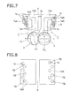
- Fig. 7 and Fig. 9 illustrate another form, different from those illustrated in Fig. 1 through Fig. 6 above.
- the vent assembly units 7a all have an L-shaped cross-section, such that at the top of the vent assembly units 7a there are formed respective top pieces 7aA that extend in the horizontal direction.
- the top pieces 7aA are fixed to each other, or to the cylinder 1, by respective fixing screws 15 that are screwed in a direction perpendicular to the horizontal line 13, i.e. in the vertical direction, via through-holes 7B that have an inner diameter larger than the outer diameter of the fixing screws 15.
- the top pieces 7aA may be staggered with respect to each other, as illustrated in Fig. 8 , or may be disposed along a straight line, as illustrated in Fig. 10 .
- Each fixing screw 15 is configured as illustrated in Fig. 9 with through-holes 7B having an inner diameter larger than the outer diameter of the fixing screws 15 being formed in the respective top pieces 7aA, such that the fixing screws 15 of the top pieces 7aA that are positioned below the uppermost top piece 7aA can be screwed-fastened and removed, at a time where respective top pieces 7aA overlap the top of the fixing screws 15.
- Fig. 11 and Fig. 12 illustrate another instance of the form illustrated in Fig. 1 through Fig. 6 above.
- a longitudinal groove 7aT and a longitudinal ridge 7aL are formed, along the vertical direction, in order to connect a respective L-shaped vent assembly unit 7a with a respective vent assembly unit 7a of linear shape.
- Each vent assembly unit 7a becomes integral with a respective longitudinal groove 7aT through fitting of the longitudinal ridge 7aL, whereupon a first and a second arc-shaped section 7aJ, 7aK become connected in a contiguous state.
- the above configuration further includes a circular eyehole 7aN formed in the top piece 7aA of each L-shaped vent assembly unit 7a, so that the fitting state of the longitudinal ridge 7aL with the longitudinal groove 7aT can be checked via the eyehole 7aN.
- Fig. 12 illustrates another form of Fig. 11 .
- all the vent assembly units 7a have a linear shape, and a plurality of transversal ridges 7aY is provided in one vent assembly unit 7a while transversal grooves 7aM into which the transversal ridges 7aY fit are formed in the other vent assembly unit 7a.
- a shape in which the first and the second arc-shaped sections 7aJ and 7aK are contiguous is thus achieved by combining the vent assembly units 7a.
- Fig. 11 and Fig. 12 illustrate a pair of vent assembly units 7a, but other combinations of one or more pairs can also be resorted to, as needed.
- the vent assembly device for a twin-screw extruder allows freely modifying the size of a vent opening of a vent assembly. This makes the vent assembly device for a twin-screw extruder suitable for, for instance, testing of novel extrusion processes.
Landscapes
- Engineering & Computer Science (AREA)
- Mechanical Engineering (AREA)
- Extrusion Moulding Of Plastics Or The Like (AREA)
Abstract
Description
- The present invention relates to a vent assembly device for a twin-screw extruder, and more particularly to a novel improvement for making it possible to freely modify the size of a vent opening in a vent assembly, by forming the vent assembly device from a plurality of small pieces of vent assembly units.
- Conventional examples of various vent assembly devices for twin-screw extruders include, for instance, the configuration disclosed in
Patent literature 1, illustrated inFig. 13 . - In
Fig. 13 , thereference symbol 7 denotes a vent assembly that is provided on acylinder 1 of a twin-screw extruder 11. Thewhole vent assembly 7 is formed integrally so as to have adeaeration port 6. - A
first screw 2 and asecond screw 3 are rotatably provided, meshing with each other, in respectivescrew receiving holes cylinder 1. Anundercut 8 of thevent assembly 7 is configured so as to cover part of the first andsecond screws - Patent literature 1: Japanese Patent Application Publication No.
2004-25669 - Due to the above configuration, conventional vent assembly devices for twin-screw extruders exhibited the following problems.
- Specifically, the vent assembly structure of the twin-screw extruder must selectively utilize various types of vent assembly, such as those illustrated in
Fig. 14 to Fig. 16 , depending on the viscosity, flowability and degree of adhesion of a starting material, and the volatile content generated by the starting material. In a case, for instance, of substantial volatile matter content in the starting material, or substantial content of volatile matter used as a devolatilizing agent, reducing the flow rate of gas at vent ports allows preventing vent rise and scattering of resin fragments (entrainment). Accordingly, an A-type having a large vent port opening ofFig. 14 is suitable herein, with high resin viscosity and no wrapping around the screws, while a C-type ofFig. 16 , having a restraint on the left axis-side is suitably used for a starting material that exhibits resin jumping as a result of the rotation of the screws. - In the vent assembly device in
Fig. 14 , by contrast, a vent assembly was proposed that could cope with a given specific starting material; to produce small runs of numerous article types, however, it was necessary to fabricate an optimal vent assembly device, and check the operation of the latter, depending on the viscosity, flowability, degree of adhesion and generated volatile content of the starting material whenever the starting material was changed. When using a starting material that required fine adjustments for vent rise, it was necessary to fabricate a large number of vent assemblies, and to assess an optimal vent assembly for each given starting material, all of which entailed considerable expense. In the production of small runs of numerous article types as well, it was necessary to possess vent assemblies optimized for each starting material, and significant equipment costs were accordingly incurred. Preparing numerous types of vent assembly translated into necessary space for storage and storage costs, and was thus undesirable in terms of management of the twin-screw extruder. - The present invention, arrived at in order to solve such problems, resorts in particular, to a configuration wherein the size of at least a vent opening of a vent assembly can be modified freely by forming the vent assembly from a plurality of vent assembly units that are formed by dividing up the vent assembly into small pieces.
- The vent assembly device for a twin-screw extruder according to the present invention is a vent assembly device for a twin-screw extruder, including a vent assembly that has a vent opening and that is provided in a cylinder of a twin-screw extruder having a left axis-side screw and a right axis-side screw, wherein the size of at least the vent opening of the vent assembly can be modified freely by forming the vent assembly from a plurality of vent assembly units. Further, the vent assembly units corresponding to the left axis-side screw are formed of a plurality of units, the vent assembly units corresponding to the right axis-side screw are formed of a plurality of units, and the vent assembly units have a linear shape and an L-shape as viewed in a cross-section. Further, the vent assembly units corresponding to the left axis-side screw are formed of one or a plurality of units, the vent assembly units corresponding to the right axis-side screw are formed of one or a plurality of units, and the vent assembly units have a linear shape and an L-shape as viewed in a transverse cross-section. Each vent assembly unit is clamped by a clamping screw configured such that a longitudinal direction thereof is disposed to be parallel to a horizontal line that joins a left axial center of the left axis-side screw and a right axial center of the right axis-side screw. From among the vent assembly units, the vent assembly units that are positioned on both outermost sides, as viewed from a cross-section of the vent assembly, have an L-shape as viewed in a cross-section. The vent assembly units all have an L-shaped cross-section, such that a top piece that is formed at the top of each of the vent assembly units extends in a horizontal direction, and a fixing screw is screwed in each top piece along a vertical direction.
- By virtue of the above features, the vent assembly device for a twin-screw extruder according to the present invention affords the following effects.
- In a vent assembly device for a twin-screw extruder, including a vent assembly that has a vent opening and that is provided in a cylinder of a twin-screw extruder having a left axis-side screw and a right axis-side screw, the size of at least the vent opening of the vent assembly can be modified freely by forming the vent assembly from a plurality of vent assembly units. In consequence, vent shape can be easily modified on the basis of combinations of vent assembly units, even if the characteristics of the starting material varies, while no new vent assembly need be fabricated afresh. Costs can be accordingly reduced.
- Further, times can be shortened since the vent shape can be easily modified on the basis of combinations of vent assembly units, even if the characteristics of the starting material varies, while no new vent assembly need be fabricated afresh.
- Maintenance costs can be reduced in that it becomes possible to replace just those problematic vent assembly units in case of occurrence of partial corrosion, derived from a corrosive component contained in the starting material, or partial wear of edges or the like.
- Therefore, the occurrence of problems such as vent rise, vent wall adhesion, scattering of resin fragments (entrainment) and the like, derived from differences in, for instance, the viscosity, flowability, degree of adhesion and generated volatile content of a starting material, can be forestalled by using the vent assembly of the present invention.
- Further, the vent assembly units corresponding to the left axis-side screw are formed of a plurality of units, the vent assembly units corresponding to the right axis-side screw are formed of a plurality of units, and the vent assembly units have a linear shape and an L-shape as viewed in a cross-section. As a result, the configuration of the vent assembly units is simplified, and handling and management are made easier.
- In the case of an extruder of co-rotating twin screws where a special vent shape is necessary for coping with a specific starting material, the special vent shape corresponds roughly to an undercut on either one of the left axis-side screw or right axis-side screw (side of upward rotation at a meshing section). Accordingly, it suffices to prepare beforehand, or fabricate anew, a plurality of sets of vent assembly units for this screw alone.
- Further, the vent assembly units corresponding to the left axis-side screw are formed of one or a plurality of units, the vent assembly units corresponding to the right axis-side screw are formed of one or a plurality of units, and the vent assembly units have a linear shape and an L-shape as viewed in a transverse cross-section. Vent assemblies can be fabricated easily as a result.
- Each vent assembly unit is clamped by a clamping screw configured such that a longitudinal direction thereof is disposed to be parallel to a horizontal line that joins a left axial center of the left axis-side screw and a right axial center of the right axis-side screw. The vent assembly can be assembled easily as a result.
- From among the vent assembly units, the vent assembly units that are positioned on both outermost sides, as viewed from a cross-section of the vent assembly, have an L-shape as viewed in a cross-section. As a result, the vent assembly units are fabricated very easily.
- The vent assembly units all have an L-shaped cross-section, such that a top piece that is formed at the top of each of the vent assembly units extends in a horizontal direction, and a fixing screw is screwed in each top piece along a vertical direction. As a result, it becomes possible to attach/detach just the vent assembly units the number of which is to be increased/reduced, and to modify vent shape efficiently, while those vent assembly units that do not pertain to an intended shape modification are kept attached to the twin-screw extruder.
-
-
Fig. 1 is a cross-sectional diagram illustrating a vent assembly device for a twin-screw extruder according to the present invention; -
Fig. 2 is a cross-sectional diagram illustrating a clamped state ofFig. 1 ; -
Fig. 3 is a cross-sectional diagram illustrating another form ofFig. 2 ; -
Fig. 4 is a cross-sectional diagram illustrating another form ofFig. 2 ; -
Fig. 5 is a cross-sectional diagram illustrating another form ofFig. 1 ; -
Fig. 6 is a cross-sectional diagram illustrating another form ofFig. 1 ; -
Fig. 7 is a cross-sectional diagram illustrating another form ofFig. 1 ; -
Fig. 8 is a plan-view diagram ofFig. 7 ; -
Fig. 9 is a cross-sectional diagram illustrating another form ofFig. 7 ; -
Fig. 10 is a plan-view diagram ofFig. 9 ; -
Fig. 11 is an exploded perspective-view diagram illustrating another form ofFig. 1 ; -
Fig. 12 is an exploded perspective-view diagram illustrating another form ofFig. 11 ; -
Fig. 13 is a cross-sectional diagram illustrating a vent assembly device of a conventional twin-screw extruder; -
Fig. 14 is a cross-sectional diagram illustrating a conventionally used vent assembly; -
Fig. 15 is a cross-sectional diagram illustrating another form ofFig. 12 ; and -
Fig. 16 is a cross-sectional diagram illustrating another form ofFig. 12 . - It is an object of the present invention to provide a vent assembly device for a twin-screw extruder such that the size of a vent opening of a vent assembly can be freely modified by forming a vent assembly from a plurality of vent assembly units.
- Preferred embodiments of the vent assembly device for a twin-screw extruder according to the present invention will be explained next with reference to accompanying drawings.
- Portions identical or similar to those of the conventional example will be explained using identical reference symbols.
- In
Fig. 1 , thereference symbol 1 denotes a cylinder the overall shape thereof is that of a long tube, such that a pair ofscrew receiving holes cylinder 1. In thescrew receiving holes side screw 2 and a right axis-side screw 3, so as to be rotatable along a same direction denoted by the arrows, in a state where the left axis-side screw 2 and the right axis-side screw 3 mesh with each other. - A
vent assembly 7 having avent opening 6 is provided inside thevent receiving hole 10 that is formed within thecylinder 1. Thevent assembly 7 is configured by a plurality ofvent assembly units 7a. - The
vent assembly 7, which is illustrated as a longitudinal section, is configured by two types of vent assembly, including a vent assembly made up of a plurality of linear shapes, viewed in a longitudinal section, and a plurality of L-shapes having respective top pieces 7aA that extend in a horizontal direction and that that have a flange shape. - In the case of
Fig. 1 , thevent assembly units 7a are depicted in a state in which there is formed avent opening 6 in the smallest state (small transversal width W) as viewed in a cross-section. However, the forms depicted inFig. 2 to Fig. 6 below are instances where, in the configuration ofFig. 1 , thevent assembly units 7a are integrated using respective clamping screws 12 and the number of thevent assembly units 7a, corresponding to thescrews vent opening 6. - In the form of
Fig. 2 there are sixvent assembly units 7a corresponding to the left axis-side screw 2, and sixvent assembly units 7a corresponding to the right axis-side screw 3, in a configuration with identical number of units, with a large left axis-side restraint, a large right axis-side restraint, and asmall vent opening 6, i.e. an assembly in a state where the transversal width W is small, as viewed in a cross-section. - Each
vent assembly unit 7a is clamped in a state where there is screwed a clampingscrew 12 configured such that the longitudinal direction A thereof is disposed to be parallel to ahorizontal line 13 that joins a left axial center P1 and a right axial center P2 of therespective screws - In the configuration of
Fig. 3 , the size (transversal width W) of thevent opening 6 is increased, with respect to the configuration ofFig. 2 , through a reduction in the number of thevent assembly units 7a corresponding to the right axis-side screw 3, such that the left axis-side restraint is now large, the right axis-side restraint is medium, and the size (transversal width W) of thevent opening 6 is medium. - In
Fig. 4 , the number of thevent assembly units 7a corresponding to the right axis-side screw 3 inFig. 3 is reduced to only one L-shaped vent assembly unit; a state is thus brought about in which the left axis-side restraint is large, the right axis-side restraint is small, and thevent opening 6 is wide. - In the configuration of
Fig. 5 , the number of thevent assembly units 7a corresponding to the right axis-side screw 3 is identical to that ofFig. 2 , while the number of thevent assembly units 7a corresponding to the left axis-side screw 2 is reduced with respect to that ofFig. 2 , such that the transversal width W is greater than that of thevent opening 6 offig. 1 , the left axis-side restraint is medium, the right axis-side restraint is large and the size of thevent opening 6 is medium. - The configuration in
Fig. 6 is the exact opposite of the configuration ofFig. 4 described above, with onevent assembly unit 7a corresponding to the left axis-side screw 2 and the number of thevent assembly units 7a corresponding to the right axis-side screw 3 set to be identical to that of the configuration ofFig. 2 ; as a result, the left axis-side restraint is small, the right axis-side restraint is large, the size of thevent opening 6 is large, and the left-right position of thevent opening 6 inFig. 4 is the reverse of that ofFig. 6 . - Therefore, as illustrated in the examples of
Fig. 2 through Fig. 6 described above, the size and position of thevent opening 6 with respect to thescrews vent opening 6 are modified in a case where the characteristic of the starting material changes, and when only avent assembly unit 7a at a problematic location is replaced, in case of occurrence of partial corrosion, derived from a corrosive component contained in the starting material, or partial wear of edges or the like, and it becomes possible to dispense with the hassle of fabricating beforehand thevent assembly 7 every time, of fabricating beforehand multiple types of thevent assembly 7, as in conventional instances. In thevent assembly 7 inFig. 1 to Fig. 6 described above, thevent assembly units 7a that are positioned on both outermost sides, as viewed in a cross-section, have an L-shape. -
Fig. 7 andFig. 9 illustrate another form, different from those illustrated inFig. 1 through Fig. 6 above. Thevent assembly units 7a all have an L-shaped cross-section, such that at the top of thevent assembly units 7a there are formed respective top pieces 7aA that extend in the horizontal direction. The top pieces 7aA are fixed to each other, or to thecylinder 1, by respective fixing screws 15 that are screwed in a direction perpendicular to thehorizontal line 13, i.e. in the vertical direction, via through-holes 7B that have an inner diameter larger than the outer diameter of the fixing screws 15. - When the mutual arrangement of the fixing screws 15 is viewed from above the
vent assembly 7, the top pieces 7aA may be staggered with respect to each other, as illustrated inFig. 8 , or may be disposed along a straight line, as illustrated inFig. 10 . - Each fixing
screw 15 is configured as illustrated inFig. 9 with through-holes 7B having an inner diameter larger than the outer diameter of the fixing screws 15 being formed in the respective top pieces 7aA, such that the fixing screws 15 of the top pieces 7aA that are positioned below the uppermost top piece 7aA can be screwed-fastened and removed, at a time where respective top pieces 7aA overlap the top of the fixing screws 15. - In the case of the form illustrated in
Fig. 7 andFig. 9 , it becomes therefore possible to insert and remove only those vent assembly units of interest, without removal of the entire vent assembly, when increasing and reducing the number ofvent assembly units 7a as needed. Accordingly, the size of thevent opening 6 and the position thereof corresponding to thescrews Fig. 2 above to that ofFig. 6 . -
Fig. 11 and Fig. 12 illustrate another instance of the form illustrated inFig. 1 through Fig. 6 above. InFig. 11 , a longitudinal groove 7aT and a longitudinal ridge 7aL are formed, along the vertical direction, in order to connect a respective L-shapedvent assembly unit 7a with a respectivevent assembly unit 7a of linear shape. - Each
vent assembly unit 7a becomes integral with a respective longitudinal groove 7aT through fitting of the longitudinal ridge 7aL, whereupon a first and a second arc-shaped section 7aJ, 7aK become connected in a contiguous state. - The above configuration further includes a circular eyehole 7aN formed in the top piece 7aA of each L-shaped
vent assembly unit 7a, so that the fitting state of the longitudinal ridge 7aL with the longitudinal groove 7aT can be checked via the eyehole 7aN. -
Fig. 12 illustrates another form ofFig. 11 . In this form, all thevent assembly units 7a have a linear shape, and a plurality of transversal ridges 7aY is provided in onevent assembly unit 7a while transversal grooves 7aM into which the transversal ridges 7aY fit are formed in the othervent assembly unit 7a. A shape in which the first and the second arc-shaped sections 7aJ and 7aK are contiguous is thus achieved by combining thevent assembly units 7a. -
Fig. 11 and Fig. 12 illustrate a pair ofvent assembly units 7a, but other combinations of one or more pairs can also be resorted to, as needed. - Through formation of a vent assembly in the form of a plurality of vent assembly units, the vent assembly device for a twin-screw extruder according to the present invention allows freely modifying the size of a vent opening of a vent assembly. This makes the vent assembly device for a twin-screw extruder suitable for, for instance, testing of novel extrusion processes.
-
- 1
- cylinder
- 2
- left axis-side screw
- 3
- right axis-side screw
- 4, 5
- screw receiving hole
- 6
- vent opening
- 7
- vent assembly
- 7a
- vent assembly units
- 7B
- through-hole
- 7aA
- top piece
- 10
- vent receiving hole
- 11
- twin-screw extruder
- 12
- clamping screw
- 13
- horizontal line
- 15
- fixing screw
- P1
- left axial center
- P2
- right axial center
- A
- longitudinal direction
- 7aJ
- first arc-shaped section
- 7aK
- second arc-shaped section
- 7aL
- longitudinal ridge
- 7aT
- longitudinal groove
- 7aY
- transversal ridges
- 7aM
- transversal groove
Claims (6)
- A vent assembly device for a twin-screw extruder, comprising a vent assembly (7) that has a vent opening (6) and that is provided in a cylinder (1) of a twin-screw extruder (11) having a left axis-side screw (2) and a right axis-side screw (3),
wherein the size of at least the vent opening (6) of the vent assembly (7) can be freely modified by forming the vent assembly (7) from a plurality of vent assembly units (7a). - The vent assembly device for a twin-screw extruder according to claim 1, wherein the vent assembly units (7a) corresponding to the left axis-side screw (2) are formed of a plurality of units, the vent assembly units (7a) corresponding to the right axis-side screw (3) are formed of a plurality of units, and the vent assembly units (7a) have a linear shape and an L-shape as viewed in a cross-section.
- The vent assembly device for a twin-screw extruder according to claim 1, wherein the vent assembly units (7a) corresponding to the left axis-side screw (2) are formed of one or a plurality of units, the vent assembly units (7a) corresponding to the right axis-side screw (3) are formed of one or a plurality of units, and the vent assembly units (7a) have a linear shape and an L-shape as viewed in a cross-section.
- The vent assembly device for a twin-screw extruder according to any one of claims 1 to 3, wherein each of the vent assembly units (7a) is clamped by a clamping screw (12) configured such that a longitudinal direction (A) thereof is disposed to be parallel to a horizontal line (13) that joins a left axial center (P1) of the left axis-side screw (2) and a right axial center (P2) of the right axis-side screw (3).
- The vent assembly device for a twin-screw extruder according to any one of claims 1 to 4, wherein from among the vent assembly units (7a), the vent assembly units (7a) that are positioned on both outermost sides, as viewed from a cross-section of the vent assembly (7), have an L-shape as viewed in a cross-section.
- The vent assembly device for a twin-screw extruder according to claim 1, wherein the vent assembly units (7a) all have an L-shaped cross-section, such that a top piece (7aA) that is formed at the top of each of the vent assembly units (7a) extends in a horizontal direction, and a fixing screw (15) is screwed in each top piece (7aA) along a vertical direction.
Applications Claiming Priority (2)
| Application Number | Priority Date | Filing Date | Title |
|---|---|---|---|
| JP2013031974A JP5623568B2 (en) | 2013-02-21 | 2013-02-21 | Bent hardware for twin screw extruder |
| PCT/JP2014/053256 WO2014129367A1 (en) | 2013-02-21 | 2014-02-13 | Vent assembly device for twin-screw extruder |
Publications (3)
| Publication Number | Publication Date |
|---|---|
| EP2930004A1 true EP2930004A1 (en) | 2015-10-14 |
| EP2930004A4 EP2930004A4 (en) | 2016-08-31 |
| EP2930004B1 EP2930004B1 (en) | 2018-05-02 |
Family
ID=51391162
Family Applications (1)
| Application Number | Title | Priority Date | Filing Date |
|---|---|---|---|
| EP14754908.3A Active EP2930004B1 (en) | 2013-02-21 | 2014-02-13 | Vent assembly device for twin-screw extruder |
Country Status (5)
| Country | Link |
|---|---|
| US (1) | US9731448B2 (en) |
| EP (1) | EP2930004B1 (en) |
| JP (1) | JP5623568B2 (en) |
| CN (1) | CN104995009B (en) |
| WO (1) | WO2014129367A1 (en) |
Cited By (1)
| Publication number | Priority date | Publication date | Assignee | Title |
|---|---|---|---|---|
| WO2025166393A1 (en) * | 2024-02-09 | 2025-08-14 | 4Next Generation Gmbh | Device for processing plastics material |
Families Citing this family (2)
| Publication number | Priority date | Publication date | Assignee | Title |
|---|---|---|---|---|
| JP6757507B2 (en) * | 2016-01-22 | 2020-09-23 | 東レ株式会社 | Method for manufacturing thermoplastic resin composition |
| JP7307635B2 (en) * | 2019-09-03 | 2023-07-12 | 株式会社日本製鋼所 | Twin-screw kneading extruder and vent adapter |
Family Cites Families (12)
| Publication number | Priority date | Publication date | Assignee | Title |
|---|---|---|---|---|
| US2078565A (en) * | 1933-10-30 | 1937-04-27 | Durst Emanuel | Vacuum press and the like |
| US3917507A (en) * | 1971-02-22 | 1975-11-04 | Welding Engineers | Countercurrent combined liquid and vapor stripping in screw devolatilizer |
| JP2839353B2 (en) * | 1990-10-22 | 1998-12-16 | 株式会社神戸製鋼所 | Vent device for twin-screw kneader |
| DE4228468A1 (en) * | 1992-08-27 | 1994-03-03 | Werner & Pfleiderer | Degassing device for a twin-screw machine for processing plastics |
| DE19630383C1 (en) * | 1996-07-29 | 1997-09-18 | Christ Hubert Dr | Degassing arrangement for plastics screw processing machine |
| JP2001138381A (en) * | 1999-11-12 | 2001-05-22 | Japan Steel Works Ltd:The | Side vent device |
| JP3712185B2 (en) * | 2001-01-17 | 2005-11-02 | 株式会社日本製鋼所 | Fine powder material supply equipment |
| JP2004025669A (en) * | 2002-06-26 | 2004-01-29 | Japan Steel Works Ltd:The | Extruder vent hardware and extruder |
| CN2567025Y (en) * | 2002-11-23 | 2003-08-20 | 汕头市奇佳机械厂有限公司 | Venting device of sheet extruder |
| ATE541691T1 (en) | 2009-02-11 | 2012-02-15 | Coperion Gmbh | SCREW MACHINE |
| JP5467796B2 (en) | 2009-04-24 | 2014-04-09 | 株式会社三和商会 | Extruder vent apparatus and kneading method using an extruder |
| CN202129974U (en) * | 2011-07-25 | 2012-02-01 | 浙江百纳橡塑设备有限公司 | Exhausting device of rubber extruding machine |
-
2013
- 2013-02-21 JP JP2013031974A patent/JP5623568B2/en active Active
-
2014
- 2014-02-13 CN CN201480009359.3A patent/CN104995009B/en active Active
- 2014-02-13 EP EP14754908.3A patent/EP2930004B1/en active Active
- 2014-02-13 WO PCT/JP2014/053256 patent/WO2014129367A1/en not_active Ceased
- 2014-02-13 US US14/651,446 patent/US9731448B2/en active Active
Cited By (1)
| Publication number | Priority date | Publication date | Assignee | Title |
|---|---|---|---|---|
| WO2025166393A1 (en) * | 2024-02-09 | 2025-08-14 | 4Next Generation Gmbh | Device for processing plastics material |
Also Published As
| Publication number | Publication date |
|---|---|
| EP2930004B1 (en) | 2018-05-02 |
| US9731448B2 (en) | 2017-08-15 |
| JP2014162013A (en) | 2014-09-08 |
| US20150314512A1 (en) | 2015-11-05 |
| CN104995009A (en) | 2015-10-21 |
| CN104995009B (en) | 2017-05-24 |
| WO2014129367A1 (en) | 2014-08-28 |
| EP2930004A4 (en) | 2016-08-31 |
| JP5623568B2 (en) | 2014-11-12 |
Similar Documents
| Publication | Publication Date | Title |
|---|---|---|
| US10207423B2 (en) | Extruder mixing element for a co-rotating twin screw extruder | |
| US7981340B2 (en) | Method of degassing a flowable mass in a ring extruder | |
| EP2930004B1 (en) | Vent assembly device for twin-screw extruder | |
| JP2011524284A5 (en) | ||
| DE102009019226A1 (en) | Lighting element arrangement for use in outdoor areas, has turbojets provided for conveying cooling medium through cooling duct that is arranged in LED unit, and venture tube formed in solid cooling body that is made of metal | |
| CN107532698A (en) | ball screw | |
| US9855697B2 (en) | Wearing body for receiving a twin screw for extruding meltable material | |
| CA2949392C (en) | A mould tool for injection moulding | |
| WO2018079241A1 (en) | Extrusion head and extrusion device | |
| US20250196077A1 (en) | Screw elements with improved mixing effect and pressure build-up | |
| CN105864289B (en) | A kind of assembly type modularity guide rail | |
| EP2821196A1 (en) | Screw pair and co-rotating intermeshing twin-screw extruder provided with screw pair | |
| JP6759707B2 (en) | Screws, extruders and mixing devices | |
| KR0125105B1 (en) | Cylinder of the extruding molding machine | |
| CN221985777U (en) | Twin-screw extruder barrel with assembled bimetallic bushing | |
| JP6772546B2 (en) | Screws, extruders and collars | |
| CN211279902U (en) | Split type single screw extruder | |
| CN208664339U (en) | A kind of fire retardation PC/ABS alloy material extrusion structure | |
| JP2002283434A (en) | Kneading ring and screw-type kneading extruder | |
| ITUB20154130A1 (en) | JOINT FOR THE TRANSMISSION OF THE COUPLE AND GROUP OF TRANSMISSION OF THE TORQUE INCLUDING SUCH JOINT | |
| CN202651622U (en) | Switch cabinet section material | |
| JP2007118519A (en) | Breaker plate and extrusion molding machine using it | |
| CN113290821A (en) | Double-screw extruder head | |
| UA12124U (en) | Single-worm extruder | |
| UA15248U (en) | Housing of two-worm extruder |
Legal Events
| Date | Code | Title | Description |
|---|---|---|---|
| PUAI | Public reference made under article 153(3) epc to a published international application that has entered the european phase |
Free format text: ORIGINAL CODE: 0009012 |
|
| 17P | Request for examination filed |
Effective date: 20150617 |
|
| AK | Designated contracting states |
Kind code of ref document: A1 Designated state(s): AL AT BE BG CH CY CZ DE DK EE ES FI FR GB GR HR HU IE IS IT LI LT LU LV MC MK MT NL NO PL PT RO RS SE SI SK SM TR |
|
| AX | Request for extension of the european patent |
Extension state: BA ME |
|
| DAX | Request for extension of the european patent (deleted) | ||
| RA4 | Supplementary search report drawn up and despatched (corrected) |
Effective date: 20160728 |
|
| RIC1 | Information provided on ipc code assigned before grant |
Ipc: B29C 47/08 20060101ALI20160722BHEP Ipc: B29C 47/40 20060101ALI20160722BHEP Ipc: B29C 47/76 20060101AFI20160722BHEP |
|
| STAA | Information on the status of an ep patent application or granted ep patent |
Free format text: STATUS: EXAMINATION IS IN PROGRESS |
|
| 17Q | First examination report despatched |
Effective date: 20170608 |
|
| GRAP | Despatch of communication of intention to grant a patent |
Free format text: ORIGINAL CODE: EPIDOSNIGR1 |
|
| STAA | Information on the status of an ep patent application or granted ep patent |
Free format text: STATUS: GRANT OF PATENT IS INTENDED |
|
| INTG | Intention to grant announced |
Effective date: 20171208 |
|
| GRAS | Grant fee paid |
Free format text: ORIGINAL CODE: EPIDOSNIGR3 |
|
| GRAA | (expected) grant |
Free format text: ORIGINAL CODE: 0009210 |
|
| STAA | Information on the status of an ep patent application or granted ep patent |
Free format text: STATUS: THE PATENT HAS BEEN GRANTED |
|
| AK | Designated contracting states |
Kind code of ref document: B1 Designated state(s): AL AT BE BG CH CY CZ DE DK EE ES FI FR GB GR HR HU IE IS IT LI LT LU LV MC MK MT NL NO PL PT RO RS SE SI SK SM TR |
|
| REG | Reference to a national code |
Ref country code: GB Ref legal event code: FG4D |
|
| REG | Reference to a national code |
Ref country code: CH Ref legal event code: EP Ref country code: AT Ref legal event code: REF Ref document number: 994725 Country of ref document: AT Kind code of ref document: T Effective date: 20180515 |
|
| REG | Reference to a national code |
Ref country code: DE Ref legal event code: R096 Ref document number: 602014024886 Country of ref document: DE |
|
| REG | Reference to a national code |
Ref country code: IE Ref legal event code: FG4D |
|
| REG | Reference to a national code |
Ref country code: NL Ref legal event code: MP Effective date: 20180502 |
|
| REG | Reference to a national code |
Ref country code: LT Ref legal event code: MG4D |
|
| PG25 | Lapsed in a contracting state [announced via postgrant information from national office to epo] |
Ref country code: SE Free format text: LAPSE BECAUSE OF FAILURE TO SUBMIT A TRANSLATION OF THE DESCRIPTION OR TO PAY THE FEE WITHIN THE PRESCRIBED TIME-LIMIT Effective date: 20180502 Ref country code: ES Free format text: LAPSE BECAUSE OF FAILURE TO SUBMIT A TRANSLATION OF THE DESCRIPTION OR TO PAY THE FEE WITHIN THE PRESCRIBED TIME-LIMIT Effective date: 20180502 Ref country code: LT Free format text: LAPSE BECAUSE OF FAILURE TO SUBMIT A TRANSLATION OF THE DESCRIPTION OR TO PAY THE FEE WITHIN THE PRESCRIBED TIME-LIMIT Effective date: 20180502 Ref country code: BG Free format text: LAPSE BECAUSE OF FAILURE TO SUBMIT A TRANSLATION OF THE DESCRIPTION OR TO PAY THE FEE WITHIN THE PRESCRIBED TIME-LIMIT Effective date: 20180802 Ref country code: FI Free format text: LAPSE BECAUSE OF FAILURE TO SUBMIT A TRANSLATION OF THE DESCRIPTION OR TO PAY THE FEE WITHIN THE PRESCRIBED TIME-LIMIT Effective date: 20180502 Ref country code: NO Free format text: LAPSE BECAUSE OF FAILURE TO SUBMIT A TRANSLATION OF THE DESCRIPTION OR TO PAY THE FEE WITHIN THE PRESCRIBED TIME-LIMIT Effective date: 20180802 |
|
| REG | Reference to a national code |
Ref country code: DE Ref legal event code: R079 Ref document number: 602014024886 Country of ref document: DE Free format text: PREVIOUS MAIN CLASS: B29C0047760000 Ipc: B29C0048760000 |
|
| PG25 | Lapsed in a contracting state [announced via postgrant information from national office to epo] |
Ref country code: GR Free format text: LAPSE BECAUSE OF FAILURE TO SUBMIT A TRANSLATION OF THE DESCRIPTION OR TO PAY THE FEE WITHIN THE PRESCRIBED TIME-LIMIT Effective date: 20180803 Ref country code: LV Free format text: LAPSE BECAUSE OF FAILURE TO SUBMIT A TRANSLATION OF THE DESCRIPTION OR TO PAY THE FEE WITHIN THE PRESCRIBED TIME-LIMIT Effective date: 20180502 Ref country code: HR Free format text: LAPSE BECAUSE OF FAILURE TO SUBMIT A TRANSLATION OF THE DESCRIPTION OR TO PAY THE FEE WITHIN THE PRESCRIBED TIME-LIMIT Effective date: 20180502 Ref country code: NL Free format text: LAPSE BECAUSE OF FAILURE TO SUBMIT A TRANSLATION OF THE DESCRIPTION OR TO PAY THE FEE WITHIN THE PRESCRIBED TIME-LIMIT Effective date: 20180502 Ref country code: RS Free format text: LAPSE BECAUSE OF FAILURE TO SUBMIT A TRANSLATION OF THE DESCRIPTION OR TO PAY THE FEE WITHIN THE PRESCRIBED TIME-LIMIT Effective date: 20180502 |
|
| REG | Reference to a national code |
Ref country code: AT Ref legal event code: MK05 Ref document number: 994725 Country of ref document: AT Kind code of ref document: T Effective date: 20180502 |
|
| PG25 | Lapsed in a contracting state [announced via postgrant information from national office to epo] |
Ref country code: CZ Free format text: LAPSE BECAUSE OF FAILURE TO SUBMIT A TRANSLATION OF THE DESCRIPTION OR TO PAY THE FEE WITHIN THE PRESCRIBED TIME-LIMIT Effective date: 20180502 Ref country code: PL Free format text: LAPSE BECAUSE OF FAILURE TO SUBMIT A TRANSLATION OF THE DESCRIPTION OR TO PAY THE FEE WITHIN THE PRESCRIBED TIME-LIMIT Effective date: 20180502 Ref country code: EE Free format text: LAPSE BECAUSE OF FAILURE TO SUBMIT A TRANSLATION OF THE DESCRIPTION OR TO PAY THE FEE WITHIN THE PRESCRIBED TIME-LIMIT Effective date: 20180502 Ref country code: SK Free format text: LAPSE BECAUSE OF FAILURE TO SUBMIT A TRANSLATION OF THE DESCRIPTION OR TO PAY THE FEE WITHIN THE PRESCRIBED TIME-LIMIT Effective date: 20180502 Ref country code: RO Free format text: LAPSE BECAUSE OF FAILURE TO SUBMIT A TRANSLATION OF THE DESCRIPTION OR TO PAY THE FEE WITHIN THE PRESCRIBED TIME-LIMIT Effective date: 20180502 Ref country code: DK Free format text: LAPSE BECAUSE OF FAILURE TO SUBMIT A TRANSLATION OF THE DESCRIPTION OR TO PAY THE FEE WITHIN THE PRESCRIBED TIME-LIMIT Effective date: 20180502 Ref country code: AT Free format text: LAPSE BECAUSE OF FAILURE TO SUBMIT A TRANSLATION OF THE DESCRIPTION OR TO PAY THE FEE WITHIN THE PRESCRIBED TIME-LIMIT Effective date: 20180502 |
|
| REG | Reference to a national code |
Ref country code: DE Ref legal event code: R097 Ref document number: 602014024886 Country of ref document: DE |
|
| PG25 | Lapsed in a contracting state [announced via postgrant information from national office to epo] |
Ref country code: SM Free format text: LAPSE BECAUSE OF FAILURE TO SUBMIT A TRANSLATION OF THE DESCRIPTION OR TO PAY THE FEE WITHIN THE PRESCRIBED TIME-LIMIT Effective date: 20180502 Ref country code: IT Free format text: LAPSE BECAUSE OF FAILURE TO SUBMIT A TRANSLATION OF THE DESCRIPTION OR TO PAY THE FEE WITHIN THE PRESCRIBED TIME-LIMIT Effective date: 20180502 |
|
| PLBE | No opposition filed within time limit |
Free format text: ORIGINAL CODE: 0009261 |
|
| STAA | Information on the status of an ep patent application or granted ep patent |
Free format text: STATUS: NO OPPOSITION FILED WITHIN TIME LIMIT |
|
| 26N | No opposition filed |
Effective date: 20190205 |
|
| PG25 | Lapsed in a contracting state [announced via postgrant information from national office to epo] |
Ref country code: SI Free format text: LAPSE BECAUSE OF FAILURE TO SUBMIT A TRANSLATION OF THE DESCRIPTION OR TO PAY THE FEE WITHIN THE PRESCRIBED TIME-LIMIT Effective date: 20180502 |
|
| REG | Reference to a national code |
Ref country code: CH Ref legal event code: PL |
|
| GBPC | Gb: european patent ceased through non-payment of renewal fee |
Effective date: 20190213 |
|
| PG25 | Lapsed in a contracting state [announced via postgrant information from national office to epo] |
Ref country code: MC Free format text: LAPSE BECAUSE OF FAILURE TO SUBMIT A TRANSLATION OF THE DESCRIPTION OR TO PAY THE FEE WITHIN THE PRESCRIBED TIME-LIMIT Effective date: 20180502 Ref country code: LU Free format text: LAPSE BECAUSE OF NON-PAYMENT OF DUE FEES Effective date: 20190213 |
|
| REG | Reference to a national code |
Ref country code: BE Ref legal event code: MM Effective date: 20190228 |
|
| REG | Reference to a national code |
Ref country code: IE Ref legal event code: MM4A |
|
| PG25 | Lapsed in a contracting state [announced via postgrant information from national office to epo] |
Ref country code: AL Free format text: LAPSE BECAUSE OF FAILURE TO SUBMIT A TRANSLATION OF THE DESCRIPTION OR TO PAY THE FEE WITHIN THE PRESCRIBED TIME-LIMIT Effective date: 20180502 |
|
| PG25 | Lapsed in a contracting state [announced via postgrant information from national office to epo] |
Ref country code: CH Free format text: LAPSE BECAUSE OF NON-PAYMENT OF DUE FEES Effective date: 20190228 Ref country code: LI Free format text: LAPSE BECAUSE OF NON-PAYMENT OF DUE FEES Effective date: 20190228 |
|
| PG25 | Lapsed in a contracting state [announced via postgrant information from national office to epo] |
Ref country code: GB Free format text: LAPSE BECAUSE OF NON-PAYMENT OF DUE FEES Effective date: 20190213 Ref country code: IE Free format text: LAPSE BECAUSE OF NON-PAYMENT OF DUE FEES Effective date: 20190213 |
|
| PG25 | Lapsed in a contracting state [announced via postgrant information from national office to epo] |
Ref country code: BE Free format text: LAPSE BECAUSE OF NON-PAYMENT OF DUE FEES Effective date: 20190228 Ref country code: FR Free format text: LAPSE BECAUSE OF NON-PAYMENT OF DUE FEES Effective date: 20190228 |
|
| PG25 | Lapsed in a contracting state [announced via postgrant information from national office to epo] |
Ref country code: TR Free format text: LAPSE BECAUSE OF FAILURE TO SUBMIT A TRANSLATION OF THE DESCRIPTION OR TO PAY THE FEE WITHIN THE PRESCRIBED TIME-LIMIT Effective date: 20180502 |
|
| PG25 | Lapsed in a contracting state [announced via postgrant information from national office to epo] |
Ref country code: MT Free format text: LAPSE BECAUSE OF NON-PAYMENT OF DUE FEES Effective date: 20190213 Ref country code: PT Free format text: LAPSE BECAUSE OF FAILURE TO SUBMIT A TRANSLATION OF THE DESCRIPTION OR TO PAY THE FEE WITHIN THE PRESCRIBED TIME-LIMIT Effective date: 20180903 |
|
| PG25 | Lapsed in a contracting state [announced via postgrant information from national office to epo] |
Ref country code: CY Free format text: LAPSE BECAUSE OF FAILURE TO SUBMIT A TRANSLATION OF THE DESCRIPTION OR TO PAY THE FEE WITHIN THE PRESCRIBED TIME-LIMIT Effective date: 20180502 |
|
| PG25 | Lapsed in a contracting state [announced via postgrant information from national office to epo] |
Ref country code: IS Free format text: LAPSE BECAUSE OF FAILURE TO SUBMIT A TRANSLATION OF THE DESCRIPTION OR TO PAY THE FEE WITHIN THE PRESCRIBED TIME-LIMIT Effective date: 20180902 |
|
| PG25 | Lapsed in a contracting state [announced via postgrant information from national office to epo] |
Ref country code: HU Free format text: LAPSE BECAUSE OF FAILURE TO SUBMIT A TRANSLATION OF THE DESCRIPTION OR TO PAY THE FEE WITHIN THE PRESCRIBED TIME-LIMIT; INVALID AB INITIO Effective date: 20140213 |
|
| PG25 | Lapsed in a contracting state [announced via postgrant information from national office to epo] |
Ref country code: MK Free format text: LAPSE BECAUSE OF FAILURE TO SUBMIT A TRANSLATION OF THE DESCRIPTION OR TO PAY THE FEE WITHIN THE PRESCRIBED TIME-LIMIT Effective date: 20180502 |
|
| PGFP | Annual fee paid to national office [announced via postgrant information from national office to epo] |
Ref country code: DE Payment date: 20251230 Year of fee payment: 13 |