EP2929837A2 - Method to determine positions and states of an activity monitoring device - Google Patents
Method to determine positions and states of an activity monitoring device Download PDFInfo
- Publication number
- EP2929837A2 EP2929837A2 EP15162939.1A EP15162939A EP2929837A2 EP 2929837 A2 EP2929837 A2 EP 2929837A2 EP 15162939 A EP15162939 A EP 15162939A EP 2929837 A2 EP2929837 A2 EP 2929837A2
- Authority
- EP
- European Patent Office
- Prior art keywords
- activity
- temperature
- user
- sensed
- period
- Prior art date
- Legal status (The legal status is an assumption and is not a legal conclusion. Google has not performed a legal analysis and makes no representation as to the accuracy of the status listed.)
- Granted
Links
Images


Classifications
-
- A—HUMAN NECESSITIES
- A61—MEDICAL OR VETERINARY SCIENCE; HYGIENE
- A61B—DIAGNOSIS; SURGERY; IDENTIFICATION
- A61B5/00—Measuring for diagnostic purposes; Identification of persons
- A61B5/48—Other medical applications
- A61B5/4806—Sleep evaluation
- A61B5/4809—Sleep detection, i.e. determining whether a subject is asleep or not
-
- A—HUMAN NECESSITIES
- A61—MEDICAL OR VETERINARY SCIENCE; HYGIENE
- A61B—DIAGNOSIS; SURGERY; IDENTIFICATION
- A61B5/00—Measuring for diagnostic purposes; Identification of persons
- A61B5/01—Measuring temperature of body parts ; Diagnostic temperature sensing, e.g. for malignant or inflamed tissue
-
- A—HUMAN NECESSITIES
- A61—MEDICAL OR VETERINARY SCIENCE; HYGIENE
- A61B—DIAGNOSIS; SURGERY; IDENTIFICATION
- A61B5/00—Measuring for diagnostic purposes; Identification of persons
- A61B5/103—Measuring devices for testing the shape, pattern, colour, size or movement of the body or parts thereof, for diagnostic purposes
- A61B5/11—Measuring movement of the entire body or parts thereof, e.g. head or hand tremor or mobility of a limb
- A61B5/1118—Determining activity level
-
- A—HUMAN NECESSITIES
- A61—MEDICAL OR VETERINARY SCIENCE; HYGIENE
- A61B—DIAGNOSIS; SURGERY; IDENTIFICATION
- A61B5/00—Measuring for diagnostic purposes; Identification of persons
- A61B5/103—Measuring devices for testing the shape, pattern, colour, size or movement of the body or parts thereof, for diagnostic purposes
- A61B5/11—Measuring movement of the entire body or parts thereof, e.g. head or hand tremor or mobility of a limb
- A61B5/1123—Discriminating type of movement, e.g. walking or running
-
- A—HUMAN NECESSITIES
- A61—MEDICAL OR VETERINARY SCIENCE; HYGIENE
- A61B—DIAGNOSIS; SURGERY; IDENTIFICATION
- A61B5/00—Measuring for diagnostic purposes; Identification of persons
- A61B5/68—Arrangements of detecting, measuring or recording means, e.g. sensors, in relation to patient
- A61B5/6801—Arrangements of detecting, measuring or recording means, e.g. sensors, in relation to patient specially adapted to be attached to or worn on the body surface
- A61B5/6802—Sensor mounted on worn items
- A61B5/681—Wristwatch-type devices
-
- G—PHYSICS
- G01—MEASURING; TESTING
- G01P—MEASURING LINEAR OR ANGULAR SPEED, ACCELERATION, DECELERATION, OR SHOCK; INDICATING PRESENCE, ABSENCE, OR DIRECTION, OF MOVEMENT
- G01P15/00—Measuring acceleration; Measuring deceleration; Measuring shock, i.e. sudden change of acceleration
- G01P15/02—Measuring acceleration; Measuring deceleration; Measuring shock, i.e. sudden change of acceleration by making use of inertia forces using solid seismic masses
-
- G—PHYSICS
- G16—INFORMATION AND COMMUNICATION TECHNOLOGY [ICT] SPECIALLY ADAPTED FOR SPECIFIC APPLICATION FIELDS
- G16H—HEALTHCARE INFORMATICS, i.e. INFORMATION AND COMMUNICATION TECHNOLOGY [ICT] SPECIALLY ADAPTED FOR THE HANDLING OR PROCESSING OF MEDICAL OR HEALTHCARE DATA
- G16H20/00—ICT specially adapted for therapies or health-improving plans, e.g. for handling prescriptions, for steering therapy or for monitoring patient compliance
- G16H20/30—ICT specially adapted for therapies or health-improving plans, e.g. for handling prescriptions, for steering therapy or for monitoring patient compliance relating to physical therapies or activities, e.g. physiotherapy, acupressure or exercising
-
- G—PHYSICS
- G16—INFORMATION AND COMMUNICATION TECHNOLOGY [ICT] SPECIALLY ADAPTED FOR SPECIFIC APPLICATION FIELDS
- G16H—HEALTHCARE INFORMATICS, i.e. INFORMATION AND COMMUNICATION TECHNOLOGY [ICT] SPECIALLY ADAPTED FOR THE HANDLING OR PROCESSING OF MEDICAL OR HEALTHCARE DATA
- G16H40/00—ICT specially adapted for the management or administration of healthcare resources or facilities; ICT specially adapted for the management or operation of medical equipment or devices
- G16H40/60—ICT specially adapted for the management or administration of healthcare resources or facilities; ICT specially adapted for the management or operation of medical equipment or devices for the operation of medical equipment or devices
- G16H40/63—ICT specially adapted for the management or administration of healthcare resources or facilities; ICT specially adapted for the management or operation of medical equipment or devices for the operation of medical equipment or devices for local operation
-
- A—HUMAN NECESSITIES
- A61—MEDICAL OR VETERINARY SCIENCE; HYGIENE
- A61B—DIAGNOSIS; SURGERY; IDENTIFICATION
- A61B2562/00—Details of sensors; Constructional details of sensor housings or probes; Accessories for sensors
- A61B2562/02—Details of sensors specially adapted for in-vivo measurements
- A61B2562/0219—Inertial sensors, e.g. accelerometers, gyroscopes, tilt switches
Definitions
- the present invention concerns activity monitors, in particular personal activity monitors intended to be coupled to a user in order to track or record the activity of the user.
- the present invention relates to a personal activity monitor (also called 'activity monitoring device' or 'personal activity tracker' or the like), that can be worn by its user on various positions, for example at the wrist, or at the waist, or in various other locations where it can be coupled to the user's body. More specifically, the present invention relates to a device having small dimensions and low weight, and which can be associated to the user's body via various coupling means, for instance associated to the wrist via a wrist strap, or associated to the waist via a belt clip and a belt, or associated to the chest via a clip on a shirt, or simply carried in a pocket of a cloth.
- a personal activity monitor also called 'activity monitoring device' or 'personal activity tracker' or the like
- the present invention relates to a device having small dimensions and low weight, and which can be associated to the user's body via various coupling means, for instance associated to the wrist via a wrist strap, or associated to the waist via a belt clip and a belt, or associated to the chest via
- a single device can be associated to the user's body in different manners using various attachments or coupling means; it is thus very flexible and convenient for the user who can wear the device nearly at all times regardless of the type of activity (bath/shower/swimming/sleeping not excluded). Nonetheless, the configuration when the user does not wear the device can sometimes occur and has to be contemplated.
- this monitoring device is to follow all the activities of the user as much as possible, various active physical activities, user's rest conditions, including user's sleep condition.
- the activity monitoring device prefferably recognizes both the current position of the device on the body, and also recognizes the type of activity undertaken by the user.
- EP-A-2255209 discloses such a personal activity monitoring device.
- the method to identify the current device position relies on the one hand on complicated signal signatures and on the other hand does not consider rest and sleep activities.
- step Wa- the 3 linear acceleration signals are filtered by a low pass filter, such that the largest acceleration is provided by gravity; Thereby a simple and robust solution is provided to detect the absolute orientation of the monitoring device.
- the method may comprise a further step We -, in which it is inferred that wrist worn condition is/become false, if the number of changes of predominant axis per time period (Nbch) is below a second predetermined threshold (CW2); Therefore, the monitoring device can recognize that the monitoring device is not worn anymore at the wrist, for example is worn at another position coupled to the user's body, or even not worn at all by the user.
- CW2 second predetermined threshold
- the second predetermined threshold (CW2) is lower than the first predetermined threshold (CW1).
- the number of changes of predominant axis is computed periodically over the last elapsed period. Therefore, the period can be chosen so that the wrist worn condition is determined substantially in a real time fashion.
- the method may further comprise the use of a temperature sensor enclosed in the personal activity monitor, and in step Wd-, the wrist worn condition is maintained over a certain period of time (TTB) if a sensed temperature sensed by the temperature sensor meets a first predetermined temperature criterion (TPC1) over said certain period of time (TTB). Therefore, the wrist worn condition is extended even if the user does not move much for a certain time.
- TTB certain period of time
- TPC1 first predetermined temperature criterion
- the first predetermined temperature criterion (TPC1) may be a temperature interval comprised between a first predefined temperature threshold (Tbody1) and a second predefined temperature threshold (Tbody2). This substantially corresponds to a temperature close to the skin temperature and this turns out to be a simple and reliable criterion.
- a sleep state of a user (U) wearing a personal activity monitor (1) said personal activity monitor comprising a motion sensor (7), a processor unit (14) and a temperature sensor (4), the method comprising the steps of :
- a method to detect a sleep phase of a user (U) wearing a personal activity monitor (1) said personal activity monitor comprising a motion sensor (7), a processor unit (14) and a temperature sensor (4), the method comprising the steps of :
- the wake activity criterion comprises at least a condition of the sensed level of activity being above the predefined low level of activity (LAL) for at least a third period of time (TT3), or a condition of the sensed level of activity being above a second level of activity (MAL) for at least a fourth period of time (TT4).
- LAL predefined low level of activity
- MAL second level of activity
- TT4 fourth period of time
- the wake activity criterion may comprise at least a condition when the sensed temperature meets a second predetermined temperature criterion (TPC2), preferably the sensed temperature (Temp) is below a first predefined temperature threshold (Tbody1).
- TPC2 second predetermined temperature criterion
- Temp sensed temperature
- Tbody1 first predefined temperature threshold
- the processing unit may further calculate a ratio of change of sensed temperature per time unit (TCR), and the wake activity criterion may also comprise a condition in which said ratio of change of sensed temperature per time unit exceeds a predefined temperature change threshold (TCR0).Thus an additional condition is defined on change ratio of the sensed temperature.
- TCR ratio of change of sensed temperature per time unit
- the first predetermined temperature criterion (TPC1) is a temperature interval comprised between a first predefined temperature threshold (Tbody1) and a second predefined temperature threshold (Tbody2). This substantially corresponds to a temperature close to the skin temperature and is a simple and reliable criterion.
- the motion sensor is formed as a 3-axis accelerometer (X,Y,Z) and the current sensed level of activity (AL) is determined by summing the average signals of the AC components of each 3 linear accelerometers. Thereby, this calculation provides an appropriate metric, faithfully reflecting the actual activity level of the user.
- a method to determine a coupling position of the monitoring device on the user's body among a plurality of possible body coupling positions, using the accelerometer signals comprising the steps of collecting the accelerometer signals, analysing time and frequency characteristics of the collected signals, comparing said characteristics to predefined patterns, and then deciding the most likely current body coupling position.
- the plurality of possible body coupling positions includes extremities (hand, wrist, foot), upper arm, upper leg, hip, waist, torso, neck, head.
- the predefined patterns may include criteria or thresholds on the following items : predominant spectrum frequency, frequency of orientation changes, amplitude, symmetry or the symmetry versus average value, etc.
- a method to determine on the one hand a coupling position of the monitoring device on the user's body among a plurality of possible body coupling positions and to concurrently determine on the other hand the type of activity undertaken by the user among a plurality of possible activities, using the accelerometer signals and the temperature signal comprising the steps of collecting the accelerometer signals, analysing time and frequency characteristics of the collected signals, comparing said characteristics to predefined patterns, and then deciding the most likely current body coupling position and the most likely current user activity.
- the plurality of possible user's activities may include sleeping, walking, running, cycling, swimming, golfing, doing racket sport, etc.
- the predefined patterns may include criteria or thresholds on the following items regarding on the one hand acceleration signals: predominant frequency, frequency of orientation changes, amplitude, symmetry or the symmetry versus average value, etc., and the other hand predefined temperature thresholds regarding temperature signal.
- a method to correlate data from various external devices in order to make the decision on the current body coupling position and/or on the user current activity faster and more reliable.
- Said various external devices may include an air quality sensor (CO2 or VOC sensor), a sleep sensor, a geo-location sensor, an image/video apparatus, a weighing scale with user detection, etc.
- a method to determine that the user is awake with a very low level of activity it is disclosed a method to determine that the user is awake with a very low level of activity.
- this allows to distinguish a sleep state of the user from a very low active but still awake state.
- Figure 1 shows a user U wearing an activity monitoring device 1 coupled to the body of the user.
- the illustrated activity monitor 1 may be formed as a small box, comprising a display system, to show the user activity.
- the activity monitor is able to inform the user on his activity, as walking, running, sleeping, stair climbing, etc.
- the illustrated activity monitor 1 exhibits a weight below 10 grams, preferentially below 8 grams. Its size is also particularly small, the thickness being less than 8 mm, the length being less than 43 mm, the height being less than 22 mm, it is particularly easy and discreet to wear.
- the activity monitor 1 may be the product "Pulse”TM from the applicant Withings.
- the activity monitor 1 may be integrated in various other devices like a watch like "Smartwatch”TM, eye glasses, or glasses like "Google glasses”TM, in a headset, in a hearing aid or in an instrumented necklace.
- the activity monitor 1 is adapted to be coupled to or attached to at least part of the body of the user.
- the activity monitor 1 may be worn at the belt P4 of the user, or on a fixed bracelet at the wrist P1 of the user, or in the back pocket P5 of the user pant, or around the user waist, or clipped close to the chest P2 of the user, or clipped to a headset equipment P3.
- the activity monitor could be integrated in a device worn by the user like a headset or a hearing aid.
- the activity monitor 1 may be worn at the wrist 90, via a wrist strap 5.
- Said wrist strap 5 may have a front window 51 through which user can view the display of the activity monitor and a back window 52 that will be discussed later.
- a motion sensor 7 is provided in the activity monitor on order to sense the accelerations and movements of the user.
- the motion sensor is formed in the illustrated example as a multi-axis acceleration sensor 7 (also called 'accelerometer').
- the activity monitor may also comprise a temperature sensor 4.
- the temperature sensor 4 is intended to be close to the body of the user in order to sense an environmental temperature close to the user's skin.
- the temperature sensor 4 can be located at the back side of the device, opposite to the display 3, and thanks to the back window of the wrist strap 5, the temperature sensor is facing the skin of the user at the user's wrist 90.
- the activity monitor 1 may include a processing unit 14 connected to the multi-axis acceleration sensor 7.
- the processing unit 14 samples the signals outputted by the acceleration sensors.
- the processing unit 14 computes said signals in order to assess user acceleration, movements and other information as this will be discussed below.
- the activity monitor 1 comprises a display 3 controlled by the processing unit 14. On the display, various data or metrics can be made available to the user such as number of steps, stairs climbed, calories burned, etc. The monitor may also display if the user is awake or asleep. The totalled metrics could be set to zero daily or on another basis depending on the configuration.
- the activity monitor comprises a wireless communication interface 42 (here for example BluetoothTM, or BluetoothTM Low Energy 'BLE' or the like), for sending collected data to a second device 2 like a smartphone for example.
- a wireless communication interface 42 here for example BluetoothTM, or BluetoothTM Low Energy 'BLE' or the like
- the activity monitor 1 is powered by an on-board source of energy 8, for example a rechargeable battery. This battery supplies all the on-board elements in the device (the sensor 7, the display 3 and the processing unit 14, etc.).
- the activity monitor 1 also comprises the abovementioned temperature sensor 4, and may also comprise various other sensors 9 like an optical sensor, on On/Off switch, a touch pad area, environmental sensors, pollutants sensors, etc.
- the acceleration sensor or accelerometer 7 is represented. In the illustrated example, it's a 6 axes sensor, able to measure linear accelerations along the three perpendicular directions X, Y, Z, and able to measure the rotation motion around the three perpendicular axis X, Y, Z.
- Miniature gyrometers are used for rotation motions ⁇ X, ⁇ Y, ⁇ Z, preferably integrated in a single electronic package.
- the monitoring device is able to recognise the condition when the user wears the monitoring device at the wrist, feature which relies on a counting of the number of the changes of predominant acceleration axis.
- data on the changes of predominant acceleration axis of the activity monitor is used to determine if the user is wearing the activity monitor at the wrist or not, as this will be illustrated with the help of Figure 6 .
- the predominant axis is defined as the axis along which the acceleration force is the highest.
- the monitoring device 1 senses each acceleration axis (X,Y,Z) and determines which one has the highest value, that is to say the predominant axis having the largest acceleration (step 'Wa' of the method).
- the activity monitor is still, only the gravity is sensed by the acceleration sensor; if the activity monitor is moved, the inertia forces are added to the gravity. However, in the case when the monitoring device is worn by a user U, the inertia forces (other than gravity) are alternate and the mean value is close to 0 or equal to 0.
- the monitoring device senses the 3 linear acceleration signals X,Y,Z, and those signals are filtered by a first low pass filter (analog or digital) having a cutoff frequency at about 3 or 4 Hz in order to discard all electrical disturbances and somewhat high frequency interferences that are not related with user's movements.
- a first low pass filter analog or digital
- a second low pass filter having a cutoff frequency below 0,5 Hz or 0,25 Hz can be applied to determine absolute orientation of the device; such low pass filtering eliminates the acceleration induced by alternate inertia forces due to movements such that the filtered acceleration is substantially equal to gravity. The gravity reliably reflects the absolute orientation of the monitoring device.
- the second low pass filter is not mandatory to determine the predominant axis among X,Y,Z.
- each of the acceleration signals can be divided into a first component outputted after a low pass filter (named DC component) and a second component called AC component obtained after suppression of the continuous DC component from the raw acceleration signal.
- the low pass filter can be the second low pass filter or another third low pass filter.
- the monitoring device determines each change of predominant axis when the largest acceleration changes from one axis to another, for example from X to Y, or from Y to Z, or from Z to Y, etc. (step ' Wb ' of the method).
- the monitoring device (the processing unit 14) computes the number of such changes per time period, referred to as Nbch, which is step ' Wc ' of the method.
- this ratio Nbch for example a simple one consisting in incrementing a counter at each change of predominant axis and decrementing the same counter as the time passes by (which provides a natural time average filter).
- Another method consists in counting the number of changes of predominant axis per period of time. At the end of each period, a new number Nbt is calculated.
- the new outputted number Nbch may be the result of a weighed average of Nbt and the previous value of Nbch.
- the period of time may be chosen according to various requirements, between 10 seconds and 150 seconds.
- the processing unit compares the number of changes of predominant axis per time period Nbch with a stored threshold named first predetermined threshold denoted CW1 .
- the predetermined threshold CW1 can be 5 changes per minute, or 8 changes per minute, or 10 changes per minute, or 15 changes per minute, or likewise may result from a learning procedure. If Nbch > CW1 , then a 'wrist worn condition' WWC is set to be true, meaning that the activity monitoring device is assumed to be actually worn at the user's wrist. This decision is referred to as step 'Wd' of the method.
- the reference time period may be chosen between 30 seconds and 120 seconds. However, any other reference time period could be chosen.
- the comparison Nbch > CW1 has to be verified for a first auxiliary time period TTA in order to make the decision WWC being true.
- the abovementioned wrist worn condition can be confirmed by a temperature correlation.
- a predetermined temperature criterion TPC1 is provided; for example, said predetermined temperature criterion TPC1 may be a temperature interval comprised between Tbody1 and Tbody2. If the sensed temperature meets this first predetermined temperature criterion TPC1, comprised between Tbody1 and Tbody2 in the illustrated example, the processing unit can confirm the wrist worn condition WWC .
- the temperature sensor can be used to extend the wrist worn condition over time even if the user does not move substantially, by continuously monitoring the sensed temperature.
- the wrist worn condition can be maintained over said period of time TTB.
- TTB may be called 'second auxiliary predetermined period' TTB
- the method performed by the processing unit can also determine when the activity monitor 1 is not worn anymore at the wrist by the user. More precisely, if the number of changes of predominant axis per time period Nbch is below a second predetermined threshold 'CW2', (instantaneously or over a third auxiliary period of time TTC, according to the filtering method relative to Nbch), then the wrist worn condition is assumed to be false.
- the second predetermined threshold CW2 is lower than the first predetermined threshold CW1 .
- CW2 is equal to 50% of CW1 or preferably 25% of CW1 .
- condition when the wrist worn condition is assumed to be false may correspond to the case when the user U has moved the monitoring device from the wrist to another body location, where linear acceleration is predominant and the direction of gravity relative to the device does not change much; It also corresponds to the case when the user does no wear the device anymore.
- acceleration sensor signals exhibits no change at all, that means that the monitoring device is not worn by the user and has been laid down still; in this case too, the wrist worn condition is assumed to be false.
- the knowledge of the wrist worn condition helps the monitoring device to compute more accurately the metrics of the various activities undertaken by the user. Appropriate corrections on caloric burn, distance travelled, stairs climbed, etc. can be made when the proper position on the body is known. In the present case, the wrist worn condition is determined, nearly in real time, for the benefits of accurate calculations.
- the wrist worn condition WWC is initially indefinite, and the number of changes of predominant axis Nbch is monitored.
- XYZ charts exhibit the predominant acceleration axis after the low pass filtering which result in squared signals 71. Also the AC component 72 of each signal X,Y,Z are shown.
- the second sequence H2 illustrates the temperature correlation as explained above, between instants HT20 and HT21, the sensed temperature meets the temperature criterion TPC1 .
- the temperature criterion TPC1 corresponds to the condition when the temperature is comprised between two temperature thresholds, namely a first predetermined temperature threshold Tbody1 and a second predetermined temperature threshold Tboby2 .
- the first and second predetermined thresholds Tbody1 and Tboby2 can be respectively 25°C and 35°C, but of course other values can be considered, and those threshold values may result from a learning procedure.
- TPC2 a second temperature criterion
- the third sequence H3 illustrates a sequence when WWC becomes false on a condition of the value of Nbch becoming sufficiently low.
- Nbch becomes lower than the second predetermined threshold CW2, and therefore the processing unit assumes that the monitoring device is worn at a body position different from the wrist position ( WWC is set to False).
- the Nbch ⁇ CW2 condition has to be verified along the TTC time window (relative to the above mentioned third auxiliary predetermined time period).
- Nbch becomes again higher than CW1 and the condition WWC is set to true again.
- the fourth sequence H4 illustrates a sequence when WWC becomes false on a condition that the monitoring device is laid down and not worn by the user.
- the AC component of the three accelerometers are null.
- the processing unit sets WWC to 'False' after a predefined time with AC components substantially null.
- the method explained above can also be used to detect more generally that the monitoring device is worn at an extremity of the user's body. More precisely, the method similar to the one used for the wrist position can be used to detect that the monitoring device is worn at the foot of the user.
- the number of changes of orientation per period of time is computed similarly, different thresholds CW1 CW2 are used (preferably lower values), and this is combined with the level of the linear acceleration signals which have a different pattern when the monitoring device is worn at the foot (higher peak values).
- the monitoring device is able to recognise various type of user's activities, including sleep.
- the monitoring device is intended to monitor all the phases of the user's life, including rest and sleep, and to report to the user the duration of sleep, quality of sleep etc.
- the accelerometer data is collected continuously by the processing unit 14 of the monitoring device 1.
- the acceleration signals can be divided into a first component outputed after the low pass filter and a second component called AC component after suppression of the continuous DC component.
- AC component after suppression of the continuous DC component.
- Each linear AC component can be time-averaged with a rolling average window.
- the motion sensor is formed as a 3-axis accelerometer (X,Y,Z)
- the current sensed level of activity AL is determined by summing the average signals of the 3 linear accelerometers, in particular AC components for each linear direction (step 'Sa' of the method).
- a low standard of activity AS1
- AS2 medium standard of activity
- AS3 high standard of activity
- Those levels of activity are defined by two thresholds: LAL (predefined low level of activity) and MAL (predefined medium level of activity), as shown in Figure 8 .
- the monitoring device also defines 4 states (ST1: AWAKE, ST2:POTENTIAL_SLEEPING, ST3:SLEEPING, ST4: NOT WORN) that will be detailed below, referring to Figure 7 .
- the state chart illustrated in Figure 7 comprises boxes that represent states (ST1-ST4) and arrows CXY that represent logical conditions of transition from one state to another.
- the activity monitor 1 determines via the temperature sensor 4 a current temperature (T) and a first temperature profile (TPR1) over time (step 'Sb' of the method).
- the temperature measurement gives complementary information to corroborate acceleration data, as explained below.
- first temperature profile TPR1 meets first predetermined temperature criterion TPC1 over the second period of time TT2 then a state 'SLEEPING' ST3 is confirmed.
- the second period of time TT2 starts as soon as a state 'POTENTIAL_SLEEP' is assumed or confirmed.
- transition C21 as explained below is activated, and the current state becomes again AWAKE ST1.
- the sensed temperature profile is expected to meet the first predetermined temperature criterion TPC1 .
- the temperature could be included in the interval Tbody1 and Tbody2.
- Tbody1 can be set to 25°C or similar value.
- Transition C14 (AWAKE to NOT WORN) is assumed when no movement is detected and the temperature meets the second predetermined temperature criterion TPC2. This means the activity monitor lies still somewhere and is not worn.
- This second predetermined temperature criterion TPC2 may consist in a simple temperature condition namely STemp ⁇ Tbody1, or any other threshold value different from Tbody1, this threshold being advantageously set to 22°C or 23°C or 24°C.
- the second predetermined temperature criterion TPC2 may also include a condition on temperature change (see below).
- Transition C12 (AWAKE to POTENTIAL_SLEEP) is assumed when the sensed level of activity is below the predefined low level of activity (LAL) for at least a first period of time TT1 , and if the sensed temperature meets the first temperature criterion TPC1 (here between Tbody1 and Tbody2).
- Transition C23 POTENTIAL_SLEEP to SLEEPING is assumed when the sensed level of activity does not exceed another predefined level of activity (for example MAL) more than another predefined period of time TT2, and if the sensed temperature keeps meeting the first temperature criterion TPC1 (here between Tbody1 and Tbody2).
- another predefined level of activity for example MAL
- TPC1 the first temperature criterion
- transition C23 the instant considered to be the moment when the user fell asleep is the previous time of transition C12 (the ST2 is considered a posteriori to be effective sleep).
- the processing unit 14 is able to accurately calculate the duration of sleep between the above-mentioned transitions C12 and C31, (provided that ST2 was followed directly by ST3 ( C23 )).
- total duration of sleep for one night is calculated as the concatenation of several sleep phases whenever the user awoke once or more during the night.
- Transition C31 (referred to as 'wake activity criterion') is now explained in more details, referring to figures 10A and 10B .
- the processing unit will decide an end of the sleeping phase (SLEEPING to AWAKE) according to different possible conditions, based on a certain activity level AL or on a sensed temperature condition STemp.
- One of the condition is that the sensed level of activity AL is above the predefined low level of activity LAL for at least a third period of time TT3.
- Another condition can be that the sensed level of activity is above a medium level of activity MAL for at least a fourth period of time TT4.
- Still another condition can be that the sensed level of activity is above a high level of activity HAL for at least another, short, period of time TT5, let's say several seconds or more.
- Yet another condition relates to the sensed temperature; the wake activity criterion will be met if the sensed temperature meets the already mentioned second predetermined temperature criterion TPC2.
- This second predetermined temperature criterion TPC2 may consist in a simple temperature condition namely STemp ⁇ Tbody1, or any other threshold value different from Tbody1, this threshold being advantageously set to 23°C or 24°C or 25°C. This is shown on fig 10B at instant HT7.
- the second predetermined temperature criterion TPC2 may also include a condition on temperature change. More precisely, the processing unit calculates a ratio of change of sensed temperature per time unit TCR, and the wake activity criterion also comprises a condition in which said ratio of change of sensed temperature per time unit exceeds a predefined temperature change threshold TCR0 .
- the absolute temperature condition can be combined with the above mentioned condition on temperature change. For example, conditions TCR>TCR0 and STemp ⁇ TTH0 can be combined, with TTH0 set to 26°C.
- transition C21 it includes conditions already explained for transition C31, but also conditions on temperature.
- POTENTIAL_SLEEP(ST2) is the current state, and the current temperature profile is being monitored, two cases may arise:
- the monitoring of the temperature and according to the fifth aspect of the present invention, it is disclosed a method to determine that the user is awake with a very low level of activity.
- this allows to distinguish a sleep state of the user from a very low active but still awake state. More precisely, if the user is sitting on a sofa watching TV, then the level of activity will be below the predefined low level of activity LAL, however, the temperature profile will probably not meet the first temperature criterion TPC1. Furthermore, this little active awake state can be confirmed by data that are coming from other auxiliary devices.
- the temperature information mostly reflects the skin temperature.
- the proposed method is configured to determine a current coupling position of the monitoring device on the user's body among a plurality of possible body coupling positions.
- Said plurality of possible body coupling positions includes extremities (hand, wrist, foot), upper arm, upper leg, hip, waist, torso, neck, head.
- the method comprises the steps of collecting the accelerometer signals, analysing time and frequency characteristics of the collected signals, comparing said characteristics to predefined patterns, and then deciding the most likely body coupling position.
- the plurality of possible body coupling positions includes extremities (hand, wrist, foot), upper arm, upper leg, hip, waist, torso, neck, head.
- the predefined patterns may include criteria or thresholds on the following items : predominant frequency, frequency of orientation changes, amplitude, symmetry or the symmetry versus arrange value, etc.
- Hip coupling position will be assumed (decided to be the most likely) if acceleration module (sum of 3 axis linear acceleration signals) is dissymmetric from one step to another, and the average level is crossed at each step.
- Neck and/or head coupling position will be assumed if acceleration module is symmetric from one step to another (sinus like), and the average level is crossed at each step.
- the proposed method is configured to determine, using also the temperature signal, on the one hand a current coupling position of the monitoring device on the user's body among a plurality of possible body coupling positions and to concurrently determine on the other hand the current type of activity undertaken by the user among a plurality of possible activities.
- the plurality of possible body coupling positions are the same as above, whereas the plurality of possible user's activities may include sleeping, walking, running, cycling, swimming, golfing, doing racket sport, etc.
- the predefined patterns may include criteria or thresholds, with acceleration and temperature signal correlation, on the one hand acceleration signals such as predominant frequency, frequency of orientation changes, amplitude, symmetry or the symmetry versus average value, etc., and the other hand predefined temperature thresholds regarding temperature signal.
- Table 1 A detailed decision matrix is given in Table 1 at the end of the present specification, it is to be noted that the content of said Table 1 is non-limiting.
- cross conditions correlating acceleration signals and temperature signals allows the monitoring unit to infer both the current position of the monitoring device and the current activity of the user.
- the proposed method is configured to correlate data from various external devices, besides the already mentioned communication with a smart phone 2. More precisely, the monitoring device 1 can exchange data with various external devices (in particular receive from) through the short-range wireless communication interface. More precisely other devices located in the same room or in the vicinity of the monitoring device can send additional information to the monitoring device 1 in order to make the decision on the body coupling position and/or on the user activity faster and more reliable.
- Said various external devices may include the following devices :
Landscapes
- Health & Medical Sciences (AREA)
- Life Sciences & Earth Sciences (AREA)
- Engineering & Computer Science (AREA)
- Biomedical Technology (AREA)
- Public Health (AREA)
- General Health & Medical Sciences (AREA)
- Medical Informatics (AREA)
- Biophysics (AREA)
- Physics & Mathematics (AREA)
- Molecular Biology (AREA)
- Animal Behavior & Ethology (AREA)
- Pathology (AREA)
- Heart & Thoracic Surgery (AREA)
- Veterinary Medicine (AREA)
- Surgery (AREA)
- Dentistry (AREA)
- Oral & Maxillofacial Surgery (AREA)
- Physiology (AREA)
- Primary Health Care (AREA)
- Epidemiology (AREA)
- Anesthesiology (AREA)
- Business, Economics & Management (AREA)
- General Business, Economics & Management (AREA)
- Physical Education & Sports Medicine (AREA)
- General Physics & Mathematics (AREA)
- Measurement Of The Respiration, Hearing Ability, Form, And Blood Characteristics Of Living Organisms (AREA)
Abstract
Description
- The present invention concerns activity monitors, in particular personal activity monitors intended to be coupled to a user in order to track or record the activity of the user.
- More precisely, the present invention relates to a personal activity monitor (also called 'activity monitoring device' or 'personal activity tracker' or the like), that can be worn by its user on various positions, for example at the wrist, or at the waist, or in various other locations where it can be coupled to the user's body. More specifically, the present invention relates to a device having small dimensions and low weight, and which can be associated to the user's body via various coupling means, for instance associated to the wrist via a wrist strap, or associated to the waist via a belt clip and a belt, or associated to the chest via a clip on a shirt, or simply carried in a pocket of a cloth. Advantageously to the benefit of the user, a single device can be associated to the user's body in different manners using various attachments or coupling means; it is thus very flexible and convenient for the user who can wear the device nearly at all times regardless of the type of activity (bath/shower/swimming/sleeping not excluded). Nonetheless, the configuration when the user does not wear the device can sometimes occur and has to be contemplated.
- Also the purpose of this monitoring device is to follow all the activities of the user as much as possible, various active physical activities, user's rest conditions, including user's sleep condition.
- It is therefore required for the activity monitoring device to recognize both the current position of the device on the body, and also recognizes the type of activity undertaken by the user.
-
EP-A-2255209 discloses such a personal activity monitoring device. However, the method to identify the current device position relies on the one hand on complicated signal signatures and on the other hand does not consider rest and sleep activities. - Therefore, it arose a need to be able to identify more easily the current device position, in particular the wrist position and also to identify a user's sleep state, condition that has to be distinguished from a case when the device is not worn by the user.
- According to a first aspect of the present invention, it is disclosed a method to determine a position of a personal activity monitor (1) worn by a user (U), such personal activity monitor comprising a motion sensor (7) formed as an at least 3-axis accelerometer (X,Y,Z) and a processor unit (14),
the method comprising the steps of : - Wa- identify at each instant which axis (X,Y,Z) senses the largest acceleration,
- Wb- determine a change of predominant axis when the largest acceleration change from one axis to another,
- Wc- determine a number of changes of predominant axis per time period (Nbch),
- Wd- define a wrist worn condition (WWC), meaning that the personal activity monitor is worn at the wrist of the user, and, if the number of changes of predominant axis per time period exceeds a first predetermined threshold (CW1), infer that the wrist worn condition is true.
- In various embodiments of the first aspect of the invention, one may possibly have recourse in addition to one and/or other of the following arrangements.
- In the course of step Wa-, the 3 linear acceleration signals are filtered by a low pass filter, such that the largest acceleration is provided by gravity; Thereby a simple and robust solution is provided to detect the absolute orientation of the monitoring device.
- The method may comprise a further step We-, in which it is inferred that wrist worn condition is/become false, if the number of changes of predominant axis per time period (Nbch) is below a second predetermined threshold (CW2); Therefore, the monitoring device can recognize that the monitoring device is not worn anymore at the wrist, for example is worn at another position coupled to the user's body, or even not worn at all by the user.
- The second predetermined threshold (CW2) is lower than the first predetermined threshold (CW1). Thereby a hysteresis is provided so that the decision on the wrist worn condition is made on positive conditions and chattering is avoided.
- The number of changes of predominant axis is computed periodically over the last elapsed period. Therefore, the period can be chosen so that the wrist worn condition is determined substantially in a real time fashion.
- The method may further comprise the use of a temperature sensor enclosed in the personal activity monitor, and in step Wd-, the wrist worn condition is maintained over a certain period of time (TTB) if a sensed temperature sensed by the temperature sensor meets a first predetermined temperature criterion (TPC1) over said certain period of time (TTB). Therefore, the wrist worn condition is extended even if the user does not move much for a certain time.
- The first predetermined temperature criterion (TPC1) may be a temperature interval comprised between a first predefined temperature threshold (Tbody1) and a second predefined temperature threshold (Tbody2). This substantially corresponds to a temperature close to the skin temperature and this turns out to be a simple and reliable criterion.
- According to a second aspect of the present invention, it is disclosed a method to detect a sleep state of a user (U) wearing a personal activity monitor (1), said personal activity monitor comprising a motion sensor (7), a processor unit (14) and a temperature sensor (4), the method comprising the steps of :
- Sa- determine via the motion sensor a current sensed level of activity (AL), and compare this current level of activity to a predefined low level of activity (LAL),
- Sb- determine via the temperature sensor a current temperature (STemp) at the vicinity of the activity monitor, and a first temperature profile (TPR1),
- Sc- if the sensed level of activity is below the predefined low level of activity (LAL) for at least a first period of time (TT1) and if concurrently the first temperature profile meets a first predetermined temperature criterion (TPC1) over the first period of time (TT1) or over a second period of time (TT2), then infer that the personal activity monitor is actually worn by the user and that the user in a sleep state.
- Thereby, such method allows the device to reliably determine the user's effective sleep.
- According to a variant of the second aspect of the present invention, it is disclosed a method to detect a sleep phase of a user (U) wearing a personal activity monitor (1), said personal activity monitor comprising a motion sensor (7), a processor unit (14) and a temperature sensor (4), the method comprising the steps of :
- Sa- determine via the motion sensor a current level of activity (AL), and compare this current level of activity to a predefined low level of activity,
- Sb- determine via the temperature sensor a current temperature at the vicinity of the activity monitor, and a first temperature profile (TPR1),
- Sc- if the sensed level of activity is below the predefined low level of activity (LAL) for at least a first period of time (TT1) and if concurrently the first temperature profile meets a first predetermined temperature criterion (TPC1) over the first period of time (TT1) or over a second period of time (TT2), then infer that the personal activity monitor is actually worn by the user and that the user has entered a sleep phase,
- Sd- if the sensed level of activity meets a wake activity criterion, infer that the user has emerged from sleep,
- Se- calculate the sleep duration of the user, between instants of entering and emerging from sleep.
- Thereby, such method to determine the conditions "falling asleep" and "emerging from sleep" allows the device to reliably determine the duration of the user's effective sleep; this method further excludes period of time when the device is at rest but not worn by the user.
- In various embodiments of the second aspect of the invention, one may possibly have recourse in addition to one and/or other of the following arrangements.
- In the course of step Sd-, the wake activity criterion comprises at least a condition of the sensed level of activity being above the predefined low level of activity (LAL) for at least a third period of time (TT3), or a condition of the sensed level of activity being above a second level of activity (MAL) for at least a fourth period of time (TT4). Thereby various conditions on activity level allow to reliably detect the awakening of the user.
- The wake activity criterion may comprise at least a condition when the sensed temperature meets a second predetermined temperature criterion (TPC2), preferably the sensed temperature (Temp) is below a first predefined temperature threshold (Tbody1). Thereby a temperature condition is also defined to exit the sleeping state, this may useful in case the user put the monitoring device on a table just after awakening.
- The processing unit may further calculate a ratio of change of sensed temperature per time unit (TCR), and the wake activity criterion may also comprise a condition in which said ratio of change of sensed temperature per time unit exceeds a predefined temperature change threshold (TCR0).Thus an additional condition is defined on change ratio of the sensed temperature.
- The first predetermined temperature criterion (TPC1) is a temperature interval comprised between a first predefined temperature threshold (Tbody1) and a second predefined temperature threshold (Tbody2). This substantially corresponds to a temperature close to the skin temperature and is a simple and reliable criterion.
- The motion sensor is formed as a 3-axis accelerometer (X,Y,Z) and the current sensed level of activity (AL) is determined by summing the average signals of the AC components of each 3 linear accelerometers. Thereby, this calculation provides an appropriate metric, faithfully reflecting the actual activity level of the user.
- According to a third aspect of the present invention, it is disclosed a method to determine a coupling position of the monitoring device on the user's body among a plurality of possible body coupling positions, using the accelerometer signals, the method comprising the steps of collecting the accelerometer signals, analysing time and frequency characteristics of the collected signals, comparing said characteristics to predefined patterns, and then deciding the most likely current body coupling position. Preferably, the plurality of possible body coupling positions includes extremities (hand, wrist, foot), upper arm, upper leg, hip, waist, torso, neck, head. The predefined patterns may include criteria or thresholds on the following items : predominant spectrum frequency, frequency of orientation changes, amplitude, symmetry or the symmetry versus average value, etc.
- According to a variant of the third aspect of the present invention, it is disclosed a method to determine on the one hand a coupling position of the monitoring device on the user's body among a plurality of possible body coupling positions and to concurrently determine on the other hand the type of activity undertaken by the user among a plurality of possible activities, using the accelerometer signals and the temperature signal, the method comprising the steps of collecting the accelerometer signals, analysing time and frequency characteristics of the collected signals, comparing said characteristics to predefined patterns, and then deciding the most likely current body coupling position and the most likely current user activity. The plurality of possible user's activities may include sleeping, walking, running, cycling, swimming, golfing, doing racket sport, etc.
- The predefined patterns may include criteria or thresholds on the following items regarding on the one hand acceleration signals: predominant frequency, frequency of orientation changes, amplitude, symmetry or the symmetry versus average value, etc., and the other hand predefined temperature thresholds regarding temperature signal.
- According to a fourth aspect of the present invention, it is disclosed a method to correlate data from various external devices in order to make the decision on the current body coupling position and/or on the user current activity faster and more reliable. Said various external devices may include an air quality sensor (CO2 or VOC sensor), a sleep sensor, a geo-location sensor, an image/video apparatus, a weighing scale with user detection, etc.
- According to a further, fifth aspect of the present invention, it is disclosed a method to determine that the user is awake with a very low level of activity. Advantageously, this allows to distinguish a sleep state of the user from a very low active but still awake state.
- Other features and advantages of the invention appear from the following detailed description of one of its embodiments, given by way of non-limiting example, and with reference to the accompanying drawings.
- On the drawings:
-
Figure 1 is a schematic view of a user sleeping with a monitoring device at the wrist, -
Figure 2 is a schematic view of a user running, illustrating various possible positions for the device and coupling means, -
Figure 3 is a sectional view of a user's wrist, -
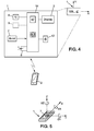
Figure 4 is a view of a schematic block diagram of the monitoring device, -
Figure 5 is a schematic view of a motion sensor included in the monitoring device, -
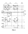
Figure 6 shows a time chart illustrating the detection of a wrist worn condition. -
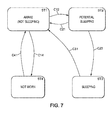
Figure 7 shows state chart illustrating the behaviour of the monitoring device. -
Figure 8 shows a general time chart illustrating a sleep condition detection, -
Figure 9 is analogous toFig 8 and shows a more detailed time chart illustrating a sleep condition detection, -
Figures 10A and 10B are analogous toFig 8 and show more detailed time charts illustrating an awakening condition detection. - In the figures, the same references denote identical or similar elements.
-
Figure 1 shows a user U wearing anactivity monitoring device 1 coupled to the body of the user. The illustrated activity monitor 1 may be formed as a small box, comprising a display system, to show the user activity. The activity monitor is able to inform the user on his activity, as walking, running, sleeping, stair climbing, etc.
The illustrated activity monitor 1 exhibits a weight below 10 grams, preferentially below 8 grams. Its size is also particularly small, the thickness being less than 8 mm, the length being less than 43 mm, the height being less than 22 mm, it is particularly easy and discreet to wear. The activity monitor 1 may be the product "Pulse"™ from the applicant Withings. Alternatively, the activity monitor 1 may be integrated in various other devices like a watch like "Smartwatch"™, eye glasses, or glasses like "Google glasses"™, in a headset, in a hearing aid or in an instrumented necklace. - As illustrated in
figures 2-3 , theactivity monitor 1 is adapted to be coupled to or attached to at least part of the body of the user. For example, the activity monitor 1 may be worn at the belt P4 of the user, or on a fixed bracelet at the wrist P1 of the user, or in the back pocket P5 of the user pant, or around the user waist, or clipped close to the chest P2 of the user, or clipped to a headset equipment P3. The activity monitor could be integrated in a device worn by the user like a headset or a hearing aid. - Advantageously, the activity monitor 1 may be worn at the
wrist 90, via awrist strap 5. Saidwrist strap 5 may have afront window 51 through which user can view the display of the activity monitor and aback window 52 that will be discussed later. - A
motion sensor 7 is provided in the activity monitor on order to sense the accelerations and movements of the user. The motion sensor is formed in the illustrated example as a multi-axis acceleration sensor 7 (also called 'accelerometer'). - The activity monitor may also comprise a
temperature sensor 4. In some body locations, thetemperature sensor 4 is intended to be close to the body of the user in order to sense an environmental temperature close to the user's skin. For example, illustrated onfigure 3 , thetemperature sensor 4 can be located at the back side of the device, opposite to thedisplay 3, and thanks to the back window of thewrist strap 5, the temperature sensor is facing the skin of the user at the user'swrist 90. - As illustrated on
figure 4 , the activity monitor 1 may include aprocessing unit 14 connected to themulti-axis acceleration sensor 7. Theprocessing unit 14 samples the signals outputted by the acceleration sensors. Theprocessing unit 14 computes said signals in order to assess user acceleration, movements and other information as this will be discussed below. - The activity monitor 1 comprises a
display 3 controlled by theprocessing unit 14. On the display, various data or metrics can be made available to the user such as number of steps, stairs climbed, calories burned, etc. The monitor may also display if the user is awake or asleep. The totalled metrics could be set to zero daily or on another basis depending on the configuration. - The activity monitor comprises a wireless communication interface 42 (here for example Bluetooth™, or Bluetooth™ Low Energy 'BLE' or the like), for sending collected data to a
second device 2 like a smartphone for example. - The activity monitor 1 is powered by an on-board source of
energy 8, for example a rechargeable battery. This battery supplies all the on-board elements in the device (thesensor 7, thedisplay 3 and theprocessing unit 14, etc.). - The activity monitor 1 also comprises the
abovementioned temperature sensor 4, and may also comprise variousother sensors 9 like an optical sensor, on On/Off switch, a touch pad area, environmental sensors, pollutants sensors, etc. - On
figure 5 the acceleration sensor oraccelerometer 7 is represented. In the illustrated example, it's a 6 axes sensor, able to measure linear accelerations along the three perpendicular directions X, Y, Z, and able to measure the rotation motion around the three perpendicular axis X, Y, Z. Miniature gyrometers are used for rotation motions θX, θY, θZ, preferably integrated in a single electronic package. - According to a first advantageous aspect of the invention, the monitoring device is able to recognise the condition when the user wears the monitoring device at the wrist, feature which relies on a counting of the number of the changes of predominant acceleration axis.
In other words, data on the changes of predominant acceleration axis of the activity monitor is used to determine if the user is wearing the activity monitor at the wrist or not, as this will be illustrated with the help ofFigure 6 . - The predominant axis is defined as the axis along which the acceleration force is the highest. At each instant the
monitoring device 1 senses each acceleration axis (X,Y,Z) and determines which one has the highest value, that is to say the predominant axis having the largest acceleration (step 'Wa' of the method). - If the activity monitor is still, only the gravity is sensed by the acceleration sensor; if the activity monitor is moved, the inertia forces are added to the gravity. However, in the case when the monitoring device is worn by a user U, the inertia forces (other than gravity) are alternate and the mean value is close to 0 or equal to 0.
- Advantageously, the monitoring device senses the 3 linear acceleration signals X,Y,Z, and those signals are filtered by a first low pass filter (analog or digital) having a cutoff frequency at about 3 or 4 Hz in order to discard all electrical disturbances and somewhat high frequency interferences that are not related with user's movements.
- Secondly and optionally , a second low pass filter having a cutoff frequency below 0,5 Hz or 0,25 Hz can be applied to determine absolute orientation of the device; such low pass filtering eliminates the acceleration induced by alternate inertia forces due to movements such that the filtered acceleration is substantially equal to gravity. The gravity reliably reflects the absolute orientation of the monitoring device.
- It should be noted that since the gravity is higher that most of mean values of X,Y,Z induced by the user's movements, the second low pass filter is not mandatory to determine the predominant axis among X,Y,Z.
- As a matter of fact, each of the acceleration signals can be divided into a first component outputted after a low pass filter (named DC component) and a second component called AC component obtained after suppression of the continuous DC component from the raw acceleration signal. The low pass filter can be the second low pass filter or another third low pass filter.
- It has been discovered by the inventor(s) that when the monitoring device is worn at the wrist, the changes of orientation are more numerous than in any other position on the body.
Therefore, the monitoring device determines each change of predominant axis when the largest acceleration changes from one axis to another, for example from X to Y, or from Y to Z, or from Z to Y, etc. (step 'Wb' of the method). - Then the monitoring device (the processing unit 14) computes the number of such changes per time period, referred to as Nbch, which is step 'Wc' of the method.
- Various methods can be used to output this ratio Nbch, for example a simple one consisting in incrementing a counter at each change of predominant axis and decrementing the same counter as the time passes by (which provides a natural time average filter).
- Another method consists in counting the number of changes of predominant axis per period of time. At the end of each period, a new number Nbt is calculated. Optionally, the new outputted number Nbch may be the result of a weighed average of Nbt and the previous value of Nbch. The period of time may be chosen according to various requirements, between 10 seconds and 150 seconds.
- Of course other more sophisticated methods to issue a filtered Nbch can be used. Further, the processing unit compares the number of changes of predominant axis per time period Nbch with a stored threshold named first predetermined threshold denoted CW1.
- In the present example, the predetermined threshold CW1 can be 5 changes per minute, or 8 changes per minute, or 10 changes per minute, or 15 changes per minute, or likewise may result from a learning procedure.
If Nbch > CW1, then a 'wrist worn condition' WWC is set to be true, meaning that the activity monitoring device is assumed to be actually worn at the user's wrist. This decision is referred to as step 'Wd' of the method. - Advantageously, the reference time period may be chosen between 30 seconds and 120 seconds. However, any other reference time period could be chosen.
Optionnally, the comparison Nbch > CW1 has to be verified for a first auxiliary time period TTA in order to make the decision WWC being true. - Further, at step Wd- of the method, the abovementioned wrist worn condition can be confirmed by a temperature correlation. More precisely, a predetermined temperature criterion TPC1 is provided; for example, said predetermined temperature criterion TPC1 may be a temperature interval comprised between Tbody1 and Tbody2. If the sensed temperature meets this first predetermined temperature criterion TPC1, comprised between Tbody1 and Tbody2 in the illustrated example, the processing unit can confirm the wrist worn condition WWC.
- Therefore, advantageously, the temperature sensor can be used to extend the wrist worn condition over time even if the user does not move substantially, by continuously monitoring the sensed temperature.
- More precisely, if the sensed temperature keeps meeting the above-mentioned predetermined temperature criterion TPC1 over a certain period of time TTB (may be called 'second auxiliary predetermined period' TTB), the wrist worn condition can be maintained over said period of time TTB. Thus, even if the wrist stays still, the wrist worn condition can be extended.
- Further, the method performed by the processing unit can also determine when the
activity monitor 1 is not worn anymore at the wrist by the user. More precisely, if the number of changes of predominant axis per time period Nbch is below a second predetermined threshold 'CW2', (instantaneously or over a third auxiliary period of time TTC, according to the filtering method relative to Nbch), then the wrist worn condition is assumed to be false. Advantageously, the second predetermined threshold CW2 is lower than the first predetermined threshold CW1. For example CW2 is equal to 50% of CW1 or preferably 25% of CW1. - Practically, the condition when the wrist worn condition is assumed to be false may correspond to the case when the user U has moved the monitoring device from the wrist to another body location, where linear acceleration is predominant and the direction of gravity relative to the device does not change much; It also corresponds to the case when the user does no wear the device anymore.
- It is also to be noted that whenever the acceleration sensor signals exhibits no change at all, that means that the monitoring device is not worn by the user and has been laid down still; in this case too, the wrist worn condition is assumed to be false.
- The knowledge of the wrist worn condition helps the monitoring device to compute more accurately the metrics of the various activities undertaken by the user. Appropriate corrections on caloric burn, distance travelled, stairs climbed, etc. can be made when the proper position on the body is known. In the present case, the wrist worn condition is determined, nearly in real time, for the benefits of accurate calculations.
- Referring now to
figure 6 , various data are illustrated, the number of changes of predominant axis Nbch, the sensed temperature STemp, the sensed acceleration on the 3 axis X,Y,Z, and the resulting information i.e. the wrist worn condition WWC. - In the first sequence H1, the wrist worn condition WWC is initially indefinite, and the number of changes of predominant axis Nbch is monitored.
- XYZ charts exhibit the predominant acceleration axis after the low pass filtering which result in squared signals 71. Also the
AC component 72 of each signal X,Y,Z are shown. - At the time HT1, when Nbch exceeds the predetermined threshold CW1, (with or without the time window confirmation TTA), WWC is set to true, regardless of the temperature information and the acceleration information.
- The second sequence H2 illustrates the temperature correlation as explained above, between instants HT20 and HT21, the sensed temperature meets the temperature criterion TPC1. In a simple case as illustrated, the temperature criterion TPC1 corresponds to the condition when the temperature is comprised between two temperature thresholds, namely a first predetermined temperature threshold Tbody1 and a second predetermined temperature threshold Tboby2.
- If the sensed temperature keeps meeting the temperature criterion TPC1, this allows to maintain the wrist worn condition at true, regardless of the values of Nbch and the acceleration information.
- In the present example, the first and second predetermined thresholds Tbody1 and Tboby2 can be respectively 25°C and 35°C, but of course other values can be considered, and those threshold values may result from a learning procedure.
- It should be noted that a second temperature criterion TPC2 is defined, the use of which will be detailed below.
- The third sequence H3 illustrates a sequence when WWC becomes false on a condition of the value of Nbch becoming sufficiently low.
- At instant HT3, Nbch becomes lower than the second predetermined threshold CW2, and therefore the processing unit assumes that the monitoring device is worn at a body position different from the wrist position (WWC is set to False). Optionally, the Nbch<CW2 condition has to be verified along the TTC time window (relative to the above mentioned third auxiliary predetermined time period).
- At instant HT4, Nbch becomes again higher than CW1 and the condition WWC is set to true again.
- The fourth sequence H4 illustrates a sequence when WWC becomes false on a condition that the monitoring device is laid down and not worn by the user. In this particular case, the AC component of the three accelerometers are null. Thus the processing unit sets WWC to 'False' after a predefined time with AC components substantially null.
- It should be noted that it is not excluded to use the girometer data, namely rotation motions θX, θY, θZ, to compute a change of orientation ratio.
- Besides, it should be noted that the method explained above can also be used to detect more generally that the monitoring device is worn at an extremity of the user's body. More precisely, the method similar to the one used for the wrist position can be used to detect that the monitoring device is worn at the foot of the user. The number of changes of orientation per period of time is computed similarly, different thresholds CW1 CW2 are used (preferably lower values), and this is combined with the level of the linear acceleration signals which have a different pattern when the monitoring device is worn at the foot (higher peak values).
- According to a second advantageous aspect of the invention, the monitoring device is able to recognise various type of user's activities, including sleep.
- Indeed, the monitoring device is intended to monitor all the phases of the user's life, including rest and sleep, and to report to the user the duration of sleep, quality of sleep etc.
- The accelerometer data is collected continuously by the
processing unit 14 of themonitoring device 1. As already explained, the acceleration signals can be divided into a first component outputed after the low pass filter and a second component called AC component after suppression of the continuous DC component. In the following, we focus on the AC components. Each linear AC component can be time-averaged with a rolling average window. - Since the motion sensor is formed as a 3-axis accelerometer (X,Y,Z) the current sensed level of activity AL is determined by summing the average signals of the 3 linear accelerometers, in particular AC components for each linear direction (step 'Sa' of the method).
- Three activity standards are defined: a low standard of activity (AS1), a medium standard of activity (AS2) and a high standard of activity (AS3). Those levels of activity are defined by two thresholds: LAL (predefined low level of activity) and MAL (predefined medium level of activity), as shown in
Figure 8 . - Besides the definition of the levels of activities, the monitoring device also defines 4 states (ST1: AWAKE, ST2:POTENTIAL_SLEEPING, ST3:SLEEPING, ST4: NOT WORN) that will be detailed below, referring to
Figure 7 . The state chart illustrated inFigure 7 comprises boxes that represent states (ST1-ST4) and arrows CXY that represent logical conditions of transition from one state to another. - Under another perspective, the
activity monitor 1 determines via the temperature sensor 4 a current temperature (T) and a first temperature profile (TPR1) over time (step 'Sb' of the method). - The temperature measurement gives complementary information to corroborate acceleration data, as explained below.
- If the sensed level of activity is below the predefined low level of activity (LAL) for at least a first period of time TT1, a state 'POTENTIAL_SLEEP' ST2 is assumed.
- It may be complemented by one of the two following conditions: if the first temperature profile TPR1 meets a first predetermined temperature criterion TPC1 over the first period of time TT1, then a state 'POTENTIAL_SLEEP' is confirmed.
- Likewise, if the first temperature profile TPR1 meets first predetermined temperature criterion TPC1 over the second period of time TT2 then a state 'SLEEPING' ST3 is confirmed.
- Advantageously, the second period of time TT2 starts as soon as a state 'POTENTIAL_SLEEP' is assumed or confirmed. Of course, if too much activity is sensed during this period, transition C21 as explained below is activated, and the current state becomes again AWAKE ST1.
- If the user wears the activity monitor (wrist or elsewhere) the sensed temperature profile is expected to meet the first predetermined temperature criterion TPC1. For example the temperature could be included in the interval Tbody1 and Tbody2.
- If the user doesn't wear the
activity monitor 1, the detected temperature would be lower than Tbody1. Tbody1 can be set to 25°C or similar value. - Turning now to
figure 7 , to begin with, any important detected movement over a certain time results in the assumption of state ST1 AWAKE, this is illustrated by transitions C21, C31, C41, and shown byfigure 10A . - Transition C14 (AWAKE to NOT WORN) is assumed when no movement is detected and the temperature meets the second predetermined temperature criterion TPC2. This means the activity monitor lies still somewhere and is not worn.
- This second predetermined temperature criterion TPC2 may consist in a simple temperature condition namely STemp < Tbody1, or any other threshold value different from Tbody1, this threshold being advantageously set to 22°C or 23°C or 24°C. Alternatively, the second predetermined temperature criterion TPC2 may also include a condition on temperature change (see below).
- Transition C12 (AWAKE to POTENTIAL_SLEEP) is assumed when the sensed level of activity is below the predefined low level of activity (LAL) for at least a first period of time TT1, and if the sensed temperature meets the first temperature criterion TPC1 (here between Tbody1 and Tbody2).
- Transition C23 (POTENTIAL_SLEEP to SLEEPING) is assumed when the sensed level of activity does not exceed another predefined level of activity (for example MAL) more than another predefined period of time TT2, and if the sensed temperature keeps meeting the first temperature criterion TPC1 (here between Tbody1 and Tbody2).
- Whenever the transition C23 becomes true, the data recorded in the state ST2 are confirmed to be effective sleep. In contrary, whenever the transition C21 terminates the ST2:POTENTIAL_SLEEP, the data recorded in that state ST2 is not considered to be effective sleep.
- Therefore, whenever the transition C23 becomes true, the instant considered to be the moment when the user fell asleep is the previous time of transition C12 (the ST2 is considered a posteriori to be effective sleep).
- Also, the instant considered to be the moment when the user emerges from sleep is the next transition C31.
- Therefore, the
processing unit 14 is able to accurately calculate the duration of sleep between the above-mentioned transitions C12 and C31, (provided that ST2 was followed directly by ST3 (C23)). - Of course total duration of sleep for one night is calculated as the concatenation of several sleep phases whenever the user awoke once or more during the night.
- It should be noted that, during states ST2 and ST3, whenever a movement resulting in a level of activity above the predefined low level LAL, as illustrated at instant TT9, this does not result in exiting the current state.
- Transition C31 (referred to as 'wake activity criterion') is now explained in more details, referring to
figures 10A and 10B . The processing unit will decide an end of the sleeping phase (SLEEPING to AWAKE) according to different possible conditions, based on a certain activity level AL or on a sensed temperature condition STemp. - One of the condition is that the sensed level of activity AL is above the predefined low level of activity LAL for at least a third period of time TT3.
- Another condition can be that the sensed level of activity is above a medium level of activity MAL for at least a fourth period of time TT4.
- Still another condition can be that the sensed level of activity is above a high level of activity HAL for at least another, short, period of time TT5, let's say several seconds or more.
- Yet another condition relates to the sensed temperature; the wake activity criterion will be met if the sensed temperature meets the already mentioned second predetermined temperature criterion TPC2.
- This second predetermined temperature criterion TPC2 may consist in a simple temperature condition namely STemp < Tbody1, or any other threshold value different from Tbody1, this threshold being advantageously set to 23°C or 24°C or 25°C.
This is shown onfig 10B at instant HT7.
Alternatively, the second predetermined temperature criterion TPC2 may also include a condition on temperature change. More precisely, the processing unit calculates a ratio of change of sensed temperature per time unit TCR, and the wake activity criterion also comprises a condition in which said ratio of change of sensed temperature per time unit exceeds a predefined temperature change threshold TCR0. Additionally, the absolute temperature condition can be combined with the above mentioned condition on temperature change. For example, conditions TCR>TCR0 and STemp<TTH0 can be combined, with TTH0 set to 26°C. - Regarding transition C21, it includes conditions already explained for transition C31, but also conditions on temperature. For example if POTENTIAL_SLEEP(ST2) is the current state, and the current temperature profile is being monitored, two cases may arise:
- if current temperature profile meets the criterion TPC1, then user is considered to be in the sleeping state ST3 as already explained, but,
- if the current temperature profile does not meet the criterion TPC1, then user is considered still awake (transition C21 activates).
- Thanks to the monitoring of the temperature, and according to the fifth aspect of the present invention, it is disclosed a method to determine that the user is awake with a very low level of activity. Advantageously, this allows to distinguish a sleep state of the user from a very low active but still awake state. More precisely, if the user is sitting on a sofa watching TV, then the level of activity will be below the predefined low level of activity LAL, however, the temperature profile will probably not meet the first temperature criterion TPC1. Furthermore, this little active awake state can be confirmed by data that are coming from other auxiliary devices.
- It should be noted that when the user goes to sleep, the most likely the position for the monitoring device is the wrist position, and therefore the temperature information mostly reflects the skin temperature.
- According to the third aspect of the present invention, the proposed method is configured to determine a current coupling position of the monitoring device on the user's body among a plurality of possible body coupling positions. Said plurality of possible body coupling positions includes extremities (hand, wrist, foot), upper arm, upper leg, hip, waist, torso, neck, head.
- The method comprises the steps of collecting the accelerometer signals, analysing time and frequency characteristics of the collected signals, comparing said characteristics to predefined patterns, and then deciding the most likely body coupling position.
- Preferably the plurality of possible body coupling positions includes extremities (hand, wrist, foot), upper arm, upper leg, hip, waist, torso, neck, head. The predefined patterns may include criteria or thresholds on the following items : predominant frequency, frequency of orientation changes, amplitude, symmetry or the symmetry versus arrange value, etc.
- Hip coupling position will be assumed (decided to be the most likely) if acceleration module (sum of 3 axis linear acceleration signals) is dissymmetric from one step to another, and the average level is crossed at each step.
- Neck and/or head coupling position will be assumed if acceleration module is symmetric from one step to another (sinus like), and the average level is crossed at each step.
- Wrist and/or foot coupling position will be assumed if the acceleration axis which is mostly vertically oriented is frequently changing (see details in the table).
- Upper arm and/or upper leg coupling position will be assumed if the acceleration axis which is mostly vertically oriented is changing but less frequently than on the wrist.
- According to a variant of the third aspect of the present invention, the proposed method is configured to determine, using also the temperature signal, on the one hand a current coupling position of the monitoring device on the user's body among a plurality of possible body coupling positions and to concurrently determine on the other hand the current type of activity undertaken by the user among a plurality of possible activities.
The plurality of possible body coupling positions are the same as above, whereas the plurality of possible user's activities may include sleeping, walking, running, cycling, swimming, golfing, doing racket sport, etc. - The predefined patterns may include criteria or thresholds, with acceleration and temperature signal correlation, on the one hand acceleration signals such as predominant frequency, frequency of orientation changes, amplitude, symmetry or the symmetry versus average value, etc., and the other hand predefined temperature thresholds regarding temperature signal.
- A detailed decision matrix is given in Table 1 at the end of the present specification, it is to be noted that the content of said Table 1 is non-limiting. In this table, cross conditions correlating acceleration signals and temperature signals allows the monitoring unit to infer both the current position of the monitoring device and the current activity of the user.
- According to a fourth aspect of the present invention, the proposed method is configured to correlate data from various external devices, besides the already mentioned communication with a
smart phone 2. More precisely, themonitoring device 1 can exchange data with various external devices (in particular receive from) through the short-range wireless communication interface. More precisely other devices located in the same room or in the vicinity of the monitoring device can send additional information to themonitoring device 1 in order to make the decision on the body coupling position and/or on the user activity faster and more reliable. - Said various external devices may include the following devices :
- an air quality sensor (for example CO2 or VOC sensor), which is useful to recognize and/or confirm the sleep activity, knowing that CO2/VOC level in a room is directly correlated with number of people in a room; a strong increase of CO2/VOC level in the bedroom (>200ppm) shows presence of one person, a second increase shows presence of a second person... Inversely a strong decrease in CO2/VOC level means that the door was opened and someone left the room; hence if the CO2/VOC level is below a 1 person level, therefore this confirms the awakening of the user;
- a sleep sensor arranged on a bed (pneumatic, piezoelectric, sound, video), which is also useful to recognize and/or confirm the sleep activity, since such sleep sensor allows to detect somebody standing up from bed, noise, movement of the user in bed; if the sleep sensor senses nobody in the bed this confirms the awakening of the user;
- a geo-location sensor, such as GPS, (housed on a smartphone, smartwatch or something similar), which is useful to recognize and/or confirm running and/or sport activity, since said geo-location sensor is able to provide accurate location and travel speed,
- an image/video apparatus, such as a home video monitoring system, said video system being able to analyze the captured images, in particular images of the user, and spot the location and position of the activity monitoring device on the user, and transmit the related data,
- a weighing scale with user detection, which is useful to determine a wake-up condition of the user, since if the user is detected on the scale, the user is awake.
- Thanks to the above methods, the knowledge of the current coupling position of the monitoring device on the user's body and the knowledge activity undertaken by the user allows the monitoring device to improve the accuracy of the calculation regarding number of steps, caloric burning, travelled distance, etc.
TABLE 1 When worn on the torso sleep Activity level scores (see specification above) High temperature (above threshold TTH3) walk (including golf and any sport where walking is needed) Sequence of max and min in the 3 axis acceleration module signal, below adequate frequency threshold FTH1, above adequate amplitude threshold ATH1 Any temperature (not relevant) run (including any sports where running is needed) Sequence of max and min in the 3 axis module signal, above adequate frequency threshold FTH2, above adequate amplitude threshold ATH2 Any temperature (not relevant) cycle Random high frequency acceleration module Not relevant when worn at the extremities sleep Same than sleep/torso case above, High temperature (above threshold TTH3) walk Same than walk/torso case above in Table1, with different amplitude threshold May be used to confirm a decision run Same than run/torso case above in Table1, with different amplitude threshold temperature increase increases likelihood (but is not mandatory swim The acceleration axis which is mostly vertically oriented is changing with a relatively fixed period Any temperature (not relevant) cycle Same than cycle/torso case with higher amplitude acceleration module Any temperature (not relevant) racket sport The acceleration axis which is mostly vertically oriented is changing frequently, on a non basis and acceleration amplitude is high (above given threshold) temperature increase increases likelihood (but is not mandatory golf acceleration caracteristic pattern of swing recognized by machine learning, separated by short walking period Any temperature (not relevant)
Claims (14)
- Method to detect a sleep state of a user (U) wearing a personal activity monitor (1), said personal activity monitor comprising a motion sensor (7), a processor unit (14) and a temperature sensor (4), the method comprising the steps of :Sa- determine via the motion sensor a current sensed level of activity (AL), and compare this current level of activity to a predefined low level of activity (LAL),Sb- determine via the temperature sensor a current temperature (STemp) at the vicinity of the activity monitor, and a first temperature profile (TPR1),Sc- if the sensed level of activity is below the predefined low level of activity (LAL) for at least a first period of time (TT1) and if concurrently the first temperature profile meets a first predetermined temperature criterion (TPC1) over the first period of time (TT1) or over a second period of time (TT2), then infer that the personal activity monitor is actually worn by the user and that the user in a sleep state (ST2,ST3), thereby, such method allows the device to reliably determine the user's effective sleep.
- Method according to claim 2, to detect a sleep phase of a user (U) wearing the personal activity monitor (1), further comprising :- infer, from steps Sa to Sc, that the user has entered a sleep phase, as soon as the sleep state is determined,
Sd- if the sensed level of activity and/or sensed temperature meets a wake activity criterion, infer that the user has emerged from sleep,
Se- calculate the sleep duration of the user, between instants of entering and emerging from sleep. - Method according to claim 2, in which in step Sd-, the wake activity criterion comprises at least a condition of the sensed level of activity above the predefined low level of activity (LAL) for at least a third period of time (TT3), or a condition of the sensed level of activity above a second level of activity (MAL) for at least a fourth period of time (TT4).
- Method according to claim 2, in which in step Sd-, the wake activity criterion comprises at least a condition when the sensed temperature (STemp) meets a second predetermined temperature criterion (TPC2), preferably the sensed temperature (STemp) is below a first predefined temperature threshold (Tbody1).
- Method according to claim 4, wherein the processing unit further calculates a ratio of change of sensed temperature per time unit (TCR), and wherein the wake activity criterion also comprises a condition in which said ratio of change of sensed temperature per time unit exceeds a predefined temperature change threshold (TCR0).
- Method according to claim 1 or 2, in which the first predetermined temperature criterion (TPC1) is a temperature interval comprised between a first predefined temperature threshold (Tbody1) and a second predefined temperature threshold (Tbody2).
- Method according to claim 1 or 2, in which the motion sensor is formed as a 3-axis accelerometer (X,Y,Z) and the current sensed level of activity (AL) is determined by summing the average signals of the AC components of each 3 linear accelerometers.
- A method to determine a position of a personal activity monitor (1) worn by a user (U), such personal activity monitor comprising a motion sensor (7) formed as an at least 3-axis accelerometer (X,Y,Z) and a processor unit (14),
the method comprising the steps of :Wa- identify at each instant which axis (X,Y,Z) senses the largest acceleration,Wb- determine a change of predominant axis when the largest acceleration changes from one axis to another,Wc- determine a number of changes of predominant axis per time period (Nbch),Wd- define a wrist worn condition (WWC), meaning that the personal activity monitor is worn at the wrist of the user, and, if the number of changes of predominant axis per time period (Nbch) exceeds a first predetermined threshold (CW1), infer that the wrist worn condition is true; thereby, such method allows to determine that the personal activity monitor is worn or not at the wrist of the user. - Method according to claim 8, in which in step Wa-, the 3 linear acceleration signals are filtered by a low pass filter, such that the largest acceleration is provided by gravity.
- Method according to claim 8, further comprising a step We-, in which it is inferred that the wrist worn condition is or become false, if the number of changes of predominant axis per time period (Nbch) is below a second predetermined threshold (CW2).
- Method according to claim 8, wherein the second predetermined threshold (CW2) is lower than the first predetermined threshold (CW1).
- Method according to claim 8, in which the number of changes of predominant axis is computed periodically over the last elapsed period.
- Method according to claim 8, wherein the method further comprises the use of a temperature sensor (4) enclosed in the personal activity monitor, wherein in step Wd-, the wrist worn condition is maintained over a certain period of time (TTB) if a sensed temperature sensed by the temperature sensor meets a first predetermined temperature criterion (TPC1) over said certain period of time (TTB).
- The method according to claim 13, in which the first predetermined temperature criterion (TPC1) is a temperature interval comprised between a first predefined temperature threshold (Tbody1) and a second predefined temperature threshold (Tbody2).
Applications Claiming Priority (1)
| Application Number | Priority Date | Filing Date | Title |
|---|---|---|---|
| US14/251,239 US10441212B2 (en) | 2014-04-11 | 2014-04-11 | Method to determine positions and states of an activity monitoring device |
Publications (3)
| Publication Number | Publication Date |
|---|---|
| EP2929837A2 true EP2929837A2 (en) | 2015-10-14 |
| EP2929837A3 EP2929837A3 (en) | 2016-03-23 |
| EP2929837B1 EP2929837B1 (en) | 2022-09-28 |
Family
ID=53016461
Family Applications (1)
| Application Number | Title | Priority Date | Filing Date |
|---|---|---|---|
| EP15162939.1A Active EP2929837B1 (en) | 2014-04-11 | 2015-04-09 | Method to determine positions and states of an activity monitoring device |
Country Status (2)
| Country | Link |
|---|---|
| US (1) | US10441212B2 (en) |
| EP (1) | EP2929837B1 (en) |
Cited By (4)
| Publication number | Priority date | Publication date | Assignee | Title |
|---|---|---|---|---|
| EP2989973A1 (en) * | 2014-08-26 | 2016-03-02 | Samsung Electronics Co., Ltd. | Electronic device and sleep monitoring method in electronic device |
| CN107137091A (en) * | 2017-06-26 | 2017-09-08 | 哈尔滨理工大学 | A kind of infantal sleeping monitor |
| WO2018082959A1 (en) * | 2016-11-02 | 2018-05-11 | Koninklijke Philips N.V. | Sleep monitoring |
| EP3357412A1 (en) * | 2017-02-07 | 2018-08-08 | Koninklijke Philips N.V. | Sleep monitoring |
Families Citing this family (74)
| Publication number | Priority date | Publication date | Assignee | Title |
|---|---|---|---|---|
| US10335060B1 (en) | 2010-06-19 | 2019-07-02 | Dp Technologies, Inc. | Method and apparatus to provide monitoring |
| US8620617B2 (en) | 2010-09-30 | 2013-12-31 | Fitbit, Inc. | Methods and systems for interactive goal setting and recommender using events having combined activity and location information |
| US8805646B2 (en) | 2010-09-30 | 2014-08-12 | Fitbit, Inc. | Methods, systems and devices for linking user devices to activity tracking devices |
| US8954290B2 (en) | 2010-09-30 | 2015-02-10 | Fitbit, Inc. | Motion-activated display of messages on an activity monitoring device |
| US8738321B2 (en) | 2010-09-30 | 2014-05-27 | Fitbit, Inc. | Methods and systems for classification of geographic locations for tracked activity |
| US8762101B2 (en) | 2010-09-30 | 2014-06-24 | Fitbit, Inc. | Methods and systems for identification of event data having combined activity and location information of portable monitoring devices |
| US8762102B2 (en) | 2010-09-30 | 2014-06-24 | Fitbit, Inc. | Methods and systems for generation and rendering interactive events having combined activity and location information |
| US8954291B2 (en) | 2010-09-30 | 2015-02-10 | Fitbit, Inc. | Alarm setting and interfacing with gesture contact interfacing controls |
| US10004406B2 (en) | 2010-09-30 | 2018-06-26 | Fitbit, Inc. | Portable monitoring devices for processing applications and processing analysis of physiological conditions of a user associated with the portable monitoring device |
| US8694282B2 (en) | 2010-09-30 | 2014-04-08 | Fitbit, Inc. | Methods and systems for geo-location optimized tracking and updating for events having combined activity and location information |
| US8615377B1 (en) | 2010-09-30 | 2013-12-24 | Fitbit, Inc. | Methods and systems for processing social interactive data and sharing of tracked activity associated with locations |
| US9241635B2 (en) | 2010-09-30 | 2016-01-26 | Fitbit, Inc. | Portable monitoring devices for processing applications and processing analysis of physiological conditions of a user associated with the portable monitoring device |
| US8744803B2 (en) | 2010-09-30 | 2014-06-03 | Fitbit, Inc. | Methods, systems and devices for activity tracking device data synchronization with computing devices |
| US9148483B1 (en) | 2010-09-30 | 2015-09-29 | Fitbit, Inc. | Tracking user physical activity with multiple devices |
| US10983945B2 (en) | 2010-09-30 | 2021-04-20 | Fitbit, Inc. | Method of data synthesis |
| US9390427B2 (en) | 2010-09-30 | 2016-07-12 | Fitbit, Inc. | Methods, systems and devices for automatic linking of activity tracking devices to user devices |
| US8712724B2 (en) | 2010-09-30 | 2014-04-29 | Fitbit, Inc. | Calendar integration methods and systems for presentation of events having combined activity and location information |
| US8738323B2 (en) | 2010-09-30 | 2014-05-27 | Fitbit, Inc. | Methods and systems for metrics analysis and interactive rendering, including events having combined activity and location information |
| US11243093B2 (en) | 2010-09-30 | 2022-02-08 | Fitbit, Inc. | Methods, systems and devices for generating real-time activity data updates to display devices |
| US9459597B2 (en) | 2012-03-06 | 2016-10-04 | DPTechnologies, Inc. | Method and apparatus to provide an improved sleep experience by selecting an optimal next sleep state for a user |
| US9641239B2 (en) | 2012-06-22 | 2017-05-02 | Fitbit, Inc. | Adaptive data transfer using bluetooth |
| US9728059B2 (en) | 2013-01-15 | 2017-08-08 | Fitbit, Inc. | Sedentary period detection utilizing a wearable electronic device |
| US9594354B1 (en) | 2013-04-19 | 2017-03-14 | Dp Technologies, Inc. | Smart watch extended system |
| EP3074838A4 (en) * | 2013-11-29 | 2017-08-02 | Motiv Inc. | Wearable computing device |
| US11963792B1 (en) | 2014-05-04 | 2024-04-23 | Dp Technologies, Inc. | Sleep ecosystem |
| US9943241B2 (en) | 2014-06-12 | 2018-04-17 | PhysioWave, Inc. | Impedance measurement devices, systems, and methods |
| US9949662B2 (en) | 2014-06-12 | 2018-04-24 | PhysioWave, Inc. | Device and method having automatic user recognition and obtaining impedance-measurement signals |
| US9546898B2 (en) | 2014-06-12 | 2017-01-17 | PhysioWave, Inc. | Fitness testing scale |
| US10130273B2 (en) | 2014-06-12 | 2018-11-20 | PhysioWave, Inc. | Device and method having automatic user-responsive and user-specific physiological-meter platform |
| US9693696B2 (en) | 2014-08-07 | 2017-07-04 | PhysioWave, Inc. | System with user-physiological data updates |
| EP3213671A4 (en) * | 2014-10-31 | 2018-02-28 | Fujitsu Limited | State display method, program, and state display device |
| US9448536B1 (en) * | 2015-03-04 | 2016-09-20 | Dp Technologies, Inc. | Self-winding mechanical watch with activity tracking |
| KR102318887B1 (en) * | 2015-03-06 | 2021-10-29 | 삼성전자주식회사 | Wearable electronic device and method for controlling thereof |
| US11883188B1 (en) | 2015-03-16 | 2024-01-30 | Dp Technologies, Inc. | Sleep surface sensor based sleep analysis system |
| US10945671B2 (en) | 2015-06-23 | 2021-03-16 | PhysioWave, Inc. | Determining physiological parameters using movement detection |
| CN105425940B (en) * | 2015-10-23 | 2019-12-06 | 安徽华米信息科技有限公司 | Method and device for determining wearing state of bracelet and wearable device |
| US10436630B2 (en) | 2015-11-20 | 2019-10-08 | PhysioWave, Inc. | Scale-based user-physiological data hierarchy service apparatuses and methods |
| US10395055B2 (en) | 2015-11-20 | 2019-08-27 | PhysioWave, Inc. | Scale-based data access control methods and apparatuses |
| US10980483B2 (en) | 2015-11-20 | 2021-04-20 | PhysioWave, Inc. | Remote physiologic parameter determination methods and platform apparatuses |
| US11561126B2 (en) | 2015-11-20 | 2023-01-24 | PhysioWave, Inc. | Scale-based user-physiological heuristic systems |
| US10553306B2 (en) | 2015-11-20 | 2020-02-04 | PhysioWave, Inc. | Scaled-based methods and apparatuses for automatically updating patient profiles |
| US10923217B2 (en) | 2015-11-20 | 2021-02-16 | PhysioWave, Inc. | Condition or treatment assessment methods and platform apparatuses |
| US10827320B2 (en) | 2015-12-04 | 2020-11-03 | Lenovo (Singapore) Pte. Ltd. | Presentation of information based on whether user is in physical contact with device |
| CN105496416B (en) * | 2015-12-28 | 2019-04-30 | 歌尔股份有限公司 | A kind of recognition methods of human motion state and device |
| RU168584U1 (en) * | 2016-01-11 | 2017-02-09 | Алексей Викторович Горбунов | DEVICE FOR REGISTRATION OF HUMAN MOTOR ACTIVITY |
| CN105758452B (en) * | 2016-02-04 | 2018-05-15 | 歌尔股份有限公司 | The wearing state detection method and device of a kind of wearable device |
| US10080530B2 (en) | 2016-02-19 | 2018-09-25 | Fitbit, Inc. | Periodic inactivity alerts and achievement messages |
| US10390772B1 (en) | 2016-05-04 | 2019-08-27 | PhysioWave, Inc. | Scale-based on-demand care system |
| JP6553824B2 (en) * | 2016-05-09 | 2019-07-31 | コーニンクレッカ フィリップス エヌ ヴェKoninklijke Philips N.V. | Sleep monitoring |
| US10215619B1 (en) | 2016-09-06 | 2019-02-26 | PhysioWave, Inc. | Scale-based time synchrony |
| WO2018053677A1 (en) * | 2016-09-20 | 2018-03-29 | 华为技术有限公司 | Method of detecting whether smart device is being worn, and smart device |
| CN106510719B (en) * | 2016-09-30 | 2023-11-28 | 歌尔股份有限公司 | User gesture monitoring method and wearable device |
| CN106510641B (en) * | 2016-12-19 | 2019-10-11 | 姚健欣 | A kind of method and system detecting human body difference sleep stage |
| US10699247B2 (en) | 2017-05-16 | 2020-06-30 | Under Armour, Inc. | Systems and methods for providing health task notifications |
| FR3066900B1 (en) * | 2017-06-02 | 2024-08-02 | Neovia | DEVICE AND METHOD FOR DETECTING THE AWAKENING OF AN ANIMAL |
| US10767878B2 (en) | 2017-11-21 | 2020-09-08 | Emerson Climate Technologies, Inc. | Humidifier control systems and methods |
| US11486593B2 (en) | 2018-04-20 | 2022-11-01 | Emerson Climate Technologies, Inc. | Systems and methods with variable mitigation thresholds |
| US12259148B2 (en) | 2018-04-20 | 2025-03-25 | Copeland Lp | Computerized HVAC filter evaluation system |
| US12018852B2 (en) | 2018-04-20 | 2024-06-25 | Copeland Comfort Control Lp | HVAC filter usage analysis system |
| US12311308B2 (en) | 2018-04-20 | 2025-05-27 | Copeland Lp | Particulate-matter-size-based fan control system |
| WO2019204792A1 (en) | 2018-04-20 | 2019-10-24 | Emerson Climate Technologies, Inc. | Coordinated control of standalone and building indoor air quality devices and systems |
| WO2019204789A1 (en) | 2018-04-20 | 2019-10-24 | Emerson Climate Technologies, Inc. | Indoor air quality sensor calibration systems and methods |
| US11371726B2 (en) | 2018-04-20 | 2022-06-28 | Emerson Climate Technologies, Inc. | Particulate-matter-size-based fan control system |
| WO2019204788A1 (en) | 2018-04-20 | 2019-10-24 | Emerson Climate Technologies, Inc. | Systems and methods for adjusting mitigation thresholds |
| WO2019204779A1 (en) | 2018-04-20 | 2019-10-24 | Emerson Climate Technologies, Inc. | Indoor air quality and occupant monitoring systems and methods |
| US11609004B2 (en) | 2018-04-20 | 2023-03-21 | Emerson Climate Technologies, Inc. | Systems and methods with variable mitigation thresholds |
| CN110717349A (en) * | 2018-07-11 | 2020-01-21 | 深圳纬目信息技术有限公司 | Table mat and state monitoring method |
| US11793455B1 (en) | 2018-10-15 | 2023-10-24 | Dp Technologies, Inc. | Hardware sensor system for controlling sleep environment |
| CN112764518A (en) * | 2019-10-21 | 2021-05-07 | Oppo广东移动通信有限公司 | Control method, wearable device and storage medium |
| CN113520306B (en) * | 2020-04-17 | 2024-03-22 | 青岛海尔空调器有限总公司 | Human sleep state monitoring method and intelligent household device |
| EP3906853A1 (en) | 2020-05-05 | 2021-11-10 | Withings | Method and device to determine sleep apnea of a user |
| CN112802306B (en) * | 2021-01-14 | 2022-03-22 | 淮阴工学院 | A safety detection system for power dispatch automation system |
| CN113662511A (en) * | 2021-08-18 | 2021-11-19 | 歌尔科技有限公司 | Wearable device sleep monitoring method, device, equipment and storage medium |
| CN117298545A (en) * | 2023-11-08 | 2023-12-29 | 广东乐康安体育科技有限公司 | Swimming state monitoring device and method |
Citations (1)
| Publication number | Priority date | Publication date | Assignee | Title |
|---|---|---|---|---|
| EP2255209A1 (en) | 2008-01-28 | 2010-12-01 | Garmin Switzerland GmbH | Method and apparatus for determining the attachment position of a motion sensing apparatus |
Family Cites Families (9)
| Publication number | Priority date | Publication date | Assignee | Title |
|---|---|---|---|---|
| US8872646B2 (en) * | 2008-10-08 | 2014-10-28 | Dp Technologies, Inc. | Method and system for waking up a device due to motion |
| US20100100004A1 (en) * | 2008-10-16 | 2010-04-22 | Koninklijke Nederlandse Akademie Van Wetenschappen | Skin Temperature Measurement in Monitoring and Control of Sleep and Alertness |
| JP2010099383A (en) * | 2008-10-27 | 2010-05-06 | Omron Healthcare Co Ltd | Electronic blood pressure meter |
| US20100210975A1 (en) * | 2009-01-21 | 2010-08-19 | SwimSense, LLC | Multi-state performance monitoring system |
| EP2635938B1 (en) * | 2010-11-01 | 2022-09-07 | NIKE Innovate C.V. | Wearable device assembly having athletic functionality |
| US10463300B2 (en) * | 2011-09-19 | 2019-11-05 | Dp Technologies, Inc. | Body-worn monitor |
| EP2816950A4 (en) * | 2012-02-22 | 2015-10-28 | Aclaris Medical Llc | Physiological signal detecting device and system |
| US9459597B2 (en) * | 2012-03-06 | 2016-10-04 | DPTechnologies, Inc. | Method and apparatus to provide an improved sleep experience by selecting an optimal next sleep state for a user |
| US20140180595A1 (en) * | 2012-12-26 | 2014-06-26 | Fitbit, Inc. | Device state dependent user interface management |
-
2014
- 2014-04-11 US US14/251,239 patent/US10441212B2/en active Active
-
2015
- 2015-04-09 EP EP15162939.1A patent/EP2929837B1/en active Active
Patent Citations (1)
| Publication number | Priority date | Publication date | Assignee | Title |
|---|---|---|---|---|
| EP2255209A1 (en) | 2008-01-28 | 2010-12-01 | Garmin Switzerland GmbH | Method and apparatus for determining the attachment position of a motion sensing apparatus |
Cited By (6)
| Publication number | Priority date | Publication date | Assignee | Title |
|---|---|---|---|---|
| EP2989973A1 (en) * | 2014-08-26 | 2016-03-02 | Samsung Electronics Co., Ltd. | Electronic device and sleep monitoring method in electronic device |
| WO2018082959A1 (en) * | 2016-11-02 | 2018-05-11 | Koninklijke Philips N.V. | Sleep monitoring |
| US10517526B2 (en) | 2016-11-02 | 2019-12-31 | Koninklijke Philips N.V. | Sleep monitoring |
| JP2020500051A (en) * | 2016-11-02 | 2020-01-09 | コーニンクレッカ フィリップス エヌ ヴェKoninklijke Philips N.V. | Sleep monitoring |
| EP3357412A1 (en) * | 2017-02-07 | 2018-08-08 | Koninklijke Philips N.V. | Sleep monitoring |
| CN107137091A (en) * | 2017-06-26 | 2017-09-08 | 哈尔滨理工大学 | A kind of infantal sleeping monitor |
Also Published As
| Publication number | Publication date |
|---|---|
| US20150289802A1 (en) | 2015-10-15 |
| EP2929837A3 (en) | 2016-03-23 |
| EP2929837B1 (en) | 2022-09-28 |
| US10441212B2 (en) | 2019-10-15 |
Similar Documents
| Publication | Publication Date | Title |
|---|---|---|
| EP2929837B1 (en) | Method to determine positions and states of an activity monitoring device | |
| US9808185B2 (en) | Movement measure generation in a wearable electronic device | |
| US11497966B2 (en) | Automatic coaching system and method for coaching user's exercise | |
| US10617308B2 (en) | Device and method for estimating the heart rate during motion | |
| US9427177B2 (en) | Fall detection methods and devices | |
| JP4617154B2 (en) | Mobile phone, life activity analysis method, program, and recording medium | |
| CN105632101B (en) | A kind of anti-tumble method for early warning of human body and system | |
| KR101745684B1 (en) | Dynamic sampling | |
| CN105433949B (en) | Hybrid angular motion sensor | |
| US10049595B1 (en) | Athletic performance and technique monitoring | |
| JP7101835B2 (en) | Motion recognition system | |
| CN109414608B (en) | Motion recognition method and device | |
| Hsieh et al. | A wrist-worn fall detection system using accelerometers and gyroscopes | |
| KR102043104B1 (en) | Motion sensing method and apparatus | |
| GB2533430A (en) | Biomechanical analysis | |
| JP2010005033A (en) | Walking motion analyzer | |
| WO2015173679A1 (en) | Motion triggered vital sign measurement | |
| Tlili et al. | A Review on posture monitoring systems | |
| JP4530698B2 (en) | Snoring suppression method and apparatus | |
| Chen et al. | Self-adaptive fall-detection apparatus embedded in glasses | |
| KR102081735B1 (en) | Motion sensing method and apparatus | |
| CN119316765B (en) | Earphone control method, earphone and computer readable storage medium | |
| KR20100007050A (en) | Behavior pattern recognition device and its method | |
| CN119316766B (en) | Headphone control method, headphone, and computer-readable storage medium | |
| CN116804893B (en) | System for health analysis and suggestion based on intelligent wearing detection motion data |
Legal Events
| Date | Code | Title | Description |
|---|---|---|---|
| PUAI | Public reference made under article 153(3) epc to a published international application that has entered the european phase |
Free format text: ORIGINAL CODE: 0009012 |
|
| AK | Designated contracting states |
Kind code of ref document: A2 Designated state(s): AL AT BE BG CH CY CZ DE DK EE ES FI FR GB GR HR HU IE IS IT LI LT LU LV MC MK MT NL NO PL PT RO RS SE SI SK SM TR |
|
| AX | Request for extension of the european patent |
Extension state: BA ME |
|
| RIC1 | Information provided on ipc code assigned before grant |
Ipc: A61B 5/11 20060101AFI20151001BHEP Ipc: G06F 19/00 20110101ALI20151001BHEP Ipc: A61B 5/01 20060101ALI20151001BHEP Ipc: A63B 24/00 20060101ALI20151001BHEP |
|
| PUAL | Search report despatched |
Free format text: ORIGINAL CODE: 0009013 |
|
| AK | Designated contracting states |
Kind code of ref document: A3 Designated state(s): AL AT BE BG CH CY CZ DE DK EE ES FI FR GB GR HR HU IE IS IT LI LT LU LV MC MK MT NL NO PL PT RO RS SE SI SK SM TR |
|
| AX | Request for extension of the european patent |
Extension state: BA ME |
|
| RIC1 | Information provided on ipc code assigned before grant |
Ipc: A63B 24/00 20060101ALI20160215BHEP Ipc: A61B 5/01 20060101ALI20160215BHEP Ipc: G06F 19/00 20110101ALI20160215BHEP Ipc: G01P 15/02 20060101ALI20160215BHEP Ipc: A61B 5/11 20060101AFI20160215BHEP |
|
| 17P | Request for examination filed |
Effective date: 20160922 |
|
| RBV | Designated contracting states (corrected) |
Designated state(s): AL AT BE BG CH CY CZ DE DK EE ES FI FR GB GR HR HU IE IS IT LI LT LU LV MC MK MT NL NO PL PT RO RS SE SI SK SM TR |
|
| RAP1 | Party data changed (applicant data changed or rights of an application transferred) |
Owner name: NOKIA TECHNOLOGIES (FRANCE ) |
|
| RAP1 | Party data changed (applicant data changed or rights of an application transferred) |
Owner name: NOKIA TECHNOLOGIES OY |
|
| STAA | Information on the status of an ep patent application or granted ep patent |
Free format text: STATUS: EXAMINATION IS IN PROGRESS |
|
| 17Q | First examination report despatched |
Effective date: 20180724 |
|
| RAP1 | Party data changed (applicant data changed or rights of an application transferred) |
Owner name: WITHINGS |
|
| RIC1 | Information provided on ipc code assigned before grant |
Ipc: G01P 15/02 20130101ALI20220316BHEP Ipc: A63B 24/00 20060101ALI20220316BHEP Ipc: A61B 5/01 20060101ALI20220316BHEP Ipc: A61B 5/11 20060101AFI20220316BHEP |
|
| GRAP | Despatch of communication of intention to grant a patent |
Free format text: ORIGINAL CODE: EPIDOSNIGR1 |
|
| STAA | Information on the status of an ep patent application or granted ep patent |
Free format text: STATUS: GRANT OF PATENT IS INTENDED |
|
| INTG | Intention to grant announced |
Effective date: 20220503 |
|
| GRAS | Grant fee paid |
Free format text: ORIGINAL CODE: EPIDOSNIGR3 |
|
| GRAA | (expected) grant |
Free format text: ORIGINAL CODE: 0009210 |
|
| STAA | Information on the status of an ep patent application or granted ep patent |
Free format text: STATUS: THE PATENT HAS BEEN GRANTED |
|
| AK | Designated contracting states |
Kind code of ref document: B1 Designated state(s): AL AT BE BG CH CY CZ DE DK EE ES FI FR GB GR HR HU IE IS IT LI LT LU LV MC MK MT NL NO PL PT RO RS SE SI SK SM TR |
|
| REG | Reference to a national code |
Ref country code: GB Ref legal event code: FG4D |
|
| REG | Reference to a national code |
Ref country code: CH Ref legal event code: EP |
|
| REG | Reference to a national code |
Ref country code: DE Ref legal event code: R096 Ref document number: 602015080950 Country of ref document: DE |
|
| REG | Reference to a national code |
Ref country code: AT Ref legal event code: REF Ref document number: 1520714 Country of ref document: AT Kind code of ref document: T Effective date: 20221015 |
|
| REG | Reference to a national code |
Ref country code: IE Ref legal event code: FG4D |
|
| REG | Reference to a national code |
Ref country code: LT Ref legal event code: MG9D |
|
| PG25 | Lapsed in a contracting state [announced via postgrant information from national office to epo] |
Ref country code: SE Free format text: LAPSE BECAUSE OF FAILURE TO SUBMIT A TRANSLATION OF THE DESCRIPTION OR TO PAY THE FEE WITHIN THE PRESCRIBED TIME-LIMIT Effective date: 20220928 Ref country code: RS Free format text: LAPSE BECAUSE OF FAILURE TO SUBMIT A TRANSLATION OF THE DESCRIPTION OR TO PAY THE FEE WITHIN THE PRESCRIBED TIME-LIMIT Effective date: 20220928 Ref country code: NO Free format text: LAPSE BECAUSE OF FAILURE TO SUBMIT A TRANSLATION OF THE DESCRIPTION OR TO PAY THE FEE WITHIN THE PRESCRIBED TIME-LIMIT Effective date: 20221228 Ref country code: LV Free format text: LAPSE BECAUSE OF FAILURE TO SUBMIT A TRANSLATION OF THE DESCRIPTION OR TO PAY THE FEE WITHIN THE PRESCRIBED TIME-LIMIT Effective date: 20220928 Ref country code: LT Free format text: LAPSE BECAUSE OF FAILURE TO SUBMIT A TRANSLATION OF THE DESCRIPTION OR TO PAY THE FEE WITHIN THE PRESCRIBED TIME-LIMIT Effective date: 20220928 Ref country code: FI Free format text: LAPSE BECAUSE OF FAILURE TO SUBMIT A TRANSLATION OF THE DESCRIPTION OR TO PAY THE FEE WITHIN THE PRESCRIBED TIME-LIMIT Effective date: 20220928 |
|
| REG | Reference to a national code |
Ref country code: NL Ref legal event code: MP Effective date: 20220928 |
|
| REG | Reference to a national code |
Ref country code: AT Ref legal event code: MK05 Ref document number: 1520714 Country of ref document: AT Kind code of ref document: T Effective date: 20220928 |
|
| PG25 | Lapsed in a contracting state [announced via postgrant information from national office to epo] |
Ref country code: HR Free format text: LAPSE BECAUSE OF FAILURE TO SUBMIT A TRANSLATION OF THE DESCRIPTION OR TO PAY THE FEE WITHIN THE PRESCRIBED TIME-LIMIT Effective date: 20220928 Ref country code: GR Free format text: LAPSE BECAUSE OF FAILURE TO SUBMIT A TRANSLATION OF THE DESCRIPTION OR TO PAY THE FEE WITHIN THE PRESCRIBED TIME-LIMIT Effective date: 20221229 |
|
| PG25 | Lapsed in a contracting state [announced via postgrant information from national office to epo] |
Ref country code: SM Free format text: LAPSE BECAUSE OF FAILURE TO SUBMIT A TRANSLATION OF THE DESCRIPTION OR TO PAY THE FEE WITHIN THE PRESCRIBED TIME-LIMIT Effective date: 20220928 Ref country code: RO Free format text: LAPSE BECAUSE OF FAILURE TO SUBMIT A TRANSLATION OF THE DESCRIPTION OR TO PAY THE FEE WITHIN THE PRESCRIBED TIME-LIMIT Effective date: 20220928 Ref country code: PT Free format text: LAPSE BECAUSE OF FAILURE TO SUBMIT A TRANSLATION OF THE DESCRIPTION OR TO PAY THE FEE WITHIN THE PRESCRIBED TIME-LIMIT Effective date: 20230130 Ref country code: ES Free format text: LAPSE BECAUSE OF FAILURE TO SUBMIT A TRANSLATION OF THE DESCRIPTION OR TO PAY THE FEE WITHIN THE PRESCRIBED TIME-LIMIT Effective date: 20220928 Ref country code: CZ Free format text: LAPSE BECAUSE OF FAILURE TO SUBMIT A TRANSLATION OF THE DESCRIPTION OR TO PAY THE FEE WITHIN THE PRESCRIBED TIME-LIMIT Effective date: 20220928 Ref country code: AT Free format text: LAPSE BECAUSE OF FAILURE TO SUBMIT A TRANSLATION OF THE DESCRIPTION OR TO PAY THE FEE WITHIN THE PRESCRIBED TIME-LIMIT Effective date: 20220928 |
|
| PG25 | Lapsed in a contracting state [announced via postgrant information from national office to epo] |
Ref country code: SK Free format text: LAPSE BECAUSE OF FAILURE TO SUBMIT A TRANSLATION OF THE DESCRIPTION OR TO PAY THE FEE WITHIN THE PRESCRIBED TIME-LIMIT Effective date: 20220928 Ref country code: PL Free format text: LAPSE BECAUSE OF FAILURE TO SUBMIT A TRANSLATION OF THE DESCRIPTION OR TO PAY THE FEE WITHIN THE PRESCRIBED TIME-LIMIT Effective date: 20220928 Ref country code: IS Free format text: LAPSE BECAUSE OF FAILURE TO SUBMIT A TRANSLATION OF THE DESCRIPTION OR TO PAY THE FEE WITHIN THE PRESCRIBED TIME-LIMIT Effective date: 20230128 Ref country code: EE Free format text: LAPSE BECAUSE OF FAILURE TO SUBMIT A TRANSLATION OF THE DESCRIPTION OR TO PAY THE FEE WITHIN THE PRESCRIBED TIME-LIMIT Effective date: 20220928 |
|
| REG | Reference to a national code |
Ref country code: DE Ref legal event code: R097 Ref document number: 602015080950 Country of ref document: DE |
|
| PG25 | Lapsed in a contracting state [announced via postgrant information from national office to epo] |
Ref country code: NL Free format text: LAPSE BECAUSE OF FAILURE TO SUBMIT A TRANSLATION OF THE DESCRIPTION OR TO PAY THE FEE WITHIN THE PRESCRIBED TIME-LIMIT Effective date: 20220928 Ref country code: AL Free format text: LAPSE BECAUSE OF FAILURE TO SUBMIT A TRANSLATION OF THE DESCRIPTION OR TO PAY THE FEE WITHIN THE PRESCRIBED TIME-LIMIT Effective date: 20220928 |
|
| PG25 | Lapsed in a contracting state [announced via postgrant information from national office to epo] |
Ref country code: DK Free format text: LAPSE BECAUSE OF FAILURE TO SUBMIT A TRANSLATION OF THE DESCRIPTION OR TO PAY THE FEE WITHIN THE PRESCRIBED TIME-LIMIT Effective date: 20220928 |
|
| PLBE | No opposition filed within time limit |
Free format text: ORIGINAL CODE: 0009261 |
|
| STAA | Information on the status of an ep patent application or granted ep patent |
Free format text: STATUS: NO OPPOSITION FILED WITHIN TIME LIMIT |
|
| 26N | No opposition filed |
Effective date: 20230629 |
|
| PG25 | Lapsed in a contracting state [announced via postgrant information from national office to epo] |
Ref country code: SI Free format text: LAPSE BECAUSE OF FAILURE TO SUBMIT A TRANSLATION OF THE DESCRIPTION OR TO PAY THE FEE WITHIN THE PRESCRIBED TIME-LIMIT Effective date: 20220928 |
|
| REG | Reference to a national code |
Ref country code: CH Ref legal event code: PL |
|
| PG25 | Lapsed in a contracting state [announced via postgrant information from national office to epo] |
Ref country code: LU Free format text: LAPSE BECAUSE OF NON-PAYMENT OF DUE FEES Effective date: 20230409 |
|
| REG | Reference to a national code |
Ref country code: BE Ref legal event code: MM Effective date: 20230430 |
|
| PG25 | Lapsed in a contracting state [announced via postgrant information from national office to epo] |
Ref country code: MC Free format text: LAPSE BECAUSE OF FAILURE TO SUBMIT A TRANSLATION OF THE DESCRIPTION OR TO PAY THE FEE WITHIN THE PRESCRIBED TIME-LIMIT Effective date: 20220928 |
|
| PG25 | Lapsed in a contracting state [announced via postgrant information from national office to epo] |
Ref country code: MC Free format text: LAPSE BECAUSE OF FAILURE TO SUBMIT A TRANSLATION OF THE DESCRIPTION OR TO PAY THE FEE WITHIN THE PRESCRIBED TIME-LIMIT Effective date: 20220928 Ref country code: LI Free format text: LAPSE BECAUSE OF NON-PAYMENT OF DUE FEES Effective date: 20230430 Ref country code: CH Free format text: LAPSE BECAUSE OF NON-PAYMENT OF DUE FEES Effective date: 20230430 |
|
| REG | Reference to a national code |
Ref country code: IE Ref legal event code: MM4A |
|
| PG25 | Lapsed in a contracting state [announced via postgrant information from national office to epo] |
Ref country code: BE Free format text: LAPSE BECAUSE OF NON-PAYMENT OF DUE FEES Effective date: 20230430 |
|
| PG25 | Lapsed in a contracting state [announced via postgrant information from national office to epo] |
Ref country code: IE Free format text: LAPSE BECAUSE OF NON-PAYMENT OF DUE FEES Effective date: 20230409 |
|
| PG25 | Lapsed in a contracting state [announced via postgrant information from national office to epo] |
Ref country code: IE Free format text: LAPSE BECAUSE OF NON-PAYMENT OF DUE FEES Effective date: 20230409 |
|
| PG25 | Lapsed in a contracting state [announced via postgrant information from national office to epo] |
Ref country code: IT Free format text: LAPSE BECAUSE OF FAILURE TO SUBMIT A TRANSLATION OF THE DESCRIPTION OR TO PAY THE FEE WITHIN THE PRESCRIBED TIME-LIMIT Effective date: 20220928 |
|
| PG25 | Lapsed in a contracting state [announced via postgrant information from national office to epo] |
Ref country code: BG Free format text: LAPSE BECAUSE OF FAILURE TO SUBMIT A TRANSLATION OF THE DESCRIPTION OR TO PAY THE FEE WITHIN THE PRESCRIBED TIME-LIMIT Effective date: 20220928 |
|
| PG25 | Lapsed in a contracting state [announced via postgrant information from national office to epo] |
Ref country code: BG Free format text: LAPSE BECAUSE OF FAILURE TO SUBMIT A TRANSLATION OF THE DESCRIPTION OR TO PAY THE FEE WITHIN THE PRESCRIBED TIME-LIMIT Effective date: 20220928 |
|
| PGFP | Annual fee paid to national office [announced via postgrant information from national office to epo] |
Ref country code: DE Payment date: 20250411 Year of fee payment: 11 |
|
| PGFP | Annual fee paid to national office [announced via postgrant information from national office to epo] |
Ref country code: GB Payment date: 20250417 Year of fee payment: 11 |
|
| PGFP | Annual fee paid to national office [announced via postgrant information from national office to epo] |
Ref country code: FR Payment date: 20250429 Year of fee payment: 11 |
|
| PG25 | Lapsed in a contracting state [announced via postgrant information from national office to epo] |
Ref country code: CY Free format text: LAPSE BECAUSE OF FAILURE TO SUBMIT A TRANSLATION OF THE DESCRIPTION OR TO PAY THE FEE WITHIN THE PRESCRIBED TIME-LIMIT; INVALID AB INITIO Effective date: 20150409 |
|
| PG25 | Lapsed in a contracting state [announced via postgrant information from national office to epo] |
Ref country code: HU Free format text: LAPSE BECAUSE OF FAILURE TO SUBMIT A TRANSLATION OF THE DESCRIPTION OR TO PAY THE FEE WITHIN THE PRESCRIBED TIME-LIMIT; INVALID AB INITIO Effective date: 20150409 |
|
| PG25 | Lapsed in a contracting state [announced via postgrant information from national office to epo] |
Ref country code: TR Free format text: LAPSE BECAUSE OF FAILURE TO SUBMIT A TRANSLATION OF THE DESCRIPTION OR TO PAY THE FEE WITHIN THE PRESCRIBED TIME-LIMIT Effective date: 20220928 |