EP2929377B1 - Polarization scrambling in interferometer systems - Google Patents
Polarization scrambling in interferometer systems Download PDFInfo
- Publication number
- EP2929377B1 EP2929377B1 EP13859792.7A EP13859792A EP2929377B1 EP 2929377 B1 EP2929377 B1 EP 2929377B1 EP 13859792 A EP13859792 A EP 13859792A EP 2929377 B1 EP2929377 B1 EP 2929377B1
- Authority
- EP
- European Patent Office
- Prior art keywords
- output
- interferometer
- scans
- polarization
- scan
- Prior art date
- Legal status (The legal status is an assumption and is not a legal conclusion. Google has not performed a legal analysis and makes no representation as to the accuracy of the status listed.)
- Active
Links
Images

Classifications
-
- G—PHYSICS
- G01—MEASURING; TESTING
- G01J—MEASUREMENT OF INTENSITY, VELOCITY, SPECTRAL CONTENT, POLARISATION, PHASE OR PULSE CHARACTERISTICS OF INFRARED, VISIBLE OR ULTRAVIOLET LIGHT; COLORIMETRY; RADIATION PYROMETRY
- G01J4/00—Measuring polarisation of light
-
- G—PHYSICS
- G01—MEASURING; TESTING
- G01D—MEASURING NOT SPECIALLY ADAPTED FOR A SPECIFIC VARIABLE; ARRANGEMENTS FOR MEASURING TWO OR MORE VARIABLES NOT COVERED IN A SINGLE OTHER SUBCLASS; TARIFF METERING APPARATUS; MEASURING OR TESTING NOT OTHERWISE PROVIDED FOR
- G01D5/00—Mechanical means for transferring the output of a sensing member; Means for converting the output of a sensing member to another variable where the form or nature of the sensing member does not constrain the means for converting; Transducers not specially adapted for a specific variable
- G01D5/26—Mechanical means for transferring the output of a sensing member; Means for converting the output of a sensing member to another variable where the form or nature of the sensing member does not constrain the means for converting; Transducers not specially adapted for a specific variable characterised by optical transfer means, i.e. using infrared, visible, or ultraviolet light
- G01D5/32—Mechanical means for transferring the output of a sensing member; Means for converting the output of a sensing member to another variable where the form or nature of the sensing member does not constrain the means for converting; Transducers not specially adapted for a specific variable characterised by optical transfer means, i.e. using infrared, visible, or ultraviolet light with attenuation or whole or partial obturation of beams of light
- G01D5/34—Mechanical means for transferring the output of a sensing member; Means for converting the output of a sensing member to another variable where the form or nature of the sensing member does not constrain the means for converting; Transducers not specially adapted for a specific variable characterised by optical transfer means, i.e. using infrared, visible, or ultraviolet light with attenuation or whole or partial obturation of beams of light the beams of light being detected by photocells
- G01D5/353—Mechanical means for transferring the output of a sensing member; Means for converting the output of a sensing member to another variable where the form or nature of the sensing member does not constrain the means for converting; Transducers not specially adapted for a specific variable characterised by optical transfer means, i.e. using infrared, visible, or ultraviolet light with attenuation or whole or partial obturation of beams of light the beams of light being detected by photocells influencing the transmission properties of an optical fibre
- G01D5/35306—Mechanical means for transferring the output of a sensing member; Means for converting the output of a sensing member to another variable where the form or nature of the sensing member does not constrain the means for converting; Transducers not specially adapted for a specific variable characterised by optical transfer means, i.e. using infrared, visible, or ultraviolet light with attenuation or whole or partial obturation of beams of light the beams of light being detected by photocells influencing the transmission properties of an optical fibre using an interferometer arrangement
- G01D5/35309—Mechanical means for transferring the output of a sensing member; Means for converting the output of a sensing member to another variable where the form or nature of the sensing member does not constrain the means for converting; Transducers not specially adapted for a specific variable characterised by optical transfer means, i.e. using infrared, visible, or ultraviolet light with attenuation or whole or partial obturation of beams of light the beams of light being detected by photocells influencing the transmission properties of an optical fibre using an interferometer arrangement using multiple waves interferometer
- G01D5/35316—Mechanical means for transferring the output of a sensing member; Means for converting the output of a sensing member to another variable where the form or nature of the sensing member does not constrain the means for converting; Transducers not specially adapted for a specific variable characterised by optical transfer means, i.e. using infrared, visible, or ultraviolet light with attenuation or whole or partial obturation of beams of light the beams of light being detected by photocells influencing the transmission properties of an optical fibre using an interferometer arrangement using multiple waves interferometer using a Bragg gratings
-
- G—PHYSICS
- G01—MEASURING; TESTING
- G01D—MEASURING NOT SPECIALLY ADAPTED FOR A SPECIFIC VARIABLE; ARRANGEMENTS FOR MEASURING TWO OR MORE VARIABLES NOT COVERED IN A SINGLE OTHER SUBCLASS; TARIFF METERING APPARATUS; MEASURING OR TESTING NOT OTHERWISE PROVIDED FOR
- G01D5/00—Mechanical means for transferring the output of a sensing member; Means for converting the output of a sensing member to another variable where the form or nature of the sensing member does not constrain the means for converting; Transducers not specially adapted for a specific variable
- G01D5/26—Mechanical means for transferring the output of a sensing member; Means for converting the output of a sensing member to another variable where the form or nature of the sensing member does not constrain the means for converting; Transducers not specially adapted for a specific variable characterised by optical transfer means, i.e. using infrared, visible, or ultraviolet light
- G01D5/32—Mechanical means for transferring the output of a sensing member; Means for converting the output of a sensing member to another variable where the form or nature of the sensing member does not constrain the means for converting; Transducers not specially adapted for a specific variable characterised by optical transfer means, i.e. using infrared, visible, or ultraviolet light with attenuation or whole or partial obturation of beams of light
- G01D5/34—Mechanical means for transferring the output of a sensing member; Means for converting the output of a sensing member to another variable where the form or nature of the sensing member does not constrain the means for converting; Transducers not specially adapted for a specific variable characterised by optical transfer means, i.e. using infrared, visible, or ultraviolet light with attenuation or whole or partial obturation of beams of light the beams of light being detected by photocells
- G01D5/353—Mechanical means for transferring the output of a sensing member; Means for converting the output of a sensing member to another variable where the form or nature of the sensing member does not constrain the means for converting; Transducers not specially adapted for a specific variable characterised by optical transfer means, i.e. using infrared, visible, or ultraviolet light with attenuation or whole or partial obturation of beams of light the beams of light being detected by photocells influencing the transmission properties of an optical fibre
- G01D5/35383—Mechanical means for transferring the output of a sensing member; Means for converting the output of a sensing member to another variable where the form or nature of the sensing member does not constrain the means for converting; Transducers not specially adapted for a specific variable characterised by optical transfer means, i.e. using infrared, visible, or ultraviolet light with attenuation or whole or partial obturation of beams of light the beams of light being detected by photocells influencing the transmission properties of an optical fibre using multiple sensor devices using multiplexing techniques
- G01D5/35393—Mechanical means for transferring the output of a sensing member; Means for converting the output of a sensing member to another variable where the form or nature of the sensing member does not constrain the means for converting; Transducers not specially adapted for a specific variable characterised by optical transfer means, i.e. using infrared, visible, or ultraviolet light with attenuation or whole or partial obturation of beams of light the beams of light being detected by photocells influencing the transmission properties of an optical fibre using multiple sensor devices using multiplexing techniques using frequency division multiplexing
-
- G—PHYSICS
- G01—MEASURING; TESTING
- G01N—INVESTIGATING OR ANALYSING MATERIALS BY DETERMINING THEIR CHEMICAL OR PHYSICAL PROPERTIES
- G01N21/00—Investigating or analysing materials by the use of optical means, i.e. using sub-millimetre waves, infrared, visible or ultraviolet light
- G01N21/84—Systems specially adapted for particular applications
- G01N21/88—Investigating the presence of flaws or contamination
- G01N21/95—Investigating the presence of flaws or contamination characterised by the material or shape of the object to be examined
- G01N21/954—Inspecting the inner surface of hollow bodies, e.g. bores
Definitions
- OFDR Optical frequency domain reflectometers
- OFDR is an interferometer-based system that relies on the interference between signals generated or reflected by individual sources based on an optical signal.
- the polarizations of the two signals are parallel to each other (0 degree angle between them), this provides maximum interference.
- the two signals have orthogonal polarizations (90 degree angle between them)
- noisy output from the OFDR system which cannot know when the interferometer signal is null.
- US 5104222 discloses a system and a method for minimizing polarisation induced phase noise in an interferometric sensor.
- US 2009/207416 discloses an apparatus for determining a surface characteristic using reflected light.
- US 2006/114471 discloses an interferometric optical analysis apparatus comprising a light source, an interferometer and a detection system, wherein unpolarised light is passed first through the interferometer then through a three-way polarisation splitter.
- an interferometer-based sensor system includes a tunable laser configured to transmit a transmit signal; a polarization scrambler configured to produce a polarization state change on the transmit signal; an interferometer configured to provide an output scan based on the transmit signal with the polarization state change; and a processor configured to process the output scan.
- a method of obtaining and processing interferometer output scans includes arranging a polarization scrambler between a tunable laser and an interferometer; changing a polarization state of each signal from the tunable laser with the polarization scrambler to generate each polarization scrambled signal; receiving each of the output scans from the interferometer based on each of the polarization scrambled signals; and processing the output scans.
- Any interferometer-based sensor system e.g., optical frequency domain reflectometer (OFDR)
- OFDR optical frequency domain reflectometer
- Embodiments of the invention described herein ensure reliable interferometer signals for accurate measurements. While OFDR systems are used as exemplary interferometer-based systems for purposes of explanation, the scrambler and scrambling method detailed below applies, as well, to other interferometer-based systems.
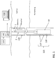
- FIG. 1 is a cross-sectional illustration of a borehole 1 including an interferometer-based sensor system according to an embodiment of the invention.
- a borehole 1 penetrates the earth 3 including a formation 4.
- a set of tools 10 may be lowered into the borehole by a carrier 2.
- the carrier may be an armored wireline.
- the carrier 2 may be a drill string, and a drill would be included below the tools 10.
- Information from the sensors and measurement devices included in the set of tools 10 may be telemetered to the surface for processing by the surface processing system 130.
- the interferometer-based sensor system includes an optical fiber 110. As shown in FIG.
- the optical fiber 110 includes fiber Bragg gratings (FBGs) 117 and a reference reflector 118 that comprise an interferometer 115.
- the interferometer-based sensor system also provides a tunable laser (120).
- the tunable laser 120 is shown at the surface of the earth 3 in FIG. 1 .
- the polarization scrambler 140 that acts on the tunable laser 120 output before the optical network 145 transmits the signal to the interferometer 115 is discussed in detail with reference to FIG. 2 below.
- FIG. 2 is a block diagram of an OFDR network 200 including a polarization scrambler 140 according to an embodiment of the invention.
- the polarization scrambler 140 acts on the signal from the tunable laser 120 being sent to the interferometer 115.
- the output of the tunable laser 120 may itself have a different polarization state over time. However, this variation in the signal from the tunable laser 120 is not certain or predictable.
- the polarization scrambler 140 can be made to randomly vary the polarization state of the tunable laser 120 output over time before it reaches the interferometer.
- the possible polarization states achieved by the polarization scrambler 140 may be mapped over time and would indicate uniform sampling that could be represented by a Poincaré sphere, for example. Even though the tunable laser 120 changes polarization states over time, it would not achieve this uniform sampling of polarization states.
- the polarization scrambler 140 may change polarization state of the tunable laser 120 output in a predefined pattern.
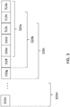
- FIG. 3 illustrates an exemplary processing scheme for the OFDR network 200 shown in FIG. 2 according to an embodiment of the invention.
- the polarization state of the tunable laser 120 output is randomly varied prior to each scan.
- the output 310 of the interferometer 115 for each scan is averaged over a number of scans.
- 5 outputs 310 (the result of 5 scans of the tunable laser 120 randomly varied in polarization state by the polarization scrambler 140) are averaged at a time in a sliding window fashion. That is, the first 5 outputs 310a - 310e are averaged as 320a, then the first scan 310a is dropped and the next scan 310f is included in the next average 320b.
- the sliding window average continues in this fashion.
- the average may be a weighted average such that larger amplitude interferometer 115 outputs 310 are weighted higher than lower amplitude outputs 310. Weighting may be based on other factors like signal-to-noise ratio, for example.
- the averaging increases the signal-to-noise ratio (SNR) of the interferometer 115 output 310.
- SNR signal-to-noise ratio
- the exemplary processing shown by FIG. 3 may be varied in one or more ways. For example, a different number of outputs 310 may be averaged at a time or a different weighting scheme may be used for the outputs 310 to provide the weighted average 320.
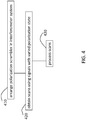
- FIG. 4 is a process flow diagram of an exemplary method 400 to obtain interferometer output using polarization scrambling according to embodiments of the invention.
- arranging the polarization scrambler 140 in the interferometer system may include, for example, arranging the polarization scrambler 140 between the tunable laser 120 and the interferometer 115 as shown in FIG. 2 for the exemplary OFDR network 200.
- Obtaining scans using signals with varied polarization state at block 420 includes the polarization scrambler 140 randomly or in a predefined pattern changing the polarization state of the tunable laser 120 output.
- Block 420 also includes receiving the resulting interferometer 115 output scans.
- Processing the scans at block 430 may include, for example, weighting and averaging a particular number of interferometer 115 output scans at a time in a sliding window fashion, as discussed with reference to FIG. 3 .
Landscapes
- Physics & Mathematics (AREA)
- General Physics & Mathematics (AREA)
- Health & Medical Sciences (AREA)
- Life Sciences & Earth Sciences (AREA)
- Chemical & Material Sciences (AREA)
- Analytical Chemistry (AREA)
- Biochemistry (AREA)
- General Health & Medical Sciences (AREA)
- Immunology (AREA)
- Pathology (AREA)
- Spectroscopy & Molecular Physics (AREA)
- Instruments For Measurement Of Length By Optical Means (AREA)
- Optical Communication System (AREA)
- Length Measuring Devices By Optical Means (AREA)
- Investigating Or Analysing Materials By Optical Means (AREA)
Description
- In downhole exploration and geologic resource recovery, the ability to obtain information about the conditions of the environment and the status of the equipment downhole can be helpful in making decisions. Optical frequency domain reflectometers (OFDR) are among the types of sensors used downhole. OFDR is an interferometer-based system that relies on the interference between signals generated or reflected by individual sources based on an optical signal. When the polarizations of the two signals are parallel to each other (0 degree angle between them), this provides maximum interference. However, when the two signals have orthogonal polarizations (90 degree angle between them), then there is no interference between the signals and, as a result, no signal from the interferometer. This results in noisy output from the OFDR system, which cannot know when the interferometer signal is null. Thus, an apparatus and method to ensure performance of the interferometer-based systems would be appreciated in the industry.
-
US 5104222 discloses a system and a method for minimizing polarisation induced phase noise in an interferometric sensor.US 2009/207416 discloses an apparatus for determining a surface characteristic using reflected light.US 2006/114471 discloses an interferometric optical analysis apparatus comprising a light source, an interferometer and a detection system, wherein unpolarised light is passed first through the interferometer then through a three-way polarisation splitter. - The present invention provides an interferometer-based system as claimed in
claim 1. The present invention also provides a method of obtaining and processing interferometer output scans as claimed in claim 7. According to one aspect of the invention, an interferometer-based sensor system includes a tunable laser configured to transmit a transmit signal; a polarization scrambler configured to produce a polarization state change on the transmit signal; an interferometer configured to provide an output scan based on the transmit signal with the polarization state change; and a processor configured to process the output scan. - According to another aspect of the invention, a method of obtaining and processing interferometer output scans includes arranging a polarization scrambler between a tunable laser and an interferometer; changing a polarization state of each signal from the tunable laser with the polarization scrambler to generate each polarization scrambled signal; receiving each of the output scans from the interferometer based on each of the polarization scrambled signals; and processing the output scans.
- Referring now to the drawings wherein like elements are numbered alike in the several Figures:
-
FIG. 1 is a cross-sectional illustration of a borehole including a distributed acoustic sensor system according to an embodiment of the invention; -
FIG. 2 is a block diagram of an OFDR network including a polarization scrambler according to an embodiment of the invention; -
FIG. 3 illustrates an exemplary processing scheme for the OFDR network shown inFIG. 2 according to an embodiment of the invention; and -
FIG. 4 is a process flow diagram of an exemplary method 400 to obtain interferometer output using polarization scrambling according to embodiments of the invention. - Any interferometer-based sensor system (e.g., optical frequency domain reflectometer (OFDR)) relies on the interference among signals generated or reflected by individual sources to generate the interferometer signal used to determine information of interest. Embodiments of the invention described herein ensure reliable interferometer signals for accurate measurements. While OFDR systems are used as exemplary interferometer-based systems for purposes of explanation, the scrambler and scrambling method detailed below applies, as well, to other interferometer-based systems.
-
FIG. 1 is a cross-sectional illustration of aborehole 1 including an interferometer-based sensor system according to an embodiment of the invention. Aborehole 1 penetrates theearth 3 including aformation 4. A set oftools 10 may be lowered into the borehole by acarrier 2. In embodiments of the invention, the carrier may be an armored wireline. In measure-while-drilling (MWD) embodiments, thecarrier 2 may be a drill string, and a drill would be included below thetools 10. Information from the sensors and measurement devices included in the set oftools 10 may be telemetered to the surface for processing by thesurface processing system 130. The interferometer-based sensor system includes anoptical fiber 110. As shown inFIG. 1 , theoptical fiber 110 includes fiber Bragg gratings (FBGs) 117 and areference reflector 118 that comprise aninterferometer 115. The interferometer-based sensor system also provides a tunable laser (120). Thetunable laser 120 is shown at the surface of theearth 3 inFIG. 1 . The polarization scrambler 140 that acts on thetunable laser 120 output before theoptical network 145 transmits the signal to theinterferometer 115 is discussed in detail with reference toFIG. 2 below. -
FIG. 2 is a block diagram of anOFDR network 200 including apolarization scrambler 140 according to an embodiment of the invention. The polarization scrambler 140 acts on the signal from thetunable laser 120 being sent to theinterferometer 115. By varying the polarization state of the signal input to theinterferometer 115, a higher percentage of non-null interferometer signals (signals not being perpendicular to each other) are ensured as interferometer output. The output of thetunable laser 120 may itself have a different polarization state over time. However, this variation in the signal from thetunable laser 120 is not certain or predictable. The polarization scrambler 140, unlike thetunable laser 120, can be made to randomly vary the polarization state of thetunable laser 120 output over time before it reaches the interferometer. The possible polarization states achieved by thepolarization scrambler 140 may be mapped over time and would indicate uniform sampling that could be represented by a Poincaré sphere, for example. Even though thetunable laser 120 changes polarization states over time, it would not achieve this uniform sampling of polarization states. In alternate embodiments, thepolarization scrambler 140 may change polarization state of thetunable laser 120 output in a predefined pattern. -
FIG. 3 illustrates an exemplary processing scheme for the OFDRnetwork 200 shown inFIG. 2 according to an embodiment of the invention. The polarization state of thetunable laser 120 output is randomly varied prior to each scan. The output 310 of theinterferometer 115 for each scan is averaged over a number of scans. In the embodiment shown inFIG. 3 , 5 outputs 310 (the result of 5 scans of thetunable laser 120 randomly varied in polarization state by the polarization scrambler 140) are averaged at a time in a sliding window fashion. That is, the first 5outputs 310a - 310e are averaged as 320a, then thefirst scan 310a is dropped and thenext scan 310f is included in thenext average 320b. The sliding window average continues in this fashion. The average may be a weighted average such thatlarger amplitude interferometer 115 outputs 310 are weighted higher than lower amplitude outputs 310. Weighting may be based on other factors like signal-to-noise ratio, for example. The averaging increases the signal-to-noise ratio (SNR) of theinterferometer 115 output 310. In alternate embodiments, the exemplary processing shown byFIG. 3 may be varied in one or more ways. For example, a different number of outputs 310 may be averaged at a time or a different weighting scheme may be used for the outputs 310 to provide the weighted average 320. -
FIG. 4 is a process flow diagram of an exemplary method 400 to obtain interferometer output using polarization scrambling according to embodiments of the invention. Atblock 410, arranging thepolarization scrambler 140 in the interferometer system may include, for example, arranging thepolarization scrambler 140 between thetunable laser 120 and theinterferometer 115 as shown inFIG. 2 for theexemplary OFDR network 200. Obtaining scans using signals with varied polarization state atblock 420 includes thepolarization scrambler 140 randomly or in a predefined pattern changing the polarization state of thetunable laser 120 output.Block 420 also includes receiving the resultinginterferometer 115 output scans. Processing the scans atblock 430 may include, for example, weighting and averaging a particular number ofinterferometer 115 output scans at a time in a sliding window fashion, as discussed with reference toFIG. 3 . - While one or more embodiments have been shown and described, modifications and substitutions may be made thereto without departing from the scope of the invention. Accordingly, it is to be understood that the present invention has been described by way of illustrations which is only limited according to the wording of the appended claims.
Claims (12)
- An interferometer-based sensor system, comprising:a tunable laser (120) configured to transmit a transmit signal;a polarization scrambler (140);an interferometer (117); anda processor (130)characterised in that the polarization scrambler (140) is configured to produce a polarization state change on the transmit signal prior to each scan;the interferometer (115) is configured to provide an output scan (310) based on the transmit signal with the polarization state change for each scan, wherein the interferometer (115) is comprised of one or more fiber Bragg gratings (FBGs) (117) and a reference reflector (118); and wherein the output scan (310) results from interference between a reflection signal from the reference reflector (118) with a reflection signal from one of the one or more FBGs (117); and in thatthe processor (130) is configured to process the output scan (310).
- The system according to claim 1, wherein the polarization state change is random, and, over a period of time, polarization states are uniform.
- The system according to claim 1, wherein the processor (130) processes a number of the output scans (310) at a time, the number being received over a period of time.
- The system according to claim 3, wherein the processor (130) performs a weighted average on the number of the output scans (310), each weighting being based on an amplitude of the respective output scan (310).
- The system according to claim 3, wherein the processor (130) performs a weighted average on the number of output scans (310), each weighting being based on a signal-to-noise ratio of the respective output scan (310).
- The system according to claim 3, wherein the processor (130) uses a sliding window to select the number of the output scans (310).
- A method of obtaining and processing interferometer output scans (310), the method comprising:arranging a polarization scrambler (140) between a tunable laser (120) and an interferometer (115);characterised in the interferometer (115) comprising one or more fibre Bragg gratings (FBGs) (117) and a reference reflector (118);and in the method further comprising changing a polarization state of each signal from the tunable laser (120) with the polarization scrambler to generate each polarization scrambled signal;receiving each of the output scans (310) from the interferometer (115) based on each of the polarization scrambled signals for each scan (310), each of the output scans (310) resulting from interference between a reflection signal from the reflection reflector (118) with a reflection signal from one of the one or more FBGS (117); andprocessing the output scans (310).
- The method according to claim 7, wherein the changing the polarization state includes generating a uniform sampling of polarization states over time.
- The method according to claim 7, wherein the processing the output scans (310) includes determining a weighted average of a number of the output scans (310).
- The method according to claim 9, wherein the determining the weighted average includes weighting each of the output scans (310) of the number of the output scans (310) based on an amplitude of the respective output scan (310).
- The method according to claim 9, wherein the determining the weighted average is done in a sliding window fashion with one of the number of the output scans (310) being different in each of the weighted averages.
- The method according to claim 9, wherein the determining the weighted average includes weighting each of the output scans (310) of the number of the output scans (310) based on a signal-to-noise ratio of the respective output scan (310).
Applications Claiming Priority (2)
| Application Number | Priority Date | Filing Date | Title |
|---|---|---|---|
| US13/707,979 US9291505B2 (en) | 2012-12-07 | 2012-12-07 | Polarization scrambling in interferometer systems |
| PCT/US2013/068068 WO2014088738A1 (en) | 2012-12-07 | 2013-11-01 | Polarization scrambling in interferometer systems |
Publications (4)
| Publication Number | Publication Date |
|---|---|
| EP2929377A1 EP2929377A1 (en) | 2015-10-14 |
| EP2929377A4 EP2929377A4 (en) | 2016-07-13 |
| EP2929377B1 true EP2929377B1 (en) | 2018-04-25 |
| EP2929377B8 EP2929377B8 (en) | 2018-06-06 |
Family
ID=50880637
Family Applications (1)
| Application Number | Title | Priority Date | Filing Date |
|---|---|---|---|
| EP13859792.7A Active EP2929377B8 (en) | 2012-12-07 | 2013-11-01 | Polarization scrambling in interferometer systems |
Country Status (8)
| Country | Link |
|---|---|
| US (1) | US9291505B2 (en) |
| EP (1) | EP2929377B8 (en) |
| AU (1) | AU2013356575B2 (en) |
| BR (1) | BR112015011943B1 (en) |
| CA (1) | CA2893085C (en) |
| DK (1) | DK2929377T3 (en) |
| NO (1) | NO3008053T3 (en) |
| WO (1) | WO2014088738A1 (en) |
Families Citing this family (2)
| Publication number | Priority date | Publication date | Assignee | Title |
|---|---|---|---|---|
| JP6226897B2 (en) * | 2015-02-20 | 2017-11-08 | アンリツ株式会社 | OFDR apparatus and method |
| US10677661B2 (en) | 2016-11-09 | 2020-06-09 | Northeastern University | Stop-start method in a microfluidic calorimeter |
Family Cites Families (18)
| Publication number | Priority date | Publication date | Assignee | Title |
|---|---|---|---|---|
| US5104222A (en) | 1990-09-18 | 1992-04-14 | The United States Of America As Represented By The Secretary Of The Navy | System and method for minimizing input polarization-induced phase noise in an interferometric fiber-optic sensor depolarized input light |
| NO322073B1 (en) | 1999-06-23 | 2006-08-07 | Optoplan As | Polarization Control Procedure |
| US6459487B1 (en) * | 2000-09-05 | 2002-10-01 | Gang Paul Chen | System and method for fabricating components of precise optical path length |
| US20030035120A1 (en) * | 2001-08-14 | 2003-02-20 | Myatt Christopher J. | Multiple-interferometer device for wavelength measuring and locking |
| AU2003212143A1 (en) * | 2002-03-14 | 2003-09-22 | University Of Ottawa | Dynamic polarization mode dispersion emulator |
| US7009691B2 (en) * | 2002-05-29 | 2006-03-07 | Agilent Technologies, Inc. | System and method for removing the relative phase uncertainty in device characterizations performed with a polarimeter |
| US20040264981A1 (en) * | 2003-06-25 | 2004-12-30 | Tyco Telecommunications (Us) Inc. | Wavelength monitoring and control system |
| US7088878B2 (en) * | 2003-08-27 | 2006-08-08 | Optoplan As | Method and apparatus for producing depolarized light |
| US7570851B2 (en) * | 2004-07-21 | 2009-08-04 | Purdue Research Foundation | Ultrashort photonic waveform measurement using quasi-phase-matched non-linear optics |
| US7426021B2 (en) * | 2004-11-29 | 2008-09-16 | Expo Electro- Optical Engineering Inc. | Interferometric optical analyzer and method for measuring the linear response of an optical component |
| JP4885212B2 (en) * | 2005-05-19 | 2012-02-29 | ザイゴ コーポレーション | Method and system for analyzing low coherence interferometer signals for information about thin film structures |
| US7282698B2 (en) | 2005-09-08 | 2007-10-16 | Baker Hughes Incorporated | System and method for monitoring a well |
| WO2007034802A1 (en) * | 2005-09-20 | 2007-03-29 | Sumitomo Electric Industries, Ltd. | Elasticity/viscosity measuring device |
| GB0611807D0 (en) * | 2006-06-14 | 2006-07-26 | Univ Huddersfield | A near common-path optical fibre interferometer for potentially fast on-line micro/nano scale surface measurement |
| US8285153B2 (en) * | 2007-02-27 | 2012-10-09 | Celight, Inc. | Single chip two-polarization quadrature synthesizer, analyser and optical communications system using the same |
| US8120781B2 (en) * | 2008-11-26 | 2012-02-21 | Zygo Corporation | Interferometric systems and methods featuring spectral analysis of unevenly sampled data |
| WO2010123698A1 (en) * | 2009-04-23 | 2010-10-28 | The Government Of The United States Of America, As Represented By The Secretary Of The Navy | Method and apparatus for characterizing a multilayered structure |
| WO2012068558A1 (en) | 2010-11-18 | 2012-05-24 | Redfen Integrated Optics, Inc. | Pulse labeling for high-bandwidth fiber-optic distributed acoustic sensing with reduced cross-talk |
-
2012
- 2012-12-07 US US13/707,979 patent/US9291505B2/en active Active
-
2013
- 2013-11-01 WO PCT/US2013/068068 patent/WO2014088738A1/en not_active Ceased
- 2013-11-01 DK DK13859792.7T patent/DK2929377T3/en active
- 2013-11-01 CA CA2893085A patent/CA2893085C/en active Active
- 2013-11-01 BR BR112015011943-3A patent/BR112015011943B1/en active IP Right Grant
- 2013-11-01 EP EP13859792.7A patent/EP2929377B8/en active Active
- 2013-11-01 AU AU2013356575A patent/AU2013356575B2/en active Active
-
2014
- 2014-06-13 NO NO14738957A patent/NO3008053T3/no unknown
Non-Patent Citations (1)
| Title |
|---|
| None * |
Also Published As
| Publication number | Publication date |
|---|---|
| BR112015011943B1 (en) | 2022-02-15 |
| EP2929377A1 (en) | 2015-10-14 |
| EP2929377A4 (en) | 2016-07-13 |
| US9291505B2 (en) | 2016-03-22 |
| US20140160483A1 (en) | 2014-06-12 |
| AU2013356575A1 (en) | 2015-05-28 |
| CA2893085C (en) | 2017-11-14 |
| AU2013356575B2 (en) | 2016-08-25 |
| BR112015011943A8 (en) | 2019-10-08 |
| WO2014088738A1 (en) | 2014-06-12 |
| EP2929377B8 (en) | 2018-06-06 |
| CA2893085A1 (en) | 2014-06-12 |
| NO3008053T3 (en) | 2018-08-18 |
| DK2929377T3 (en) | 2018-07-02 |
| BR112015011943A2 (en) | 2017-07-11 |
Similar Documents
| Publication | Publication Date | Title |
|---|---|---|
| CA2921023C (en) | Acoustic sensing system and method of acoustically monitoring a tool | |
| CA2934782C (en) | Systems and methods for multiple-code continuous-wave distributed acoustic sensing | |
| EP2596387B1 (en) | Distributed fiber optic sensor system with improved linearity | |
| US9784862B2 (en) | Distributed downhole acousting sensing | |
| US20180031413A1 (en) | Fiber optic distributed acoustic sensor omnidirectional antenna for use in downhole and marine applications | |
| CN106461495A (en) | Fibre optic distributed sensing | |
| EP3137735A1 (en) | Distributed acoustic sensing using low pulse repetition rates | |
| WO2017116383A1 (en) | Distributed optical sensing using compressive sampling | |
| CN114563026A (en) | Optical sensing method and device | |
| WO2016039928A1 (en) | Noise removal for distributed acoustic sensing data | |
| US11473421B2 (en) | Multi-frequency acoustic interrogation for azimuthal orientation of downhole tools | |
| Li et al. | Phase correction based SNR enhancement for distributed acoustic sensing with strong environmental background interference | |
| EP3134615A1 (en) | Attenuation correction for distributed temperature sensors using antistokes to rayleigh ratio | |
| CA2893085C (en) | Polarization scrambling in interferometer systems | |
| WO2020236179A1 (en) | De-spiking distributed acoustic sensor seismic profile |
Legal Events
| Date | Code | Title | Description |
|---|---|---|---|
| PUAI | Public reference made under article 153(3) epc to a published international application that has entered the european phase |
Free format text: ORIGINAL CODE: 0009012 |
|
| 17P | Request for examination filed |
Effective date: 20150701 |
|
| AK | Designated contracting states |
Kind code of ref document: A1 Designated state(s): AL AT BE BG CH CY CZ DE DK EE ES FI FR GB GR HR HU IE IS IT LI LT LU LV MC MK MT NL NO PL PT RO RS SE SI SK SM TR |
|
| AX | Request for extension of the european patent |
Extension state: BA ME |
|
| DAX | Request for extension of the european patent (deleted) | ||
| RA4 | Supplementary search report drawn up and despatched (corrected) |
Effective date: 20160610 |
|
| RIC1 | Information provided on ipc code assigned before grant |
Ipc: G01V 8/10 20060101AFI20160606BHEP Ipc: G01N 21/84 20060101ALI20160606BHEP Ipc: G01N 21/954 20060101ALI20160606BHEP Ipc: G01D 5/353 20060101ALI20160606BHEP |
|
| GRAP | Despatch of communication of intention to grant a patent |
Free format text: ORIGINAL CODE: EPIDOSNIGR1 |
|
| STAA | Information on the status of an ep patent application or granted ep patent |
Free format text: STATUS: GRANT OF PATENT IS INTENDED |
|
| INTG | Intention to grant announced |
Effective date: 20171109 |
|
| GRAA | (expected) grant |
Free format text: ORIGINAL CODE: 0009210 |
|
| GRAS | Grant fee paid |
Free format text: ORIGINAL CODE: EPIDOSNIGR3 |
|
| STAA | Information on the status of an ep patent application or granted ep patent |
Free format text: STATUS: THE PATENT HAS BEEN GRANTED |
|
| AK | Designated contracting states |
Kind code of ref document: B1 Designated state(s): AL AT BE BG CH CY CZ DE DK EE ES FI FR GB GR HR HU IE IS IT LI LT LU LV MC MK MT NL NO PL PT RO RS SE SI SK SM TR |
|
| REG | Reference to a national code |
Ref country code: GB Ref legal event code: FG4D |
|
| REG | Reference to a national code |
Ref country code: CH Ref legal event code: EP |
|
| REG | Reference to a national code |
Ref country code: AT Ref legal event code: REF Ref document number: 993507 Country of ref document: AT Kind code of ref document: T Effective date: 20180515 |
|
| REG | Reference to a national code |
Ref country code: IE Ref legal event code: FG4D |
|
| REG | Reference to a national code |
Ref country code: DE Ref legal event code: R096 Ref document number: 602013036681 Country of ref document: DE |
|
| RAP2 | Party data changed (patent owner data changed or rights of a patent transferred) |
Owner name: BAKER HUGHES, A GE COMPANY, LLC |
|
| REG | Reference to a national code |
Ref country code: DK Ref legal event code: T3 Effective date: 20180629 |
|
| REG | Reference to a national code |
Ref country code: NO Ref legal event code: T2 Effective date: 20180425 |
|
| REG | Reference to a national code |
Ref country code: NL Ref legal event code: MP Effective date: 20180425 |
|
| REG | Reference to a national code |
Ref country code: LT Ref legal event code: MG4D |
|
| PG25 | Lapsed in a contracting state [announced via postgrant information from national office to epo] |
Ref country code: NL Free format text: LAPSE BECAUSE OF FAILURE TO SUBMIT A TRANSLATION OF THE DESCRIPTION OR TO PAY THE FEE WITHIN THE PRESCRIBED TIME-LIMIT Effective date: 20180425 |
|
| PG25 | Lapsed in a contracting state [announced via postgrant information from national office to epo] |
Ref country code: ES Free format text: LAPSE BECAUSE OF FAILURE TO SUBMIT A TRANSLATION OF THE DESCRIPTION OR TO PAY THE FEE WITHIN THE PRESCRIBED TIME-LIMIT Effective date: 20180425 Ref country code: SE Free format text: LAPSE BECAUSE OF FAILURE TO SUBMIT A TRANSLATION OF THE DESCRIPTION OR TO PAY THE FEE WITHIN THE PRESCRIBED TIME-LIMIT Effective date: 20180425 Ref country code: BG Free format text: LAPSE BECAUSE OF FAILURE TO SUBMIT A TRANSLATION OF THE DESCRIPTION OR TO PAY THE FEE WITHIN THE PRESCRIBED TIME-LIMIT Effective date: 20180725 Ref country code: FI Free format text: LAPSE BECAUSE OF FAILURE TO SUBMIT A TRANSLATION OF THE DESCRIPTION OR TO PAY THE FEE WITHIN THE PRESCRIBED TIME-LIMIT Effective date: 20180425 Ref country code: PL Free format text: LAPSE BECAUSE OF FAILURE TO SUBMIT A TRANSLATION OF THE DESCRIPTION OR TO PAY THE FEE WITHIN THE PRESCRIBED TIME-LIMIT Effective date: 20180425 Ref country code: LT Free format text: LAPSE BECAUSE OF FAILURE TO SUBMIT A TRANSLATION OF THE DESCRIPTION OR TO PAY THE FEE WITHIN THE PRESCRIBED TIME-LIMIT Effective date: 20180425 |
|
| PG25 | Lapsed in a contracting state [announced via postgrant information from national office to epo] |
Ref country code: GR Free format text: LAPSE BECAUSE OF FAILURE TO SUBMIT A TRANSLATION OF THE DESCRIPTION OR TO PAY THE FEE WITHIN THE PRESCRIBED TIME-LIMIT Effective date: 20180726 Ref country code: HR Free format text: LAPSE BECAUSE OF FAILURE TO SUBMIT A TRANSLATION OF THE DESCRIPTION OR TO PAY THE FEE WITHIN THE PRESCRIBED TIME-LIMIT Effective date: 20180425 Ref country code: LV Free format text: LAPSE BECAUSE OF FAILURE TO SUBMIT A TRANSLATION OF THE DESCRIPTION OR TO PAY THE FEE WITHIN THE PRESCRIBED TIME-LIMIT Effective date: 20180425 Ref country code: RS Free format text: LAPSE BECAUSE OF FAILURE TO SUBMIT A TRANSLATION OF THE DESCRIPTION OR TO PAY THE FEE WITHIN THE PRESCRIBED TIME-LIMIT Effective date: 20180425 |
|
| REG | Reference to a national code |
Ref country code: AT Ref legal event code: MK05 Ref document number: 993507 Country of ref document: AT Kind code of ref document: T Effective date: 20180425 |
|
| PG25 | Lapsed in a contracting state [announced via postgrant information from national office to epo] |
Ref country code: PT Free format text: LAPSE BECAUSE OF FAILURE TO SUBMIT A TRANSLATION OF THE DESCRIPTION OR TO PAY THE FEE WITHIN THE PRESCRIBED TIME-LIMIT Effective date: 20180827 |
|
| REG | Reference to a national code |
Ref country code: DE Ref legal event code: R097 Ref document number: 602013036681 Country of ref document: DE |
|
| PG25 | Lapsed in a contracting state [announced via postgrant information from national office to epo] |
Ref country code: RO Free format text: LAPSE BECAUSE OF FAILURE TO SUBMIT A TRANSLATION OF THE DESCRIPTION OR TO PAY THE FEE WITHIN THE PRESCRIBED TIME-LIMIT Effective date: 20180425 Ref country code: CZ Free format text: LAPSE BECAUSE OF FAILURE TO SUBMIT A TRANSLATION OF THE DESCRIPTION OR TO PAY THE FEE WITHIN THE PRESCRIBED TIME-LIMIT Effective date: 20180425 Ref country code: EE Free format text: LAPSE BECAUSE OF FAILURE TO SUBMIT A TRANSLATION OF THE DESCRIPTION OR TO PAY THE FEE WITHIN THE PRESCRIBED TIME-LIMIT Effective date: 20180425 Ref country code: AT Free format text: LAPSE BECAUSE OF FAILURE TO SUBMIT A TRANSLATION OF THE DESCRIPTION OR TO PAY THE FEE WITHIN THE PRESCRIBED TIME-LIMIT Effective date: 20180425 Ref country code: SK Free format text: LAPSE BECAUSE OF FAILURE TO SUBMIT A TRANSLATION OF THE DESCRIPTION OR TO PAY THE FEE WITHIN THE PRESCRIBED TIME-LIMIT Effective date: 20180425 |
|
| PG25 | Lapsed in a contracting state [announced via postgrant information from national office to epo] |
Ref country code: IT Free format text: LAPSE BECAUSE OF FAILURE TO SUBMIT A TRANSLATION OF THE DESCRIPTION OR TO PAY THE FEE WITHIN THE PRESCRIBED TIME-LIMIT Effective date: 20180425 Ref country code: SM Free format text: LAPSE BECAUSE OF FAILURE TO SUBMIT A TRANSLATION OF THE DESCRIPTION OR TO PAY THE FEE WITHIN THE PRESCRIBED TIME-LIMIT Effective date: 20180425 |
|
| PLBE | No opposition filed within time limit |
Free format text: ORIGINAL CODE: 0009261 |
|
| STAA | Information on the status of an ep patent application or granted ep patent |
Free format text: STATUS: NO OPPOSITION FILED WITHIN TIME LIMIT |
|
| 26N | No opposition filed |
Effective date: 20190128 |
|
| PG25 | Lapsed in a contracting state [announced via postgrant information from national office to epo] |
Ref country code: SI Free format text: LAPSE BECAUSE OF FAILURE TO SUBMIT A TRANSLATION OF THE DESCRIPTION OR TO PAY THE FEE WITHIN THE PRESCRIBED TIME-LIMIT Effective date: 20180425 |
|
| REG | Reference to a national code |
Ref country code: DE Ref legal event code: R119 Ref document number: 602013036681 Country of ref document: DE |
|
| REG | Reference to a national code |
Ref country code: CH Ref legal event code: PL |
|
| GBPC | Gb: european patent ceased through non-payment of renewal fee |
Effective date: 20181101 |
|
| PG25 | Lapsed in a contracting state [announced via postgrant information from national office to epo] |
Ref country code: LU Free format text: LAPSE BECAUSE OF NON-PAYMENT OF DUE FEES Effective date: 20181101 Ref country code: MC Free format text: LAPSE BECAUSE OF FAILURE TO SUBMIT A TRANSLATION OF THE DESCRIPTION OR TO PAY THE FEE WITHIN THE PRESCRIBED TIME-LIMIT Effective date: 20180425 |
|
| REG | Reference to a national code |
Ref country code: BE Ref legal event code: MM Effective date: 20181130 |
|
| REG | Reference to a national code |
Ref country code: IE Ref legal event code: MM4A |
|
| PG25 | Lapsed in a contracting state [announced via postgrant information from national office to epo] |
Ref country code: LI Free format text: LAPSE BECAUSE OF NON-PAYMENT OF DUE FEES Effective date: 20181130 Ref country code: CH Free format text: LAPSE BECAUSE OF NON-PAYMENT OF DUE FEES Effective date: 20181130 |
|
| PG25 | Lapsed in a contracting state [announced via postgrant information from national office to epo] |
Ref country code: DE Free format text: LAPSE BECAUSE OF NON-PAYMENT OF DUE FEES Effective date: 20190601 Ref country code: IE Free format text: LAPSE BECAUSE OF NON-PAYMENT OF DUE FEES Effective date: 20181101 Ref country code: FR Free format text: LAPSE BECAUSE OF NON-PAYMENT OF DUE FEES Effective date: 20181130 |
|
| PG25 | Lapsed in a contracting state [announced via postgrant information from national office to epo] |
Ref country code: AL Free format text: LAPSE BECAUSE OF FAILURE TO SUBMIT A TRANSLATION OF THE DESCRIPTION OR TO PAY THE FEE WITHIN THE PRESCRIBED TIME-LIMIT Effective date: 20180425 Ref country code: BE Free format text: LAPSE BECAUSE OF NON-PAYMENT OF DUE FEES Effective date: 20181130 |
|
| PG25 | Lapsed in a contracting state [announced via postgrant information from national office to epo] |
Ref country code: GB Free format text: LAPSE BECAUSE OF NON-PAYMENT OF DUE FEES Effective date: 20181101 |
|
| PG25 | Lapsed in a contracting state [announced via postgrant information from national office to epo] |
Ref country code: MT Free format text: LAPSE BECAUSE OF NON-PAYMENT OF DUE FEES Effective date: 20181101 |
|
| PG25 | Lapsed in a contracting state [announced via postgrant information from national office to epo] |
Ref country code: TR Free format text: LAPSE BECAUSE OF FAILURE TO SUBMIT A TRANSLATION OF THE DESCRIPTION OR TO PAY THE FEE WITHIN THE PRESCRIBED TIME-LIMIT Effective date: 20180425 |
|
| PG25 | Lapsed in a contracting state [announced via postgrant information from national office to epo] |
Ref country code: CY Free format text: LAPSE BECAUSE OF FAILURE TO SUBMIT A TRANSLATION OF THE DESCRIPTION OR TO PAY THE FEE WITHIN THE PRESCRIBED TIME-LIMIT Effective date: 20180425 Ref country code: MK Free format text: LAPSE BECAUSE OF NON-PAYMENT OF DUE FEES Effective date: 20180425 Ref country code: HU Free format text: LAPSE BECAUSE OF FAILURE TO SUBMIT A TRANSLATION OF THE DESCRIPTION OR TO PAY THE FEE WITHIN THE PRESCRIBED TIME-LIMIT; INVALID AB INITIO Effective date: 20131101 |
|
| PG25 | Lapsed in a contracting state [announced via postgrant information from national office to epo] |
Ref country code: IS Free format text: LAPSE BECAUSE OF FAILURE TO SUBMIT A TRANSLATION OF THE DESCRIPTION OR TO PAY THE FEE WITHIN THE PRESCRIBED TIME-LIMIT Effective date: 20180825 |
|
| P01 | Opt-out of the competence of the unified patent court (upc) registered |
Effective date: 20230526 |
|
| PGFP | Annual fee paid to national office [announced via postgrant information from national office to epo] |
Ref country code: NO Payment date: 20251024 Year of fee payment: 13 |
|
| PGFP | Annual fee paid to national office [announced via postgrant information from national office to epo] |
Ref country code: DK Payment date: 20251022 Year of fee payment: 13 |