EP2929235B1 - Surveillance imaging system - Google Patents
Surveillance imaging system Download PDFInfo
- Publication number
- EP2929235B1 EP2929235B1 EP12889618.0A EP12889618A EP2929235B1 EP 2929235 B1 EP2929235 B1 EP 2929235B1 EP 12889618 A EP12889618 A EP 12889618A EP 2929235 B1 EP2929235 B1 EP 2929235B1
- Authority
- EP
- European Patent Office
- Prior art keywords
- microdiffractive
- diffusers
- diffuser
- illumination system
- illumination
- Prior art date
- Legal status (The legal status is an assumption and is not a legal conclusion. Google has not performed a legal analysis and makes no representation as to the accuracy of the status listed.)
- Active
Links
- 238000003384 imaging method Methods 0.000 title claims description 17
- 230000001427 coherent effect Effects 0.000 claims description 51
- 238000005286 illumination Methods 0.000 claims description 44
- 238000009826 distribution Methods 0.000 claims description 37
- 230000003287 optical effect Effects 0.000 claims description 29
- 230000000694 effects Effects 0.000 claims description 12
- 230000001965 increasing effect Effects 0.000 claims description 7
- 239000000758 substrate Substances 0.000 claims description 6
- 238000009792 diffusion process Methods 0.000 description 22
- 238000000034 method Methods 0.000 description 14
- 238000000265 homogenisation Methods 0.000 description 12
- 230000005855 radiation Effects 0.000 description 9
- 230000008901 benefit Effects 0.000 description 4
- 238000000926 separation method Methods 0.000 description 3
- 238000007493 shaping process Methods 0.000 description 3
- 238000003491 array Methods 0.000 description 2
- 239000000463 material Substances 0.000 description 2
- 238000002156 mixing Methods 0.000 description 2
- 239000002985 plastic film Substances 0.000 description 2
- 238000012935 Averaging Methods 0.000 description 1
- 230000005526 G1 to G0 transition Effects 0.000 description 1
- 238000013459 approach Methods 0.000 description 1
- 230000003247 decreasing effect Effects 0.000 description 1
- 230000002708 enhancing effect Effects 0.000 description 1
- 238000009499 grossing Methods 0.000 description 1
- 230000003760 hair shine Effects 0.000 description 1
- 238000007689 inspection Methods 0.000 description 1
- 238000009434 installation Methods 0.000 description 1
- 238000004519 manufacturing process Methods 0.000 description 1
- 238000012986 modification Methods 0.000 description 1
- 230000004048 modification Effects 0.000 description 1
- 230000009022 nonlinear effect Effects 0.000 description 1
- 230000000737 periodic effect Effects 0.000 description 1
- 229920003023 plastic Polymers 0.000 description 1
- 210000001525 retina Anatomy 0.000 description 1
- 230000002207 retinal effect Effects 0.000 description 1
- GOLXNESZZPUPJE-UHFFFAOYSA-N spiromesifen Chemical compound CC1=CC(C)=CC(C)=C1C(C(O1)=O)=C(OC(=O)CC(C)(C)C)C11CCCC1 GOLXNESZZPUPJE-UHFFFAOYSA-N 0.000 description 1
- 230000002123 temporal effect Effects 0.000 description 1
Images


Classifications
-
- G—PHYSICS
- G02—OPTICS
- G02B—OPTICAL ELEMENTS, SYSTEMS OR APPARATUS
- G02B27/00—Optical systems or apparatus not provided for by any of the groups G02B1/00 - G02B26/00, G02B30/00
- G02B27/48—Laser speckle optics
-
- F—MECHANICAL ENGINEERING; LIGHTING; HEATING; WEAPONS; BLASTING
- F21—LIGHTING
- F21S—NON-PORTABLE LIGHTING DEVICES; SYSTEMS THEREOF; VEHICLE LIGHTING DEVICES SPECIALLY ADAPTED FOR VEHICLE EXTERIORS
- F21S41/00—Illuminating devices specially adapted for vehicle exteriors, e.g. headlamps
- F21S41/10—Illuminating devices specially adapted for vehicle exteriors, e.g. headlamps characterised by the light source
- F21S41/14—Illuminating devices specially adapted for vehicle exteriors, e.g. headlamps characterised by the light source characterised by the type of light source
- F21S41/16—Laser light sources
-
- G—PHYSICS
- G02—OPTICS
- G02B—OPTICAL ELEMENTS, SYSTEMS OR APPARATUS
- G02B5/00—Optical elements other than lenses
- G02B5/02—Diffusing elements; Afocal elements
- G02B5/0205—Diffusing elements; Afocal elements characterised by the diffusing properties
- G02B5/021—Diffusing elements; Afocal elements characterised by the diffusing properties the diffusion taking place at the element's surface, e.g. by means of surface roughening or microprismatic structures
-
- G—PHYSICS
- G02—OPTICS
- G02B—OPTICAL ELEMENTS, SYSTEMS OR APPARATUS
- G02B5/00—Optical elements other than lenses
- G02B5/32—Holograms used as optical elements
-
- H—ELECTRICITY
- H04—ELECTRIC COMMUNICATION TECHNIQUE
- H04N—PICTORIAL COMMUNICATION, e.g. TELEVISION
- H04N7/00—Television systems
- H04N7/18—Closed-circuit television [CCTV] systems, i.e. systems in which the video signal is not broadcast
-
- G—PHYSICS
- G08—SIGNALLING
- G08B—SIGNALLING OR CALLING SYSTEMS; ORDER TELEGRAPHS; ALARM SYSTEMS
- G08B13/00—Burglar, theft or intruder alarms
- G08B13/18—Actuation by interference with heat, light, or radiation of shorter wavelength; Actuation by intruding sources of heat, light, or radiation of shorter wavelength
- G08B13/189—Actuation by interference with heat, light, or radiation of shorter wavelength; Actuation by intruding sources of heat, light, or radiation of shorter wavelength using passive radiation detection systems
- G08B13/194—Actuation by interference with heat, light, or radiation of shorter wavelength; Actuation by intruding sources of heat, light, or radiation of shorter wavelength using passive radiation detection systems using image scanning and comparing systems
- G08B13/196—Actuation by interference with heat, light, or radiation of shorter wavelength; Actuation by intruding sources of heat, light, or radiation of shorter wavelength using passive radiation detection systems using image scanning and comparing systems using television cameras
- G08B13/19617—Surveillance camera constructional details
- G08B13/19626—Surveillance camera constructional details optical details, e.g. lenses, mirrors or multiple lenses
-
- H—ELECTRICITY
- H01—ELECTRIC ELEMENTS
- H01S—DEVICES USING THE PROCESS OF LIGHT AMPLIFICATION BY STIMULATED EMISSION OF RADIATION [LASER] TO AMPLIFY OR GENERATE LIGHT; DEVICES USING STIMULATED EMISSION OF ELECTROMAGNETIC RADIATION IN WAVE RANGES OTHER THAN OPTICAL
- H01S5/00—Semiconductor lasers
- H01S5/005—Optical components external to the laser cavity, specially adapted therefor, e.g. for homogenisation or merging of the beams or for manipulating laser pulses, e.g. pulse shaping
Definitions
- This invention relates to a surveillance imaging system comprising an illumination system, and more specifically to phase homogenization of coherent light from illuminators used for surveillance imaging systems.
- LEDs light emitting diodes
- LDs now laser diodes
- LEDs are commonly used in surveillance illuminators, and often employ some method of optical diffuser to evenly distribute light on target, an optimal solution is not as simple when using laser diode (LD) illuminators.
- the current method of diffusion at the macroscopic level employs an array of small refractive lenses or lens-like patterns imprinted on thin transparent plastic sheets or films. Since LEDs emit a broad range of wavelengths combined from a multiplicity of single sources into overlapping beams, their randomized light can readily be diffused by common refractive diffusers to produce a homogenized distribution.
- Microdiffractive diffusers are optical elements comprising tiny lens-like surface structures measured at the nanometer scale which individually refract light in a randomized manner due to their non-periodic structures such that they collectively channel light into much smoother distributions than can be achieved with conventional lenses.
- the microdiffractive diffusers cause light to diverge, which smoothes and homogenizes the coherent light sources, providing uniform light without speckle or hotspots.
- the degree of smoothing achieved by the microdiffractive diffusers depends on the angle. For applications in which a greater degree of homogenization is required, large angle microdiffractive diffusers are utilized.
- microdiffractive diffusers play an important role in the phase homogenizer of coherent light illuminators used for surveillance imaging systems.
- the irradiance emitted by a laser diode is a single coherent source emitting at a much narrower wavelength band.
- Coherent light is susceptible to causing interference patterns when diffused or refracted which creates a speckle structure on the target which makes it more difficult to produce high quality images of illuminated objects with a surveillance video camera.
- Speckle noise is a field intensity pattern produced by the mutual interference of coherent beams that are subject to temporal and spatial fluctuations. To eliminate speckle noise, and to take advantage of the range boosting capabilities of laser diode based illuminators, a special means of homogenizing LD output should be employed.
- Existing methods for minimizing speckle noise include use of higher energy lasers whose non-linear effects can reduce source coherence, or inserting optical delay lines in beam paths with higher delay time than the laser coherence time.
- Another method is time averaging of many randomized speckle-patterns of an object image, through use of rapidly movable optical elements introducing non-stationary phase modulation of a laser beam.
- JP 2001 100621 A discloses a device for homogenizing light and its manufacturing method.
- An energy efficient illumination apparatus and a method for illuminating surfaces are known from US 2010/0103676 A1 .
- US 6,081,381 discloses an apparatus and a method for reducing spatial coherence and for improving uniformity of a light beam emitted from a coherent light source.
- Systems and methods for providing illumination of a specimen for inspection are known from US 2007/0052953 A1 .
- US 2008/0079904 A1 discloses display systems with spatial light modulation.
- a LD speckle homogenizer employing microdiffractive diffusion materials for long distance surveillance illuminators is needed for improved imaging outcomes.
- the following disclosure will describe such a solution.
- the surveillance imaging system comprising the illumination system of the present invention provides more efficient speckle homogenization of coherent light to be used in long distance surveillance illuminators, comprising a phase homogenizer with at least two microdiffractive diffusers aligned on an optical axis, which together thoroughly mix coherent light so that speckle noise has little effect on imaging of LD illuminated targets.
- True microdiffractive diffusers are efficient transmitters of light, but also are capable of refracting at highly selective beam angles, as well as creating asymmetric distributions.
- the phase homogenizer provides microdiffractiveally diffused illumination for long distance surveillance imaging.
- the microdiffractive diffusers are also effective at homogenizing light from an array of coherent light emitters such as an LD array.
- the invention can be summarized as a surveillance imaging system comprising a surveillance video camera and an illumination system comprising a coherent light emitter aligned with a light source raypath along an optical axis with at least two separated microdiffractive diffusers the surveillance video camera producing images of a target illuminated by the illumination system, the microdiffractive diffusers comprising holographically generated surfaces of microdiffractive structure that statistically tend to diffract light at selectable angles or distribution patterns, the microdiffractive diffusers disposed upon a substrate and separated from each other by a distance determined by wavelength phase and irradiance characteristics of the coherent light emitter and by refractive characteristics of at least two microdiffractive diffusers, followed by a homogenized exit raypath in order to produce a diffused pattern of illumination optimized for surveillance imaging of distances between 1 meter to more than 1000 meters, with a lens aligned on the optical axis and situated between a first diffuser of the at least two separated microdiffractive diffusers and
- the phase homogenizer comprises at least two microdiffractive diffusers aligned on an optical axis and a lens aligned on the optical axis and situated between the two diffusers.
- microdiffractive diffusers should be separated at a distance along the raypath such that coherent light emitted along the raypath is mixed and speckle noise effect is reduced on imaging of distant targets illuminated by the coherent light.
- the coherent light source can be a laser diode or an array of laser diodes.
- Using more than two separated microdiffractive diffusers can also be more effective in reducing speckle effect on the target, and in increasing the effective size of the light emitter from a perspective of an illuminated observer so that the diffused pattern of illumination is of lesser areal intensity for retinal safety of illuminated target individuals.
- first microdiffractive diffuser is separated from a second microdiffractive diffuser by a distance in a range from approximately 2.5 centimeters to 10 centimeters.
- the most legible resolutions are achieved in the 7 to 9 centimeter subrange. Beyond that range, there is additional benefit, but it diminishes and approaches full illegibility at about 40.6 centimeters. Any separation beyond the optimal range of 7 to 9 centimeters has the disadvantage of having a longer physical embodiment of the surveillance equipment.
- microdiffractive diffuser with LDs can increase the effective size of the light source as seen from an illuminated observer.
- microdiffractive diffusers prevent damage to the human retina if directly observed. This feature can prevent safety hazards to human sight when LD illuminators are used in public spaces or on unintended targets.
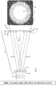
- FIG. 1 gives an overview of the basic elements of a surveillance illuminator employing a phase homogenizer 10.
- a coherent source 14 a laser diode array in this example, enters the phase homogenizer 10 by means of the source ray path 46 along the optical axis 42, and exits along the homogenized ray path 48, which then illuminates the target 28 with a homogenized distribution 30.
- Figure 2 illustrates how light from a random source 12 such as a light emitting diode array, projects a homogenized distribution 30 on the target 28, by means of a microdiffractive diffuser 16 on a substrate 18. Illumination through source points 20 (A, B, C) is diffused along a diffusion ray path 22, to their respective diffusion points 24, (A1, A2, B1, B2, C1, C2) on the distribution plane 26.
- a random source 12 such as a light emitting diode array
- Figure 3 illustrates how light from a coherent source 14 such as a laser diode, projects a speckled distribution 32 on the target 28, by means of a microdiffractive diffuser 16 on a substrate 18. Illumination through source points 20 (D, E, F) is diffused along a diffusion ray path 22, to their respective diffusion points 24, (D1, D2, E1, E2, F1, F2) on the distribution plane 26.
- a coherent source 14 such as a laser diode
- Figure 4 illustrates how light from a coherent source 14 can be made to project a homogenized distribution 30 on the target 28 by means of a microdiffractive diffuser 16 positioned at front and rear focal plane (34 & 38) of a refractive lens 36.
- the light diffused (22 & 24) from the source points 20 (D, E, F) at the front focal plane 34 is refracted by the lens 36 along the refracted ray path 40 to a second diffuser 16 at the rear focal plane 38.
- the output of the phase homogenizer 10 (lensed) follows the homogenized ray path 48 and projects a homogenized distribution 30 onto the target 28.
- Figure 5 illustrates the lensless phase homogenizer 44 (not part of the invention).
- Two microdiffractive diffusers 16 are placed at an appropriate distance apart to create the diffusion ray paths 22 illustrated.
- the resulting distribution on the target 28 is homogenized 30 at its center and speckled 32 at its periphery.
- LED arrays employ diffusers on top of beam-shaping optics and can be regarded as equivalent to an array of secondary light sources excited by a primary LED.
- An LED emits the combined radiation of many single-mode sources, each with very short coherence time.
- the resulting target 28 irradiance is an arithmetic sum of irradiances created by different parts of a microdiffractive diffuser 16.
- LED sources 12 generate randomized wavelengths that are seldom in phase, whereas an LD has a much longer coherence time, and so it can be put out of phase by diffraction or diffusion.
- Fig. 2 where the randomized source (LED) 12, is shown emitting non-coherent light through the microdiffractive diffuser 16, which spreads the random non-coherent light across the distribution plane 26, partly mixing it further.
- the resultant illumination on the target 28 presents a homogenized distribution 30.
- the target 28 irradiance of a coherent laser diode (LD) source 14 is defined by the vector sum of light waves sent to a target 28 by different parts of an LD or of a microdiffractive diffuser 16 inserted in its beam-path.
- a vector sum of light waves depends not only on irradiances created by different parts of a light source, like an arithmetic sum, but also on the phases of radiation coming from different parts of the source. Therefore, phase homogenization for a LD source 14 is a much more complicated problem than just intensity homogenization for an LED source 12.
- a coherent source (LD) 14 emits waves which are in phase with each other, then pass through the microdiffractive diffuser 16, and arrive at the same diffusion points 24 on the distribution plane 26 as does a randomized source 12. But unlike light from a non-coherent random source 12, light from a coherent source 14 constructively interferes (phases add) or destructively interferes (phases cancel) at its diffusion points 24. Depending on whether the wavelength phases of two intersecting diffusion ray paths 22 may be added together or cancel each other out, any given diffusion point 24 may present an island of double brightness or complete darkness, respectively.
- the speckled distribution 32 illustrated in Fig. 3 is the result of these interference patterns of diffused coherent light 14.
- homogenization will be defined as an optical energy distribution free of speckle noise over a specifically delimited area of illumination.
- microdiffractive diffuser used in this invention is necessary.
- a diffuser comprised of a holographically generated surface of microdiffractive structure that statistically tends to diffract light at a selectable angle or distribution pattern.
- Microdiffractive diffraction has a rough equivalence to macro-scale diffusion, but performs with greater optical efficiency and control over its light shaping properties.
- microdiffractive diffusers do not require precise alignment of discrete point sources to transmit maximum illuminance, as when an array of laser diodes projects a light manifold through a microdiffractive diffuser16.
- FIG 4 illustrates the preferred embodiment of the phase homogenizer 10 which employs microdiffractive diffusers 16 positioned at the front focal plane 34 and rear focal plane 38 of a refractive lens 36.
- the diffusion ray paths 22 are the same as those illustrated in Figs. 2 & 3 , but have been shortened in this drawing to make room for the full embodiment.
- source points 20 D, E, F
- any points of illumination from the LD source 14 could be used to demonstrate how the phase homogenizer 10 removes speckle noise.
- the diffuser 16 splits the light into a cone bounded by two diffusion ray paths 22 which enter the refractive lens 36 at the D1 & D2 diffusion points 24. Notice how the lens 36 bends the LD light along the refracted ray paths 40 to illuminate the entire inside surface of the second diffuser 16. Diffracted light from source points 20 E & F are also refracted so as to illuminate the inside surface of the second diffuser 16 positioned at the rear focal plane 38 of the lens 36. By this means each point of source light 14 is spread by the first diffuser 16, then collimated by the lens 36 onto the second diffuser 16, which then spreads it towards the target 28 via the homogenized ray path 48.
- the phase homogenizer 10 uses each point (D) of coherent light 14 to create a beam (D1 to D2) that shines through the second diffuser 16. Since there are theoretically an infinite number of source points 20, there are an infinite number of generated beams that wash through the second diffuser 16, and by this means coherent light 14 is randomized and diffusive speckle noise is removed.
- Any coherent light 16 from any source point 20 at the front focal plane 34 is in phase, and by passing through the phase homogenizer 10, is fully randomized, and therefore projects LD illumination on target 28 that is fully homogenized as defined above.
- Proven optical principles demonstrate that the optical energy distribution in a lens' rear focal plane 38 is a Fourier transform of the optical energy distribution in its front focal plane 34. Under such a transform the optical wave phase variation in the RFP 38 is proportional to the square of the ray coordinates both in the FFP 34 and RFP 38. By this means, the phase distribution of coherent light in the RFP 38 is effectively homogenized.
- phase homogenizer examples include, but are not limited to the use of asymmetric diffusers.
- Asymmetric Phase Homogenization Referring to Fig. 4 -- by replacing the existing microdiffractive diffuser 16 which creates symmetrical diffusion at the rear focal plane 38, with a microdiffractive diffuser 16 that creates an asymmetrical diffusion pattern, a directional distribution is possible.
- Directional or asymmetric diffusers have a surface comprised of a microdiffractive structure that statistically tends to refract light at a different angle in a horizontal plane than in a vertical plane.
- Asymmetric diffusion creates a Gaussian distribution which sends more light where it needs to be, onto targets 28 that are predominantly along the horizontal plane.
- the distribution created by a lens 36 and two diffusers 16 pressed together and placed after the lens 36 is similar to the distribution created by the same lens 36 and a single diffuser 16 with doubled diffusion angle, in place of these two diffusers 16.
- homogenization increases as the distance between the diffusers 16 is increased. At some distance the majority of speckle disappears and the distribution becomes homogenized 30.
- a similar result can be achieved just with two diffusers 16 without a lens 36.
- a lensless phase homogenizer 44 is composed of two microdiffractive diffusers 16 separated by sufficient distance to project an area of homogenized distribution 30 on the target 28 centered around the optical axis 42, but which is also surrounded by a ring of speckle distribution 32. If the diffusers 16 are far enough apart, the overlapping areas of speckle admit a cone of uniform mixing around the optical axis 42, so that the interference of coherent light 14 is averaged in this region.
- path lengths become mismatched and phases become randomized.
- the air gap randomizes the coherence, which key to homogenizing coherent light.
- Prior art solutions use mirrors or gratings or multiple lenses to create the equivalent to an air gap, but two diffusers can do this partially, although two diffusers surrounding a lens is the optimal solution.
- microdiffractive diffusers 16 are not precisely at either focal plane of a lens 36, the method of phase homogenization is still possible, but the distribution is not as uniform. Even when the diffusers 16 are on the same side of the lens 36, or without a lens 36 at all, but separated by a distance large enough so that the light reaching the second diffuser 16, and the radiation from majority of points of the first diffuser 16 are mixed, this method still gives suitable phase homogenization.
- each point of the second diffuser receives radiation from each point of the first diffuser, as illustrated in Fig. 5 .
- This is not valid only for the narrow strip at the edge of the second diffuser. So the light intensity distribution existing at the first diffuser is effectively mixed at the central area of the second diffuser.
- the optical wave phase at the second diffuser changes uniformly. So the phase distribution of light at the second diffuser is also effectively mixed, except at the edge of the second diffuser.
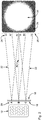
- row 1 shows the improvement in reading the license plate alphanumers from non-coherent illumination (on the left) to direct multimode laser diode (LD) light (in the middle), and the continued improvement (on the right) upon adding a diffuser just past (1 millimeter) the laser diode.
- Row 2 illustrates the improvement upon using 2 diffusers (left) and 3 diffusers (right), each 10 degrees, separated by 7 centimeters, with the main license plate alphanumerics clearly visible, and even the text of the jurisdiction of the plate coming into legibility.
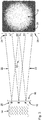
- Row 3 shows the effect of a single diffuser before the lens (left), after the lens (center), and with a diffuser before the lens and a second diffuser after (right).
- Row 4 shows the effect is achieved even if the second diffuser is different than the first, e.g. 10 degrees and 30 degrees (middle) and 10 degrees and 60 degrees (right).
- Row 5 shows the improving effect when the separation of two diffusers is increased from 2 centimeters (left) to 4 centimeters (center) to 10 centimeters (right).
- Row 6 shows continuing improvement at 12 centimeters of separation ("gap" in the drawing's labels), but negligible extra improvement from increasing beyond that to 15 centimeters (center) or 20 centimeters (right). There is essentially no improvement in resolution from additionally increasing the gap further, as shown in Row 7, to 25, 30, or 35 centimeters.
- the use of two separated diffusers in sequence introduces a new system quality not achievable with a single diffuser. It allows suppressing the FOI non-uniformity caused by light diffraction on microdiffractive diffusers 16 and by a laser modal structure.
- the method of homogenizing speckle by two separated microdiffractive diffusers 16 does not fall into the categories of eliminating speckle noise described elsewhere.
- the illuminance distribution created by a laser depends both on intensity and phase of all radiation parts, coming to a particular target point from different points of primary (laser itself) or secondary (diffuser surface) light sources.
- an LD can be used with a simplest optical beam shaping system comprising just two microdiffractive diffusers separated by a a distance determined by the wavelength phase and irradiance characteristics of the LD and by the refractive characteristics of the microdiffractive diffusers, without a lens. This is possible with the use of low divergence laser beams.
- FOI of such a system is a square root of sum of squares of diffusive angles of both diffusers.
- FOI For narrower FOI a simplest lens should be added and two small angle microdiffractive diffusers should be placed near its front and rear focal planes, with the LD manifold placed close to the first microdiffractive diffuser.
- FOI is defined by the diffusion angle of a second diffuser only, which can be different in vertical and horizontal planes to match the field of view of a camera used with the illuminator.
- Another embodiment includes the use of multiple element objectives (multiple lens combinations) in place of a single refractive lens between microdiffractive diffusers.
- the diffusers would be located at the front and rear focal planes of the resultant of the combined lenses.
- One application of the use of a multiple element objective would be to create a variable beam pattern with all the described properties of the preferred embodiment by moving the elements in the objective.
- phase homogenizer is primarily used for enhancing surveillance illumination for improved imaging.
- Other uses may include, but are not limited to the use of this invention in displays and light screens, projection systems, flat panel TVs, computer monitors, palm-held displays, barcode scanning, flashlights, lamps, microscope, fiber-optics, and LED illumination, laser, LD and CCFL homogeneity and beam shapers, optical sensing, bio-medical instrumentation, architectural, office and in-house lighting, automotive lighting, signs, posters and cell phone displays.
Description
- This invention relates to a surveillance imaging system comprising an illumination system, and more specifically to phase homogenization of coherent light from illuminators used for surveillance imaging systems.
- Surveillance imaging requires sufficient and evenly distributed on-scene illumination for adequate and timely target recognition. As distance to target increases, so must the range of effective illumination sources. Heavy, fragile, power-hungry, long-range filament bulb illuminators have been surpassed by more effective and power efficient arrays of light emitting diodes (LEDs) and now laser diodes (LDs).
- While LEDs are commonly used in surveillance illuminators, and often employ some method of optical diffuser to evenly distribute light on target, an optimal solution is not as simple when using laser diode (LD) illuminators. The current method of diffusion at the macroscopic level employs an array of small refractive lenses or lens-like patterns imprinted on thin transparent plastic sheets or films. Since LEDs emit a broad range of wavelengths combined from a multiplicity of single sources into overlapping beams, their randomized light can readily be diffused by common refractive diffusers to produce a homogenized distribution.
- Microdiffractive diffusers are optical elements comprising tiny lens-like surface structures measured at the nanometer scale which individually refract light in a randomized manner due to their non-periodic structures such that they collectively channel light into much smoother distributions than can be achieved with conventional lenses. The microdiffractive diffusers cause light to diverge, which smoothes and homogenizes the coherent light sources, providing uniform light without speckle or hotspots. The degree of smoothing achieved by the microdiffractive diffusers depends on the angle. For applications in which a greater degree of homogenization is required, large angle microdiffractive diffusers are utilized.
- Microdiffractive diffusers can work with all types of light, but are particularly effective when a collimated light source. Color diffraction is eliminated and incoming light is channeled towards well defined areas. Microdiffractive diffusion angles are measured at FWHM and microdiffractive diffusers have an effective angular output (EAO) defined by the equation:

- When combined in the arrangement herein described, microdiffractive diffusers play an important role in the phase homogenizer of coherent light illuminators used for surveillance imaging systems.
- The irradiance emitted by a laser diode (LD) is a single coherent source emitting at a much narrower wavelength band. Coherent light is susceptible to causing interference patterns when diffused or refracted which creates a speckle structure on the target which makes it more difficult to produce high quality images of illuminated objects with a surveillance video camera. Speckle noise is a field intensity pattern produced by the mutual interference of coherent beams that are subject to temporal and spatial fluctuations. To eliminate speckle noise, and to take advantage of the range boosting capabilities of laser diode based illuminators, a special means of homogenizing LD output should be employed.
- Existing methods for minimizing speckle noise include use of higher energy lasers whose non-linear effects can reduce source coherence, or inserting optical delay lines in beam paths with higher delay time than the laser coherence time. Another method is time averaging of many randomized speckle-patterns of an object image, through use of rapidly movable optical elements introducing non-stationary phase modulation of a laser beam.
- Short range solutions for removing LD speckle have been employed in photocopiers, digital projectors and point-of-sale barcode readers by the use of single diffusers in front of a refracting lens, rotating diffusers, and diffusers tailored for each color (projection systems). But surveillance illuminators must be capable of projecting diffused light across a wide range of distances (1 to 1000 meters and beyond) in order to create a recognizable image for camera. For this reason a speckle homogenizer employed with LD illuminators must be highly efficient at long distances.
-
JP 2001 100621 A US 2010/0103676 A1 .US 6,081,381 discloses an apparatus and a method for reducing spatial coherence and for improving uniformity of a light beam emitted from a coherent light source. Systems and methods for providing illumination of a specimen for inspection are known fromUS 2007/0052953 A1 .US 2008/0079904 A1 discloses display systems with spatial light modulation. - A LD speckle homogenizer employing microdiffractive diffusion materials for long distance surveillance illuminators is needed for improved imaging outcomes. The following disclosure will describe such a solution.
- The surveillance imaging system comprising the illumination system of the present invention provides more efficient speckle homogenization of coherent light to be used in long distance surveillance illuminators, comprising a phase homogenizer with at least two microdiffractive diffusers aligned on an optical axis, which together thoroughly mix coherent light so that speckle noise has little effect on imaging of LD illuminated targets. True microdiffractive diffusers are efficient transmitters of light, but also are capable of refracting at highly selective beam angles, as well as creating asymmetric distributions. Unlike short range devices which project LD light through macroscopically diffused optics to produce images, the phase homogenizer provides microdiffractiveally diffused illumination for long distance surveillance imaging. The microdiffractive diffusers are also effective at homogenizing light from an array of coherent light emitters such as an LD array.
- The invention can be summarized as a surveillance imaging system comprising a surveillance video camera and an illumination system comprising a coherent light emitter aligned with a light source raypath along an optical axis with at least two separated microdiffractive diffusers the surveillance video camera producing images of a target illuminated by the illumination system, the microdiffractive diffusers comprising holographically generated surfaces of microdiffractive structure that statistically tend to diffract light at selectable angles or distribution patterns, the microdiffractive diffusers disposed upon a substrate and separated from each other by a distance determined by wavelength phase and irradiance characteristics of the coherent light emitter and by refractive characteristics of at least two microdiffractive diffusers, followed by a homogenized exit raypath in order to produce a diffused pattern of illumination optimized for surveillance imaging of distances between 1 meter to more than 1000 meters, with a lens aligned on the optical axis and situated between a first diffuser of the at least two separated microdiffractive diffusers and a second diffuser of the at least two separated microdiffrative diffusers, the illumination system is configured such that a central portion of a diffused pattern of illumination on the target is unspeckled, in which the first microdiffractive diffuser is located proximate along the optical axis to the coherent light emitter and is smaller in diameter than the second microdiffractive diffuser that is farther from the coherent light emitter.
- According to the invention, the phase homogenizer comprises at least two microdiffractive diffusers aligned on an optical axis and a lens aligned on the optical axis and situated between the two diffusers.
- The microdiffractive diffusers should be separated at a distance along the raypath such that coherent light emitted along the raypath is mixed and speckle noise effect is reduced on imaging of distant targets illuminated by the coherent light.
- The coherent light source can be a laser diode or an array of laser diodes.
- Using more than two separated microdiffractive diffusers can also be more effective in reducing speckle effect on the target, and in increasing the effective size of the light emitter from a perspective of an illuminated observer so that the diffused pattern of illumination is of lesser areal intensity for retinal safety of illuminated target individuals.
- The salutary effects are achieved if a first microdiffractive diffuser is separated from a second microdiffractive diffuser by a distance in a range from approximately 2.5 centimeters to 10 centimeters. The most legible resolutions are achieved in the 7 to 9 centimeter subrange. Beyond that range, there is additional benefit, but it diminishes and approaches full illegibility at about 40.6 centimeters. Any separation beyond the optimal range of 7 to 9 centimeters has the disadvantage of having a longer physical embodiment of the surveillance equipment.
- In addition to the advantages outlined above, the use of microdiffractive diffuser with LDs can increase the effective size of the light source as seen from an illuminated observer. By decreasing laser beam areal intensity, microdiffractive diffusers prevent damage to the human retina if directly observed. This feature can prevent safety hazards to human sight when LD illuminators are used in public spaces or on unintended targets.
-
-
Figure 1 is a side view showing the basic elements of Surveillance Illumination System including a Phase Homogenizer. -
Figure 2 is a side view of a Random Source (LED) illuminating a Microdiffractive Diffuser and projecting a Homogenized distribution. -
Figure 3 is a side view of a Coherent Source (LD) illuminating a Microdiffractive Diffuser and projecting a Speckled distribution. -
Figure 4 is a side view of a Coherent Source (LD) illuminating a Phase Homogenizer (Lensed) and projecting a homogenized distribution. -
Figure 5 is a side view of a Coherent Source (LD) illuminating a Phase Homogenizer (Lensless) and projecting a partially homogenized distribution. -
Figure 6 shows the effects of different embodiments of the invention in differing quality of resolution of licence plates being surveilled.. -
Figure 1 gives an overview of the basic elements of a surveillance illuminator employing aphase homogenizer 10. Light from acoherent source 14, a laser diode array in this example, enters thephase homogenizer 10 by means of thesource ray path 46 along theoptical axis 42, and exits along thehomogenized ray path 48, which then illuminates thetarget 28 with ahomogenized distribution 30. -
Figure 2 illustrates how light from arandom source 12 such as a light emitting diode array, projects ahomogenized distribution 30 on thetarget 28, by means of amicrodiffractive diffuser 16 on asubstrate 18. Illumination through source points 20 (A, B, C) is diffused along adiffusion ray path 22, to theirrespective diffusion points 24, (A1, A2, B1, B2, C1, C2) on thedistribution plane 26. -
Figure 3 illustrates how light from acoherent source 14 such as a laser diode, projects a speckleddistribution 32 on thetarget 28, by means of amicrodiffractive diffuser 16 on asubstrate 18. Illumination through source points 20 (D, E, F) is diffused along adiffusion ray path 22, to theirrespective diffusion points 24, (D1, D2, E1, E2, F1, F2) on thedistribution plane 26. -
Figure 4 illustrates how light from acoherent source 14 can be made to project ahomogenized distribution 30 on thetarget 28 by means of amicrodiffractive diffuser 16 positioned at front and rear focal plane (34 & 38) of arefractive lens 36. The light diffused (22 & 24) from the source points 20 (D, E, F) at the frontfocal plane 34 is refracted by thelens 36 along the refractedray path 40 to asecond diffuser 16 at the rearfocal plane 38. The output of the phase homogenizer 10 (lensed) follows thehomogenized ray path 48 and projects ahomogenized distribution 30 onto thetarget 28. -
Figure 5 illustrates the lensless phase homogenizer 44 (not part of the invention). Twomicrodiffractive diffusers 16 are placed at an appropriate distance apart to create thediffusion ray paths 22 illustrated. The resulting distribution on thetarget 28 is homogenized 30 at its center and speckled 32 at its periphery. - LED arrays employ diffusers on top of beam-shaping optics and can be regarded as equivalent to an array of secondary light sources excited by a primary LED. An LED emits the combined radiation of many single-mode sources, each with very short coherence time. The resulting
target 28 irradiance is an arithmetic sum of irradiances created by different parts of amicrodiffractive diffuser 16.LED sources 12 generate randomized wavelengths that are seldom in phase, whereas an LD has a much longer coherence time, and so it can be put out of phase by diffraction or diffusion. - The above is illustrated in
Fig. 2 , where the randomized source (LED) 12, is shown emitting non-coherent light through themicrodiffractive diffuser 16, which spreads the random non-coherent light across thedistribution plane 26, partly mixing it further. The resultant illumination on thetarget 28 presents ahomogenized distribution 30. - The
target 28 irradiance of a coherent laser diode (LD)source 14 is defined by the vector sum of light waves sent to atarget 28 by different parts of an LD or of amicrodiffractive diffuser 16 inserted in its beam-path. A vector sum of light waves depends not only on irradiances created by different parts of a light source, like an arithmetic sum, but also on the phases of radiation coming from different parts of the source. Therefore, phase homogenization for aLD source 14 is a much more complicated problem than just intensity homogenization for anLED source 12. - As illustrated in
Fig. 3 , a coherent source (LD) 14 emits waves which are in phase with each other, then pass through themicrodiffractive diffuser 16, and arrive at the same diffusion points 24 on thedistribution plane 26 as does a randomizedsource 12. But unlike light from a non-coherentrandom source 12, light from acoherent source 14 constructively interferes (phases add) or destructively interferes (phases cancel) at its diffusion points 24. Depending on whether the wavelength phases of two intersectingdiffusion ray paths 22 may be added together or cancel each other out, any givendiffusion point 24 may present an island of double brightness or complete darkness, respectively. Thespeckled distribution 32 illustrated inFig. 3 is the result of these interference patterns of diffusedcoherent light 14. - The following is a more detailed explanation of the nature of the speckle effect created by coherent emitters. As described by equation (1) below, a single-mode laser emits the smallest possible Entendu (product of the beam waist size 2R0 by its divergence 2θ0 sine):

Fig. 3 ) Generally, this effect is not apparent by observing light bulbs or LEDs because their multichromatic radiation changes every few picoseconds, so we see a homogenized illumination. However, laser radiation is coherent and a laser keeps its modal structure over time. If we look at a multi-mode LD emitting zone through a microscope, we see a series of single-mode speckles that appear similar to the straight line of "grains" observed along a p-n junction. - For the purposes of this disclosure, the term homogenization will be defined as an optical energy distribution free of speckle noise over a specifically delimited area of illumination.
- A brief note on the properties of the microdiffractive diffuser used in this invention is necessary. Incorporated into the surface of a plastic-like substrate is a diffuser comprised of a holographically generated surface of microdiffractive structure that statistically tends to diffract light at a selectable angle or distribution pattern. Microdiffractive diffraction has a rough equivalence to macro-scale diffusion, but performs with greater optical efficiency and control over its light shaping properties. In addition, microdiffractive diffusers do not require precise alignment of discrete point sources to transmit maximum illuminance, as when an array of laser diodes projects a light manifold through a microdiffractive diffuser16.
- The preferred embodiment of the phase homogenizer will now be described in further detail.
Figure 4 illustrates the preferred embodiment of thephase homogenizer 10 which employsmicrodiffractive diffusers 16 positioned at the frontfocal plane 34 and rearfocal plane 38 of arefractive lens 36. Thediffusion ray paths 22 are the same as those illustrated inFigs. 2 &3 , but have been shortened in this drawing to make room for the full embodiment. Note that source points 20 (D, E, F) are representative, and that any points of illumination from theLD source 14 could be used to demonstrate how thephase homogenizer 10 removes speckle noise. - From the
D source point 20 at the frontfocal plane 34, thediffuser 16 splits the light into a cone bounded by twodiffusion ray paths 22 which enter therefractive lens 36 at the D1 & D2 diffusion points 24. Notice how thelens 36 bends the LD light along the refractedray paths 40 to illuminate the entire inside surface of thesecond diffuser 16. Diffracted light from source points 20 E & F are also refracted so as to illuminate the inside surface of thesecond diffuser 16 positioned at the rearfocal plane 38 of thelens 36. By this means each point of source light 14 is spread by thefirst diffuser 16, then collimated by thelens 36 onto thesecond diffuser 16, which then spreads it towards thetarget 28 via thehomogenized ray path 48. Thephase homogenizer 10 uses each point (D) ofcoherent light 14 to create a beam (D1 to D2) that shines through thesecond diffuser 16. Since there are theoretically an infinite number of source points 20, there are an infinite number of generated beams that wash through thesecond diffuser 16, and by this meanscoherent light 14 is randomized and diffusive speckle noise is removed. - Any coherent light 16 from any
source point 20 at the frontfocal plane 34 is in phase, and by passing through thephase homogenizer 10, is fully randomized, and therefore projects LD illumination ontarget 28 that is fully homogenized as defined above. - Proven optical principles demonstrate that the optical energy distribution in a lens' rear
focal plane 38 is a Fourier transform of the optical energy distribution in its frontfocal plane 34. Under such a transform the optical wave phase variation in theRFP 38 is proportional to the square of the ray coordinates both in theFFP 34 andRFP 38. By this means, the phase distribution of coherent light in theRFP 38 is effectively homogenized. - Other embodiments of the phase homogenizer include, but are not limited to the use of asymmetric diffusers.
- Asymmetric Phase Homogenization:
Referring toFig. 4 -- by replacing the existingmicrodiffractive diffuser 16 which creates symmetrical diffusion at the rearfocal plane 38, with amicrodiffractive diffuser 16 that creates an asymmetrical diffusion pattern, a directional distribution is possible. Directional or asymmetric diffusers have a surface comprised of a microdiffractive structure that statistically tends to refract light at a different angle in a horizontal plane than in a vertical plane. Asymmetric diffusion creates a Gaussian distribution which sends more light where it needs to be, ontotargets 28 that are predominantly along the horizontal plane. - The distribution created by a
lens 36 and twodiffusers 16 pressed together and placed after thelens 36 is similar to the distribution created by thesame lens 36 and asingle diffuser 16 with doubled diffusion angle, in place of these twodiffusers 16. However, when we increase the distance between twodiffusers 16, homogenization increases as the distance between thediffusers 16 is increased. At some distance the majority of speckle disappears and the distribution becomes homogenized 30. A similar result can be achieved just with twodiffusers 16 without alens 36. - Lensless Phase Homogenization (not part of the invention) is shown in
Fig. 5 . Alensless phase homogenizer 44, is composed of twomicrodiffractive diffusers 16 separated by sufficient distance to project an area ofhomogenized distribution 30 on thetarget 28 centered around theoptical axis 42, but which is also surrounded by a ring ofspeckle distribution 32. If thediffusers 16 are far enough apart, the overlapping areas of speckle admit a cone of uniform mixing around theoptical axis 42, so that the interference ofcoherent light 14 is averaged in this region. When rays are recombining on other side of the air gap, between D and D1 for example, path lengths become mismatched and phases become randomized. The air gap randomizes the coherence, which key to homogenizing coherent light. Prior art solutions use mirrors or gratings or multiple lenses to create the equivalent to an air gap, but two diffusers can do this partially, although two diffusers surrounding a lens is the optimal solution. - Note that when
microdiffractive diffusers 16 are not precisely at either focal plane of alens 36, the method of phase homogenization is still possible, but the distribution is not as uniform. Even when thediffusers 16 are on the same side of thelens 36, or without alens 36 at all, but separated by a distance large enough so that the light reaching thesecond diffuser 16, and the radiation from majority of points of thefirst diffuser 16 are mixed, this method still gives suitable phase homogenization. - When the effective size of the first diffuser is much smaller than the area illuminated by the light dispersed by the first diffuser, each point of the second diffuser receives radiation from each point of the first diffuser, as illustrated in
Fig. 5 . This is not valid only for the narrow strip at the edge of the second diffuser. So the light intensity distribution existing at the first diffuser is effectively mixed at the central area of the second diffuser. The optical wave phase at the second diffuser changes uniformly. So the phase distribution of light at the second diffuser is also effectively mixed, except at the edge of the second diffuser. - Referring to
Figure 6 ,row 1 shows the improvement in reading the license plate alphanumers from non-coherent illumination (on the left) to direct multimode laser diode (LD) light (in the middle), and the continued improvement (on the right) upon adding a diffuser just past (1 millimeter) the laser diode.Row 2 illustrates the improvement upon using 2 diffusers (left) and 3 diffusers (right), each 10 degrees, separated by 7 centimeters, with the main license plate alphanumerics clearly visible, and even the text of the jurisdiction of the plate coming into legibility.Row 3 shows the effect of a single diffuser before the lens (left), after the lens (center), and with a diffuser before the lens and a second diffuser after (right).Row 4 shows the effect is achieved even if the second diffuser is different than the first, e.g. 10 degrees and 30 degrees (middle) and 10 degrees and 60 degrees (right).Row 5 shows the improving effect when the separation of two diffusers is increased from 2 centimeters (left) to 4 centimeters (center) to 10 centimeters (right).Row 6 shows continuing improvement at 12 centimeters of separation ("gap" in the drawing's labels), but negligible extra improvement from increasing beyond that to 15 centimeters (center) or 20 centimeters (right). There is essentially no improvement in resolution from additionally increasing the gap further, as shown inRow 7, to 25, 30, or 35 centimeters. - The use of two separated diffusers in sequence introduces a new system quality not achievable with a single diffuser. It allows suppressing the FOI non-uniformity caused by light diffraction on
microdiffractive diffusers 16 and by a laser modal structure. The method of homogenizing speckle by two separatedmicrodiffractive diffusers 16 does not fall into the categories of eliminating speckle noise described elsewhere. The illuminance distribution created by a laser depends both on intensity and phase of all radiation parts, coming to a particular target point from different points of primary (laser itself) or secondary (diffuser surface) light sources. - Other embodiments are not ruled out or similar methods leading to the same result.
- For applications requiring moderate homogenization an LD can be used with a simplest optical beam shaping system comprising just two microdiffractive diffusers separated by a a distance determined by the wavelength phase and irradiance characteristics of the LD and by the refractive characteristics of the microdiffractive diffusers, without a lens. This is possible with the use of low divergence laser beams. FOI of such a system is a square root of sum of squares of diffusive angles of both diffusers.
- For narrower FOI a simplest lens should be added and two small angle microdiffractive diffusers should be placed near its front and rear focal planes, with the LD manifold placed close to the first microdiffractive diffuser. In this case the FOI is defined by the diffusion angle of a second diffuser only, which can be different in vertical and horizontal planes to match the field of view of a camera used with the illuminator.
- Another embodiment includes the use of multiple element objectives (multiple lens combinations) in place of a single refractive lens between microdiffractive diffusers. The diffusers would be located at the front and rear focal planes of the resultant of the combined lenses. One application of the use of a multiple element objective would be to create a variable beam pattern with all the described properties of the preferred embodiment by moving the elements in the objective.
- Other advantages of using the novel device over other methods or devices is described herein. A phase homogenizer is primarily used for enhancing surveillance illumination for improved imaging. Other uses may include, but are not limited to the use of this invention in displays and light screens, projection systems, flat panel TVs, computer monitors, palm-held displays, barcode scanning, flashlights, lamps, microscope, fiber-optics, and LED illumination, laser, LD and CCFL homogeneity and beam shapers, optical sensing, bio-medical instrumentation, architectural, office and in-house lighting, automotive lighting, signs, posters and cell phone displays.
- The foregoing description of the preferred apparatus and method of installation should be considered as illustrative only, and not limiting. Other forming techniques and other materials may be employed towards similar ends. Various changes and modifications will occur to those skilled in the art, without departing from the true scope of the invention as defined in the above disclosure, and the following general claims.
Claims (10)
- A surveillance imaging system comprising a surveillance video camera and an illumination system comprising a coherent light emitter (14) aligned with a light source raypath (46) along an optical axis (42) with at least two separated microdiffractive diffusers (16), the surveillance video camera producing images of a target (28) illuminated by the illumination system, the microdiffractive diffusers (16) comprising holographically generated surfaces of microdiffractive structure that statistically tend to diffract light at selectable angles or distribution patterns, the microdiffractive diffusers (16) disposed upon a substrate (18) and separated from each other by a distance determined by wavelength phase and irradiance characteristics of the coherent light emitter and by refractive characteristics of at least two microdiffractive diffusers (16), followed by a homogenized exit raypath (48) in order to produce a diffused pattern of illumination optimized for surveillance imaging of distances between 1 meter to more than 1000 meters, with a lens (36) aligned on the optical axis (42) and situated between a first diffuser of the at least two separated microdiffractive diffusers (16) and a second diffuser of the at least two separated microdiffrative diffusers (16), the illumination system is configured such that a central portion of a diffused pattern of illumination on the target (28) is unspeckled, in which the first microdiffractive diffuser (16) is located proximate along the optical axis (42) to the coherent light emitter (14) and is smaller in diameter than the second microdiffractive diffuser (16) that is farther from the coherent light emitter (14).
- The illumination system of Claim 1, in which the microdiffractive diffusers are separated at a distance along the raypath such that coherent light emitted along the raypath is mixed and speckle noise effect is reduced on imaging of distant targets (28) illuminated by the coherent light.
- The illumination system of Claim 1, in which the coherent light emitter comprises at least one laser diode.
- The illumination system of claim 1, in which the coherent light emitter comprises a laser diode array.
- The illumination system of claim 1, in which the illumination system is configured such that an aspect ratio of a diffused pattern of illumination is larger in a horizontal aspect than in a vertical aspect.
- The illumination system of claim 1, in which multiple microdiffractive diffusers are inserted and separated in the raypath such that the effective size of the light emitter from a perspective of an illuminated observer is increased and a diffused pattern of illumination is of lesser areal intensity.
- The illumination system of claim 1, in which the microdiffractive diffusers (16) are incorporated into the surface of the substrate (18).
- The illumination system of claim 1, in which two microdiffractive diffusers (16) are positioned to form at least two focal planes (34, 38), namely a front focal plane (34) and a rear focal plane (38), on either side of at least one optical element, both the front focal plane (34) and the rear focal planes (38) being perpendicular to the optical axis (42).
- The illumination system of claim 1, in which the first microdiffractive diffuser (16) is separated from the second microdiffractive diffuser (16) by a distance in a range from 4 centimeters to 35 centimeters.
- The illumination system of Claim 1, in which:a) the microdiffractive diffusers (16) are separated at a distance along the raypath such that coherent light emitted along the raypath is mixed and speckle noise effect is reduced on imaging of distant targets (28) illuminated by the coherent light;b) the coherent light emitter comprises a laser diode array;c) an aspect ratio of a diffused pattern of illumination is larger in a horizontal aspect than in a vertical aspect;d) multiple microdiffractive diffusers (16) are inserted and separated in the raypath such that the effective size of the light emitter from a perspective of an illuminated observer is increased and a diffused pattern of illumination is of lesser areal intensity.e) the microdiffractive diffusers (16) are positioned to form at least two focal planes (34, 38), namely a front focal plane (34) and a rear focal plane (38), on either side of at least one optical element, both the front focal plane (34) and the rear focal planes (38) being perpendicular to the optical axis (42);f) the first microdiffractive diffuser (16) is separated from the second microdiffractive diffuser (16) by a distance in a range from 10 to 15 centimeters.
Applications Claiming Priority (1)
| Application Number | Priority Date | Filing Date | Title |
|---|---|---|---|
| PCT/CA2012/050878 WO2014085895A1 (en) | 2012-12-07 | 2012-12-07 | Anti-speckle system for coherent illumination system |
Publications (3)
| Publication Number | Publication Date |
|---|---|
| EP2929235A1 EP2929235A1 (en) | 2015-10-14 |
| EP2929235A4 EP2929235A4 (en) | 2016-08-03 |
| EP2929235B1 true EP2929235B1 (en) | 2019-05-15 |
Family
ID=50882692
Family Applications (1)
| Application Number | Title | Priority Date | Filing Date |
|---|---|---|---|
| EP12889618.0A Active EP2929235B1 (en) | 2012-12-07 | 2012-12-07 | Surveillance imaging system |
Country Status (3)
| Country | Link |
|---|---|
| US (1) | US20150309326A1 (en) |
| EP (1) | EP2929235B1 (en) |
| WO (1) | WO2014085895A1 (en) |
Families Citing this family (4)
| Publication number | Priority date | Publication date | Assignee | Title |
|---|---|---|---|---|
| JP6471424B2 (en) * | 2013-11-13 | 2019-02-20 | セイコーエプソン株式会社 | projector |
| CN107076391B (en) * | 2014-11-07 | 2021-08-17 | 大日本印刷株式会社 | Lighting device |
| WO2017156545A1 (en) | 2016-03-11 | 2017-09-14 | The Regents Of The University Of California | Tunable, flexible and stretchable adhesive-integrated antenna |
| CN108825448B (en) * | 2018-06-25 | 2019-12-24 | 江苏金风科技有限公司 | Detection method and detection system for static deformation |
Family Cites Families (17)
| Publication number | Priority date | Publication date | Assignee | Title |
|---|---|---|---|---|
| US4368979A (en) * | 1980-05-22 | 1983-01-18 | Siemens Corporation | Automobile identification system |
| CA2168107C (en) * | 1993-07-27 | 2001-02-13 | Joel Petersen | Light source destructuring and shaping device |
| US20080147253A1 (en) * | 1997-10-22 | 2008-06-19 | Intelligent Technologies International, Inc. | Vehicular Anticipatory Sensor System |
| US6081381A (en) * | 1998-10-26 | 2000-06-27 | Polametrics, Inc. | Apparatus and method for reducing spatial coherence and for improving uniformity of a light beam emitted from a coherent light source |
| US6429429B1 (en) * | 2000-06-22 | 2002-08-06 | Ford Global Technologies, Inc. | Night vision system utilizing a diode laser illumination module and a method related thereto |
| CA2457653A1 (en) * | 2001-08-16 | 2003-02-27 | Optidtech Optical Identification Technologies Ltd. | Electro-optic reader for retro-reflective bar codes |
| ITMN20050049A1 (en) * | 2005-07-18 | 2007-01-19 | Balzanelli Sonia | VISUAL DEVICE FOR VEHICLES IN DIFFICULT CLIMATE-ENVIRONMENTAL CONDITIONS |
| US7304731B2 (en) * | 2005-09-02 | 2007-12-04 | Kla-Tencor Technologies Corp. | Systems and methods for providing illumination of a specimen for inspection |
| JP2010504596A (en) * | 2006-09-25 | 2010-02-12 | トニー・メイアー | Micro diffraction monitoring illumination system |
| US20080079904A1 (en) * | 2006-09-30 | 2008-04-03 | Texas Instruments Incorporated | Display systems with spatial light modulators |
| US20090213350A1 (en) * | 2008-02-22 | 2009-08-27 | Nikon Corporation | Coherence-reduction devices and methods for pulsed lasers |
| WO2009133111A1 (en) * | 2008-04-29 | 2009-11-05 | Optyka Limited | Optical system for speckle reduction |
| US8376585B2 (en) * | 2008-10-28 | 2013-02-19 | Raymond A. Noeth | Energy efficient illumination apparatus and method for illuminating surfaces |
| WO2010067282A1 (en) * | 2008-12-12 | 2010-06-17 | Koninklijke Philips Electronics N. V. | Lighting apparatus |
| US20110032587A1 (en) * | 2009-03-20 | 2011-02-10 | Absolute Imaging LLC | System and Method for Autostereoscopic Imaging |
| US8366281B2 (en) * | 2009-05-21 | 2013-02-05 | Eastman Kodak Company | Out-of-plane motion of speckle reduction element |
| EP3657235A1 (en) * | 2011-04-12 | 2020-05-27 | Barco N.V. | Laser projector with reduced speckle |
-
2012
- 2012-12-07 EP EP12889618.0A patent/EP2929235B1/en active Active
- 2012-12-07 US US14/650,028 patent/US20150309326A1/en not_active Abandoned
- 2012-12-07 WO PCT/CA2012/050878 patent/WO2014085895A1/en active Application Filing
Non-Patent Citations (1)
| Title |
|---|
| None * |
Also Published As
| Publication number | Publication date |
|---|---|
| EP2929235A4 (en) | 2016-08-03 |
| US20150309326A1 (en) | 2015-10-29 |
| EP2929235A1 (en) | 2015-10-14 |
| WO2014085895A1 (en) | 2014-06-12 |
Similar Documents
| Publication | Publication Date | Title |
|---|---|---|
| CN100355022C (en) | Illuminating method, exposing method, and device for therefor | |
| TWI572955B (en) | Unidirectional grating-based backlighting employing an angularly selective reflective layer | |
| US7972009B2 (en) | Projector and projection unit | |
| CN101238735B (en) | Image generation unit and method to use an image generation unit | |
| EP3118679B1 (en) | Illumination device | |
| US20070110386A1 (en) | Device having combined diffusing, collimating, and color mixing light control function | |
| US20150277137A1 (en) | Speckle free laser projection | |
| EP2929235B1 (en) | Surveillance imaging system | |
| KR20150030246A (en) | Efficient spatially modulated illumination system | |
| WO2006060096A1 (en) | Compact color illumination device | |
| CN101762959A (en) | Laser projection device and method for manufacturing a laser projection device | |
| EP1793263A1 (en) | Light intensity and/or colour distribution correcting element for an illumination system whose function is correlated to the incident light distribution | |
| US8786948B2 (en) | Apparatus for illuminating a reticle | |
| RU2632254C2 (en) | Lighting device | |
| WO2005084213A3 (en) | Light recycler and color display system including same | |
| CN113272686B (en) | Optical system and lighting device | |
| KR20220012159A (en) | Light Expander and Operating method including thereof | |
| KR20180006694A (en) | Backlight unit for head up display apparatus | |
| US10359692B2 (en) | Laser illumination system and method for eliminating laser speckle thereof | |
| US20190310411A1 (en) | Optical system with diffusers and honeycomb condensers | |
| JP7174920B2 (en) | Display device | |
| EP3943996A1 (en) | Beam expander and method of operating the same | |
| JP2014170034A (en) | Image display device | |
| CN112987476B (en) | Holographic speckle screen for projection display system | |
| JP2006114331A (en) | Illumination device |
Legal Events
| Date | Code | Title | Description |
|---|---|---|---|
| PUAI | Public reference made under article 153(3) epc to a published international application that has entered the european phase |
Free format text: ORIGINAL CODE: 0009012 |
|
| 17P | Request for examination filed |
Effective date: 20150707 |
|
| AK | Designated contracting states |
Kind code of ref document: A1 Designated state(s): AL AT BE BG CH CY CZ DE DK EE ES FI FR GB GR HR HU IE IS IT LI LT LU LV MC MK MT NL NO PL PT RO RS SE SI SK SM TR |
|
| AX | Request for extension of the european patent |
Extension state: BA ME |
|
| DAX | Request for extension of the european patent (deleted) | ||
| RA4 | Supplementary search report drawn up and despatched (corrected) |
Effective date: 20160701 |
|
| RIC1 | Information provided on ipc code assigned before grant |
Ipc: G08B 13/196 20060101ALI20160624BHEP Ipc: G02B 5/32 20060101ALI20160624BHEP Ipc: F21V 5/00 20150101AFI20160624BHEP Ipc: G08G 1/017 20060101ALI20160624BHEP Ipc: H01S 5/00 20060101ALI20160624BHEP Ipc: H04N 7/18 20060101ALI20160624BHEP Ipc: G02B 27/48 20060101ALI20160624BHEP Ipc: F21K 99/00 20160101ALI20160624BHEP Ipc: G02B 5/02 20060101ALI20160624BHEP |
|
| STAA | Information on the status of an ep patent application or granted ep patent |
Free format text: STATUS: EXAMINATION IS IN PROGRESS |
|
| 17Q | First examination report despatched |
Effective date: 20170413 |
|
| GRAP | Despatch of communication of intention to grant a patent |
Free format text: ORIGINAL CODE: EPIDOSNIGR1 |
|
| STAA | Information on the status of an ep patent application or granted ep patent |
Free format text: STATUS: GRANT OF PATENT IS INTENDED |
|
| INTG | Intention to grant announced |
Effective date: 20190111 |
|
| GRAS | Grant fee paid |
Free format text: ORIGINAL CODE: EPIDOSNIGR3 |
|
| GRAA | (expected) grant |
Free format text: ORIGINAL CODE: 0009210 |
|
| STAA | Information on the status of an ep patent application or granted ep patent |
Free format text: STATUS: THE PATENT HAS BEEN GRANTED |
|
| AK | Designated contracting states |
Kind code of ref document: B1 Designated state(s): AL AT BE BG CH CY CZ DE DK EE ES FI FR GB GR HR HU IE IS IT LI LT LU LV MC MK MT NL NO PL PT RO RS SE SI SK SM TR |
|
| REG | Reference to a national code |
Ref country code: CH Ref legal event code: EP |
|
| REG | Reference to a national code |
Ref country code: DE Ref legal event code: R096 Ref document number: 602012060260 Country of ref document: DE |
|
| REG | Reference to a national code |
Ref country code: IE Ref legal event code: FG4D |
|
| REG | Reference to a national code |
Ref country code: NL Ref legal event code: MP Effective date: 20190515 |
|
| REG | Reference to a national code |
Ref country code: LT Ref legal event code: MG4D |
|
| PG25 | Lapsed in a contracting state [announced via postgrant information from national office to epo] |
Ref country code: LT Free format text: LAPSE BECAUSE OF FAILURE TO SUBMIT A TRANSLATION OF THE DESCRIPTION OR TO PAY THE FEE WITHIN THE PRESCRIBED TIME-LIMIT Effective date: 20190515 Ref country code: NL Free format text: LAPSE BECAUSE OF FAILURE TO SUBMIT A TRANSLATION OF THE DESCRIPTION OR TO PAY THE FEE WITHIN THE PRESCRIBED TIME-LIMIT Effective date: 20190515 Ref country code: HR Free format text: LAPSE BECAUSE OF FAILURE TO SUBMIT A TRANSLATION OF THE DESCRIPTION OR TO PAY THE FEE WITHIN THE PRESCRIBED TIME-LIMIT Effective date: 20190515 Ref country code: SE Free format text: LAPSE BECAUSE OF FAILURE TO SUBMIT A TRANSLATION OF THE DESCRIPTION OR TO PAY THE FEE WITHIN THE PRESCRIBED TIME-LIMIT Effective date: 20190515 Ref country code: ES Free format text: LAPSE BECAUSE OF FAILURE TO SUBMIT A TRANSLATION OF THE DESCRIPTION OR TO PAY THE FEE WITHIN THE PRESCRIBED TIME-LIMIT Effective date: 20190515 Ref country code: NO Free format text: LAPSE BECAUSE OF FAILURE TO SUBMIT A TRANSLATION OF THE DESCRIPTION OR TO PAY THE FEE WITHIN THE PRESCRIBED TIME-LIMIT Effective date: 20190815 Ref country code: AL Free format text: LAPSE BECAUSE OF FAILURE TO SUBMIT A TRANSLATION OF THE DESCRIPTION OR TO PAY THE FEE WITHIN THE PRESCRIBED TIME-LIMIT Effective date: 20190515 Ref country code: PT Free format text: LAPSE BECAUSE OF FAILURE TO SUBMIT A TRANSLATION OF THE DESCRIPTION OR TO PAY THE FEE WITHIN THE PRESCRIBED TIME-LIMIT Effective date: 20190915 Ref country code: FI Free format text: LAPSE BECAUSE OF FAILURE TO SUBMIT A TRANSLATION OF THE DESCRIPTION OR TO PAY THE FEE WITHIN THE PRESCRIBED TIME-LIMIT Effective date: 20190515 |
|
| PG25 | Lapsed in a contracting state [announced via postgrant information from national office to epo] |
Ref country code: BG Free format text: LAPSE BECAUSE OF FAILURE TO SUBMIT A TRANSLATION OF THE DESCRIPTION OR TO PAY THE FEE WITHIN THE PRESCRIBED TIME-LIMIT Effective date: 20190815 Ref country code: GR Free format text: LAPSE BECAUSE OF FAILURE TO SUBMIT A TRANSLATION OF THE DESCRIPTION OR TO PAY THE FEE WITHIN THE PRESCRIBED TIME-LIMIT Effective date: 20190816 Ref country code: RS Free format text: LAPSE BECAUSE OF FAILURE TO SUBMIT A TRANSLATION OF THE DESCRIPTION OR TO PAY THE FEE WITHIN THE PRESCRIBED TIME-LIMIT Effective date: 20190515 Ref country code: LV Free format text: LAPSE BECAUSE OF FAILURE TO SUBMIT A TRANSLATION OF THE DESCRIPTION OR TO PAY THE FEE WITHIN THE PRESCRIBED TIME-LIMIT Effective date: 20190515 |
|
| REG | Reference to a national code |
Ref country code: AT Ref legal event code: MK05 Ref document number: 1133857 Country of ref document: AT Kind code of ref document: T Effective date: 20190515 |
|
| PG25 | Lapsed in a contracting state [announced via postgrant information from national office to epo] |
Ref country code: EE Free format text: LAPSE BECAUSE OF FAILURE TO SUBMIT A TRANSLATION OF THE DESCRIPTION OR TO PAY THE FEE WITHIN THE PRESCRIBED TIME-LIMIT Effective date: 20190515 Ref country code: DK Free format text: LAPSE BECAUSE OF FAILURE TO SUBMIT A TRANSLATION OF THE DESCRIPTION OR TO PAY THE FEE WITHIN THE PRESCRIBED TIME-LIMIT Effective date: 20190515 Ref country code: SK Free format text: LAPSE BECAUSE OF FAILURE TO SUBMIT A TRANSLATION OF THE DESCRIPTION OR TO PAY THE FEE WITHIN THE PRESCRIBED TIME-LIMIT Effective date: 20190515 Ref country code: CZ Free format text: LAPSE BECAUSE OF FAILURE TO SUBMIT A TRANSLATION OF THE DESCRIPTION OR TO PAY THE FEE WITHIN THE PRESCRIBED TIME-LIMIT Effective date: 20190515 Ref country code: RO Free format text: LAPSE BECAUSE OF FAILURE TO SUBMIT A TRANSLATION OF THE DESCRIPTION OR TO PAY THE FEE WITHIN THE PRESCRIBED TIME-LIMIT Effective date: 20190515 Ref country code: AT Free format text: LAPSE BECAUSE OF FAILURE TO SUBMIT A TRANSLATION OF THE DESCRIPTION OR TO PAY THE FEE WITHIN THE PRESCRIBED TIME-LIMIT Effective date: 20190515 |
|
| REG | Reference to a national code |
Ref country code: DE Ref legal event code: R097 Ref document number: 602012060260 Country of ref document: DE |
|
| PG25 | Lapsed in a contracting state [announced via postgrant information from national office to epo] |
Ref country code: IT Free format text: LAPSE BECAUSE OF FAILURE TO SUBMIT A TRANSLATION OF THE DESCRIPTION OR TO PAY THE FEE WITHIN THE PRESCRIBED TIME-LIMIT Effective date: 20190515 Ref country code: SM Free format text: LAPSE BECAUSE OF FAILURE TO SUBMIT A TRANSLATION OF THE DESCRIPTION OR TO PAY THE FEE WITHIN THE PRESCRIBED TIME-LIMIT Effective date: 20190515 |
|
| PLBE | No opposition filed within time limit |
Free format text: ORIGINAL CODE: 0009261 |
|
| STAA | Information on the status of an ep patent application or granted ep patent |
Free format text: STATUS: NO OPPOSITION FILED WITHIN TIME LIMIT |
|
| PG25 | Lapsed in a contracting state [announced via postgrant information from national office to epo] |
Ref country code: TR Free format text: LAPSE BECAUSE OF FAILURE TO SUBMIT A TRANSLATION OF THE DESCRIPTION OR TO PAY THE FEE WITHIN THE PRESCRIBED TIME-LIMIT Effective date: 20190515 |
|
| 26N | No opposition filed |
Effective date: 20200218 |
|
| PG25 | Lapsed in a contracting state [announced via postgrant information from national office to epo] |
Ref country code: PL Free format text: LAPSE BECAUSE OF FAILURE TO SUBMIT A TRANSLATION OF THE DESCRIPTION OR TO PAY THE FEE WITHIN THE PRESCRIBED TIME-LIMIT Effective date: 20190515 |
|
| PG25 | Lapsed in a contracting state [announced via postgrant information from national office to epo] |
Ref country code: SI Free format text: LAPSE BECAUSE OF FAILURE TO SUBMIT A TRANSLATION OF THE DESCRIPTION OR TO PAY THE FEE WITHIN THE PRESCRIBED TIME-LIMIT Effective date: 20190515 |
|
| REG | Reference to a national code |
Ref country code: CH Ref legal event code: PL |
|
| REG | Reference to a national code |
Ref country code: BE Ref legal event code: MM Effective date: 20191231 |
|
| PG25 | Lapsed in a contracting state [announced via postgrant information from national office to epo] |
Ref country code: MC Free format text: LAPSE BECAUSE OF FAILURE TO SUBMIT A TRANSLATION OF THE DESCRIPTION OR TO PAY THE FEE WITHIN THE PRESCRIBED TIME-LIMIT Effective date: 20190515 |
|
| PG25 | Lapsed in a contracting state [announced via postgrant information from national office to epo] |
Ref country code: LU Free format text: LAPSE BECAUSE OF NON-PAYMENT OF DUE FEES Effective date: 20191207 Ref country code: IE Free format text: LAPSE BECAUSE OF NON-PAYMENT OF DUE FEES Effective date: 20191207 Ref country code: FR Free format text: LAPSE BECAUSE OF NON-PAYMENT OF DUE FEES Effective date: 20191231 |
|
| PG25 | Lapsed in a contracting state [announced via postgrant information from national office to epo] |
Ref country code: CH Free format text: LAPSE BECAUSE OF NON-PAYMENT OF DUE FEES Effective date: 20191231 Ref country code: BE Free format text: LAPSE BECAUSE OF NON-PAYMENT OF DUE FEES Effective date: 20191231 Ref country code: LI Free format text: LAPSE BECAUSE OF NON-PAYMENT OF DUE FEES Effective date: 20191231 |
|
| PG25 | Lapsed in a contracting state [announced via postgrant information from national office to epo] |
Ref country code: CY Free format text: LAPSE BECAUSE OF FAILURE TO SUBMIT A TRANSLATION OF THE DESCRIPTION OR TO PAY THE FEE WITHIN THE PRESCRIBED TIME-LIMIT Effective date: 20190515 |
|
| PG25 | Lapsed in a contracting state [announced via postgrant information from national office to epo] |
Ref country code: IS Free format text: LAPSE BECAUSE OF FAILURE TO SUBMIT A TRANSLATION OF THE DESCRIPTION OR TO PAY THE FEE WITHIN THE PRESCRIBED TIME-LIMIT Effective date: 20190915 |
|
| PG25 | Lapsed in a contracting state [announced via postgrant information from national office to epo] |
Ref country code: HU Free format text: LAPSE BECAUSE OF FAILURE TO SUBMIT A TRANSLATION OF THE DESCRIPTION OR TO PAY THE FEE WITHIN THE PRESCRIBED TIME-LIMIT; INVALID AB INITIO Effective date: 20121207 Ref country code: MT Free format text: LAPSE BECAUSE OF FAILURE TO SUBMIT A TRANSLATION OF THE DESCRIPTION OR TO PAY THE FEE WITHIN THE PRESCRIBED TIME-LIMIT Effective date: 20190515 |
|
| PG25 | Lapsed in a contracting state [announced via postgrant information from national office to epo] |
Ref country code: MK Free format text: LAPSE BECAUSE OF FAILURE TO SUBMIT A TRANSLATION OF THE DESCRIPTION OR TO PAY THE FEE WITHIN THE PRESCRIBED TIME-LIMIT Effective date: 20190515 |
|
| PGFP | Annual fee paid to national office [announced via postgrant information from national office to epo] |
Ref country code: DE Payment date: 20230223 Year of fee payment: 11 |
|
| PGFP | Annual fee paid to national office [announced via postgrant information from national office to epo] |
Ref country code: GB Payment date: 20231220 Year of fee payment: 12 |