EP2929077B1 - Laundry treatment device with door assembly - Google Patents
Laundry treatment device with door assembly Download PDFInfo
- Publication number
- EP2929077B1 EP2929077B1 EP13801589.6A EP13801589A EP2929077B1 EP 2929077 B1 EP2929077 B1 EP 2929077B1 EP 13801589 A EP13801589 A EP 13801589A EP 2929077 B1 EP2929077 B1 EP 2929077B1
- Authority
- EP
- European Patent Office
- Prior art keywords
- handle
- laundry treatment
- treatment device
- door assembly
- latch
- Prior art date
- Legal status (The legal status is an assumption and is not a legal conclusion. Google has not performed a legal analysis and makes no representation as to the accuracy of the status listed.)
- Active
Links
Images




Classifications
-
- D—TEXTILES; PAPER
- D06—TREATMENT OF TEXTILES OR THE LIKE; LAUNDERING; FLEXIBLE MATERIALS NOT OTHERWISE PROVIDED FOR
- D06F—LAUNDERING, DRYING, IRONING, PRESSING OR FOLDING TEXTILE ARTICLES
- D06F39/00—Details of washing machines not specific to a single type of machines covered by groups D06F9/00 - D06F27/00
- D06F39/12—Casings; Tubs
- D06F39/14—Doors or covers; Securing means therefor
-
- D—TEXTILES; PAPER
- D06—TREATMENT OF TEXTILES OR THE LIKE; LAUNDERING; FLEXIBLE MATERIALS NOT OTHERWISE PROVIDED FOR
- D06F—LAUNDERING, DRYING, IRONING, PRESSING OR FOLDING TEXTILE ARTICLES
- D06F37/00—Details specific to washing machines covered by groups D06F21/00 - D06F25/00
- D06F37/42—Safety arrangements, e.g. for stopping rotation of the receptacle upon opening of the casing door
Definitions
- the present invention relates to a laundry treatment device, in particular to a washing machine, a dryer or a washer/dryer, i.e. a washing machine having also dryer functions, comprising a door assembly provided with a locking device for locking the door assembly in a closed position.
- the locking device is unlocked by means of a handle pivotally supported on the door assembly.
- laundry treatment devices include a casing within which a laundry treatment chamber, typically formed by a drum, is located. In the casing, an opening is formed, allowing the user to have access to the treatment chamber in order to load or unload the laundry before and after the washing and/or drying cycle(s).
- laundry treatment devices further comprises a door assembly, pivotally supported on the casing (see, for example WO 93/23601 ).
- Laundry treatment devices are also provided with a locking device for keeping the door assembly locked and consequently closing the drum during washing and/or drying cycle(s).
- locking devices comprise a latch, supported on the door assembly, engaging a respective hole provided in the casing when the door is urged in its closed position.
- the latch is normally provided with a spring element forcing the latch in the engaged position when the door is closed.
- the latch can be operated by means of a handle disengaging the latch when it is rotated.
- EP 2038470 related to a laundry care appliance, comprising a door with an opening element, in form of a handle, and a latch device.
- the latch device has a displaceable latch bolt which is mechanically coupled to the opening element in such a way that the latch bolt can be displaced by actuating the handle.
- the handle is positioned above a front surface of the door frame.
- the frame is provided with a passage through which a portion of the handle passes in order to engage the latch bolt and thus operate it for unlocking the door.
- the handle is rotatable in such a way that a grip portion of the handle is brought from the periphery of the door towards a central part thereof.
- the handle projects radially from the periphery of the door frame.
- a recess inside which the handle is partially housed and from which a grip portion thereof projects, is defined in the frame.
- the appliance is subjected to the drawbacks of being unpleasant aesthetically and subjected to breakages.
- a second drawback of the second embodiment of EP 2038470 is represented by the fact that a gap is defined between the handle and the frame.
- the handle rotates in the same direction of the first embodiment, the user can pinch their fingers in the gap when rotating the handle.
- EP 1213415 A solution similar to this second embodiment of EP 2038470 is also disclosed in EP 1213415 .
- EP 1564323 to LG Electronics Inc. discloses a washing machine having a door wherein the handle is positioned below the surface of the door frame.
- the handle is completely covered by the frame and accordingly its position is not visually well evident to the user.
- a hole is defined between the frame and a counter-frame of the door. Nevertheless, since only a limited space is available between the frame and the counter-frame, a flat handle and of relatively small dimensions should be used.
- EP 1564323 is not suitable for using an ergonomic handle which can be easily reached by the hand of the user.
- GB 2081858 discloses a tumbler drier comprising a door with a hinge and a handle having a latch cooperating with a catch plate fixed on the cabinet of the tumbler.
- a door frame In a door frame an opening is defined in order to house the handle, which is flush with an outer surface of the frame.
- the handle In order to operate the latch the handle is rotatable from the internal part of the door towards outside and it is required that a gap is defined between the handle and the door frame.
- WO2007110442 discloses a similar solution to the latter, as well as, in a second embodiment, an handle with similar features but housed in a recess that does not extend through the whole width of the frame. Even this second embodiment is subjected to the same drawback of GB 2081858 in particular to the risk of pinching the fingers during the opening of the door.
- the aim of the invention is to provide a laundry treatment device which door handle is strong, enduring, and ergonomic.
- An object of the invention is to provide a laundry treatment device that overcomes the drawbacks of known laundry appliances with rotatable handles.
- a further object is to provide a laundry treatment device the aesthetical appearance of which is improved and in which the presence of the handle does not impair the appearance of the door and/or of the frame thereof.
- a still further object is to provide a laundry treatment device using an handle rotating in a versus promoting the opening of the door with a compact, strong and simple structure.
- a laundry treatment device comprising:
- the structure of the handle is such that the force exerted in order to rotate the grip portion comprises at least a component directed in the opening direction of the door assembly, thus allowing an easier access to the treatment chamber.
- the flap and its position relative to the grip portion allow protecting the area of the frame in which a user may pinch their fingers.
- the handle is advantageously at least partially in the recess of the door frame, which, together with the rotation of the handle and the presence of the flap, makes it possible to avoid the use of elements excessively projecting from the door frame, thus reducing the overall external dimensions of the machine and improving the aesthetical appearance of the device.
- the door frame and the flap are shaped such that a gap between the surface adjacent to the recess and an edge of the flap both in the resting position and in the unlocking position of the handle.
- the gap defined in the unlocking position is greater or equal to the gap defined in the resting position.
- the handle comprises a main body at least partially housed in the recess of the frame and from which the flap projects, thus improving the robustness of the handle.
- the handle is rotatable about a pin supported on the door frame.
- the main body is cantilevered from the pin and it is pivotally connected to the pin by at least one connecting arm.
- At least one aperture is also defined in the recess for allowing the passage of the connecting arm.
- the handle is defined in the handle a cavity, which comprises the grip portion and it is placed in a position opposed to the flap, thus improving the ergonomics of the handle since it allows to insert the fingers inside it even with a compact and simple structure.
- the rotation of the handle is limited by the contact of the main body with a side wall of the recess.
- the locking device comprises a latch, suitable for engaging in a respective hole provided in the casing, the latch being engaged in the hole in the locking position and disengaged in the unlocking position.
- the latch is pivotally supported on the door frame and it is switched between the locking position and the unlocking position through a rotation thereof which is preferably obtained by means of the rotation of the handle.
- This structure allows obtaining a reliable locking of the door in a simple manner.
- the handle and the latch are rotatable about the same axis which is preferably substantially parallel to an axis of rotation of the door assembly relative to the casing. In this manner it is possible to maximize the arm of the force applied on the door by pulling the handle.
- the handle is connected to the latch by means of a resilient connector, so that a force feedback is applied to the handle when unlocking the latch, thus avoiding the risk of applying an excessive force on the handle.
- the locking device comprises a resilient element biasing the latch into said locking position.
- the edge of the flap travels in the rotation of the handle along a path which does not intersect the surface of the door frame overlapped by the flap.
- the gap between the edge and the surface adjacent to the recess is smaller than a finger thickness.
- a laundry treatment device realized according to the present invention is globally indicated with the reference number 100.
- laundry treatment device any type of appliance suitable for the treatment of laundry, such as washing machines, tumble-dryers or washer/dryers, i.e. a washing machines having also dryer functions.
- the laundry treatment device 100 comprises an outer casing 101, preferably but not necessarily parallelepiped-shaped, and a treatment chamber, such as a drum 102, for example having the shape of a hollow cylinder, for housing the laundry and in general the clothes and garments to be washed and/or dried.
- the drum 102 is preferably rotatably associated to the casing, so that it can rotate around an axis thereof.
- the rotation axis of the drum 102 is substantially horizontal but it should be appreciated that, as an alternative, the drum can be positioned in the casing 101 in such a position that its rotation axis is tilted.
- An aperture 101a is defined in the casing, facing the treatment chamber and thus granting access to the drum for loading and unloading the laundry in the device.
- the laundry treatment device 100 further comprises a door assembly 1 pivotally supported on the casing 101 and displaceable between an open position, in which access to the drum is granted, and a closed position, in which the aperture 101a is closed or preferably sealed.
- the aperture 101a is defined in a front face of the casing 101; preferably, the device 100 comprises a control panel 103 placed in the front face of the casing 101.
- the device 100 comprises a drawer 104 suitable, if device 100 is a washing machine or washer-drier, for containing detergents and other additives, and if the device 100 is a drier, for collecting water.
- the laundry treatment device 100 further comprises a locking device 3 for locking the door assembly 1 in the closed position in which the aperture 101a is closed.
- the locking device comprises a latch 3 suitable for engaging in a respective hole 30 provided in said casing 101 in a position adjacent to the aperture 101a.
- the latch 3 is advantageously hook-shaped and it is engaged in the hole 30 in a locking position of the locking device, thus avoiding the opening of the door assembly 1, and disengaged from the hole 30 in a unlocking position in which the door assembly is free to rotate about an axis Z on which the door assembly is hinged.
- the door assembly 1 comprises a door frame 10 supporting the latch 3 and, more in general, the locking device.
- a handle 2 operating the locking device is also supported on the door frame 10, operatively connected to the locking device 3.
- the latch 3 is pivotally supported on the door frame 10 and it is switched between the locking position and the unlocking position through a rotation thereof.
- the door assembly 1 further comprises a screen 15, preferably made of glass, allowing visual access to the treatment chamber when the door assembly 1 is closed.
- the screen 15 is supported internally on the door frame 10, defining an internal region thereof.
- the door assembly 1 preferably further comprises a counter-frame 12 coupled to the frame 10 and between which an edge 15a of the screen 15 is advantageously clamped.
- the frame 10 and the counter-frame 12 are fixed the one to the other, preferably by means of a snap connection, more preferably combined with screws, not shown in the Figures.
- the counter-frame 12 is formed by a honeycomb structure, thus improving the robustness of the door assembly.
- the door assembly 1 could be formed as a single piece, for example when visual access to the treatment chamber 102 is not required.
- the door frame could be preferably disk-shaped instead of being annular shaped as in the previous embodiment.
- door assembly 1 and the frame 10 are substantially circular, but even different shapes could be envisages.
- the door assembly 1 is supported pivotally on the casing 101 by means of a hinge, preferably comprising a support plate 6, and a pin 60, onto which the door frame 10 is hinged about the axis Z.
- a hinge preferably comprising a support plate 6, and a pin 60, onto which the door frame 10 is hinged about the axis Z.
- the pin 60 is preferably clamped between the counter-frame 12 and the frame 10 and it is preferably locked by means of locking heads 61 positioned at the opposed ends of the pin 60.
- a recess 11 is defined in the door frame 10 in which the handle 2 is partially housed.
- the recess 11 faces an internal region of the door assembly 1 that, in the present embodiment, corresponds to the screen 15.
- the recess 11 does not spread to the entire width of the door frame 10; advantageously a surface 10a of the frame is defined around the recess 11.
- the surface 10a advantageously faces frontally the laundry treatment device 100, i.e. a user will face the surface 10a when operating the device 100.
- this position of the recess 11 makes it possible to house the handle 2 in the door frame 10 without excessively projecting from the periphery thereof, which helps reducing the overall external dimensions of the machine.
- the handle 2 is pivotally supported on the door frame 10 around an axis A and it is capable of performing a rotation ⁇ (see for example Fig. 2 ) between a resting position and an unlocking position.
- a rotation ⁇ see for example Fig. 2
- the handle 2 operates the locking device 3 so as to lock the door assembly 1.
- a hook portion 31 of the latch 3 engages the hole 30 of the casing 101, thus locking the door assembly in the closed position.
- the rotation of the latch 3 between the locking and the unlocking position is obtained by the rotation ⁇ of the handle 2.
- the connection between the latch 3 and the handle 2 in order to couple their rotation and operate the former will be described in detail in the following.
- the handle 2 operates the locking device 3 so as to unlock said door assembly 1 by disengaging the hook 31 from hole 30 and consequently allowing the rotation of the door assembly about axis Z.
- the handle 2 comprises a grip portion 21 facing the screen 15 or, more in general, the internal region of the door assembly 1.
- the handle further comprises a flap 23 that, as apparent from the Figures, overlaps the surface 10a adjacent to the recess 11 of the door frame 10 both in the resting and in the locking position of the handle 2. In this manner the gap between the handle and the recess 11 is covered frontally by the flap 23 in any position of the handle 2. In other words, this avoid the possibility of putting a finger in a potentially hazardous gap defined between the recess 11 and the handle 2, since, as clearly shown in Fig. 4B , said gap narrows when the handle 2 is rotated.
- door frame 10 and flap 23 are shaped such that a further gap is defined between the surface 10a and an edge 23a of the flap 23 both in the resting position and in the unlocking position of the handle 2. More preferably, the gap defined in the unlocking position is greater or equal to the gap defined in the resting position.
- the gap between the edge 23a and the surface 10a adjacent to the recess 11 is smaller than a finger thickness both in the resting position and in the unlocking position of the handle 2.
- the edge 23a of the flap 23 travels in the rotation ⁇ of the handle 2 along a path without abutting against the surface 10a adjacent to the recess 11.
- the handle 2 comprises a main body 20 suitable for being at least partially housed in the recess 11 and from which the flap 23 projects.
- the rotation ⁇ can be advantageously limited by the contact of the main body 20 with a side wall 13 of the recess 11, acting as a stop surface. Since the rotation of the handle 2 is stopped by the contact of these relatively wide surfaces, excessive stresses on the components of the handle 2, and in general of the door assembly 1, can be advantageously avoided even if it is further pulled. This improves the endurance of the door handle and of the door assembly.
- a cavity 24 is also defined in the main body 20 of the handle 2.
- the cavity 24 is opposed to the flap 23 and the grip portion 21 is defined by an internal surface of the cavity 24.
- the position of the grip portion 21 together with the direction of the rotation ⁇ of the handle 2 promotes the opening of the door assembly, as pointed out by the arrows in Fig. 4B .
- the provision of the cavity 24 in the main body 20 of the handle 2 is also advantageous since the user can easily reach the grip portion 21 by putting his fingers therein. Also, it should be appreciated that since the main body 20 is housed in the recess 11, it is not required that the handle 2 projects excessively from the door frame 2 in order to provide an ergonomic grip to the user.
- the door 2 is hinged on a position diametrically opposed to the handle 2 and, consequently, to the grip portion 21.
- the axis A of the handle 2 is substantially parallel to the axis of rotation Z of the door assembly 1 relative to said casing 101. In this way, the pulling force on the grip portion 21 is maximally effective in opening the door assembly 2.
- the handle 2 is rotatable about a pin 5, defining the axis A and supported on the door frame 10 or on the counter-frame.
- the main body 20 is cantilevered from the pin 5 and it is pivotally connected to this pin 5 by at least one connecting arm 25 passing through a respective aperture 14 defined in the recess 11, as shown in Fig. 4A .
- flap 23 is separated from pin 5 by the surface 10a, thus effectively protecting the locking device. Furthermore, since the flap 23 projects from the main body 20 which is in turn cantilevered from the pin 5, it is possible to protect any potentially hazardous gap with a compact structure.
- the handle 2 comprises a pair of connecting arms 25, each arm 25 being provided with a respective hole 26, into which the pin 5 is inserted. Between arms 25 a region is defined into which the latch 3 is housed.
- the latch 3 comprises an end portion 32, opposed to the hook 31 engaging in the hole 30, in which an aperture 32a is defined for pivotally supporting the latch on the pin 5.
- the handle 2 and the latch 3 are rotatable about the same axis A.
- the locking device comprises a resilient connector 4.
- the resilient connector 4 comprises a pair of arms 42 connected by respective windings 41 to a central portion 40 projecting in opposite direction relative thereto.
- Arms 42 rests on a resting surface 27 of the handle 2, while the central portion 40 surrounds the latch 3.
- Windings 41 are concentric to axis A and, when arms 42 are rotated around said axis, a corresponding rotation is provided to the central portion 40. Accordingly, a rotation of the handle 2 is resiliently transmitted to the latch 3 for the presence of the windings 41.
- the locking device further comprises a resilient element 33 biasing said latch 3 into the locking position.
- the resilient element 33 comprises a pair of arms 35 connected by respective windings 34 to a central portion 36 projecting in opposite direction relative thereto.
- the latch 3 is clamped between the central portion 36 of the resilient element 33 and the central portion 40 of the resilient connector 4. In other words, the rotation of the latch 3 is hindered in both directions.
- arms 35 of the resilient element 33 rest on respective projections 16 formed on the counter-frame 12. This makes it possible to hold the resilient element 33 simply by clamping the frame 10 and the counter frame 12 together.
- the provision of the resilient element 33 advantageously permits that, when the door assembly is closed, the latch 3 is forced in its locking position and the door assembly can be opened only if the locking device is operated by the handle 2.
Landscapes
- Engineering & Computer Science (AREA)
- Textile Engineering (AREA)
- Main Body Construction Of Washing Machines And Laundry Dryers (AREA)
Description
- The present invention relates to a laundry treatment device, in particular to a washing machine, a dryer or a washer/dryer, i.e. a washing machine having also dryer functions, comprising a door assembly provided with a locking device for locking the door assembly in a closed position. The locking device is unlocked by means of a handle pivotally supported on the door assembly.
- Conventionally, laundry treatment devices include a casing within which a laundry treatment chamber, typically formed by a drum, is located. In the casing, an opening is formed, allowing the user to have access to the treatment chamber in order to load or unload the laundry before and after the washing and/or drying cycle(s). In order to close the treatment chamber, laundry treatment devices further comprises a door assembly, pivotally supported on the casing (see, for example
WO 93/23601 - Laundry treatment devices are also provided with a locking device for keeping the door assembly locked and consequently closing the drum during washing and/or drying cycle(s). Typically, such locking devices comprise a latch, supported on the door assembly, engaging a respective hole provided in the casing when the door is urged in its closed position.
- The latch is normally provided with a spring element forcing the latch in the engaged position when the door is closed.
- The latch can be operated by means of a handle disengaging the latch when it is rotated.
- An example of this second known solution is disclosed in
EP 2038470 , related to a laundry care appliance, comprising a door with an opening element, in form of a handle, and a latch device. The latch device has a displaceable latch bolt which is mechanically coupled to the opening element in such a way that the latch bolt can be displaced by actuating the handle. - According to a first embodiment, the handle is positioned above a front surface of the door frame. The frame is provided with a passage through which a portion of the handle passes in order to engage the latch bolt and thus operate it for unlocking the door. The handle is rotatable in such a way that a grip portion of the handle is brought from the periphery of the door towards a central part thereof.
- The main drawbacks of this solution are represented by the fact that in order to rotate the handle in the sense above described it is necessary to apply a force on the handle, and thus on the door, which opposes to the opening movement of the door. Accordingly an unnatural movement is required in order to unlock and open the door of the appliance. This drawback is even increased by the fact that the handle is rotatable about an axis tilted to the axis of the door, since this feature requires placing the handle closer to the door hinge.
- Furthermore, in order to grip the handle a gap large enough to let the passage of the fingers is defined between the handle and frame of the door. A handle remarkably projecting from the frame is both unpleasant aesthetically and easily subjected to breakages.
- According to second embodiment of
EP 2038470 , the handle projects radially from the periphery of the door frame. To this purpose, a recess, inside which the handle is partially housed and from which a grip portion thereof projects, is defined in the frame. - In order to make the grip portion easily reachable by the hand of the user is it required to provide the handle with a relatively long arm.
- Therefore, also in this case the appliance is subjected to the drawbacks of being unpleasant aesthetically and subjected to breakages.
- A second drawback of the second embodiment of
EP 2038470 is represented by the fact that a gap is defined between the handle and the frame. - Since also in this case the handle rotates in the same direction of the first embodiment, the user can pinch their fingers in the gap when rotating the handle.
- A solution similar to this second embodiment of
EP 2038470 is also disclosed inEP 1213415 . -
EP 1564323 to LG Electronics Inc. discloses a washing machine having a door wherein the handle is positioned below the surface of the door frame. - The handle is completely covered by the frame and accordingly its position is not visually well evident to the user.
- Moreover, in order to house the handle a hole is defined between the frame and a counter-frame of the door. Nevertheless, since only a limited space is available between the frame and the counter-frame, a flat handle and of relatively small dimensions should be used.
- Therefore, the solution of
EP 1564323 is not suitable for using an ergonomic handle which can be easily reached by the hand of the user. - A similar solution is also disclosed in
EP2184395 . - As a further alternative
GB 2081858 - In a door frame an opening is defined in order to house the handle, which is flush with an outer surface of the frame.
- In order to operate the latch the handle is rotatable from the internal part of the door towards outside and it is required that a gap is defined between the handle and the door frame.
- Therefore, also in this case the user can pinch their fingers on the gap when rotating the handle.
- Furthermore, in order to maintain good aesthetical properties, it is required to use a flat handle extending at least through the whole width of the frame.
- This again entails the drawback of not being ergonomic and to be easily subjected to breakages.
-
WO2007110442 discloses a similar solution to the latter, as well as, in a second embodiment, an handle with similar features but housed in a recess that does not extend through the whole width of the frame. Even this second embodiment is subjected to the same drawback ofGB 2081858 - The aim of the invention is to provide a laundry treatment device which door handle is strong, enduring, and ergonomic.
- An object of the invention is to provide a laundry treatment device that overcomes the drawbacks of known laundry appliances with rotatable handles.
- A further object is to provide a laundry treatment device the aesthetical appearance of which is improved and in which the presence of the handle does not impair the appearance of the door and/or of the frame thereof.
- Furthermore, it is also an object of the present invention to provide a laundry treating machine wherein the user is not subjected to the risk of pinching his fingers when rotating the handle.
- A still further object is to provide a laundry treatment device using an handle rotating in a versus promoting the opening of the door with a compact, strong and simple structure.
- According to the invention it is provided a laundry treatment device comprising:
- a casing supporting a treatment chamber for receiving laundry to be treated, the casing including an aperture for granting access to the treatment chamber;
- a door assembly pivotally mounted on the casing and capable of opening and closing the aperture:
- a locking device for locking the door assembly in a closed position in which the aperture is closed;
- wherein the door assembly comprises:
- ∘ a door frame supporting the locking device and in which a recess is defined; and
- ∘ a handle which is:
- ▪ partially housed in the recess;
- ▪ pivotally supported on the door frame and capable of performing a rotation between a resting position in which the handle operates the locking device so as to lock the door assembly and an unlocking position in which the handle operates the locking device so as to unlock the door assembly;
- ∘ the handle further comprising:
- ▪ a grip portion facing an internal region of the door assembly; and
- ▪ a flap opposed to the grip portion and overlapping a surface of the door frame adjacent to the recess both in the resting and in the locking position of the handle;
- It is to be understood that the in the laundry treatment device according to the invention the structure of the handle is such that the force exerted in order to rotate the grip portion comprises at least a component directed in the opening direction of the door assembly, thus allowing an easier access to the treatment chamber.
- The flap and its position relative to the grip portion allow protecting the area of the frame in which a user may pinch their fingers.
- Also, the handle is advantageously at least partially in the recess of the door frame, which, together with the rotation of the handle and the presence of the flap, makes it possible to avoid the use of elements excessively projecting from the door frame, thus reducing the overall external dimensions of the machine and improving the aesthetical appearance of the device.
- According to a preferred embodiment, in the laundry treatment device according to the present invention the door frame and the flap are shaped such that a gap between the surface adjacent to the recess and an edge of the flap both in the resting position and in the unlocking position of the handle. Preferably, the gap defined in the unlocking position is greater or equal to the gap defined in the resting position.
- This advantageously avoids any risk of pinching the fingers during the rotation of the handle.
- Preferably, the handle comprises a main body at least partially housed in the recess of the frame and from which the flap projects, thus improving the robustness of the handle.
- According to a further preferred aspect, the handle is rotatable about a pin supported on the door frame. The main body is cantilevered from the pin and it is pivotally connected to the pin by at least one connecting arm. At least one aperture is also defined in the recess for allowing the passage of the connecting arm. It will be appreciated that in this way the structure of the handle is remarkably simple and compact.
- Preferably, it is defined in the handle a cavity, which comprises the grip portion and it is placed in a position opposed to the flap, thus improving the ergonomics of the handle since it allows to insert the fingers inside it even with a compact and simple structure.
- According to another aspect of the invention, the rotation of the handle is limited by the contact of the main body with a side wall of the recess.
- This advantageously allows providing the handle with a stop without any risk of pinching the fingers.
- Always according to a preferred embodiment, the locking device comprises a latch, suitable for engaging in a respective hole provided in the casing, the latch being engaged in the hole in the locking position and disengaged in the unlocking position. Preferably, the latch is pivotally supported on the door frame and it is switched between the locking position and the unlocking position through a rotation thereof which is preferably obtained by means of the rotation of the handle.
- This structure allows obtaining a reliable locking of the door in a simple manner.
- According to another preferred aspect of the invention, the handle and the latch are rotatable about the same axis which is preferably substantially parallel to an axis of rotation of the door assembly relative to the casing. In this manner it is possible to maximize the arm of the force applied on the door by pulling the handle.
- Preferably, the handle is connected to the latch by means of a resilient connector, so that a force feedback is applied to the handle when unlocking the latch, thus avoiding the risk of applying an excessive force on the handle.
- According to another embodiment, the locking device comprises a resilient element biasing the latch into said locking position.
- Still according to a further aspect of the invention, the edge of the flap travels in the rotation of the handle along a path which does not intersect the surface of the door frame overlapped by the flap. Also, preferably, the gap between the edge and the surface adjacent to the recess is smaller than a finger thickness. These aspects also contribute in avoiding any risk of pinching the fingers when rotating the handle.
- These and other features and advantages of the invention will be better apparent from the following description of some exemplary and non-limitative embodiments, to be read with reference to the attached drawings, wherein:
-
Fig. 1A is a front view, with a door assembly in an open configuration, of a laundry treatment device according to the present invention; -
Fig. 1B is a front view of the laundry treatment device offig. 1A with the door assembly in a closed configuration; -
Fig. 2 is a perspective view of the door assembly of the laundry treatment device ofFigs. 1A and 1B ; -
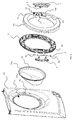
Fig. 3 is an exploded perspective view of the door assembly ofFig. 2 and of a front face of a casing of the laundry treatment device onto which the door assembly is supported; -
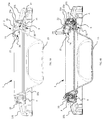
Figs. 4A and 4B are sectional lateral views of the door assembly and of the casing ofFig. 3 , with an handle of the door assembly in a resting position and in an unlocking position, respectively; -
Figs. 5A and 5B are a perspective and a front view, respectively, of the door assembly with the handle in the resting position; -
Figs. 6A and 6B are a perspective and a front view, respectively, of the door assembly with the handle in the unlocking position; -
Fig. 7 is an exploded perspective view, in an enlarge scale, of the handle and of a locking, device details of the door assembly according to the present invention; -
Fig. 8 is a perspective enlarged view of the handle and the locking device ofFig. 7 , when assembled; and -
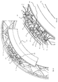
Figs. 9A and 9B are a perspective and a respective detail of the handle and the locking device mounted on a counter-frame of the door assembly according to the present invention. - With reference initially to
Figs. 1A and 1B , a laundry treatment device realized according to the present invention is globally indicated with thereference number 100. - It should be noted that in the context of the present invention with the term laundry treatment device it is to be intended any type of appliance suitable for the treatment of laundry, such as washing machines, tumble-dryers or washer/dryers, i.e. a washing machines having also dryer functions.
- The
laundry treatment device 100 comprises anouter casing 101, preferably but not necessarily parallelepiped-shaped, and a treatment chamber, such as adrum 102, for example having the shape of a hollow cylinder, for housing the laundry and in general the clothes and garments to be washed and/or dried. Thedrum 102 is preferably rotatably associated to the casing, so that it can rotate around an axis thereof. According to the present embodiment, the rotation axis of thedrum 102 is substantially horizontal but it should be appreciated that, as an alternative, the drum can be positioned in thecasing 101 in such a position that its rotation axis is tilted. - An
aperture 101a is defined in the casing, facing the treatment chamber and thus granting access to the drum for loading and unloading the laundry in the device. Thelaundry treatment device 100 further comprises adoor assembly 1 pivotally supported on thecasing 101 and displaceable between an open position, in which access to the drum is granted, and a closed position, in which theaperture 101a is closed or preferably sealed. - According to the present embodiment, the
aperture 101a is defined in a front face of thecasing 101; preferably, thedevice 100 comprises acontrol panel 103 placed in the front face of thecasing 101. Advantageously thedevice 100 comprises adrawer 104 suitable, ifdevice 100 is a washing machine or washer-drier, for containing detergents and other additives, and if thedevice 100 is a drier, for collecting water. - Always with reference to
Fig. 1 , thelaundry treatment device 100 further comprises alocking device 3 for locking thedoor assembly 1 in the closed position in which theaperture 101a is closed. According to a preferred embodiment, and as will be better shown in the following, the locking device comprises alatch 3 suitable for engaging in arespective hole 30 provided in saidcasing 101 in a position adjacent to theaperture 101a. Thelatch 3 is advantageously hook-shaped and it is engaged in thehole 30 in a locking position of the locking device, thus avoiding the opening of thedoor assembly 1, and disengaged from thehole 30 in a unlocking position in which the door assembly is free to rotate about an axis Z on which the door assembly is hinged. - With reference now also to
Figs. 2 and3 , thedoor assembly 1 comprises adoor frame 10 supporting thelatch 3 and, more in general, the locking device. Ahandle 2 operating the locking device is also supported on thedoor frame 10, operatively connected to thelocking device 3. Preferably, as will be also described in further detail in the following, thelatch 3 is pivotally supported on thedoor frame 10 and it is switched between the locking position and the unlocking position through a rotation thereof. - According to the present embodiment, the
door assembly 1 further comprises ascreen 15, preferably made of glass, allowing visual access to the treatment chamber when thedoor assembly 1 is closed. Thescreen 15 is supported internally on thedoor frame 10, defining an internal region thereof. Thedoor assembly 1 preferably further comprises a counter-frame 12 coupled to theframe 10 and between which anedge 15a of thescreen 15 is advantageously clamped. Advantageously, theframe 10 and the counter-frame 12 are fixed the one to the other, preferably by means of a snap connection, more preferably combined with screws, not shown in the Figures. - Preferably, the counter-frame 12 is formed by a honeycomb structure, thus improving the robustness of the door assembly.
- According to alternative embodiments, not illustrated in the Figures, the
door assembly 1 could be formed as a single piece, for example when visual access to thetreatment chamber 102 is not required. In these cases, the door frame could be preferably disk-shaped instead of being annular shaped as in the previous embodiment. - It should be also noted that in the previous embodiments the
door assembly 1 and theframe 10 are substantially circular, but even different shapes could be envisages. - With reference again to
Figs. 2 and3 , thedoor assembly 1 is supported pivotally on thecasing 101 by means of a hinge, preferably comprising asupport plate 6, and apin 60, onto which thedoor frame 10 is hinged about the axis Z. As shown inFig. 3 , thepin 60 is preferably clamped between the counter-frame 12 and theframe 10 and it is preferably locked by means of lockingheads 61 positioned at the opposed ends of thepin 60. - As shown in
Fig. 3 , arecess 11 is defined in thedoor frame 10 in which thehandle 2 is partially housed. According to a preferred embodiment, therecess 11 faces an internal region of thedoor assembly 1 that, in the present embodiment, corresponds to thescreen 15. - Advantageously, the
recess 11 does not spread to the entire width of thedoor frame 10; advantageously asurface 10a of the frame is defined around therecess 11. In the present embodiment, thesurface 10a advantageously faces frontally thelaundry treatment device 100, i.e. a user will face thesurface 10a when operating thedevice 100. - As it will be better apparent in the following, this position of the
recess 11 makes it possible to house thehandle 2 in thedoor frame 10 without excessively projecting from the periphery thereof, which helps reducing the overall external dimensions of the machine. - The
handle 2 is pivotally supported on thedoor frame 10 around an axis A and it is capable of performing a rotation α (see for exampleFig. 2 ) between a resting position and an unlocking position. In the resting position, which is shown inFigs. 4A ,5A and 5B , thehandle 2 operates thelocking device 3 so as to lock thedoor assembly 1. As shown inFig. 4A , in the resting position ahook portion 31 of thelatch 3 engages thehole 30 of thecasing 101, thus locking the door assembly in the closed position. According to a preferred embodiment, the rotation of thelatch 3 between the locking and the unlocking position is obtained by the rotation α of thehandle 2. The connection between thelatch 3 and thehandle 2 in order to couple their rotation and operate the former will be described in detail in the following. - In the unlocking position, shown in
Figs. 4B ,6A, 6B , thehandle 2 operates thelocking device 3 so as to unlock saiddoor assembly 1 by disengaging thehook 31 fromhole 30 and consequently allowing the rotation of the door assembly about axis Z. - Always with reference to
Fig. 4A and 4B , thehandle 2 comprises agrip portion 21 facing thescreen 15 or, more in general, the internal region of thedoor assembly 1. - Opposite to the
grip portion 21, the handle further comprises aflap 23 that, as apparent from the Figures, overlaps thesurface 10a adjacent to therecess 11 of thedoor frame 10 both in the resting and in the locking position of thehandle 2. In this manner the gap between the handle and therecess 11 is covered frontally by theflap 23 in any position of thehandle 2. In other words, this avoid the possibility of putting a finger in a potentially hazardous gap defined between therecess 11 and thehandle 2, since, as clearly shown inFig. 4B , said gap narrows when thehandle 2 is rotated. - Preferably, in order to avoid any risk of pinching one's finger,
door frame 10 andflap 23 are shaped such that a further gap is defined between thesurface 10a and anedge 23a of theflap 23 both in the resting position and in the unlocking position of thehandle 2. More preferably, the gap defined in the unlocking position is greater or equal to the gap defined in the resting position. - In this manner, even if a finger is placed in the gap when opening the
handle 2, there will be no risk of pinching it. - Always according to a preferred embodiment, the gap between the
edge 23a and thesurface 10a adjacent to therecess 11 is smaller than a finger thickness both in the resting position and in the unlocking position of thehandle 2. - It should be also noted that, advantageously, the
edge 23a of theflap 23 travels in the rotation α of thehandle 2 along a path without abutting against thesurface 10a adjacent to therecess 11. - This means that the
flap 23 does not enter into contact with thedoor frame 10 when the handle is rotated to its maximum extent. - Advantageously, the
handle 2 comprises amain body 20 suitable for being at least partially housed in therecess 11 and from which theflap 23 projects. - In this way, the rotation α can be advantageously limited by the contact of the
main body 20 with aside wall 13 of therecess 11, acting as a stop surface. Since the rotation of thehandle 2 is stopped by the contact of these relatively wide surfaces, excessive stresses on the components of thehandle 2, and in general of thedoor assembly 1, can be advantageously avoided even if it is further pulled. This improves the endurance of the door handle and of the door assembly. - Always according to a preferred embodiment, a
cavity 24 is also defined in themain body 20 of thehandle 2. Thecavity 24 is opposed to theflap 23 and thegrip portion 21 is defined by an internal surface of thecavity 24. - In this manner, the rotation α of the
handle 2 can be easily obtained by pulling thegrip portion 21 away from thedoor assembly 1, as shown by an arrow inFig. 4B . - Always according to
Fig. 4B , when thegrip portion 21 is pulled, and consequently thehandle 2 is rotated, thelatch 3 is also rotated accordingly, thus disengaging it fromhole 30. - Advantageously, the position of the
grip portion 21 together with the direction of the rotation α of thehandle 2 promotes the opening of the door assembly, as pointed out by the arrows inFig. 4B . - The provision of the
cavity 24 in themain body 20 of thehandle 2 is also advantageous since the user can easily reach thegrip portion 21 by putting his fingers therein. Also, it should be appreciated that since themain body 20 is housed in therecess 11, it is not required that thehandle 2 projects excessively from thedoor frame 2 in order to provide an ergonomic grip to the user. - As also shown in
Fig. 2 , in order to maximize the torque applied, thedoor 2 is hinged on a position diametrically opposed to thehandle 2 and, consequently, to thegrip portion 21. Preferably, the axis A of thehandle 2 is substantially parallel to the axis of rotation Z of thedoor assembly 1 relative to saidcasing 101. In this way, the pulling force on thegrip portion 21 is maximally effective in opening thedoor assembly 2. - Always according to a preferred embodiment, the
handle 2 is rotatable about apin 5, defining the axis A and supported on thedoor frame 10 or on the counter-frame. Themain body 20 is cantilevered from thepin 5 and it is pivotally connected to thispin 5 by at least one connectingarm 25 passing through arespective aperture 14 defined in therecess 11, as shown inFig. 4A . - In this manner,
flap 23 is separated frompin 5 by thesurface 10a, thus effectively protecting the locking device. Furthermore, since theflap 23 projects from themain body 20 which is in turn cantilevered from thepin 5, it is possible to protect any potentially hazardous gap with a compact structure. - Preferably, with reference to
Figs. 7 and8 , thehandle 2 comprises a pair of connectingarms 25, eacharm 25 being provided with arespective hole 26, into which thepin 5 is inserted. Between arms 25 a region is defined into which thelatch 3 is housed. - Preferably, the
latch 3 comprises anend portion 32, opposed to thehook 31 engaging in thehole 30, in which anaperture 32a is defined for pivotally supporting the latch on thepin 5. In this way, thehandle 2 and thelatch 3 are rotatable about the same axis A. - In order to couple the rotation of the
handle 2 and thelatch 3 the locking device comprises a resilient connector 4. As shown inFigs. 7 ,8 and9A , the resilient connector 4 comprises a pair ofarms 42 connected byrespective windings 41 to acentral portion 40 projecting in opposite direction relative thereto. -
Arms 42 rests on a restingsurface 27 of thehandle 2, while thecentral portion 40 surrounds thelatch 3. -
Windings 41 are concentric to axis A and, whenarms 42 are rotated around said axis, a corresponding rotation is provided to thecentral portion 40. Accordingly, a rotation of thehandle 2 is resiliently transmitted to thelatch 3 for the presence of thewindings 41. - It will be anyhow appreciated that the rotation of the
handle 2 could be transmitted to thelatch 3 in order to disengage it also in different manner and thehandle 2 and thelatch 3 can also be made as a single piece. - Always according to the present embodiment, the locking device further comprises a
resilient element 33 biasing saidlatch 3 into the locking position. Analogously to the resilient connector 4, theresilient element 33 comprises a pair ofarms 35 connected byrespective windings 34 to acentral portion 36 projecting in opposite direction relative thereto. - As shown in
Fig. 8 , thelatch 3 is clamped between thecentral portion 36 of theresilient element 33 and thecentral portion 40 of the resilient connector 4. In other words, the rotation of thelatch 3 is hindered in both directions. With reference then toFig. 9A ,arms 35 of theresilient element 33 rest onrespective projections 16 formed on thecounter-frame 12. This makes it possible to hold theresilient element 33 simply by clamping theframe 10 and thecounter frame 12 together. - It should also be appreciated that the provision of the
resilient element 33 advantageously permits that, when the door assembly is closed, thelatch 3 is forced in its locking position and the door assembly can be opened only if the locking device is operated by thehandle 2.
Claims (15)
- A laundry treatment device (100) comprising:• a casing (101) supporting a treatment chamber (102) for receiving laundry to be treated, said casing including an aperture (101a) for granting access to said treatment chamber (102);• a door assembly (1) pivotally mounted on said casing (101) and capable of opening and closing said aperture (101a):• a locking device (3) for locking said door assembly in a closed position in which said aperture (101a) is closed;• wherein said door assembly (1) comprises:said rotation (α) being obtained by pulling said grip portion (21) away from said door assembly (1).∘ a door frame (10) supporting said locking device (3) and in which a recess (11) is defined; and∘ a handle (2) which is:▪ partially housed in said recess (11);▪ pivotally supported on said door frame (10) and capable of performing a rotation (α) between a resting position in which said handle (2) operates said locking device (3) so as to lock the door assembly (1) and an unlocking position in which said handle (2) operates said locking device (3) so as to unlock said door assembly (1);characterizes in that
said handle (2) further comprises:▪ a grip portion (21) facing an internal region (15) of said door assembly (1); and▪ a flap (23) opposed to said grip portion (21) and overlapping a surface (10a) of said door frame (10) adjacent to said recess (11) both in the resting and in the locking position of said handle (2); - The laundry treatment device (100) according to claim 1, wherein said door frame (10) and said flap (23) are shaped such that a gap between said surface (10a) and an edge (23a) of said flap (23) is defined both in said resting position and in said unlocking position of said handle (2), the gap defined in said unlocking position being greater or equal to the gap defined in said resting position.
- The laundry treatment device (100) according to claim 1 or 2, wherein said handle (2) comprises a main body (20) suitable for being at least partially housed in said recess (11) and from which said flap (23) projects.
- The laundry treatment device (100) according to claim 3, wherein said handle (2) is rotatable about a pin (5) supported on said door frame (10), said main body (20) being cantilevered from said pin (5) and being pivotally connected to said pin (5) by at least one connecting arm (25) and wherein at least one aperture (14) is defined in said recess (11) through which said connecting arm (25) passes.
- The laundry treatment device (100) according to claim 3 or 4, wherein a cavity (24) is defined in said handle, said cavity (24) being opposed to said flap (23) and comprising said grip portion (21).
- The laundry treatment device (100) according to any of claims 3 to 5, wherein said rotation (α) is limited by the contact of said main body (20) with a side wall (13) of said recess (11).
- The laundry treatment device (100) according to any of the preceding claims, wherein said locking device comprises a latch (3), suitable for engaging in a respective hole (30) provided in said casing (101), the latch (3) being engaged in said hole (30) in said locking position and disengaged in said unlocking position.
- The laundry treatment device (100) according to claim 7, wherein said latch (3) is pivotally supported on said door frame (10) and is switched between said locking position and said unlocking position through a rotation thereof.
- The laundry treatment device (100) according to claim 8, wherein said latch (3) is rotated by means of said rotation (α) of said handle (2).
- The laundry treatment device (100) according to claim 9, wherein said handle (2) and said latch (3) are rotatable about a same axis (A).
- The laundry treatment device (100) according to claim 10, wherein said axis (A) is substantially parallel to an axis of rotation (Z) of said door assembly (1) relative to said casing (101).
- The laundry treatment device (100) according to any of claims 7 to 11, wherein said handle (2) is connected to said latch (3) by means of a resilient connector (4).
- The laundry treatment device (100) according to any of claims 7 to 12, wherein said locking device comprises a resilient element (33) biasing said latch (3) into said locking position.
- The laundry treatment device (100) according to any of claims 2 to 13, wherein said edge (23a) of said flap (23) travels in said rotation (α) of said handle along a path without intersecting said surface (10a) of said door frame (10) overlapped by said flap (23).
- The laundry treatment device (100) according to any of claims 2 to 14, wherein said gap between said edge (23a) and said surface (10a) adjacent to the recess (11) is smaller than a finger thickness.
Priority Applications (1)
| Application Number | Priority Date | Filing Date | Title |
|---|---|---|---|
| EP13801589.6A EP2929077B1 (en) | 2012-12-06 | 2013-12-06 | Laundry treatment device with door assembly |
Applications Claiming Priority (3)
| Application Number | Priority Date | Filing Date | Title |
|---|---|---|---|
| EP12195895.3A EP2740832A1 (en) | 2012-12-06 | 2012-12-06 | Laundry treatment device with door assembly |
| PCT/EP2013/075854 WO2014086997A1 (en) | 2012-12-06 | 2013-12-06 | Laundry treatment device with door assembly |
| EP13801589.6A EP2929077B1 (en) | 2012-12-06 | 2013-12-06 | Laundry treatment device with door assembly |
Publications (2)
| Publication Number | Publication Date |
|---|---|
| EP2929077A1 EP2929077A1 (en) | 2015-10-14 |
| EP2929077B1 true EP2929077B1 (en) | 2016-09-28 |
Family
ID=47429590
Family Applications (2)
| Application Number | Title | Priority Date | Filing Date |
|---|---|---|---|
| EP12195895.3A Withdrawn EP2740832A1 (en) | 2012-12-06 | 2012-12-06 | Laundry treatment device with door assembly |
| EP13801589.6A Active EP2929077B1 (en) | 2012-12-06 | 2013-12-06 | Laundry treatment device with door assembly |
Family Applications Before (1)
| Application Number | Title | Priority Date | Filing Date |
|---|---|---|---|
| EP12195895.3A Withdrawn EP2740832A1 (en) | 2012-12-06 | 2012-12-06 | Laundry treatment device with door assembly |
Country Status (2)
| Country | Link |
|---|---|
| EP (2) | EP2740832A1 (en) |
| WO (1) | WO2014086997A1 (en) |
Cited By (2)
| Publication number | Priority date | Publication date | Assignee | Title |
|---|---|---|---|---|
| EP4481101A1 (en) | 2023-06-23 | 2024-12-25 | Arçelik Anonim Sirketi | A laundry washer and/or dryer comprising a door |
| US12674270B2 (en) | 2024-07-18 | 2026-07-07 | Haier Us Appliance Solutions, Inc. | Door assembly for a laundry appliance |
Families Citing this family (3)
| Publication number | Priority date | Publication date | Assignee | Title |
|---|---|---|---|---|
| WO2016070889A1 (en) * | 2014-11-03 | 2016-05-12 | Arcelik Anonim Sirketi | Laundry washing/drying machine front door with a mechanically improved locking mechanism |
| DE102017108709B3 (en) * | 2017-04-24 | 2018-09-13 | Miele & Cie. Kg | Door handle, door and front-loading household appliance, such as washing machine, tumble dryer or washer-dryer |
| EP3502341B1 (en) * | 2017-12-22 | 2021-12-08 | Electrolux Appliances Aktiebolag | Laundry treatment machine |
Family Cites Families (8)
| Publication number | Priority date | Publication date | Assignee | Title |
|---|---|---|---|---|
| GB2081858B (en) | 1980-08-08 | 1984-01-18 | Philips Electronic Associated | Domestic appliance |
| DE4216580C2 (en) * | 1992-05-20 | 1994-05-19 | Miele & Cie | Laundry treatment machine with a door that is suspended on the washing unit |
| DE10056985B4 (en) | 2000-11-17 | 2006-11-30 | BSH Bosch und Siemens Hausgeräte GmbH | Catch lock for a window or flap |
| KR20040105342A (en) * | 2003-06-07 | 2004-12-16 | 삼성전자주식회사 | Washing Machine |
| KR101054404B1 (en) | 2004-02-13 | 2011-08-04 | 엘지전자 주식회사 | Door of drum washing machine |
| WO2007110442A1 (en) | 2006-03-29 | 2007-10-04 | Arcelik Anonim Sirketi | A locking mechanism for a household appliance |
| DE102006029483A1 (en) | 2006-06-27 | 2008-01-03 | BSH Bosch und Siemens Hausgeräte GmbH | Flap for a household appliance |
| KR101555478B1 (en) | 2008-11-10 | 2015-09-25 | 삼성전자 주식회사 | washing machine door assembling structure and assembling method of the same |
-
2012
- 2012-12-06 EP EP12195895.3A patent/EP2740832A1/en not_active Withdrawn
-
2013
- 2013-12-06 EP EP13801589.6A patent/EP2929077B1/en active Active
- 2013-12-06 WO PCT/EP2013/075854 patent/WO2014086997A1/en not_active Ceased
Non-Patent Citations (1)
| Title |
|---|
| None * |
Cited By (2)
| Publication number | Priority date | Publication date | Assignee | Title |
|---|---|---|---|---|
| EP4481101A1 (en) | 2023-06-23 | 2024-12-25 | Arçelik Anonim Sirketi | A laundry washer and/or dryer comprising a door |
| US12674270B2 (en) | 2024-07-18 | 2026-07-07 | Haier Us Appliance Solutions, Inc. | Door assembly for a laundry appliance |
Also Published As
| Publication number | Publication date |
|---|---|
| WO2014086997A1 (en) | 2014-06-12 |
| EP2929077A1 (en) | 2015-10-14 |
| EP2740832A1 (en) | 2014-06-11 |
Similar Documents
| Publication | Publication Date | Title |
|---|---|---|
| RU2534874C1 (en) | Device for laundry processing | |
| US8844328B2 (en) | Door of a household electrical appliance | |
| US9650737B2 (en) | Laundry treating apparatus | |
| EP2843105B1 (en) | A door assembly for a laundry treatment device and method of operation | |
| EP2929076B1 (en) | Laundry machine | |
| KR101481553B1 (en) | Door of drum washing machine | |
| EP2740832A1 (en) | Laundry treatment device with door assembly | |
| EP1486604A2 (en) | Door locking mechanism | |
| KR101443636B1 (en) | Door of drum type washing machine | |
| US20130232810A1 (en) | Door handle for a washing machine or dryer appliance | |
| EP0859079B1 (en) | Hinge for electrical appliance door, particularly for laundry washing and/or drying machine | |
| US9790633B2 (en) | Laundry treating apparatus | |
| EP1826309B1 (en) | Closure device for the door of an apparatus comprising a rotary drum, and latch for one such device | |
| EP2808434B1 (en) | Laundry treatment device with door assembly | |
| AU2014314511B2 (en) | Door assembly for a laundry treatment device | |
| KR20100089380A (en) | Door locking switch and a cloth treating apparatus | |
| CN101792965B (en) | Laundry care device with a horizontally pivoting grip element | |
| JP6568814B2 (en) | Clothing processing equipment | |
| SI23836A (en) | Domestic appliance door handle | |
| JP7488845B2 (en) | Clothes Processing Equipment | |
| JPH0319360Y2 (en) | ||
| KR101147751B1 (en) | Door assembly | |
| WO2018103832A1 (en) | A laundry treatment appliance having an improved door handle assembly | |
| JP2004121355A (en) | Clothes dryer | |
| EP3440255A1 (en) | Laundry dryer having a door with improved usability |
Legal Events
| Date | Code | Title | Description |
|---|---|---|---|
| PUAI | Public reference made under article 153(3) epc to a published international application that has entered the european phase |
Free format text: ORIGINAL CODE: 0009012 |
|
| 17P | Request for examination filed |
Effective date: 20150706 |
|
| AK | Designated contracting states |
Kind code of ref document: A1 Designated state(s): AL AT BE BG CH CY CZ DE DK EE ES FI FR GB GR HR HU IE IS IT LI LT LU LV MC MK MT NL NO PL PT RO RS SE SI SK SM TR |
|
| AX | Request for extension of the european patent |
Extension state: BA ME |
|
| DAX | Request for extension of the european patent (deleted) | ||
| GRAP | Despatch of communication of intention to grant a patent |
Free format text: ORIGINAL CODE: EPIDOSNIGR1 |
|
| INTG | Intention to grant announced |
Effective date: 20160509 |
|
| GRAP | Despatch of communication of intention to grant a patent |
Free format text: ORIGINAL CODE: EPIDOSNIGR1 |
|
| INTG | Intention to grant announced |
Effective date: 20160712 |
|
| GRAS | Grant fee paid |
Free format text: ORIGINAL CODE: EPIDOSNIGR3 |
|
| GRAA | (expected) grant |
Free format text: ORIGINAL CODE: 0009210 |
|
| AK | Designated contracting states |
Kind code of ref document: B1 Designated state(s): AL AT BE BG CH CY CZ DE DK EE ES FI FR GB GR HR HU IE IS IT LI LT LU LV MC MK MT NL NO PL PT RO RS SE SI SK SM TR |
|
| REG | Reference to a national code |
Ref country code: GB Ref legal event code: FG4D |
|
| REG | Reference to a national code |
Ref country code: CH Ref legal event code: EP |
|
| REG | Reference to a national code |
Ref country code: AT Ref legal event code: REF Ref document number: 832862 Country of ref document: AT Kind code of ref document: T Effective date: 20161015 |
|
| REG | Reference to a national code |
Ref country code: IE Ref legal event code: FG4D |
|
| REG | Reference to a national code |
Ref country code: DE Ref legal event code: R096 Ref document number: 602013012268 Country of ref document: DE |
|
| REG | Reference to a national code |
Ref country code: FR Ref legal event code: PLFP Year of fee payment: 4 |
|
| REG | Reference to a national code |
Ref country code: LT Ref legal event code: MG4D |
|
| PG25 | Lapsed in a contracting state [announced via postgrant information from national office to epo] |
Ref country code: HR Free format text: LAPSE BECAUSE OF FAILURE TO SUBMIT A TRANSLATION OF THE DESCRIPTION OR TO PAY THE FEE WITHIN THE PRESCRIBED TIME-LIMIT Effective date: 20160928 Ref country code: LT Free format text: LAPSE BECAUSE OF FAILURE TO SUBMIT A TRANSLATION OF THE DESCRIPTION OR TO PAY THE FEE WITHIN THE PRESCRIBED TIME-LIMIT Effective date: 20160928 Ref country code: RS Free format text: LAPSE BECAUSE OF FAILURE TO SUBMIT A TRANSLATION OF THE DESCRIPTION OR TO PAY THE FEE WITHIN THE PRESCRIBED TIME-LIMIT Effective date: 20160928 Ref country code: FI Free format text: LAPSE BECAUSE OF FAILURE TO SUBMIT A TRANSLATION OF THE DESCRIPTION OR TO PAY THE FEE WITHIN THE PRESCRIBED TIME-LIMIT Effective date: 20160928 Ref country code: NO Free format text: LAPSE BECAUSE OF FAILURE TO SUBMIT A TRANSLATION OF THE DESCRIPTION OR TO PAY THE FEE WITHIN THE PRESCRIBED TIME-LIMIT Effective date: 20161228 |
|
| REG | Reference to a national code |
Ref country code: NL Ref legal event code: MP Effective date: 20160928 |
|
| REG | Reference to a national code |
Ref country code: AT Ref legal event code: MK05 Ref document number: 832862 Country of ref document: AT Kind code of ref document: T Effective date: 20160928 |
|
| PG25 | Lapsed in a contracting state [announced via postgrant information from national office to epo] |
Ref country code: SE Free format text: LAPSE BECAUSE OF FAILURE TO SUBMIT A TRANSLATION OF THE DESCRIPTION OR TO PAY THE FEE WITHIN THE PRESCRIBED TIME-LIMIT Effective date: 20160928 Ref country code: GR Free format text: LAPSE BECAUSE OF FAILURE TO SUBMIT A TRANSLATION OF THE DESCRIPTION OR TO PAY THE FEE WITHIN THE PRESCRIBED TIME-LIMIT Effective date: 20161229 Ref country code: NL Free format text: LAPSE BECAUSE OF FAILURE TO SUBMIT A TRANSLATION OF THE DESCRIPTION OR TO PAY THE FEE WITHIN THE PRESCRIBED TIME-LIMIT Effective date: 20160928 Ref country code: LV Free format text: LAPSE BECAUSE OF FAILURE TO SUBMIT A TRANSLATION OF THE DESCRIPTION OR TO PAY THE FEE WITHIN THE PRESCRIBED TIME-LIMIT Effective date: 20160928 |
|
| PGFP | Annual fee paid to national office [announced via postgrant information from national office to epo] |
Ref country code: FR Payment date: 20161222 Year of fee payment: 4 |
|
| PG25 | Lapsed in a contracting state [announced via postgrant information from national office to epo] |
Ref country code: EE Free format text: LAPSE BECAUSE OF FAILURE TO SUBMIT A TRANSLATION OF THE DESCRIPTION OR TO PAY THE FEE WITHIN THE PRESCRIBED TIME-LIMIT Effective date: 20160928 Ref country code: RO Free format text: LAPSE BECAUSE OF FAILURE TO SUBMIT A TRANSLATION OF THE DESCRIPTION OR TO PAY THE FEE WITHIN THE PRESCRIBED TIME-LIMIT Effective date: 20160928 |
|
| PG25 | Lapsed in a contracting state [announced via postgrant information from national office to epo] |
Ref country code: BE Free format text: LAPSE BECAUSE OF FAILURE TO SUBMIT A TRANSLATION OF THE DESCRIPTION OR TO PAY THE FEE WITHIN THE PRESCRIBED TIME-LIMIT Effective date: 20160928 Ref country code: AT Free format text: LAPSE BECAUSE OF FAILURE TO SUBMIT A TRANSLATION OF THE DESCRIPTION OR TO PAY THE FEE WITHIN THE PRESCRIBED TIME-LIMIT Effective date: 20160928 Ref country code: IS Free format text: LAPSE BECAUSE OF FAILURE TO SUBMIT A TRANSLATION OF THE DESCRIPTION OR TO PAY THE FEE WITHIN THE PRESCRIBED TIME-LIMIT Effective date: 20170128 Ref country code: PL Free format text: LAPSE BECAUSE OF FAILURE TO SUBMIT A TRANSLATION OF THE DESCRIPTION OR TO PAY THE FEE WITHIN THE PRESCRIBED TIME-LIMIT Effective date: 20160928 Ref country code: ES Free format text: LAPSE BECAUSE OF FAILURE TO SUBMIT A TRANSLATION OF THE DESCRIPTION OR TO PAY THE FEE WITHIN THE PRESCRIBED TIME-LIMIT Effective date: 20160928 Ref country code: CZ Free format text: LAPSE BECAUSE OF FAILURE TO SUBMIT A TRANSLATION OF THE DESCRIPTION OR TO PAY THE FEE WITHIN THE PRESCRIBED TIME-LIMIT Effective date: 20160928 Ref country code: SK Free format text: LAPSE BECAUSE OF FAILURE TO SUBMIT A TRANSLATION OF THE DESCRIPTION OR TO PAY THE FEE WITHIN THE PRESCRIBED TIME-LIMIT Effective date: 20160928 Ref country code: SM Free format text: LAPSE BECAUSE OF FAILURE TO SUBMIT A TRANSLATION OF THE DESCRIPTION OR TO PAY THE FEE WITHIN THE PRESCRIBED TIME-LIMIT Effective date: 20160928 Ref country code: BG Free format text: LAPSE BECAUSE OF FAILURE TO SUBMIT A TRANSLATION OF THE DESCRIPTION OR TO PAY THE FEE WITHIN THE PRESCRIBED TIME-LIMIT Effective date: 20161228 Ref country code: PT Free format text: LAPSE BECAUSE OF FAILURE TO SUBMIT A TRANSLATION OF THE DESCRIPTION OR TO PAY THE FEE WITHIN THE PRESCRIBED TIME-LIMIT Effective date: 20170130 |
|
| REG | Reference to a national code |
Ref country code: DE Ref legal event code: R097 Ref document number: 602013012268 Country of ref document: DE |
|
| PG25 | Lapsed in a contracting state [announced via postgrant information from national office to epo] |
Ref country code: DK Free format text: LAPSE BECAUSE OF FAILURE TO SUBMIT A TRANSLATION OF THE DESCRIPTION OR TO PAY THE FEE WITHIN THE PRESCRIBED TIME-LIMIT Effective date: 20160928 |
|
| REG | Reference to a national code |
Ref country code: CH Ref legal event code: PL |
|
| PLBE | No opposition filed within time limit |
Free format text: ORIGINAL CODE: 0009261 |
|
| STAA | Information on the status of an ep patent application or granted ep patent |
Free format text: STATUS: NO OPPOSITION FILED WITHIN TIME LIMIT |
|
| 26N | No opposition filed |
Effective date: 20170629 |
|
| PG25 | Lapsed in a contracting state [announced via postgrant information from national office to epo] |
Ref country code: MC Free format text: LAPSE BECAUSE OF FAILURE TO SUBMIT A TRANSLATION OF THE DESCRIPTION OR TO PAY THE FEE WITHIN THE PRESCRIBED TIME-LIMIT Effective date: 20160928 |
|
| REG | Reference to a national code |
Ref country code: IE Ref legal event code: MM4A |
|
| PG25 | Lapsed in a contracting state [announced via postgrant information from national office to epo] |
Ref country code: LI Free format text: LAPSE BECAUSE OF NON-PAYMENT OF DUE FEES Effective date: 20161231 Ref country code: LU Free format text: LAPSE BECAUSE OF NON-PAYMENT OF DUE FEES Effective date: 20161206 Ref country code: CH Free format text: LAPSE BECAUSE OF NON-PAYMENT OF DUE FEES Effective date: 20161231 |
|
| PG25 | Lapsed in a contracting state [announced via postgrant information from national office to epo] |
Ref country code: IE Free format text: LAPSE BECAUSE OF NON-PAYMENT OF DUE FEES Effective date: 20161206 Ref country code: SI Free format text: LAPSE BECAUSE OF FAILURE TO SUBMIT A TRANSLATION OF THE DESCRIPTION OR TO PAY THE FEE WITHIN THE PRESCRIBED TIME-LIMIT Effective date: 20160928 |
|
| PG25 | Lapsed in a contracting state [announced via postgrant information from national office to epo] |
Ref country code: HU Free format text: LAPSE BECAUSE OF FAILURE TO SUBMIT A TRANSLATION OF THE DESCRIPTION OR TO PAY THE FEE WITHIN THE PRESCRIBED TIME-LIMIT; INVALID AB INITIO Effective date: 20131206 |
|
| PG25 | Lapsed in a contracting state [announced via postgrant information from national office to epo] |
Ref country code: MK Free format text: LAPSE BECAUSE OF FAILURE TO SUBMIT A TRANSLATION OF THE DESCRIPTION OR TO PAY THE FEE WITHIN THE PRESCRIBED TIME-LIMIT Effective date: 20160928 Ref country code: CY Free format text: LAPSE BECAUSE OF FAILURE TO SUBMIT A TRANSLATION OF THE DESCRIPTION OR TO PAY THE FEE WITHIN THE PRESCRIBED TIME-LIMIT Effective date: 20160928 |
|
| GBPC | Gb: european patent ceased through non-payment of renewal fee |
Effective date: 20171206 |
|
| PG25 | Lapsed in a contracting state [announced via postgrant information from national office to epo] |
Ref country code: MT Free format text: LAPSE BECAUSE OF NON-PAYMENT OF DUE FEES Effective date: 20161206 |
|
| REG | Reference to a national code |
Ref country code: FR Ref legal event code: ST Effective date: 20180831 |
|
| PG25 | Lapsed in a contracting state [announced via postgrant information from national office to epo] |
Ref country code: TR Free format text: LAPSE BECAUSE OF FAILURE TO SUBMIT A TRANSLATION OF THE DESCRIPTION OR TO PAY THE FEE WITHIN THE PRESCRIBED TIME-LIMIT Effective date: 20160928 Ref country code: AL Free format text: LAPSE BECAUSE OF FAILURE TO SUBMIT A TRANSLATION OF THE DESCRIPTION OR TO PAY THE FEE WITHIN THE PRESCRIBED TIME-LIMIT Effective date: 20160928 Ref country code: FR Free format text: LAPSE BECAUSE OF NON-PAYMENT OF DUE FEES Effective date: 20180102 |
|
| PG25 | Lapsed in a contracting state [announced via postgrant information from national office to epo] |
Ref country code: GB Free format text: LAPSE BECAUSE OF NON-PAYMENT OF DUE FEES Effective date: 20171206 |
|
| P01 | Opt-out of the competence of the unified patent court (upc) registered |
Effective date: 20230625 |
|
| PGFP | Annual fee paid to national office [announced via postgrant information from national office to epo] |
Ref country code: IT Payment date: 20251218 Year of fee payment: 13 |
|
| PGFP | Annual fee paid to national office [announced via postgrant information from national office to epo] |
Ref country code: DE Payment date: 20251229 Year of fee payment: 13 |