EP2928175A1 - Image sensor, method for transmitting data from same, information processing device, information processing method, electronic device, and program - Google Patents
Image sensor, method for transmitting data from same, information processing device, information processing method, electronic device, and program Download PDFInfo
- Publication number
- EP2928175A1 EP2928175A1 EP13858899.1A EP13858899A EP2928175A1 EP 2928175 A1 EP2928175 A1 EP 2928175A1 EP 13858899 A EP13858899 A EP 13858899A EP 2928175 A1 EP2928175 A1 EP 2928175A1
- Authority
- EP
- European Patent Office
- Prior art keywords
- data
- unit
- format
- compression
- original image
- Prior art date
- Legal status (The legal status is an assumption and is not a legal conclusion. Google has not performed a legal analysis and makes no representation as to the accuracy of the status listed.)
- Ceased
Links
Images







Classifications
-
- H—ELECTRICITY
- H04—ELECTRIC COMMUNICATION TECHNIQUE
- H04N—PICTORIAL COMMUNICATION, e.g. TELEVISION
- H04N1/00—Scanning, transmission or reproduction of documents or the like, e.g. facsimile transmission; Details thereof
- H04N1/41—Bandwidth or redundancy reduction
-
- H—ELECTRICITY
- H04—ELECTRIC COMMUNICATION TECHNIQUE
- H04N—PICTORIAL COMMUNICATION, e.g. TELEVISION
- H04N1/00—Scanning, transmission or reproduction of documents or the like, e.g. facsimile transmission; Details thereof
- H04N1/00127—Connection or combination of a still picture apparatus with another apparatus, e.g. for storage, processing or transmission of still picture signals or of information associated with a still picture
- H04N1/00204—Connection or combination of a still picture apparatus with another apparatus, e.g. for storage, processing or transmission of still picture signals or of information associated with a still picture with a digital computer or a digital computer system, e.g. an internet server
- H04N1/00209—Transmitting or receiving image data, e.g. facsimile data, via a computer, e.g. using e-mail, a computer network, the internet, I-fax
-
- H—ELECTRICITY
- H04—ELECTRIC COMMUNICATION TECHNIQUE
- H04N—PICTORIAL COMMUNICATION, e.g. TELEVISION
- H04N1/00—Scanning, transmission or reproduction of documents or the like, e.g. facsimile transmission; Details thereof
- H04N1/21—Intermediate information storage
- H04N1/2104—Intermediate information storage for one or a few pictures
- H04N1/2112—Intermediate information storage for one or a few pictures using still video cameras
-
- H—ELECTRICITY
- H04—ELECTRIC COMMUNICATION TECHNIQUE
- H04N—PICTORIAL COMMUNICATION, e.g. TELEVISION
- H04N19/00—Methods or arrangements for coding, decoding, compressing or decompressing digital video signals
- H04N19/10—Methods or arrangements for coding, decoding, compressing or decompressing digital video signals using adaptive coding
- H04N19/102—Methods or arrangements for coding, decoding, compressing or decompressing digital video signals using adaptive coding characterised by the element, parameter or selection affected or controlled by the adaptive coding
- H04N19/115—Selection of the code volume for a coding unit prior to coding
-
- H—ELECTRICITY
- H04—ELECTRIC COMMUNICATION TECHNIQUE
- H04N—PICTORIAL COMMUNICATION, e.g. TELEVISION
- H04N19/00—Methods or arrangements for coding, decoding, compressing or decompressing digital video signals
- H04N19/10—Methods or arrangements for coding, decoding, compressing or decompressing digital video signals using adaptive coding
- H04N19/134—Methods or arrangements for coding, decoding, compressing or decompressing digital video signals using adaptive coding characterised by the element, parameter or criterion affecting or controlling the adaptive coding
- H04N19/154—Measured or subjectively estimated visual quality after decoding, e.g. measurement of distortion
-
- H—ELECTRICITY
- H04—ELECTRIC COMMUNICATION TECHNIQUE
- H04N—PICTORIAL COMMUNICATION, e.g. TELEVISION
- H04N23/00—Cameras or camera modules comprising electronic image sensors; Control thereof
- H04N23/60—Control of cameras or camera modules
-
- H—ELECTRICITY
- H04—ELECTRIC COMMUNICATION TECHNIQUE
- H04N—PICTORIAL COMMUNICATION, e.g. TELEVISION
- H04N23/00—Cameras or camera modules comprising electronic image sensors; Control thereof
- H04N23/80—Camera processing pipelines; Components thereof
-
- H—ELECTRICITY
- H04—ELECTRIC COMMUNICATION TECHNIQUE
- H04N—PICTORIAL COMMUNICATION, e.g. TELEVISION
- H04N25/00—Circuitry of solid-state image sensors [SSIS]; Control thereof
-
- H—ELECTRICITY
- H04—ELECTRIC COMMUNICATION TECHNIQUE
- H04N—PICTORIAL COMMUNICATION, e.g. TELEVISION
- H04N25/00—Circuitry of solid-state image sensors [SSIS]; Control thereof
- H04N25/70—SSIS architectures; Circuits associated therewith
- H04N25/76—Addressed sensors, e.g. MOS or CMOS sensors
Definitions
- a bit length of the transmission format may be different from a bit length of the compression format.
- the compression unit may perform compression into the compression format in a unit of the plurality pieces of pixel data of the original image, and the conversion unit may convert the compression format which is compressed in the unit of the plurality of pieces of pixel data of the original image into the plurality of transmission formats.
- the bit length of the transmission format may be identical to the bit length of the compression format.
- An electronic device of the fourth aspect of the present technique includes: a decompression unit configured to decompress a transmission format of a plurality of pieces of pixel data of an original image, which format is converted from a compression format of the plurality of pieces of pixel data of the original image into which compression format the plurality of pieces of pixel data of the original image is compressed, into the compression format of the plurality of pieces of pixel data, and an expansion unit configured to expand the compression format decompressed by the decompression unit into the plurality of pieces of pixel data of the original image.
- two transmission units are provided in the image sensor 11 and two reception units are provided in the DSP 12 correspondingly.
- two transmission units are provided in the image sensor 11 and two reception units are provided in the DSP 12 correspondingly.
- a 3D image including a left-eye image imaged by the image sensor 11-1 and a right-eye image imaged by the image sensor 11-2. There is a parallax between the left-eye image and the right-eye image.
- the LINK-TX protocol management unit 61 includes a state control unit 71, a header generation unit 72, a data insertion unit 73, and a footer generation unit 74.
- the whole one packet includes a header and payload data which is pixel data in one line. There is a case where a footer is added to the packet.
- the header includes header information and a Header ECC.
- the Line Number is 13-bit information indicating a line number of a line including pixel data stored in a payload.
- the header generation unit 72 generates a pair of header information and a CRC code by adding the CRC code to the header information. By repeatedly arranging the same pair of header information and a CRC code for three times, the header generation unit 72 generates a header. The header generation unit 72 outputs the generated header to the packet generation unit 64.
- control code there are an Idle Code, a Start Code, an End Code, a Pad Code, an Sync Code, a Deskew Code, and an Standby Code.
- the Idle Code is a symbol group repeatedly transmitted in a period other than transmission of packet data.
- the Idle Code is expressed by D00.0 (00000000) of a D Character which is an 8B10B Code.
- the signal processing units 102-0 to 102-N are provided, the number thereof being the same with the number of Lanes. Processing of packet data transmitted by using each Lane is performed in parallel in the signal processing units 102-0 to 102-N. A configuration of the signal processing unit 102-0 will be described. Each of the signal processing units 102-1 to 102-N includes a similar configuration.
- the reception unit 111 receives a signal indicating the packet data transmitted from the transmission unit 22 through the transmission path included in the Lane 0 and outputs the signal to the clock generation unit 112.
- the clock generation unit 112 By detecting an edge of the signal supplied by the reception unit 111, the clock generation unit 112 performs bit synchronization and generates a clock signal based on a detection cycle of the edge.
- the clock generation unit 112 outputs the signal, which is supplied by the reception unit 111, to the synchronization unit 113 along with the clock signal.
- the packet separation unit 123 separates the packet data of one packet, which data is integrated by the Lane integration unit 122, into packet data included in header data and packet data included in payload data.
- the packet separation unit 123 outputs the header data to the header error correction unit 132 and outputs the payload data to the payload error correction unit 124.
- the header error correction unit 132 estimates correct header information and outputs header information, which is estimated as the correct information, and a decoding result.
- the data calculated by the error detection calculation is a value calculated by applying a generator polynomial of the CRC to the header information.
- the decoding result is information indicating that decoding is successful or unsuccessful.
- step S2 data transmission processing is performed by the transmission unit 22.
- a packet which stores, in a payload, pixel data in one line is generated and packet data included in the packet is transmitted to the reception unit 31.
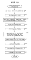
- the data transmission processing will be described later with reference to a flowchart in Fig. 10 .
- step S6 the image processing unit 32 performs image processing by using the image in the one frame and ends the processing.
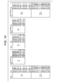
- a second column from the right is a compression data format inversely converted from the transmission data format in the processing described later and the rightmost column indicates an original image data format which is an expanded compression data format. Also, in a case of the leftmost column, D_N[11] indicates an MSB and D_N[0] which is the smallest number indicates an LSB. Similar indication is made in the other lines.
- step S38 the packet separation unit 123 separates the packet data, which is integrated by the Lane integration unit 122, into packet data included in the header data and packet data included in the payload data.
- the expansion unit 144 respectively expands the data COMP_N+2[0] to [4] and COMP_N+3[0] to [4] of the data Data4*N+1 into D_N+2[0] to [11] and D_N+3[0] to [11] and arranges the pieces of expanded data in the data Pixel8*N+2 and Pixel8*N+3. Also, the expansion unit 144 respectively expands the data COMP_N+4[0] to [4] and COMP_N+5[0] to [4] of the data Data4*N+2 into D_N+4[0] to [11] and D_N+5[0] to [11] and arranges the expanded data in the data Pixel8*N+4 and Pixel8*N+5.
- step S40 ByteN in the transmission data format illustrated in the third column from the left in Fig. 14 is converted into the data DataN in the compression data format including a structure identical to that of the eight-bit original image data format illustrated in the second column from the right in Fig. 14 . That is, the conversion unit 125 arranges, into the data DataN in the compression data format, the data COMP_N[0] to [3] and COMP_N+1[0] to [3] of the data ByteN in the transmission data format.
- the conversion unit 62 arranges the data COMP_N+3[0] to [3] and the data COMP_N+4[0] to [3] of the data Data2*N+1 into the data Byte3*N+1 and arranges the data COMP_N+2[0] to [3] and COMP_N+5[0] to [3] respectively including lower four bits of the data Data2*N and lower four bits of the data Data2*N+1 into the data Byte3*N+2.
- step S40 Byte3*N to Byte3*N+2 in the transmission data format illustrated in the third column from the left in Fig. 15 are converted into the data Data2*N and Data2*N+1 in the compression data format which includes a structure identical to that of the 12-bit original image data format and which is illustrated in the second column from the right in Fig. 15 . That is, the conversion unit 125 arranges, into the data Data2*N in the compression data format, the data COMP_N[0] to [3] and the data COMP_N+1[0] to [3] of the data Byte3*N in the transmission data format and the data COMP_N+2[0] to [3] of the data Byte3*N+2.
- the data Data2*N and Data2*N+1 in the compression data format including a structure identical to that of the 12-bit original image data format illustrated in the second column from the right in Fig. 15 is expanded into the data Pixel6*N to Pixel6*N+5 in the original image data format illustrated in the rightmost column in Fig. 15 .
- the expansion unit 144 respectively expands the four-bit data COMP_N[0] to [3] to COMP_N+2[0] to [3] of the data Data2*N in the four-bit compression data format of three pixels which format includes a structure identical to that of the 12-bit original image data format into D_N[0] to [11] to D_N+2[0] to [11] and arranges the expanded data into the data Pixel6*N to Pixel6*N+2 in the 12-bit original image data format.
- the conversion unit 125 arranges the data COMP_N+2[0] to [5] and the data COMP_N+3[4] to [5] of the data Byte3*N+2 and the data COMP_N+5[0] to [3] of the data Byte3*N+2 into the data Data2*N+1.
- the expansion unit 144 respectively expands the six-bit data COMP_N[0] to [5] to COMP_N+1[0] to [5] of the data Data2*N in the six-bit compression data format of two pixels which format includes a structure identical to that of the 12-bit original image data format into D_N[0] to [9] and D_N+1[0] to [9] and arranges the expanded data into the data Pixel4*N and Pixel4*N+1 in the 10-bit original image data format.
- the compression unit 54 compresses the 10-bit data D_N[0] to [9] to D_N+7[0] to [9] of the data Pixel8*N to Pixel8*N+7 in the original image data format into five bits and performs conversion into the data COMP_N[0] to [4] to COMP_N+7[0] to [4]. Moreover, as illustrated in the second column from the left in Fig.
- the data Byte5*N to Byte5*N+4 in a transmission data format illustrated in the third column from the left in Fig. 17 is converted into the data Data4*N to Data4*N+3 in a compression data format which includes a structure identical to that of the 10-bit original image data format and which is illustrated in the second column from the right in Fig. 17 . That is, the conversion unit 125 arranges the data COMP_N[0] to [4] and the data COMP_N+1[2] to [4] of the data Byte5*N in the transmission data format and the data COMP_N+1[0] to [1] of the data Byte5*N+4 into the data Data4*N in a compression data format.
- the conversion unit 125 arranges the data COMP_N+2[0] to [4] and the data COMP_N+3[2] to [4] of the data Byte5*N+1 and the data COMP_N+3[0] to [1] of the data Byte5*N+4 into the data Data4*N+1, arranges the data COMP_N+4[0] to [4] and the data COMP_N+5[2] to [4] of the data Byte5*N+2 and the data COMP_N+5[0] to [1] of the data Byte5*N+4 into the data Data4*N+2, and arranges the data COMP_N+6[0] to [4] and the data COMP_N+7[2] to [4] of the data Byte5*N+3 and the data COMP_N+7[0] to [1] of the data Byte5*N+4 into the data Data4*N+3.
- the expansion unit 144 respectively expands, into data D_N[0] to [9] and D_N+1[0] to [9], the five-bit data COMP_N[0] to [4] and COMP_N+1[0] to [4] of the data Data4*N in the 10-bit compression data format of two pixels which format includes a structure identical to that of the 10-bit original image data format and arranges the expanded data into the data Pixel8*N and Pixel8*N+1 in the 10-bit original image data format.
- the expansion unit 144 respectively expands the data DataN to DataN+15 in the 12-bit compression data format of 16 pixels which format includes the structure identical to that of the 12-bit original image data format and the 12-bit data COMP[0] to [191] of 32 pixels into the data D_N[0] to [11] to D_N+31[0] to [11] and arranges the expanded data into the data PixelN to PixelN+31 in the 12-bit original image data format.
- step S65 the system control unit 143 reads operation contents indicating information of a compression rate set with the operation button (not illustrated) or the like.
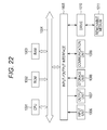
- Fig. 22 is a view illustrating a configuration example of a general personal computer.
- the personal computer includes a central processing unit (CPU) 1001. To the CPU 1001, an input/output interface 1005 is connected through a bus 1004. To the bus 1004, a read only memory (ROM) 1002 and a random access memory (RAM) 1003 are connected.
- CPU central processing unit
- ROM read only memory
- RAM random access memory
- a drive 1010 to read/write data is connected to a removable medium 1011 such as a magnetic disk (including flexible disk), optical disk (including compact disc-read only memory (CD-ROM) and digital versatile disc (DVD)), a magneto optical disk (including mini disc (MD)), or a semiconductor memory.
- a magnetic disk including flexible disk
- optical disk including compact disc-read only memory (CD-ROM) and digital versatile disc (DVD)
- DVD digital versatile disc
- MD magneto optical disk
- semiconductor memory a drive 1010 to read/write data is connected to a magnetic disk (including flexible disk), optical disk (including compact disc-read only memory (CD-ROM) and digital versatile disc (DVD)), a magneto optical disk (including mini disc (MD)), or a semiconductor memory.
- the program can be installed into the storage unit 1008 through the input/output interface 1005. Also, the program can be received in the communication unit 1009 through the wired or wireless transmission medium and can be installed into the storage unit 1008. In addition, the program can be previously installed into the ROM 1002 or the storage unit 1008.
- a system means an aggregation of a plurality of components (apparatus, module (part), and the like) and it is not necessary whether all components are in the same housing.
- a plurality of apparatuses housed in different housings and connected to each other through a network and one apparatus in which a plurality of modules is housed in one housing are systems.
- present technique may also include the following configuration.
Landscapes
- Engineering & Computer Science (AREA)
- Multimedia (AREA)
- Signal Processing (AREA)
- General Engineering & Computer Science (AREA)
- Computing Systems (AREA)
- Compression Or Coding Systems Of Tv Signals (AREA)
- Compression Of Band Width Or Redundancy In Fax (AREA)
Abstract
Description
- The present technique relates to an image sensor, a data transmission method thereof, an information processing apparatus, an information processing method, an electronic device, and a program. Specifically, the present invention relates to an image sensor, a data transmission method thereof, an information processing apparatus, an information processing method, an electronic device, and a program with which it becomes possible to transmit image data in a prescribed format without changing an existence interface for data transmission and to improve flexibility with respect to a compression method or connection with image processing large scale integration (LSI).
- In a device such as a digital camera, an image imaged by an image sensor is converted into compression data and is supplied through an interface to image processing LSI included in a digital signal processor (DSP) or the like.
- Incidentally, as a compression data method in which transmission is performed between an interface of the image sensor and that of the image processing LSI, for example, a method which is a combination of a differential pulse code modulation (DPCM) and a pulse code modulation (PCM) is employed. For example, with respect to an interface between chips for a mobile phone, a standard mobile imaging architecture (SMIA) standard is provided as a standard for compression data (see Non-Patent Document 1).
- Also, a method to compress an N bit signal into an n bit signal, to perform decomposition and connection thereof, and to perform an output as N bits is proposed (see Patent Document 1). A purpose is to shorten a pixel data output period by adjusting a data rate, which is reduced into n bits, to a data rate of N bits. That is, for example, 12-bit pixel data is compressed into eight bits and a next pixel is decomposed into four bits. Then, transmission as 12-bit data is performed.
- Non-Patent Document 1: SMIA 1.0 Part 1: Functional specification
- Patent Document 1: Japanese Patent Application Laid-Open No.
2011-049901 - However, in the SMIA standard, it is necessary to treat compressed data as RAW data of one pixel. Thus, in order to deal with various kinds of compression data, it is necessary to newly develop an RAW standard.
- Thus, in order to change a compression rate, it becomes necessary to change a format converter circuit in a LINK layer and to correct a packing circuit.
- Also, in a technique in
Patent Document 1, it is assumed that the number of bits of pixel data before compression and that during data transmission is identical. Thus, for example, it is difficult to set a compression rate in such a manner that 12-bit pixel data is converted into five bits and it is not possible to set a compression rate freely. In addition, a method for application to 8B10B transmission which corresponds to a clock data recovery method corresponding to high-speed transmission is not described. - The present technique has been provided in view of the forgoing. Specifically, the present technique makes it possible to set various compression rates while using an existing interface by converting a plurality of pieces of pixel data into a compression format of various numbers of pixels, performing conversion into a prescribed transmission format, and performing transmission.
- An image sensor of a first aspect of the present technique includes: an imaging unit configured to image an original image; a compression unit configured to compress a plurality of pieces of pixel data of the original image into a compression format; and a conversion unit configured to convert the compression format of the plurality of pieces of pixel data of the original image into a transmission format of the plurality of pieces of pixel data.
- A bit length of the transmission format may be different from a bit length of the compression format.
- The bit length of the transmission format may be identical to the bit length of the compression format.
- The compression unit may perform compression into the compression format in a unit of the plurality pieces of pixel data of the original image, and the conversion unit may convert the compression format which is compressed in the unit of the plurality of pieces of pixel data of the original image into the plurality of transmission formats.
- The conversion unit may arrange virtual data into pixel data processed in the unit of the plurality of pieces of pixel data for matching with a block size when converting the compression format which is compressed in the unit of the plurality of pieces of pixel data of the original image into the plurality of transmission formats.
- A setting unit configured to set the a compression rate according to image quality of the original image may be further included, wherein the compression unit may compress the plurality of pieces of pixel data of the original image into a compression format at the compression rate set by the setting unit.
- A data transmission method of the image sensor of the first aspect of the present technique includes the steps of: imaging an original image; compressing a plurality of pieces of pixel data of the original image into a compression format; and converting the compression format of the plurality of pieces of pixel data of the original image into a transmission format of the plurality of pieces of pixel data.
- A program of the first aspect of the present technique causes a computer to execute processing including an imaging step to image an original image, a compression step to compress a plurality of pieces of pixel data of the original image into a compression format, and a conversion step to convert the compression format of the plurality of pieces of pixel data of the original image into a transmission format of the plurality of pieces of pixel data.
- An information processing apparatus of a second aspect of the present technique includes: a decompression unit configured to decompress a transmission format of a plurality of pieces of pixel data of an original image, which format is converted from a compression format of the plurality of pieces of pixel data of the original image into which compression format the plurality of pieces of pixel data of the original image is compressed, into the compression format of the plurality of pieces of pixel data; and an expansion unit configured to expand the compression format decompressed by the decompression unit into the plurality of pieces of pixel data of the original image.
- A bit length of the transmission format may be different from a bit length of the compression format.
- The bit length of the transmission format may be identical to the bit length of the compression format.
- The decompression unit may decompress the plurality of transmission formats into the compression format in a unit of the plurality of pieces of pixel data of the original image, and the expansion unit may expand the compression format compressed in the unit of the plurality of pieces of pixel data of the original image into the plurality of pieces of pixel data.
- A setting unit configured to set a compression rate according to image quality of the original image may be further included, wherein the expansion unit may expand the compression format into the plurality of pieces of pixel data of the original image based on the compression rate set by the setting unit.
- An information processing method of the second aspect of the present technique includes the steps of: decompressing a transmission format of a plurality of pieces of pixel data of an original image, which format is converted from a compression format of the plurality of pieces of pixel data of the original image into which compression format the plurality of pieces of pixel data of the original image is compressed, into the compression format of the plurality of pieces of pixel data; and expanding the decompressed compression format into the plurality of pieces of pixel data of the original image.
- A program of the second aspect of the present technique causes a computer to execute processing including a decompression step to decompress a transmission format of a plurality of pieces of pixel data of an original image, which format is converted from a compression format of the plurality of pieces of pixel data of the original image into which compression format the plurality of pieces of pixel data of the original image is compressed, into the compression format of the plurality of pieces of pixel data, and an expansion step to expand the compression format, which is decompressed by the processing in the decompression step, into the plurality of pieces of pixel data of the original image.
- An electronic device of the third aspect of the present technique includes: an imaging unit configured to image an original image; a compression unit configured to compress a plurality of pieces of pixel data of the original image into a compression format; and a conversion unit configured to convert the compression format of the plurality of pieces of pixel data of the original image into a transmission format of the plurality of pieces of pixel data.
- An electronic device of the fourth aspect of the present technique includes: a decompression unit configured to decompress a transmission format of a plurality of pieces of pixel data of an original image, which format is converted from a compression format of the plurality of pieces of pixel data of the original image into which compression format the plurality of pieces of pixel data of the original image is compressed, into the compression format of the plurality of pieces of pixel data, and an expansion unit configured to expand the compression format decompressed by the decompression unit into the plurality of pieces of pixel data of the original image.
- In the first and third aspects of the present technique, an original image is imaged, a plurality of pieces of pixel data of the original image is compressed into a compression format, and the compression format of the plurality of pieces of pixel data of the original image is converted into a transmission format of the plurality of pieces of pixel data.
- In the second and fourth aspects of the present technique, the transmission format of the plurality of pieces of pixel data, which format is converted from the compression format of the plurality of pieces of pixel data of the original image into which compression format the plurality of pieces of pixel data of the original image is compressed, is decompressed into the compression format of the plurality of pieces of pixel data, and the decompressed compression format is expanded into the plurality of pieces of pixel data of the original image.
- Each of the image sensor and the electronic device of the first to fourth aspects of the present technique may be an independent apparatus or electronic device or may be a block to perform each processing.
- According to the first to fourth aspects of the present technique, it becomes possible to transmit image data in a prescribed format without making a change in an existence interface of data transmission and to increase flexibility with respect to a compression rate or connection with various types of image processing LSI.
-
-
Fig. 1 is a view illustrating a first configuration example of a transmission system. -
Fig. 2 is a second configuration example of the transmission system. -
Fig. 3 is a view illustrating a third configuration example of the transmission system. -
Fig. 4 is a view illustrating an example of a frame format. -
Fig. 5 is a view illustrating a configuration example of each of a transmission unit and a reception unit. -
Fig. 6 is a view illustrating a header structure. -
Fig. 7 is a view illustrating contents and an information amount of header information. -
Fig. 8 is a view illustrating an example of a bit array. -
Fig. 9 is a flowchart for describing processing in an imaging apparatus. -
Fig. 10 is a flowchart for describing data transmission processing performed in step S2 inFig. 9 . -
Fig. 11 is a view for describing an example of performing data transmission processing and data reception processing by converting a 12-bit original image data format into a six-bit compression data format. -
Fig. 12 is a flowchart for describing data reception processing performed in step S3 inFig. 9 . -
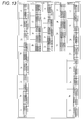
Fig. 13 is a view for describing an example of performing data transmission processing and data reception processing by converting a 12-bit original image data format into a five-bit compression data format. -
Fig. 14 is a view for describing a first example of performing data transmission processing and data reception processing by converting a 12-bit original image data format into a four-bit compression data format. -
Fig. 15 is a view for describing a second example of performing data transmission processing and data reception processing by converting a 12-bit original image data format into a four-bit compression data format. -
Fig. 16 is a view for describing an example of performing data transmission processing and data reception processing by converting a 10-bit original image data format into a six-bit compression data format. -
Fig. 17 is a view for describing an example of performing data transmission processing and data reception processing by converting a 10-bit original image data format into a five-bit compression data format. -
Fig. 18 is a view for describing an example of performing data transmission processing and data reception processing by converting a 12-bit original image data format of 32 pixels into a compression data format of 16 pixels which format includes a configuration identical to that of the 12-bit original image data format. -
Fig. 19 is a view for describing an example of performing data transmission processing and data reception processing by converting a 12-bit original image data format of 32 pixels into a compression data format of 16 pixels which format includes a configuration identical to that of the 12-bit original image data format. -
Fig. 20 is a view for describing an example of performing data transmission processing and data reception processing by converting a 12-bit original image data format of 32 pixels into a compression data format of 16 pixels which format includes a configuration identical to that of the 12-bit original image data format. -
Fig. 21 is a view for describing setting processing to set the number of bits of an original image data format and a compression rate thereof. -
Fig. 22 is a view for describing a configuration example of a general personal computer. - First, with reference to
Fig. 1 , a first configuration example of a transmission system according to an embodiment of the present invention will be described. - A
transmission system 1 inFig. 1 includes animage sensor 11 and aDSP 12. Theimage sensor 11 and theDSP 12 respectively include large scale integrated circuits (LSI) which are different from each other. Theimage sensor 11 and theDSP 12 are provided in an imaging apparatus, which includes an imaging function, such as a digital camera or a mobile function. To theimage sensor 11, animaging unit 21 and atransmission unit 22 are provided. To theDSP 12, areception unit 31 and animage processing unit 32 are provided. - The
imaging unit 21 of theimage sensor 11 includes an imaging element such as a complementary metal oxide semiconductor (CMOS) and performs photoelectric conversion of light received through a lens. Also, theimaging unit 21 performs A/D conversion or the like of a signal acquired by the photoelectric conversion and serially outputs pixel data included in an image in one frame to thetransmission unit 22 by data in one pixel. - The
transmission unit 22 assigns, to a plurality of transmission paths, the data of each pixel which data is supplied by theimaging unit 21, for example, in an order supplied by theimaging unit 21 and transmits the data to theDSP 12 in parallel through the plurality of transmission paths. In an example inFig. 1 , transmission of the pixel data is performed by using eight transmission paths. A transmission path between theimage sensor 11 and theDSP 12 may be a wired transmission path or a wireless transmission path. In the following, the transmission path between theimage sensor 11 and theDSP 12 is arbitrarily referred to as a Lane. - The
reception unit 31 of theDSP 12 receives pixel data transmitted from thetransmission unit 22 through the eight Lanes and serially outputs the data of each pixel to theimage processing unit 32. - Based on the pixel data supplied by the
reception unit 31, theimage processing unit 32 generates an image in one frame and performs various kinds of image processing by using the generated image. The image data transmitted from theimage sensor 11 to theDSP 12 is RAW data. In theimage processing unit 32, various kinds of processing such as compression of image data, display of an image, or recording of image data into a recording medium is performed. - Next, with reference to
Fig. 2 , a second configuration example of thetransmission system 1 will be described. To a configuration which is illustrated inFig. 2 and which is identical to the configuration illustrated inFig. 1 , the same reference sign is assigned. An Overlap description is arbitrarily omitted. - To an
image sensor 11 of thetransmission system 1 inFig. 2 , animaging unit 21 and two transmission units 22-1 and 22-2 are provided. To aDSP 12, two reception units 31-1 and 31-2 and animage processing unit 32 are provided. - The
imaging unit 21 outputs pixel data, which is included in an image in one frame acquired by imaging, in parallel to the transmission unit 22-1 and the transmission unit 22-2 by data of one pixel. For example, theimaging unit 21 outputs data of a pixel in an odd line to the transmission unit 22-1 and outputs data of a pixel in an even line to the transmission unit 22-2. - The transmission unit 22-1 assigns, to a plurality of Lanes, the data of each pixel which data is supplied by the
imaging unit 21, for example, in an order supplied by theimaging unit 21 and transmits the data to theDSP 12 in parallel through the plurality of Lanes. Similarly, the transmission unit 22-2 assigns, to a plurality of Lanes, the data of each pixel which data is supplied by theimaging unit 21, for example, in an order supplied by theimaging unit 21 and transmits the data to theDSP 12 in parallel through the plurality of Lanes. - In the example in
Fig. 2 , theimage sensor 11 and theDSP 12 are also connected to each other through eight Lanes. Each of the transmission unit 22-1 and the transmission unit 22-2 transmits pixel data by using four Lanes. - The reception unit 31-1 of the
DSP 12 receives pixel data transmitted from the transmission unit 22-1 through the four Lanes and serially outputs data of each pixel to theimage processing unit 32. Similarly, the reception unit 31-2 receives pixel data transmitted from the transmission unit 22-2 through the four Lanes and serially outputs data of each pixel to theimage processing unit 32. - Based on the pixel data supplied by the reception unit 31-1 and the pixel data supplied by the reception unit 31-2, the
image processing unit 32 generates an image in one frame and performs various kinds of image processing by using the generated image. - As illustrated in
Fig. 2 , two transmission units are provided in theimage sensor 11 and two reception units are provided in theDSP 12 correspondingly. Thus, even when a transmission rate of the pixel data output from theimaging unit 21 is high, it becomes possible to transmit the pixel data to theDSP 12. - Next, with reference to
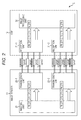
Fig. 3 , a third configuration example of thetransmission system 1 will be described. To a configuration which is illustrated inFig. 3 and which is identical to the configuration illustrated inFig. 1 , the same reference sign is assigned. An Overlap description is arbitrarily omitted. - To the
transmission system 1 inFig. 3 , two image sensors which are an image sensor 11-1 and an image sensor 11-2 are provided. To the image sensor 11-1, an imaging unit 21-1 and a transmission unit 22-1 is provided. To the image sensor 11-2, an imaging unit 21-2 and a transmission unit 22-2 are provided. Similarly to the case inFig. 2 , to theDSP 12, two reception units 31-1 and 31-2 and animage processing unit 32 are provided. - The imaging unit 21-1 of the image sensor 11-1 serially outputs pixel data, which is included in an image in one frame which image is acquired by imaging, by data of one pixel to the transmission unit 22-1.
- The transmission unit 22-1 assigns, to a plurality of Lanes, the data of each pixel which data is supplied by the imaging unit 21-1, for example, in an order supplied by the imaging unit 21-1 and transmits the data to the
DSP 12 in parallel through the plurality of Lanes. - The imaging unit 21-2 of the image sensor 11-2 serially outputs pixel data, which is included in an image in one frame which image is acquired by imaging, by data of one pixel to the transmission unit 22-2.
- The transmission unit 22-2 assigns, to a plurality of Lanes, the data of each pixel which data is supplied by the imaging unit 21-2, for example, in an order supplied by the imaging unit 21-2 and transmits the data to the
DSP 12 in parallel through the plurality of Lanes. - In the example in
Fig. 3 , a side of the image sensor and theDSP 12 are also connected to each other through eight Lanes. Four Lanes are assigned to each of the image sensor 11-1 and the image sensor 11-2. Each of the transmission unit 22-1 and the transmission unit 22-2 transmits pixel data by using four Lanes. - The reception unit 31-1 of the
DSP 12 receives the pixel data transmitted from the transmission unit 22-1 of the image sensor 11-1 through the four Lanes and serially outputs data of each pixel to theimage processing unit 32. Similarly, the reception unit 31-2 receives the pixel data transmitted from the transmission unit 22-2 of the image sensor 11-2 through the four Lanes and serially outputs data of each pixel to theimage processing unit 32. - The
image processing unit 32 generates an image in one frame based on the pixel data supplied by the reception unit 31-1 and generates an image in one frame based on the pixel data supplied by the reception unit 31-2. Theimage processing unit 32 performs various kinds of image processing by using the generated image. - As illustrated in
Fig. 3 , by providing two image sensors, for example, it becomes possible to process, with oneDSP 12, a 3D image including a left-eye image imaged by the image sensor 11-1 and a right-eye image imaged by the image sensor 11-2. There is a parallax between the left-eye image and the right-eye image. - As described above, to the image sensor in the
transmission system 1, one or more transmission units to transmit imaged image data in one frame are provided. On the other hand, to the DSP, one or more reception units to receive data transmitted from the image sensor are provided corresponding to the transmission units of the image sensor. - In the following, data transmission in the
transmission system 1 inFig. 1 in which system one transmission unit is provided in theimage sensor 11 and one reception unit is provided in theDSP 12 will be described. Data transmission is performed similarly between the transmission unit 22-1 and the reception unit 31-1 and between the transmission unit 22-2 and the reception unit 31-2 which are inFig. 2 andFig. 3 . - Next, with reference to
Fig. 4 , an example of a format used to transmit image data in one frame between theimage sensor 11 and theDSP 12 will be described. - An effective pixel region A1 is a region of an effective pixel of the image in one frame which image is imaged by the
imaging unit 21. On a left side of the effective pixel region A1, a margin region A2 is set, the number of pixels in a vertical direction thereof being identical to the number of pixels in a vertical direction of the effective pixel region A1. - On an upper side of the effective pixel region A1, a front dummy region A3 is set, the number of pixels in a horizontal direction thereof being identical to the total number of pixels in a horizontal direction of the effective pixel region A1 and the margin region A2. In the example in
Fig. 4 , Embedded Data is inserted into the front dummy region A3. The Embedded Data includes information of a set value, which is related to imaging by theimaging unit 21, such as a shutter speed, an aperture value, or gain. There is a case where the Embedded Data is inserted into a rear dummy region A4. - On a lower side of the effective pixel region A1, the rear dummy region A4 is set, the number of pixels in a horizontal direction thereof being identical to the total number of pixels in the horizontal direction of the effective pixel region A1 and the margin region A2.
- An image data region A11 includes the effective pixel region A1, the margin region A2, the front dummy region A3, and the rear dummy region A4.
- A header is added in front of each line included in the image data region A11 and a Start Code is added in front of the header. Also, a footer is optionally added behind each line included in the image data region A11 and a control code, which will be described later, such as an End Code is added behind the footer. When the footer is not added, the control code such as the End Code is added behind each line included in the image data region A11.
- Each time an image in one frame which image is imaged by the
imaging unit 21 is transmitted from theimage sensor 11 to theDSP 12, whole data in a format illustrated inFig. 4 is transmitted as transmission data. - A band on an upper side in
Fig. 4 illustrates a structure of a packet used for transmission of transmission data illustrated in a lower side thereof. When it is assumed that a sequence of pixels in a horizontal direction is a line, in a payload of a packet, data of the pixel in one line of the image data region A11 is stored. Transmission of the whole image data in one frame is performed by using packets more than the number of pixels in the vertical direction of the image data region A11. - When a header and a footer are added to the payload which stores the pixel data in one line, one packet is configured. As described later, the header includes additional information, such as a Frame Start, a Frame End, Line Valid, a Line Number, or an ECC, of the pixel data stored in the payload. To each packet, at least a Start Code and an End Code, which are control codes, are added.
- In such manner, by employing a format to transmit pixel data in an image in one frame by each line, it becomes possible to transmit additional information such as a header or a control code such as a Start Code or an End Code during a blanking period of each line.
- Next, with reference to
Fig. 5 , a configuration example of each of thetransmission unit 22 and thereception unit 31 will be described. - A configuration illustrated by being surrounded by a broken line on a left side in
Fig. 5 is a configuration of thetransmission unit 22 and a configuration illustrated by being surrounded by a broken line on a right side is a configuration of thereception unit 31. Each of thetransmission unit 22 and thereception unit 31 includes a configuration of a link layer and a configuration of a physical layer. A configuration illustrated on an upper side of a solid line L2 is a configuration of the link layer and a configuration illustrated on a lower side of the solid line L2 is a configuration of the physical layer. - Note that a configuration illustrated on an upper side of a solid line L1 is a configuration of an application layer. A
system control unit 51, a framedata input unit 52, aregister 53, and acompression unit 54 are realized in theimaging unit 21. Thesystem control unit 51 performs communication with a LINK-TXprotocol management unit 61 of thetransmission unit 22 and controls transmission of image data, for example, by providing information related to a frame format. The framedata input unit 52 performs imaging according to a command by a user or the like and supplies data of each pixel included in an image acquired by performance of the imaging to aconversion unit 62 of thetransmission unit 22 through thecompression unit 54. Thecompression unit 54 compresses the number of bits of the data of each pixel into the predetermined number of bits and supplies the compressed data of the pixel to theconversion unit 62 of thetransmission unit 22. Theregister 53 stores information such as a compression rate in thecompression unit 54, the number of bits of conversion in theconversion unit 62, and the number of Lanes. Transmission processing of image data compressed according to the information stored in theregister 53 is performed. - Also, a frame
data output unit 141, aregister 142, asystem control unit 143, and anexpansion unit 144 in the configuration of the application layer are realized in theimage processing unit 32. Based on pixel data which is pixel data of each line supplied by thereception unit 31 and which is expanded by theexpansion unit 144, the framedata output unit 141 generates and outputs an image in one frame. By using the image output from the framedata output unit 141, various kinds of processing is performed. Theregister 142 stores various set values related to reception of image data such as an expansion rate in theexpansion unit 144, the number of bits of conversion in aconversion unit 125, and the number of Lanes. Reception processing of image data is performed according to the information stored in theregister 142. Thesystem control unit 143 performs communication with a LINK-RXprotocol management unit 121 and controls a sequence such as a mode change. - The
expansion unit 144 expands pixel data in each line according to a compression rate in thecompression unit 54. Also, thesystem control unit 51 of theimage sensor 11 and thesystem control unit 143 of theDSP 12 transmit/receive information, which is stored in theregister 53, such as a compression rate in thecompression unit 54, a compression rate to which theexpansion unit 144 corresponds, the number of bits of conversion in each of theconversion units registers system control unit 143 of theDSP 12 receives information such as the number of bits of the original image data format or the number of bits of the compression data format and sets a compression rate to be set with respect to thesystem control unit 51 of theimage sensor 11 and a conversion rate in each of theconversion units system control unit 143 sets a compression rate according to an imaging condition. That is, in a case of performing imaging with high sensitivity by international organization for standardization (ISO) sensitivity of the imaging by theimaging unit 21, an influence by a noise is received easily, and thus, thesystem control unit 143 performs setting in such a manner that a compression rate of the pixel data format becomes low. Inversely, in a case of low sensitivity, an influence of the noise is small, and thus, thesystem control unit 143 sets a high compression rate. - First, a configuration of a link layer of the
transmission unit 22 will be described. - To the
transmission unit 22, a LINK-TXprotocol management unit 61, aconversion unit 62, a payloadECC insertion unit 63, apacket generation unit 64, and aLane distribution unit 65 are provided as a configuration of the link layer. The LINK-TXprotocol management unit 61 includes astate control unit 71, aheader generation unit 72, adata insertion unit 73, and afooter generation unit 74. - The
state control unit 71 of the LINK-TXprotocol management unit 61 manages a state of the link layer of thetransmission unit 22. - The
header generation unit 72 generates a header to be added to a payload storing pixel data in one line and outputs the generated header to thepacket generation unit 64. -
Fig. 6 is a view illustrating a structure of the header generated by theheader generation unit 72. - As described above, the whole one packet includes a header and payload data which is pixel data in one line. There is a case where a footer is added to the packet. The header includes header information and a Header ECC.
- The header information includes a Frame Start, a Frame End, Line Valid, a Line Number, and Reserved. Contents and an information amount of each piece of information are illustrated in
Fig. 7 . - The Frame Start is one-bit information indicating a head of the frame. In a Frame Start of a header of a packet used for transmission of pixel data in a first line in the image data region A11 in
Fig. 4 , a value of 1 is set. In a Frame Start of a header of a packet used for transmission of pixel data in each of the other lines, a value of 0 is set. - The Frame End is one-bit information indicating an end of the frame. In a Frame End of a header of a packet including, in a payload, pixel data in an end line in the effective pixel region A1, a value of 1 is set. In a Frame End of a header of a packet used for transmission of pixel data in each of the other lines, a value of 0 is set.
- The Frame Start and the Frame End are frame information which is information related to a frame.
- The Line Valid is one-bit information indicating whether a line of pixel data stored in a payload is a line of an effective pixel. In Line Valid of a header of a packet used for transmission of pixel data in a line in the effective pixel region A1, a value of 1 is set. In Line Valid of a header of a packet used for transmission of pixel data in each of the other lines, a value of 0 is set.
- The Line Number is 13-bit information indicating a line number of a line including pixel data stored in a payload.
- The Line Valid and the Line Number are line information which is information related to a line.
- The Reserved is a 32-bit region for expansion. A data amount of the whole header information is six bytes.
- As illustrated in
Fig. 6 , in a Header ECC arranged next to the header information, a cyclic redundancy check (CRC) code which is a two-byte error detection code calculated based on six-byte header information is included. Also, in the Header ECC, two pieces of information each of which is identical to eight-byte information which information is a pair of header information and a CRC code are included next to the CRC code. - That is, in a header of one packet, three same pairs of header information and a CRC code are included. A data amount of the whole header is 24 bytes which is the total of eight bytes of the first pair of header information and a CRC code, eight bytes of the second pair of header information and a CRC code, and eight bytes of the third pair of header information and a CRC code.
-
Fig. 8 is a view illustrating an example of an eight-byte bit array which configures a pair of header information and a CRC code. - In a byte H7 which is the first one byte of eight bytes which configures a header, one bit of each of the Frame Start, the Frame End, and the Line Valid and first to fifth bits of 13 bits of the Line Number are serially included from the first bit. Also, in a byte H6 which is the second one byte, sixth to 13th bits of 13 bits of the Line Number are included.
- From a byte H5 which is the third one byte to a byte H2 which is the sixth one byte are the Reserved. In a byte H1 which is the seventh one byte and in a byte H0 which is the eighth one byte, each bit of the CRC code is included.
- Referring back to description of
Fig. 5 , theheader generation unit 72 generates header information according to control by thesystem control unit 51. For example, from thesystem control unit 51, information indicating a line number of pixel data output from the framedata input unit 52 or information indicating a head and an end of a frame is supplied. - Also, the
header generation unit 72 applies the header information to a generator polynomial and calculates a CRC code. A generator polynomial of a CRC code which generator polynomial is applied to the header information is expressed, for example, by the following formula (1).
[Mathematical Formula 1]
- The
header generation unit 72 generates a pair of header information and a CRC code by adding the CRC code to the header information. By repeatedly arranging the same pair of header information and a CRC code for three times, theheader generation unit 72 generates a header. Theheader generation unit 72 outputs the generated header to thepacket generation unit 64. - The
data insertion unit 73 generates data used for stuffing and outputs the generated data to theconversion unit 62 and theLane distribution unit 65. Payload stuffing data which is the stuffing data supplied to theconversion unit 62 is added to pixel data converted by theconversion unit 62 and is used for adjustment of an amount of pixel data stored in a payload. Also, Lane stuffing data which is the stuffing data supplied to theLane distribution unit 65 is added to Lane-assigned data and is used for adjustment of a data amount between Lanes. - According to control by the
system control unit 51, thefooter generation unit 74 arbitrarily applies payload data to a generator polynomial and calculates a 32-bit CRC code. Then, thefooter generation unit 74 outputs the calculated CRC code as a footer to thepacket generation unit 64. A generator polynomial of the CRC code added as a footer is expressed, for example, by the following formula (2).
[Mathematical Formula 2]
- The
conversion unit 62 acquires compression data which is the pixel data supplied by the framedata input unit 52 and which is compressed by thecompression unit 54 and converts compression data of each pixel into data in a one-byte unit. For example, compression data of a pixel value (RGB) of each pixel of an image imaged by theimaging unit 21 is expressed by the number of bits which is any of eight bits, 10 bits, 12 bits, 14 bits, and 16 bits. - The
conversion unit 62 inFig. 5 serially performs such conversion with respect to each pixel, for example, from a pixel on a left end of a line. Also, theconversion unit 62 generates payload data by adding the payload stuffing data supplied by thedata insertion unit 73 to compression data in a byte-unit which data is acquired by conversion and outputs the generated payload data to the payloadECC insertion unit 63. - The compression data converted by the
conversion unit 62 is grouped into the predetermined number of groups in an order acquired by the conversion. - In the link layer of the
transmission unit 22, after grouping is performed in such a manner, processing is performed in parallel with respect to compression data at the same place in each group in each period prescribed by a clock signal. - As described above, in a payload of one packet, compression data corresponding to pixel data in one line is included.
- After the compression data corresponding to the pixel data in one line is grouped, payload stuffing data is added in such a manner that a data length of each group becomes identical. The payload stuffing data is one-byte data.
- Based on the payload data supplied by the
conversion unit 62, the payloadECC insertion unit 63 calculates an error correction code used for error correction of payload data and inserts parity which is the calculated error correction code into the payload data. As an error correction code, for example, a Reed-Solomon code is used. Note that insertion of the error correction code is optional. For example, only one of insertion of parity performed by the payloadECC insertion unit 63 and adding of a footer performed by thefooter generation unit 74 can be performed. - The payload
ECC insertion unit 63 outputs payload data into which the parity is inserted to thepacket generation unit 64. When insertion of the parity is not performed, the payload data supplied by theconversion unit 62 to the payloadECC insertion unit 63 is output to thepacket generation unit 64 as it is. - The
packet generation unit 64 generates a packet by adding the header generated by theheader generation unit 72 to the payload data supplied by the payloadECC insertion unit 63. When generation of a footer is performed by thefooter generation unit 74, thepacket generation unit 64 also adds the footer to the payload data. - The
packet generation unit 64 outputs packet data which is data included in the generated one packet to theLane distribution unit 65. With respect to theLane distribution unit 65, packet data including header data and payload data, packet data including header data, payload data, and footer data, or packet data including header data and payload data into which parity is inserted is supplied. A packet structure inFig. 6 is logical. In the link layer and the physical layer, data of a packet including the structure inFig. 6 is processed in a byte-unit. - The
Lane distribution unit 65 assigns the packet data, which is data supplied by thepacket generation unit 64, to each Lane used for data transmission amongLanes 0 to 7 in an order from data at a head. - The
Lane distribution unit 65 outputs, to the physical layer, the packet data assigned to each Lane in such a manner. In the following, a case where data is transmitted by using eight Lanes of theLanes 0 to 7 will be mainly described. However, even in a case where the number of Lanes used for data transmission is a different number, similar processing is performed. - Next, a configuration of a physical layer of the
transmission unit 22 will be described. - To the
transmission unit 22, a PHY-TXstate control unit 81, aclock generation unit 82, signal processing units 83-0 to 83-N are provided as a configuration of the physical layer. The signal processing unit 83-0 includes a controlcode insertion unit 91, an8B10B symbol encoder 92, asynchronization unit 93, and atransmission unit 94. Packet data output from theLane distribution unit 65 and assigned to theLane 0 is input into the signal processing unit 83-0 and packet data assigned to theLane 1 is input into the signal processing unit 83-1. Also, packet data assigned to a Lane N is input into the signal processing unit 83-N. - In such a manner, in the physical layer of the
transmission unit 22, the signal processing units 83-0 to 83-N are provided, the number thereof being the same with the number of Lanes. Processing of packet data transmitted by using each Lane is performed in parallel in the signal processing units 83-0 to 83-N. A configuration of the signal processing unit 83-0 will be described. Each of the signal processing units 83-1 to 83-N includes a similar configuration. - The PHY-TX
state control unit 81 controls each unit of the signal processing units 83-0 to 83-N. For example, timing of each kind of processing performed by the signal processing units 83-0 to 83-N is controlled by the PHY-TXstate control unit 81. - The
clock generation unit 82 generates a clock signal and outputs the generated clock signal to asynchronization unit 93 of each of the signal processing units 83-0 to 83-N. - The control
code insertion unit 91 of the signal processing unit 83-0 adds a control code to the packet data supplied by theLane distribution unit 65. A control code is a code expressed by one symbol selected from a previously-prepared plurality of kinds of symbols or a combination of a plurality of kinds of symbols. Each symbol inserted by the controlcode insertion unit 91 is eight-bit data. 8B10B conversion is performed in a circuit in the following stage, whereby, one symbol inserted by the controlcode insertion unit 91 becomes 10-bit data. On the other hand, as described later, 10B8B conversion is performed with respect to reception data in thereception unit 31. Each symbol before the 10B8B conversion which symbol is included in the reception data is 10-bit data and each symbol after the 10B8B conversion is eight-bit data. - As a control code, there are an Idle Code, a Start Code, an End Code, a Pad Code, an Sync Code, a Deskew Code, and an Standby Code.
- The Idle Code is a symbol group repeatedly transmitted in a period other than transmission of packet data. The Idle Code is expressed by D00.0 (00000000) of a D Character which is an 8B10B Code.
- The Start Code is a symbol group indicating a start of a packet. As described above, the Start Code is added in front of the packet. The Start Code is expressed by four symbols of K28.5, K27.7, K28.2, and K27.7 which are in a combination of three kinds of K Characters.
- The End Code is a symbol group indicating an end of a packet. As described above, the End Code is added behind the packet. The End Code is expressed by four symbols of K28.5, K29.7, K30.7, and K29.7 which are in a combination of three kinds of K Characters.
- The Pad Code is a symbol group inserted into payload data in order to fill a gap between a pixel data band and a PHY transmission band. The pixel data band is a transmission rate of compressed pixel data output from the
imaging unit 21 and input into thetransmission unit 22 and the PHY transmission band is a transmission rate of compressed pixel data transmitted from thetransmission unit 22 and input into thereception unit 31. The Pad Code is four symbols of K23.7, K28.4, K28.6, and K28.7 which are in a combination of four kinds of K Characters. - Insertion of the Pad Code into the payload data assigned to the
Lane 0 is performed by the controlcode insertion unit 91 of the signal processing unit 83-0. Similarly, insertion of the Pad Code into payload data assigned to a different Lane is performed at the same timing by each of the signal processing units 83-1 to 83-N. The number of Pad Codes is determined based on a gap between the pixel data band and the PHY transmission band, a frequency of a clock signal generated by theclock generation unit 82, or the like. - In such a manner, when the pixel data band is narrow and the PHY transmission band is wide, the Pad Code is inserted to adjust a gap between the both bands. For example, since the Pad Code is inserted, adjustment is performed in such a manner that the gap between the pixel data band and the PHY transmission band fits in a certain range.
- The Sync Code is a symbol group used to secure bit synchronization and symbol synchronization between the
transmission unit 22 and thereception unit 31. The Sync Code is expressed by two symbols which are K28.5 and Any**. Any** indicates that any kind of symbol may be used. The Sync Code is repeatedly transmitted, for example, in a training mode before transmission of packet data is started between thetransmission unit 22 and thereception unit 31. - The Deskew Code is a symbol group used for correction of Data Skew between Lanes, that is, a gap in reception timing of data received in each Lane of the
reception unit 31. The Deskew Code is expressed by two symbols which are K28.5 and Any**. Correction of Data Skew between Lanes by using the Deskew Code will be described later. - The Standby Code is a symbol group used to notify the
reception unit 31 that an output from thetransmission unit 22 becomes a state such as High-Z (high impedance) and data transmission is not performed any more. That is, the Standby Code is transmitted to thereception unit 31 when the transmission of the packet data is ended and a state becomes a Standby state. The Standby Code is expressed by two symbols which are K28.5 and Any**. - The control
code insertion unit 91 outputs, to the8B10B symbol encoder 92, packet data to which such a control code is added. - The
8B10B symbol encoder 92 performs the 8B10B conversion with respect to the packet data (packet data to which control code is added) supplied by the controlcode insertion unit 91 and outputs, to thesynchronization unit 93, packet data converted into data in a 10-bit unit. - The
synchronization unit 93 outputs each bit of the packet data, which is supplied by the8B10B symbol encoder 92, to thetransmission unit 94 according to the clock signal generated by theclock generation unit 82. - The
transmission unit 94 transmits the packet data, which is supplied by thesynchronization unit 93, to thereception unit 31 through a transmission path included in theLane 0. In a case of performing data transmission by using eight Lanes, packet data is also transmitted to thereception unit 31 by using transmission paths included in theLanes 1 to 7. - Next, a configuration of a physical layer of the
reception unit 31 will be described. - To the
reception unit 31, a PHY-RXstate control unit 101 and signal processing units 102-0 to 102-N are provided as a configuration of the physical layer. The signal processing unit 102-0 includes areception unit 111, aclock generation unit 112, asynchronization unit 113, asymbol synchronization unit 114, a10B8B symbol decoder 115, askew correction unit 116, and a controlcode removing unit 117. Packet data transmitted through a transmission path included in theLane 0 is input into the signal processing unit 102-0 and packet data transmitted through a transmission path included in theLane 1 is input into the signal processing unit 102-1. Also, packet data transmitted through a transmission path included in the Lane N is input into the signal processing unit 102-N. - In such a manner, in the physical layer of the
reception unit 31, the signal processing units 102-0 to 102-N are provided, the number thereof being the same with the number of Lanes. Processing of packet data transmitted by using each Lane is performed in parallel in the signal processing units 102-0 to 102-N. A configuration of the signal processing unit 102-0 will be described. Each of the signal processing units 102-1 to 102-N includes a similar configuration. - The
reception unit 111 receives a signal indicating the packet data transmitted from thetransmission unit 22 through the transmission path included in theLane 0 and outputs the signal to theclock generation unit 112. - By detecting an edge of the signal supplied by the
reception unit 111, theclock generation unit 112 performs bit synchronization and generates a clock signal based on a detection cycle of the edge. Theclock generation unit 112 outputs the signal, which is supplied by thereception unit 111, to thesynchronization unit 113 along with the clock signal. - According to the clock signal generated by the
clock generation unit 112, thesynchronization unit 113 performs sampling of the signal received in thereception unit 111 and outputs packet data acquired by the sampling to thesymbol synchronization unit 114. A function of clock data recovery (CDR) is realized by theclock generation unit 112 and thesynchronization unit 113. - By detecting a control code included in the packet data or by detecting a part of a symbol included in the control code, the
symbol synchronization unit 114 performs symbol synchronization. For example, thesymbol synchronization unit 114 detects a symbol of K28.5 included in each of the Start Code, the End Code, and the Deskew Code and performs the symbol synchronization. Thesymbol synchronization unit 114 outputs packet data which indicates each symbol and which is in a 10-bit unit to the10B8B symbol decoder 115. - Also, by detecting a boundary of a symbol included in the Sync Code repeatedly transmitted from the
transmission unit 22 in the training mode before the transmission of the packet data is started, thesymbol synchronization unit 114 performs the symbol synchronization. - The
10B8B symbol decoder 115 performs the 10B8B conversion with respect to the packet data in a 10-bit unit which data is supplied by thesymbol synchronization unit 114 and outputs packet data converted into data in an eight-bit unit to theskew correction unit 116. - The
skew correction unit 116 detects the Deskew Code from the packet data supplied by the10B8B symbol decoder 115. Information of detection timing of the Deskew Code which detection is performed by theskew correction unit 116 is supplied to the PHY-RXstate control unit 101. - Also, the
skew correction unit 116 corrects the Data Skew between Lanes in such a manner that timing of the Deskew Code matches timing indicated by the information supplied by the PHY-RXstate control unit 101. By the PHY-RXstate control unit 101, information indicating the latest timing in timing of the Deskew Code detected in each of the signal processing units 102-0 to 102-N is supplied. - Similar processing is performed in each of the signal processing units 102-1 to 102-N, whereby the Data Skew between the Lanes is corrected.
- The
skew correction unit 116 outputs packet data, in which the Data Skew is corrected, to the controlcode removing unit 117. - The control
code removing unit 117 removes the control code added to the packet data and outputs, as packet data, data from the Start Code to the End Code to the link layer. - The PHY-RX
state control unit 101 controls each unit of the signal processing units 102-0 to 102-N and performs, for example, correction of Data Skew between Lanes. Also, when an transmission error is caused in a predetermined Lane and a control code is lost, the PHY-RXstate control unit 101 performs error correction of the control code by adding a control code, which is transmitted in a different Lane, instead of the lost control code. - Next, a configuration of a link layer of the
reception unit 31 will be described. - To the
reception unit 31, a LINK-RXprotocol management unit 121, aLane integration unit 122, apacket separation unit 123, a payloaderror correction unit 124, and aconversion unit 125 are provided as a configuration of the link layer. The LINK-RXprotocol management unit 121 includes astate management unit 131, a headererror correction unit 132, adata removing unit 133, and a footererror detection unit 134. - The
Lane integration unit 122 performs integration by sorting pieces of packet data, which is supplied by the signal processing units 102-0 to 102-N in the physical layer, in an opposite order of an order of distribution to each Lane by theLane distribution unit 65 of thetransmission unit 22. - The
packet separation unit 123 separates the packet data of one packet, which data is integrated by theLane integration unit 122, into packet data included in header data and packet data included in payload data. Thepacket separation unit 123 outputs the header data to the headererror correction unit 132 and outputs the payload data to the payloaderror correction unit 124. - Also, when a footer is included in the packet, the
packet separation unit 123 separates data of one packet into packet data included in header data, packet data included in payload data, and packet data included in footer data. Thepacket separation unit 123 outputs the header data to the headererror correction unit 132 and outputs the payload data to the payloaderror correction unit 124. Also, thepacket separation unit 123 outputs the footer data to the footererror detection unit 134. - When parity is inserted into the payload data supplied by the
packet separation unit 123, the payloaderror correction unit 124 detects an error in the payload data and corrects the detected error by performing error correction calculation based on the parity. - The payload
error correction unit 124 outputs, to theconversion unit 125, compression data of the pixel data after the error correction which data is acquired by error correction on each of a Basic Block and an Extra Block. When parity is not inserted into the payload data supplied by thepacket separation unit 123, the payload data supplied by thepacket separation unit 123 is output to theconversion unit 125 as it is. - According to control by the
data removing unit 133, theconversion unit 125 removes payload stuffing data included in the payload data supplied by the payloaderror correction unit 124. - Also, the
conversion unit 125 converts compression data of each piece of pixel data in a byte-unit, which piece of data is acquired by removing the payload stuffing data, into compression data in a unit of eight bits, 10 bits, 12 bits, 14 bits, or 16 bits. In theconversion unit 125, inverse conversion of the conversion performed by theconversion unit 62 of thetransmission unit 22 is performed. - The
conversion unit 125 outputs the compressed pixel data in a unit of eight bits, 10 bits, 12 bits, 14 bits, or 16 bits, which pixel data is acquired by the conversion, to the framedata output unit 141 through theexpansion unit 144. Here, theexpansion unit 144 performs expansion processing of the compressed pixel data and decompresses original pixel data. Then theexpansion unit 144 outputs the decompressed pixel data to the framedata output unit 141. For example, in the framedata output unit 141, each line of an effective pixel specified by Line Valid of header information is generated based on the pixel data acquired by theconversion unit 125 and each line is lined up according to a Line Number in the header information, whereby an image in one frame is generated. - The
state management unit 131 of the LINK-RXprotocol management unit 121 manages a state of the link layer of thereception unit 31. - Based on the header data supplied by the
packet separation unit 123, the headererror correction unit 132 acquires three pairs of header information and a CRC code. The headererror correction unit 132 performs error detection calculation which is calculation to detect an error in the header information with respect to each pair of header information and a CRC code by using the CRC code in the same pair with the header information. - Also, based on at least one of an error detection result of header information of each pair and a comparison result of data which result is acquired by the error detection calculation, the header
error correction unit 132 estimates correct header information and outputs header information, which is estimated as the correct information, and a decoding result. The data calculated by the error detection calculation is a value calculated by applying a generator polynomial of the CRC to the header information. Also, the decoding result is information indicating that decoding is successful or unsuccessful. - The three pairs of header information and a CRC code are respectively referred to as a
pair 1, apair 2, and apair 3. In this case, by error detection calculation with respect to thepair 1, the headererror correction unit 132 acquires information whether there is an error in header information of the pair 1 (error detection result) anddata 1 which is data calculated by the error detection calculation. Also, by error detection calculation with respect to thepair 2, the headererror correction unit 132 acquires information whether there is an error in header information of thepair 2 anddata 2 which is data calculated by the error detection calculation. By error detection calculation with respect to thepair 3, the headererror correction unit 132 acquires information whether there is an error in header information of thepair 3 anddata 3 which is data calculated by the error detection calculation. - Also, the header
error correction unit 132 determines whether thedata 1 and thedata 2 are identical to each other, whether thedata 2 and thedata 3 are identical to each other, and whether thedata 3 and thedata 1 are identical to each other. - For example, when no error is detected in error detection calculation with respect to any of the
pair 1, thepair 2, and thepair 3 and when comparison results of any pieces of data calculated by the error detection calculation are identical to each other, the headererror correction unit 132 selects, as a decoding result, information indicating that the decoding is successful. Also, the headererror correction unit 132 estimates that any piece of header information is correct and selects one of header information of thepair 1, header information of thepair 2, and header information of thepair 3 as output information. - On the other hand, when no error is detected only in the error detection calculation with respect to the
pair 1, the headererror correction unit 132 selects, as a decoding result, information indicating that the decoding is successful and estimates that the header information of thepair 1 is correct. Then, the headererror correction unit 132 selects the header information of thepair 1 as output information. - Also, when no error is detected only in the error detection calculation with respect to the
pair 2, the headererror correction unit 132 selects, as a decoding result, information indicating that the decoding is successful and estimates that the header information of thepair 2 is correct. Then, the headererror correction unit 132 selects the header information of thepair 2 as output information. - When no error is detected only in the error detection calculation with respect to the
pair 3, the headererror correction unit 132 selects, as a decoding result, information indicating that the decoding is successful and estimates that the header information of thepair 3 is correct. Then, the headererror correction unit 132 selects the header information of thepair 3 as output information. - The header
error correction unit 132 outputs and stores, into theregister 142, the decoding result and the output information which are selected in the above-described manner. In such a manner, header information with no error is detected from a plurality of pieces of header information by using a CRC code and the detected header information is output, whereby error correction of header information by the headererror correction unit 132 is performed. - The
data removing unit 133 removes Lane stuffing data by controlling theLane integration unit 122 and removes payload stuffing data by controlling theconversion unit 125. - Based on the footer data supplied by the
packet separation unit 123, the footererror detection unit 134 acquires a CRC code stored in the footer. By using the acquired CRC code, the footererror detection unit 134 performs error detection calculation and detects an error in the payload data. The footererror detection unit 134 outputs and stores the error detection result into theregister 142. - Next, a series of processing in the
transmission unit 22 and thereception unit 31 each of which includes the above described configuration will be described. - First, with reference to a flowchart in
Fig. 9 , an operation of an imaging apparatus including thetransmission system 1 will be described. The processing inFig. 9 is started when it is commanded to start imaging, for example, by pressing of a shutter button provided on the imaging apparatus. - In step S1, the
imaging unit 21 of theimage sensor 11 performs imaging. After converting pixel data included in an image in one frame, which image is acquired by the imaging, into compression data with thecompression unit 54 serially by data in one pixel, the frame data input unit 52 (Fig. 5 ) of theimaging unit 21 outputs the converted data to thetransmission unit 22. - In step S2, data transmission processing is performed by the
transmission unit 22. By the data transmission processing, a packet which stores, in a payload, pixel data in one line is generated and packet data included in the packet is transmitted to thereception unit 31. The data transmission processing will be described later with reference to a flowchart inFig. 10 . - In step S3, data reception processing is performed by the
reception unit 31. By the data reception processing, the packet data transmitted from thetransmission unit 22 is received and compression data of the pixel data stored in the payload is output to theimage processing unit 32. The data reception processing will be described later with reference to a flowchart inFig. 12 . - The data transmission processing performed by the
transmission unit 22 in step S2 and the data reception processing performed by thereception unit 31 in step S3 are performed alternately with respect to the pixel data in one line. That is, when pixel data in one certain line is transmitted by the data transmission processing, the data reception processing is performed. When the pixel data in the one line is received by the data reception processing, the data transmission processing is performed with respect to pixel data in a next one line. There is a case where the data transmission processing by thetransmission unit 22 and the data reception processing by thereception unit 31 are arbitrarily performed in temporally parallel. In step S4, the framedata output unit 141 of theimage processing unit 32 determines whether transmission/reception of pixel data in all lines included in the image in the one frame is over. When it is determined that the transmission/reception is not over, the processing after step S2 is repeatedly performed. - When it is determined in step S4 that the transmission/reception of the pixel data in all lines included in the image in one frame is over, the frame
data output unit 141 of theimage processing unit 32 generates an image in one frame in step S5 based on the pixel data supplied by thereception unit 31. - In step S6, the
image processing unit 32 performs image processing by using the image in the one frame and ends the processing. - Next, with reference to a flowchart in
Fig. 10 , the data transmission processing performed in step S2 inFig. 9 will be described. Note that inFig. 9 , a description has been made on the assumption that pixel data is supplied to theconversion unit 62 in the processing in step S1 after being compressed. As a matter of convenience of a description, the description will be made on the assumption that processing to compress data of a pixel into compression data is included in the data transmission processing. Thus, in step S1, processing until pixel data is supplied to thecompression unit 54 is performed. - In step S11, the
header generation unit 72 generates header information including a Frame Start, a Frame End, Line Valid, a Line Number, and Reserved. - In step S12, the
header generation unit 72 applies the header information to a generator polynomial and calculates a CRC code. - In step S13, the
header generation unit 72 generates a pair of header information and a CRC code by adding the CRC code to the header information. By repeatedly arranging the same pair of header information and a CRC code for three times, theheader generation unit 72 generates a header. - In step S14, the
compression unit 54 compresses the image supplied by the framedata input unit 52 and supplies the compressed image to theconversion unit 62. - More specifically, for example, in a case where pixel data of an original image is a 12-bit original image data format and when the data format is compressed from 12 bits into six bits, the
compression unit 54 compresses an original image data format illustrated in the leftmost column inFig. 11 into what is illustrated in a second column from the left. InFig. 11 , the leftmost column is the original image data format and the second column from the left is a compression data format on which compression is performed. Also, a third column is a transmission data format converted from the compression data format in processing described later by theconversion unit 62 according to the number of Lanes. A second column from the right is a compression data format inversely converted from the transmission data format in the processing described later and the rightmost column indicates an original image data format which is an expanded compression data format. Also, in a case of the leftmost column, D_N[11] indicates an MSB and D_N[0] which is the smallest number indicates an LSB. Similar indication is made in the other lines. - That is, the
compression unit 54 respectively compresses 12 bits of data D_N[0] to [11] and 12 bits of data D_N+1[0] to [11], which respectively indicate pixel data of a pixel N (Pixel4*N) and that of a pixel N+1 (Pixel4*N+1) of an original image illustrated in the leftmost column inFig. 11 , into six-bit data including data COMP_N[0] to [5] and six-bit data including data COMP_N+1[0] to [5] in such a manner illustrated in the second column from the left inFig. 11 . Then, thecompression unit 54 converts six-bit pieces of data of two pixels into data Data2*N in a compression data format including a structure which is identical to that of the 12-bit original image data format corresponding to one pixel of the original image. Here, a compression data format including the compression data of two pixels which data is included in the converted data Data2*N is similar to the original image data format of one pixel in the original image. Thus, the compression data in the second column from the left inFig. 11 is the original image data format, in which data in the compression data format of the compressed two pixels is arranged, of one pixel. - Also, similarly, as illustrated in the second column from the left in
Fig. 11 , 12-bit data D_N+2[0] to [11] and 12-bit data D_N+3[0] to [11] which respectively indicate pixel data of a pixel N+2 (Pixel4*N+2) and that of a pixel N+3 (Pixel4*N+3) of the original image illustrated in the leftmost column inFig. 11 are compressed into six-bit compression data including data COMP_N+2[0] to [5] and six-bit compression data including data COMP_N+3[0] to [5]. Also, the six-bit pieces of compression data in the compression data format of two pixels are arranged in a 12-bit compression data format corresponding to data of one pixel in the original image data format, whereby conversion into data Data2*N+1 is performed. - In such a manner, in the
compression unit 54, original image data in the 12-bit original image data format is compressed into a compression data format of the prescribed number of bits and is rearranged on a compression data format identical to a pixel data format of the original image. As a result, with respect to the data format, compression data in a compression data format of two pixels is recorded into a data format corresponding to one pixel while the original image data format is kept, whereby pixel data is compressed as a whole. - In step S15, the
conversion unit 62 acquires the compression data which is supplied by the framedata input unit 52 and which is compressed by thecompression unit 54 and performs conversion. Theconversion unit 62 outputs payload data generated, for example, by grouping pixel data, which is acquired by the conversion, in a byte-unit or by performing adding of payload stuffing data. Into the payload data, parity is arbitrarily inserted by the payloadECC insertion unit 63. - That is, for example, as illustrated in the second column from the left in
Fig. 11 , when compression data supplied by thecompression unit 54 is the data Data2*N in a compression data format including two pieces of six-bit data which are the data COMP_N[0] to [5] and the data COMP_N+1[0] to [5] and is the data Data2*N+1 in a compression data format including two pieces of six-bit data which are the data COMP_N+2[0] to [5] and the data COMP_N+3[0] to [5], theconversion unit 62 converts the compression data Data2*N and Data2*N+1 illustrated in the second column from the left inFig. 11 into data Byte3*N to Byte3*N+2 in a transmission data format illustrated in the third column from the left inFig. 11 . That is, theconversion unit 62 arranges data COMP_N[0] to [5] and COMP_N+1[4] to [5], which is upper eight bits of the data Data2*N in the compression data format, as the data Byte3*N in the transmission data format. Next, theconversion unit 62 arranges COMP_N+2[0] to [5] and COMP_N+3[4] and [5], which are upper eight bits of the compression data Data2*N+1, as the data Byte3*N+1 in the transmission data format. Also, theconversion unit 62 arranges, as the data Byte3*N+2 in the transmission data format, the compression data COMP_N+1[0] to [3] which is lower four bits of the compression data Data2*N and the compression data COMP_N+3[0] to [3] which is lower four bits of the compression data Data2*N+1. - By the above processing, compressed pixel data is grouped into pixel data in a byte-unit.
- In step S16, the
packet generation unit 64 generates a packet based on payload data, which includes compression image data corresponding to pixel data in one line, and a header generated by theheader generation unit 72 and outputs packet data which configures one packet. - In step S17, the
Lane distribution unit 65 assigns the packet data, which is supplied by thepacket generation unit 64, to a plurality of Lanes used for data transmission. - In step S18, the control
code insertion unit 91 adds a control code to the packet data supplied by theLane distribution unit 65. - In step S19, the
8B10B symbol encoder 92 performs 8B10B conversion of the packet data to which the control code is added and outputs packet data converted into data in a 10-bit unit. - In step S20, according to a clock signal generated by the
clock generation unit 82, thesynchronization unit 93 outputs the packet data supplied by the8B10B symbol encoder 92 and performs transmission thereof from thetransmission unit 94. The processing in steps S18 to S20 is performed in parallel by the signal processing units 83-0 to 83-N. When transmission of pixel data in one line is over, the processing goes back to step S2 inFig. 10 and processing thereafter is performed. - Next, with reference to a flowchart in
Fig. 12 , the data reception processing performed in step S3 inFig. 9 will be described. - In step S31, the
reception unit 111 receives a signal indicating packet data transmitted from thetransmission unit 22. The processing in steps S31 to S36 is performed in parallel by the signal processing units 102-0 to 102-N. - In step S32, the
clock generation unit 112 performs bit synchronization by detecting an edge of the signal supplied by thereception unit 111. Thesynchronization unit 113 performs sampling of the signal received in thereception unit 111 and outputs packet data to thesymbol synchronization unit 114. - In step S33, the
symbol synchronization unit 114 performs symbol synchronization, for example, by detecting a control code included in the packet data. - In step S34, the
10B8B symbol decoder 115 performs 10B8B conversion with respect to packet data after the symbol synchronization and outputs packet data converted into data in an eight-bit unit. - In step S35, the
skew correction unit 116 detects the Deskew Code. As described above, theskew correction unit 116 corrects Data Skew between Lanes in such a manner that timing of the Deskew Code matches timing indicated by the information supplied by the PHY-RXstate control unit 101 - In step S36, the control
code removing unit 117 removes a control code added to the packet data. - In step S37, the
Lane integration unit 122 integrates pieces of packet data supplied by the signal processing units 102-0 to 102-N. - In step S38, the
packet separation unit 123 separates the packet data, which is integrated by theLane integration unit 122, into packet data included in the header data and packet data included in the payload data. - In step S39, the header
error correction unit 132 performs error detection calculation by using a CRC code with respect to each pair of header information and a CRC code included in the header data separated by thepacket separation unit 123. Also, based on an error detection result of each pair and a comparison result of data acquired by the error detection calculation, the headererror correction unit 132 selects and outputs header information with no error. - In step S40, the
conversion unit 125 converts payload data into a compression data format of the prescribed number of bits in a unit of eight bits, 10 bits, 12 bits, 14 bits, or 16 bits and outputs the converted data to theexpansion unit 144. Error correction using parity is arbitrarily performed by the payloaderror correction unit 124 with respect to payload data to be converted. Here, it is assumed that conversion into a 12-bit compression data format is performed. - Here, for example, when the payload data is the data Byte3*N to Byte3*N+2 in the transmission data format illustrated in the third column from the left in
Fig. 11 , theconversion unit 125 performs conversion into the compression data Data2*N and Data2*N+1 in the compression data format illustrated in the second column from the right inFig. 11 . - More specifically, by using the data COMP_N[0] to [5] and COMP_N+1[4] to [5] of the data Byte3*N and the data COMP_N+1[0] to [3] of the data Byte3*N+2 in the transmission data format, the
conversion unit 125 rearranges the six-bit data COMP_N[0] to [5] and COMP_N+1[0] to [5] of two pixels into a compression data format identical to the 12-bit original image data format of one pixel and configures the compression data Data2*N. Similarly, by using data COMP_N+2[0] to [5] and COMP_Ns+3[4] and [5] of the data Byte3*N+1 in the transmission data format and data COMP_N+3[0] to [3] of the data Byte3*N+2 in the transmission data format, theconversion unit 125 rearranges the six-bit data COMP_N+2[0] to [5] and COMP_N+3 [0] to [5] of two pixels into the compression data format and configures the data Data2*N+1. - In step S41, the
expansion unit 144 expands compression data in the compression data format, performs decompression into pixel data of the original image, and outputs the decompressed data. - Then, when processing of pixel data in one line is over, the processing goes back to step S3 in
Fig. 9 and processing thereafter is performed. - More specifically, for example, when data supplied by the
conversion unit 125 is the data Data2*N and Data2*N+1 each of which is configured by rearrangement of compression data which is in the compression data format of two pixels corresponding to the original image data format of one pixel and which is illustrated in the second column from the right inFig. 11 , theexpansion unit 144 expands the compression data Data2*N and Data2*N+1 into 12-bit pixels Pixel4*N to Pixel4*N+3 of the original image which pixels are illustrated in the rightmost column inFig. 11 . - That is, the
expansion unit 144 expands data Data2s*Ns, which is configured by arrangement of compressed data COMP_Ns[0s] to [5] and COMPs_Ns+1s[0] to [5s] of 2s pixels in a compression data format corresponding to a 12s-bit original image data format of one pixel, into data D_Ns[0] to [11s] and data Ds_N+1s[0] to [11s] in the 12-bit original image data format of 2s pixels and outputs the expanded data as pixel data Pixel4s*Ns and Pixel4s*N+1s in the 12s-bit original image data format of one pixel. Also, similarly, theexpansion unit 144 expands data Data2s*Ns+1, which is configured by arrangement of compressed data COMP_Ns+2[0s] to [5s] and COMPs_N+3s[0] to [5s] of 2s pixels in a compression data format corresponding to a 12-bit original image data format of 1s pixel, into pixel data Ds_N+2s[0s] to [11] and pixel data D_Ns+3s[0] to [11s] in the 12-bit original image data format and outputs the expanded data as pixel data Pixel4s*Ns+2 and Pixel4s*N+3s in the 12-bit original image data format of 1s pixel. - As described above, data transmission between the
image sensor 11 and theDSP 12 is performed by using a packet format in which one line in 1s frame corresponds to one packet. - It can be said that a packet format used for data transmission between an image sensor 11s and the
DSP 12 is a format to control transmission of header information or a control code, which indicates a packet boundary, such as Start Codes or End Codes at minimum and can prevent transmission efficiency from being decreased. When a packet format in which pixel data stored into a payload of one packet is less than that in 1s line is employed, it is necessary to transmit more packets to transmit pixel data in one whole frame. Since the number of pieces of header information or the number of control codes to be transmitted is increased, transmission efficiency is decreased. - Also, it becomes possible to control transmission latency by preventing a decrease in transmission efficiency and to realize an interface with high pixel/high frame rate in which interface it is necessary to transmit a large amount of image data at high speed.
- By employing a packet format in which it is assumed that reliability/redundancy of transmission is increased and error correction is performed on a side of the
reception unit 31, it becomes possible to secure a countermeasure for an error in transmission of header information. Since transmission of synchronization information of Frame/Line (Vs/H) or the like is performed by using the header information, a significant trouble may be caused in a system when the header information is lost due to the transmission error. However, such a trouble can be prevented. - Also, it is possible to control an increase in an implementation cost or power consumption to secure a countermeasure for an error in transmission of header information. That is, since a CRC code is added to a packet format used for data transmission between the
image sensor 11 and a DSP 12s, it is possible to detect in the DSP 12s whether there is an error in transmission of header information. Also, by transmission of three pairs of header information and a CRC code, it is possible to perform correction into correct header information in the DSP 12s when an error in transmission of header information is generated. - When an error correction code is used as a countermeasure for an error in transmission of header information, it is necessary to prepare a circuit to perform calculation of an error correction code in the
transmission unit 22 and to prepare a circuit to perform error correction calculation in thereception unit 31. Since a CRC code which is an error detection code is added to the header information, it becomes possible to reduce a circuit scale and power consumption compared to a case where a circuit to perform calculation related to error correction is prepared. Also, a reception unit 31s does not request a transmission unit 22s to retransmit header information when an error in the header information is detected. Thus, it is not necessary to prepare a transmission path in an opposite direction which path is for a request for the re-transmission. - By increasing redundancy and by configuring a control code by combining a plurality of K Characters of an 8B10B code, it is possible to decrease error probability of a control code. Thus, it becomes possible to secure a countermeasure for an error in transmission of a control code with a relatively simple circuit.
- More specifically, 4s symbols of three kinds of K Characters are combined and used for a Starts Code. However, when at least a symbol other than K28.5 can be detected, it is possible to specify a Start Code in the reception unit 31s. It can be said that transmission error resistance is high. An Ends Code is in a similar manner.
- Also, 4s kinds of K Characters are combined and used for a Pad Code. Since more kinds of Ks Characters are assigned compared to the other control codes, it becomes possible to increase an error resistance compared to the other control codes. That is, when one kind of symbol can be detected among four kinds of symbols, it is possible to specify a Pad Code in the reception unit 31s. Since the Pads Code is transmitted frequently compared to the Start Code or the Ends Code, a structure which makes it possible to increase an error resistance is included.
- In addition, the same control code is transmitted in each Lane at the same timing. Thus, when a transmission error is generated in 1s Lane and a control code is lost, it is possible to reconstruct the control code, in which the error is generated, by using a control code of a different Lane.
- Also, since the number of K Characters is limited, each control code is configured by combination of the minimum number of K Characters. For example, in each of a Syncs Code, a Deskews Code, and a Standbys Code in which a transmission error can be relatively allowed by repeatedly-performed transmission, a data structure to which it is not necessary to add a Ks Character is used.
- Since a control code necessary for re-synchronization is assigned in each packet (each line), it is possible to perform re-synchronization promptly when the bit synchronization is lost due to a disturbance such as static electricity or due to a noise. Also, it is possible to minimize an influence of a transmission error due to a synchronization loss.
- More specifically, transition/edge of bit data after the 8B10B conversion is detected in CDRs realized by a clock generation unit 112s and the
synchronization unit 113, whereby bit synchronization can be performed. When thetransmission unit 22 keeps transmitting data, bit synchronization can be performed in a period assumed as CDRs lock time. - Also, even when the symbol synchronization is lost, re-synchronization can be performed promptly by detection of a specific K Character (K28.5s) in the
symbol synchronization unit 114. Since K28.5 is used in each of the Start Codes, the End Codes, and the Deskews Code, it becomes possible to perform symbol synchronization at three points during transmission of packet data of one packet. - Also, by making it possible to correct Datas Skew between Lanes by using the Deskews Code, it becomes also possible to perform synchronization between the Lanes.
- In the link layer, each piece of packet data is processed in parallel in a group-unit such as 16s. Thus, it becomes possible to control a circuit scale or a memory amount compared to a case where one piece of packet data is processed in one clock cycle. In implementation, with respect to a case where one piece of packet data is processed at a time and a case where packet data is processed in each predetermined unit, a circuit scale or the like can be controlled more in the latter case. Since it is possible to control the circuit scale, power consumption can be also controlled.
- Also, in assignment of a Lane, error resistance can be improved by assigning successive pieces of packet data to different Lanes. Even when an error is generated in successive pieces of packet data the number of which pieces is beyond error correction capacity of parity in a certain Lane, positions in the packet data at which positions errors are generated are spread since Lane integration is performed in the reception unit 31s. Thus, it becomes possible to perform error correction by using parity. The error correction capacity by parity is determined depending on a parity length.
- Moreover, ECC processing is performed in an upper layer of Lane distribution/Lane integration with a side closer to the physical layer being a lower layer, whereby it becomes possible to decrease the circuit scale of each of the transmission unit 22s and the
reception unit 31. For example, when parity of the ECC is inserted into a payload after assignment of packet data to each Lane is performed in the transmission unit 22s, it is necessary to prepare a payload ECCs insertion unit in each Lane and a circuit scale becomes large. However, such a situation can be prevented. - Processing of packet data is performed in parallel in a plurality of circuits in the physical layer. However, by commonization of the PHY-TX
state control unit 81 or theclock generation unit 82, a circuit can be simplified compared to a case where these circuits are prepared in each Lane. Also, by using a protocol not to transmit a different control code to each Lane, it is possible to simplify a circuit to perform packet data of each Lane. - In the above, the following example has been described. That is, pixel data of an original image in the 12s-bit original image data format is compressed into compression data in a six-bit compression data format at a 50% compression rate. Then, conversion into an 8s-bit transmission data format is performed and transmission/reception is performed. However, compression data of the number of bits other than what has been described above can be also transmitted/received.
- For example, when conversion into an eight-bit transmission format and transmission/reception are performed after the 12-bit original image data format is compressed into compression data in the eight-bit compression data format, each of the number of bits in the compression data format of one pixel and the number of bits in the transmission data format becomes 8s bits. Thus, it becomes possible to perform transmission/reception by adopting the compression data into the transmission format as it is. That is, in this case, data which is indicated by the data Byte3*Ns+2 in the transmission data format in
Fig. 11 and in which lower bits are collected becomes unnecessary. As a result, even when compression data in an 8s-bit compression data format is transmitted, high-speed transmission using 8B10B conversion corresponding to clock data recovery can be realized. - Moreover, for example, by compressing data in a 12s-bit original image data format of 1s pixel into a 5s-bit compression data format and arranging that of 2s pixels in a compression data format including a structure identical to that of an original image data format having 10s bits in one pixel, it becomes possible to perform conversion into an existing eight-bit transmission format and to perform transmission/reception.
- More specifically, as illustrated in the leftmost column in
Fig. 13 , data Pixel8s*N to Pixel8s*N+7s in an 8s-pixel original image data format is compressed by the above-described processing in step S14s, whereby conversion into data Data4s*Ns to Data4s*Ns+3 in a compression data format including a structure identical to that of the 10-bit original image data format illustrated in the second column from the left inFig. 13 is performed. That is, the compression unit 54s converts 12s-bit data Ds_N[0] to [11] to D_N+7[0] to [11] of the data Pixel8s*N to Pixel8s*N+7s in the original image data format into five-bit compressed data COMP_N[0] to [4] to COMP_N+7[0] to [4]. Moreover, as illustrated in the second column from the left inFig. 13 , thecompression unit 54 arranges data COMP_N[0] to [4] and COMP_N+1[0] to [4] of two pixels in the data Data4*N in the compression data format, data COMP_N+2[0] to [4] and COMP_N+3[0] to [4] in the data Data4*N+1 in the compression data format, data COMP_N+4[0] to [4] and COMP_N+5[0] to [4] in the data Data4*N+2 in the compression data format, and data COMP_N+6[0] to [4] and COMP_N+7[0] to [4] in the data Data4*N+3 in the compression data format. By such processing, the 12-bit original image data format is compressed into five bits and is converted into a compression data format including a structure identical to that of the original image data format in a unit of 10 bits in two pixels. - Then, by the processing in step S15, the data Data4*N to Data4*N+3 in the compression data format illustrated in the second column from the left in
Fig. 13 is converted into data Byte5*N to Byte5*N+4 in the eight-bit transmission data format. That is, as illustrated in the third column from the left inFig. 13 , theconversion unit 62 arranges upper eight bits, which include the data COMP_N[0] to [4] and the data COMP_N+1[2] to [4] of the data Data4*N, into the data Byte5*N in the transmission data format. Similarly, theconversion unit 62 arranges the data COMP_N+2[0] to [4] and the data COMP_N+3[2] to [4] of the data Data4*N+1 into the data Byte5*N+1, arranges the data COMP_N+4[0] to [4] and the data COMP_N+5[2] to [4] of the data Data4*N+2 into the data Byte5*N+2, arranges the data COMP_N+6[0] to [4] and the data COMP_N+7[2] to [4] of the data Data4*N+3 into the data Byte5*N+3, and arranges, into the data Byte5*N+4, the data COMP_N+1[0] to [1], COMP_N+3[0] to [1], COMP_N+5[0] to [1], and COMP_N+7[0] to [1] which respectively include lower two bits of the data Data4*N to Data4*N+3. - Moreover, by the processing in step S40, Byte5*N to Byte5*N+4 in the transmission data format illustrated in the third column from the left in
Fig. 13 is converted into the data Data4*N to Data4*N+3 in a compression data format which includes a structure identical to the 10-bit original image data format and which is illustrated in the second column from the right inFig. 13 . That is, theconversion unit 125 arranges, into the data Data4*N in the 10-bit compression data format, the data COMP_N[0] to [4] and the data COMP_N+1[2] to [4] of the data Byte5*N in the transmission data format and the data COMP_N+1[0] to [1] of the data Byte5*N+4 as pieces of data compressed into five bits of two pixels. Similarly, theconversion unit 125 arranges the data COMP_N+2[0] to [4] and the data COMP_N+3[2] to [4] of the data Byte5*N+1 and the data COMP_N+3[0] to [1] of the data Byte5*N+4 into the data Data4*N+1, arranges the data COMP_N+4[0] to [4] and the data COMP_N+5[2] to [4] of the data Byte5*N+2 and the data COMP_N+5[0] to [1] of the data Byte5*N+4 into the data Data4*N+2, and arranges the data COMP_N+6[0] to [4] and the data COMP_N+7[2] to [4] of the data Byte5*N+3 and the data COMP_N+7[0] to [1] of the data Byte5*N+4 into the data Data4*N+3. - Then, by the processing in step S41, the data Data4*N to Data4*N+3 in a compression data format which includes a structure identical to that of the 10-bit original image data format illustrated in the second column from the left in
Fig. 13 and in which compressed data in a two-pixel unit is arranged is expanded into data Pixel8*N to Pixel8*N+7 in an original image data format illustrated in the rightmost column inFig. 13 . - That is, the
expansion unit 144 respectively expands the five-bit data COMP_N[0] to [4] and COMP_N+1[0] to [4] of two pixels of the data Data4*N in a 10-bit compression data format including a structure identical to that of the 10-bit original image data format into D_N[0] to [11] and D_N+1[0] to [11] and arranges the expanded data in the data Pixel8*N and the Pixel8*N+1 in the 12-bit original image data format. Similarly, theexpansion unit 144 respectively expands the data COMP_N+2[0] to [4] and COMP_N+3[0] to [4] of the data Data4*N+1 into D_N+2[0] to [11] and D_N+3[0] to [11] and arranges the pieces of expanded data in the data Pixel8*N+2 and Pixel8*N+3. Also, theexpansion unit 144 respectively expands the data COMP_N+4[0] to [4] and COMP_N+5[0] to [4] of the data Data4*N+2 into D_N+4[0] to [11] and D_N+5[0] to [11] and arranges the expanded data in the data Pixel8*N+4 and Pixel8*N+5. Also, theexpansion unit 144 respectively expands the data COMP_N+6[0] to [4] and COMP_N+7[0] to [4] of the data Data4*N+3 into D_N+6[0] to [11] and D_N+7[0] to [11] and arranges the expanded data in the data Pixel8*N+6 and Pixel8*N+7. - By the above processing, transmission/reception in the eight-bit transmission data format in a case where the 12-bit original image data format is compressed into a five-bit compression data format is realized.
- Moreover, for example, after data in the original image data format having 12 bits in one pixel is compressed into a four-bit compression data format, arrangement into a compression data format including a structure identical to that of an original image data format having eight bits in one pixel is performed by two pixels, whereby it becomes possible to perform conversion into an existing eight-bit transmission format and to perform transmission/reception.
- More specifically, as illustrated in the leftmost column in
Fig. 14 , the data Pixel2*N and Pixel2*N+1 in the original image data format of two pixels is compressed by the above-described processing in step S14. Thus, conversion into data DataN in a compression data format including a structure identical to that of the eight-bit original image data format illustrated in the second column from the left inFig. 14 is performed. That is, thecompression unit 54 converts the 12-bit data D_N[0] to [11] to data D_N+7[0] to [11] of the data Pixel2*N and Pixel2*N+1 in the original image data format into the four-bit compression data COMP_N[0] to [3] to COMP_N+1[0] to [3]. Moreover, as illustrated in the second column from the left inFig. 14 , thecompression unit 54 arranges the eight-bit data COMP_N[0] to [3] and COMP_N+1[0] to [3] of two pixels into the data DataN in the compression data format. By such processing, the 12-bit original image data format is compressed into four-bit pieces of data. Then, arrangement by two pixels into the compression data format in an eight-bit unit which format includes a structure identical to that of the eight-bit original image data format is performed. - Then, by the processing in step S15, the data DataN in the compression data format illustrated in the second column from the left in
Fig. 14 is converted into data ByteN in an eight-bit transmission data format. That is, as illustrated in the third column from the left inFig. 14 , theconversion unit 62 arranges eight bits including the data COMP_N[0] to [3] and the data COMP_N+1[0] to [3] of the data DataN into the data ByteN in the eight-bit transmission data format. - Moreover, by the processing in step S40, ByteN in the transmission data format illustrated in the third column from the left in
Fig. 14 is converted into the data DataN in the compression data format including a structure identical to that of the eight-bit original image data format illustrated in the second column from the right inFig. 14 . That is, theconversion unit 125 arranges, into the data DataN in the compression data format, the data COMP_N[0] to [3] and COMP_N+1[0] to [3] of the data ByteN in the transmission data format. - Then, by the processing in step S41, the data DataN in the compression data format including a structure identical to the eight-bit original image data format illustrated in the second column from the left in
Fig. 14 is expanded into the data Pixel2*N to Pixel2*N+1 in the original image data format illustrated in the rightmost column inFig. 14 . - That is, the
expansion unit 144 respectively expands the four-bit data COMP_N[0] to [3] and COMP_N+1[0] to [3] included in the data DataN in the eight-bit compression data format of two pixels, which format includes a structure identical to that of the eight-bit original image data format, into the data D_N[0] to [11] and D_N+1[0] to [11] and respectively arranges the expanded pieces of data into the data Pixel2*N and Pixel2*N+1 in the 12-bit original image data format. - By the above processing, transmission/reception in the eight-bit transmission data format in a case where the 12-bit original image data format is compressed into the four-bit compression data format is realized.
- With respect to a case of converting the 12-bit original image data format into a four-bit compression data format, there is a different method. That is, for example, after data in the original image data format having 12 bits in one pixel is compressed into the four-bit compression data format, arrangement into a compression data format including a structure identical to that of the original image data format having 12 bits in one pixel is performed by three pixels, whereby it becomes possible to perform conversion into the existing eight-bit transmission format and to perform transmission/reception.
- More specifically, as illustrated in the leftmost column in
Fig. 15 , data Pixel6*N to Pixel6*N+5 in a six-pixel original image data format is compressed by the above-described processing in step S14. Thus, conversion into the data Data2*N and Data2*N+1 in a compression data format including a structure identical to that of the 12-bit original image data format illustrated in the second column from the left inFig. 15 is performed. That is, thecompression unit 54 converts the 12-bit data D_N[0] to [11] to D_N+5[0] to [11] of the data Pixel6*N to Pixel6*N+5 in the original image data format into the four-bit compression data COMP_N[0] to [3] to COMP_N+5[0] to [3]. In addition, as illustrated in the second column from the left inFig. 15 , thecompression unit 54 arranges the data COMP_N[0] to [3] to COMP_N+2[0] to [3] of three pixels into the data Data2*N in the compression data format and arranges the data COMP_N+3[0] to [3] to COMP_N+5[0] to [3] into the data Data2*N+1 in the compression data format. By such processing, the 12-bit original image data format is converted into the four-bit compression data and into a compression data format in a 12-bit unit. - Then, by the processing in step S15, the data Data2*N to Data2*N+1 in the compression data format corresponding to the 12-bit original image data format illustrated in the second column from the left in
Fig. 15 is converted into the data Byte3*N to Byte3*N+2 in the eight-bit transmission data format. That is, as illustrated in the third column from the left inFig. 15 , theconversion unit 62 arranges upper eight bits including the data COMP_N[0] to [3] and the data COMP_N+1[0] to [3] of the data Data2*N into the data Byte3*N in the transmission data format. Similarly, theconversion unit 62 arranges the data COMP_N+3[0] to [3] and the data COMP_N+4[0] to [3] of the data Data2*N+1 into the data Byte3*N+1 and arranges the data COMP_N+2[0] to [3] and COMP_N+5[0] to [3] respectively including lower four bits of the data Data2*N and lower four bits of the data Data2*N+1 into the data Byte3*N+2. - Moreover, by the processing in step S40, Byte3*N to Byte3*N+2 in the transmission data format illustrated in the third column from the left in
Fig. 15 are converted into the data Data2*N and Data2*N+1 in the compression data format which includes a structure identical to that of the 12-bit original image data format and which is illustrated in the second column from the right inFig. 15 . That is, theconversion unit 125 arranges, into the data Data2*N in the compression data format, the data COMP_N[0] to [3] and the data COMP_N+1[0] to [3] of the data Byte3*N in the transmission data format and the data COMP_N+2[0] to [3] of the data Byte3*N+2. Similarly, theconversion unit 125 arranges, into the data Data2*N+1, the data COMP_N+3[0] to [3] and the data COMP_N+4[0] to [3] of the data Byte3*N+1 and the data COMP_N+5[0] to [3] of the data Byte3*N+2. - Then, by the processing in the step S41, the data Data2*N and Data2*N+1 in the compression data format including a structure identical to that of the 12-bit original image data format illustrated in the second column from the right in
Fig. 15 is expanded into the data Pixel6*N to Pixel6*N+5 in the original image data format illustrated in the rightmost column inFig. 15 . - That is, the
expansion unit 144 respectively expands the four-bit data COMP_N[0] to [3] to COMP_N+2[0] to [3] of the data Data2*N in the four-bit compression data format of three pixels which format includes a structure identical to that of the 12-bit original image data format into D_N[0] to [11] to D_N+2[0] to [11] and arranges the expanded data into the data Pixel6*N to Pixel6*N+2 in the 12-bit original image data format. Similarly, theexpansion unit 144 respectively expands the data COMP_N+3[0] to [3] to COMP_N+5[0] to [3] of the data Data2*N+1 into the data D_N+3[0] to [11] to D_N+5[0] to [11] and arranges the expanded data into the data Pixel6*N+3 to Pixel6*N+5. - By the above processing, transmission/reception in the eight-bit transmission data format in a case where the 12-bit original image data format is compressed into the four-bit compression data format is realized.
- In the above, a case where the original image data format is 12 bits has been described. However, for example, a 10-bit original image data format may be converted into a six-bit compression data format. That is, for example, after data in an original image data format having 10 bits in one pixel is compressed into six-bit data, arrangement into a compression data format including a structure identical to that of an original image data format having 12 bits in one pixel is performed by two pixels, whereby it becomes possible to perform conversion into an existing eight-bit transmission format and to perform transmission/reception.
- More specifically, as illustrated in the leftmost column in
Fig. 16 , data Pixel4*N to Pixel4*N+3 in an original image data format having 10 bits of four pixels is compressed by the above-described processing in step S14. Thus, conversion into the data Data2*N and Data2*N+1 in a compression data format including a structure identical to that of a 12-bit original image data format illustrated in the second column from the left inFig. 16 is performed. That is, thecompression unit 54 converts 10-bit data D_N[0] to [9] to D_N+3[0] to [9] of the data Pixel4*N to Pixel4*N+3 in the original image data format into six-bit compression data COMP_N[0] to [5] to data COMP_N+3[0] to [5]. In addition, as illustrated in the second column from the left inFig. 16 , thecompression unit 54 arranges the data COMP_N[0] to [5] and COMP_N+1[0] to [5] of two pixels into the data Data2*N in the compression data format and arranges the data COMP_N+2[0] to [5] and COMP_N+3[0] to [5] into the data Data2*N+1 in the compression data format. By such processing, the 10-bit original image data format is compressed into six-bit data and arranged by two pixels in the compression data format in a 12-bit unit. - Then, by the processing in step S15, the data Data2*N to Data2*N+1 in the compression data format illustrated in the second column from the left in
Fig. 16 is converted into the data Byte3*N to Byte3*N+2 in the eight-bit transmission data format. That is, as illustrated in the third column from the left inFig. 16 , theconversion unit 62 arranges upper eight bits including the data COMP_N[0] to [5] and COMP_N+1[4] to [5] of the data Data2*N into the data Byte3*N in the transmission data format. Similarly, theconversion unit 62 arranges upper eight bits including the data COMP_N+2[0] to [5] and the data COMP_N+4[4] to [5] of the data Data2*N+1 into the data Byte3*N+1 and arranges the data COMP_N+1[0] to [3] and COMP_N+3[0] to [3] including lower four bits of each of the data Data2*N and Data2*N+1 into the data Byte3*N+2. - Moreover, by the processing in step S40, Byte3*N to Byte3*N+2 in the transmission data format illustrated in the third column from the left in
Fig. 16 are converted into the data Data2*N and Data2*N+1 in the compression data format which includes a structure identical to that of the 12-bit original image data format and which is illustrated in the second column from the right inFig. 16 . That is, theconversion unit 125 arranges the data COMP_N[0] to [5] and the data COMP_N+1[4] to [5] of the data Byte3*N in the transmission data format and COMP_N+2[0] to [3] of the data Byte3*N+2 into the data Data2*N in the compression data format. Similarly, theconversion unit 125 arranges the data COMP_N+2[0] to [5] and the data COMP_N+3[4] to [5] of the data Byte3*N+2 and the data COMP_N+5[0] to [3] of the data Byte3*N+2 into the data Data2*N+1. - Then, by the processing in the step S41, the data Data2*N and Data2*N+1 in the compression data format including a structure identical to that of the 12-bit original image data format illustrated in the second column from the right in
Fig. 16 is expanded into the data Pixel4*N to Pixel4*N+3 in the 10-bit original image data format illustrated in the rightmost column inFig. 16 . - That is, the
expansion unit 144 respectively expands the six-bit data COMP_N[0] to [5] to COMP_N+1[0] to [5] of the data Data2*N in the six-bit compression data format of two pixels which format includes a structure identical to that of the 12-bit original image data format into D_N[0] to [9] and D_N+1[0] to [9] and arranges the expanded data into the data Pixel4*N and Pixel4*N+1 in the 10-bit original image data format. Similarly, theexpansion unit 144 respectively expands the data COMP_N+2[0] to [5] and COMP_N+3[0] to [5] of the data Data2*N+1 into the data D_N+2[0] to [9] to D_N+3[0] to [9] and arranges the expanded data into the data Pixel4*N+2 to Pixel4*N+3. - By the above processing, transmission/reception in the eight-bit transmission data format in a case where the 10-bit original image data format is compressed into the six-bit compression data format is realized.
- In the above, an example of converting a 10-bit original image data format into a six-bit compression data format has been described. However, for example, after data in an original image data format having 10 bits in one pixel is compressed into a five-bit compression data format, arrangement into a compression data format including a structure identical to that of the original image data format having 10 bits in one pixel is performed by two pixels, whereby it becomes possible to perform conversion into the existing eight-bit transmission data format and to perform transmission/reception.
- More specifically, as illustrated in the leftmost column in
Fig. 17 , the data Pixel8*N to Pixel8*N+7 in an original image data format of eight pixels is compressed by the above-described processing in step S14. Thus, conversion into the data Data4*N and Data4*N+3 in a compression data format including a structure identical to that of the 10-bit original image data format illustrated in the second column from the left inFig. 17 is performed. That is, thecompression unit 54 compresses the 10-bit data D_N[0] to [9] to D_N+7[0] to [9] of the data Pixel8*N to Pixel8*N+7 in the original image data format into five bits and performs conversion into the data COMP_N[0] to [4] to COMP_N+7[0] to [4]. Moreover, as illustrated in the second column from the left inFig. 17 , thecompression unit 54 arranges the data COMP_N[0] to [4] and COMP_N+1[0] to [4] of two pixels into the data Data4*N in the compression data format, the data COMP_N+2[0] to [4] and COMP_N+3[0] to [4] into the data Data4*N+1 in the compression data format, the data COMP_N+4[0] to [4] and COMP_N+5[0] to [4] into the data Data4*N+2 in the compression data format, and the data COMP_N+6[0] to [4] and COMP_N+7[0] to [4] into the data Data4*N+3 in the compression data format. By such processing, the 10-bit original image data format is compressed into five bits and arranged into the compression data format in a 10-bit unit by two pixels. - Then, by the processing in step S15, the data Data4*N to Data4*N+3 in the compression data format illustrated in the second column from the left in
Fig. 17 is converted into the data Byte5*N to Byte5*N+4 in the eight-bit transmission data format. That is, as illustrated in the third column from the left inFig. 17 , theconversion unit 62 arranges upper eight bits, which include the data COMP_N[0] to [4] and the data COMP_N+1[2] to [4] of the data Data4*N, into the data Byte5*N in the transmission data format. Similarly, theconversion unit 62 arranges the data COMP_N+2[0] to [4] and COMP_N+3[2] to [4] of the data Data4*N+1 into the data Byte5*N+1, arranges the data COMP_N+4[0] to [4] and COMP_N+5[2] to [4] of the data Data4*N+2 into the data Byte5*N+2, arranges the data COMP_N+6[0] to [4] and COMP_N+7[2] to [4] of the data Data4*N+3 into the data Byte5*N+3, and arranges, into the data Byte5*N+4, the data COMP_N+1[0] to [1], COMP_N+3[0] to [1], COMP_N+5[0] to [1], and COMP_N+7[0] to [1] which respectively include lower two bits of the data Data4*N to Data4*N+3. - Moreover, by the processing in step S40, the data Byte5*N to Byte5*N+4 in a transmission data format illustrated in the third column from the left in
Fig. 17 is converted into the data Data4*N to Data4*N+3 in a compression data format which includes a structure identical to that of the 10-bit original image data format and which is illustrated in the second column from the right inFig. 17 . That is, theconversion unit 125 arranges the data COMP_N[0] to [4] and the data COMP_N+1[2] to [4] of the data Byte5*N in the transmission data format and the data COMP_N+1[0] to [1] of the data Byte5*N+4 into the data Data4*N in a compression data format. Similarly, theconversion unit 125 arranges the data COMP_N+2[0] to [4] and the data COMP_N+3[2] to [4] of the data Byte5*N+1 and the data COMP_N+3[0] to [1] of the data Byte5*N+4 into the data Data4*N+1, arranges the data COMP_N+4[0] to [4] and the data COMP_N+5[2] to [4] of the data Byte5*N+2 and the data COMP_N+5[0] to [1] of the data Byte5*N+4 into the data Data4*N+2, and arranges the data COMP_N+6[0] to [4] and the data COMP_N+7[2] to [4] of the data Byte5*N+3 and the data COMP_N+7[0] to [1] of the data Byte5*N+4 into the data Data4*N+3. - Then, by the processing in step S41, the data Data4*N to Data4*N+3 in a compression data format including a structure identical to that of the 10-bit original image data format illustrated in the second column from the left in
Fig. 17 is expanded into the data Pixel8*N to Pixel8*N+7 in an original image data format illustrated in the rightmost column inFig. 17 . - That is, the
expansion unit 144 respectively expands, into data D_N[0] to [9] and D_N+1[0] to [9], the five-bit data COMP_N[0] to [4] and COMP_N+1[0] to [4] of the data Data4*N in the 10-bit compression data format of two pixels which format includes a structure identical to that of the 10-bit original image data format and arranges the expanded data into the data Pixel8*N and Pixel8*N+1 in the 10-bit original image data format. Similarly, theexpansion unit 144 respectively expands the data COMP_N+2[0] to [4] and COMP_N+3[0] to [4] of the data Data4*N+1 into the data D_N+2[0] to [9] and D_N+3[0] to [9] and arranges the expanded data into the data Pixel8*N+2 and Pixel8*N+3. Also, theexpansion unit 144 respectively expands the data COMP_N+4[0] to [4] and COMP_N+5[0] to [4] of the data Data4*N+2 into the data D_N+4[0] to [9] and D_N+5[0] to [9] and arranges the expanded data into the data Pixel8*N+4 and Pixel8*N+5. Also, theexpansion unit 144 respectively expands the data COMP_N+6[0] to [4] and COMP_N+7[0] to [4] of the data Data4*N+3 into the data D_N+6[0] to [9] and D_N+7[0] to [9] and arranges the expanded data into the data Pixel8*N+6 and Pixel8*N+7. - The 10-bit original image data format is compressed into five bits by the above-described processing, whereby transmission/reception in the eight-bit transmission data format in a case where arrangement into a compression data format including a structure identical to that of the original image data format is performed by two pixels and compression is performed is realized.
- In the above, an example of assigning a compression data format the number of bits thereof being fixed in a pixel unit to a predetermined original image data format with respect to each pixel and performing conversion into an eight-bit transmission data format has been described. However, it is possible to convert an original image data format corresponding to a plurality of pixels into a variable-length compression data format corresponding to a different plurality of pixels, to perform assignment to a predetermined original image data format, and to perform conversion into an eight-bit transmission format.
- That is, for example, by converting a 12-bit original image data format of 32 pixels into a compression data format of the number of variable-length bits of 16 pixels and by arranging this in a compression data format corresponding to a predetermined 12-bit original image data format of 16 pixels, it becomes possible to perform conversion into an existing eight-bit transmission format and to perform transmission/reception.
- More specifically, as illustrated in
Fig. 18 , data Pixel N to pixel N+31 in the 12-bit original image data format of 32 pixels is compressed by the above-described processing in step S14. Thus, after conversion into compression data of a variable-length bit is performed with respect to each pixel, conversion into data DataN to DataN+15 in a compression data format including a structure identical to that of a 12-bit original image data format illustrated in all columns from the left to the fourth column inFig. 19 is performed. That is, thecompression unit 54 converts 12-bit data D_N[0] to [11] to D_N+31[0] to [11] of the data PixelN to PixelN+31 in the original image data format of 32 pixels into data COMP[0] to [191] corresponding to the 12-bit original image data format of 16 pixels in total in which format a length is variable with respect to each pixel. Moreover, as illustrated in all columns from the left to the fourth column inFig. 19 , thecompression unit 54 arranges, by each 12 bits from the head, data COMP_N[0] to [11] corresponding to one pixel of the original image data format into the data DataN, arranges data COMP[12] to [23] into thedata DataN+ 1, ... and arranges data COMP[180] to [191] into the data DataN+15. By such processing, the 12-bit original image data format of 32 pixels is converted into a compression data format including a structure identical to that of the 12-bit original image data format of 16 pixels. - Then, by the processing in step S15, the data DataN to DataN+15 in the compression data format corresponding to the 12-bit original image data format illustrated in the columns from the left to the fourth column in
Fig. 19 is converted by 24 bits into the data Byte3*N to Byte3*N+2 in the eight-bit transmission data format. That is, as illustrated in the rightmost column inFig. 19 , theconversion unit 62 arranges upper eight bits including data COMP[4] to [11] of the data DataN into the data Byte3*N in a transmission data format. Similarly, theconversion unit 62 arranges data COMP[16] to [23] of the data DataN+1 into the data Byte3*N+1 and arranges data COMP[0] to [3] and COMP[12] to [15] which respectively include lower four bits of the data DataN and lower four bits of DataN+1 into the data Byte3*N+2. Also, by similar processing, data DataN+2 to DataN+15 of 14 pixels in a compression data format including a configuration identical to that of the 12-bit original image data format is converted into an eight-bit transmission data format. - Moreover, by the processing in step S40, Byte3*N to Byte3*N+2 in the transmission data format illustrated in the rightmost column in
Fig. 19 are serially converted into the data DataN to DataN+15 in the compression data format including the structure identical to that of the 12-bit original image data format which compression data format is illustrated in columns from the left to the fourth column inFig. 19 . That is, theconversion unit 125 arranges the data COMP[4] to [11] and the data COMP[0] to [3] of the data Byte3*N in the transmission data format into the data DataN in the compression data format. Similarly, theconversion unit 125 arranges the data COMP[16] to [23] and the data COMP[12] to [15] of the data Byte3*N+1 into thedata DataN+ 1. By similar processing, an eight-bit transmission data format is converted into a compression data format including a configuration identical to that of the 12-bit original image data format of 16 pixels. - Then, by the processing in step S41, the data DataN to DataN+15 in the compression data format including the structure identical to that of the 12-bit original image data format of 16 pixels illustrated in columns from the left to the fourth column in
Fig 19 is expanded into the data Pixel N to PixelN+32 in an original image data format illustrated inFig. 20 . - That is, the
expansion unit 144 respectively expands the data DataN to DataN+15 in the 12-bit compression data format of 16 pixels which format includes the structure identical to that of the 12-bit original image data format and the 12-bit data COMP[0] to [191] of 32 pixels into the data D_N[0] to [11] to D_N+31[0] to [11] and arranges the expanded data into the data PixelN to PixelN+31 in the 12-bit original image data format. - By the above-described processing, transmission/reception in an eight-bit transmission data format in a case where a 12-bit original image data format of 32 pixels (a plurality of pixels) is compressed into a compression data format of a variable-length bit of 16 pixels (a different plurality of pixels) is realized. That is, in a compression pixel data format, in a 12-bit unit, setting in a pixel unit is not performed. However, by setting a unit of a plurality of pixels, it becomes possible to perform transmission/reception of image data between the
image sensor 11 and theDSP 12. Also, by a similar method, a 10-bit original image data format of 32 pixels is converted into a compression data format of the number of variable-length bits of 16 pixels and arrangement into a compression data format corresponding to an existing 10-bit original image data format of 16 pixels is performed, whereby it is possible to perform conversion into the existing eight-bit transmission format and to perform transmission/reception. - Note that in a case where processing is performed in a unit of a plurality of pixels, for example, it is considered that a multiple number of a unit of a plurality of pixels does not match the number of pixels in a horizontal direction. In such a case, adjustment may be performed by copying a pixel which is a fractional number near a final end in the horizontal direction and adding virtual data for matching with a multiple number of 32 or by copying virtual data of an average value and adding the virtual data for matching with a multiple number of 32. In such a manner, data with high correlation is virtually arranged and it becomes possible to decrease deterioration in image quality.
- By the above-described processing, even in a compression data format of the number of bits generated by various compression rates, by using an existing interface, application as the existing number of bits which is any of eight bits, 10 bits, 12 bits, 14 bits, and 16 bits becomes possible. As a result, it becomes possible to use an existing interface without newly setting a data format, which is not put into practical use yet, such as RAW4 or RAW5.
- Also, in an interface between the
image sensor 11 and theDSP 12, it becomes possible to compress image data and to reduce a band. Thus, it becomes possible to transmit more images. Also, since it becomes possible to transmit more images without changing the number of Lanes in an interface, an advantage in implementation is improved. For example, since it becomes possible to reduce an amount of transmitted data, it becomes possible to store more images without changing a capacity of a frame memory and to perform application to noise-reduction or high dynamic range (HDR) imaging. Also, since it becomes possible to transmit an image at high speed in a transmission data format in an existing interface, it becomes possible to improve flexibility in compression or connectivity between an image sensor and a DSP. - Next, with reference to a flowchart in
Fig. 21 , setting processing of a compression rate will be described. In the setting processing of a compression rate, there are a manual mode set based on an operation signal generated by operation of an operation unit (not illustrated) by a user and an automatic mode set according to ISO sensitivity. With respect to the manual mode and the automatic mode, a switch or the like (not illustrated) to perform switching is provided and is previously operated by a user. - In step S61, based on an operation signal of the operation unit (not illustrated), the
system control unit 143 of theDSP 12 determines whether a mode is the automatic mode. For example, when it is determined in step S61 that the mode is the automatic mode, the processing goes to step S62. - In step S62, the
system control unit 143 measures current ISO sensitivity setting. The ISO sensitivity may be a value set previously by operation of the operation unit (not illustrated) or may be measured or calculated according to illuminance or diaphragm. - In step S63, the
system control unit 143 sets a compression rate in an image data format to set image quality corresponding to ISO sensitivity. Here, as the ISO sensitivity becomes higher, influence from a noise is received more. Thus, thesystem control unit 143 performs setting in such a manner that the compression rate in the image data format is decreased as the ISO sensitivity becomes higher. Inversely, as the ISO sensitivity becomes lower, an influence from a noise becomes small. Thus, thesystem control unit 143 performs setting in such a manner that the compression rate in the pixel data format is increased as the ISO sensitivity becomes lower. Thesystem control unit 143 stores set information into theregister 142 thereof. - In step S64, the
system control unit 143 communicates with thesystem control unit 51 of theimage sensor 11 by serial communication and supplies the set information. By this processing, thesystem control unit 51 of theimage sensor 11 stores the set information into theregister 53. - On the other hand, when it is determined in step S61 that the mode is not the automatic mode, it is determined that the mode is the manual mode. Then, the processing goes to step S65.
- In step S65, the
system control unit 143 reads operation contents indicating information of a compression rate set with the operation button (not illustrated) or the like. - In step S66, based on information corresponding to the operation contents of the operation button, the
system control unit 143 sets a compression rate and the processing goes to step S64. - By the above processing, information of a compression rate in the pixel data format which rate determines image quality is set and it becomes possible to realize the above-described data transmission processing and data reception processing at the set compression rate in the pixel data format. As a result, it becomes possible to adequately set, by an existing interface, a compression rate in the pixel data format with respect to image quality corresponding to an intension of a user or image quality corresponding to ISO sensitivity or the like.
- Incidentally, the series of above-described processing can be executed by hardware or by software. In a case where the series of processing is executed by the software, when installation of a computer or various programs embedded in special hardware is performed, a program included in the software is installed from a recording medium, for example, into a general personal computer which can execute various functions.
-
Fig. 22 is a view illustrating a configuration example of a general personal computer. The personal computer includes a central processing unit (CPU) 1001. To theCPU 1001, an input/output interface 1005 is connected through abus 1004. To thebus 1004, a read only memory (ROM) 1002 and a random access memory (RAM) 1003 are connected. - To the input/
output interface 1005, aninput unit 1006 including an input device such as a keyboard or a mouse with which a user inputs an operation command, anoutput unit 1007 to output an image such as a processing operation screen or a processing result onto a display device, astorage unit 1008 including a hard disk drive or the like to store a program or various kinds of data, and acommunication unit 1009 which includes a local area network (LAN) adapter or the like and which executes communication processing through a network such as the Internet are connected. Also, to a removable medium 1011 such as a magnetic disk (including flexible disk), optical disk (including compact disc-read only memory (CD-ROM) and digital versatile disc (DVD)), a magneto optical disk (including mini disc (MD)), or a semiconductor memory, adrive 1010 to read/write data is connected. - The
CPU 1001 executes various kinds of processing according to a program stored in theROM 1002 or a program which is read from the removable medium 1011 such as a magnetic disk, an optical disk, a magneto optical disk, or a semiconductor memory, installed into thestorage unit 1008, and loaded from thestorage unit 1008 into theRAM 1003. In theRAM 1003, data or the like necessary for theCPU 1001 to execute various kinds of processing is also stored arbitrarily. - In the computer configured in the above-described manner, the
CPU 1001 loads, for example, a program stored in thestorage unit 1008 into theRAM 1003 through the input/output interface 1005 and thebus 1004 and executes the program, whereby the series of processing is performed. - For example, the program executed by the computer (CPU 1001) may be recorded in the removable medium 1011, which functions as a package medium or the like, when being provided. Also, the program can be provided through a wired or wireless transmission medium such as a local area network, the Internet, or a digital satellite broadcast.
- In the computer, by mounting the removable medium 1011 to the
drive 1010, the program can be installed into thestorage unit 1008 through the input/output interface 1005. Also, the program can be received in thecommunication unit 1009 through the wired or wireless transmission medium and can be installed into thestorage unit 1008. In addition, the program can be previously installed into theROM 1002 or thestorage unit 1008. - Note that the program executed by the computer may be a program in which processing is performed chronologically in an order described in the present description or may be a program in which processing is performed in parallel or at necessary timing such as when a call is performed.
- Also, in the present description, a system means an aggregation of a plurality of components (apparatus, module (part), and the like) and it is not necessary whether all components are in the same housing. Thus, both of a plurality of apparatuses housed in different housings and connected to each other through a network and one apparatus in which a plurality of modules is housed in one housing are systems.
- Note that an embodiment of the present technique is not limited to the above-described embodiments and various modifications can be made within the spirit and the scope of the present technique.
- For example, the present technique may include a configuration of cloud computing in which one function is divided and shared by a plurality of apparatuses through a network when processed.
- Also, each step described in the above flowchart can be executed not only by one apparatus but also by a plurality of apparatuses.
- Moreover, when a plurality of kinds of processing is included in one step, the plurality of kinds of processing included in the one step can be executed not only by one apparatus but also by a plurality of apparatuses.
- Note that the present technique may also include the following configuration.
- (1) An image sensor including:
- an imaging unit configured to image an original image;
- a compression unit configured to compress a plurality of pieces of pixel data of the original image into a compression format; and
- a conversion unit configured to convert a compression format of the plurality of pieces of pixel data of the original image into a transmission format of the plurality of pieces of pixel data.
- (2) The image sensor according to (1), wherein
a bit length of the transmission format is different from a bit length of the compression format. - (3) The image sensor according to (1), wherein
a bit length of the transmission format is identical to a bit length of the compression format. - (4) The image sensor according to (1) to (3), wherein
the compression unit performs compression into the compression format in a unit of the plurality pieces of pixel data of the original image, and
the conversion unit converts the compression format which is compressed in the unit of the plurality of pieces of pixel data of the original image into the plurality of transmission formats. - (5) The image sensor according to (4), wherein
the conversion unit arranges virtual data into pixel data processed in the unit of the plurality of pieces of pixel data for matching with a block size when converting the compression format which is compressed in the unit of the plurality of pieces of pixel data of the original image into the plurality of transmission formats. - (6) The image sensor according to (1), further including a setting unit configured to set the a compression rate according to image quality of the original image, wherein
the compression unit compresses the plurality of pieces of pixel data of the original image into a compression format at the compression rate set by the setting unit. - (7) A data transmission method of an image sensor, including the steps of:
- imaging an original image;
- compressing a plurality of pieces of pixel data of the original image into a compression format; and
- converting the compression format of the plurality of pieces of pixel data of the original image into a transmission format of the plurality of pieces of pixel data.
- (8) A program for causing a computer to execute processing including:
- an imaging step to image an original image;
- a compression step to compress a plurality of pieces of pixel data of the original image into a compression format; and
- a conversion step to convert the compression format of the plurality of pieces of pixel data of the original image into a transmission format of the plurality of pieces of pixel data.
- (9) An information processing apparatus including:
- a decompression unit configured to decompress a transmission format of a plurality of pieces of pixel data of an original image, which format is converted from a compression format of the plurality of pieces of pixel data of the original image into which compression format the plurality of pieces of pixel data of the original image is compressed, into the compression format of the plurality of pieces of pixel data; and
- an expansion unit configured to expand the compression format decompressed by the decompression unit into the plurality of pieces of pixel data of the original image.
- (10) The information processing apparatus according to (9), wherein
a bit length of the transmission format is different from a bit length of the compression format. - (11) The information processing apparatus according to (9), wherein
a bit length of the transmission format is identical to a bit length of the compression format. - (12) The information processing apparatus according to any of (9) to (11), wherein
the decompression unit decompresses the plurality of transmission formats into the compression format in a unit of the plurality of pieces of pixel data of the original image, and
the expansion unit expands the compression format compressed in the unit of the plurality of pieces of pixel data of the original image into the plurality of pieces of pixel data. - (13) The information processing apparatus according to (9), further including a setting unit configured to set a compression rate according to image quality of the original image, wherein
the expansion unit expands the compression format into the plurality of pieces of pixel data of the original image based on the compression rate set by the setting unit. - (14) An information processing method including the steps of:
- decompressing a transmission format of a plurality of pieces of pixel data of an original image, which format is converted from a compression format of the plurality of pieces of pixel data of the original image into which compression format the plurality of pieces of pixel data of the original image is compressed, into the compression format of the plurality of pieces of pixel data; and
- expanding the decompressed compression format into the plurality of pieces of pixel data of the original image.
- (15) A program for causing a computer to execute processing including a decompression step to decompress a transmission format of a plurality of pieces of pixel data of an original image, which format is converted from a compression format of the plurality of pieces of pixel data of the original image into which compression format the plurality of pieces of pixel data of the original image is compressed, into the compression format of the plurality of pieces of pixel data, and an expansion step to expand the compression format, which is decompressed by the processing in the decompression step, into the plurality of pieces of pixel data of the original image.
- (16) An electronic device including:
- an imaging unit configured to image an original image;
- a compression unit configured to compress a plurality of pieces of pixel data of the original image into a compression format; and
- a conversion unit configured to convert the compression format of the plurality of pieces of pixel data of the original image into a transmission format of the plurality of pieces of pixel data.
- (17) An electronic device including:
- a decompression unit configured to decompress a transmission format of a plurality of pieces of pixel data of an original image, which format is converted from a compression format of the plurality of pieces of pixel data of the original image into which compression format the plurality of pieces of pixel data of the original image is compressed, into the compression format of the plurality of pieces of pixel data; and
- an expansion unit configured to expand the compression format decompressed by the decompression unit into the plurality of pieces of pixel data of the original image.
-
- 1
- transmission system
- 11
- image sensor
- 12
- DSP
- 21
- imaging unit
- 22
- transmission unit
- 31
- reception unit
- 32
- image processing unit
- 51
- system control unit
- 53
- register
- 54
- compression unit
- 62
- conversion unit
- 63
- payload ECC insertion unit
- 64
- packet generation unit
- 65
- Lane distribution unit
- 72
- header generation unit
- 83-0 to 83-N
- signal processing unit
- 91
- control code insertion unit
- 92 8B10B
- symbol encoder
- 93
- synchronization unit
- 94
- transmission unit
- 102-0 to 102-N
- signal processing unit
- 111
- reception unit
- 112
- clock generation unit
- 113
- synchronization unit
- 114
- symbol synchronization unit
- 115
- 10B8B symbol decoder
- 116
- skew correction unit
- 117
- control code removing unit
- 122
- Lane integration unit
- 123
- packet separation unit
- 124
- payload error correction unit
- 125
- conversion unit
- 132
- header error correction unit
- 142
- register
- 143
- system control unit
- 144
- expansion unit
Claims (17)
- An image sensor comprising:an imaging unit configured to image an original image;a compression unit configured to compress a plurality of pieces of pixel data of the original image into a compression format; anda conversion unit configured to convert the compression format of the plurality of pieces of pixel data of the original image into a transmission format of the plurality of pieces of pixel data.
- The image sensor according to claim 1, wherein
a bit length of the transmission format is different from a bit length of the compression format. - The image sensor according to claim 1, wherein
a bit length of the transmission format is identical to a bit length of the compression format. - The image sensor according to claim 1, wherein
the compression unit performs compression into the compression format in a unit of the plurality pieces of pixel data of the original image, and
the conversion unit converts the compression format which is compressed in the unit of the plurality of pieces of pixel data of the original image into the plurality of transmission formats. - The image sensor according to claim 4, wherein
the conversion unit arranges virtual data into pixel data processed in the unit of the plurality of pieces of pixel data for matching with a block size when converting the compression format which is compressed in the unit of the plurality of pieces of pixel data of the original image into the plurality of transmission formats. - The image sensor according to claim 1, further comprising a setting unit configured to set the a compression rate according to image quality of the original image, wherein
the compression unit compresses the plurality of pieces of pixel data of the original image into a compression format at the compression rate set by the setting unit. - A data transmission method of an image sensor, comprising the steps of:imaging an original image;compressing a plurality of pieces of pixel data of the original image into a compression format; andconverting the compression format of the plurality of pieces of pixel data of the original image into a transmission format of the plurality of pieces of pixel data.
- A program for causing a computer to execute processing including:an imaging step to image an original image;a compression step to compress a plurality of pieces of pixel data of the original image into a compression format; anda conversion step to convert the compression format of the plurality of pieces of pixel data of the original image into a transmission format of the plurality of pieces of pixel data.
- An information processing apparatus comprising:a decompression unit configured to decompress a transmission format of a plurality of pieces of pixel data of an original image, which format is converted from a compression format of the plurality of pieces of pixel data of the original image into which compression format the plurality of pieces of pixel data of the original image is compressed, into the compression format of the plurality of pieces of pixel data; andan expansion unit configured to expand the compression format decompressed by the decompression unit into the plurality of pieces of pixel data of the original image.
- The information processing apparatus according to claim 9, wherein
a bit length of the transmission format is different from a bit length of the compression format. - The information processing apparatus according to claim 9, wherein
a bit length of the transmission format is identical to a bit length of the compression format. - The information processing apparatus according to claim 9, wherein
the decompression unit decompresses the plurality of transmission formats into the compression format in a unit of the plurality of pieces of pixel data of the original image, and
the expansion unit expands the compression format compressed in the unit of the plurality of pieces of pixel data of the original image into the plurality of pieces of pixel data. - The information processing apparatus according to claim 9, further comprising a setting unit configured to set a compression rate according to image quality of the original image, wherein
the expansion unit expands the compression format into the plurality of pieces of pixel data of the original image based on the compression rate set by the setting unit. - An information processing method comprising the steps of:decompressing a transmission format of a plurality of pieces of pixel data of an original image, which format is converted from a compression format of the plurality of pieces of pixel data of the original image into which compression format the plurality of pieces of pixel data of the original image is compressed, into the compression format of the plurality of pieces of pixel data; andexpanding the decompressed compression format into the plurality of pieces of pixel data of the original image.
- A program for causing a computer to execute processing including:a decompression step to decompress a transmission format of a plurality of pieces of pixel data of an original image, which format is converted from a compression format of the plurality of pieces of pixel data of the original image into which compression format the plurality of pieces of pixel data of the original image is compressed, into the compression format of the plurality of pieces of pixel data, andan expansion step to expand the compression format, which is decompressed by the processing in the decompression step, into the plurality of pieces of pixel data of the original image.
- An electronic device comprising:an imaging unit configured to image an original image;a compression unit configured to compress a plurality of pieces of pixel data of the original image into a compression format; anda conversion unit configured to convert the compression format of the plurality of pieces of pixel data of the original image into a transmission format of the plurality of pieces of pixel data.
- An electronic device comprising:a decompression unit configured to decompress a transmission format of a plurality of pieces of pixel data of an original image, which format is converted from a compression format of the plurality of pieces of pixel data of the original image into which compression format the plurality of pieces of pixel data of the original image is compressed, into the compression format of the plurality of pieces of pixel data; andan expansion unit configured to expand the compression format decompressed by the decompression unit into the plurality of pieces of pixel data of the original image.
Applications Claiming Priority (2)
| Application Number | Priority Date | Filing Date | Title |
|---|---|---|---|
| JP2012261208 | 2012-11-29 | ||
| PCT/JP2013/080978 WO2014084072A1 (en) | 2012-11-29 | 2013-11-18 | Image sensor, method for transmitting data from same, information processing device, information processing method, electronic device, and program |
Publications (2)
| Publication Number | Publication Date |
|---|---|
| EP2928175A1 true EP2928175A1 (en) | 2015-10-07 |
| EP2928175A4 EP2928175A4 (en) | 2016-08-03 |
Family
ID=50827716
Family Applications (1)
| Application Number | Title | Priority Date | Filing Date |
|---|---|---|---|
| EP13858899.1A Ceased EP2928175A4 (en) | 2012-11-29 | 2013-11-18 | IMAGE SENSOR, DATA TRANSMITTING METHOD THEREFOR, INFORMATION PROCESSING DEVICE, INFORMATION PROCESSING METHOD, ELECTRONIC DEVICE, AND PROGRAM |
Country Status (7)
| Country | Link |
|---|---|
| US (1) | US10362220B2 (en) |
| EP (1) | EP2928175A4 (en) |
| JP (1) | JP6349259B2 (en) |
| KR (1) | KR20150091467A (en) |
| CN (1) | CN104854854B (en) |
| TW (1) | TWI686085B (en) |
| WO (1) | WO2014084072A1 (en) |
Cited By (1)
| Publication number | Priority date | Publication date | Assignee | Title |
|---|---|---|---|---|
| US10708524B2 (en) | 2017-09-01 | 2020-07-07 | Semiconductor Components Industries, Llc | Methods and apparatus for high dynamic range imaging |
Families Citing this family (18)
| Publication number | Priority date | Publication date | Assignee | Title |
|---|---|---|---|---|
| US8687086B1 (en) | 2012-03-30 | 2014-04-01 | Gopro, Inc. | On-chip image sensor data compression |
| TWI686085B (en) * | 2012-11-29 | 2020-02-21 | 日商索尼半導體解決方案公司 | Data transmission method of image pickup device and image sensor, information processing device, information processing method and program |
| US10146727B2 (en) * | 2015-04-14 | 2018-12-04 | Qualcomm Incorporated | Enhanced virtual GPIO with multi-mode modulation |
| JP6087037B1 (en) * | 2015-07-24 | 2017-03-01 | オリンパス株式会社 | Image data transmission system |
| EP3174286B1 (en) | 2015-11-25 | 2021-01-06 | Canon Kabushiki Kaisha | Image sensor and image capturing apparatus |
| JP6603558B2 (en) * | 2015-11-25 | 2019-11-06 | キヤノン株式会社 | Imaging device and imaging apparatus |
| JP6694284B2 (en) * | 2016-01-29 | 2020-05-13 | シナプティクス・ジャパン合同会社 | Image data transmission system, transmission circuit and reception circuit |
| US9881664B1 (en) * | 2017-01-12 | 2018-01-30 | Cadence Design Systems, Inc. | Per-group delay line architecture to de-skew input/output timing between a high bandwidth memory (HBM) physical (PHY) interface and the HBM device |
| US20190342609A1 (en) * | 2017-01-16 | 2019-11-07 | Sony Semiconductor Solutions Corporation | Transmission control apparatus, reception control apparatus, and transceiving control system |
| JP7094952B2 (en) | 2017-06-09 | 2022-07-04 | ソニーセミコンダクタソリューションズ株式会社 | Receiver, control method, program, and transmit / receive system |
| CN107483279B (en) * | 2017-10-10 | 2020-06-12 | 福建星网智慧软件有限公司 | Method for local batch operation of network equipment based on Ethernet frame |
| WO2020215220A1 (en) * | 2019-04-23 | 2020-10-29 | 深圳市大疆创新科技有限公司 | Interface timing conversion device, image data processing method, transmission method and system, and storage medium |
| CN110868266B (en) * | 2019-10-31 | 2022-01-28 | 维沃移动通信有限公司 | Electronic equipment and information processing method |
| EP4064682A4 (en) * | 2019-11-20 | 2023-01-18 | Sony Semiconductor Solutions Corporation | Transmission device, reception device, and transmission system |
| JP7725240B2 (en) * | 2021-05-27 | 2025-08-19 | キヤノン株式会社 | Serial communication device and serial communication method |
| CN116016693A (en) * | 2022-07-06 | 2023-04-25 | 珠海趣印科技有限公司 | A method and system for compressing and processing print data of a portable printer |
| US20250023659A1 (en) * | 2023-07-14 | 2025-01-16 | Qualcomm Incorporated | Extended reality aggregator low latency robust error recovery |
| WO2026028805A1 (en) * | 2024-08-02 | 2026-02-05 | ソニーセミコンダクタソリューションズ株式会社 | Data processing device, data processing method, and event data output sensor |
Family Cites Families (34)
| Publication number | Priority date | Publication date | Assignee | Title |
|---|---|---|---|---|
| US4568983A (en) * | 1983-12-07 | 1986-02-04 | The Mead Corporation | Image data compression/decompression |
| GB9105358D0 (en) * | 1991-03-13 | 1991-04-24 | Secr Defence | Anomaly detector |
| JP3593727B2 (en) * | 1994-11-28 | 2004-11-24 | 富士ゼロックス株式会社 | Image compression device |
| US5995553A (en) * | 1997-01-28 | 1999-11-30 | Tft, Inc. | Encoder/decoder for emergency alert system |
| JP3782542B2 (en) * | 1997-04-02 | 2006-06-07 | キヤノン株式会社 | Image processing apparatus and image processing system |
| US6522694B1 (en) * | 1998-10-09 | 2003-02-18 | Matsushita Electric Industrial Co., Ltd. | Programmable filter for removing stuffing bits from an MPEG-2 bit-stream |
| JP3990055B2 (en) * | 1998-10-30 | 2007-10-10 | 富士通株式会社 | Image encoding / decoding system, image encoding / decoding method, image encoding device, image decoding device, image encoding method, image decoding method, and image encoding / decoding device |
| JP3349490B2 (en) * | 2000-02-14 | 2002-11-25 | インターナショナル・ビジネス・マシーンズ・コーポレーション | Image display method, image display system, host device, image display device, and display interface |
| US6831947B2 (en) * | 2001-03-23 | 2004-12-14 | Sharp Laboratories Of America, Inc. | Adaptive quantization based on bit rate prediction and prediction error energy |
| FI114071B (en) * | 2003-01-13 | 2004-07-30 | Nokia Corp | Processing images with a limited number of pieces |
| JP3610975B2 (en) * | 2003-04-16 | 2005-01-19 | ソニー株式会社 | Recording apparatus and method |
| KR20040104237A (en) * | 2003-06-03 | 2004-12-10 | 삼성전자주식회사 | Photograping apparatus and method which sets compression format automatically |
| US7821548B2 (en) * | 2005-06-03 | 2010-10-26 | Nokia Corporation | Temporal image buffer for image processor using compressed raw image |
| WO2007072913A1 (en) * | 2005-12-21 | 2007-06-28 | Matsushita Electric Industrial Co., Ltd. | Image compressing device, image decompressing device, and ultrasonographic device |
| US7742083B2 (en) * | 2006-04-13 | 2010-06-22 | Eastman Kodak Company | In-camera dud image management |
| CN101331771B (en) * | 2006-05-16 | 2010-07-28 | 索尼株式会社 | Communication system, sending device, receiving device and communication method |
| JP4176114B2 (en) * | 2006-06-19 | 2008-11-05 | シャープ株式会社 | Image compression apparatus, image reading apparatus including the same, image processing apparatus including the image compression apparatus, image forming apparatus including the same, and image compression processing method |
| US8121534B2 (en) * | 2006-09-27 | 2012-02-21 | Sirius Xm Radio Inc. | System and method for sending and receiving images via wireless audio channels |
| US8699808B2 (en) * | 2007-10-15 | 2014-04-15 | Chih-Ta Star Sung | Method and apparatus of temporary image frame compression |
| JP2009130563A (en) * | 2007-11-22 | 2009-06-11 | Sony Corp | DATA PROCESSING DEVICE, DATA PROCESSING METHOD, DATA PROCESSING PROGRAM, IMAGING DEVICE, IMAGING DEVICE CONTROL METHOD, AND IMAGING DEVICE CONTROL PROGRAM |
| JP5358931B2 (en) * | 2007-11-28 | 2013-12-04 | ソニー株式会社 | Transmitting apparatus and receiving apparatus |
| JP2009177447A (en) * | 2008-01-24 | 2009-08-06 | Panasonic Corp | Video transmission / reception system |
| US8233728B2 (en) * | 2008-11-07 | 2012-07-31 | Cisco Technology, Inc. | Embedded image quality stamps |
| JP4702463B2 (en) * | 2009-03-03 | 2011-06-15 | コニカミノルタビジネステクノロジーズ株式会社 | Image data transmitting apparatus, image data transmitting method, and computer program |
| JP2011049901A (en) | 2009-08-27 | 2011-03-10 | Panasonic Corp | Solid-state imaging unit, and imaging apparatus |
| JP5529685B2 (en) * | 2010-09-03 | 2014-06-25 | パナソニック株式会社 | Image encoding method, image decoding method, image encoding device, and image decoding device |
| US8508621B2 (en) * | 2010-09-30 | 2013-08-13 | Apple Inc. | Image sensor data formats and memory addressing techniques for image signal processing |
| JP5618143B2 (en) * | 2010-11-12 | 2014-11-05 | ソニー株式会社 | Encoding device, encoding method, decoding device, decoding method, program, and transmission system |
| US8970750B2 (en) * | 2010-11-12 | 2015-03-03 | Sony Corporation | Image outputting apparatus, image outputting method, image processing apparatus, image processing method, program, data structure and imaging apparatus |
| CN108366300B (en) * | 2011-11-25 | 2020-11-06 | 麦克赛尔株式会社 | image receiving device |
| JP5987319B2 (en) * | 2012-01-06 | 2016-09-07 | 富士ゼロックス株式会社 | Transmission / reception system and program |
| JP5982869B2 (en) * | 2012-02-28 | 2016-08-31 | 富士ゼロックス株式会社 | Transmission / reception system and program |
| KR101367777B1 (en) * | 2012-08-22 | 2014-03-06 | 주식회사 핀그램 | Adaptive predictive image compression system and method thereof |
| TWI686085B (en) * | 2012-11-29 | 2020-02-21 | 日商索尼半導體解決方案公司 | Data transmission method of image pickup device and image sensor, information processing device, information processing method and program |
-
2013
- 2013-10-21 TW TW102137964A patent/TWI686085B/en not_active IP Right Cessation
- 2013-11-18 CN CN201380061208.8A patent/CN104854854B/en not_active Expired - Fee Related
- 2013-11-18 WO PCT/JP2013/080978 patent/WO2014084072A1/en not_active Ceased
- 2013-11-18 US US14/646,940 patent/US10362220B2/en active Active
- 2013-11-18 JP JP2014550130A patent/JP6349259B2/en not_active Expired - Fee Related
- 2013-11-18 EP EP13858899.1A patent/EP2928175A4/en not_active Ceased
- 2013-11-18 KR KR1020157012080A patent/KR20150091467A/en not_active Abandoned
Cited By (1)
| Publication number | Priority date | Publication date | Assignee | Title |
|---|---|---|---|---|
| US10708524B2 (en) | 2017-09-01 | 2020-07-07 | Semiconductor Components Industries, Llc | Methods and apparatus for high dynamic range imaging |
Also Published As
| Publication number | Publication date |
|---|---|
| CN104854854A (en) | 2015-08-19 |
| KR20150091467A (en) | 2015-08-11 |
| CN104854854B (en) | 2019-04-05 |
| JPWO2014084072A1 (en) | 2017-01-05 |
| TWI686085B (en) | 2020-02-21 |
| TW201424369A (en) | 2014-06-16 |
| US10362220B2 (en) | 2019-07-23 |
| JP6349259B2 (en) | 2018-06-27 |
| US20150312476A1 (en) | 2015-10-29 |
| WO2014084072A1 (en) | 2014-06-05 |
| EP2928175A4 (en) | 2016-08-03 |
Similar Documents
| Publication | Publication Date | Title |
|---|---|---|
| US10362220B2 (en) | Conversation of pixel data into compression format of pixels | |
| CN202889529U (en) | Image outputting apparatus, image processing apparatus and imaging apparatus | |
| CN114499772B (en) | Data transmission method and electronic device | |
| EP3920498B1 (en) | Transmission device, transmission method, reception device, reception method, and transmission/reception device | |
| JP7558938B2 (en) | Transmitting device, transmitting method, receiving device, receiving method, and transmitting/receiving device | |
| US11930296B2 (en) | Transmission device, reception device, and transmission system with padding code insertion | |
| US20110285869A1 (en) | Serial data sending and receiving apparatus and digital camera | |
| EP4064682A1 (en) | Transmission device, reception device, and transmission system | |
| CN102469277B (en) | Image output device and method, image processing apparatus and method and imaging device | |
| CN111669516A (en) | Method for realizing transverse splicing of eight paths of video data and real-time synchronization of IMU (inertial measurement Unit) data based on FPGA (field programmable Gate array) | |
| CN121665131B (en) | Real-time visual imaging device and method based on FPGA | |
| CN120236502A (en) | Display control method, receiving device, driving device, system and storage medium |
Legal Events
| Date | Code | Title | Description |
|---|---|---|---|
| PUAI | Public reference made under article 153(3) epc to a published international application that has entered the european phase |
Free format text: ORIGINAL CODE: 0009012 |
|
| 17P | Request for examination filed |
Effective date: 20150626 |
|
| AK | Designated contracting states |
Kind code of ref document: A1 Designated state(s): AL AT BE BG CH CY CZ DE DK EE ES FI FR GB GR HR HU IE IS IT LI LT LU LV MC MK MT NL NO PL PT RO RS SE SI SK SM TR |
|
| AX | Request for extension of the european patent |
Extension state: BA ME |
|
| DAX | Request for extension of the european patent (deleted) | ||
| RA4 | Supplementary search report drawn up and despatched (corrected) |
Effective date: 20160704 |
|
| RIC1 | Information provided on ipc code assigned before grant |
Ipc: H04N 5/335 20060101ALI20160628BHEP Ipc: H04N 19/154 20140101ALI20160628BHEP Ipc: H04N 19/115 20140101ALI20160628BHEP Ipc: H04N 1/41 20060101AFI20160628BHEP Ipc: H04N 5/232 20060101ALI20160628BHEP Ipc: H04N 1/21 20060101ALI20160628BHEP Ipc: H04N 1/00 20060101ALI20160628BHEP |
|
| RAP1 | Party data changed (applicant data changed or rights of an application transferred) |
Owner name: SONY SEMICONDUCTOR SOLUTIONS CORPORATION |
|
| 17Q | First examination report despatched |
Effective date: 20171009 |
|
| REG | Reference to a national code |
Ref country code: DE Ref legal event code: R003 |
|
| STAA | Information on the status of an ep patent application or granted ep patent |
Free format text: STATUS: THE APPLICATION HAS BEEN REFUSED |
|
| 18R | Application refused |
Effective date: 20190925 |