EP2928049A2 - Radiation heat transfer of internal motor components - Google Patents
Radiation heat transfer of internal motor components Download PDFInfo
- Publication number
- EP2928049A2 EP2928049A2 EP15161861.8A EP15161861A EP2928049A2 EP 2928049 A2 EP2928049 A2 EP 2928049A2 EP 15161861 A EP15161861 A EP 15161861A EP 2928049 A2 EP2928049 A2 EP 2928049A2
- Authority
- EP
- European Patent Office
- Prior art keywords
- motor
- encoder
- housing
- end cap
- black
- Prior art date
- Legal status (The legal status is an assumption and is not a legal conclusion. Google has not performed a legal analysis and makes no representation as to the accuracy of the status listed.)
- Granted
Links
Images


Classifications
-
- C—CHEMISTRY; METALLURGY
- C25—ELECTROLYTIC OR ELECTROPHORETIC PROCESSES; APPARATUS THEREFOR
- C25D—PROCESSES FOR THE ELECTROLYTIC OR ELECTROPHORETIC PRODUCTION OF COATINGS; ELECTROFORMING; APPARATUS THEREFOR
- C25D11/00—Electrolytic coating by surface reaction, i.e. forming conversion layers
- C25D11/02—Anodisation
- C25D11/04—Anodisation of aluminium or alloys based thereon
- C25D11/14—Producing integrally coloured layers
-
- H—ELECTRICITY
- H02—GENERATION; CONVERSION OR DISTRIBUTION OF ELECTRIC POWER
- H02K—DYNAMO-ELECTRIC MACHINES
- H02K11/00—Structural association of dynamo-electric machines with electric components or with devices for shielding, monitoring or protection
- H02K11/20—Structural association of dynamo-electric machines with electric components or with devices for shielding, monitoring or protection for measuring, monitoring, testing, protecting or switching
- H02K11/21—Devices for sensing speed or position, or actuated thereby
-
- H—ELECTRICITY
- H02—GENERATION; CONVERSION OR DISTRIBUTION OF ELECTRIC POWER
- H02K—DYNAMO-ELECTRIC MACHINES
- H02K5/00—Casings; Enclosures; Supports
- H02K5/02—Casings or enclosures characterised by the material thereof
-
- H—ELECTRICITY
- H02—GENERATION; CONVERSION OR DISTRIBUTION OF ELECTRIC POWER
- H02K—DYNAMO-ELECTRIC MACHINES
- H02K9/00—Arrangements for cooling or ventilating
- H02K9/22—Arrangements for cooling or ventilating by solid heat conducting material embedded in, or arranged in contact with, the stator or rotor, e.g. heat bridges
- H02K9/227—Heat sinks
Definitions
- the present exemplary embodiment relates to radiation heat transfer. It finds particular application in conjunction with radiation heat transfer of electric motor components, and will be described with particular reference thereto. However, it is to be appreciated that the present exemplary embodiment is also amenable to other like applications.
- Electric motors commonly include certain electronic devices mounted or supported in a common housing with the rotating elements of the electric motor. Examples of such electronic devices include switching devices, resistors, encoders, etc. It is well known that such electronic devices generally have a limited operating temperature range and that heat generated by the electric motor and/or the electronics themselves can result in unfavorable operating environments. If the thermal issues are not addressed, the electronic components may overheat and malfunction, or fail altogether.
- motor output can be limited by thermal issues.
- a motor with an encoder may experience increased temperatures when operating at high RPMs. This can be due to increased heat generated by the motor, as well as self-heating of the encoder as it spins at high speeds.
- Current practice is to reduce torque output of a motor when operating at the higher RPMs in order to reduce heat output and thereby maintain the encoder at a suitable operating temperature. Such an approach is less than ideal since it prevents a motor from being used at full capacity, or requires the use of a larger motor than would otherwise be necessary for a given application.
- a motor assembly comprises a housing including a motor portion having an opening for receiving a motor, a motor received in the housing, an encoder coupled to the motor, and an end cap for enclosing the opening of the motor portion of the housing, the end cap at least partially surrounding the encoder.
- At least one of an interior surface of the end cap or an exterior surface of the encoder comprise a material having an emissivity greater than 0.9.
- the end cap can be aluminum, steel, or stainless steel, for example, and the interior surface of the end cap can be anodized black.
- the interior surface of the end cap can be painted black.
- Both the encoder and the interior surface of the end cap can be anodized black.
- Both the encoder and the interior surface of the end cap can be painted or otherwise colored black. Only the encoder can be painted or otherwise colored black.
- the motor assembly can be a food-grade motor assembly having an exterior of the housing painted white with a paint system meets the United States Department of Agriculture Food Safety and Inspection Service requirements for incidental, indirect food contact.
- an end cap for a motor assembly comprises a body having an interior surface and an exterior surface, wherein the exterior surface is painted white, and wherein the interior surface has an emissivity greater than 0.9.
- the interior surface can be painted black.
- the body can be aluminum, steel, or stainless steel, and the interior surface can be anodized black, or the interior and exterior (non-food grade) surfaces of the body can be anodized black, and/or the exterior anodized black surface can be painted white.
- the exterior surfaces can be dyed or tinted white.
- a method of increasing heat transfer in a motor assembly comprises providing a motor component, providing a motor housing for receiving the motor component, and increasing the emissivity of at least one of the motor component or an interior surface of the motor housing by applying a coating, wherein the emissivity is increased to at least 0.9.
- the increasing the emissivity can include painting with black paint, and/or black anodizing, or blackening the interior surfaces in any manner such as dyeing or tinting.
- Motors used in certain applications such as food processing (e.g., food grade motors), typically have an aluminum housing that is typically painted white on the outside per government regulations. In contrast, motors used outside of such applications are generally black. It has been found that, for a given motor, painting the outside of its housing white results in less radiation heat transfer from the housing exterior surface to ambient. This increases interior motor component temperatures and results in a significant decrease in motor performance.
- interior surfaces of a motor are treated to increase radiational heat transfer from interior motor components to the exterior of the motor.
- the interior surfaces of a motor housing and the encoder itself are painted and/or anodized black to increase the emissivity of the components and thereby increase radiational heat transfer from the encoder to the exterior of the motor.
- the electric motor assembly generally comprises a housing 12 in which the internal motor components, including a rotor 14 and an encoder 16, are supported.
- the housing is comprised of two main components, a motor housing portion 18 and an encoder housing portion, referred to herein as an end cap or a rear cover 20.
- the motor housing portion 18 includes a motor compartment or cavity 24 in which the rotor 14 (and stator) is supported, and the rear cover 20 defines an encoder compartment or cavity 26 in which the encoder 16 is contained.
- the interior of the motor housing 12 and encoder compartment 26 are exemplary in nature, and other configurations are possible.
- a single housing component can include both the motor housing and the encoder compartment.
- the encoder 16 generally includes a cylindrical body 30 that houses electrical components.
- the encoder 16 is mounted axially coextensive with a portion of a shaft 30 of the motor rotor 14, and can be configured to sense both shaft RPM and angular position, as conventional. It will be appreciated that the encoder 16 is shown in schematic form in the drawings, and that the specific details of the encoder 16 is not germane to the present discussion.
- both the encoder body 34 and the rear cover 20 that surrounds the encoder 16 are metal.
- the encoder body 34 and end cap 20 are aluminum.
- the rear cover 20 can also be steel or stainless steel along with the motor housing. Bare aluminum, however, has poor radiation properties that limit the amount of radiational heat transfer from the interior of the motor to the ambient environment outside the motor housing.
- the interior surfaces of the motor 10 including the interior surface S1 of the end cap 20 and the outer surface S2 of the encoder body 34 are treated to increase emissivity and thereby increase the rate of heat transferred by radiation from the encoder to the ambient environment outside the housing.
- the term treated is intended to include, but is not limited to, painting, coating, plating, dyeing, tinting, or otherwise changing the surfaces to increase emissivity over a base emissivity of the bare, untreated material.
- the encoder body 34 is anodized black and the interior surface of the rear cover 20 is painted black. In another embodiment, both components can be anodized or painted, or both.
- the end cap is anodized black, or just the encoder exterior is black)As compared to bare aluminum with an emissivity of approximately 0.09, aluminum treated with a black coloring has an emissivity of approximately 0.9 to 0.95.
Landscapes
- Engineering & Computer Science (AREA)
- Power Engineering (AREA)
- Chemical & Material Sciences (AREA)
- Microelectronics & Electronic Packaging (AREA)
- Chemical Kinetics & Catalysis (AREA)
- Electrochemistry (AREA)
- Materials Engineering (AREA)
- Metallurgy (AREA)
- Organic Chemistry (AREA)
- Motor Or Generator Frames (AREA)
Abstract
Description
- The present exemplary embodiment relates to radiation heat transfer. It finds particular application in conjunction with radiation heat transfer of electric motor components, and will be described with particular reference thereto. However, it is to be appreciated that the present exemplary embodiment is also amenable to other like applications.
- Electric motors commonly include certain electronic devices mounted or supported in a common housing with the rotating elements of the electric motor. Examples of such electronic devices include switching devices, resistors, encoders, etc. It is well known that such electronic devices generally have a limited operating temperature range and that heat generated by the electric motor and/or the electronics themselves can result in unfavorable operating environments. If the thermal issues are not addressed, the electronic components may overheat and malfunction, or fail altogether.
- In some applications, motor output can be limited by thermal issues. For example, a motor with an encoder may experience increased temperatures when operating at high RPMs. This can be due to increased heat generated by the motor, as well as self-heating of the encoder as it spins at high speeds. Current practice is to reduce torque output of a motor when operating at the higher RPMs in order to reduce heat output and thereby maintain the encoder at a suitable operating temperature. Such an approach is less than ideal since it prevents a motor from being used at full capacity, or requires the use of a larger motor than would otherwise be necessary for a given application.
- Other approaches have also been developed for addressing thermal issues. For example, fans have been provided for circulating air around a motor housing to remove excess heat therefrom. While effective, fans increase cost and require additional space. Another approach has been to provide externally mounted heat sinks that are designed to transfer heat from the motor to an exterior of the motor housing, thus lowering the temperature within the motor housing. Again, such an approach generally requires additional space. Still another approach has been the provision of liquid cooling systems. The cost of such systems, however, is generally very high and designing a system with suitable performance for an electric motor is fairly complicated.
- In accordance with one aspect, a motor assembly comprises a housing including a motor portion having an opening for receiving a motor, a motor received in the housing, an encoder coupled to the motor, and an end cap for enclosing the opening of the motor portion of the housing, the end cap at least partially surrounding the encoder. At least one of an interior surface of the end cap or an exterior surface of the encoder comprise a material having an emissivity greater than 0.9.
- The end cap can be aluminum, steel, or stainless steel, for example, and the interior surface of the end cap can be anodized black. The interior surface of the end cap can be painted black. Both the encoder and the interior surface of the end cap can be anodized black. Both the encoder and the interior surface of the end cap can be painted or otherwise colored black. Only the encoder can be painted or otherwise colored black. The motor assembly can be a food-grade motor assembly having an exterior of the housing painted white with a paint system meets the United States Department of Agriculture Food Safety and Inspection Service requirements for incidental, indirect food contact.
- In accordance with another aspect, an end cap for a motor assembly comprises a body having an interior surface and an exterior surface, wherein the exterior surface is painted white, and wherein the interior surface has an emissivity greater than 0.9. The interior surface can be painted black. The body can be aluminum, steel, or stainless steel, and the interior surface can be anodized black, or the interior and exterior (non-food grade) surfaces of the body can be anodized black, and/or the exterior anodized black surface can be painted white. The exterior surfaces can be dyed or tinted white.
- In accordance with another aspect, a method of increasing heat transfer in a motor assembly comprises providing a motor component, providing a motor housing for receiving the motor component, and increasing the emissivity of at least one of the motor component or an interior surface of the motor housing by applying a coating, wherein the emissivity is increased to at least 0.9. The increasing the emissivity can include painting with black paint, and/or black anodizing, or blackening the interior surfaces in any manner such as dyeing or tinting.
-
-
FIGURE 1 is a side view of an exemplary electric motor assembly in accordance with the present disclosure; -
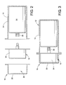
FIGURE 2 is an exploded view of the motor assembly ofFigure 1 ; -
FIGURE 3 is a partially cross-sectional view of the motor assembly ofFigure 1 ; -
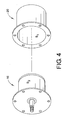
FIGURE 4 is a perspective view of an end cap and encoder with treated surfaces in accordance with the present disclosure; and -
FIGURE 5 is a graph representing torque vs speed for a test motor with various configurations represented. - Motors used in certain applications, such as food processing (e.g., food grade motors), typically have an aluminum housing that is typically painted white on the outside per government regulations. In contrast, motors used outside of such applications are generally black. It has been found that, for a given motor, painting the outside of its housing white results in less radiation heat transfer from the housing exterior surface to ambient. This increases interior motor component temperatures and results in a significant decrease in motor performance.
- In accordance with the present disclosure, interior surfaces of a motor are treated to increase radiational heat transfer from interior motor components to the exterior of the motor. In one exemplary embodiment, the interior surfaces of a motor housing and the encoder itself are painted and/or anodized black to increase the emissivity of the components and thereby increase radiational heat transfer from the encoder to the exterior of the motor.
- With reference to
FIGURES 1-3 , an exemplary electric motor assembly in accordance with the present disclosure is illustrated and identified generally byreference numeral 10. The electric motor assembly generally comprises ahousing 12 in which the internal motor components, including arotor 14 and anencoder 16, are supported. The housing is comprised of two main components, amotor housing portion 18 and an encoder housing portion, referred to herein as an end cap or arear cover 20. Themotor housing portion 18 includes a motor compartment orcavity 24 in which the rotor 14 (and stator) is supported, and therear cover 20 defines an encoder compartment orcavity 26 in which theencoder 16 is contained. The interior of themotor housing 12 andencoder compartment 26 are exemplary in nature, and other configurations are possible. For example, a single housing component can include both the motor housing and the encoder compartment. - As best seen in
FIGURE 3 , theencoder 16 generally includes acylindrical body 30 that houses electrical components. Theencoder 16 is mounted axially coextensive with a portion of ashaft 30 of themotor rotor 14, and can be configured to sense both shaft RPM and angular position, as conventional. It will be appreciated that theencoder 16 is shown in schematic form in the drawings, and that the specific details of theencoder 16 is not germane to the present discussion. - In a typical motor assembly, both the
encoder body 34 and therear cover 20 that surrounds theencoder 16 are metal. In many applications, theencoder body 34 andend cap 20 are aluminum. Therear cover 20 can also be steel or stainless steel along with the motor housing. Bare aluminum, however, has poor radiation properties that limit the amount of radiational heat transfer from the interior of the motor to the ambient environment outside the motor housing. - With reference to
FIGURE 4 , and in accordance with the present disclosure, the interior surfaces of themotor 10 including the interior surface S1 of theend cap 20 and the outer surface S2 of theencoder body 34 are treated to increase emissivity and thereby increase the rate of heat transferred by radiation from the encoder to the ambient environment outside the housing. It will be appreciated that the term treated is intended to include, but is not limited to, painting, coating, plating, dyeing, tinting, or otherwise changing the surfaces to increase emissivity over a base emissivity of the bare, untreated material. For example, in one embodiment, theencoder body 34 is anodized black and the interior surface of therear cover 20 is painted black. In another embodiment, both components can be anodized or painted, or both. In still another embodiment, the end cap is anodized black, or just the encoder exterior is black)As compared to bare aluminum with an emissivity of approximately 0.09, aluminum treated with a black coloring has an emissivity of approximately 0.9 to 0.95. - In the illustrated embodiment, the encoder and end cap are each cylindrical. Radiation exchange between cylindrical bodies is represented by the equation:

- Where σ = Stefan-Boltzmann = constant, and for a given geometry, A1 and A2 are constant.
- For a given Temperature Delta (between Encoder and Cover), the Radiation Heat Transfer, q, simplifies to a function of Emissivities:

- It will now be appreciated that, as encoder emissivity goes up, its reciprocal goes down, and heat transfer goes up; as rear cover emissivity goes up, its reciprocal goes down, and heat transfer goes up.
- Testing has shown a substantial improvement in performance of the motor through such treatment of the internal components.
- In testing, one motor experienced an increase in internal temperature of 5.47 degrees C as a result of the outside of the motor housing being painted white. As illustrated in the graph shown in
FIGURE 5 , the performance of the original motor with black outer is represented by the uppermost line. After painting the outside of the housing white, the performance of the motor was degraded as shown by the lowermost line. In between the uppermost line and the lowermost lines are two lines representing improved performance based on treatment of the interior surface of the motor. In one test, the rear cover and the encoder were both anodized black. In another test, the rear cover was painted black, while the encoder was anodized black. Both configurations resulted in improved motor performance as illustrated in the graph. Additional testing was performed on other motor models with similar results. - It will be appreciated that increasing the emissivity of the encoder and or housing results in better heat dissipation. Accordingly, aspects of the present disclosure can be applied to housings having exterior colors other than white.
- The exemplary embodiment has been described with reference to the preferred embodiments. Obviously, modifications and alterations will occur to others upon reading and understanding the preceding detailed description. It is intended that the exemplary embodiment be construed as including all such modifications and alterations insofar as they come within the scope of the appended claims or the equivalents thereof. The following is a list of further preferred embodiments of the invention:
- Embodiment 1. A motor assembly comprising:
- a housing including a motor portion having an opening for receiving a motor;
- a motor received in the housing; an encoder coupled to the motor;
- an end cap for enclosing the opening of the motor portion of the housing, the end cap at least partially surrounding the encoder;
- Embodiment 2. The motor assembly of embodiment 1, wherein the end cap is aluminum, and the interior surface of the end cap is anodized black.
- Embodiment 3. The motor assembly of embodiment 1, wherein the interior surface of the end cap is painted black.
- Embodiment 4. The motor assembly of embodiment 1, wherein both the encoder and the interior surface of the end cap are anodized black.
- Embodiment 5. The motor assembly of embodiment 1, wherein both the encoder and the interior surface of the end cap are painted black.
- Embodiment 6. The motor assembly of embodiment 1, wherein the encoder is painted black.
- Embodiment 7. The motor assembly of embodiment 1, wherein the motor assembly is a food-grade motor assembly having an exterior of the housing painted white.
- Embodiment 8. An end cap for a motor assembly comprising;
- a body having an interior surface and an exterior surface; wherein the exterior surface is painted white; and wherein the interior surface has an emissivity greater than 0.9.
- Embodiment 9. The end cap of embodiment 8, wherein the interior surface is painted black.
-
Embodiment 10. The end cap of embodiment 8, wherein the body is aluminum, and wherein the interior surface is anodized black. - Embodiment 11. The end cap of embodiment 8, wherein the body is aluminum, wherein the interior and exterior surfaces of the body are anodized black, and wherein the exterior anodized black surface is painted white.
-
Embodiment 12. A method of increasing heat transfer in a motor assembly comprising:- providing a motor component;
- providing a motor housing for receiving the motor component; and
- increasing the emissivity of at least one of the motor component or an interior surface of the motor housing;
- Embodiment 13. The method of
embodiment 12, wherein the increasing the emissivity includes painting with black paint. -
Embodiment 14. The method ofembodiment 12, wherein the increasing the emissivity includes black anodizing.
Claims (11)
- A motor assembly (10) comprising:a housing (12) including a motor portion having an opening for receiving a motor;a motor (14) received in the housing (12);an encoder (16) coupled to the motor (14);an end cap (20) for enclosing the opening of the motor portion of the housing (12), the end cap (20) at least partially surrounding the encoder (16);wherein at least one of an interior surface of the end cap (20) or an exterior surface of the encoder (16) comprise a material having an emissivity greater than 0.9.
- The motor assembly (10) of claim 1, wherein the end cap (20) is aluminum, and the interior surface of the end cap (20) is anodized black.
- The motor assembly (10) of any one of claims 1-2, wherein the interior surface of the end cap (20) is painted black.
- The motor assembly (10) of any one of claims 1-3, wherein both the encoder (16) and the interior surface of the end cap (20) are anodized black.
- The motor assembly (10) of any one of claims 1-4, wherein both the encoder (16) and the interior surface of the end cap (20) are painted black.
- The motor assembly (10) of any one of claims 1-5, wherein the encoder (16) is painted black.
- The motor assembly (10) of any one of claims 1-6, wherein the motor assembly (10) is a food-grade motor assembly, and an exterior of the housing (12) is white.
- A method of increasing heat transfer in a motor assembly comprising:providing a motor component;providing a motor housing for receiving the motor component; andincreasing the emissivity of at least one of the motor component or an interior surface of the motor housing;wherein the emissivity is increased to at least 0.9.
- The method of claim 8, wherein the increasing the emissivity includes painting with black paint.
- The method of any one of claims 8-9, wherein the increasing the emissivity includes black anodizing.
- The method of any one of claims 8-10, wherein the motor assembly includes a food-grade motor assembly, and the motor housing includes a white exterior.
Applications Claiming Priority (1)
| Application Number | Priority Date | Filing Date | Title |
|---|---|---|---|
| US14/231,948 US9762107B2 (en) | 2014-04-01 | 2014-04-01 | Radiation heat transfer of internal motor components by electro-magnetic waves |
Publications (3)
| Publication Number | Publication Date |
|---|---|
| EP2928049A2 true EP2928049A2 (en) | 2015-10-07 |
| EP2928049A3 EP2928049A3 (en) | 2016-06-08 |
| EP2928049B1 EP2928049B1 (en) | 2019-10-16 |
Family
ID=52807668
Family Applications (1)
| Application Number | Title | Priority Date | Filing Date |
|---|---|---|---|
| EP15161861.8A Active EP2928049B1 (en) | 2014-04-01 | 2015-03-31 | Radiation heat transfer of motor components |
Country Status (3)
| Country | Link |
|---|---|
| US (2) | US9762107B2 (en) |
| EP (1) | EP2928049B1 (en) |
| CN (1) | CN104979934B (en) |
Cited By (1)
| Publication number | Priority date | Publication date | Assignee | Title |
|---|---|---|---|---|
| EP3528371A1 (en) * | 2018-02-19 | 2019-08-21 | ABB Schweiz AG | Housing for an electrical machine, an electrical machine including the housing, and a method for increasing the cooling of the electrical machine |
Families Citing this family (5)
| Publication number | Priority date | Publication date | Assignee | Title |
|---|---|---|---|---|
| CN110247517B (en) * | 2018-03-09 | 2021-10-26 | 西门子公司 | Encoder and motor assembly |
| CN108377069A (en) * | 2018-03-12 | 2018-08-07 | 珠海格力节能环保制冷技术研究中心有限公司 | Motor |
| US20220136738A1 (en) * | 2019-02-25 | 2022-05-05 | Khalifa University of Science and Technology | Top-Surface-Cooled, Directly Irradiated Liquid Receiver For Concentrated Solar Power |
| DE102020100271A1 (en) * | 2020-01-09 | 2021-07-15 | Bayerische Motoren Werke Aktiengesellschaft | Rotor position sensor and motor assembly |
| DE102021109789A1 (en) | 2021-04-19 | 2022-10-20 | Nidec Gpm Gmbh | Method for producing a thin-walled ceramic component, in particular a can or containment shell, thin-walled ceramic component and electric motor having the thin-walled ceramic component and glandless pump |
Family Cites Families (10)
| Publication number | Priority date | Publication date | Assignee | Title |
|---|---|---|---|---|
| US4293785A (en) * | 1978-09-05 | 1981-10-06 | Jackson Research, Inc. | Rotating electric machines with enhanced radiation cooling |
| GB2184610A (en) | 1985-12-02 | 1987-06-24 | Johnson Electric Ind Mfg | An end cap for an electric motor |
| US5483229A (en) | 1993-02-18 | 1996-01-09 | Yokogawa Electric Corporation | Input-output unit |
| US6078117A (en) * | 1997-08-27 | 2000-06-20 | Nartron Corporation | End cap assembly and electrical motor utilizing same |
| US5831358A (en) * | 1997-09-30 | 1998-11-03 | General Electric Company | Rotor end cap |
| US5932942A (en) * | 1997-12-16 | 1999-08-03 | Reliance Electric Industrial Company | DC motor drive with improved thermal characteristics |
| US5939807A (en) * | 1997-12-16 | 1999-08-17 | Reliance Electric Industrial Company | Cap mounted drive for a brushless DC motor |
| US6300693B1 (en) * | 1999-03-05 | 2001-10-09 | Emerson Electric Co. | Electric motor cooling jacket assembly and method of manufacture |
| US8006164B2 (en) * | 2006-09-29 | 2011-08-23 | Intel Corporation | Memory cell supply voltage control based on error detection |
| US9543811B2 (en) * | 2012-09-14 | 2017-01-10 | Rockwell Automation Technologies, Inc. | Heatsink design with thermal insulator to reduce encoder temperature |
-
2014
- 2014-04-01 US US14/231,948 patent/US9762107B2/en active Active
-
2015
- 2015-03-31 EP EP15161861.8A patent/EP2928049B1/en active Active
- 2015-04-01 CN CN201510151767.9A patent/CN104979934B/en active Active
-
2017
- 2017-08-10 US US15/673,785 patent/US10566878B2/en active Active
Non-Patent Citations (1)
| Title |
|---|
| None |
Cited By (2)
| Publication number | Priority date | Publication date | Assignee | Title |
|---|---|---|---|---|
| EP3528371A1 (en) * | 2018-02-19 | 2019-08-21 | ABB Schweiz AG | Housing for an electrical machine, an electrical machine including the housing, and a method for increasing the cooling of the electrical machine |
| WO2019158241A1 (en) | 2018-02-19 | 2019-08-22 | Abb Schweiz Ag | Housing for an electrical machine, an electrical machine including the housing, and a method for increasing the cooling of the electrical machine |
Also Published As
| Publication number | Publication date |
|---|---|
| EP2928049B1 (en) | 2019-10-16 |
| US10566878B2 (en) | 2020-02-18 |
| US20150280527A1 (en) | 2015-10-01 |
| CN104979934B (en) | 2018-04-03 |
| US9762107B2 (en) | 2017-09-12 |
| EP2928049A3 (en) | 2016-06-08 |
| CN104979934A (en) | 2015-10-14 |
| US20170366072A1 (en) | 2017-12-21 |
Similar Documents
| Publication | Publication Date | Title |
|---|---|---|
| US10566878B2 (en) | Radiation heat transfer of internal motor components by electro-magnetic waves | |
| EP3659841A8 (en) | Axle assembly having an electric motor module and method of assembly | |
| US11750062B2 (en) | Drive device with circulating airflow | |
| US20160211727A1 (en) | Motor assembly | |
| US11970220B2 (en) | Electric power steering apparatus | |
| US9068481B2 (en) | Electronic component accommodation member and valve timing control device equipped with the same | |
| US20150326089A1 (en) | Actuator | |
| MX2019004467A (en) | Capping head for the application of caps on containers or bottles. | |
| US20200198667A1 (en) | Covering system for wheelset shafts of rail vehicles | |
| GB2513425A (en) | Linear transmission cylinder and driving motor thereof | |
| KR860009520A (en) | Alternator | |
| JP4941428B2 (en) | Rotating electric machine for vehicles | |
| KR101437377B1 (en) | Vehicle rotating electrical machine and cap structure of pulley for the same | |
| Yigit et al. | Influences of aspect ratio on natural convection of power-law fluids in cylindrical annular space with differentially heated vertical walls | |
| US9590464B2 (en) | Electric motor having air tightness test holes | |
| FR3020416B1 (en) | FAN FOR MOTOR VEHICLE ROTATING ELECTRIC MACHINE | |
| US9543811B2 (en) | Heatsink design with thermal insulator to reduce encoder temperature | |
| US9812924B2 (en) | Motor assembly for an electric power steering assembly | |
| CN112204856A (en) | Electric actuator | |
| US9229021B2 (en) | Measuring device with a multi-walled housing | |
| US20210001918A1 (en) | Electric power steering apparatus | |
| EP2383871A2 (en) | Electric motor with a control device enclosed in a motor housing | |
| US11489406B2 (en) | Drive device with circulating airflow | |
| US20140062235A1 (en) | Rotating electrical machine | |
| CN106981951B (en) | Electric motor |
Legal Events
| Date | Code | Title | Description |
|---|---|---|---|
| PUAI | Public reference made under article 153(3) epc to a published international application that has entered the european phase |
Free format text: ORIGINAL CODE: 0009012 |
|
| AK | Designated contracting states |
Kind code of ref document: A2 Designated state(s): AL AT BE BG CH CY CZ DE DK EE ES FI FR GB GR HR HU IE IS IT LI LT LU LV MC MK MT NL NO PL PT RO RS SE SI SK SM TR |
|
| AX | Request for extension of the european patent |
Extension state: BA ME |
|
| PUAL | Search report despatched |
Free format text: ORIGINAL CODE: 0009013 |
|
| AK | Designated contracting states |
Kind code of ref document: A3 Designated state(s): AL AT BE BG CH CY CZ DE DK EE ES FI FR GB GR HR HU IE IS IT LI LT LU LV MC MK MT NL NO PL PT RO RS SE SI SK SM TR |
|
| AX | Request for extension of the european patent |
Extension state: BA ME |
|
| RIC1 | Information provided on ipc code assigned before grant |
Ipc: H02K 5/06 20060101ALI20160503BHEP Ipc: H02K 9/22 20060101AFI20160503BHEP |
|
| 17P | Request for examination filed |
Effective date: 20161020 |
|
| RBV | Designated contracting states (corrected) |
Designated state(s): AL AT BE BG CH CY CZ DE DK EE ES FI FR GB GR HR HU IE IS IT LI LT LU LV MC MK MT NL NO PL PT RO RS SE SI SK SM TR |
|
| STAA | Information on the status of an ep patent application or granted ep patent |
Free format text: STATUS: EXAMINATION IS IN PROGRESS |
|
| 17Q | First examination report despatched |
Effective date: 20180913 |
|
| RIC1 | Information provided on ipc code assigned before grant |
Ipc: H02K 11/21 20160101ALI20190131BHEP Ipc: H02K 5/02 20060101AFI20190131BHEP Ipc: H02K 9/22 20060101ALI20190131BHEP |
|
| GRAP | Despatch of communication of intention to grant a patent |
Free format text: ORIGINAL CODE: EPIDOSNIGR1 |
|
| STAA | Information on the status of an ep patent application or granted ep patent |
Free format text: STATUS: GRANT OF PATENT IS INTENDED |
|
| INTG | Intention to grant announced |
Effective date: 20190322 |
|
| REG | Reference to a national code |
Ref country code: DE Ref legal event code: R079 Ref document number: 602015039780 Country of ref document: DE Free format text: PREVIOUS MAIN CLASS: H02K0009220000 Ipc: C25D0011140000 |
|
| GRAJ | Information related to disapproval of communication of intention to grant by the applicant or resumption of examination proceedings by the epo deleted |
Free format text: ORIGINAL CODE: EPIDOSDIGR1 |
|
| GRAP | Despatch of communication of intention to grant a patent |
Free format text: ORIGINAL CODE: EPIDOSNIGR1 |
|
| RIC1 | Information provided on ipc code assigned before grant |
Ipc: H02K 9/22 20060101ALI20190516BHEP Ipc: C25D 11/14 20060101AFI20190516BHEP Ipc: H02K 11/21 20160101ALI20190516BHEP Ipc: H02K 5/02 20060101ALI20190516BHEP |
|
| INTG | Intention to grant announced |
Effective date: 20190613 |
|
| GRAS | Grant fee paid |
Free format text: ORIGINAL CODE: EPIDOSNIGR3 |
|
| GRAA | (expected) grant |
Free format text: ORIGINAL CODE: 0009210 |
|
| STAA | Information on the status of an ep patent application or granted ep patent |
Free format text: STATUS: THE PATENT HAS BEEN GRANTED |
|
| AK | Designated contracting states |
Kind code of ref document: B1 Designated state(s): AL AT BE BG CH CY CZ DE DK EE ES FI FR GB GR HR HU IE IS IT LI LT LU LV MC MK MT NL NO PL PT RO RS SE SI SK SM TR |
|
| REG | Reference to a national code |
Ref country code: GB Ref legal event code: FG4D |
|
| REG | Reference to a national code |
Ref country code: CH Ref legal event code: EP |
|
| REG | Reference to a national code |
Ref country code: DE Ref legal event code: R096 Ref document number: 602015039780 Country of ref document: DE |
|
| REG | Reference to a national code |
Ref country code: IE Ref legal event code: FG4D |
|
| REG | Reference to a national code |
Ref country code: AT Ref legal event code: REF Ref document number: 1191335 Country of ref document: AT Kind code of ref document: T Effective date: 20191115 |
|
| REG | Reference to a national code |
Ref country code: NL Ref legal event code: MP Effective date: 20191016 |
|
| REG | Reference to a national code |
Ref country code: LT Ref legal event code: MG4D |
|
| REG | Reference to a national code |
Ref country code: AT Ref legal event code: MK05 Ref document number: 1191335 Country of ref document: AT Kind code of ref document: T Effective date: 20191016 |
|
| PG25 | Lapsed in a contracting state [announced via postgrant information from national office to epo] |
Ref country code: NL Free format text: LAPSE BECAUSE OF FAILURE TO SUBMIT A TRANSLATION OF THE DESCRIPTION OR TO PAY THE FEE WITHIN THE PRESCRIBED TIME-LIMIT Effective date: 20191016 Ref country code: ES Free format text: LAPSE BECAUSE OF FAILURE TO SUBMIT A TRANSLATION OF THE DESCRIPTION OR TO PAY THE FEE WITHIN THE PRESCRIBED TIME-LIMIT Effective date: 20191016 Ref country code: LT Free format text: LAPSE BECAUSE OF FAILURE TO SUBMIT A TRANSLATION OF THE DESCRIPTION OR TO PAY THE FEE WITHIN THE PRESCRIBED TIME-LIMIT Effective date: 20191016 Ref country code: PL Free format text: LAPSE BECAUSE OF FAILURE TO SUBMIT A TRANSLATION OF THE DESCRIPTION OR TO PAY THE FEE WITHIN THE PRESCRIBED TIME-LIMIT Effective date: 20191016 Ref country code: GR Free format text: LAPSE BECAUSE OF FAILURE TO SUBMIT A TRANSLATION OF THE DESCRIPTION OR TO PAY THE FEE WITHIN THE PRESCRIBED TIME-LIMIT Effective date: 20200117 Ref country code: AT Free format text: LAPSE BECAUSE OF FAILURE TO SUBMIT A TRANSLATION OF THE DESCRIPTION OR TO PAY THE FEE WITHIN THE PRESCRIBED TIME-LIMIT Effective date: 20191016 Ref country code: NO Free format text: LAPSE BECAUSE OF FAILURE TO SUBMIT A TRANSLATION OF THE DESCRIPTION OR TO PAY THE FEE WITHIN THE PRESCRIBED TIME-LIMIT Effective date: 20200116 Ref country code: PT Free format text: LAPSE BECAUSE OF FAILURE TO SUBMIT A TRANSLATION OF THE DESCRIPTION OR TO PAY THE FEE WITHIN THE PRESCRIBED TIME-LIMIT Effective date: 20200217 Ref country code: LV Free format text: LAPSE BECAUSE OF FAILURE TO SUBMIT A TRANSLATION OF THE DESCRIPTION OR TO PAY THE FEE WITHIN THE PRESCRIBED TIME-LIMIT Effective date: 20191016 Ref country code: SE Free format text: LAPSE BECAUSE OF FAILURE TO SUBMIT A TRANSLATION OF THE DESCRIPTION OR TO PAY THE FEE WITHIN THE PRESCRIBED TIME-LIMIT Effective date: 20191016 Ref country code: FI Free format text: LAPSE BECAUSE OF FAILURE TO SUBMIT A TRANSLATION OF THE DESCRIPTION OR TO PAY THE FEE WITHIN THE PRESCRIBED TIME-LIMIT Effective date: 20191016 Ref country code: BG Free format text: LAPSE BECAUSE OF FAILURE TO SUBMIT A TRANSLATION OF THE DESCRIPTION OR TO PAY THE FEE WITHIN THE PRESCRIBED TIME-LIMIT Effective date: 20200116 |
|
| PG25 | Lapsed in a contracting state [announced via postgrant information from national office to epo] |
Ref country code: RS Free format text: LAPSE BECAUSE OF FAILURE TO SUBMIT A TRANSLATION OF THE DESCRIPTION OR TO PAY THE FEE WITHIN THE PRESCRIBED TIME-LIMIT Effective date: 20191016 Ref country code: IS Free format text: LAPSE BECAUSE OF FAILURE TO SUBMIT A TRANSLATION OF THE DESCRIPTION OR TO PAY THE FEE WITHIN THE PRESCRIBED TIME-LIMIT Effective date: 20200224 Ref country code: HR Free format text: LAPSE BECAUSE OF FAILURE TO SUBMIT A TRANSLATION OF THE DESCRIPTION OR TO PAY THE FEE WITHIN THE PRESCRIBED TIME-LIMIT Effective date: 20191016 |
|
| PG25 | Lapsed in a contracting state [announced via postgrant information from national office to epo] |
Ref country code: AL Free format text: LAPSE BECAUSE OF FAILURE TO SUBMIT A TRANSLATION OF THE DESCRIPTION OR TO PAY THE FEE WITHIN THE PRESCRIBED TIME-LIMIT Effective date: 20191016 |
|
| REG | Reference to a national code |
Ref country code: DE Ref legal event code: R097 Ref document number: 602015039780 Country of ref document: DE |
|
| PG2D | Information on lapse in contracting state deleted |
Ref country code: IS |
|
| PG25 | Lapsed in a contracting state [announced via postgrant information from national office to epo] |
Ref country code: EE Free format text: LAPSE BECAUSE OF FAILURE TO SUBMIT A TRANSLATION OF THE DESCRIPTION OR TO PAY THE FEE WITHIN THE PRESCRIBED TIME-LIMIT Effective date: 20191016 Ref country code: DK Free format text: LAPSE BECAUSE OF FAILURE TO SUBMIT A TRANSLATION OF THE DESCRIPTION OR TO PAY THE FEE WITHIN THE PRESCRIBED TIME-LIMIT Effective date: 20191016 Ref country code: RO Free format text: LAPSE BECAUSE OF FAILURE TO SUBMIT A TRANSLATION OF THE DESCRIPTION OR TO PAY THE FEE WITHIN THE PRESCRIBED TIME-LIMIT Effective date: 20191016 Ref country code: CZ Free format text: LAPSE BECAUSE OF FAILURE TO SUBMIT A TRANSLATION OF THE DESCRIPTION OR TO PAY THE FEE WITHIN THE PRESCRIBED TIME-LIMIT Effective date: 20191016 Ref country code: IS Free format text: LAPSE BECAUSE OF FAILURE TO SUBMIT A TRANSLATION OF THE DESCRIPTION OR TO PAY THE FEE WITHIN THE PRESCRIBED TIME-LIMIT Effective date: 20200216 |
|
| PLBE | No opposition filed within time limit |
Free format text: ORIGINAL CODE: 0009261 |
|
| STAA | Information on the status of an ep patent application or granted ep patent |
Free format text: STATUS: NO OPPOSITION FILED WITHIN TIME LIMIT |
|
| PG25 | Lapsed in a contracting state [announced via postgrant information from national office to epo] |
Ref country code: SM Free format text: LAPSE BECAUSE OF FAILURE TO SUBMIT A TRANSLATION OF THE DESCRIPTION OR TO PAY THE FEE WITHIN THE PRESCRIBED TIME-LIMIT Effective date: 20191016 Ref country code: SK Free format text: LAPSE BECAUSE OF FAILURE TO SUBMIT A TRANSLATION OF THE DESCRIPTION OR TO PAY THE FEE WITHIN THE PRESCRIBED TIME-LIMIT Effective date: 20191016 Ref country code: IT Free format text: LAPSE BECAUSE OF FAILURE TO SUBMIT A TRANSLATION OF THE DESCRIPTION OR TO PAY THE FEE WITHIN THE PRESCRIBED TIME-LIMIT Effective date: 20191016 |
|
| 26N | No opposition filed |
Effective date: 20200717 |
|
| PG25 | Lapsed in a contracting state [announced via postgrant information from national office to epo] |
Ref country code: MC Free format text: LAPSE BECAUSE OF FAILURE TO SUBMIT A TRANSLATION OF THE DESCRIPTION OR TO PAY THE FEE WITHIN THE PRESCRIBED TIME-LIMIT Effective date: 20191016 |
|
| REG | Reference to a national code |
Ref country code: CH Ref legal event code: PL |
|
| PG25 | Lapsed in a contracting state [announced via postgrant information from national office to epo] |
Ref country code: SI Free format text: LAPSE BECAUSE OF FAILURE TO SUBMIT A TRANSLATION OF THE DESCRIPTION OR TO PAY THE FEE WITHIN THE PRESCRIBED TIME-LIMIT Effective date: 20191016 |
|
| REG | Reference to a national code |
Ref country code: BE Ref legal event code: MM Effective date: 20200331 |
|
| PG25 | Lapsed in a contracting state [announced via postgrant information from national office to epo] |
Ref country code: LU Free format text: LAPSE BECAUSE OF NON-PAYMENT OF DUE FEES Effective date: 20200331 |
|
| PG25 | Lapsed in a contracting state [announced via postgrant information from national office to epo] |
Ref country code: CH Free format text: LAPSE BECAUSE OF NON-PAYMENT OF DUE FEES Effective date: 20200331 Ref country code: LI Free format text: LAPSE BECAUSE OF NON-PAYMENT OF DUE FEES Effective date: 20200331 Ref country code: IE Free format text: LAPSE BECAUSE OF NON-PAYMENT OF DUE FEES Effective date: 20200331 |
|
| PG25 | Lapsed in a contracting state [announced via postgrant information from national office to epo] |
Ref country code: BE Free format text: LAPSE BECAUSE OF NON-PAYMENT OF DUE FEES Effective date: 20200331 |
|
| PG25 | Lapsed in a contracting state [announced via postgrant information from national office to epo] |
Ref country code: TR Free format text: LAPSE BECAUSE OF FAILURE TO SUBMIT A TRANSLATION OF THE DESCRIPTION OR TO PAY THE FEE WITHIN THE PRESCRIBED TIME-LIMIT Effective date: 20191016 Ref country code: MT Free format text: LAPSE BECAUSE OF FAILURE TO SUBMIT A TRANSLATION OF THE DESCRIPTION OR TO PAY THE FEE WITHIN THE PRESCRIBED TIME-LIMIT Effective date: 20191016 Ref country code: CY Free format text: LAPSE BECAUSE OF FAILURE TO SUBMIT A TRANSLATION OF THE DESCRIPTION OR TO PAY THE FEE WITHIN THE PRESCRIBED TIME-LIMIT Effective date: 20191016 |
|
| PG25 | Lapsed in a contracting state [announced via postgrant information from national office to epo] |
Ref country code: MK Free format text: LAPSE BECAUSE OF FAILURE TO SUBMIT A TRANSLATION OF THE DESCRIPTION OR TO PAY THE FEE WITHIN THE PRESCRIBED TIME-LIMIT Effective date: 20191016 |
|
| P01 | Opt-out of the competence of the unified patent court (upc) registered |
Effective date: 20230404 |
|
| PGFP | Annual fee paid to national office [announced via postgrant information from national office to epo] |
Ref country code: GB Payment date: 20260219 Year of fee payment: 12 |
|
| PGFP | Annual fee paid to national office [announced via postgrant information from national office to epo] |
Ref country code: DE Payment date: 20260219 Year of fee payment: 12 |
|
| PGFP | Annual fee paid to national office [announced via postgrant information from national office to epo] |
Ref country code: FR Payment date: 20260219 Year of fee payment: 12 |