EP2927909A1 - Device for quantum beam generation, method for quantum beam generation, and device for laser fusion - Google Patents
Device for quantum beam generation, method for quantum beam generation, and device for laser fusion Download PDFInfo
- Publication number
- EP2927909A1 EP2927909A1 EP13857800.0A EP13857800A EP2927909A1 EP 2927909 A1 EP2927909 A1 EP 2927909A1 EP 13857800 A EP13857800 A EP 13857800A EP 2927909 A1 EP2927909 A1 EP 2927909A1
- Authority
- EP
- European Patent Office
- Prior art keywords
- target
- laser light
- controller
- emission
- monitoring area
- Prior art date
- Legal status (The legal status is an assumption and is not a legal conclusion. Google has not performed a legal analysis and makes no representation as to the accuracy of the status listed.)
- Granted
Links
Images

Classifications
-
- G—PHYSICS
- G21—NUCLEAR PHYSICS; NUCLEAR ENGINEERING
- G21B—FUSION REACTORS
- G21B1/00—Thermonuclear fusion reactors
- G21B1/11—Details
- G21B1/23—Optical systems, e.g. for irradiating targets, for heating plasma or for plasma diagnostics
-
- G—PHYSICS
- G03—PHOTOGRAPHY; CINEMATOGRAPHY; ANALOGOUS TECHNIQUES USING WAVES OTHER THAN OPTICAL WAVES; ELECTROGRAPHY; HOLOGRAPHY
- G03F—PHOTOMECHANICAL PRODUCTION OF TEXTURED OR PATTERNED SURFACES, e.g. FOR PRINTING, FOR PROCESSING OF SEMICONDUCTOR DEVICES; MATERIALS THEREFOR; ORIGINALS THEREFOR; APPARATUS SPECIALLY ADAPTED THEREFOR
- G03F7/00—Photomechanical, e.g. photolithographic, production of textured or patterned surfaces, e.g. printing surfaces; Materials therefor, e.g. comprising photoresists; Apparatus specially adapted therefor
- G03F7/70—Microphotolithographic exposure; Apparatus therefor
- G03F7/70008—Production of exposure light, i.e. light sources
- G03F7/70033—Production of exposure light, i.e. light sources by plasma extreme ultraviolet [EUV] sources
-
- G—PHYSICS
- G21—NUCLEAR PHYSICS; NUCLEAR ENGINEERING
- G21B—FUSION REACTORS
- G21B1/00—Thermonuclear fusion reactors
- G21B1/03—Thermonuclear fusion reactors with inertial plasma confinement
-
- G—PHYSICS
- G21—NUCLEAR PHYSICS; NUCLEAR ENGINEERING
- G21K—HANDLING OF PARTICLES OR IONISING RADIATION NOT OTHERWISE PROVIDED FOR; IRRADIATION DEVICES; GAMMA RAY OR X-RAY MICROSCOPES
- G21K5/00—Irradiation devices
- G21K5/04—Irradiation devices with beam-forming means
-
- G—PHYSICS
- G21—NUCLEAR PHYSICS; NUCLEAR ENGINEERING
- G21K—HANDLING OF PARTICLES OR IONISING RADIATION NOT OTHERWISE PROVIDED FOR; IRRADIATION DEVICES; GAMMA RAY OR X-RAY MICROSCOPES
- G21K5/00—Irradiation devices
- G21K5/10—Irradiation devices with provision for relative movement of beam source and object to be irradiated
-
- Y—GENERAL TAGGING OF NEW TECHNOLOGICAL DEVELOPMENTS; GENERAL TAGGING OF CROSS-SECTIONAL TECHNOLOGIES SPANNING OVER SEVERAL SECTIONS OF THE IPC; TECHNICAL SUBJECTS COVERED BY FORMER USPC CROSS-REFERENCE ART COLLECTIONS [XRACs] AND DIGESTS
- Y02—TECHNOLOGIES OR APPLICATIONS FOR MITIGATION OR ADAPTATION AGAINST CLIMATE CHANGE
- Y02E—REDUCTION OF GREENHOUSE GAS [GHG] EMISSIONS, RELATED TO ENERGY GENERATION, TRANSMISSION OR DISTRIBUTION
- Y02E30/00—Energy generation of nuclear origin
- Y02E30/10—Nuclear fusion reactors
Definitions
- the present invention relates to a device for quantum beam generation, a method for quantum beam generation, and a device for laser fusion.
- Patent Literature 1 discloses a system for extracting energy from a controlled fusion reaction.
- This system includes a target chamber for receiving a fusion target material.
- a plurality of energy drivers are arranged around the target chamber so as to supply energy to the target material in the target chamber to initiate the controlled fusion reaction, releasing energy in the forms of fusion plasma and heat.
- the system is provided with a plurality of structures for extracting energy from the fusion reaction. These structures have devices to extract high-voltage electric current power from the fusion plasma; and means to extract thermal energy from the target chamber.
- Power to the energy drivers can be supplied from the high-voltage DC power extracted from the fusion reaction.
- the energy drivers use an apodizing filter to impart a desired shape to the wavefront of the driving energy for causing the fusion reaction, in order to avoid hydrodynamic instability.
- Patent Literature 2 discloses a laser plasma EUV light source for irradiating a target with laser light to plasmanize the target and extracting EUV light generated on that occasion, as output.
- This laser plasma EUV light source uses a platelike target in a size approximately equal to a focused diameter of the laser light, as the target.
- the target is ejected with a direction of a disc aligned, from a nozzle having a slit-shaped aperture.
- the target is conveyed on a gas stream. He (helium) gas is used in this example. Since the exterior of the nozzle is maintained in a high vacuum, the target ejected from the nozzle reaches an irradiation position with the laser light, while keeping its posture unchanged.
- pulsed laser light from an Nd:YAG laser light source is focused by a lens to be applied onto the target.
- the spot diameter of the laser is the same as the diameter of the target, 1 mm, and the thickness thereof is not more than 1000 nm. Therefore, almost the entire target is plasmanized, while inhibiting generation of debris and enhancing conversion efficiency.
- Non Patent Literature 1 discloses a technology using a long target acceleration mechanism of a linear sabot type and air gun type.
- Non Patent Literature 2 discloses a technology of a target acceleration mechanism of a sabot type.
- the conventional devices for quantum beam generation as described above are not ones that can automatically continuously generate a quantum beam. Therefore, one of objects of the present invention, while having been accomplished in view of the above circumstances, is to provide a device for quantum beam generation, a method for quantum beam generation, and a device for laser fusion enabling automatic, continuous quantum beam generation, for example.
- a device for quantum beam generation is one comprising: a chamber for a target to induce a quantum beam generation reaction; a target supply unit that supplies the target to the chamber; a target monitor that monitors the target present inside the chamber; a laser light irradiator that irradiates the target present inside the chamber, with laser light; and a controller that controls the target supply unit and the laser light irradiator, based on the result of the monitoring by the target monitor, wherein the target supply unit comprises an emission port that emits the target, and emits the target at a timing for emitting, that is controlled by the controller, into a preset emission direction inside the chamber from the emission port, wherein the target monitor comprises a position detector and a time detector, wherein the position detector detects a passing position of the target in a monitoring area and sends position information indicative of the passing position, to the controller, wherein the monitoring area is preliminarily set at a position where the monitoring area intersects with the emission direction inside the chamber, wherein the
- the target supply unit supplies the target to induce the quantum beam generation reaction, at the timing for emitting, that is controlled by the controller, to the inside of the chamber, the target monitor monitors motion of the target inside the chamber, and the controller implements the irradiation of the target with the laser light, based on the result of this monitoring. Therefore, the controller automatically implements the supply of the target and the irradiation of the target with the laser light, whereby continuous quantum beam generation is enabled by the control by the controller.
- the controller controls the target supply unit so as to sequentially emit a plurality of the targets at periodic intervals from the emission port. Therefore, periodic continuous quantum beam generation is enabled by the control by the controller.
- the target supply unit comprises a support table, a disc, a tank, and a driver;
- the support table comprises a principal surface, a back surface, and an emission hole;
- the emission hole has a diameter enough for the target to pass, has the emission port, and penetrates from the principal surface to the back surface;
- the disc comprises a plurality of through holes at preset intervals along an edge of the disc; a center of the disc is held rotatable with respect to the principal surface so that the through holes can overlap with the emission hole; the through holes can enclose the targets on the principal surface;
- the tank comprises a main body and a supply tube and is arranged above the disc;
- the main body can store a plurality of the targets;
- the supply tube has a diameter enough for the target to pass, is connected to the main body, and is arranged above a circumference passing centers of all the through holes;
- the driver comprises a rotary shaft and a motor; the rotary shaft is fixed to the disc at the center of the disc
- the driver comprises a sensor; the sensor detects the number of rotations of the rotary shaft and an axial position of the rotary shaft, and sends to the controller, rotation information indicative of the number of rotations and the axial position; the controller controls rotary motion of the disc, based on the rotation information; and the axial position is a position in a rotating direction of the rotary shaft.
- the rotating state of the disc can be recognized by use of the sensor and thus the controller can rotate the disc in an optionally set period. Therefore, continuous quantum beam generation can be performed in the optionally set period.
- the target supply unit comprises an emission assist; the emission assist is arranged above the emission hole and can press the target present at the emission hole toward the emission direction under control of the controller; the controller calculates a timing for pressing when the through hole of the disc overlaps with the emission hole with rotation of the disc, based on the rotation information, and sends press control information based on the timing for pressing, to the emission assist; and the press control information is information for controlling the emission assist so as to press the target at the timing for pressing.
- the target is forcibly emitted by the emission assist and thus it can avoid an event of failure in emission, despite arrival of the timing for emitting. Furthermore, since the target can be emitted at high speed, the target, when used as cooled at low temperature, can be supplied to the irradiation point within a short time while being maintained at the temperature.
- a method for quantum beam generation is one comprising: an emission step of emitting a target to induce quantum beam generation, to an inside of a chamber; an estimation step of estimating an irradiation point with laser light inside the chamber; a preparation step of preparing irradiation with the laser light; and an output step of outputting the laser light
- the emission step comprises emitting the target at a controllable timing for emitting, into a preset emission direction inside the chamber
- the estimation step comprises detecting a passing position of the target in a monitoring area, measuring an entrance time when the target enters the monitoring area and an exit time when the target exits the monitoring area, calculating the irradiation point using the passing position, and calculating a timing for arriving of the target at the irradiation point, using a width of the monitoring area, the entrance time, the exit time, and a distance from the monitoring area to the irradiation point, wherein the monitoring area is preliminarily set at a position where the monitoring
- the target to induce the quantum beam generation reaction is supplied at the controllable timing for emitting to the inside of the chamber, motion of the target inside the chamber is monitored, and the target is irradiated with the laser light, based on the result of this monitoring. Therefore, the supply of the target and the irradiation of the target with the laser light are automatically carried out, so as to enable continuous quantum beam generation.
- the emission step comprises sequentially emitting a plurality of the targets at periodic intervals. Therefore, it becomes feasible to implement periodic continuous quantum beam generation.
- a device for laser fusion is one comprising: a chamber for a target to induce a fusion reaction; a target supply unit that supplies the target to the chamber; a target monitor that monitors the target present inside the chamber; a laser light irradiator that irradiates the target present inside the chamber, with laser light; and a controller that controls the target supply unit and the laser light irradiator, based on the result of the monitoring by the target monitor, wherein the target supply unit comprises an emission port that emits of the target, and emits the target at a timing for emitting, that is controlled by the controller, into a preset emission direction inside the chamber from the emission port, wherein the target monitor comprises a position detector and a time detector, wherein the position detector detects a passing position of the target in a monitoring area and sends position information indicative of the passing position, to the controller, wherein the monitoring area is preliminarily set at a position where the monitoring area intersects with the emission direction inside the chamber, wherein the
- the target supply unit supplies the target to induce the fusion reaction, at the timing for emitting, that is controlled by the controller, to the inside of the chamber, the target monitor monitors motion of the target inside the chamber, and the controller implements the irradiation of the target with the laser light, based on the result of this monitoring. Therefore, the controller automatically implements the supply of the target and the irradiation of the target with the laser light, whereby continuous fusion reactions are enabled by the control by the controller.
- One aspect of the present invention can provide the device for quantum beam generation and the method for quantum beam generation, that are capable of implementing automatic, continuous quantum beam generation, and the device for laser fusion.
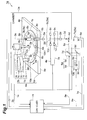
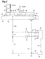
- Figs. 1 and 2 are drawings both schematically showing the configuration of the quantum beam generation device 1a.
- the quantum beam generation device 1a has a chamber 3a, a target supply unit 4a, a target monitor 5a, a laser light irradiator 6a, and a controller 7a.
- the chamber 3a defines a space where a target 2a induces a quantum beam generation reaction.
- the target supply unit 4a supplies the target 2a to the chamber 3a.
- the target monitor 5a monitors the target 2a present inside the chamber 3a.
- the laser light irradiator 6a irradiates the target 2a present inside the chamber 3a, with laser light 8a.
- the controller 7a controls the target supply unit 4a and the laser light irradiator 6a, based on the result of monitoring by the target monitor 5a.
- the target supply unit 4a has an emission port 9b that emits the target 2a.
- the target supply unit 4a supplies the target 2a at a timing for emitting, that is controlled by the controller 7a, into a preset emission direction 3d inside the chamber 3a from the emission port 9b.
- the target supply unit 4a has a support table 9a, a disc 10a, a tank 1b, and a driver 2b.
- the support table 9a has a principal surface 4b, a back surface 5b, and an emission hole 8b.
- the emission hole 8b has the diameter enough for the target 2a to pass.
- the emission hole 8b has the emission port 9b.
- the emission hole 8b penetrates from the principal surface 4b to the back surface 5b.
- the emission port 9b is an aperture on the back surface 5b side.
- the disc 10a has a plurality of through holes 6b at preset intervals (e.g., at equal intervals) along the edge 7b of the disc 10a.
- a center 10b of the disc 10a is held rotatable with respect to the principal surface 4b so that the through holes 6b can overlap with the emission hole 8b.
- the through holes 6b can enclose the respective targets 2a on the principal surface 4b.
- the tank 1b has a main body 1c and a supply tube 2c.
- the tank 1b is arranged above the disc 10a.
- the main body 1c can store a plurality of targets 2a.
- the supply tube 2c has the diameter enough for the target 2a to pass.
- the supply tube 2c is connected to the main body 1c.
- the supply tube 2c is arranged above a circumference 10b1 passing centers of all the through holes 6b.
- the driver 2b has a rotary shaft 4c and a motor 3c.
- the rotary shaft 4c is fixed to the disc 10a at the center 10b of the disc 10a and is rotatable along with the disc 10a.
- the motor 3c is connected to the rotary shaft 4c. The motor 3c rotates the rotary shaft 4c under control of the controller 7a.
- the driver 2b has a sensor 5c.
- the sensor 5c detects the number of rotations of the rotary shaft 4c and the axial position of the rotary shaft 4c.
- the sensor 5c sends to the controller 7a, rotation information 1e indicative of the number of rotations of the rotary shaft 4c and the axial position of the rotary shaft 4c.
- the axial position of the rotary shaft 4c is a position in a rotating direction of the rotary shaft 4c.
- information means electronic data that a CPU of the controller 7a can read.
- the target supply unit 4a has an emission assist 3b.
- the emission assist 3b is arranged above the emission hole 8b.
- the emission assist 3b can press the target 2a present above the emission hole 8b, toward the emission direction 3d under control of the controller 7a.
- the emission assist 3b presses the target 2a, for example, by ejecting gas toward the emission direction 3d.
- the target monitor 5a has a position detector 7c and a time detector 6c.
- the position detector 7c consists of, for example, one or more imaging devices (cameras).
- the position detector 7c detects a passing position of the target 2a in a monitoring area 2d and sends position information 6e indicative of this passing position to the controller 7a.
- the position detector 7c detects the passing position of the target 2a at a timing when the target 2a enters the monitoring area 2d, for example, based on entrance time information 4e.
- the monitoring area 2d is preliminarily set at a position where the monitoring area intersects with the emission direction 3d inside the chamber 3a.
- the passing position detected by the position detector 7c indicates a position in a plane perpendicular to the emission direction 3d (or in a plane parallel to a reference plane 3f shown in Fig. 2 ).
- the time detector 6c measures an entrance time when the target 2a enters the monitoring area 2d, and an exit time when the target 2a exits the monitoring area 2d.
- the time detector 6c sends to the controller 7a, the entrance time information 4e indicative of the entrance time and exit time information 5e indicative of the exit time.
- the time detector 6c is, for example, a photosensor.
- the time detector 6c has a light emitting device 8c, a light emitting device 9c, a light receiving device 10c, and a light receiving device 1d.
- the light receiving device 10c receives light emitted from the light emitting device 8c.
- the light receiving device 1d receives light emitted from the light emitting device 9c.
- the light receiving device 10c converts the received light signal into an electric signal and sends this electric signal as entrance time information 4e to the controller 7a.
- the light receiving device 1d converts the received light signal into an electric signal and sends this electric signal as exit time information 5e to the controller 7a.
- the monitoring area 2d is defined by a travel path of the light emitted from the light emitting device 8c and a travel path of the light emitted from the light emitting device 9c.
- the electric signal (entrance time information 4e) output by the light receiving device 10c takes a value indicative of entrance of the target 2a into the monitoring area 2d.
- the electric signal (exit time information 5e) output by the light receiving device 1d takes a value indicative of exit of the target 2a from the monitoring area 2d.
- the light emitting device 8c and the light emitting device 9c both are, for example, light emitting diodes.
- the light receiving device 10c and the light receiving device 1d both are, for example, photodiodes.
- the time detector 6c may be a plurality of imaging devices or an imaging device that is capable of high-speed photography.
- the laser light irradiator 6a has a laser light output unit 5d and a condensing optical unit 6d.
- the laser light output unit 5d outputs laser light 8a under control of the controller 7a.
- the laser light output unit 5d has a laser light source 9d and a shutter 10d.
- the laser light source 9d emits the laser light at a repetition rate of several ten MHz, irrespective of laser control information 9e.
- the laser light output unit 5d selects laser pulses from a laser pulse train of pulse emissions at the repetition rate of several ten MHz, based on the laser control information 9e, and drives the shutter 10d.
- the laser light output unit 5d opens the shutter 10d with instructions of emission and closes the shutter 10d with instructions of no emission, based on the laser control information 9e.
- the condensing optical unit 6d condenses the laser light 8a output from the laser light output unit 5d, based on control by the controller 7a.
- the condensing optical unit 6d has a plurality of mirrors, e.g., mirror 7d and mirror 8d.
- the condensing optical unit 6d moves arrangements, for example, of the mirror 7d and the mirror 8d, based on condensing control information 8e.
- the controller 7a calculates a timing (timing for pressing) when each through hole 6b of the disc 10a overlaps with the emission hole 8b during rotation of the disc 10a, based on the rotation information 1e.
- the controller 7a sends press control information 3e based on the timing for pressing, to the emission assist 3b.
- the press control information 3e is information for controlling the emission assist 3b so as to press the target at the timing for pressing, that is calculated by the controller 7a.
- the controller 7a controls the target supply unit 4a so as to sequentially emit a plurality of targets 2a at periodic intervals from the emission port 9b.
- the controller 7a controls the rotary motion of the disc 10a, based on the rotation information 1e.
- the controller 7a calculates an irradiation point 4d with the laser light 8a, using the position information 6e.
- the irradiation point 4d is a point included in the reference plane 3f.
- the reference plane 3f is a plane a distance of which is constant from the principal surface 4b of the support table 9a (the distance is the sum of distance 10e, width If, and distance 2f) and which is perpendicular to the emission direction 3d.
- the controller 7a sends the condensing control information 8e based on the irradiation point 4d, to the condensing optical unit 6d.
- the controller 7 a calculates a timing for arriving of the target 2a at the irradiation point 4d, using the width 1f of the monitoring area 2d, the entrance time information 4e, the exit time information 5e, and the distance 2f from the monitoring area 2d to the irradiation point 4d.
- the controller 7 a sends the laser control information 9e based on the timing for arriving, to the laser light output unit 5d.
- the condensing control information 8e is information for controlling the condensing optical unit 6d so as to condense the laser light 8a from the laser light output unit 5d, to the irradiation point 4d.
- the laser control information 9e is information for controlling the laser light output unit 5d so as to output the laser light 8a at the timing for arriving, that is calculated by the controller 7a. All pieces of the information indicative of the distance 10e, the information indicative of the width If, and the information indicative of the distance 2f are preliminarily stored as electronic data in a memory of the controller 7a.
- the diameter of the emission hole 8b is, for example, not less than 101% and not more than 120% of the diameter of the target 2a.
- the diameter of the supply tube 2c is, for example, not less than 101% and not more than 120% of the diameter of the target 2a.
- the controller 7a implements emissions of the targets 2a, for example, in the range of not less than 10 Hz and not more than 100 Hz.
- the emission assist 3b can set the initial velocity of the target 2a upon emission from the emission port 9b, for example, in the range of not less than several m/s and not more than several hundred m/s.
- the emission assist 3b ejects gas toward the emission direction 3d, for example, only in a period of not less than several ms and not more than several hundred ms, so as to press the target 2a.
- the distance 10e is, for example, approximately 80 mm, the width If, for example, approximately 40 mm, and the distance 2f, for example, approximately 60 mm.
- step S1 the controller 7a controls the target supply unit 4a to emit the target 2a to the inside of the chamber 3a.
- the controller 7a controls the target supply unit 4a to emit the target 2a at the timing for emitting, that can be controlled by the controller 7a, into the preset emission direction 3d inside the chamber 3a.
- step S2 (estimation step) is carried out so that the controller 7a estimates the irradiation point 4d with the laser light 8a inside the chamber 3a.
- the step S2 consists of step S2a and step S2b.
- step S2a the position detector 7c detects the passing position of the target 2a in the monitoring area 2d.
- the time detector 6c measures the entrance time when the target 2a enters the monitoring area 2d, and the exit time when the target 2a exits the monitoring area 2d.
- step S2b is carried out so that the position detector 7c calculates the irradiation point 4d, using the passing position detected by the position detector 7c.
- the position detector 7c calculates the timing for arriving of the target 2a at the irradiation point 4d, using the width 1f of the monitoring area 2d, the entrance time information 4e indicative of the entrance time, the exit time information 5e indicative of the exit time, and the distance 2f from the monitoring area 2d to the emission point 4d.
- step S3 preparation step
- step S4 output step
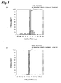
- Fig. 4 is a drawing for explaining the effect of the quantum beam generation device according to the embodiment.
- the horizontal axis in part (A) of Fig. 4 and the horizontal axis in part (B) of Fig. 4 both represent time jitter (ms).
- the time jitter shown in Fig. 4 is a value obtained by subtracting the passing time of the target 2a at the irradiation point 4d from the irradiation time thereof with the laser light 8a.
- the vertical axis in part (A) of Fig. 4 and the vertical axis in part (B) of Fig. 4 both represent frequency (event count).
- Part (A) of Fig. 4 is the measurement result obtained, particularly, without use of the laser control information 9e in the quantum beam generation device 1a.
- Part (B) of Fig. 4 is the measurement result of the quantum beam generation device 1a (particularly, the measurement result obtained with use of the laser control information 9e). It is understood from the measurement results shown in Fig. 4 that the quantum beam generation device 1a using the laser control information 9e shows the higher frequency of events that the irradiation time with the laser light 8a is approximately coincident with the passing time of the target 2a at the irradiation point 4d (or that the time jitter is zero) than the quantum beam generation device 1a not using the laser control information 9e. When the time jitter is zero, the laser light 8a is irradiated onto the target 2a.
- the target 2a to be used can be a shell or a bead containing Li or Be. When the shell or bead containing Li or Be is used as a target, the device can generate a quantum beam of neutrons, protons, ions, or the like.
- the target 2a to induce the quantum beam generation reaction is supplied at the timing for emitting, that is controlled by the controller 7a, to the inside of the chamber 3a by the target supply unit 4a, the motion of the target 2a inside the chamber 3a is monitored by the target monitor 5a, and the controller 7a implements the irradiation of the target 2a with the laser light 8a, based on the result of this monitoring. Therefore, the supply of the target 2a and the irradiation of the target 2a with the laser light 8a are automatically carried out by the controller 7a, whereby continuous quantum beam generation is enabled by the control by the controller 7a.
- the targets 2a By rotating the disc 10a on which the targets 2a are arranged at equal intervals, the targets 2a can be sequentially supplied to the chamber 3a. Therefore, periodic and continuous quantum beam generation can be realized with the use of the disc 10a on which the targets 2a are arranged at equal intervals.
- the controller 7a can recognize the rotating state of the disc 10a by use of the sensor 5c, the disc 10a can be rotated in an optionally set period. Therefore, it becomes feasible to implement continuous quantum beam generation in the optionally set period.
- the target 2a is forcibly emitted by the emission assist 3b, it allows us to avoid such an event that no emission is implemented despite arrival of the timing for emitting. Furthermore, since the target can be emitted at high speed, the target, when used as cooled at low temperature, can be supplied to the irradiation point within a short time while maintained at the temperature.
- any one or all of the target supply unit 4a, the time detector 6c, and the laser light irradiator 6a can be arranged outside the chamber 3a.
- a plurality of laser light output units 5d may be arranged so that the target can be irradiated simultaneously or with time difference.
- a material of the target is a pellet filled with a solid hydrogen isotope (deuterium or tritium) cooled at extremely low temperature, a pellet filled with a gas hydrogen isotope, or a plastic bead or plastic shell whose hydrogen is replaced with a hydrogen isotope
- the quantum beam generation device of the embodiment can serve as a laser fusion device (a device for laser fusion).
- the target supply unit 4a is arranged in an extremely-low-temperature bath in a thermally insulated state from the chamber 3a, whereby the target cooled at low temperature can be supplied. In this manner, the embodiment can provide the device for laser fusion and method for fusion generation, that are capable of implementing automatic continuous fusion reactions.
- the present invention is applicable to the device for quantum beam generation, the method for quantum beam generation, and the device for laser fusion capable of implementing the automatic continuous quantum beam generation.
- 1a... quantum beam generation device 2a... target; 3a chamber; 4a... target supply unit; 5a... target monitor; 6a... laser light irradiator; 7a... controller; 8a... laser light; 9a... support table; 10a... disc; 1b... tank; 2b... driver; 3b... emission assist; 4b... principal surface; 5b... back surface; 6b... through hole; 7b... edge; 8b... emission hole; 9b... emission port; 10b... center; 1c... main body; 2c... supply tube; 3c... motor; 4c... rotary shaft; 5c... sensor; 6c... time detector; 7c... position detector; 8c... light emitting device; 9c... light emitting device; 10c... light receiving device; 1d...
Landscapes
- Physics & Mathematics (AREA)
- Engineering & Computer Science (AREA)
- General Engineering & Computer Science (AREA)
- High Energy & Nuclear Physics (AREA)
- Plasma & Fusion (AREA)
- General Physics & Mathematics (AREA)
- X-Ray Techniques (AREA)
- Aiming, Guidance, Guns With A Light Source, Armor, Camouflage, And Targets (AREA)
- Optics & Photonics (AREA)
Abstract
Description
- The present invention relates to a device for quantum beam generation, a method for quantum beam generation, and a device for laser fusion.
-
Patent Literature 1 discloses a system for extracting energy from a controlled fusion reaction. This system includes a target chamber for receiving a fusion target material. A plurality of energy drivers are arranged around the target chamber so as to supply energy to the target material in the target chamber to initiate the controlled fusion reaction, releasing energy in the forms of fusion plasma and heat. The system is provided with a plurality of structures for extracting energy from the fusion reaction. These structures have devices to extract high-voltage electric current power from the fusion plasma; and means to extract thermal energy from the target chamber. Power to the energy drivers can be supplied from the high-voltage DC power extracted from the fusion reaction. The energy drivers use an apodizing filter to impart a desired shape to the wavefront of the driving energy for causing the fusion reaction, in order to avoid hydrodynamic instability. - Patent Literature 2 discloses a laser plasma EUV light source for irradiating a target with laser light to plasmanize the target and extracting EUV light generated on that occasion, as output. This laser plasma EUV light source uses a platelike target in a size approximately equal to a focused diameter of the laser light, as the target. The target is ejected with a direction of a disc aligned, from a nozzle having a slit-shaped aperture. The target is conveyed on a gas stream. He (helium) gas is used in this example. Since the exterior of the nozzle is maintained in a high vacuum, the target ejected from the nozzle reaches an irradiation position with the laser light, while keeping its posture unchanged. In synchronism with the supply of the target, pulsed laser light from an Nd:YAG laser light source is focused by a lens to be applied onto the target. The spot diameter of the laser is the same as the diameter of the target, 1 mm, and the thickness thereof is not more than 1000 nm. Therefore, almost the entire target is plasmanized, while inhibiting generation of debris and enhancing conversion efficiency.
-
Non Patent Literature 1 discloses a technology using a long target acceleration mechanism of a linear sabot type and air gun type. Non Patent Literature 2 discloses a technology of a target acceleration mechanism of a sabot type. -
- Patent Literature 1: Japanese Translation of PCT International Application Publication No. 2009-539117
- Patent Literature 2: Domestic Re-publication of PCT International Application No. 2006/075535
-
- Non Patent Literature 1: NORIMATSU Takayoshi, ENDO Takuma, YOSHIDA Hiroki, and IWAMOTO Akifumi, " 4. Design of Target Fabrication and Injection System," J. Plasma Fusion Res. Vol. 82, No. 12 (2006) 829-835
- Non Patent Literature 2: Catalog of GENERAL ATOMICS, "IFT Catalog," "11. INERTIAL FUSION ENERGY," URL:http://www.ga.com/media/GA/energy/IFT_Catalog.pdf
- The conventional devices for quantum beam generation as described above are not ones that can automatically continuously generate a quantum beam. Therefore, one of objects of the present invention, while having been accomplished in view of the above circumstances, is to provide a device for quantum beam generation, a method for quantum beam generation, and a device for laser fusion enabling automatic, continuous quantum beam generation, for example.
- A device for quantum beam generation according to one aspect of the present invention is one comprising: a chamber for a target to induce a quantum beam generation reaction; a target supply unit that supplies the target to the chamber; a target monitor that monitors the target present inside the chamber; a laser light irradiator that irradiates the target present inside the chamber, with laser light; and a controller that controls the target supply unit and the laser light irradiator, based on the result of the monitoring by the target monitor, wherein the target supply unit comprises an emission port that emits the target, and emits the target at a timing for emitting, that is controlled by the controller, into a preset emission direction inside the chamber from the emission port, wherein the target monitor comprises a position detector and a time detector, wherein the position detector detects a passing position of the target in a monitoring area and sends position information indicative of the passing position, to the controller, wherein the monitoring area is preliminarily set at a position where the monitoring area intersects with the emission direction inside the chamber, wherein the passing position indicates a position in a plane perpendicular to the emission direction, wherein the time detector measures an entrance time when the target enters the monitoring area and an exit time when the target exits the monitoring area, and sends entrance time information indicative of the entrance time and exit time information indicative of the exit time, to the controller, wherein the laser light irradiator comprises a laser light output unit and a condensing optical unit, wherein the laser light output unit outputs laser light under control of the controller, wherein the condensing optical unit condenses the laser light output from the laser light output unit, based on control by the controller, wherein the controller calculates an irradiation point with the laser light, using the position information, sends condensing control information based on the irradiation point to the condensing optical unit, calculates a timing for arriving of the target at the irradiation point, using a width of the monitoring area, the entrance time information, the exit time information, and a distance from the monitoring area to the irradiation point, and sends laser control information based on the timing for arriving, to the laser light output unit, wherein the condensing control information is information for controlling the condensing optical unit so as to condense the laser light from the laser light output unit to the irradiation point, and wherein the laser control information is information for controlling the laser light output unit so as to output the laser light at the timing for arriving. In this manner, the target supply unit supplies the target to induce the quantum beam generation reaction, at the timing for emitting, that is controlled by the controller, to the inside of the chamber, the target monitor monitors motion of the target inside the chamber, and the controller implements the irradiation of the target with the laser light, based on the result of this monitoring. Therefore, the controller automatically implements the supply of the target and the irradiation of the target with the laser light, whereby continuous quantum beam generation is enabled by the control by the controller.
- In the device for quantum beam generation according to the one aspect of the present invention, the controller controls the target supply unit so as to sequentially emit a plurality of the targets at periodic intervals from the emission port. Therefore, periodic continuous quantum beam generation is enabled by the control by the controller.
- In the device for quantum beam generation according to the one aspect of the present invention, the target supply unit comprises a support table, a disc, a tank, and a driver; the support table comprises a principal surface, a back surface, and an emission hole; the emission hole has a diameter enough for the target to pass, has the emission port, and penetrates from the principal surface to the back surface; the disc comprises a plurality of through holes at preset intervals along an edge of the disc; a center of the disc is held rotatable with respect to the principal surface so that the through holes can overlap with the emission hole; the through holes can enclose the targets on the principal surface; the tank comprises a main body and a supply tube and is arranged above the disc; the main body can store a plurality of the targets; the supply tube has a diameter enough for the target to pass, is connected to the main body, and is arranged above a circumference passing centers of all the through holes; the driver comprises a rotary shaft and a motor; the rotary shaft is fixed to the disc at the center of the disc and is rotatable along with the disc; and the motor is connected to the rotary shaft and rotates the rotary shaft under control of the controller. Therefore, the targets can be sequentially supplied to the chamber by rotating the disc on which the targets are arranged at equal intervals. Accordingly, periodic and continuous quantum beam generation can be realized by use of the disc on which the targets are arranged at equal intervals.
- In the device for quantum beam generation according to the one aspect of the present invention, the driver comprises a sensor; the sensor detects the number of rotations of the rotary shaft and an axial position of the rotary shaft, and sends to the controller, rotation information indicative of the number of rotations and the axial position; the controller controls rotary motion of the disc, based on the rotation information; and the axial position is a position in a rotating direction of the rotary shaft. In this manner, the rotating state of the disc can be recognized by use of the sensor and thus the controller can rotate the disc in an optionally set period. Therefore, continuous quantum beam generation can be performed in the optionally set period.
- In the device for quantum beam generation according to the one aspect of the present invention, the target supply unit comprises an emission assist; the emission assist is arranged above the emission hole and can press the target present at the emission hole toward the emission direction under control of the controller; the controller calculates a timing for pressing when the through hole of the disc overlaps with the emission hole with rotation of the disc, based on the rotation information, and sends press control information based on the timing for pressing, to the emission assist; and the press control information is information for controlling the emission assist so as to press the target at the timing for pressing. The target is forcibly emitted by the emission assist and thus it can avoid an event of failure in emission, despite arrival of the timing for emitting. Furthermore, since the target can be emitted at high speed, the target, when used as cooled at low temperature, can be supplied to the irradiation point within a short time while being maintained at the temperature.
- A method for quantum beam generation according to one aspect of the present invention is one comprising: an emission step of emitting a target to induce quantum beam generation, to an inside of a chamber; an estimation step of estimating an irradiation point with laser light inside the chamber; a preparation step of preparing irradiation with the laser light; and an output step of outputting the laser light, wherein the emission step comprises emitting the target at a controllable timing for emitting, into a preset emission direction inside the chamber, wherein the estimation step comprises detecting a passing position of the target in a monitoring area, measuring an entrance time when the target enters the monitoring area and an exit time when the target exits the monitoring area, calculating the irradiation point using the passing position, and calculating a timing for arriving of the target at the irradiation point, using a width of the monitoring area, the entrance time, the exit time, and a distance from the monitoring area to the irradiation point, wherein the monitoring area is preliminarily set at a position where the monitoring area intersects with the emission direction inside the chamber, wherein the passing position indicates a position in a plane perpendicular to the emission direction, wherein the preparation step comprises enabling the laser light to be condensed at the irradiation point, and wherein the output step comprises outputting the laser light at the timing for arriving. In this manner, the target to induce the quantum beam generation reaction is supplied at the controllable timing for emitting to the inside of the chamber, motion of the target inside the chamber is monitored, and the target is irradiated with the laser light, based on the result of this monitoring. Therefore, the supply of the target and the irradiation of the target with the laser light are automatically carried out, so as to enable continuous quantum beam generation.
- In the method for quantum beam generation according to the one aspect of the present invention, the emission step comprises sequentially emitting a plurality of the targets at periodic intervals. Therefore, it becomes feasible to implement periodic continuous quantum beam generation.
- A device for laser fusion according to one aspect of the present invention is one comprising: a chamber for a target to induce a fusion reaction; a target supply unit that supplies the target to the chamber; a target monitor that monitors the target present inside the chamber; a laser light irradiator that irradiates the target present inside the chamber, with laser light; and a controller that controls the target supply unit and the laser light irradiator, based on the result of the monitoring by the target monitor, wherein the target supply unit comprises an emission port that emits of the target, and emits the target at a timing for emitting, that is controlled by the controller, into a preset emission direction inside the chamber from the emission port, wherein the target monitor comprises a position detector and a time detector, wherein the position detector detects a passing position of the target in a monitoring area and sends position information indicative of the passing position, to the controller, wherein the monitoring area is preliminarily set at a position where the monitoring area intersects with the emission direction inside the chamber, wherein the passing position indicates a position in a plane perpendicular to the emission direction, wherein the time detector measures an entrance time when the target enters the monitoring area and an exit time when the target exits the monitoring area, and sends entrance time information indicative of the entrance time and exit time information indicative of the exit time, to the controller, wherein the laser light irradiator comprises a laser light output unit and a condensing optical unit, wherein the laser light output unit outputs laser light under control of the controller, wherein the condensing optical unit condenses the laser light output from the laser light output unit, based on control by the controller, wherein the controller calculates an irradiation point with the laser light, using the position information, sends condensing control information based on the irradiation point to the condensing optical unit, calculates a timing for arriving of the target at the irradiation point, using a width of the monitoring area, the entrance time information, the exit time information, and a distance from the monitoring area to the irradiation point, and sends laser control information based on the timing for arriving, to the laser light output unit, wherein the condensing control information is information for controlling the condensing optical unit so as to condense the laser light from the laser light output unit to the irradiation point, wherein the laser control information is information for controlling the laser light output unit so as to output the laser light at the timing for arriving, and wherein a material of the target is a material containing a hydrogen isotope. In this manner, the target supply unit supplies the target to induce the fusion reaction, at the timing for emitting, that is controlled by the controller, to the inside of the chamber, the target monitor monitors motion of the target inside the chamber, and the controller implements the irradiation of the target with the laser light, based on the result of this monitoring. Therefore, the controller automatically implements the supply of the target and the irradiation of the target with the laser light, whereby continuous fusion reactions are enabled by the control by the controller.
- One aspect of the present invention can provide the device for quantum beam generation and the method for quantum beam generation, that are capable of implementing automatic, continuous quantum beam generation, and the device for laser fusion.
-
-
Fig. 1 is a drawing schematically showing a configuration of a device for quantum beam generation according to an embodiment. -
Fig. 2 is a drawing schematically showing the configuration of the device for quantum beam generation according to the embodiment. -
Fig. 3 is a flowchart for explaining a method for quantum beam generation according to an embodiment. -
Fig. 4 is a drawing for explaining an effect of the device for quantum beam generation according to the embodiment. - Embodiments will be described below in detail with reference to the drawings. In the description of the drawings the same elements will be denoted by the same reference signs as much as possible, without redundant description. The configuration of quantum beam generation device 1a (device for quantum beam generation) according to an embodiment will be described with reference to
Figs. 1 and2 .Figs. 1 and2 are drawings both schematically showing the configuration of the quantum beam generation device 1a. - The quantum beam generation device 1a has a
chamber 3a, atarget supply unit 4a, atarget monitor 5a, alaser light irradiator 6a, and acontroller 7a. Thechamber 3a defines a space where atarget 2a induces a quantum beam generation reaction. Thetarget supply unit 4a supplies thetarget 2a to thechamber 3a. Thetarget monitor 5a monitors thetarget 2a present inside thechamber 3a. Thelaser light irradiator 6a irradiates thetarget 2a present inside thechamber 3a, withlaser light 8a. Thecontroller 7a controls thetarget supply unit 4a and thelaser light irradiator 6a, based on the result of monitoring by thetarget monitor 5a. - The
target supply unit 4a has anemission port 9b that emits thetarget 2a. Thetarget supply unit 4a supplies thetarget 2a at a timing for emitting, that is controlled by thecontroller 7a, into apreset emission direction 3d inside thechamber 3a from theemission port 9b. - The
target supply unit 4a has a support table 9a, adisc 10a, atank 1b, and adriver 2b. The support table 9a has aprincipal surface 4b, aback surface 5b, and anemission hole 8b. Theemission hole 8b has the diameter enough for thetarget 2a to pass. Theemission hole 8b has theemission port 9b. Theemission hole 8b penetrates from theprincipal surface 4b to theback surface 5b. Theemission port 9b is an aperture on theback surface 5b side. - The
disc 10a has a plurality of throughholes 6b at preset intervals (e.g., at equal intervals) along theedge 7b of thedisc 10a. Acenter 10b of thedisc 10a is held rotatable with respect to theprincipal surface 4b so that the throughholes 6b can overlap with theemission hole 8b. The throughholes 6b can enclose therespective targets 2a on theprincipal surface 4b. - The
tank 1b has amain body 1c and asupply tube 2c. Thetank 1b is arranged above thedisc 10a. Themain body 1c can store a plurality oftargets 2a. Thesupply tube 2c has the diameter enough for thetarget 2a to pass. Thesupply tube 2c is connected to themain body 1c. Thesupply tube 2c is arranged above a circumference 10b1 passing centers of all the throughholes 6b. - The
driver 2b has arotary shaft 4c and amotor 3c. Therotary shaft 4c is fixed to thedisc 10a at thecenter 10b of thedisc 10a and is rotatable along with thedisc 10a. Themotor 3c is connected to therotary shaft 4c. Themotor 3c rotates therotary shaft 4c under control of thecontroller 7a. - The
driver 2b has a sensor 5c. The sensor 5c detects the number of rotations of therotary shaft 4c and the axial position of therotary shaft 4c. The sensor 5c sends to thecontroller 7a,rotation information 1e indicative of the number of rotations of therotary shaft 4c and the axial position of therotary shaft 4c. The axial position of therotary shaft 4c is a position in a rotating direction of therotary shaft 4c. In the present embodiment, information means electronic data that a CPU of thecontroller 7a can read. - The
target supply unit 4a has anemission assist 3b. Theemission assist 3b is arranged above theemission hole 8b. Theemission assist 3b can press thetarget 2a present above theemission hole 8b, toward theemission direction 3d under control of thecontroller 7a. The emission assist 3b presses thetarget 2a, for example, by ejecting gas toward theemission direction 3d. - The
target monitor 5a has aposition detector 7c and atime detector 6c. Theposition detector 7c consists of, for example, one or more imaging devices (cameras). Theposition detector 7c detects a passing position of thetarget 2a in amonitoring area 2d and sendsposition information 6e indicative of this passing position to thecontroller 7a. Theposition detector 7c detects the passing position of thetarget 2a at a timing when thetarget 2a enters themonitoring area 2d, for example, based onentrance time information 4e. Themonitoring area 2d is preliminarily set at a position where the monitoring area intersects with theemission direction 3d inside thechamber 3a. The passing position detected by theposition detector 7c indicates a position in a plane perpendicular to theemission direction 3d (or in a plane parallel to areference plane 3f shown inFig. 2 ). Thetime detector 6c measures an entrance time when thetarget 2a enters themonitoring area 2d, and an exit time when thetarget 2a exits themonitoring area 2d. - The
time detector 6c sends to thecontroller 7a, theentrance time information 4e indicative of the entrance time andexit time information 5e indicative of the exit time. Thetime detector 6c is, for example, a photosensor. Thetime detector 6c has alight emitting device 8c, alight emitting device 9c, alight receiving device 10c, and alight receiving device 1d. Thelight receiving device 10c receives light emitted from thelight emitting device 8c. Thelight receiving device 1d receives light emitted from thelight emitting device 9c. Thelight receiving device 10c converts the received light signal into an electric signal and sends this electric signal asentrance time information 4e to thecontroller 7a. Thelight receiving device 1d converts the received light signal into an electric signal and sends this electric signal asexit time information 5e to thecontroller 7a. Themonitoring area 2d is defined by a travel path of the light emitted from thelight emitting device 8c and a travel path of the light emitted from thelight emitting device 9c. When thetarget 2a enters themonitoring area 2d, the electric signal (entrance time information 4e) output by thelight receiving device 10c takes a value indicative of entrance of thetarget 2a into themonitoring area 2d. When thetarget 2a exits themonitoring area 2d, the electric signal (exit time information 5e) output by thelight receiving device 1d takes a value indicative of exit of thetarget 2a from themonitoring area 2d. Thelight emitting device 8c and thelight emitting device 9c both are, for example, light emitting diodes. Thelight receiving device 10c and thelight receiving device 1d both are, for example, photodiodes. Here, thetime detector 6c may be a plurality of imaging devices or an imaging device that is capable of high-speed photography. - The
laser light irradiator 6a has a laserlight output unit 5d and a condensingoptical unit 6d. The laserlight output unit 5d outputslaser light 8a under control of thecontroller 7a. The laserlight output unit 5d has alaser light source 9d and ashutter 10d. Thelaser light source 9d emits the laser light at a repetition rate of several ten MHz, irrespective oflaser control information 9e. The laserlight output unit 5d selects laser pulses from a laser pulse train of pulse emissions at the repetition rate of several ten MHz, based on thelaser control information 9e, and drives theshutter 10d. The laserlight output unit 5d opens theshutter 10d with instructions of emission and closes theshutter 10d with instructions of no emission, based on thelaser control information 9e. - The condensing
optical unit 6d condenses thelaser light 8a output from the laserlight output unit 5d, based on control by thecontroller 7a. The condensingoptical unit 6d has a plurality of mirrors, e.g.,mirror 7d andmirror 8d. The condensingoptical unit 6d moves arrangements, for example, of themirror 7d and themirror 8d, based on condensingcontrol information 8e. - The
controller 7a calculates a timing (timing for pressing) when each throughhole 6b of thedisc 10a overlaps with theemission hole 8b during rotation of thedisc 10a, based on therotation information 1e. Thecontroller 7a sends press control information 3e based on the timing for pressing, to the emission assist 3b. The press control information 3e is information for controlling the emission assist 3b so as to press the target at the timing for pressing, that is calculated by thecontroller 7a. - The
controller 7a controls thetarget supply unit 4a so as to sequentially emit a plurality oftargets 2a at periodic intervals from theemission port 9b. Thecontroller 7a controls the rotary motion of thedisc 10a, based on therotation information 1e. - The
controller 7a calculates anirradiation point 4d with thelaser light 8a, using theposition information 6e. Theirradiation point 4d is a point included in thereference plane 3f. Thereference plane 3f is a plane a distance of which is constant from theprincipal surface 4b of the support table 9a (the distance is the sum ofdistance 10e, width If, anddistance 2f) and which is perpendicular to theemission direction 3d. Thecontroller 7a sends the condensingcontrol information 8e based on theirradiation point 4d, to the condensingoptical unit 6d. Thecontroller 7 a calculates a timing for arriving of thetarget 2a at theirradiation point 4d, using thewidth 1f of themonitoring area 2d, theentrance time information 4e, theexit time information 5e, and thedistance 2f from themonitoring area 2d to theirradiation point 4d. Thecontroller 7 a sends thelaser control information 9e based on the timing for arriving, to the laserlight output unit 5d. The condensingcontrol information 8e is information for controlling the condensingoptical unit 6d so as to condense thelaser light 8a from the laserlight output unit 5d, to theirradiation point 4d. Thelaser control information 9e is information for controlling the laserlight output unit 5d so as to output thelaser light 8a at the timing for arriving, that is calculated by thecontroller 7a. All pieces of the information indicative of thedistance 10e, the information indicative of the width If, and the information indicative of thedistance 2f are preliminarily stored as electronic data in a memory of thecontroller 7a. - The diameter of the
emission hole 8b is, for example, not less than 101% and not more than 120% of the diameter of thetarget 2a. The diameter of thesupply tube 2c is, for example, not less than 101% and not more than 120% of the diameter of thetarget 2a. Thecontroller 7a implements emissions of thetargets 2a, for example, in the range of not less than 10 Hz and not more than 100 Hz. Theemission assist 3b can set the initial velocity of thetarget 2a upon emission from theemission port 9b, for example, in the range of not less than several m/s and not more than several hundred m/s. Theemission assist 3b ejects gas toward theemission direction 3d, for example, only in a period of not less than several ms and not more than several hundred ms, so as to press thetarget 2a. Thedistance 10e is, for example, approximately 80 mm, the width If, for example, approximately 40 mm, and thedistance 2f, for example, approximately 60 mm. - A method for quantum beam generation according to an embodiment will be described with reference to
Fig. 3 . First, in step S1 (emission step), thecontroller 7a controls thetarget supply unit 4a to emit thetarget 2a to the inside of thechamber 3a. In step S1, thecontroller 7a controls thetarget supply unit 4a to emit thetarget 2a at the timing for emitting, that can be controlled by thecontroller 7a, into thepreset emission direction 3d inside thechamber 3a. - After step S1, step S2 (estimation step) is carried out so that the
controller 7a estimates theirradiation point 4d with thelaser light 8a inside thechamber 3a. The step S2 consists of step S2a and step S2b. - In step S2a, the
position detector 7c detects the passing position of thetarget 2a in themonitoring area 2d. In step S2a, thetime detector 6c measures the entrance time when thetarget 2a enters themonitoring area 2d, and the exit time when thetarget 2a exits themonitoring area 2d. - After step S2a, step S2b is carried out so that the
position detector 7c calculates theirradiation point 4d, using the passing position detected by theposition detector 7c. In step S2b, theposition detector 7c calculates the timing for arriving of thetarget 2a at theirradiation point 4d, using thewidth 1f of themonitoring area 2d, theentrance time information 4e indicative of the entrance time, theexit time information 5e indicative of the exit time, and thedistance 2f from themonitoring area 2d to theemission point 4d. - After step S2, step S3 (preparation step) is carried out so that the
controller 7a controls the condensingoptical unit 6d to move the irradiation position with thelaser light 8a so as to condense thelaser light 8a at theirradiation point 4d, thereby preparing the irradiation. After step S3, step S4 (output step) is carried out so that thecontroller 7a controls the laserlight output unit 5d to output thelaser light 8a at the arrival time calculated in step S2b. -
Fig. 4 is a drawing for explaining the effect of the quantum beam generation device according to the embodiment. The horizontal axis in part (A) ofFig. 4 and the horizontal axis in part (B) ofFig. 4 both represent time jitter (ms). The time jitter shown inFig. 4 is a value obtained by subtracting the passing time of thetarget 2a at theirradiation point 4d from the irradiation time thereof with thelaser light 8a. The vertical axis in part (A) ofFig. 4 and the vertical axis in part (B) ofFig. 4 both represent frequency (event count). Part (A) ofFig. 4 is the measurement result obtained, particularly, without use of thelaser control information 9e in the quantum beam generation device 1a. Part (B) ofFig. 4 is the measurement result of the quantum beam generation device 1a (particularly, the measurement result obtained with use of thelaser control information 9e). It is understood from the measurement results shown inFig. 4 that the quantum beam generation device 1a using thelaser control information 9e shows the higher frequency of events that the irradiation time with thelaser light 8a is approximately coincident with the passing time of thetarget 2a at theirradiation point 4d (or that the time jitter is zero) than the quantum beam generation device 1a not using thelaser control information 9e. When the time jitter is zero, thelaser light 8a is irradiated onto thetarget 2a. Thetarget 2a to be used can be a shell or a bead containing Li or Be. When the shell or bead containing Li or Be is used as a target, the device can generate a quantum beam of neutrons, protons, ions, or the like. - In this manner, the
target 2a to induce the quantum beam generation reaction is supplied at the timing for emitting, that is controlled by thecontroller 7a, to the inside of thechamber 3a by thetarget supply unit 4a, the motion of thetarget 2a inside thechamber 3a is monitored by thetarget monitor 5a, and thecontroller 7a implements the irradiation of thetarget 2a with thelaser light 8a, based on the result of this monitoring. Therefore, the supply of thetarget 2a and the irradiation of thetarget 2a with thelaser light 8a are automatically carried out by thecontroller 7a, whereby continuous quantum beam generation is enabled by the control by thecontroller 7a. - By the control by the
controller 7a, it becomes feasible to implement periodic continuous quantum beam generation. - By rotating the
disc 10a on which thetargets 2a are arranged at equal intervals, thetargets 2a can be sequentially supplied to thechamber 3a. Therefore, periodic and continuous quantum beam generation can be realized with the use of thedisc 10a on which thetargets 2a are arranged at equal intervals. - Since the
controller 7a can recognize the rotating state of thedisc 10a by use of the sensor 5c, thedisc 10a can be rotated in an optionally set period. Therefore, it becomes feasible to implement continuous quantum beam generation in the optionally set period. - Since the
target 2a is forcibly emitted by the emission assist 3b, it allows us to avoid such an event that no emission is implemented despite arrival of the timing for emitting. Furthermore, since the target can be emitted at high speed, the target, when used as cooled at low temperature, can be supplied to the irradiation point within a short time while maintained at the temperature. - The principle of the present invention was shown and described above with the preferred embodiments, and it is to be understood by those skilled in the art that the present invention can be modified in arrangement and details without departing from the principle. The present invention is by no means intended to be limited to the specific configurations disclosed in the embodiments. Therefore, rights are claimed to all corrections and modifications coming from the scope of claims and the scope of spirit thereof. For example, any one or all of the
target supply unit 4a, thetime detector 6c, and thelaser light irradiator 6a can be arranged outside thechamber 3a. - A plurality of laser
light output units 5d may be arranged so that the target can be irradiated simultaneously or with time difference. When a material of the target is a pellet filled with a solid hydrogen isotope (deuterium or tritium) cooled at extremely low temperature, a pellet filled with a gas hydrogen isotope, or a plastic bead or plastic shell whose hydrogen is replaced with a hydrogen isotope, the quantum beam generation device of the embodiment can serve as a laser fusion device (a device for laser fusion). When the device is used as a laser fusion device, thetarget supply unit 4a is arranged in an extremely-low-temperature bath in a thermally insulated state from thechamber 3a, whereby the target cooled at low temperature can be supplied. In this manner, the embodiment can provide the device for laser fusion and method for fusion generation, that are capable of implementing automatic continuous fusion reactions. - The present invention is applicable to the device for quantum beam generation, the method for quantum beam generation, and the device for laser fusion capable of implementing the automatic continuous quantum beam generation.
- 1a... quantum beam generation device; 2a... target; 3a chamber; 4a... target supply unit; 5a... target monitor; 6a... laser light irradiator; 7a... controller; 8a... laser light; 9a... support table; 10a... disc; 1b... tank; 2b... driver; 3b... emission assist; 4b... principal surface; 5b... back surface; 6b... through hole; 7b... edge; 8b... emission hole; 9b... emission port; 10b... center; 1c... main body; 2c... supply tube; 3c... motor; 4c... rotary shaft; 5c... sensor; 6c... time detector; 7c... position detector; 8c... light emitting device; 9c... light emitting device; 10c... light receiving device; 1d... light receiving device; 2d... monitoring area; 3d... emission direction; 4d... irradiation point; 5d... laser light output unit; 6d... condensing optical unit; 7d... mirror; 8d mirror; 9d... laser light source; 10d... shutter; 1e... rotation information; 2e... rotation control information; 3e... press control information; 4e... entrance time information; 5e... exit time information; 6e... position information; 7e... imaging control information; 8e... condensing control information; 9e... laser control information; 10e... distance; 1f... width; 2f... distance; 3f... reference plane.
Claims (8)
- A device for quantum beam generation, comprising:a chamber for a target to induce a quantum beam generation reaction;a target supply unit that supplies the target to the chamber;a target monitor that monitors the target present inside the chamber;a laser light irradiator that irradiates the target present inside the chamber, with laser light; anda controller that controls the target supply unit and the laser light irradiator, based on the result of the monitoring by the target monitor,wherein the target supply unit comprises an emission port that emits the target, and emits the target at a timing for emitting, that is controlled by the controller, into a preset emission direction inside the chamber from the emission port,wherein the target monitor comprises a position detector and a time detector,wherein the position detector detects a passing position of the target in a monitoring area and sends position information indicative of the passing position, to the controller,wherein the monitoring area is preliminarily set at a position where the monitoring area intersects with the emission direction inside the chamber,wherein the passing position indicates a position in a plane perpendicular to the emission direction,wherein the time detector measures an entrance time when the target enters the monitoring area and an exit time when the target exits the monitoring area, and sends entrance time information indicative of the entrance time and exit time information indicative of the exit time, to the controller,wherein the laser light irradiator comprises a laser light output unit and a condensing optical unit,wherein the laser light output unit outputs laser light under control of the controller,wherein the condensing optical unit condenses the laser light output from the laser light output unit, based on control by the controller,wherein the controller calculates an irradiation point with the laser light, using the position information, sends condensing control information based on the irradiation point to the condensing optical unit, calculates a timing for arriving of the target at the irradiation point, using a width of the monitoring area, the entrance time information, the exit time information, and a distance from the monitoring area to the irradiation point, and sends laser control information based on the timing for arriving, to the laser light output unit,wherein the condensing control information is information for controlling the condensing optical unit so as to condense the laser light from the laser light output unit to the irradiation point, andwherein the laser control information is information for controlling the laser light output unit so as to output the laser light at the timing for arriving.
- The device for quantum beam generation according to claim 1, wherein the controller controls the target supply unit so as to sequentially emit a plurality of the targets at periodic intervals from the emission port.
- The device for quantum beam generation according to claim 1 or claim 2,
wherein the target supply unit comprises a support table, a disc, a tank, and a driver,
wherein the support table comprises a principal surface, a back surface, and an emission hole,
wherein the emission hole has a diameter enough for the target to pass, has the emission port, and penetrates from the principal surface to the back surface,
wherein the disc comprises a plurality of through holes at preset intervals along an edge of the disc,
wherein a center of the disc is held rotatable with respect to the principal surface so that the through holes can overlap with the emission hole,
wherein the through holes can enclose the targets on the principal surface,
wherein the tank comprises a main body and a supply tube and is arranged above the disc,
wherein the main body can store a plurality of the targets, wherein the supply tube has a diameter enough for the target to pass, is connected to the main body, and is arranged above a circumference passing centers of all the through holes,
wherein the driver comprises a rotary shaft and a motor,
wherein the rotary shaft is fixed to the disc at the center of the disc and is rotatable along with the disc, and
wherein the motor is connected to the rotary shaft and rotates the rotary shaft under control of the controller. - The device for quantum beam generation according to claim 3,
wherein the driver comprises a sensor,
wherein the sensor detects the number of rotations of the rotary shaft and an axial position of the rotary shaft, and sends to the controller, rotation information indicative of the number of rotations and the axial position,
wherein the controller controls rotary motion of the disc, based on the rotation information, and
wherein the axial position is a position in a rotating direction of the rotary shaft. - The device for quantum beam generation according to claim 4,
wherein the target supply unit comprises an emission assist,
wherein the emission assist is arranged above the emission hole and can press the target present at the emission hole toward the emission direction under control of the controller,
wherein the controller calculates a timing for pressing when the through hole of the disc overlaps with the emission hole with rotation of the disc, based on the rotation information, and sends press control information based on the timing for pressing, to the emission assist, and
wherein the press control information is information for controlling the emission assist so as to press the target at the timing for pressing. - A method for quantum beam generation, comprising:an emission step of emitting a target to induce quantum beam generation, to an inside of a chamber;an estimation step of estimating an irradiation point with laser light inside the chamber;a preparation step of preparing irradiation with the laser light; andan output step of outputting the laser light,wherein the emission step comprises emitting the target at a controllable timing for emitting, into a preset emission direction inside the chamber,wherein the estimation step comprises detecting a passing position of the target in a monitoring area, measuring an entrance time when the target enters the monitoring area and an exit time when the target exits the monitoring area, calculating the irradiation point using the passing position, and calculating a timing for arriving of the target at the irradiation point, using a width of the monitoring area, the entrance time, the exit time, and a distance from the monitoring area to the irradiation point,wherein the monitoring area is preliminarily set at a position where the monitoring area intersects with the emission direction inside the chamber,wherein the passing position indicates a position in a plane perpendicular to the emission direction,wherein the preparation step comprises enabling the laser light to be condensed at the irradiation point, andwherein the output step comprises outputting the laser light at the timing for arriving.
- The method for quantum beam generation according to claim 6, wherein the emission step comprises sequentially emitting a plurality of the targets at periodic intervals.
- A device for laser fusion, comprising:a chamber for a target to induce a fusion reaction;a target supply unit that supplies the target to the chamber;a target monitor that monitors the target present inside the chamber;a laser light irradiator that irradiates the target present inside the chamber, with laser light; anda controller that controls the target supply unit and the laser light irradiator, based on the result of the monitoring by the target monitor,wherein the target supply unit comprises an emission port that emits of the target, and emits the target at a timing for emitting, that is controlled by the controller, into a preset emission direction inside the chamber from the emission port,wherein the target monitor comprises a position detector and a time detector,wherein the position detector detects a passing position of the target in a monitoring area and sends position information indicative of the passing position, to the controller,wherein the monitoring area is preliminarily set at a position where the monitoring area intersects with the emission direction inside the chamber,wherein the passing position indicates a position in a plane perpendicular to the emission direction,wherein the time detector measures an entrance time when the target enters the monitoring area and an exit time when the target exits the monitoring area, and sends entrance time information indicative of the entrance time and exit time information indicative of the exit time, to the controller,wherein the laser light irradiator comprises a laser light output unit and a condensing optical unit,wherein the laser light output unit outputs laser light under control of the controller,wherein the condensing optical unit condenses the laser light output from the laser light output unit, based on control by the controller,wherein the controller calculates an irradiation point with the laser light, using the position information, sends condensing control information based on the irradiation point to the condensing optical unit, calculates a timing for arriving of the target at the irradiation point, using a width of the monitoring area, the entrance time information, the exit time information, and a distance from the monitoring area to the irradiation point, and sends laser control information based on the timing for arriving, to the laser light output unit,wherein the condensing control information is information for controlling the condensing optical unit so as to condense the laser light from the laser light output unit to the irradiation point,wherein the laser control information is information for controlling the laser light output unit so as to output the laser light at the timing for arriving, andwherein a material of the target is a material containing a hydrogen isotope.
Applications Claiming Priority (2)
| Application Number | Priority Date | Filing Date | Title |
|---|---|---|---|
| JP2012258815A JP6010438B2 (en) | 2012-11-27 | 2012-11-27 | Quantum beam generating apparatus, quantum beam generating method, and laser fusion apparatus |
| PCT/JP2013/077120 WO2014083940A1 (en) | 2012-11-27 | 2013-10-04 | Device for quantum beam generation, method for quantum beam generation, and device for laser fusion |
Publications (3)
| Publication Number | Publication Date |
|---|---|
| EP2927909A1 true EP2927909A1 (en) | 2015-10-07 |
| EP2927909A4 EP2927909A4 (en) | 2016-07-27 |
| EP2927909B1 EP2927909B1 (en) | 2018-09-12 |
Family
ID=50827586
Family Applications (1)
| Application Number | Title | Priority Date | Filing Date |
|---|---|---|---|
| EP13857800.0A Active EP2927909B1 (en) | 2012-11-27 | 2013-10-04 | Device for quantum beam generation, method for quantum beam generation, and device for laser fusion |
Country Status (6)
| Country | Link |
|---|---|
| US (1) | US10134492B2 (en) |
| EP (1) | EP2927909B1 (en) |
| JP (1) | JP6010438B2 (en) |
| KR (1) | KR102071098B1 (en) |
| CN (1) | CN104813412B (en) |
| WO (1) | WO2014083940A1 (en) |
Families Citing this family (3)
| Publication number | Priority date | Publication date | Assignee | Title |
|---|---|---|---|---|
| CN105489262B (en) * | 2015-12-29 | 2017-09-22 | 中国科学院西安光学精密机械研究所 | Universal point light source simulation system |
| US10477663B2 (en) | 2017-11-16 | 2019-11-12 | Taiwan Semiconductor Manufacturing Co., Ltd. | Light source for lithography exposure process |
| US10802405B2 (en) | 2018-07-27 | 2020-10-13 | Taiwan Semiconductor Manufacturing Co., Ltd. | Radiation source for lithography exposure process |
Family Cites Families (20)
| Publication number | Priority date | Publication date | Assignee | Title |
|---|---|---|---|---|
| JPS5217789A (en) * | 1975-04-28 | 1977-02-09 | Tadashi Sekiguchi | High temperature plasma generation method device using laser beams |
| US7439530B2 (en) * | 2005-06-29 | 2008-10-21 | Cymer, Inc. | LPP EUV light source drive laser system |
| US8653437B2 (en) * | 2010-10-04 | 2014-02-18 | Cymer, Llc | EUV light source with subsystem(s) for maintaining LPP drive laser output during EUV non-output periods |
| JP3698677B2 (en) * | 2002-03-15 | 2005-09-21 | 川崎重工業株式会社 | Laser pulse control method and apparatus, and X-ray generation method and apparatus |
| KR100545294B1 (en) | 2002-05-10 | 2006-01-24 | 에이에스엠엘 네델란즈 비.브이. | Lithographic apparatus, device manufacturing methods, performance measurement methods, calibration methods and computer programs |
| US6977383B2 (en) * | 2003-01-02 | 2005-12-20 | Jmar Research, Inc. | Method and apparatus for generating a membrane target for laser produced plasma |
| EP1606980B1 (en) * | 2003-03-18 | 2010-08-04 | Philips Intellectual Property & Standards GmbH | Device for and method of generating extreme ultraviolet and/or soft x-ray radiation by means of a plasma |
| US7164144B2 (en) * | 2004-03-10 | 2007-01-16 | Cymer Inc. | EUV light source |
| JP2005334926A (en) | 2004-05-26 | 2005-12-08 | Yamazaki Mazak Corp | Nozzle presetter of laser beam machining tool in laser beam machine |
| DE102004037521B4 (en) * | 2004-07-30 | 2011-02-10 | Xtreme Technologies Gmbh | Device for providing target material for generating short-wave electromagnetic radiation |
| JP4560359B2 (en) | 2004-09-13 | 2010-10-13 | オリンパス株式会社 | Position detection apparatus, in-subject introduction system, and position detection method |
| JP4642618B2 (en) * | 2005-09-22 | 2011-03-02 | 株式会社小松製作所 | Extreme ultraviolet light source device |
| JP5156192B2 (en) * | 2006-01-24 | 2013-03-06 | ギガフォトン株式会社 | Extreme ultraviolet light source device |
| DE102006017904B4 (en) * | 2006-04-13 | 2008-07-03 | Xtreme Technologies Gmbh | Arrangement for generating extreme ultraviolet radiation from an energy beam generated plasma with high conversion efficiency and minimal contamination |
| US9036765B2 (en) | 2006-05-30 | 2015-05-19 | Advanced Fusion Systems Llc | Method and system for inertial confinement fusion reactions |
| US8228507B2 (en) * | 2007-08-18 | 2012-07-24 | Japan Science And Technology Agency | Quantum entanglement generating system and method, and quantum entanglement generating and detecting system and method |
| DE102008051083A1 (en) * | 2008-10-09 | 2010-04-15 | Dr. Johannes Heidenhain Gmbh | Multi-turn encoders |
| JP5612579B2 (en) * | 2009-07-29 | 2014-10-22 | ギガフォトン株式会社 | Extreme ultraviolet light source device, control method of extreme ultraviolet light source device, and recording medium recording the program |
| JP2012199512A (en) * | 2011-03-10 | 2012-10-18 | Gigaphoton Inc | Extreme ultraviolet light generation apparatus and extreme ultraviolet light generation method |
| JP6048790B2 (en) * | 2012-06-08 | 2016-12-21 | 国立研究開発法人理化学研究所 | Charged particle beam nozzle, generation method, and generation system |
-
2012
- 2012-11-27 JP JP2012258815A patent/JP6010438B2/en active Active
-
2013
- 2013-10-04 WO PCT/JP2013/077120 patent/WO2014083940A1/en not_active Ceased
- 2013-10-04 US US14/646,765 patent/US10134492B2/en active Active
- 2013-10-04 EP EP13857800.0A patent/EP2927909B1/en active Active
- 2013-10-04 CN CN201380061797.XA patent/CN104813412B/en active Active
- 2013-10-04 KR KR1020157016458A patent/KR102071098B1/en active Active
Also Published As
| Publication number | Publication date |
|---|---|
| KR20150088284A (en) | 2015-07-31 |
| KR102071098B1 (en) | 2020-01-29 |
| WO2014083940A1 (en) | 2014-06-05 |
| US20150294744A1 (en) | 2015-10-15 |
| JP2014106093A (en) | 2014-06-09 |
| CN104813412B (en) | 2017-03-29 |
| EP2927909B1 (en) | 2018-09-12 |
| JP6010438B2 (en) | 2016-10-19 |
| CN104813412A (en) | 2015-07-29 |
| US10134492B2 (en) | 2018-11-20 |
| EP2927909A4 (en) | 2016-07-27 |
Similar Documents
| Publication | Publication Date | Title |
|---|---|---|
| US10057972B2 (en) | Extreme ultraviolet light generation system and method of generating extreme ultraviolet light | |
| US9241395B2 (en) | System and method for controlling droplet timing in an LPP EUV light source | |
| EP2951643B1 (en) | Euv light source using cryogenic droplet targets in mask inspection | |
| US8809823B1 (en) | System and method for controlling droplet timing and steering in an LPP EUV light source | |
| US7482609B2 (en) | LPP EUV light source drive laser system | |
| US9497840B2 (en) | System and method for creating and utilizing dual laser curtains from a single laser in an LPP EUV light source | |
| US7439530B2 (en) | LPP EUV light source drive laser system | |
| KR102292882B1 (en) | Target for laser produced plasma extreme ultraviolet light source | |
| US8993976B2 (en) | Energy sensors for light beam alignment | |
| KR102458056B1 (en) | Technology to reduce the effect of plasma on an object in an extreme ultraviolet light source | |
| US10134492B2 (en) | Device for quantum beam generation, method for quantum beam generation, and device for laser fusion | |
| EP0474011B1 (en) | Method and apparatus for generating X rays | |
| US9426872B1 (en) | System and method for controlling source laser firing in an LPP EUV light source | |
| EP3163320B1 (en) | System and method for tracking and vaporizing objects in space | |
| US20160135276A1 (en) | Extreme ultraviolet light generation apparatus and extreme ultraviolet light generation system | |
| KR101415025B1 (en) | X-ray generator and X-ray photograph apparatus | |
| US20140209819A1 (en) | Target supply device and euv light generation chamber | |
| US8742380B2 (en) | Target supply device, extreme ultraviolet light generation apparatus, and method for supplying target | |
| US9860967B2 (en) | Target supply apparatus, extreme ultraviolet light generating apparatus, and target supply method | |
| Gershuni et al. | Automated delivery of microfabricated targets for intense laser irradiation experiments | |
| WO2017103980A1 (en) | Extreme ultraviolet light generating device | |
| US20250174956A1 (en) | Laser system and method for providing a pulsed laser beam intended for interaction with a target material | |
| JP6058329B2 (en) | X-ray source holding apparatus and X-ray diagnostic apparatus | |
| JP2012209182A (en) | Extreme ultraviolet light source apparatus | |
| Oishi et al. | Bremsstrahlung γ-ray generation by electrons from gas jets irradiated by laser pulses for radiographic testing |
Legal Events
| Date | Code | Title | Description |
|---|---|---|---|
| PUAI | Public reference made under article 153(3) epc to a published international application that has entered the european phase |
Free format text: ORIGINAL CODE: 0009012 |
|
| 17P | Request for examination filed |
Effective date: 20150622 |
|
| AK | Designated contracting states |
Kind code of ref document: A1 Designated state(s): AL AT BE BG CH CY CZ DE DK EE ES FI FR GB GR HR HU IE IS IT LI LT LU LV MC MK MT NL NO PL PT RO RS SE SI SK SM TR |
|
| AX | Request for extension of the european patent |
Extension state: BA ME |
|
| RAP1 | Party data changed (applicant data changed or rights of an application transferred) |
Owner name: TOYOTA JIDOSHA KABUSHIKI KAISHA Owner name: HAMAMATSU PHOTONICS K.K. |
|
| DAX | Request for extension of the european patent (deleted) | ||
| RA4 | Supplementary search report drawn up and despatched (corrected) |
Effective date: 20160627 |
|
| RIC1 | Information provided on ipc code assigned before grant |
Ipc: G21B 1/03 20060101ALI20160621BHEP Ipc: G21B 1/23 20060101ALI20160621BHEP Ipc: G21K 5/04 20060101AFI20160621BHEP Ipc: G21K 5/10 20060101ALI20160621BHEP |
|
| 17Q | First examination report despatched |
Effective date: 20171006 |
|
| GRAP | Despatch of communication of intention to grant a patent |
Free format text: ORIGINAL CODE: EPIDOSNIGR1 |
|
| INTG | Intention to grant announced |
Effective date: 20180328 |
|
| GRAS | Grant fee paid |
Free format text: ORIGINAL CODE: EPIDOSNIGR3 |
|
| GRAA | (expected) grant |
Free format text: ORIGINAL CODE: 0009210 |
|
| AK | Designated contracting states |
Kind code of ref document: B1 Designated state(s): AL AT BE BG CH CY CZ DE DK EE ES FI FR GB GR HR HU IE IS IT LI LT LU LV MC MK MT NL NO PL PT RO RS SE SI SK SM TR |
|
| REG | Reference to a national code |
Ref country code: GB Ref legal event code: FG4D |
|
| REG | Reference to a national code |
Ref country code: CH Ref legal event code: EP |
|
| REG | Reference to a national code |
Ref country code: IE Ref legal event code: FG4D |
|
| REG | Reference to a national code |
Ref country code: DE Ref legal event code: R096 Ref document number: 602013043682 Country of ref document: DE |
|
| REG | Reference to a national code |
Ref country code: AT Ref legal event code: REF Ref document number: 1041544 Country of ref document: AT Kind code of ref document: T Effective date: 20181015 |
|
| REG | Reference to a national code |
Ref country code: FR Ref legal event code: PLFP Year of fee payment: 6 |
|
| REG | Reference to a national code |
Ref country code: NL Ref legal event code: MP Effective date: 20180912 |
|
| REG | Reference to a national code |
Ref country code: LT Ref legal event code: MG4D |
|
| PG25 | Lapsed in a contracting state [announced via postgrant information from national office to epo] |
Ref country code: FI Free format text: LAPSE BECAUSE OF FAILURE TO SUBMIT A TRANSLATION OF THE DESCRIPTION OR TO PAY THE FEE WITHIN THE PRESCRIBED TIME-LIMIT Effective date: 20180912 Ref country code: BG Free format text: LAPSE BECAUSE OF FAILURE TO SUBMIT A TRANSLATION OF THE DESCRIPTION OR TO PAY THE FEE WITHIN THE PRESCRIBED TIME-LIMIT Effective date: 20181212 Ref country code: SE Free format text: LAPSE BECAUSE OF FAILURE TO SUBMIT A TRANSLATION OF THE DESCRIPTION OR TO PAY THE FEE WITHIN THE PRESCRIBED TIME-LIMIT Effective date: 20180912 Ref country code: NO Free format text: LAPSE BECAUSE OF FAILURE TO SUBMIT A TRANSLATION OF THE DESCRIPTION OR TO PAY THE FEE WITHIN THE PRESCRIBED TIME-LIMIT Effective date: 20181212 Ref country code: RS Free format text: LAPSE BECAUSE OF FAILURE TO SUBMIT A TRANSLATION OF THE DESCRIPTION OR TO PAY THE FEE WITHIN THE PRESCRIBED TIME-LIMIT Effective date: 20180912 Ref country code: GR Free format text: LAPSE BECAUSE OF FAILURE TO SUBMIT A TRANSLATION OF THE DESCRIPTION OR TO PAY THE FEE WITHIN THE PRESCRIBED TIME-LIMIT Effective date: 20181213 Ref country code: LT Free format text: LAPSE BECAUSE OF FAILURE TO SUBMIT A TRANSLATION OF THE DESCRIPTION OR TO PAY THE FEE WITHIN THE PRESCRIBED TIME-LIMIT Effective date: 20180912 |
|
| PG25 | Lapsed in a contracting state [announced via postgrant information from national office to epo] |
Ref country code: HR Free format text: LAPSE BECAUSE OF FAILURE TO SUBMIT A TRANSLATION OF THE DESCRIPTION OR TO PAY THE FEE WITHIN THE PRESCRIBED TIME-LIMIT Effective date: 20180912 Ref country code: AL Free format text: LAPSE BECAUSE OF FAILURE TO SUBMIT A TRANSLATION OF THE DESCRIPTION OR TO PAY THE FEE WITHIN THE PRESCRIBED TIME-LIMIT Effective date: 20180912 Ref country code: LV Free format text: LAPSE BECAUSE OF FAILURE TO SUBMIT A TRANSLATION OF THE DESCRIPTION OR TO PAY THE FEE WITHIN THE PRESCRIBED TIME-LIMIT Effective date: 20180912 |
|
| REG | Reference to a national code |
Ref country code: AT Ref legal event code: MK05 Ref document number: 1041544 Country of ref document: AT Kind code of ref document: T Effective date: 20180912 |
|
| PG25 | Lapsed in a contracting state [announced via postgrant information from national office to epo] |
Ref country code: ES Free format text: LAPSE BECAUSE OF FAILURE TO SUBMIT A TRANSLATION OF THE DESCRIPTION OR TO PAY THE FEE WITHIN THE PRESCRIBED TIME-LIMIT Effective date: 20180912 Ref country code: IS Free format text: LAPSE BECAUSE OF FAILURE TO SUBMIT A TRANSLATION OF THE DESCRIPTION OR TO PAY THE FEE WITHIN THE PRESCRIBED TIME-LIMIT Effective date: 20190112 Ref country code: NL Free format text: LAPSE BECAUSE OF FAILURE TO SUBMIT A TRANSLATION OF THE DESCRIPTION OR TO PAY THE FEE WITHIN THE PRESCRIBED TIME-LIMIT Effective date: 20180912 Ref country code: EE Free format text: LAPSE BECAUSE OF FAILURE TO SUBMIT A TRANSLATION OF THE DESCRIPTION OR TO PAY THE FEE WITHIN THE PRESCRIBED TIME-LIMIT Effective date: 20180912 Ref country code: AT Free format text: LAPSE BECAUSE OF FAILURE TO SUBMIT A TRANSLATION OF THE DESCRIPTION OR TO PAY THE FEE WITHIN THE PRESCRIBED TIME-LIMIT Effective date: 20180912 Ref country code: CZ Free format text: LAPSE BECAUSE OF FAILURE TO SUBMIT A TRANSLATION OF THE DESCRIPTION OR TO PAY THE FEE WITHIN THE PRESCRIBED TIME-LIMIT Effective date: 20180912 Ref country code: RO Free format text: LAPSE BECAUSE OF FAILURE TO SUBMIT A TRANSLATION OF THE DESCRIPTION OR TO PAY THE FEE WITHIN THE PRESCRIBED TIME-LIMIT Effective date: 20180912 Ref country code: IT Free format text: LAPSE BECAUSE OF FAILURE TO SUBMIT A TRANSLATION OF THE DESCRIPTION OR TO PAY THE FEE WITHIN THE PRESCRIBED TIME-LIMIT Effective date: 20180912 Ref country code: PL Free format text: LAPSE BECAUSE OF FAILURE TO SUBMIT A TRANSLATION OF THE DESCRIPTION OR TO PAY THE FEE WITHIN THE PRESCRIBED TIME-LIMIT Effective date: 20180912 |
|
| PG25 | Lapsed in a contracting state [announced via postgrant information from national office to epo] |
Ref country code: PT Free format text: LAPSE BECAUSE OF FAILURE TO SUBMIT A TRANSLATION OF THE DESCRIPTION OR TO PAY THE FEE WITHIN THE PRESCRIBED TIME-LIMIT Effective date: 20190112 Ref country code: SK Free format text: LAPSE BECAUSE OF FAILURE TO SUBMIT A TRANSLATION OF THE DESCRIPTION OR TO PAY THE FEE WITHIN THE PRESCRIBED TIME-LIMIT Effective date: 20180912 Ref country code: SM Free format text: LAPSE BECAUSE OF FAILURE TO SUBMIT A TRANSLATION OF THE DESCRIPTION OR TO PAY THE FEE WITHIN THE PRESCRIBED TIME-LIMIT Effective date: 20180912 |
|
| REG | Reference to a national code |
Ref country code: CH Ref legal event code: PL |
|
| REG | Reference to a national code |
Ref country code: DE Ref legal event code: R097 Ref document number: 602013043682 Country of ref document: DE |
|
| REG | Reference to a national code |
Ref country code: BE Ref legal event code: MM Effective date: 20181031 |
|
| PG25 | Lapsed in a contracting state [announced via postgrant information from national office to epo] |
Ref country code: LU Free format text: LAPSE BECAUSE OF NON-PAYMENT OF DUE FEES Effective date: 20181004 |
|
| PLBE | No opposition filed within time limit |
Free format text: ORIGINAL CODE: 0009261 |
|
| STAA | Information on the status of an ep patent application or granted ep patent |
Free format text: STATUS: NO OPPOSITION FILED WITHIN TIME LIMIT |
|
| REG | Reference to a national code |
Ref country code: IE Ref legal event code: MM4A |
|
| PG25 | Lapsed in a contracting state [announced via postgrant information from national office to epo] |
Ref country code: DK Free format text: LAPSE BECAUSE OF FAILURE TO SUBMIT A TRANSLATION OF THE DESCRIPTION OR TO PAY THE FEE WITHIN THE PRESCRIBED TIME-LIMIT Effective date: 20180912 Ref country code: MC Free format text: LAPSE BECAUSE OF FAILURE TO SUBMIT A TRANSLATION OF THE DESCRIPTION OR TO PAY THE FEE WITHIN THE PRESCRIBED TIME-LIMIT Effective date: 20180912 |
|
| 26N | No opposition filed |
Effective date: 20190613 |
|
| PG25 | Lapsed in a contracting state [announced via postgrant information from national office to epo] |
Ref country code: LI Free format text: LAPSE BECAUSE OF NON-PAYMENT OF DUE FEES Effective date: 20181031 Ref country code: SI Free format text: LAPSE BECAUSE OF FAILURE TO SUBMIT A TRANSLATION OF THE DESCRIPTION OR TO PAY THE FEE WITHIN THE PRESCRIBED TIME-LIMIT Effective date: 20180912 Ref country code: CH Free format text: LAPSE BECAUSE OF NON-PAYMENT OF DUE FEES Effective date: 20181031 Ref country code: BE Free format text: LAPSE BECAUSE OF NON-PAYMENT OF DUE FEES Effective date: 20181031 |
|
| PG25 | Lapsed in a contracting state [announced via postgrant information from national office to epo] |
Ref country code: IE Free format text: LAPSE BECAUSE OF NON-PAYMENT OF DUE FEES Effective date: 20181004 |
|
| PG25 | Lapsed in a contracting state [announced via postgrant information from national office to epo] |
Ref country code: MT Free format text: LAPSE BECAUSE OF NON-PAYMENT OF DUE FEES Effective date: 20181004 |
|
| REG | Reference to a national code |
Ref country code: DE Ref legal event code: R084 Ref document number: 602013043682 Country of ref document: DE |
|
| PG25 | Lapsed in a contracting state [announced via postgrant information from national office to epo] |
Ref country code: TR Free format text: LAPSE BECAUSE OF FAILURE TO SUBMIT A TRANSLATION OF THE DESCRIPTION OR TO PAY THE FEE WITHIN THE PRESCRIBED TIME-LIMIT Effective date: 20180912 |
|
| REG | Reference to a national code |
Ref country code: GB Ref legal event code: 746 Effective date: 20200414 |
|
| PG25 | Lapsed in a contracting state [announced via postgrant information from national office to epo] |
Ref country code: MK Free format text: LAPSE BECAUSE OF NON-PAYMENT OF DUE FEES Effective date: 20180912 Ref country code: CY Free format text: LAPSE BECAUSE OF FAILURE TO SUBMIT A TRANSLATION OF THE DESCRIPTION OR TO PAY THE FEE WITHIN THE PRESCRIBED TIME-LIMIT Effective date: 20180912 Ref country code: HU Free format text: LAPSE BECAUSE OF FAILURE TO SUBMIT A TRANSLATION OF THE DESCRIPTION OR TO PAY THE FEE WITHIN THE PRESCRIBED TIME-LIMIT; INVALID AB INITIO Effective date: 20131004 |
|
| REG | Reference to a national code |
Ref country code: DE Ref legal event code: R085 Ref document number: 602013043682 Country of ref document: DE |
|
| REG | Reference to a national code |
Ref country code: GB Ref legal event code: S47 Free format text: CANCELLATION OF ENTRY; APPLICATION FOR CANCELLATION OF ENTRY ON THE REGISTER OF A LICENCE OF RIGHT FILED ON 13 MARCH 2023 |
|
| P01 | Opt-out of the competence of the unified patent court (upc) registered |
Effective date: 20230510 |
|
| REG | Reference to a national code |
Ref country code: GB Ref legal event code: S47 Free format text: ENTRY CANCELLED; NOTICE IS HEREBY GIVEN THAT THE LICENCE OF RIGHT ENTRY ON THE REGISTER FOR THE FOLLOWING PATENT WAS CANCELLED ON 06 JUNE 2023 HAMAMATSU PHOTONICS K.K. TOYOTA JIDOSHA KABUSHIKI KAISHA DEVICE FOR QUANTUM BEAM GENERATION, METHOD FOR QUANTUM BEAM GENERATION, AND DEVICE FOR LASER FUSION |
|
| PGFP | Annual fee paid to national office [announced via postgrant information from national office to epo] |
Ref country code: GB Payment date: 20250828 Year of fee payment: 13 |
|
| PGFP | Annual fee paid to national office [announced via postgrant information from national office to epo] |
Ref country code: FR Payment date: 20250908 Year of fee payment: 13 |
|
| PGFP | Annual fee paid to national office [announced via postgrant information from national office to epo] |
Ref country code: DE Payment date: 20250902 Year of fee payment: 13 |