EP2927870A1 - Calibration apparatus, calibration method, and calibration program - Google Patents
Calibration apparatus, calibration method, and calibration program Download PDFInfo
- Publication number
- EP2927870A1 EP2927870A1 EP15160026.9A EP15160026A EP2927870A1 EP 2927870 A1 EP2927870 A1 EP 2927870A1 EP 15160026 A EP15160026 A EP 15160026A EP 2927870 A1 EP2927870 A1 EP 2927870A1
- Authority
- EP
- European Patent Office
- Prior art keywords
- sin
- cos
- flat surface
- image
- camera
- Prior art date
- Legal status (The legal status is an assumption and is not a legal conclusion. Google has not performed a legal analysis and makes no representation as to the accuracy of the status listed.)
- Granted
Links
Images






Classifications
-
- G—PHYSICS
- G06—COMPUTING OR CALCULATING; COUNTING
- G06T—IMAGE DATA PROCESSING OR GENERATION, IN GENERAL
- G06T7/00—Image analysis
- G06T7/80—Analysis of captured images to determine intrinsic or extrinsic camera parameters, i.e. camera calibration
-
- G—PHYSICS
- G06—COMPUTING OR CALCULATING; COUNTING
- G06T—IMAGE DATA PROCESSING OR GENERATION, IN GENERAL
- G06T11/00—Two-dimensional [2D] image generation
- G06T11/20—Drawing from basic elements
- G06T11/23—Drawing from basic elements using straight lines or curves
-
- G—PHYSICS
- G06—COMPUTING OR CALCULATING; COUNTING
- G06T—IMAGE DATA PROCESSING OR GENERATION, IN GENERAL
- G06T7/00—Image analysis
- G06T7/50—Depth or shape recovery
- G06T7/536—Depth or shape recovery from perspective effects, e.g. by using vanishing points
-
- G—PHYSICS
- G06—COMPUTING OR CALCULATING; COUNTING
- G06T—IMAGE DATA PROCESSING OR GENERATION, IN GENERAL
- G06T7/00—Image analysis
- G06T7/50—Depth or shape recovery
- G06T7/55—Depth or shape recovery from multiple images
- G06T7/579—Depth or shape recovery from multiple images from motion
-
- G—PHYSICS
- G06—COMPUTING OR CALCULATING; COUNTING
- G06V—IMAGE OR VIDEO RECOGNITION OR UNDERSTANDING
- G06V20/00—Scenes; Scene-specific elements
- G06V20/50—Context or environment of the image
- G06V20/56—Context or environment of the image exterior to a vehicle by using sensors mounted on the vehicle
-
- B—PERFORMING OPERATIONS; TRANSPORTING
- B60—VEHICLES IN GENERAL
- B60R—VEHICLES, VEHICLE FITTINGS, OR VEHICLE PARTS, NOT OTHERWISE PROVIDED FOR
- B60R2300/00—Details of viewing arrangements using cameras and displays, specially adapted for use in a vehicle
- B60R2300/40—Details of viewing arrangements using cameras and displays, specially adapted for use in a vehicle characterised by the details of the power supply or the coupling to vehicle components
- B60R2300/402—Image calibration
-
- G—PHYSICS
- G06—COMPUTING OR CALCULATING; COUNTING
- G06T—IMAGE DATA PROCESSING OR GENERATION, IN GENERAL
- G06T2207/00—Indexing scheme for image analysis or image enhancement
- G06T2207/30—Subject of image; Context of image processing
- G06T2207/30244—Camera pose
-
- G—PHYSICS
- G06—COMPUTING OR CALCULATING; COUNTING
- G06T—IMAGE DATA PROCESSING OR GENERATION, IN GENERAL
- G06T2207/00—Indexing scheme for image analysis or image enhancement
- G06T2207/30—Subject of image; Context of image processing
- G06T2207/30248—Vehicle exterior or interior
- G06T2207/30252—Vehicle exterior; Vicinity of vehicle
Definitions
- the present disclosure relates to calibration involving calculating a camera installation parameter on the basis of an image photographed by a camera.
- a technique for measuring the distance between a vehicle and an object in front of or behind the vehicle using a camera installed at the vehicle to issue a warning to a driver has been prevalent in recent years.
- To accurately measure the distance between the vehicle and the object it is desirable to accurately calculate an installation location and an installation angle of the camera with respect to the vehicle (perform calibration).
- Common calibration techniques for obtaining an installation angle of a camera with respect to a vehicle include a technique utilizing a point (vanishing point) where parallel straight lines in a real space intersect in an image space.
- the calibration technique utilizing a vanishing point calculates a camera installation angle from at least two vanishing points, a vanishing point (depth vanishing point) calculated from parallel lines parallel to a traveling direction of the vehicle and a vanishing point calculated from any other parallel lines.
- a camera installation angle will be referred to as a camera installation parameter hereinafter.
- Calibration techniques for calculating a camera installation parameter utilizing a vanishing point include a technique for extracting two sets of parallel lines in a real space from a photographed image of a road marking, graphic feature quantities of which are stored in advance, to calculate two vanishing points from the extracted two sets of parallel lines (Japanese Unexamined Patent Application Publication No. 2008-11174 ).
- One non-limiting and exemplary embodiment provides a calibration apparatus, a calibration method, a camera having a calibration function, and a program capable of calculating a camera installation parameter with respect to a flat surface without use of two sets of parallel lines on the flat surface, with respect to which the camera installation parameter is to be obtained.
- the techniques disclosed here feature a calibration apparatus for calculating a camera installation parameter with respect to a flat surface
- the calibration apparatus including an acquirer which acquires a first image of one linearly-extending line substantially perpendicular to a movement flat surface that is photographed at a first time and a second image of the one linearly-extending line substantially perpendicular to the movement flat surface that is photographed at a second time after movement of a movable body, an extractor which extracts the one linearly-extending line from the first image and the one linearly-extending line from the second image through image processing, and a calculator which calculates a vanishing point from the one linearly-extending line extracted from the first image by the extractor and the one linearly-extending line extracted from the second image by the extractor and calculates a camera installation parameter with respect to the movement flat surface on a basis of coordinates of the vanishing point and given coordinates different from the coordinates of the vanishing point, a transmitter which transmit the camera installation parameter.
- the camera installation parameter with respect to the flat surface is based on the definition of a camera coordinate system as having a Z c axis along an optical axis of a camera, a Y c axis along a direction perpendicular to the Z c axis and extending upward from the camera, and an X c axis along a direction perpendicular to the Z c axis and the Y c axis and the definitions of a roll angle, a pitch angle, and a yaw angle which are camera installation parameters as a rotation angle about the Z c axis, a rotation angle about the X c axis, and a rotation angle about the Y c axis and refers to the roll angle and the pitch angle at the time of rotation in the order of yaw angle, pitch angle, and roll angle.
- a calibration apparatus according to a first embodiment of the present disclosure will be described below.
- Fig. 1 is a block diagram showing the configuration of a calibration apparatus 100 according to the first embodiment of the present disclosure.
- an acquirer 101 acquires an image which is photographed by a camera 110 installed at a vehicle and includes two linearly-extending lines substantially perpendicular to a movement flat surface (for example, a road surface).
- An extractor 102 extracts, through image processing, the two linearly-extending lines substantially perpendicular to the movement flat surface from the image acquired by the acquirer 101.
- a calculator 103 calculates camera installation parameters with respect to the movement flat surface from the two linearly-extending lines extracted by the extractor 102.
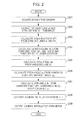
- Fig. 2 is a flowchart showing the operation of the calibration apparatus 100.
- Fig. 3 is an explanatory view showing how the vehicle is arranged when the acquirer 101 of the calibration apparatus 100 acquires an image from the camera 110.
- a first straight line a and a second straight line b are substantially perpendicular to a movement flat surface 300.
- the first straight line a and the second straight line b are two substantially perpendicular linearly-extending lines which are drawn on, for example, two cylindrical solids standing substantially perpendicularly to the movement flat surface 300 or a flat plate standing substantially perpendicularly to the movement flat surface 300.
- the first straight line a and the second straight line b are desired to be located such that a photographed camera image includes both of the straight lines.
- a movement flat surface here refers to a flat surface on which a vehicle moves and may be a surface angled with respect to a horizontal plane.
- the acquirer 101 acquires a photographed image of the first straight line a and the second straight line b from the camera 110 installed at a vehicle 301 which is arranged at a location shown in Fig. 3 (step S201).
- Fig. 4 is an explanatory view showing the image acquired by the acquirer 101 in step S201.
- a straight line a1 in Fig. 4 corresponds to the first straight line a in Fig. 3
- a straight line b1 corresponds to the second straight line b in Fig. 3 .
- the image acquired by the acquirer 101 is input to the extractor 102.
- the extractor 102 extracts the straight line a1 and the straight line b1 from the input image through image processing, such as comparing luminance at pixels of the image (step S202).
- the straight line a1 and the straight line b1 extracted in step S202 are input to the calculator 103.
- the calculator 103 calculates camera installation parameters with respect to a movement flat surface from the straight line a1 and the straight line b1 extracted by the extractor 102 and a point set as a vanishing point at a given location.
- the calculator 103 calculates, as a vanishing point VP1, an intersection of an extended line of the straight line a1 extracted by the extractor 102 and an extended line of the straight line b1 (step S203).
- the calculator 103 calculates, as a vanishing line VL, a line passing through the vanishing point VP1 calculated in step S203 and a vanishing point VP2 which is set at a given location different from that of the vanishing point VP1 (step S204).
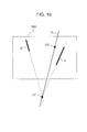
- Fig. 5 shows an example of the positional relation among the vanishing point VP1, the vanishing point VP2, and the vanishing line VL.
- the vanishing point VP2 is present within an image 500 in Fig. 5 , the vanishing point VP2 may be present at any location as long as the location is in an image space.
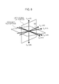
- a camera coordinate system is defined so as to have a Z c axis along an optical axis of the camera, a Y c axis along a direction perpendicular to the Z c axis and extending upward from the camera, and an X c axis along a direction perpendicular to the Z c axis and the Y c axis, as shown in Fig. 6A .
- a roll angle, a pitch angle, and a yaw angle are defined as a rotation angle about the Z c axis, a rotation angle about the X c axis, and a rotation angle about the Y c axis, respectively.
- a world coordinate system is defined so as to have a Y w axis perpendicular to the movement flat surface and an X w axis and a Z w axis perpendicular to the Y w axis and perpendicular to each other, as shown in Fig. 6B .
- Expression 1 indicates that coordinates obtained by rotating the coordinates (X w ,Y w ,Z w ) in the world coordinate system in the order of yaw angle, pitch angle, and roll angle are the coordinates (X c ,Y c ,Z c ) in the camera coordinate system.
- the relation between the coordinates (X c ,Y c ,Z c ) in the camera coordinate system and the coordinates (X w ,Y w ,Z w ) in the world coordinate system is defined by rotation angles as camera installation parameters and a rotation order as an order in which the camera installation parameters are applied. For this reason, even if the relation between the coordinates (X c ,Y c ,Z c ) in the camera coordinate system and the coordinates (X w ,Y w ,Z w ) in the world coordinate system is the same, for example, rotation angles for the rotation order of yaw angle, pitch angle, and roll angle and rotation angles for the rotation order of yaw angle, roll angle, and pitch angle do not necessarily coincide with each other.
- a coordinate system in an image space is defined so as to have an origin at an upper left corner of an image 600, an X i axis along a rightward direction, and a Y i axis along a downward direction, as shown in Fig. 6C .
- the calculator 103 calculates, as a roll angle ⁇ 1 , an angle which a straight line parallel to the X i axis forms with the vanishing line VL calculated in step S204 (step S205).
- the calculator 103 calculates a pitch angle ⁇ 1 , using a focal length of the camera 110, coordinates of the vanishing point VP2 set at the given location, and the roll angle ⁇ 1 calculated in step S205 (step S206).
- the calculator 103 calculates a yaw angle ⁇ 1 , using the focal length of the camera 110, coordinates of the vanishing point VP1 calculated in step S203, the vanishing line VL calculated in step S204, and the pitch angle ⁇ 1 calculated in step S206 (step S207).
- Fig. 7A is a view showing the relation between the world coordinate system and the camera coordinate system, between which coordinate conversion is performed on the basis of camera installation parameters calculated using parallel lines parallel to a movement flat surface, as illustrated in Japanese Unexamined Patent Application Publication No. 2008-11174 or "Camera Calibration by Vanishing Lines for 3D Computer Vision" (to be described later).
- Camera installation parameters calculated using two sets of parallel lines parallel to a movement flat surface that are illustrated in Japanese Unexamined Patent Application Publication No. 2008-11174 or "Camera Calibration by Vanishing Lines for 3D Computer Vision" (to be described later) are camera installation parameters for converting coordinates in the world coordinate system having the Z w axis parallel to one set of parallel lines of the two sets of parallel lines, the Y w axis perpendicular to a surface (the movement flat surface) parallel to the two sets of parallel lines, and the X w axis perpendicular to the Z w axis and the Y w axis to coordinates in the camera coordinate system.
- camera installation parameters calculated by the processes from step S204 to step S207 are camera installation parameters for converting coordinates in a world coordinate system shown in Fig. 7B to coordinates in the camera coordinate system.
- the camera installation parameters calculated by the processes from step S204 to step S207 are camera installation parameters for converting coordinates in a world coordinate system having a Z w' axis perpendicular to the movement flat surface and an X w' axis and a Y w' axis perpendicular to the Z w' axis and perpendicular to each other to coordinates in the camera coordinate system.
- Setting the other vanishing point is equivalent to setting a flat surface (orthogonal flat surface) substantially perpendicular to a movement flat surface for calculating the vanishing point. That is, setting the other vanishing point leads to identifying the X w' axis and the Y w' axis for the movement flat surface.
- the world coordinate system represented by the X w' axis, the Y w' axis, and the Z w' axis will be referred to as an orthogonal world coordinate system hereinafter.
- the method by Ling-Ling Wang et al. calculates a roll angle from a vanishing line connecting two vanishing points, calculates a pitch angle from the vanishing points and the roll angle, and calculates a yaw angle from the vanishing points, the vanishing line, and the pitch angle. That is, if two vanishing points are not calculated (for example, if only one vanishing point is calculated), neither a roll angle, a pitch angle, nor a yaw angle can be calculated. To calculate camera installation parameters, presence of two sets of parallel lines on a movement flat surface is necessary.
- the calculator 103 converts the camera installation parameters for converting coordinates in the orthogonal world coordinate system as shown in Fig. 7B to coordinates in the camera coordinate system to camera installation parameters for converting coordinates in the world coordinate system as shown in Fig. 7A to coordinates in the camera coordinate system (step S208).
- Camera installation parameters with respect to the movement flat surface are camera installation parameters for converting coordinates in the world coordinate system as shown in Fig. 7A to coordinates in the camera coordinate system.
- To calculate camera installation parameters for converting coordinates in the world coordinate system as shown in Fig. 7A to coordinates in the camera coordinate system from camera installation parameters for converting coordinates in the orthogonal world coordinate system as shown in Fig. 7B to coordinates in the camera coordinate system camera installation parameters for converting coordinates in the world coordinate system as shown in Fig. 7A to coordinates in the orthogonal world coordinate system as shown in Fig. 7B may be used.
- the camera installation parameters for converting the coordinates (X w ,Y w ,Z w ) in the world coordinate system to the coordinates (X c ,Y c ,Z c ) in the camera coordinate system are calculated by Expression 2 and Expression 3.
- a relational expression between the coordinates (X w ,Y w ,Z w ) in the world coordinate system and the coordinates (X c ,Y c ,Z c ) in the camera coordinate system is derived as Expression 5.
- camera installation parameters to be applied in the rotation order of yaw angle, pitch angle, and roll angle cannot be obtained.
- a process is performed of integrating six rotation matrices on the right side of Expression 5 into three rotation matrices for a yaw angle, a pitch angle, and a roll angle.
- a fourth matrix from the left on the right side is a unit matrix and can be removed.
- Expression 5 is transformed into Expression 6:
- x c y c z c cos ⁇ 1 sin ⁇ 1 0 - sin ⁇ 1 cos ⁇ 1 0 0 0 1 ⁇ 1 0 0 0 cos ⁇ 1 sin ⁇ 1 0 - sin ⁇ 1 cos ⁇ 1 ⁇ cos ⁇ 1 0 - sin ⁇ 1 0 1 0 sin ⁇ 1 0 cos ⁇ 1 1 0 0 0 cos ⁇ / 2 sin ⁇ / 2 0 - sin ⁇ / 2 cos ⁇ / 2 ⁇ cos ⁇ ⁇ 0 - sin ⁇ ⁇ 0 1 0 sin ⁇ ⁇ 0 cos ⁇ ⁇ x y w z w
- Rotation matrices for a pitch angle are integrated.
- the rotation matrices for a pitch angle can be expressed using the sum of angles, as shown in Expression 7, by multiplying the rotation matrices for a pitch angle.
- 1 0 0 0 cos ⁇ sin ⁇ 0 - sin ⁇ cos ⁇ ⁇ 1 0 0 0 cos ⁇ sin ⁇ 0 - sin ⁇ cos ⁇ 1 0 0 0 cos ⁇ + ⁇ sin ⁇ + ⁇ 0 - sin ⁇ + ⁇ cos ⁇ + ⁇
- the rotation matrices for a pitch angle are second and fourth ones from the left on the right side of Expression 6. For this reason, a process is performed of converting first to third matrices from the left on the right side of Expression 6, in which the rotation order for camera installation parameters is yaw angle, pitch angle, and roll angle, such that the rotation order for camera installation parameters is pitch angle, yaw angle, and roll angle, and making the rotation matrices for a pitch angle adjacent to each other.
- the calculator 103 performs a process of converting first to third matrices from the left on the right side of Expression 11, in which the rotation order for camera installation parameters is pitch angle, yaw angle, and roll angle, such that the rotation order for camera installation parameters is yaw angle, pitch angle, and roll angle. That is, the camera installation parameters are converted to camera installation parameters to be applied in the original rotation order.
- the yaw angle ⁇ 3 , the pitch angle ⁇ 3 , and the roll angle ⁇ 3 after the change of the rotation order for camera installation parameters can be calculated by solving the relational expression below (Expression 13): cos ⁇ 3 ⁇ cos ⁇ 3 + sin ⁇ 3 ⁇ sin ⁇ 3 ⁇ sin ⁇ 3 cos ⁇ 3 ⁇ sin ⁇ 3 - sin ⁇ 3 ⁇ cos ⁇ 3 + cos ⁇ 3 ⁇ sin ⁇ 3 ⁇ sin ⁇ 3 - cos ⁇ 3 ⁇ sin ⁇ 3 + sin ⁇ 3 ⁇ sin ⁇ 3 ⁇ cos ⁇ 3 cos ⁇ 3 sin ⁇ 3 sin ⁇ 3 + sin ⁇ 3 ⁇ sin ⁇ 3 ⁇ sin ⁇ 3 ⁇ sin ⁇ 3 + sin ⁇ 3 ⁇ sin ⁇ 3 ⁇ cos ⁇ 3 sin ⁇ 3 + sin ⁇ 3 ⁇ sin ⁇ 3 ⁇ cos ⁇ 3 sin ⁇ 3 + sin ⁇ 3 ⁇ sin ⁇ 3 ⁇ cos ⁇ 3
- Rotation matrices for a yaw angle are integrated.
- the product of matrices can be expressed using the sum of angles, like the case of a pitch angle. Since the rotation matrices for a yaw angle are third and fourth ones from the left on the right side in Expression 12, the rotation matrices are multiplied without change.
- the calculator 103 outputs the pitch angle ⁇ 3 and the roll angle ⁇ 3 of the calculated parameters as camera installation parameters with respect to the movement flat surface (step S209). Assuming that the vehicle is installed horizontal to the movement flat surface, the camera installation parameters output by the calculator 103 can be adopted as a pitch angle and a roll angle of camera installation parameters with respect to the vehicle. Since the calculated yaw angle ⁇ 3 + ⁇ includes ⁇ that is determined by an arbitrarily set point and is an angle which the X w axis forms with the X w' axis or an angle which the Z w axis forms with the Y w' axis, the yaw angle cannot be adopted as a yaw angle of the camera installation parameters with respect to the vehicle.
- a yaw angle which is a camera installation parameter with respect to a movement direction of the vehicle may be obtained on the basis of two images photographed before and after movement of the vehicle.
- Fig. 9 is an image which is photographed by the camera 110 after the vehicle moves straight forward a fixed distance after photographing of the image shown in Fig. 4 .
- a straight line a2 in Fig. 9 corresponds to the first straight line a in Fig. 3 while a straight line b2 corresponds to the second straight line b in Fig. 3 .
- Fig. 10 is an image obtained by superimposing the image shown in Fig. 9 on the image shown in Fig. 4 .
- the points P1 to P4 need not be intersections of straight lines and the movement flat surface as long as the distances from the points P1 to P4 to the movement flat surface are all equal.
- the distances from lower end points of the straight lines a1, a2, b1, and b2 to the movement flat surface and the lengths of the straight lines are all equal, upper end points detected through image processing or the like or the lower end points may be adopted as the points P1 to P4.
- a yaw angle ⁇ 4 as a camera installation parameter with respect to the movement direction of the vehicle is calculated from the calculated intersection VP', the pitch angle ⁇ 3 and the roll angle ⁇ 3 as camera installation parameters with respect to the movement flat surface calculated by the calculator 103, center coordinates C of the image, and a focal length f of the camera by the equation below Expression 16:
- ⁇ 4 tan - 1 ⁇ dist VC ⁇ sin ⁇ 3 + tan - 1 ⁇ VC x / - VC y ⁇ cos ⁇ 3 / f
- VC x represents the difference between an X coordinate of the intersection VP' and an X coordinate of the image center coordinates C
- VCy represents the difference between a Y coordinate of the intersection VP' and a Y coordinate of the image center coordinates C.
- the camera installation parameter calculation method described here is merely exemplary, and camera installation parameters may be calculated using a different method.
- the camera installation parameter conversion method described here is merely exemplary, and camera installation parameters may be converted using a different method.
- the extractor 102 extracts a linearly-extending line substantially perpendicular to the movement flat surface.
- Two points which are to be connected to form a straight line substantially perpendicular to the movement flat surface may be extracted, the two points may be connected to form a straight line, and the straight line may be adopted as a linearly-extending line substantially perpendicular to the movement flat surface.
- the present embodiment has been described in the context of a camera installed at a movable body.
- the present disclosure is not limited to a case where a camera is installed at a movable body, and a camera may be fixed on a wall or a ceiling, like a security camera.
- the calibration apparatus may be implemented by dedicated hardware or by recording a program for implementing the function of the calibration apparatus on a computer-readable storage medium and causing a computer to load and execute the recorded program.
- the storage medium may be mounted in the camera 110, and the camera 110 may be configured as a camera having a calibration function.
- the distance between the straight line a and the straight line b is desired to be such that a photographed image includes the straight lines a and b.
- the distance may be 50 cm or 10 m.
- a surface on which a movable body moves is a flat surface
- two lines extracted by the extractor 102 are straight lines
- a movement flat surface and the two straight lines are substantially perpendicular to each other.
- a flat surface, a straight line, and perpendicularity having strict accuracy are not requirements in the present disclosure.
- the accuracy of calculating camera installation parameters depends on the accuracy of a flat surface, a straight line, and perpendicularity.
- the accuracy of a flat surface, a straight line, and perpendicularity is desired to achieve the accuracy of calculating installation parameters required by an application or the like.
- a surface for movement may be a bumpy surface or a curved surface
- two lines extracted by the extractor 102 may be curved lines or broken lines
- a movement flat surface and two straight lines may not be strictly perpendicular to each other.
- the calibration apparatus can calculate camera installation parameters with respect to a flat surface without use of two sets of parallel lines on the flat surface, with respect to which camera installation parameters are to be obtained but with use of two linearly-extending lines substantially perpendicular to the flat surface.
- Fig. 11 is a block diagram showing the configuration of the calibration apparatus according to the second embodiment of the present disclosure.
- a calibration apparatus 1100 includes an acquirer 1101 which acquires an image, including one linearly-extending line substantially perpendicular to a movement flat surface (for example, a road surface), photographed by a camera 110 installed at a vehicle, an extractor 1102 which extracts the linearly-extending line substantially perpendicular to the movement flat surface from the image acquired by the acquirer 1101 through image processing, and a calculator 1103 which calculates camera installation parameters with respect to the movement flat surface from the linearly-extending line extracted by the extractor 1102.
- an acquirer 1101 which acquires an image, including one linearly-extending line substantially perpendicular to a movement flat surface (for example, a road surface), photographed by a camera 110 installed at a vehicle
- an extractor 1102 which extracts the linearly-extending line substantially perpendicular to the movement flat surface from the image acquired by the acquirer 1101 through image processing
- a calculator 1103 which calculates camera installation parameters with respect to the movement flat surface from the linearly-extending line extracted by the extractor 1102.
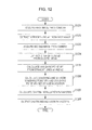
- Fig. 12 is a flowchart showing the operation of the calibration apparatus 1100.
- Fig. 13 is an explanatory view showing how the acquirer 1101 of the calibration apparatus 1100 acquires an image from the camera 110.
- a straight line a is a linearly-extending line substantially perpendicular to a movement flat surface 1300.
- the straight line a is one substantially perpendicular linearly-extending line which is drawn on, for example, a cylindrical solid standing substantially perpendicularly to the movement flat surface 1300 or a flat surface standing substantially perpendicularly to the movement flat surface 1300.
- a movement flat surface here refers to a smooth surface on which a vehicle moves and may be a surface angled with respect to a horizontal plane.
- the acquirer 1101 acquires a photographed image of the straight line a (a first image) from the camera 110 installed at a vehicle 1301 which is arranged at a first image acquisition location shown in Fig. 13 (step S1201).
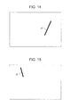
- Fig. 15 is an explanatory view showing the first image acquired by the acquirer 1101 in step S1201.
- a straight line a1 in Fig. 14 corresponds to the straight line a in Fig. 13 .
- the image acquired by the acquirer 1101 is input to the extractor 1102.
- the extractor 1102 extracts the straight line a1 from the input image through image processing, such as comparing luminance at pixels of the image (step S1202).
- the acquirer 1101 acquires a photographed image of the straight line a (a second image) from the camera 110 installed at a vehicle 1302 which is arranged at a second image acquisition location after vehicle movement shown in Fig. 13 (step S1203).
- Fig. 15 is an explanatory view showing the second image acquired by the acquirer 1101 in step S1203.
- a straight line a2 in Fig. 15 corresponds to the straight line a in Fig. 13 .
- the image acquired by the acquirer 1101 is input to the extractor 1102.
- the extractor 1102 performs the same processing as in step S1202 and extracts the straight line a2 from the input image (step S1204).
- the straight line a1 extracted in step S1202 and the straight line a2 extracted in step S1204 are input to the calculator 1103.
- the calculator 1103 calculates camera installation parameters with respect to the movement flat surface from the straight lines a1 and a2 extracted by the extractor 1102 and a vanishing point set at a given location.
- the calculator 1103 calculates, as a vanishing point VP1, an intersection of a straight line as an extended line of the straight line a1 extracted by the extractor 1102 and a straight line as an extended line of the straight line a2 (step S1205).
- the calculator 1103 calculates, as a vanishing line VL, a straight line passing through the vanishing point VP1 calculated in step S1205 and a vanishing point VP2 set at a given location different from that of the vanishing point VP1 (step S1206).
- Fig. 16 shows an example of the positional relation among the vanishing point VP1, the vanishing point VP2, and the vanishing line VL.
- the vanishing point VP2 is present within an image 1600 but may be present at any location as long as the location is in an image space.
- the calculator 1103 calculates camera installation parameters with respect to the movement flat surface using coordinates of the vanishing point VP1, the vanishing line VL, and a focal length of the camera 110 (step S1207) and outputs a calculation result (step S1208).
- a yaw angle which is a camera installation parameter with respect to a movement direction of the vehicle may be simultaneously obtained by causing the vehicle to move straight forward.
- An intersection VP' of a straight line, connecting an intersection of the straight line a1 and the movement flat surface and an intersection of the straight line a2 and the movement flat surface, and a straight line, connecting an upper end point of the straight line a1 and an upper end point of the straight line a2, is calculated.
- straight lines used to calculate the intersection VP' need not be a straight line, connecting the intersection of the straight line a1 and the movement flat surface and the intersection of the straight line a2 and the movement flat surface, and a straight line, connecting the upper end point of the straight line a1 and the upper end point of the straight line a2.
- the straight lines may be each a straight line connecting points equidistant from the movement flat surface in a real space.
- the yaw angle as the camera installation parameter with respect to the movement direction of the vehicle is calculated from the calculated intersection VP', a pitch angle and a roll angle as camera installation parameters with respect to the movement flat surface calculated by the calculator 1103, center coordinates of the image, and the focal length.
- the extractor 1102 extracts a linearly-extending line substantially perpendicular to the movement flat surface.
- Two points which are to be connected to form a straight line substantially perpendicular to the movement flat surface may be extracted, the two points may be connected to form a straight line, and the straight line may be adopted as a linearly-extending line substantially perpendicular to the movement flat surface.
- the same straight line a is photographed at the first image acquisition location before the movement and at the second image acquisition location after the movement.
- Different linearly-extending lines substantially perpendicular to the movement flat surface may be acquired at the first image acquisition location before the movement and at the second image acquisition location after the movement.
- the distance between the first image acquisition location and the second image acquisition location is desired to be such that the first and second images include the straight line a.
- the distance may be 50 cm or 10 m.
- the calibration apparatus shown in Fig. 11 may be incorporated in a camera, and the camera may be configured as a camera having a calibration function.
- the calibration apparatus can calculate camera installation parameters with respect to the movement flat surface using a vanishing point calculated from the two straight lines.
Landscapes
- Engineering & Computer Science (AREA)
- Physics & Mathematics (AREA)
- General Physics & Mathematics (AREA)
- Theoretical Computer Science (AREA)
- Computer Vision & Pattern Recognition (AREA)
- Multimedia (AREA)
- Length Measuring Devices By Optical Means (AREA)
- Studio Devices (AREA)
- Image Analysis (AREA)
- Closed-Circuit Television Systems (AREA)
- Mechanical Engineering (AREA)
Abstract
Description
- The present disclosure relates to calibration involving calculating a camera installation parameter on the basis of an image photographed by a camera.
- A technique for measuring the distance between a vehicle and an object in front of or behind the vehicle using a camera installed at the vehicle to issue a warning to a driver has been prevalent in recent years. To accurately measure the distance between the vehicle and the object, it is desirable to accurately calculate an installation location and an installation angle of the camera with respect to the vehicle (perform calibration).
- Common calibration techniques for obtaining an installation angle of a camera with respect to a vehicle include a technique utilizing a point (vanishing point) where parallel straight lines in a real space intersect in an image space.
- The calibration technique utilizing a vanishing point calculates a camera installation angle from at least two vanishing points, a vanishing point (depth vanishing point) calculated from parallel lines parallel to a traveling direction of the vehicle and a vanishing point calculated from any other parallel lines.
- A camera installation angle will be referred to as a camera installation parameter hereinafter.
- Calibration techniques for calculating a camera installation parameter utilizing a vanishing point include a technique for extracting two sets of parallel lines in a real space from a photographed image of a road marking, graphic feature quantities of which are stored in advance, to calculate two vanishing points from the extracted two sets of parallel lines (Japanese Unexamined Patent Application Publication No.
2008-11174 - To calculate a camera installation parameter with respect to a flat surface by the technique disclosed in Japanese Unexamined Patent Application Publication No.
2008-11174 - One non-limiting and exemplary embodiment provides a calibration apparatus, a calibration method, a camera having a calibration function, and a program capable of calculating a camera installation parameter with respect to a flat surface without use of two sets of parallel lines on the flat surface, with respect to which the camera installation parameter is to be obtained.
- In one general aspect, the techniques disclosed here feature a calibration apparatus for calculating a camera installation parameter with respect to a flat surface, the calibration apparatus including an acquirer which acquires a first image of one linearly-extending line substantially perpendicular to a movement flat surface that is photographed at a first time and a second image of the one linearly-extending line substantially perpendicular to the movement flat surface that is photographed at a second time after movement of a movable body, an extractor which extracts the one linearly-extending line from the first image and the one linearly-extending line from the second image through image processing, and a calculator which calculates a vanishing point from the one linearly-extending line extracted from the first image by the extractor and the one linearly-extending line extracted from the second image by the extractor and calculates a camera installation parameter with respect to the movement flat surface on a basis of coordinates of the vanishing point and given coordinates different from the coordinates of the vanishing point, a transmitter which transmit the camera installation parameter.
- The camera installation parameter with respect to the flat surface here is based on the definition of a camera coordinate system as having a Zc axis along an optical axis of a camera, a Yc axis along a direction perpendicular to the Zc axis and extending upward from the camera, and an Xc axis along a direction perpendicular to the Zc axis and the Yc axis and the definitions of a roll angle, a pitch angle, and a yaw angle which are camera installation parameters as a rotation angle about the Zc axis, a rotation angle about the Xc axis, and a rotation angle about the Yc axis and refers to the roll angle and the pitch angle at the time of rotation in the order of yaw angle, pitch angle, and roll angle.
- According to the present disclosure, it is possible to calculate a camera installation parameter with respect to a flat surface without use of two sets of parallel lines on the flat surface, with respect to which the camera installation parameter is to be obtained.
- It should be noted that general or specific embodiments may be implemented as a system, a method, an integrated circuit, a computer program, a storage medium, or any selective combination thereof.
- Additional benefits and advantages of the disclosed embodiments will become apparent from the specification and drawings. The benefits and/or advantages may be individually obtained by the various embodiments and features of the specification and drawings, which need not all be provided in order to obtain one or more of such benefits and/or advantages.
-
-
Fig. 1 is a block diagram showing an example of the configuration of a calibration apparatus according to a first embodiment of the present disclosure; -
Fig. 2 is a flowchart showing an example of the operation of the calibration apparatus according to the first embodiment of the present disclosure; -
Fig. 3 is an explanatory view showing how the calibration apparatus according to the first embodiment of the present disclosure acquires an image from a camera; -
Fig. 4 is an explanatory view showing an image photographed by the camera according to the first embodiment of the present disclosure; -
Fig. 5 is a conceptual view for explaining the operation of a calculator according to the first embodiment of the present disclosure; -
Figs. 6A to 6C are explanatory views for explaining definitions of coordinate systems according to the first embodiment of the present disclosure; -
Figs. 7A and 7B are explanatory views for explaining the relation between a world coordinate system and a camera coordinate system and the relation between an orthogonal world coordinate system and the camera coordinate system, according to the first embodiment of the present disclosure; -
Fig. 8 is an explanatory view for explaining the relation between the world coordinate system and the orthogonal world coordinate system, according to the first embodiment of the present disclosure; -
Fig. 9 is an explanatory view showing an image photographed by the camera after movement of a vehicle according to the first embodiment of the present disclosure; -
Fig. 10 is a conceptual view for explaining an estimated operation of a yaw angle associated with movement of the vehicle according to the first embodiment of the present disclosure; -
Fig. 11 is a block diagram showing an example of the configuration of a calibration apparatus according to a second embodiment of the present disclosure; -
Fig. 12 is a flowchart showing an example of the operation of the calibration apparatus according to the second embodiment of the present disclosure; -
Fig. 13 is an explanatory view showing how the calibration apparatus according to the second embodiment of the present disclosure acquires an image from a camera; -
Fig. 14 is an explanatory view showing a first image photographed by the camera according to the second embodiment of the present disclosure; -
Fig. 15 is an explanatory view showing a second image photographed by the camera according to the second embodiment of the present disclosure; and -
Fig. 16 is a conceptual view for explaining the operation of a calculator according to the second embodiment of the present disclosure. - Embodiments of the present disclosure will be described below with reference to the drawings. Note that although the embodiments of the present disclosure will be described in the context of a case where a camera is installed at a vehicle as a movable body, the present disclosure is not limited to a case where a camera is installed at a movable body.
- A calibration apparatus according to a first embodiment of the present disclosure will be described below.
-
Fig. 1 is a block diagram showing the configuration of acalibration apparatus 100 according to the first embodiment of the present disclosure. - In
Fig. 1 , anacquirer 101 acquires an image which is photographed by acamera 110 installed at a vehicle and includes two linearly-extending lines substantially perpendicular to a movement flat surface (for example, a road surface). Anextractor 102 extracts, through image processing, the two linearly-extending lines substantially perpendicular to the movement flat surface from the image acquired by theacquirer 101. Acalculator 103 calculates camera installation parameters with respect to the movement flat surface from the two linearly-extending lines extracted by theextractor 102. -
Fig. 2 is a flowchart showing the operation of thecalibration apparatus 100.Fig. 3 is an explanatory view showing how the vehicle is arranged when theacquirer 101 of thecalibration apparatus 100 acquires an image from thecamera 110. - In
Fig. 3 , a first straight line a and a second straight line b are substantially perpendicular to a movementflat surface 300. The first straight line a and the second straight line b are two substantially perpendicular linearly-extending lines which are drawn on, for example, two cylindrical solids standing substantially perpendicularly to the movementflat surface 300 or a flat plate standing substantially perpendicularly to the movementflat surface 300. - The first straight line a and the second straight line b are desired to be located such that a photographed camera image includes both of the straight lines. A movement flat surface here refers to a flat surface on which a vehicle moves and may be a surface angled with respect to a horizontal plane.
- The
acquirer 101 acquires a photographed image of the first straight line a and the second straight line b from thecamera 110 installed at avehicle 301 which is arranged at a location shown inFig. 3 (step S201). -
Fig. 4 is an explanatory view showing the image acquired by theacquirer 101 in step S201. A straight line a1 inFig. 4 corresponds to the first straight line a inFig. 3 , and a straight line b1 corresponds to the second straight line b inFig. 3 . - The image acquired by the
acquirer 101 is input to theextractor 102. Theextractor 102 extracts the straight line a1 and the straight line b1 from the input image through image processing, such as comparing luminance at pixels of the image (step S202). - The straight line a1 and the straight line b1 extracted in step S202 are input to the
calculator 103. - The
calculator 103 calculates camera installation parameters with respect to a movement flat surface from the straight line a1 and the straight line b1 extracted by theextractor 102 and a point set as a vanishing point at a given location. - The
calculator 103 calculates, as a vanishing point VP1, an intersection of an extended line of the straight line a1 extracted by theextractor 102 and an extended line of the straight line b1 (step S203). - The
calculator 103 calculates, as a vanishing line VL, a line passing through the vanishing point VP1 calculated in step S203 and a vanishing point VP2 which is set at a given location different from that of the vanishing point VP1 (step S204).Fig. 5 shows an example of the positional relation among the vanishing point VP1, the vanishing point VP2, and the vanishing line VL. Although the vanishing point VP2 is present within animage 500 inFig. 5 , the vanishing point VP2 may be present at any location as long as the location is in an image space. - In the present embodiment, a camera coordinate system is defined so as to have a Zc axis along an optical axis of the camera, a Yc axis along a direction perpendicular to the Zc axis and extending upward from the camera, and an Xc axis along a direction perpendicular to the Zc axis and the Yc axis, as shown in
Fig. 6A . Of camera installation parameters, a roll angle, a pitch angle, and a yaw angle are defined as a rotation angle about the Zc axis, a rotation angle about the Xc axis, and a rotation angle about the Yc axis, respectively. - A world coordinate system is defined so as to have a Yw axis perpendicular to the movement flat surface and an Xw axis and a Zw axis perpendicular to the Yw axis and perpendicular to each other, as shown in
Fig. 6B . - As described above, camera installation parameters in the present embodiment are only installation angles and are defined so as not to include installation locations. That is, origins of the camera coordinate system and the world coordinate system coincide with each other, and the relation between coordinates (Xc,Yc,Zc) in the camera coordinate system and coordinates (Xw,Yw,Zw) in the world coordinate system is represented by
Expression 1 including multiplication of three rotation matrices:
where ϕ represents a roll angle, φ represents a pitch angle, and θ represents a yaw angle. -
Expression 1 indicates that coordinates obtained by rotating the coordinates (Xw,Yw,Zw) in the world coordinate system in the order of yaw angle, pitch angle, and roll angle are the coordinates (Xc,Yc,Zc) in the camera coordinate system. - The relation between the coordinates (Xc,Yc,Zc) in the camera coordinate system and the coordinates (Xw,Yw,Zw) in the world coordinate system is defined by rotation angles as camera installation parameters and a rotation order as an order in which the camera installation parameters are applied. For this reason, even if the relation between the coordinates (Xc,Yc,Zc) in the camera coordinate system and the coordinates (Xw,Yw,Zw) in the world coordinate system is the same, for example, rotation angles for the rotation order of yaw angle, pitch angle, and roll angle and rotation angles for the rotation order of yaw angle, roll angle, and pitch angle do not necessarily coincide with each other.
- Thus, the same relation between the coordinates (Xc,Yc,Zc) in the camera coordinate system and the coordinates (Xw,Yw,Zw) in the world coordinate system can be expressed with different camera installation parameters by changing the rotation order.
- In a calibration method utilizing a vanishing point described in the present disclosure, Japanese Unexamined Patent Application Publication No.
2008-11174 Expression 1 are calculated. - A coordinate system in an image space is defined so as to have an origin at an upper left corner of an
image 600, an Xi axis along a rightward direction, and a Yi axis along a downward direction, as shown inFig. 6C . - The
calculator 103 calculates, as a roll angle ϕ1, an angle which a straight line parallel to the Xi axis forms with the vanishing line VL calculated in step S204 (step S205). Thecalculator 103 calculates a pitch angle φ1, using a focal length of thecamera 110, coordinates of the vanishing point VP2 set at the given location, and the roll angle ϕ1 calculated in step S205 (step S206). Thecalculator 103 calculates a yaw angle θ1, using the focal length of thecamera 110, coordinates of the vanishing point VP1 calculated in step S203, the vanishing line VL calculated in step S204, and the pitch angle φ1 calculated in step S206 (step S207). - The relation among world coordinate systems and the camera coordinate system in the processes from step S204 to step S207 will be described.
-
Fig. 7A is a view showing the relation between the world coordinate system and the camera coordinate system, between which coordinate conversion is performed on the basis of camera installation parameters calculated using parallel lines parallel to a movement flat surface, as illustrated in Japanese Unexamined Patent Application Publication No.2008-11174 - Camera installation parameters calculated using two sets of parallel lines parallel to a movement flat surface that are illustrated in Japanese Unexamined Patent Application Publication No.
2008-11174 - In the present embodiment, parallel lines used to calculate camera installation parameters are substantially perpendicular to a movement flat surface. For this reason, camera installation parameters calculated by the processes from step S204 to step S207 are camera installation parameters for converting coordinates in a world coordinate system shown in
Fig. 7B to coordinates in the camera coordinate system. - That is, the camera installation parameters calculated by the processes from step S204 to step S207 are camera installation parameters for converting coordinates in a world coordinate system having a Zw' axis perpendicular to the movement flat surface and an Xw' axis and a Yw' axis perpendicular to the Zw' axis and perpendicular to each other to coordinates in the camera coordinate system.
- In the present embodiment, there is only one vanishing point that is calculated from two linearly-extending lines substantially perpendicular to a movement flat surface, and an arbitrarily set point is adopted as the other vanishing point. Setting the other vanishing point is equivalent to setting a flat surface (orthogonal flat surface) substantially perpendicular to a movement flat surface for calculating the vanishing point. That is, setting the other vanishing point leads to identifying the Xw' axis and the Yw' axis for the movement flat surface. The world coordinate system represented by the Xw' axis, the Yw' axis, and the Zw' axis will be referred to as an orthogonal world coordinate system hereinafter.
- Note that a method for calculating camera installation parameters from vanishing points and a vanishing line is described in detail in Ling-Ling Wang et al., "Camera Calibration by Vanishing Lines for 3D Computer Vision", IEEE TRANSACTIONS on Pattern Analysis and Machine_Intelligence, Vol. 13, No. 4, pp. 370-376, April 1991.
- The method by Ling-Ling Wang et al. calculates a roll angle from a vanishing line connecting two vanishing points, calculates a pitch angle from the vanishing points and the roll angle, and calculates a yaw angle from the vanishing points, the vanishing line, and the pitch angle. That is, if two vanishing points are not calculated (for example, if only one vanishing point is calculated), neither a roll angle, a pitch angle, nor a yaw angle can be calculated. To calculate camera installation parameters, presence of two sets of parallel lines on a movement flat surface is necessary.
- The
calculator 103 converts the camera installation parameters for converting coordinates in the orthogonal world coordinate system as shown inFig. 7B to coordinates in the camera coordinate system to camera installation parameters for converting coordinates in the world coordinate system as shown inFig. 7A to coordinates in the camera coordinate system (step S208). - Camera installation parameters with respect to the movement flat surface are camera installation parameters for converting coordinates in the world coordinate system as shown in
Fig. 7A to coordinates in the camera coordinate system. To calculate camera installation parameters for converting coordinates in the world coordinate system as shown inFig. 7A to coordinates in the camera coordinate system from camera installation parameters for converting coordinates in the orthogonal world coordinate system as shown inFig. 7B to coordinates in the camera coordinate system, camera installation parameters for converting coordinates in the world coordinate system as shown inFig. 7A to coordinates in the orthogonal world coordinate system as shown inFig. 7B may be used. - That is, the equivalence between converting coordinates in the world coordinate system as shown in
Fig. 7A to coordinates in the orthogonal world coordinate system as shown inFig. 7B and then converting the coordinates to coordinates in the camera coordinate system and converting coordinates in the world coordinate system as shown inFig. 7A to coordinates in the camera coordinate system is used. - Assuming that the camera installation parameters calculated in steps S204 to S207 are the roll angle ϕ1, the pitch angle φ1, and the yaw angle θ1, the relation between coordinates (Xw',Yw',Zw') in the orthogonal world coordinate system and the coordinates (Xc,Yc,Zc) in the camera coordinate system is represented by Expression 2:

- The relation between the orthogonal world coordinate system and the world coordinate system is as shown in
Fig. 8 . From this, the relation between the coordinates (Xw,Yw,Zw) in the world coordinate system and the coordinates (Xw',Yw',Zw') in the orthogonal world coordinate system is represented by Expression 3:
where Δθ represents the relation between the movement flat surface and the Xw' axis and Yw' axis that is determined by an arbitrarily set point, that is, an angle which the Xw axis forms with the Xw' axis or an angle which the Zw axis forms with the Yw' axis. - The camera installation parameters for converting the coordinates (Xw,Yw,Zw) in the world coordinate system to the coordinates (Xc,Yc,Zc) in the camera coordinate system are calculated by Expression 2 and Expression 3.
- Both sides of Expression 3 are left multiplied by rotation matrices in the order of yaw angle θ1, pitch angle φ1, and roll angle ϕ1 to obtain Expression 4:

- Since the right side of Expression 2 is equal to the left side of Expression 4, Expression 4 is transformed into Expression 5:

- A relational expression between the coordinates (Xw,Yw,Zw) in the world coordinate system and the coordinates (Xc,Yc,Zc) in the camera coordinate system is derived as Expression 5. However, camera installation parameters to be applied in the rotation order of yaw angle, pitch angle, and roll angle cannot be obtained. For this reason, a process is performed of integrating six rotation matrices on the right side of Expression 5 into three rotation matrices for a yaw angle, a pitch angle, and a roll angle.
- A fourth matrix from the left on the right side is a unit matrix and can be removed. Expression 5 is transformed into Expression 6:

- Rotation matrices for a pitch angle are integrated. The rotation matrices for a pitch angle can be expressed using the sum of angles, as shown in Expression 7, by multiplying the rotation matrices for a pitch angle.

- At this time, the rotation matrices for a pitch angle are second and fourth ones from the left on the right side of Expression 6. For this reason, a process is performed of converting first to third matrices from the left on the right side of Expression 6, in which the rotation order for camera installation parameters is yaw angle, pitch angle, and roll angle, such that the rotation order for camera installation parameters is pitch angle, yaw angle, and roll angle, and making the rotation matrices for a pitch angle adjacent to each other.
- The relation between coordinates in the camera coordinate system and coordinates in the world coordinate system when rotation order is pitch angle, yaw angle, and roll angle is represented by Expression 8:

where ϕ2 represents a roll angle after the conversion, θ2 represents a yaw angle after the conversion, and φ2 represents a pitch angle after the conversion. - Since the product of rotation matrices in Expression 6 and the product of rotation matrices in Expression 8 are equal, the roll angle ϕ2, the pitch angle φ2, and the yaw angle θ2 are calculated by solving the relational expression below Expression 9 indicating the products of rotation matrices and constants.

where C1 to C9 represent constants calculated by the relational expression below Expression 10:
- Since the rotation matrices for a pitch angle lie side by side, the rotation matrices can be multiplied. Expression 8 is transformed into Expression 11:

- The
calculator 103 performs a process of converting first to third matrices from the left on the right side of Expression 11, in which the rotation order for camera installation parameters is pitch angle, yaw angle, and roll angle, such that the rotation order for camera installation parameters is yaw angle, pitch angle, and roll angle. That is, the camera installation parameters are converted to camera installation parameters to be applied in the original rotation order. - The relation between coordinates in the world coordinate system and coordinates in the camera coordinate system when the rotation order is pitch angle, yaw angle, and roll angle is represented by Expression 12:

where ϕ3 represents a roll angle after the conversion, φ3 represents a pitch angle after the conversion, and θ3 represents a yaw angle after the conversion. - The yaw angle θ3, the pitch angle φ3, and the roll angle ϕ3 after the change of the rotation order for camera installation parameters can be calculated by solving the relational expression below (Expression 13):

where C'1 to C'9 represent constants calculated by the relational expression below Expression 14:
- Note that conversion has been performed in Expression 8 such that the rotation order of first to third matrices from the left on the right side is pitch angle, yaw angle, and roll angle. The present disclosure is not limited to the rotation order, and rotation for a pitch angle only needs to be the third.
- Rotation matrices for a yaw angle are integrated. In the case of a yaw angle, the product of matrices can be expressed using the sum of angles, like the case of a pitch angle. Since the rotation matrices for a yaw angle are third and fourth ones from the left on the right side in Expression 12, the rotation matrices are multiplied without change. The product is represented by Expression 15:

- In the above-described manner, a relational expression between the coordinates (Xw,Yw,Zw) in the world coordinate system and the coordinates (Xc,Yc,Zc) in the camera coordinate system which is expressed using the rotation order of yaw angle, pitch angle, and roll angle is derived.
- The
calculator 103 outputs the pitch angle φ3 and the roll angle ϕ3 of the calculated parameters as camera installation parameters with respect to the movement flat surface (step S209). Assuming that the vehicle is installed horizontal to the movement flat surface, the camera installation parameters output by thecalculator 103 can be adopted as a pitch angle and a roll angle of camera installation parameters with respect to the vehicle. Since the calculated yaw angle θ3+Δθ includes Δθ that is determined by an arbitrarily set point and is an angle which the Xw axis forms with the Xw' axis or an angle which the Zw axis forms with the Yw' axis, the yaw angle cannot be adopted as a yaw angle of the camera installation parameters with respect to the vehicle. - Note that, if the straight lines a and b are line segments or half lines, a yaw angle which is a camera installation parameter with respect to a movement direction of the vehicle may be obtained on the basis of two images photographed before and after movement of the vehicle.
Fig. 9 is an image which is photographed by thecamera 110 after the vehicle moves straight forward a fixed distance after photographing of the image shown inFig. 4 . A straight line a2 inFig. 9 corresponds to the first straight line a inFig. 3 while a straight line b2 corresponds to the second straight line b inFig. 3 . -
Fig. 10 is an image obtained by superimposing the image shown inFig. 9 on the image shown inFig. 4 . An intersection VP' of a straight line connecting a point P1, which is an intersection of the straight line a1 and the movement flat surface, and a point P2, which is an intersection of the straight line a2 and the movement flat surface, and a straight line connecting a point P3, which is an intersection of the straight line b1 and the movement flat surface, and a point P4, which is an intersection of the straight line b2 and the movement flat surface, is calculated. - Note that the points P1 to P4 need not be intersections of straight lines and the movement flat surface as long as the distances from the points P1 to P4 to the movement flat surface are all equal. For example, if the distances from lower end points of the straight lines a1, a2, b1, and b2 to the movement flat surface and the lengths of the straight lines are all equal, upper end points detected through image processing or the like or the lower end points may be adopted as the points P1 to P4.
- A yaw angle θ4 as a camera installation parameter with respect to the movement direction of the vehicle is calculated from the calculated intersection VP', the pitch angle φ3 and the roll angle ϕ3 as camera installation parameters with respect to the movement flat surface calculated by the
calculator 103, center coordinates C of the image, and a focal length f of the camera by the equation below Expression 16:
where VCx represents the difference between an X coordinate of the intersection VP' and an X coordinate of the image center coordinates C, and VCy represents the difference between a Y coordinate of the intersection VP' and a Y coordinate of the image center coordinates C. - The camera installation parameter calculation method described here is merely exemplary, and camera installation parameters may be calculated using a different method.
- The camera installation parameter conversion method described here is merely exemplary, and camera installation parameters may be converted using a different method.
- In the present embodiment, the
extractor 102 extracts a linearly-extending line substantially perpendicular to the movement flat surface. Two points which are to be connected to form a straight line substantially perpendicular to the movement flat surface may be extracted, the two points may be connected to form a straight line, and the straight line may be adopted as a linearly-extending line substantially perpendicular to the movement flat surface. - The present embodiment has been described in the context of a camera installed at a movable body. The present disclosure, however, is not limited to a case where a camera is installed at a movable body, and a camera may be fixed on a wall or a ceiling, like a security camera.
- The calibration apparatus according to the first embodiment of the present disclosure may be implemented by dedicated hardware or by recording a program for implementing the function of the calibration apparatus on a computer-readable storage medium and causing a computer to load and execute the recorded program.
- The storage medium may be mounted in the
camera 110, and thecamera 110 may be configured as a camera having a calibration function. - The distance between the straight line a and the straight line b is desired to be such that a photographed image includes the straight lines a and b. For example, the distance may be 50 cm or 10 m.
- A surface on which a movable body moves is a flat surface, two lines extracted by the
extractor 102 are straight lines, and a movement flat surface and the two straight lines are substantially perpendicular to each other. A flat surface, a straight line, and perpendicularity having strict accuracy are not requirements in the present disclosure. The accuracy of calculating camera installation parameters depends on the accuracy of a flat surface, a straight line, and perpendicularity. The accuracy of a flat surface, a straight line, and perpendicularity is desired to achieve the accuracy of calculating installation parameters required by an application or the like. For example, a surface for movement may be a bumpy surface or a curved surface, two lines extracted by theextractor 102 may be curved lines or broken lines, and a movement flat surface and two straight lines may not be strictly perpendicular to each other. - As described above, the calibration apparatus according to the first embodiment of the present disclosure can calculate camera installation parameters with respect to a flat surface without use of two sets of parallel lines on the flat surface, with respect to which camera installation parameters are to be obtained but with use of two linearly-extending lines substantially perpendicular to the flat surface.
- A calibration apparatus according to a second embodiment of the present disclosure will be described below.
-
Fig. 11 is a block diagram showing the configuration of the calibration apparatus according to the second embodiment of the present disclosure. - In
Fig. 11 , acalibration apparatus 1100 includes anacquirer 1101 which acquires an image, including one linearly-extending line substantially perpendicular to a movement flat surface (for example, a road surface), photographed by acamera 110 installed at a vehicle, anextractor 1102 which extracts the linearly-extending line substantially perpendicular to the movement flat surface from the image acquired by theacquirer 1101 through image processing, and acalculator 1103 which calculates camera installation parameters with respect to the movement flat surface from the linearly-extending line extracted by theextractor 1102. -
Fig. 12 is a flowchart showing the operation of thecalibration apparatus 1100.Fig. 13 is an explanatory view showing how theacquirer 1101 of thecalibration apparatus 1100 acquires an image from thecamera 110. - In
Fig. 13 , a straight line a is a linearly-extending line substantially perpendicular to a movementflat surface 1300. The straight line a is one substantially perpendicular linearly-extending line which is drawn on, for example, a cylindrical solid standing substantially perpendicularly to the movementflat surface 1300 or a flat surface standing substantially perpendicularly to the movementflat surface 1300. A movement flat surface here refers to a smooth surface on which a vehicle moves and may be a surface angled with respect to a horizontal plane. - The
acquirer 1101 acquires a photographed image of the straight line a (a first image) from thecamera 110 installed at avehicle 1301 which is arranged at a first image acquisition location shown inFig. 13 (step S1201). -
Fig. 15 is an explanatory view showing the first image acquired by theacquirer 1101 in step S1201. A straight line a1 inFig. 14 corresponds to the straight line a inFig. 13 . - The image acquired by the
acquirer 1101 is input to theextractor 1102. Theextractor 1102 extracts the straight line a1 from the input image through image processing, such as comparing luminance at pixels of the image (step S1202). - The
acquirer 1101 acquires a photographed image of the straight line a (a second image) from thecamera 110 installed at avehicle 1302 which is arranged at a second image acquisition location after vehicle movement shown inFig. 13 (step S1203). -
Fig. 15 is an explanatory view showing the second image acquired by theacquirer 1101 in step S1203. A straight line a2 inFig. 15 corresponds to the straight line a inFig. 13 . - The image acquired by the
acquirer 1101 is input to theextractor 1102. Theextractor 1102 performs the same processing as in step S1202 and extracts the straight line a2 from the input image (step S1204). - The straight line a1 extracted in step S1202 and the straight line a2 extracted in step S1204 are input to the
calculator 1103. - The
calculator 1103 calculates camera installation parameters with respect to the movement flat surface from the straight lines a1 and a2 extracted by theextractor 1102 and a vanishing point set at a given location. - The
calculator 1103 calculates, as a vanishing point VP1, an intersection of a straight line as an extended line of the straight line a1 extracted by theextractor 1102 and a straight line as an extended line of the straight line a2 (step S1205). - The
calculator 1103 calculates, as a vanishing line VL, a straight line passing through the vanishing point VP1 calculated in step S1205 and a vanishing point VP2 set at a given location different from that of the vanishing point VP1 (step S1206). -
Fig. 16 shows an example of the positional relation among the vanishing point VP1, the vanishing point VP2, and the vanishing line VL. InFig. 16 , the vanishing point VP2 is present within animage 1600 but may be present at any location as long as the location is in an image space. - As described in the first embodiment, the
calculator 1103 calculates camera installation parameters with respect to the movement flat surface using coordinates of the vanishing point VP1, the vanishing line VL, and a focal length of the camera 110 (step S1207) and outputs a calculation result (step S1208). - Note that, if the straight line a is a line segment, a yaw angle which is a camera installation parameter with respect to a movement direction of the vehicle may be simultaneously obtained by causing the vehicle to move straight forward. An intersection VP' of a straight line, connecting an intersection of the straight line a1 and the movement flat surface and an intersection of the straight line a2 and the movement flat surface, and a straight line, connecting an upper end point of the straight line a1 and an upper end point of the straight line a2, is calculated. Note that straight lines used to calculate the intersection VP' need not be a straight line, connecting the intersection of the straight line a1 and the movement flat surface and the intersection of the straight line a2 and the movement flat surface, and a straight line, connecting the upper end point of the straight line a1 and the upper end point of the straight line a2. The straight lines may be each a straight line connecting points equidistant from the movement flat surface in a real space.
- The yaw angle as the camera installation parameter with respect to the movement direction of the vehicle is calculated from the calculated intersection VP', a pitch angle and a roll angle as camera installation parameters with respect to the movement flat surface calculated by the
calculator 1103, center coordinates of the image, and the focal length. - In the present embodiment, the
extractor 1102 extracts a linearly-extending line substantially perpendicular to the movement flat surface. Two points which are to be connected to form a straight line substantially perpendicular to the movement flat surface may be extracted, the two points may be connected to form a straight line, and the straight line may be adopted as a linearly-extending line substantially perpendicular to the movement flat surface. - In the present embodiment, the same straight line a is photographed at the first image acquisition location before the movement and at the second image acquisition location after the movement. Different linearly-extending lines substantially perpendicular to the movement flat surface may be acquired at the first image acquisition location before the movement and at the second image acquisition location after the movement.
- The distance between the first image acquisition location and the second image acquisition location is desired to be such that the first and second images include the straight line a. For example, the distance may be 50 cm or 10 m.
- The calibration apparatus shown in
Fig. 11 may be incorporated in a camera, and the camera may be configured as a camera having a calibration function. - As described above, since a linearly-extending line substantially perpendicular to the movement flat surface on an image photographed before vehicle movement and a linearly-extending line substantially perpendicular to the movement flat surface on the image photographed after the vehicle movement are both substantially perpendicular to the movement flat surface in a real space, the calibration apparatus according to the second embodiment of the present disclosure can calculate camera installation parameters with respect to the movement flat surface using a vanishing point calculated from the two straight lines.
Claims (4)
- A calibration apparatus comprising:an acquirer which acquires a first image of one linearly-extending line substantially perpendicular to a movement flat surface that is photographed at a first time and a second image of the one linearly-extending line substantially perpendicular to the movement flat surface that is photographed at a second time after movement of a movable body;an extractor which extracts the one linearly-extending line from the first image and the one linearly-extending line from the second image through image processing;a calculator which calculates a vanishing point from the one linearly-extending line extracted from the first image by the extractor and the one linearly-extending line extracted from the second image by the extractor and calculates a camera installation parameter with respect to the movement flat surface on a basis of coordinates of the vanishing point and given coordinates different from the coordinates of the vanishing point; anda transmitter which transmit the camera installation parameter.
- The calibration apparatus according to Claim 1, further comprises a camera which acquires the image.
- A calibration method comprising:acquiring a first image of one linearly-extending line substantially perpendicular to a movement flat surface that is photographed at a first time;extracting a first straight line corresponding to the one linearly-extending line from the first image through image processing;acquiring a second image of the one linearly-extending line substantially perpendicular to the movement flat surface that is photographed at a second time after movement of a movable body after the first time;extracting a second straight line corresponding to the one linearly-extending line from the second image through image processing;calculating a vanishing point from the first straight line and the second straight line;calculating a camera installation parameter with respect to the movement flat surface on a basis of coordinates of the vanishing point and given coordinates different from the coordinates of the vanishing point; andtransmitting the camera installation parameter.
- A calibration program for causing a computer to execute:a process of acquiring a first image of one linearly-extending line substantially perpendicular to a movement flat surface that is photographed at a first time;a process of extracting a first straight line corresponding to the one linearly-extending line from the first image through image processing;a process of acquiring a second image of the one linearly-extending line substantially perpendicular to the movement flat surface that is photographed at a second time after movement of a movable body after the first time;a process of extracting a second straight line corresponding to the one linearly-extending line from the second image through image processing;a process of calculating a vanishing point from the first straight line and the second straight line;a process of calculating a camera installation parameter with respect to the movement flat surface on a basis of coordinates of the vanishing point and given coordinates different from the coordinates of the vanishing point; anda process of transmitting the camera installation parameter.
Applications Claiming Priority (1)
| Application Number | Priority Date | Filing Date | Title |
|---|---|---|---|
| JP2014075915A JP6326624B2 (en) | 2014-04-02 | 2014-04-02 | CALIBRATION DEVICE, CALIBRATION METHOD, CAMERA HAVING CALIBRATION FUNCTION, AND PROGRAM |
Publications (2)
| Publication Number | Publication Date |
|---|---|
| EP2927870A1 true EP2927870A1 (en) | 2015-10-07 |
| EP2927870B1 EP2927870B1 (en) | 2019-05-08 |
Family
ID=52784927
Family Applications (1)
| Application Number | Title | Priority Date | Filing Date |
|---|---|---|---|
| EP15160026.9A Active EP2927870B1 (en) | 2014-04-02 | 2015-03-20 | Calibration apparatus, calibration method, and calibration program |
Country Status (3)
| Country | Link |
|---|---|
| US (1) | US10032274B2 (en) |
| EP (1) | EP2927870B1 (en) |
| JP (1) | JP6326624B2 (en) |
Cited By (4)
| Publication number | Priority date | Publication date | Assignee | Title |
|---|---|---|---|---|
| CN105046691A (en) * | 2015-06-26 | 2015-11-11 | 浙江大学 | Method for camera self-calibration based on orthogonal vanishing points |
| CN106454120A (en) * | 2016-11-18 | 2017-02-22 | 上海传英信息技术有限公司 | Mobile terminal having photo taking function and photographing method |
| EP3389015A1 (en) * | 2017-04-13 | 2018-10-17 | Continental Automotive GmbH | Roll angle calibration method and roll angle calibration device |
| CN112288821A (en) * | 2019-07-25 | 2021-01-29 | 上海高德威智能交通系统有限公司 | Method and device for calibrating external parameters of camera |
Families Citing this family (14)
| Publication number | Priority date | Publication date | Assignee | Title |
|---|---|---|---|---|
| JP2017112566A (en) * | 2015-12-18 | 2017-06-22 | 株式会社デンソー | Parameter identification device |
| EP3435333B1 (en) * | 2017-07-26 | 2020-01-29 | Aptiv Technologies Limited | Method of determining the roll angle of a vehicle mounted camera |
| WO2020014683A1 (en) * | 2018-07-13 | 2020-01-16 | Kache.AI | Systems and methods for autonomous object detection and vehicle following |
| TWI720447B (en) * | 2019-03-28 | 2021-03-01 | 財團法人工業技術研究院 | Image positioning method and system thereof |
| CN111223150A (en) * | 2020-01-15 | 2020-06-02 | 电子科技大学 | Vehicle-mounted camera external parameter calibration method based on double vanishing points |
| KR20220026422A (en) | 2020-08-25 | 2022-03-04 | 삼성전자주식회사 | Apparatus and method for calibrating camera |
| WO2023014246A1 (en) * | 2021-08-06 | 2023-02-09 | Общество с ограниченной ответственностью "ЭвоКарго" | Method of calibrating extrinsic video camera parameters |
| CN113706630B (en) * | 2021-08-26 | 2024-02-06 | 西安电子科技大学 | Method for calibrating pitch angle of camera based on group of horizontal parallel lines |
| CN115760585B (en) * | 2021-09-03 | 2026-04-24 | 小米科技(武汉)有限公司 | Image correction methods, devices, storage media and electronic devices |
| CN114663529B (en) * | 2022-03-22 | 2023-08-01 | 阿波罗智能技术(北京)有限公司 | External parameter determining method and device, electronic equipment and storage medium |
| CN114937088B (en) * | 2022-04-12 | 2024-11-08 | 浙江大华技术股份有限公司 | Camera equipment calibration method, training method, image processing method and device |
| CN117095063A (en) * | 2022-05-11 | 2023-11-21 | 富士通株式会社 | Camera parameter determination device and method |
| JP7850619B2 (en) * | 2022-07-21 | 2026-04-23 | 京セラ株式会社 | State estimation device, state estimation method, and state estimation program |
| JPWO2024195180A1 (en) * | 2023-03-23 | 2024-09-26 |
Citations (4)
| Publication number | Priority date | Publication date | Assignee | Title |
|---|---|---|---|---|
| JP2008011174A (en) | 2006-06-29 | 2008-01-17 | Hitachi Ltd | Car camera calibration device, program, and car navigation system |
| US20120081512A1 (en) * | 2009-06-18 | 2012-04-05 | Fujitsu Limited | Image processing device and image processing method |
| WO2012145818A1 (en) * | 2011-04-25 | 2012-11-01 | Magna International Inc. | Method and system for dynamically calibrating vehicular cameras |
| US20130070108A1 (en) * | 2010-03-26 | 2013-03-21 | Maarten Aerts | Method and arrangement for multi-camera calibration |
Family Cites Families (6)
| Publication number | Priority date | Publication date | Assignee | Title |
|---|---|---|---|---|
| JP4573977B2 (en) * | 1999-09-22 | 2010-11-04 | 富士重工業株式会社 | Distance correction device for monitoring system and vanishing point correction device for monitoring system |
| JP4860431B2 (en) * | 2006-10-26 | 2012-01-25 | 三菱電機株式会社 | Image generation device |
| GB2465792A (en) * | 2008-11-28 | 2010-06-02 | Sony Corp | Illumination Direction Estimation using Reference Object |
| JP5552892B2 (en) * | 2010-05-13 | 2014-07-16 | 富士通株式会社 | Image processing apparatus and image processing program |
| US9092695B1 (en) * | 2013-03-13 | 2015-07-28 | Google Inc. | High-accuracy real-time road sign detection from images |
| JP6201148B2 (en) * | 2013-12-20 | 2017-09-27 | パナソニックIpマネジメント株式会社 | CALIBRATION APPARATUS, CALIBRATION METHOD, MOBILE BODY CAMERA HAVING CALIBRATION FUNCTION, AND PROGRAM |
-
2014
- 2014-04-02 JP JP2014075915A patent/JP6326624B2/en not_active Expired - Fee Related
-
2015
- 2015-03-20 EP EP15160026.9A patent/EP2927870B1/en active Active
- 2015-03-27 US US14/671,682 patent/US10032274B2/en active Active
Patent Citations (4)
| Publication number | Priority date | Publication date | Assignee | Title |
|---|---|---|---|---|
| JP2008011174A (en) | 2006-06-29 | 2008-01-17 | Hitachi Ltd | Car camera calibration device, program, and car navigation system |
| US20120081512A1 (en) * | 2009-06-18 | 2012-04-05 | Fujitsu Limited | Image processing device and image processing method |
| US20130070108A1 (en) * | 2010-03-26 | 2013-03-21 | Maarten Aerts | Method and arrangement for multi-camera calibration |
| WO2012145818A1 (en) * | 2011-04-25 | 2012-11-01 | Magna International Inc. | Method and system for dynamically calibrating vehicular cameras |
Non-Patent Citations (1)
| Title |
|---|
| LING-LING WANG ET AL.: "Camera Calibration by Vanishing Lines for 3D Computer Vision", IEEE TRANSACTIONS ON PATTERN ANALYSIS AND MACHINE_INTELLIGENCE, vol. 13, no. 4, April 1991 (1991-04-01), pages 370 - 376, XP000214964, DOI: doi:10.1109/34.88572 |
Cited By (6)
| Publication number | Priority date | Publication date | Assignee | Title |
|---|---|---|---|---|
| CN105046691A (en) * | 2015-06-26 | 2015-11-11 | 浙江大学 | Method for camera self-calibration based on orthogonal vanishing points |
| CN105046691B (en) * | 2015-06-26 | 2018-04-10 | 浙江大学 | A kind of Camera Self-Calibration method based on orthogonal end point |
| CN106454120A (en) * | 2016-11-18 | 2017-02-22 | 上海传英信息技术有限公司 | Mobile terminal having photo taking function and photographing method |
| EP3389015A1 (en) * | 2017-04-13 | 2018-10-17 | Continental Automotive GmbH | Roll angle calibration method and roll angle calibration device |
| CN112288821A (en) * | 2019-07-25 | 2021-01-29 | 上海高德威智能交通系统有限公司 | Method and device for calibrating external parameters of camera |
| CN112288821B (en) * | 2019-07-25 | 2024-04-23 | 上海高德威智能交通系统有限公司 | A method and device for calibrating camera extrinsic parameters |
Also Published As
| Publication number | Publication date |
|---|---|
| US10032274B2 (en) | 2018-07-24 |
| JP2015198374A (en) | 2015-11-09 |
| JP6326624B2 (en) | 2018-05-23 |
| US20150287197A1 (en) | 2015-10-08 |
| EP2927870B1 (en) | 2019-05-08 |
Similar Documents
| Publication | Publication Date | Title |
|---|---|---|
| EP2927870B1 (en) | Calibration apparatus, calibration method, and calibration program | |
| US10424081B2 (en) | Method and apparatus for calibrating a camera system of a motor vehicle | |
| EP3057063B1 (en) | Object detection device and vehicle using same | |
| EP3407294A1 (en) | Information processing method, device, and terminal | |
| US11482013B2 (en) | Object tracking method, object tracking apparatus, vehicle having the same, and computer-program product | |
| US9122948B1 (en) | System and method for evaluating the perception system of an autonomous vehicle | |
| US9336595B2 (en) | Calibration device, method for implementing calibration, and camera for movable body and storage medium with calibration function | |
| CN107305632B (en) | Monocular computer vision technology-based target object distance measuring method and system | |
| CN102203552B (en) | Parallax calculation method and parallax calculation device | |
| US9415723B2 (en) | Image integration unit and image integration method | |
| US9898669B2 (en) | Traveling road surface detection device and traveling road surface detection method | |
| EP2824425A1 (en) | Moving-object position/attitude estimation apparatus and method for estimating position/attitude of moving object | |
| US11783507B2 (en) | Camera calibration apparatus and operating method | |
| US9715632B2 (en) | Intersection recognizing apparatus and computer-readable storage medium | |
| US10187630B2 (en) | Egomotion estimation system and method | |
| US10740908B2 (en) | Moving object | |
| CN104463163A (en) | Apparatus and method for extracting feature point for recognizing obstacle using laser scanner | |
| WO2016146559A1 (en) | Method for determining a position of an object in a three-dimensional world coordinate system, computer program product, camera system and motor vehicle | |
| KR20190134303A (en) | Apparatus and method for image recognition | |
| Zaarane et al. | Vehicle to vehicle distance measurement for self-driving systems | |
| JP2013168057A (en) | Road boundary determination device and road boundary determination method | |
| CN104574273A (en) | Point cloud registration system and method | |
| CN103523021B (en) | Lane detection confidence level method of calculating and perform its computer device | |
| JP2012159470A (en) | Vehicle image recognition device | |
| KR102100047B1 (en) | Method for position recognition of vehicle using lane-end-point detection algorithm and method for evaluating performance of the same |
Legal Events
| Date | Code | Title | Description |
|---|---|---|---|
| PUAI | Public reference made under article 153(3) epc to a published international application that has entered the european phase |
Free format text: ORIGINAL CODE: 0009012 |
|
| AK | Designated contracting states |
Kind code of ref document: A1 Designated state(s): AL AT BE BG CH CY CZ DE DK EE ES FI FR GB GR HR HU IE IS IT LI LT LU LV MC MK MT NL NO PL PT RO RS SE SI SK SM TR |
|
| AX | Request for extension of the european patent |
Extension state: BA ME |
|
| 17P | Request for examination filed |
Effective date: 20160407 |
|
| RBV | Designated contracting states (corrected) |
Designated state(s): AL AT BE BG CH CY CZ DE DK EE ES FI FR GB GR HR HU IE IS IT LI LT LU LV MC MK MT NL NO PL PT RO RS SE SI SK SM TR |
|
| STAA | Information on the status of an ep patent application or granted ep patent |
Free format text: STATUS: EXAMINATION IS IN PROGRESS |
|
| 17Q | First examination report despatched |
Effective date: 20170201 |
|
| REG | Reference to a national code |
Ref country code: DE Ref legal event code: R079 Ref document number: 602015029642 Country of ref document: DE Free format text: PREVIOUS MAIN CLASS: G06T0007000000 Ipc: G06K0009000000 |
|
| GRAP | Despatch of communication of intention to grant a patent |
Free format text: ORIGINAL CODE: EPIDOSNIGR1 |
|
| STAA | Information on the status of an ep patent application or granted ep patent |
Free format text: STATUS: GRANT OF PATENT IS INTENDED |
|
| RIC1 | Information provided on ipc code assigned before grant |
Ipc: G08G 1/16 20060101ALI20181003BHEP Ipc: G06T 7/536 20170101ALI20181003BHEP Ipc: G06T 7/80 20170101ALI20181003BHEP Ipc: G06T 7/00 20060101ALI20181003BHEP Ipc: G06T 7/579 20170101ALI20181003BHEP Ipc: G06K 9/00 20060101AFI20181003BHEP Ipc: B60R 1/00 20060101ALI20181003BHEP |
|
| INTG | Intention to grant announced |
Effective date: 20181029 |
|
| GRAS | Grant fee paid |
Free format text: ORIGINAL CODE: EPIDOSNIGR3 |
|
| RIC1 | Information provided on ipc code assigned before grant |
Ipc: G08G 1/16 20060101ALI20181003BHEP Ipc: G06T 7/536 20170101ALI20181003BHEP Ipc: G06T 7/579 20170101ALI20181003BHEP Ipc: B60R 1/00 20060101ALI20181003BHEP Ipc: G06K 9/00 20060101AFI20181003BHEP Ipc: G06T 7/00 20170101ALI20181003BHEP Ipc: G06T 7/80 20170101ALI20181003BHEP |
|
| GRAA | (expected) grant |
Free format text: ORIGINAL CODE: 0009210 |
|
| STAA | Information on the status of an ep patent application or granted ep patent |
Free format text: STATUS: THE PATENT HAS BEEN GRANTED |
|
| AK | Designated contracting states |
Kind code of ref document: B1 Designated state(s): AL AT BE BG CH CY CZ DE DK EE ES FI FR GB GR HR HU IE IS IT LI LT LU LV MC MK MT NL NO PL PT RO RS SE SI SK SM TR |
|
| REG | Reference to a national code |
Ref country code: GB Ref legal event code: FG4D |
|
| REG | Reference to a national code |
Ref country code: CH Ref legal event code: EP Ref country code: AT Ref legal event code: REF Ref document number: 1131347 Country of ref document: AT Kind code of ref document: T Effective date: 20190515 |
|
| REG | Reference to a national code |
Ref country code: DE Ref legal event code: R096 Ref document number: 602015029642 Country of ref document: DE |
|
| REG | Reference to a national code |
Ref country code: IE Ref legal event code: FG4D |
|
| REG | Reference to a national code |
Ref country code: NL Ref legal event code: MP Effective date: 20190508 |
|
| REG | Reference to a national code |
Ref country code: LT Ref legal event code: MG4D |
|
| PG25 | Lapsed in a contracting state [announced via postgrant information from national office to epo] |
Ref country code: LT Free format text: LAPSE BECAUSE OF FAILURE TO SUBMIT A TRANSLATION OF THE DESCRIPTION OR TO PAY THE FEE WITHIN THE PRESCRIBED TIME-LIMIT Effective date: 20190508 Ref country code: NL Free format text: LAPSE BECAUSE OF FAILURE TO SUBMIT A TRANSLATION OF THE DESCRIPTION OR TO PAY THE FEE WITHIN THE PRESCRIBED TIME-LIMIT Effective date: 20190508 Ref country code: HR Free format text: LAPSE BECAUSE OF FAILURE TO SUBMIT A TRANSLATION OF THE DESCRIPTION OR TO PAY THE FEE WITHIN THE PRESCRIBED TIME-LIMIT Effective date: 20190508 Ref country code: ES Free format text: LAPSE BECAUSE OF FAILURE TO SUBMIT A TRANSLATION OF THE DESCRIPTION OR TO PAY THE FEE WITHIN THE PRESCRIBED TIME-LIMIT Effective date: 20190508 Ref country code: PT Free format text: LAPSE BECAUSE OF FAILURE TO SUBMIT A TRANSLATION OF THE DESCRIPTION OR TO PAY THE FEE WITHIN THE PRESCRIBED TIME-LIMIT Effective date: 20190908 Ref country code: FI Free format text: LAPSE BECAUSE OF FAILURE TO SUBMIT A TRANSLATION OF THE DESCRIPTION OR TO PAY THE FEE WITHIN THE PRESCRIBED TIME-LIMIT Effective date: 20190508 Ref country code: SE Free format text: LAPSE BECAUSE OF FAILURE TO SUBMIT A TRANSLATION OF THE DESCRIPTION OR TO PAY THE FEE WITHIN THE PRESCRIBED TIME-LIMIT Effective date: 20190508 Ref country code: AL Free format text: LAPSE BECAUSE OF FAILURE TO SUBMIT A TRANSLATION OF THE DESCRIPTION OR TO PAY THE FEE WITHIN THE PRESCRIBED TIME-LIMIT Effective date: 20190508 Ref country code: NO Free format text: LAPSE BECAUSE OF FAILURE TO SUBMIT A TRANSLATION OF THE DESCRIPTION OR TO PAY THE FEE WITHIN THE PRESCRIBED TIME-LIMIT Effective date: 20190808 |
|
| PG25 | Lapsed in a contracting state [announced via postgrant information from national office to epo] |
Ref country code: BG Free format text: LAPSE BECAUSE OF FAILURE TO SUBMIT A TRANSLATION OF THE DESCRIPTION OR TO PAY THE FEE WITHIN THE PRESCRIBED TIME-LIMIT Effective date: 20190808 Ref country code: GR Free format text: LAPSE BECAUSE OF FAILURE TO SUBMIT A TRANSLATION OF THE DESCRIPTION OR TO PAY THE FEE WITHIN THE PRESCRIBED TIME-LIMIT Effective date: 20190809 Ref country code: LV Free format text: LAPSE BECAUSE OF FAILURE TO SUBMIT A TRANSLATION OF THE DESCRIPTION OR TO PAY THE FEE WITHIN THE PRESCRIBED TIME-LIMIT Effective date: 20190508 Ref country code: RS Free format text: LAPSE BECAUSE OF FAILURE TO SUBMIT A TRANSLATION OF THE DESCRIPTION OR TO PAY THE FEE WITHIN THE PRESCRIBED TIME-LIMIT Effective date: 20190508 |
|
| REG | Reference to a national code |
Ref country code: AT Ref legal event code: MK05 Ref document number: 1131347 Country of ref document: AT Kind code of ref document: T Effective date: 20190508 |
|
| PG25 | Lapsed in a contracting state [announced via postgrant information from national office to epo] |
Ref country code: EE Free format text: LAPSE BECAUSE OF FAILURE TO SUBMIT A TRANSLATION OF THE DESCRIPTION OR TO PAY THE FEE WITHIN THE PRESCRIBED TIME-LIMIT Effective date: 20190508 Ref country code: AT Free format text: LAPSE BECAUSE OF FAILURE TO SUBMIT A TRANSLATION OF THE DESCRIPTION OR TO PAY THE FEE WITHIN THE PRESCRIBED TIME-LIMIT Effective date: 20190508 Ref country code: RO Free format text: LAPSE BECAUSE OF FAILURE TO SUBMIT A TRANSLATION OF THE DESCRIPTION OR TO PAY THE FEE WITHIN THE PRESCRIBED TIME-LIMIT Effective date: 20190508 Ref country code: CZ Free format text: LAPSE BECAUSE OF FAILURE TO SUBMIT A TRANSLATION OF THE DESCRIPTION OR TO PAY THE FEE WITHIN THE PRESCRIBED TIME-LIMIT Effective date: 20190508 Ref country code: SK Free format text: LAPSE BECAUSE OF FAILURE TO SUBMIT A TRANSLATION OF THE DESCRIPTION OR TO PAY THE FEE WITHIN THE PRESCRIBED TIME-LIMIT Effective date: 20190508 Ref country code: DK Free format text: LAPSE BECAUSE OF FAILURE TO SUBMIT A TRANSLATION OF THE DESCRIPTION OR TO PAY THE FEE WITHIN THE PRESCRIBED TIME-LIMIT Effective date: 20190508 |
|
| REG | Reference to a national code |
Ref country code: DE Ref legal event code: R097 Ref document number: 602015029642 Country of ref document: DE |
|
| PG25 | Lapsed in a contracting state [announced via postgrant information from national office to epo] |
Ref country code: SM Free format text: LAPSE BECAUSE OF FAILURE TO SUBMIT A TRANSLATION OF THE DESCRIPTION OR TO PAY THE FEE WITHIN THE PRESCRIBED TIME-LIMIT Effective date: 20190508 Ref country code: IT Free format text: LAPSE BECAUSE OF FAILURE TO SUBMIT A TRANSLATION OF THE DESCRIPTION OR TO PAY THE FEE WITHIN THE PRESCRIBED TIME-LIMIT Effective date: 20190508 |
|
| PLBE | No opposition filed within time limit |
Free format text: ORIGINAL CODE: 0009261 |
|
| STAA | Information on the status of an ep patent application or granted ep patent |
Free format text: STATUS: NO OPPOSITION FILED WITHIN TIME LIMIT |
|
| PG25 | Lapsed in a contracting state [announced via postgrant information from national office to epo] |
Ref country code: TR Free format text: LAPSE BECAUSE OF FAILURE TO SUBMIT A TRANSLATION OF THE DESCRIPTION OR TO PAY THE FEE WITHIN THE PRESCRIBED TIME-LIMIT Effective date: 20190508 |
|
| 26N | No opposition filed |
Effective date: 20200211 |
|
| PG25 | Lapsed in a contracting state [announced via postgrant information from national office to epo] |
Ref country code: PL Free format text: LAPSE BECAUSE OF FAILURE TO SUBMIT A TRANSLATION OF THE DESCRIPTION OR TO PAY THE FEE WITHIN THE PRESCRIBED TIME-LIMIT Effective date: 20190508 |
|
| PG25 | Lapsed in a contracting state [announced via postgrant information from national office to epo] |
Ref country code: SI Free format text: LAPSE BECAUSE OF FAILURE TO SUBMIT A TRANSLATION OF THE DESCRIPTION OR TO PAY THE FEE WITHIN THE PRESCRIBED TIME-LIMIT Effective date: 20190508 |
|
| PG25 | Lapsed in a contracting state [announced via postgrant information from national office to epo] |
Ref country code: MC Free format text: LAPSE BECAUSE OF FAILURE TO SUBMIT A TRANSLATION OF THE DESCRIPTION OR TO PAY THE FEE WITHIN THE PRESCRIBED TIME-LIMIT Effective date: 20190508 |
|
| REG | Reference to a national code |
Ref country code: CH Ref legal event code: PL |
|
| REG | Reference to a national code |
Ref country code: BE Ref legal event code: MM Effective date: 20200331 |
|
| PG25 | Lapsed in a contracting state [announced via postgrant information from national office to epo] |
Ref country code: LU Free format text: LAPSE BECAUSE OF NON-PAYMENT OF DUE FEES Effective date: 20200320 |
|
| PG25 | Lapsed in a contracting state [announced via postgrant information from national office to epo] |
Ref country code: LI Free format text: LAPSE BECAUSE OF NON-PAYMENT OF DUE FEES Effective date: 20200331 Ref country code: IE Free format text: LAPSE BECAUSE OF NON-PAYMENT OF DUE FEES Effective date: 20200320 Ref country code: FR Free format text: LAPSE BECAUSE OF NON-PAYMENT OF DUE FEES Effective date: 20200331 Ref country code: CH Free format text: LAPSE BECAUSE OF NON-PAYMENT OF DUE FEES Effective date: 20200331 |
|
| PG25 | Lapsed in a contracting state [announced via postgrant information from national office to epo] |
Ref country code: BE Free format text: LAPSE BECAUSE OF NON-PAYMENT OF DUE FEES Effective date: 20200331 |
|
| GBPC | Gb: european patent ceased through non-payment of renewal fee |
Effective date: 20200320 |
|
| PG25 | Lapsed in a contracting state [announced via postgrant information from national office to epo] |
Ref country code: GB Free format text: LAPSE BECAUSE OF NON-PAYMENT OF DUE FEES Effective date: 20200320 |
|
| REG | Reference to a national code |
Ref country code: DE Ref legal event code: R079 Ref document number: 602015029642 Country of ref document: DE Free format text: PREVIOUS MAIN CLASS: G06K0009000000 Ipc: G06V0010000000 |
|
| PG25 | Lapsed in a contracting state [announced via postgrant information from national office to epo] |
Ref country code: MT Free format text: LAPSE BECAUSE OF FAILURE TO SUBMIT A TRANSLATION OF THE DESCRIPTION OR TO PAY THE FEE WITHIN THE PRESCRIBED TIME-LIMIT Effective date: 20190508 Ref country code: CY Free format text: LAPSE BECAUSE OF FAILURE TO SUBMIT A TRANSLATION OF THE DESCRIPTION OR TO PAY THE FEE WITHIN THE PRESCRIBED TIME-LIMIT Effective date: 20190508 |
|
| PG25 | Lapsed in a contracting state [announced via postgrant information from national office to epo] |
Ref country code: MK Free format text: LAPSE BECAUSE OF FAILURE TO SUBMIT A TRANSLATION OF THE DESCRIPTION OR TO PAY THE FEE WITHIN THE PRESCRIBED TIME-LIMIT Effective date: 20190508 Ref country code: IS Free format text: LAPSE BECAUSE OF FAILURE TO SUBMIT A TRANSLATION OF THE DESCRIPTION OR TO PAY THE FEE WITHIN THE PRESCRIBED TIME-LIMIT Effective date: 20190908 |
|
| REG | Reference to a national code |
Ref country code: DE Ref legal event code: R081 Ref document number: 602015029642 Country of ref document: DE Owner name: PANASONIC AUTOMOTIVE SYSTEMS CO., LTD., YOKOHA, JP Free format text: FORMER OWNER: PANASONIC INTELLECTUAL PROPERTY MANAGEMENT CO., LTD., OSAKA, JP |
|
| PGFP | Annual fee paid to national office [announced via postgrant information from national office to epo] |
Ref country code: DE Payment date: 20260319 Year of fee payment: 12 |