EP2927863A1 - Vehicle-mounted image processing device - Google Patents
Vehicle-mounted image processing device Download PDFInfo
- Publication number
- EP2927863A1 EP2927863A1 EP13859419.7A EP13859419A EP2927863A1 EP 2927863 A1 EP2927863 A1 EP 2927863A1 EP 13859419 A EP13859419 A EP 13859419A EP 2927863 A1 EP2927863 A1 EP 2927863A1
- Authority
- EP
- European Patent Office
- Prior art keywords
- parking line
- line recognition
- image
- vehicle
- bird
- Prior art date
- Legal status (The legal status is an assumption and is not a legal conclusion. Google has not performed a legal analysis and makes no representation as to the accuracy of the status listed.)
- Granted
Links
Images










Classifications
-
- B—PERFORMING OPERATIONS; TRANSPORTING
- B60—VEHICLES IN GENERAL
- B60R—VEHICLES, VEHICLE FITTINGS, OR VEHICLE PARTS, NOT OTHERWISE PROVIDED FOR
- B60R1/00—Optical viewing arrangements; Real-time viewing arrangements for drivers or passengers using optical image capturing systems, e.g. cameras or video systems specially adapted for use in or on vehicles
- B60R1/20—Real-time viewing arrangements for drivers or passengers using optical image capturing systems, e.g. cameras or video systems specially adapted for use in or on vehicles
- B60R1/22—Real-time viewing arrangements for drivers or passengers using optical image capturing systems, e.g. cameras or video systems specially adapted for use in or on vehicles for viewing an area outside the vehicle, e.g. the exterior of the vehicle
- B60R1/23—Real-time viewing arrangements for drivers or passengers using optical image capturing systems, e.g. cameras or video systems specially adapted for use in or on vehicles for viewing an area outside the vehicle, e.g. the exterior of the vehicle with a predetermined field of view
- B60R1/27—Real-time viewing arrangements for drivers or passengers using optical image capturing systems, e.g. cameras or video systems specially adapted for use in or on vehicles for viewing an area outside the vehicle, e.g. the exterior of the vehicle with a predetermined field of view providing all-round vision, e.g. using omnidirectional cameras
-
- B—PERFORMING OPERATIONS; TRANSPORTING
- B60—VEHICLES IN GENERAL
- B60R—VEHICLES, VEHICLE FITTINGS, OR VEHICLE PARTS, NOT OTHERWISE PROVIDED FOR
- B60R1/00—Optical viewing arrangements; Real-time viewing arrangements for drivers or passengers using optical image capturing systems, e.g. cameras or video systems specially adapted for use in or on vehicles
- B60R1/20—Real-time viewing arrangements for drivers or passengers using optical image capturing systems, e.g. cameras or video systems specially adapted for use in or on vehicles
- B60R1/22—Real-time viewing arrangements for drivers or passengers using optical image capturing systems, e.g. cameras or video systems specially adapted for use in or on vehicles for viewing an area outside the vehicle, e.g. the exterior of the vehicle
- B60R1/28—Real-time viewing arrangements for drivers or passengers using optical image capturing systems, e.g. cameras or video systems specially adapted for use in or on vehicles for viewing an area outside the vehicle, e.g. the exterior of the vehicle with an adjustable field of view
-
- G—PHYSICS
- G06—COMPUTING OR CALCULATING; COUNTING
- G06V—IMAGE OR VIDEO RECOGNITION OR UNDERSTANDING
- G06V20/00—Scenes; Scene-specific elements
- G06V20/50—Context or environment of the image
- G06V20/56—Context or environment of the image exterior to a vehicle by using sensors mounted on the vehicle
- G06V20/58—Recognition of moving objects or obstacles, e.g. vehicles or pedestrians; Recognition of traffic objects, e.g. traffic signs, traffic lights or roads
-
- G—PHYSICS
- G06—COMPUTING OR CALCULATING; COUNTING
- G06V—IMAGE OR VIDEO RECOGNITION OR UNDERSTANDING
- G06V20/00—Scenes; Scene-specific elements
- G06V20/50—Context or environment of the image
- G06V20/56—Context or environment of the image exterior to a vehicle by using sensors mounted on the vehicle
- G06V20/58—Recognition of moving objects or obstacles, e.g. vehicles or pedestrians; Recognition of traffic objects, e.g. traffic signs, traffic lights or roads
- G06V20/586—Recognition of moving objects or obstacles, e.g. vehicles or pedestrians; Recognition of traffic objects, e.g. traffic signs, traffic lights or roads of parking space
-
- G—PHYSICS
- G06—COMPUTING OR CALCULATING; COUNTING
- G06V—IMAGE OR VIDEO RECOGNITION OR UNDERSTANDING
- G06V40/00—Recognition of biometric, human-related or animal-related patterns in image or video data
- G06V40/10—Human or animal bodies, e.g. vehicle occupants or pedestrians; Body parts, e.g. hands
-
- G—PHYSICS
- G08—SIGNALLING
- G08G—TRAFFIC CONTROL SYSTEMS
- G08G1/00—Traffic control systems for road vehicles
- G08G1/16—Anti-collision systems
- G08G1/166—Anti-collision systems for active traffic, e.g. moving vehicles, pedestrians, bikes
-
- G—PHYSICS
- G08—SIGNALLING
- G08G—TRAFFIC CONTROL SYSTEMS
- G08G1/00—Traffic control systems for road vehicles
- G08G1/16—Anti-collision systems
- G08G1/167—Driving aids for lane monitoring, lane changing, e.g. blind spot detection
-
- G—PHYSICS
- G08—SIGNALLING
- G08G—TRAFFIC CONTROL SYSTEMS
- G08G1/00—Traffic control systems for road vehicles
- G08G1/16—Anti-collision systems
- G08G1/168—Driving aids for parking, e.g. acoustic or visual feedback on parking space
-
- H—ELECTRICITY
- H04—ELECTRIC COMMUNICATION TECHNIQUE
- H04N—PICTORIAL COMMUNICATION, e.g. TELEVISION
- H04N7/00—Television systems
- H04N7/18—Closed-circuit television [CCTV] systems, i.e. systems in which the video signal is not broadcast
Definitions
- the present invention relates to a vehicle-mounted image processing device that recognizes the outside of a vehicle based on an image taken by a vehicle-mounted camera.
- Patent Literature 1 discloses a technique of taking an image of the surrounding of a vehicle as a whole using each of four cameras mounted on the vehicle on the front, rear, left and right, converting and combining these through-images to create a bird's eye view image, and recognizing a parking line based on the bird's eye view image.
- apparatuses to provide a user with a bird's eye view image provide both of a bird's eye view image and a through-image in the vehicle traveling direction. This is because while a bird's eye view image is suitable for a driver to recognize surroundings of the vehicle, a through-image is more suitable to understand a remote place and a three-dimensional object.
- a bird's eye view image of the images to be provided to a user has a narrow viewing field (about 2 m in the front of the vehicle) as compared with a through-image that is not subjected to processing, and so such an image is not suitable to recognize a remote place.
- a narrow viewing field about 2 m in the front of the vehicle
- a through-image has a wider viewing field than that of a bird's eye view image, and can recognize a remote place, and so typically image processing is often performed based on a through-image to recognize a lane, for example.
- a bird's eye view image is easily processed compared with a through-image not subjected to conversion, and for example, it is easier to perform calculation, such as departure prediction from a white line, based on a bird's eye view image. In this way, precision for recognition may be improved in some applications by using a bird's eye view image.
- the present invention aims to provide a vehicle-mounted image processing device capable of recognizing the outside of a vehicle based on an image taken by a vehicle-mounted camera more precisely.
- a vehicle-mounted image processing device of the present invention includes: an image acquisition unit that acquires through-images taken by cameras disposed on front, rear and sides of a vehicle; a bird's eye view image generation unit that converts the acquired through images to generate a bird's eye view image; a parking line recognition unit that performs parking line recognition processing to recognize a parking line based on at least one of the through-images and the bird's eye view image.
- the parking line recognition unit performs first parking line recognition processing based on the bird's eye view image to recognize a parking line in a predetermined range of the bird's eye view image, and second parking line recognition processing based on the through-images to recognize a parking line in an area that is far away from the predetermined range of the bird's eye view image.
- a vehicle-mounted image processing device of the present invention recognizes a parking line in a predetermined range based on a bird's eye view image, and recognizes a parking line in an area far away from the predetermined range of the bird's eye view image based on a through-image, and so can perform image processing based on an appropriate image depending on the situation and can recognize the parking line more precisely.
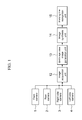
- FIG. 1 is a block diagram to describe the configuration of a vehicle-mounted image processing device of the present embodiment
- FIG. 2 illustrates an image to describe the configuration of a bird's eye view image generation unit.
- the vehicle-mounted image processing device is implemented by hardware and software in a camera device mounted on a vehicle 10.
- the vehicle-mounted image processing device includes an image acquisition unit 12, a bird's eye view image generation unit 13, an image synthesis unit 14, and a parking line recognition unit 15 as its internal functions.
- the image acquisition unit 12 acquires through-images taken by a front camera 1, a rear camera 2, a right side camera 3, and a left side camera 4 that are attached on the front, the rear, the right side and the left side, respectively, of the vehicle 10.
- the bird's eye view image generation unit 13 converts the through-images acquired by the image acquisition unit 12 to generate a bird's eye view image 25 having a point of view that is shifted to the above of the vehicle 10.
- the bird's eye view image 25 is generated using a well-known technique.
- the image synthesis unit 14 synthesizes at least one of the through-images and a bird's eye view image.
- the parking line recognition unit 15 as an outside recognition unit performs processing to recognize the outside parking line WL from the synthesized image synthesized by the image synthesis unit 14 and based on at least one of the through-images and the bird's eye view image.
- images of the state where the vehicle 10 enters the parking line WL from the front are taken by the cameras 1 to 4.
- the parking line WL is defined with marking lines WL1 to WL3 using white or yellow paint for partitioning of the area for one vehicle.
- the parking line WL includes marking lines WL1 and WL2 for partitioning of both sides in the vehicle width direction, and a marking line WL3 for partitioning in the vehicle front-rear direction.
- Each through-image 21 to 24 shows the parking line WL located around the vehicle.
- the bird's eye view image 25 that is generated by converting the through-images 21 to 24 shows the marking lines WL1 and WL2 and the marking line WL3 on the front side of the vehicle that surround the vehicle 10.
- FIG. 3 is a flowchart to describe a method of synthesizing an image for recognition of the parking line
- FIG. 4 illustrates an image where a bird's eye view image and a rear camera image are synthesized
- FIG. 5 illustrates an image where a bird's eye view image and a front camera image are synthesized.
- the image synthesis unit 14 acquires shift position information on the vehicle 10 (Step S101).
- the shift position information is acquired from a controller to control a driving system of the vehicle 10 via a CAN, for example.
- the shift position information contains information on the position of a shift of the vehicle 10, for example, in the case of a manual transmission, the position of a shift lever, and in the case of an automatic transmission, the position of a selector lever.
- Step S102 determination is made based on the shift position information whether the position of reverse R is selected or not.
- a bird's eye view image 25 and a through-image 22 of the rear camera 2 are synthesized (Step S103).
- the bird's eye view image 25 and a through-image 21 of the front camera 1 are synthesized (Step S104). Note here that although one through-image and a bird's eye view image are synthesized in this example, a plurality of through-images and a bird's eye view image may be synthesized.
- FIG. 6 is a flowchart to describe an exemplary method for recognizing of the parking line
- FIG. 7 is a flowchart to describe a method for recognizing of the parking line based on a bird's eye view image
- FIG. 8 is a flowchart to describe a method for recognizing of the parking line based on a through-image
- the parking line recognition unit 15 firstly performs first parking line recognition processing to recognize a parking line based on a bird's eye view image 25 (Step S111), and then performs second parking line recognition processing to recognize the parking line based on a through- image (Step S112).
- the first parking line recognition processing firstly applies an edge filter in the horizontal direction for all lines (Step S121) and extracts peaks (rising and falling) (Step S122). Then edges having a pair of rising and falling at a predetermined interval only are left (Step S123), which are grouped (Step S124), and filtering is performed for length (Step S125). Then, coordinates of the upper limits and the lower limits of a rising edge and a falling edge are extracted (Step S126) to select two white lines (marking lines) (Step S127).
- Step S128 determinations are made whether the thus selected two white lines have a difference in angle of a predetermined value or less (to Th ⁇ max) (Step S128), whether the distance between the two white lines is within a predetermined range (from ThWmin to ThWmax) or not (Step S129) and displacement between the lower limits of the two white lines is within a predetermined range (ThBmin to ThBmax) or not (Step S130). Then when all of the conditions at Steps S129 to S130 hold, the procedure shifts to Step S131.
- Step S131 coordinate positions of the points of four corners of the parking line WL, i.e., the upper end and the lower end of the white line (marking line WL2) on the left of the vehicle and the upper end and the lower end of the white line (marking line WL1) on the right of the vehicle are registered.
- Step S132 determination is made whether all combinations are checked or not (Step S132), and when they are checked (YES at Step S132), the first parking line recognition processing ends. When they are not checked (NO at Step S132), the procedure returns to the processing to select two white lines (Step S127), and the following processing is repeatedly performed until it is determined that all of the combinations are checked (YES at Step S132).
- the second parking line recognition processing firstly sets an image processing area (Step S141).
- the image processing area is set so as to process an area that is far away from the bird's eye view image 25 only.
- Step S142 an edge filter in the horizontal direction is applied for all lines (Step S142) peaks (rising and falling) are extracted (Step S143).
- bird's eye view conversion is performed using camera geometry for all edge points (Step S144).
- Steps S145 to S154 the processing similar to Steps S123 to S132 in the method for recognizing of a parking line based on a bird's eye view image is performed (Steps S145 to S154), and the second parking line recognition processing ends.
- the vehicle-mounted image processing device in the present embodiment recognizes a parking line using both of a bird's eye view image and a through-image, and so as compared with the case of using a bird's eye view image only, a parking line can be recognized to a more distant area.
- FIG. 9 is a flowchart to describe another exemplary method for recognizing of the parking line.
- both of the first parking line recognition processing and the second parking line recognition processing are always performed. Instead, it may be configured so that selection may be made as needed between the case of parking line recognition based on both of the first parking line recognition processing and the second parking line recognition processing and the case where only one of the first parking line recognition processing and the second parking line recognition processing is performed.
- the parking line recognition unit 15 firstly performs the first parking line recognition processing to recognize a parking line based on a bird's eye view image 25 (Step S161). Then, information on vehicle speed vsp of the vehicle 10 is acquired (Step S162), and determination is made whether the vehicle speed vsp is higher than a predetermined threshold thvsp1 or not (Step S163).
- the second parking line recognition processing is performed based on a through-image, and when the vehicle speed vsp is the threshold thvsp1 or lower (NO at Step S163), the procedure ends.
- the configuration example of FIG. 9 performs both of the first parking line recognition processing based on a bird's eye view image and the second parking line recognition processing based on a through-image when the vehicle speed of the vehicle 10 is high, and so can recognize a parking line to a more distant area that is wider than the bird's eye view image.
- the vehicle speed is low, the first parking line recognition processing based on a bird's eye view image only is performed, and the second parking line recognition processing based on a through-image is not performed, and so the calculation processing load corresponding to the second parking line recognition processing can be reduced, which can be used for calculation of other applications, for example. In this way hardware resources can be effectively used.
- the calculation processing load corresponding to the second parking line recognition processing may be used for the first parking line recognition processing based on a bird's eye view image for precise recognition of the parking line.
- Embodiment 2 of the present invention Referring next to FIGs. 10 to 13 , the following describes Embodiment 2 of the present invention.
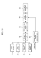
- FIG. 10 is a block diagram to describe the configuration of a vehicle-mounted image processing device of Embodiment 2
- FIG. 11 is a flowchart to describe a switching method of display
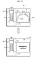
- FIG. 12 illustrates an image to describe exemplary switching of the display.
- the same reference numerals are assigned to elements similar to those in Embodiment 1, and the detailed descriptions thereon are omitted.
- the present embodiment has a feature in that a user is allowed to switch the display of a synthesized image.
- the vehicle-mounted image processing device includes a display switching request acquisition unit 16 to acquire a request for display switching from a user.
- the display switching request acquisition unit 16 determines the presence or not of a request for display switching from a user (Step S201), and when a request is present (YES at Step S201), an instruction is issued to the image synthesis unit 14 to switch the display (Step S202), and when no request is present (NO at Step S201), display switching is not instructed.
- the image synthesis unit 14 synthesizes a bird's eye view image and a through-image to generate a synthesized image 31. Then, when an input for display switching request is received from the display switching request acquisition unit 16 that acquired the display switching request, then the image synthesis unit synthesizes the bird's eye view image and a navigation screen (screen indicating map information and vehicle position information) to generate a synthesized image 32. These synthesized images 31 and 32 are selectively displayed on an in-vehicle monitor (not illustrated). This example describes the case where a bird's eye view image and a navigation screen are displayed as an example of the synthesized image 32, and through-image and a navigation screen may be synthesized.
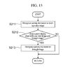
- FIG. 13 is a flowchart to describe another exemplary method for recognizing of the parking line.
- the parking line recognition unit 15 determines whether the current display on the in-vehicle monitor shows a synthesized image of the bird's eye view image and a through-image or not (Step S212). Then when it is determined that the display shows a synthesized image of the bird's eye view image and a through-image (YES at Step S212), the parking line recognition unit recognizes a parking line based on the through-image (Step S213).
- the parking line recognition unit continuously performs recognition of a parking line based on the bird's eye view image.
- the present embodiment includes a system allowing a user to select any monitor display image from a plurality of display contents, for example, and a device where an input image of the vehicle-mounted image processing device is the same as the monitor display screen, where a parking line can be recognized in accordance with the state of the display screen.
- Embodiment 3 of the present invention the following describes Embodiment 3 of the present invention.
- FIG. 14 is a block diagram to describe the configuration of a vehicle-mounted image processing device of Embodiment 3
- FIG. 15 is a flowchart to describe an exemplary method for detecting of a pedestrian
- FIG. 16 is a flowchart to describe an exemplary method for detecting of a pedestrian.
- the same reference numerals are assigned to elements similar to those in the above embodiments, and the detailed descriptions thereon are omitted.
- the present embodiment has a feature in that, in addition to parking line recognition of Embodiment 1 as stated above, a pedestrian is detected based on a bird's eye view image and a through-image.
- the vehicle-mounted image processing device includes a pedestrian detection unit 17 to detect a pedestrian based on images taken by the vehicle-mounted cameras 1 to 4.
- the pedestrian detection unit 17 performs first pedestrian detection processing (Step S311) based on a bird's eye view image, and second pedestrian detection processing (Step S312) based on a through-image.
- the first pedestrian detection processing based on a bird's eye view image and the second pedestrian detection processing based on a through-image may be performed using well-known techniques.
- the first pedestrian detection processing to detect a pedestrian based on a bird's eye view image may be based on a method using an optical flow described in JP 2011-77772 A (Patent Literature 2)
- the second pedestrian detection processing to detect a pedestrian based on a through-image may be based on a method using an optical flow described in JP 2010-146478 A (Patent Literature 3).
- FIG. 16 is a flowchart to describe another exemplary method for detecting of a pedestrian.
- the pedestrian detection unit 17 firstly acquires information on vehicle speed vsp (Step S321), and determines whether the vehicle speed vsp exceeds a predetermined threshold thvsp2 or not (Step S322).
- the second pedestrian detection processing based on a through-image is performed.
- the vehicle speed vsp is the threshold thvsp2 or less (NO at Step S322)
- the first pedestrian detection processing based on a bird's eye view image is performed (Step S324).
- the configuration example of FIG. 16 performs the second parking line recognition processing based on a through-image only when the vehicle speed of the vehicle 10 is high, and so can detect a pedestrian to a more distant area that is wider than the bird's eye view image.
- Embodiment 4 of the present invention the following describes Embodiment 4 of the present invention.
- FIG. 17 is a block diagram to describe the configuration of a vehicle-mounted image processing device of Embodiment 4
- FIG. 18 is a flowchart to describe a scheduling method
- FIG. 19 illustrates an exemplary use allocation rate of a CPU.
- the same reference numerals are assigned to elements similar to those in the above embodiments, and the detailed descriptions thereon are omitted.
- the present embodiment has a feature in that a scheduling unit 18 is added to the configuration of Embodiment 3.
- the vehicle-mounted image processing device includes the scheduling unit 18 that determines whether outside recognition processing by an outside recognition unit is to be performed or not based on the vehicle speed.
- the scheduling unit 18 acquires information on vehicle speed vsp (Step S411), and determines whether the vehicle speed vsp is a predetermined threshold th_vlow or lower or not (Step S412). Then, when it is determined that the vehicle speed vsp is the predetermined threshold th_vlow or lower (YES at STEP S412), both of the parking line recognition processing and the pedestrian detection processing are performed (Step S413). On the other hand, when it is determined that the vehicle speed vsp is higher the threshold th_vlow (NO at STEP S412), the parking line recognition processing only is performed (Step S414).
- the vehicle-mounted image processing device has a CPU as hardware, having a first image processing circuit made up of a chip for image processing only and a second image processing circuit made up of a general-purpose chip, for example.
- the scheduling unit 18 allocates a use rate to the first image processing circuit and the second image processing circuit in accordance with the vehicle-speed condition.
- both of the parking line recognition processing and the pedestrian detection processing are performed at Step S413, where use allocation is performed so that the first image processing circuit performs all (100%) of the pedestrian detection processing and the second image processing circuit performs all (100%) of the parking line recognition processing.
- Step S414 use allocation is performed so that the first image processing circuit performs 50% of the parking line recognition processing and the second image processing circuit performs the remaining 50% of the parking line recognition processing.
- the present embodiment can allocate different processing to each of the chips when two applications are simultaneously operated, whereby their simultaneous operation can be implemented. When only one application is operated, the two chips are used appropriately to shorten the processing cycle.
- Embodiment 5 of the present invention Referring next to FIGs. 20 to 24 , the following describes Embodiment 5 of the present invention.
- FIG. 20 is a block diagram to describe the configuration of a vehicle-mounted image processing device of Embodiment 5
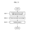
- FIG. 21 is a flowchart to describe a lane departure prediction method
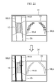
- FIG. 22 illustrates an image to describe a lane departure prediction method.
- the same reference numerals are assigned to elements similar to those in the above embodiments, and the detailed descriptions thereon are omitted.
- the present embodiment has a feature in that a lane departure prediction unit 19 is provided instead of the pedestrian detection unit 17 of Embodiment 4.
- the vehicle-mounted image processing device includes the lane departure prediction unit 19.
- the lane departure prediction unit 19 performs lane departure prediction processing to predict departure of the vehicle 10 from a traveling lane during traveling.
- the lane departure prediction unit 19 recognizes a lane based on a through-image (Step S511), and projects a result thereof on a bird's eye view image (Step S512).
- a lane can be recognized based on a through-image by a well-known technique.
- departure from the traveling lane of the vehicle is predicted based on the bird's eye view image (Step S513). For instance, when the vehicle 10 approaches the traveling lane during traveling to be at a preset distance, the lane departure prediction unit predicts the departure of the vehicle from the traveling lane.
- the lane recognition at Step S511 results in recognition of two traveling lanes WL5 and WL6 extending in the traveling direction of the vehicle 10 on a through-image 22 of a synthesized image 31. Then at Step S512, the traveling lanes WL5 and WL6 recognized in the through-image 22 are projected on a bird's eye view image 25 on a synthesized image 31', and at Step S513, lane departure is predicted based on the bird's eye view image 25.
- the bird's eye view image 25 is easily handled in terms of image processing compared with the through-image 22. That is, lane departure can be predicted more speedily and precisely based on the bird's eye view image 25 than the through-image 22.
- FIG. 23 is a flowchart to describe a scheduling method
- FIG. 24 illustrates an exemplary use allocation rate of a CPU.
- the scheduling unit 18 acquires information on vehicle speed vsp (Step S521), and determines whether the vehicle speed vsp is a predetermined low-speed threshold th_vlow or lower or not (Step S522). Then, when it is determined that the vehicle speed vsp is the low-speed threshold th_vlow or lower (YES at STEP S522), the parking line recognition processing only is performed (Step S523).
- Step S524 determination is made whether the vehicle speed vsp is a high-speed threshold th_vhigh or lower or not (Step S524). Then when it is determined that the vehicle speed vsp is the high-speed threshold th_vhigh or less (YES at STEP S524), both of the parking line recognition processing and the lane departure prediction processing are performed (Step S525). On the other hand, when it is determined that the vehicle speed vsp is higher than the high-speed threshold th_vhigh (NO at STEP S524), the lane departure prediction processing only is performed (Step S526).
- the vehicle-mounted image processing device has a CPU as hardware, having a first image processing circuit made up of a chip for image processing only and a second image processing circuit made up of a general-purpose chip, for example.
- the scheduling unit 18 allocates a use rate to the first image processing circuit and the second image processing circuit in accordance with the vehicle-speed condition.
- Step S523 when the vehicle speed vsp is the low-speed threshold th_vlow or less, the parking line recognition processing only is performed at Step S523, where use allocation is performed so that the first image processing circuit performs 50% of the parking line recognition processing and the second image processing circuit performs the remaining 50% of the parking line recognition processing.
- both of the parking line recognition processing and the lane departure prediction processing are performed at Step S525, where use allocation is performed so that the first image processing circuit performs all (100%) of the parking line recognition processing and the second image processing circuit performs all (100%) of the lane departure prediction processing.
- Step S526 the lane departure prediction processing only is performed at Step S526, where use allocation is performed so that the first image processing circuit performs 50% of the lane departure prediction processing and the second image processing circuit performs the remaining 50% of the lane departure prediction processing.
- the present embodiment can allocate different processing to each of the chips when two applications are simultaneously operated, whereby their simultaneous operation can be implemented. When only one application is operated, the two chips are used appropriately to shorten the processing cycle.
Landscapes
- Engineering & Computer Science (AREA)
- Multimedia (AREA)
- Physics & Mathematics (AREA)
- General Physics & Mathematics (AREA)
- Mechanical Engineering (AREA)
- Theoretical Computer Science (AREA)
- Human Computer Interaction (AREA)
- Image Processing (AREA)
- Image Analysis (AREA)
- Traffic Control Systems (AREA)
- Closed-Circuit Television Systems (AREA)
Abstract
Description
- The present invention relates to a vehicle-mounted image processing device that recognizes the outside of a vehicle based on an image taken by a vehicle-mounted camera.
-
Patent Literature 1, for example, discloses a technique of taking an image of the surrounding of a vehicle as a whole using each of four cameras mounted on the vehicle on the front, rear, left and right, converting and combining these through-images to create a bird's eye view image, and recognizing a parking line based on the bird's eye view image. -
- Patent Literature 1:
JP 2011-301140 A - Patent Literature 2:
JP 2011-77772 A - Patent Literature 3:
JP 2010-146478 A - Typically apparatuses to provide a user with a bird's eye view image provide both of a bird's eye view image and a through-image in the vehicle traveling direction. This is because while a bird's eye view image is suitable for a driver to recognize surroundings of the vehicle, a through-image is more suitable to understand a remote place and a three-dimensional object.
- This applies to an apparatus implementing an application to recognize the outside of a vehicle by image processing for driver supporting as well, when an image to be provided to a user is processed so as to reduce the processing load and simplify the configuration of the apparatus. A bird's eye view image of the images to be provided to a user has a narrow viewing field (about 2 m in the front of the vehicle) as compared with a through-image that is not subjected to processing, and so such an image is not suitable to recognize a remote place. For instance, for the purpose of recognizing a parking line in a relatively high vehicle speed at a highway service area, there is a need to recognize a parking line that is far away from the viewing field of a bird's eye view image.
- On the other hand, a through-image has a wider viewing field than that of a bird's eye view image, and can recognize a remote place, and so typically image processing is often performed based on a through-image to recognize a lane, for example. Meanwhile a bird's eye view image is easily processed compared with a through-image not subjected to conversion, and for example, it is easier to perform calculation, such as departure prediction from a white line, based on a bird's eye view image. In this way, precision for recognition may be improved in some applications by using a bird's eye view image.
- In view of these points, the present invention aims to provide a vehicle-mounted image processing device capable of recognizing the outside of a vehicle based on an image taken by a vehicle-mounted camera more precisely.
- In order to solve these problems, a vehicle-mounted image processing device of the present invention includes: an image acquisition unit that acquires through-images taken by cameras disposed on front, rear and sides of a vehicle; a bird's eye view image generation unit that converts the acquired through images to generate a bird's eye view image; a parking line recognition unit that performs parking line recognition processing to recognize a parking line based on at least one of the through-images and the bird's eye view image. The parking line recognition unit performs first parking line recognition processing based on the bird's eye view image to recognize a parking line in a predetermined range of the bird's eye view image, and second parking line recognition processing based on the through-images to recognize a parking line in an area that is far away from the predetermined range of the bird's eye view image.
- A vehicle-mounted image processing device of the present invention recognizes a parking line in a predetermined range based on a bird's eye view image, and recognizes a parking line in an area far away from the predetermined range of the bird's eye view image based on a through-image, and so can perform image processing based on an appropriate image depending on the situation and can recognize the parking line more precisely. Problems, configurations, and advantageous effects other than those described above will be made clear by the following description of embodiments.
-
-
FIG. 1 is a block diagram to describe the configuration of a vehicle-mounted image processing device ofEmbodiment 1. -
FIG. 2 illustrates an image to describe the configuration of a bird's eye view image generation unit -
FIG. 3 is a flowchart to describe a method of synthesizing an image for recognition of a parking line. -
FIG. 4 illustrates an image where a bird's eye view image and a rear camera image are synthesized. -
FIG. 5 illustrates an image where a bird's eye view image and a front camera image are synthesized. -
FIG. 6 is a flowchart to describe an exemplary method for recognizing of a parking line. -
FIG. 7 is a flowchart to describe a method for recognizing of a parking line based on a bird's eye view image. -
FIG. 8 is a flowchart to describe a method for recognizing of a parking line based on a through-image. -
FIG. 9 is a flowchart to describe another exemplary method for recognizing of a parking line. -
FIG. 10 is a block diagram to describe the configuration of a vehicle-mounted image processing device ofEmbodiment 2. -
FIG. 11 is a flowchart to describe a switching method of display. -
FIG. 12 illustrates an image to describe exemplary switching of the display. -
FIG. 13 is a flowchart to describe another exemplary method for recognizing of a parking line. -
FIG. 14 is a block diagram to describe the configuration of a vehicle-mounted image processing device ofEmbodiment 3. -
FIG. 15 is a flowchart to describe an exemplary method for detecting of a pedestrian. -
FIG. 16 is a flowchart to describe an exemplary method for detecting of a pedestrian. -
FIG. 17 is a block diagram to describe the configuration of a vehicle-mounted image processing device ofEmbodiment 4. -
FIG. 18 is a flowchart to describe a scheduling method. -
FIG. 19 illustrates an exemplary use allocation rate of a CPU. -
FIG. 20 is a block diagram to describe the configuration of a vehicle-mounted image processing device of Embodiment 5. -
FIG. 21 is a flowchart to describe a lane departure prediction method. -
FIG. 22 illustrates an image to describe a lane departure prediction method. -
FIG. 23 is a flowchart to describe a scheduling method. -
FIG. 24 illustrates an exemplary use allocation rate of a CPU. - The following describes embodiments of the present invention, with reference to the drawings.
-
FIG. 1 is a block diagram to describe the configuration of a vehicle-mounted image processing device of the present embodiment, andFIG. 2 illustrates an image to describe the configuration of a bird's eye view image generation unit. - The vehicle-mounted image processing device is implemented by hardware and software in a camera device mounted on a
vehicle 10. The vehicle-mounted image processing device includes animage acquisition unit 12, a bird's eye viewimage generation unit 13, animage synthesis unit 14, and a parkingline recognition unit 15 as its internal functions. - The
image acquisition unit 12 acquires through-images taken by afront camera 1, arear camera 2, aright side camera 3, and aleft side camera 4 that are attached on the front, the rear, the right side and the left side, respectively, of thevehicle 10. - The bird's eye view
image generation unit 13 converts the through-images acquired by theimage acquisition unit 12 to generate a bird'seye view image 25 having a point of view that is shifted to the above of thevehicle 10. The bird'seye view image 25 is generated using a well-known technique. Theimage synthesis unit 14 synthesizes at least one of the through-images and a bird's eye view image. The parkingline recognition unit 15 as an outside recognition unit performs processing to recognize the outside parking line WL from the synthesized image synthesized by theimage synthesis unit 14 and based on at least one of the through-images and the bird's eye view image. - In the example of
FIG. 2 , images of the state where thevehicle 10 enters the parking line WL from the front are taken by thecameras 1 to 4. The parking line WL is defined with marking lines WL1 to WL3 using white or yellow paint for partitioning of the area for one vehicle. - The parking line WL includes marking lines WL1 and WL2 for partitioning of both sides in the vehicle width direction, and a marking line WL3 for partitioning in the vehicle front-rear direction. Each through-
image 21 to 24 shows the parking line WL located around the vehicle. Then, the bird'seye view image 25 that is generated by converting the through-images 21 to 24 shows the marking lines WL1 and WL2 and the marking line WL3 on the front side of the vehicle that surround thevehicle 10. -
FIG. 3 is a flowchart to describe a method of synthesizing an image for recognition of the parking line,FIG. 4 illustrates an image where a bird's eye view image and a rear camera image are synthesized, andFIG. 5 illustrates an image where a bird's eye view image and a front camera image are synthesized. - The
image synthesis unit 14 acquires shift position information on the vehicle 10 (Step S101). The shift position information is acquired from a controller to control a driving system of thevehicle 10 via a CAN, for example. The shift position information contains information on the position of a shift of thevehicle 10, for example, in the case of a manual transmission, the position of a shift lever, and in the case of an automatic transmission, the position of a selector lever. - Then, determination is made based on the shift position information whether the position of reverse R is selected or not (Step S102). When the position of reverse R is selected (YES at Step S102), a bird's
eye view image 25 and a through-image 22 of therear camera 2 are synthesized (Step S103). When the position other than reverse R is selected (NO at Step S102), the bird'seye view image 25 and a through-image 21 of thefront camera 1 are synthesized (Step S104). Note here that although one through-image and a bird's eye view image are synthesized in this example, a plurality of through-images and a bird's eye view image may be synthesized. -
FIG. 6 is a flowchart to describe an exemplary method for recognizing of the parking line,FIG. 7 is a flowchart to describe a method for recognizing of the parking line based on a bird's eye view image, andFIG. 8 is a flowchart to describe a method for recognizing of the parking line based on a through-image - The parking
line recognition unit 15 firstly performs first parking line recognition processing to recognize a parking line based on a bird's eye view image 25 (Step S111), and then performs second parking line recognition processing to recognize the parking line based on a through- image (Step S112). - As illustrated in
FIG. 7 , the first parking line recognition processing firstly applies an edge filter in the horizontal direction for all lines (Step S121) and extracts peaks (rising and falling) (Step S122). Then edges having a pair of rising and falling at a predetermined interval only are left (Step S123), which are grouped (Step S124), and filtering is performed for length (Step S125). Then, coordinates of the upper limits and the lower limits of a rising edge and a falling edge are extracted (Step S126) to select two white lines (marking lines) (Step S127). - Then, determinations are made whether the thus selected two white lines have a difference in angle of a predetermined value or less (to Thθmax) (Step S128), whether the distance between the two white lines is within a predetermined range (from ThWmin to ThWmax) or not (Step S129) and displacement between the lower limits of the two white lines is within a predetermined range (ThBmin to ThBmax) or not (Step S130). Then when all of the conditions at Steps S129 to S130 hold, the procedure shifts to Step S131. At Step S131, coordinate positions of the points of four corners of the parking line WL, i.e., the upper end and the lower end of the white line (marking line WL2) on the left of the vehicle and the upper end and the lower end of the white line (marking line WL1) on the right of the vehicle are registered.
- Then determination is made whether all combinations are checked or not (Step S132), and when they are checked (YES at Step S132), the first parking line recognition processing ends. When they are not checked (NO at Step S132), the procedure returns to the processing to select two white lines (Step S127), and the following processing is repeatedly performed until it is determined that all of the combinations are checked (YES at Step S132).
- As illustrated in
FIG. 8 , the second parking line recognition processing firstly sets an image processing area (Step S141). The image processing area is set so as to process an area that is far away from the bird'seye view image 25 only. Then similarly to Steps S121 and S122 in the method for recognizing of a parking line based on a bird's eye view image, an edge filter in the horizontal direction is applied for all lines (Step S142) peaks (rising and falling) are extracted (Step S143). Then bird's eye view conversion is performed using camera geometry for all edge points (Step S144). Then the processing similar to Steps S123 to S132 in the method for recognizing of a parking line based on a bird's eye view image is performed (Steps S145 to S154), and the second parking line recognition processing ends. - The vehicle-mounted image processing device in the present embodiment recognizes a parking line using both of a bird's eye view image and a through-image, and so as compared with the case of using a bird's eye view image only, a parking line can be recognized to a more distant area.
-
FIG. 9 is a flowchart to describe another exemplary method for recognizing of the parking line. - In the parking line recognition method as stated above, both of the first parking line recognition processing and the second parking line recognition processing are always performed. Instead, it may be configured so that selection may be made as needed between the case of parking line recognition based on both of the first parking line recognition processing and the second parking line recognition processing and the case where only one of the first parking line recognition processing and the second parking line recognition processing is performed.
- As illustrated as modification example 1 in
FIG. 9 , the parkingline recognition unit 15 firstly performs the first parking line recognition processing to recognize a parking line based on a bird's eye view image 25 (Step S161). Then, information on vehicle speed vsp of thevehicle 10 is acquired (Step S162), and determination is made whether the vehicle speed vsp is higher than a predetermined threshold thvsp1 or not (Step S163). - When it is determined that the vehicle speed vsp is higher than the predetermined threshold thvsp1 (YES at Step S163), the second parking line recognition processing is performed based on a through-image, and when the vehicle speed vsp is the threshold thvsp1 or lower (NO at Step S163), the procedure ends.
- The configuration example of
FIG. 9 performs both of the first parking line recognition processing based on a bird's eye view image and the second parking line recognition processing based on a through-image when the vehicle speed of thevehicle 10 is high, and so can recognize a parking line to a more distant area that is wider than the bird's eye view image. On the other hand, when the vehicle speed is low, the first parking line recognition processing based on a bird's eye view image only is performed, and the second parking line recognition processing based on a through-image is not performed, and so the calculation processing load corresponding to the second parking line recognition processing can be reduced, which can be used for calculation of other applications, for example. In this way hardware resources can be effectively used. The calculation processing load corresponding to the second parking line recognition processing may be used for the first parking line recognition processing based on a bird's eye view image for precise recognition of the parking line. - Referring next to
FIGs. 10 to 13 , the following describesEmbodiment 2 of the present invention. -
FIG. 10 is a block diagram to describe the configuration of a vehicle-mounted image processing device ofEmbodiment 2,FIG. 11 is a flowchart to describe a switching method of display, andFIG. 12 illustrates an image to describe exemplary switching of the display. The same reference numerals are assigned to elements similar to those inEmbodiment 1, and the detailed descriptions thereon are omitted. - The present embodiment has a feature in that a user is allowed to switch the display of a synthesized image.
- As illustrated in
FIG. 10 , the vehicle-mounted image processing device includes a display switchingrequest acquisition unit 16 to acquire a request for display switching from a user. As illustrated inFIG. 11 , the display switchingrequest acquisition unit 16 determines the presence or not of a request for display switching from a user (Step S201), and when a request is present (YES at Step S201), an instruction is issued to theimage synthesis unit 14 to switch the display (Step S202), and when no request is present (NO at Step S201), display switching is not instructed. - For instance, as illustrated in
FIG. 12 , theimage synthesis unit 14 synthesizes a bird's eye view image and a through-image to generate asynthesized image 31. Then, when an input for display switching request is received from the display switchingrequest acquisition unit 16 that acquired the display switching request, then the image synthesis unit synthesizes the bird's eye view image and a navigation screen (screen indicating map information and vehicle position information) to generate asynthesized image 32. Thesesynthesized images image 32, and through-image and a navigation screen may be synthesized. -
FIG. 13 is a flowchart to describe another exemplary method for recognizing of the parking line. - When a parking line is recognized based on a bird's eye view image (Step S211), the parking
line recognition unit 15 determines whether the current display on the in-vehicle monitor shows a synthesized image of the bird's eye view image and a through-image or not (Step S212). Then when it is determined that the display shows a synthesized image of the bird's eye view image and a through-image (YES at Step S212), the parking line recognition unit recognizes a parking line based on the through-image (Step S213). On the other hand, when it is determined that the current display does not show a synthesized image of the bird's eye view image and a through-image (NO at Step S212), the parking line recognition unit continuously performs recognition of a parking line based on the bird's eye view image. - The present embodiment includes a system allowing a user to select any monitor display image from a plurality of display contents, for example, and a device where an input image of the vehicle-mounted image processing device is the same as the monitor display screen, where a parking line can be recognized in accordance with the state of the display screen.
- Referring next to
FIGs. 14 to 16 , the following describesEmbodiment 3 of the present invention. -
FIG. 14 is a block diagram to describe the configuration of a vehicle-mounted image processing device ofEmbodiment 3,FIG. 15 is a flowchart to describe an exemplary method for detecting of a pedestrian, andFIG. 16 is a flowchart to describe an exemplary method for detecting of a pedestrian. The same reference numerals are assigned to elements similar to those in the above embodiments, and the detailed descriptions thereon are omitted. - The present embodiment has a feature in that, in addition to parking line recognition of
Embodiment 1 as stated above, a pedestrian is detected based on a bird's eye view image and a through-image. - As illustrated in
FIG. 14 , the vehicle-mounted image processing device includes apedestrian detection unit 17 to detect a pedestrian based on images taken by the vehicle-mountedcameras 1 to 4. As illustrated inFIG. 15 , thepedestrian detection unit 17 performs first pedestrian detection processing (Step S311) based on a bird's eye view image, and second pedestrian detection processing (Step S312) based on a through-image. - The first pedestrian detection processing based on a bird's eye view image and the second pedestrian detection processing based on a through-image may be performed using well-known techniques. For instance, the first pedestrian detection processing to detect a pedestrian based on a bird's eye view image may be based on a method using an optical flow described in
JP 2011-77772 A JP 2010-146478 A -
FIG. 16 is a flowchart to describe another exemplary method for detecting of a pedestrian. - As illustrated in
FIG. 16 as a modification example, thepedestrian detection unit 17 firstly acquires information on vehicle speed vsp (Step S321), and determines whether the vehicle speed vsp exceeds a predetermined threshold thvsp2 or not (Step S322). - When it is determined the vehicle speed vsp exceeds the predetermined threshold thvsp2 (YES at Step S322), the second pedestrian detection processing based on a through-image is performed. When it is determined the vehicle speed vsp is the threshold thvsp2 or less (NO at Step S322), the first pedestrian detection processing based on a bird's eye view image is performed (Step S324).
- The configuration example of
FIG. 16 performs the second parking line recognition processing based on a through-image only when the vehicle speed of thevehicle 10 is high, and so can detect a pedestrian to a more distant area that is wider than the bird's eye view image. - Referring next to
FIGs. 17 to 19 , the following describesEmbodiment 4 of the present invention. -
FIG. 17 is a block diagram to describe the configuration of a vehicle-mounted image processing device ofEmbodiment 4,FIG. 18 is a flowchart to describe a scheduling method, andFIG. 19 illustrates an exemplary use allocation rate of a CPU. The same reference numerals are assigned to elements similar to those in the above embodiments, and the detailed descriptions thereon are omitted. - The present embodiment has a feature in that a
scheduling unit 18 is added to the configuration ofEmbodiment 3. - As illustrated in
FIG. 17 , the vehicle-mounted image processing device includes thescheduling unit 18 that determines whether outside recognition processing by an outside recognition unit is to be performed or not based on the vehicle speed. - As illustrated in
FIG. 18 , thescheduling unit 18 acquires information on vehicle speed vsp (Step S411), and determines whether the vehicle speed vsp is a predetermined threshold th_vlow or lower or not (Step S412). Then, when it is determined that the vehicle speed vsp is the predetermined threshold th_vlow or lower (YES at STEP S412), both of the parking line recognition processing and the pedestrian detection processing are performed (Step S413). On the other hand, when it is determined that the vehicle speed vsp is higher the threshold th_vlow (NO at STEP S412), the parking line recognition processing only is performed (Step S414). - The vehicle-mounted image processing device has a CPU as hardware, having a first image processing circuit made up of a chip for image processing only and a second image processing circuit made up of a general-purpose chip, for example. The
scheduling unit 18 allocates a use rate to the first image processing circuit and the second image processing circuit in accordance with the vehicle-speed condition. - For instance, as illustrated in
FIG. 19 , when the vehicle speed vsp is a threshold th_vlow or less, both of the parking line recognition processing and the pedestrian detection processing are performed at Step S413, where use allocation is performed so that the first image processing circuit performs all (100%) of the pedestrian detection processing and the second image processing circuit performs all (100%) of the parking line recognition processing. - When the vehicle speed vsp is higher than the threshold th_vlow, the parking line recognition processing only is performed at Step S414, where use allocation is performed so that the first image processing circuit performs 50% of the parking line recognition processing and the second image processing circuit performs the remaining 50% of the parking line recognition processing.
- The present embodiment can allocate different processing to each of the chips when two applications are simultaneously operated, whereby their simultaneous operation can be implemented. When only one application is operated, the two chips are used appropriately to shorten the processing cycle.
- Referring next to
FIGs. 20 to 24 , the following describes Embodiment 5 of the present invention. -
FIG. 20 is a block diagram to describe the configuration of a vehicle-mounted image processing device of Embodiment 5,FIG. 21 is a flowchart to describe a lane departure prediction method, andFIG. 22 illustrates an image to describe a lane departure prediction method. The same reference numerals are assigned to elements similar to those in the above embodiments, and the detailed descriptions thereon are omitted. - The present embodiment has a feature in that a lane
departure prediction unit 19 is provided instead of thepedestrian detection unit 17 ofEmbodiment 4. - As illustrated in
FIG. 20 , the vehicle-mounted image processing device includes the lanedeparture prediction unit 19. The lanedeparture prediction unit 19 performs lane departure prediction processing to predict departure of thevehicle 10 from a traveling lane during traveling. - As illustrated in
FIG. 21 , the lanedeparture prediction unit 19 recognizes a lane based on a through-image (Step S511), and projects a result thereof on a bird's eye view image (Step S512). A lane can be recognized based on a through-image by a well-known technique. Then, departure from the traveling lane of the vehicle is predicted based on the bird's eye view image (Step S513). For instance, when thevehicle 10 approaches the traveling lane during traveling to be at a preset distance, the lane departure prediction unit predicts the departure of the vehicle from the traveling lane. - As illustrated in
FIG. 22 , the lane recognition at Step S511 results in recognition of two traveling lanes WL5 and WL6 extending in the traveling direction of thevehicle 10 on a through-image 22 of asynthesized image 31. Then at Step S512, the traveling lanes WL5 and WL6 recognized in the through-image 22 are projected on a bird'seye view image 25 on a synthesized image 31', and at Step S513, lane departure is predicted based on the bird'seye view image 25. - The bird's
eye view image 25 is easily handled in terms of image processing compared with the through-image 22. That is, lane departure can be predicted more speedily and precisely based on the bird'seye view image 25 than the through-image 22. -
FIG. 23 is a flowchart to describe a scheduling method, andFIG. 24 illustrates an exemplary use allocation rate of a CPU. - As illustrated in
FIG. 23 , thescheduling unit 18 acquires information on vehicle speed vsp (Step S521), and determines whether the vehicle speed vsp is a predetermined low-speed threshold th_vlow or lower or not (Step S522). Then, when it is determined that the vehicle speed vsp is the low-speed threshold th_vlow or lower (YES at STEP S522), the parking line recognition processing only is performed (Step S523). - On the other hand, when it is determined that the vehicle speed vsp is higher than the low-speed threshold th_vlow (NO at STEP S522), determination is made whether the vehicle speed vsp is a high-speed threshold th_vhigh or lower or not (Step S524). Then when it is determined that the vehicle speed vsp is the high-speed threshold th_vhigh or less (YES at STEP S524), both of the parking line recognition processing and the lane departure prediction processing are performed (Step S525). On the other hand, when it is determined that the vehicle speed vsp is higher than the high-speed threshold th_vhigh (NO at STEP S524), the lane departure prediction processing only is performed (Step S526).
- The vehicle-mounted image processing device has a CPU as hardware, having a first image processing circuit made up of a chip for image processing only and a second image processing circuit made up of a general-purpose chip, for example. The
scheduling unit 18 allocates a use rate to the first image processing circuit and the second image processing circuit in accordance with the vehicle-speed condition. - For instance, as illustrated in
FIG. 24 , when the vehicle speed vsp is the low-speed threshold th_vlow or less, the parking line recognition processing only is performed at Step S523, where use allocation is performed so that the first image processing circuit performs 50% of the parking line recognition processing and the second image processing circuit performs the remaining 50% of the parking line recognition processing. - When the vehicle speed vsp is higher than the low-speed threshold th_vlow and is the high-speed threshold th_vhigh or less, both of the parking line recognition processing and the lane departure prediction processing are performed at Step S525, where use allocation is performed so that the first image processing circuit performs all (100%) of the parking line recognition processing and the second image processing circuit performs all (100%) of the lane departure prediction processing.
- Then when the vehicle speed vsp is higher than the high-speed threshold th_vhigh, the lane departure prediction processing only is performed at Step S526, where use allocation is performed so that the first image processing circuit performs 50% of the lane departure prediction processing and the second image processing circuit performs the remaining 50% of the lane departure prediction processing.
- The present embodiment can allocate different processing to each of the chips when two applications are simultaneously operated, whereby their simultaneous operation can be implemented. When only one application is operated, the two chips are used appropriately to shorten the processing cycle.
- That is a detailed description on the embodiments of the present invention, and the present invention is not limited to the above-described embodiments and may include various modification examples without departing from the spirit of the present invention recited in claims. For instance, the entire detailed configuration of the embodiments described above for explanatory convenience is not always necessary for the present invention. A part of one embodiment may be replaced with the configuration of another embodiment, or the configuration of one embodiment may be added to the configuration of another embodiment. The configuration of each embodiment may additionally include another configuration, or a part of the configuration may be deleted or replaced.
-
- 1 to 4
- Cameras
- 10
- Own vehicle (vehicle)
- 12
- Image acquisition unit
- 13
- Bird's eye view image generation unit
- 14
- Image synthesis unit
- 15
- Parking line recognition unit
- 16
- Display switching request acquisition unit
- 17
- Pedestrian detection unit
- 18
- Scheduling unit
- 19
- Lane departure prediction unit
- 21 to 24
- Through-images
- 25
- Bird's eye view image
- WL
- Parking line
- WL1 to WL3
- Marking lines
- WL5, WL6
- Traveling lines
Claims (6)
- A vehicle-mounted image processing device, comprising:an image acquisition unit that acquires through-images taken by cameras disposed on front, rear and sides of a vehicle;a bird's eye view image generation unit that converts the acquired through images to generate a bird's eye view image;a parking line recognition unit that performs parking line recognition processing to recognize a parking line based on at least one of the through-images and the bird's eye view image, whereinthe parking line recognition unit performs first parking line recognition processing based on the bird's eye view image to recognize a parking line in a predetermined range of the bird's eye view image, and second parking line recognition processing based on the through-images to recognize a parking line in an area that is far away from the predetermined range of the bird's eye view image.
- The vehicle-mounted image processing device according to claim 1, wherein when a speed of the vehicle is a preset threshold or less, the parking line recognition unit performs the first parking line recognition processing, and when a speed of the vehicle is higher than the threshold, the parking line recognition unit performs the first parking line recognition processing and the second parking line recognition processing.
- The vehicle-mounted image processing device according to claim 1, further comprising an in-vehicle monitor that can selectively display a synthesized image of the bird's eye view image and the through-images in accordance with a display switching request from a user, wherein
when the parking line recognition unit performs the first parking line recognition processing and the synthesized image is selected and displayed on the in-vehicle monitor, the parking line recognition unit performs the second parking line recognition processing instead of the first parking line recognition processing. - The vehicle-mounted image processing device according to claim 1, further comprising:a pedestrian detection unit that detects a pedestrian based on at least one of the through-images and the bird's eye view image; anda scheduling unit that determines whether to execute parking line recognition processing by the parking line recognition unit or pedestrian detection processing by the pedestrian detection unit in accordance with the vehicle speed, whereinwhen the vehicle speed is a preset threshold or less, the scheduling unit makes the parking line recognition unit perform parking line recognition processing and the pedestrian detection unit perform pedestrian detection processing, andwhen the vehicle speed is higher than the threshold, the scheduling unit makes the parking line recognition unit only perform parking line recognition processing.
- The vehicle-mounted image processing device according to claim 4, further comprising: a first image processing circuit and a second image processing circuit, wherein
when the vehicle speed is the threshold or less, the scheduling unit makes any one of the first image processing circuit and the second image processing circuit perform pedestrian detection processing by the pedestrian detection unit and makes the other of the first image processing circuit and the second image processing circuit perform parking line recognition processing by the parking line recognition unit, and
when the vehicle speed is higher than the threshold, the scheduling unit makes the first image processing circuit perform a part of the parking line recognition processing by the parking line recognition unit and makes the second image processing circuit perform remaining of the parking line recognition processing by the parking line recognition unit. - The vehicle-mounted image processing device according to claim 1, further comprising:a lane recognition unit that recognizes a vehicle traveling lane based on at least one of the through-images and the bird's eye view image; anda scheduling unit that determines whether to execute parking line recognition processing by the parking line recognition unit or lane recognition processing by the lane recognition unit in accordance with the vehicle speed, whereinwhen the vehicle speed is a preset first threshold or less, the scheduling unit makes the parking line recognition unit only perform parking line recognition processing,when the vehicle speed is higher than the first threshold and a preset second threshold or less, the scheduling unit makes the parking line recognition unit perform parking line recognition processing and the lane recognition unit perform lane recognition processing, andwhen the vehicle speed is higher than the second threshold, the scheduling unit makes the lane recognition unit only perform lane recognition processing.
Applications Claiming Priority (2)
| Application Number | Priority Date | Filing Date | Title |
|---|---|---|---|
| JP2012258984 | 2012-11-27 | ||
| PCT/JP2013/081898 WO2014084256A1 (en) | 2012-11-27 | 2013-11-27 | Vehicle-mounted image processing device |
Publications (3)
| Publication Number | Publication Date |
|---|---|
| EP2927863A1 true EP2927863A1 (en) | 2015-10-07 |
| EP2927863A4 EP2927863A4 (en) | 2016-08-24 |
| EP2927863B1 EP2927863B1 (en) | 2020-03-04 |
Family
ID=50827888
Family Applications (1)
| Application Number | Title | Priority Date | Filing Date |
|---|---|---|---|
| EP13859419.7A Active EP2927863B1 (en) | 2012-11-27 | 2013-11-27 | Vehicle-mounted image processing device |
Country Status (5)
| Country | Link |
|---|---|
| US (1) | US9715633B2 (en) |
| EP (1) | EP2927863B1 (en) |
| JP (1) | JP5921715B2 (en) |
| CN (1) | CN104871204B (en) |
| WO (1) | WO2014084256A1 (en) |
Cited By (2)
| Publication number | Priority date | Publication date | Assignee | Title |
|---|---|---|---|---|
| EP3389026A1 (en) * | 2017-04-12 | 2018-10-17 | Volvo Car Corporation | Apparatus and method for road vehicle driver assistance |
| EP3503531A1 (en) * | 2017-12-20 | 2019-06-26 | Toyota Jidosha Kabushiki Kaisha | Image display apparatus |
Families Citing this family (14)
| Publication number | Priority date | Publication date | Assignee | Title |
|---|---|---|---|---|
| JP6307895B2 (en) * | 2014-01-23 | 2018-04-11 | トヨタ自動車株式会社 | Vehicle periphery monitoring device |
| DE102014107235A1 (en) * | 2014-05-22 | 2015-11-26 | Dr. Ing. H.C. F. Porsche Aktiengesellschaft | A method of displaying a vehicle environment on a display device; a display device; a system of a plurality of image capture units and a display device; a computer program |
| JP6137081B2 (en) * | 2014-07-29 | 2017-05-31 | 株式会社デンソー | Car equipment |
| JP6206395B2 (en) * | 2014-12-26 | 2017-10-04 | トヨタ自動車株式会社 | Electronic mirror device |
| US10160437B2 (en) * | 2016-02-29 | 2018-12-25 | Magna Electronics Inc. | Vehicle control system with reverse assist |
| JP6572862B2 (en) * | 2016-10-14 | 2019-09-11 | 株式会社デンソー | Display control device |
| DE102018215055A1 (en) * | 2018-09-05 | 2020-03-05 | Bayerische Motoren Werke Aktiengesellschaft | Method for determining a lane change indication of a vehicle, a computer-readable storage medium and a vehicle |
| JP7288793B2 (en) * | 2019-04-25 | 2023-06-08 | フォルシアクラリオン・エレクトロニクス株式会社 | Image processing device and image processing method |
| US11244500B2 (en) | 2019-12-31 | 2022-02-08 | Woven Planet North America, Inc. | Map feature extraction using overhead view images |
| US11037328B1 (en) | 2019-12-31 | 2021-06-15 | Lyft, Inc. | Overhead view image generation |
| US11288522B2 (en) * | 2019-12-31 | 2022-03-29 | Woven Planet North America, Inc. | Generating training data from overhead view images |
| JP7482054B2 (en) | 2020-02-27 | 2024-05-13 | フォルシアクラリオン・エレクトロニクス株式会社 | Image processing device and image processing method |
| CN115210790B (en) * | 2020-08-28 | 2024-11-15 | Jvc建伍株式会社 | Target recognition control device and target recognition method |
| US12254706B2 (en) * | 2021-11-05 | 2025-03-18 | Vinai Artificial Intelligence Application And Research Joint Stock Company | Parking slot detection method and system |
Family Cites Families (31)
| Publication number | Priority date | Publication date | Assignee | Title |
|---|---|---|---|---|
| US5961571A (en) * | 1994-12-27 | 1999-10-05 | Siemens Corporated Research, Inc | Method and apparatus for automatically tracking the location of vehicles |
| US7366595B1 (en) * | 1999-06-25 | 2008-04-29 | Seiko Epson Corporation | Vehicle drive assist system |
| US6734896B2 (en) * | 2000-04-28 | 2004-05-11 | Matsushita Electric Industrial Co., Ltd. | Image processor and monitoring system |
| JP3297040B1 (en) * | 2001-04-24 | 2002-07-02 | 松下電器産業株式会社 | Image composing and displaying method of vehicle-mounted camera and apparatus therefor |
| JP4156214B2 (en) * | 2001-06-13 | 2008-09-24 | 株式会社デンソー | Vehicle periphery image processing apparatus and recording medium |
| JP4067424B2 (en) * | 2003-02-21 | 2008-03-26 | 株式会社デンソー | Vehicle peripheral image processing apparatus, program, and recording medium |
| ES2258399B1 (en) * | 2005-02-04 | 2007-11-16 | Fico Mirrors, S.A. | METHOD AND SYSTEM TO IMPROVE THE SUPERVISION OF AN OUTSIDE ENVIRONMENT OF A MOTOR VEHICLE. |
| DE102005005969A1 (en) * | 2005-02-10 | 2006-08-24 | Robert Bosch Gmbh | Semi-autonomous parking operation assisting method for motor vehicle, involves determining convenient parking operation method in dependence of dimension of parking spot and operating steering automatically up to intermediate position |
| US7415134B2 (en) * | 2005-05-17 | 2008-08-19 | Honda Motor Co., Ltd. | Traffic lane marking line recognition system for vehicle |
| JP4650252B2 (en) * | 2005-12-16 | 2011-03-16 | 株式会社デンソー | Parking assistance device |
| KR101143176B1 (en) * | 2006-09-14 | 2012-05-08 | 주식회사 만도 | Method and Apparatus for Recognizing Parking Slot Marking by Using Bird's Eye View and Parking Assist System Using Same |
| KR20090088210A (en) * | 2008-02-14 | 2009-08-19 | 주식회사 만도 | Target parking position detection method and device using two reference points and parking assistance system using the same |
| JP2010146478A (en) | 2008-12-22 | 2010-07-01 | Toyota Motor Corp | Object detection device |
| JP5068779B2 (en) * | 2009-02-27 | 2012-11-07 | 現代自動車株式会社 | Vehicle surroundings overhead image display apparatus and method |
| JP5210233B2 (en) * | 2009-04-14 | 2013-06-12 | 日立オートモティブシステムズ株式会社 | Vehicle external recognition device and vehicle system using the same |
| JP5627253B2 (en) * | 2009-05-29 | 2014-11-19 | 富士通テン株式会社 | Image processing apparatus, electronic apparatus, and image processing method |
| JP5313072B2 (en) | 2009-07-29 | 2013-10-09 | 日立オートモティブシステムズ株式会社 | External recognition device |
| JP5372680B2 (en) * | 2009-09-24 | 2013-12-18 | 日立オートモティブシステムズ株式会社 | Obstacle detection device |
| JP4970516B2 (en) | 2009-09-30 | 2012-07-11 | 日立オートモティブシステムズ株式会社 | Surrounding confirmation support device |
| JP5401344B2 (en) * | 2010-01-28 | 2014-01-29 | 日立オートモティブシステムズ株式会社 | Vehicle external recognition device |
| US8948990B2 (en) * | 2010-06-25 | 2015-02-03 | Nissan Motor Co., Ltd. | Parking assist control apparatus and control method |
| JP2012025378A (en) | 2010-06-25 | 2012-02-09 | Nissan Motor Co Ltd | Control device and control method for parking support |
| JP5472026B2 (en) * | 2010-06-29 | 2014-04-16 | トヨタ自動車株式会社 | Parking assistance device |
| US9264672B2 (en) * | 2010-12-22 | 2016-02-16 | Magna Mirrors Of America, Inc. | Vision display system for vehicle |
| JP5603835B2 (en) * | 2011-06-27 | 2014-10-08 | クラリオン株式会社 | Vehicle perimeter monitoring device |
| TW201344648A (en) * | 2012-04-30 | 2013-11-01 | Tung Thih Electronic Co Ltd | Driving monitoring system and driving monitoring method |
| US10089537B2 (en) * | 2012-05-18 | 2018-10-02 | Magna Electronics Inc. | Vehicle vision system with front and rear camera integration |
| CN104520913B (en) * | 2012-07-03 | 2016-12-07 | 歌乐株式会社 | Vehicle Environment Recognition Device |
| US9922258B2 (en) * | 2012-11-27 | 2018-03-20 | Clarion Co., Ltd. | On-vehicle image processing apparatus |
| US9892493B2 (en) * | 2014-04-21 | 2018-02-13 | Texas Instruments Incorporated | Method, apparatus and system for performing geometric calibration for surround view camera solution |
| CN104464375B (en) * | 2014-11-20 | 2017-05-31 | 长安大学 | It is a kind of to recognize the method that vehicle high-speed is turned |
-
2013
- 2013-11-27 JP JP2014549863A patent/JP5921715B2/en not_active Expired - Fee Related
- 2013-11-27 WO PCT/JP2013/081898 patent/WO2014084256A1/en not_active Ceased
- 2013-11-27 US US14/647,398 patent/US9715633B2/en active Active
- 2013-11-27 CN CN201380061842.1A patent/CN104871204B/en not_active Expired - Fee Related
- 2013-11-27 EP EP13859419.7A patent/EP2927863B1/en active Active
Cited By (5)
| Publication number | Priority date | Publication date | Assignee | Title |
|---|---|---|---|---|
| EP3389026A1 (en) * | 2017-04-12 | 2018-10-17 | Volvo Car Corporation | Apparatus and method for road vehicle driver assistance |
| CN109367536A (en) * | 2017-04-12 | 2019-02-22 | 沃尔沃汽车公司 | Apparatus and method for driver assistance in road vehicles |
| US10692372B2 (en) | 2017-04-12 | 2020-06-23 | Volvo Car Corporation | Appartus and method for road vehicle driver assistance |
| CN109367536B (en) * | 2017-04-12 | 2021-10-22 | 沃尔沃汽车公司 | Apparatus and method for driver assistance in road vehicles |
| EP3503531A1 (en) * | 2017-12-20 | 2019-06-26 | Toyota Jidosha Kabushiki Kaisha | Image display apparatus |
Also Published As
| Publication number | Publication date |
|---|---|
| JPWO2014084256A1 (en) | 2017-01-05 |
| WO2014084256A1 (en) | 2014-06-05 |
| EP2927863B1 (en) | 2020-03-04 |
| CN104871204A (en) | 2015-08-26 |
| US9715633B2 (en) | 2017-07-25 |
| EP2927863A4 (en) | 2016-08-24 |
| JP5921715B2 (en) | 2016-05-24 |
| CN104871204B (en) | 2018-01-26 |
| US20150310285A1 (en) | 2015-10-29 |
Similar Documents
| Publication | Publication Date | Title |
|---|---|---|
| EP2927863B1 (en) | Vehicle-mounted image processing device | |
| EP3422323B1 (en) | Information processing apparatus | |
| JP6407626B2 (en) | Object recognition device and vehicle control system | |
| JP6313646B2 (en) | External recognition device | |
| CN106030679B (en) | Vehicle surroundings monitoring apparatus | |
| CN110831819B (en) | Parking assist method and parking assist device | |
| CN108266033A (en) | Automatic parking system and automatic parking method | |
| US10163348B2 (en) | Drive assist device | |
| JPWO2018096644A1 (en) | VEHICLE DISPLAY CONTROL DEVICE, VEHICLE DISPLAY CONTROL METHOD, AND VEHICLE DISPLAY CONTROL PROGRAM | |
| CN102171743A (en) | Information processing device associated with vehicle traveling | |
| US10209857B2 (en) | Display control apparatus and display system | |
| CN108944919A (en) | The method and system with the perception scene figure of focal zone is generated for motor vehicles | |
| KR102713185B1 (en) | A camera system for ADAS, system and method for intersection collision avoidance | |
| KR102766243B1 (en) | A camera system for ADAS, System and Method for Autonomous Emergency Braking | |
| EP3495222A1 (en) | Image-capturing device | |
| KR20180085545A (en) | A camera system for ADAS, And Apparatus and Method for controlling vehicle | |
| JP2005267120A (en) | Peripheral vehicle distinguishing method, and travel support system using it | |
| WO2015190052A1 (en) | Preceding condition determination apparatus | |
| EP2720211A1 (en) | Other-vehicle detection device and other-vehicle detection method | |
| JP7619336B2 (en) | Display control device, display control computer program, and display control method | |
| JP7129147B2 (en) | Vehicle device, safe driving support system, and safe driving support method | |
| JP5723561B2 (en) | Driving assistance device | |
| JP2022173929A (en) | Observation device | |
| EP3865815A1 (en) | Vehicle-mounted system | |
| JP2017097539A (en) | Driving support device |
Legal Events
| Date | Code | Title | Description |
|---|---|---|---|
| PUAI | Public reference made under article 153(3) epc to a published international application that has entered the european phase |
Free format text: ORIGINAL CODE: 0009012 |
|
| 17P | Request for examination filed |
Effective date: 20150629 |
|
| AK | Designated contracting states |
Kind code of ref document: A1 Designated state(s): AL AT BE BG CH CY CZ DE DK EE ES FI FR GB GR HR HU IE IS IT LI LT LU LV MC MK MT NL NO PL PT RO RS SE SI SK SM TR |
|
| AX | Request for extension of the european patent |
Extension state: BA ME |
|
| DAX | Request for extension of the european patent (deleted) | ||
| RIC1 | Information provided on ipc code assigned before grant |
Ipc: B60R 21/00 20060101ALI20160714BHEP Ipc: G08G 1/16 20060101ALI20160714BHEP Ipc: G06T 1/00 20060101AFI20160714BHEP Ipc: B60R 1/00 20060101ALI20160714BHEP Ipc: G06K 9/00 20060101ALI20160714BHEP Ipc: H04N 7/18 20060101ALI20160714BHEP |
|
| RA4 | Supplementary search report drawn up and despatched (corrected) |
Effective date: 20160721 |
|
| GRAP | Despatch of communication of intention to grant a patent |
Free format text: ORIGINAL CODE: EPIDOSNIGR1 |
|
| STAA | Information on the status of an ep patent application or granted ep patent |
Free format text: STATUS: GRANT OF PATENT IS INTENDED |
|
| INTG | Intention to grant announced |
Effective date: 20190405 |
|
| GRAJ | Information related to disapproval of communication of intention to grant by the applicant or resumption of examination proceedings by the epo deleted |
Free format text: ORIGINAL CODE: EPIDOSDIGR1 |
|
| STAA | Information on the status of an ep patent application or granted ep patent |
Free format text: STATUS: REQUEST FOR EXAMINATION WAS MADE |
|
| INTC | Intention to grant announced (deleted) | ||
| GRAP | Despatch of communication of intention to grant a patent |
Free format text: ORIGINAL CODE: EPIDOSNIGR1 |
|
| STAA | Information on the status of an ep patent application or granted ep patent |
Free format text: STATUS: GRANT OF PATENT IS INTENDED |
|
| INTG | Intention to grant announced |
Effective date: 20190923 |
|
| GRAS | Grant fee paid |
Free format text: ORIGINAL CODE: EPIDOSNIGR3 |
|
| GRAA | (expected) grant |
Free format text: ORIGINAL CODE: 0009210 |
|
| STAA | Information on the status of an ep patent application or granted ep patent |
Free format text: STATUS: THE PATENT HAS BEEN GRANTED |
|
| AK | Designated contracting states |
Kind code of ref document: B1 Designated state(s): AL AT BE BG CH CY CZ DE DK EE ES FI FR GB GR HR HU IE IS IT LI LT LU LV MC MK MT NL NO PL PT RO RS SE SI SK SM TR |
|
| REG | Reference to a national code |
Ref country code: GB Ref legal event code: FG4D |
|
| REG | Reference to a national code |
Ref country code: CH Ref legal event code: EP |
|
| REG | Reference to a national code |
Ref country code: AT Ref legal event code: REF Ref document number: 1241247 Country of ref document: AT Kind code of ref document: T Effective date: 20200315 |
|
| REG | Reference to a national code |
Ref country code: DE Ref legal event code: R096 Ref document number: 602013066544 Country of ref document: DE |
|
| REG | Reference to a national code |
Ref country code: IE Ref legal event code: FG4D |
|
| PG25 | Lapsed in a contracting state [announced via postgrant information from national office to epo] |
Ref country code: FI Free format text: LAPSE BECAUSE OF FAILURE TO SUBMIT A TRANSLATION OF THE DESCRIPTION OR TO PAY THE FEE WITHIN THE PRESCRIBED TIME-LIMIT Effective date: 20200304 Ref country code: NO Free format text: LAPSE BECAUSE OF FAILURE TO SUBMIT A TRANSLATION OF THE DESCRIPTION OR TO PAY THE FEE WITHIN THE PRESCRIBED TIME-LIMIT Effective date: 20200604 Ref country code: RS Free format text: LAPSE BECAUSE OF FAILURE TO SUBMIT A TRANSLATION OF THE DESCRIPTION OR TO PAY THE FEE WITHIN THE PRESCRIBED TIME-LIMIT Effective date: 20200304 |
|
| REG | Reference to a national code |
Ref country code: NL Ref legal event code: MP Effective date: 20200304 |
|
| PG25 | Lapsed in a contracting state [announced via postgrant information from national office to epo] |
Ref country code: SE Free format text: LAPSE BECAUSE OF FAILURE TO SUBMIT A TRANSLATION OF THE DESCRIPTION OR TO PAY THE FEE WITHIN THE PRESCRIBED TIME-LIMIT Effective date: 20200304 Ref country code: LV Free format text: LAPSE BECAUSE OF FAILURE TO SUBMIT A TRANSLATION OF THE DESCRIPTION OR TO PAY THE FEE WITHIN THE PRESCRIBED TIME-LIMIT Effective date: 20200304 Ref country code: HR Free format text: LAPSE BECAUSE OF FAILURE TO SUBMIT A TRANSLATION OF THE DESCRIPTION OR TO PAY THE FEE WITHIN THE PRESCRIBED TIME-LIMIT Effective date: 20200304 Ref country code: GR Free format text: LAPSE BECAUSE OF FAILURE TO SUBMIT A TRANSLATION OF THE DESCRIPTION OR TO PAY THE FEE WITHIN THE PRESCRIBED TIME-LIMIT Effective date: 20200605 Ref country code: BG Free format text: LAPSE BECAUSE OF FAILURE TO SUBMIT A TRANSLATION OF THE DESCRIPTION OR TO PAY THE FEE WITHIN THE PRESCRIBED TIME-LIMIT Effective date: 20200604 |
|
| REG | Reference to a national code |
Ref country code: LT Ref legal event code: MG4D |
|
| PG25 | Lapsed in a contracting state [announced via postgrant information from national office to epo] |
Ref country code: NL Free format text: LAPSE BECAUSE OF FAILURE TO SUBMIT A TRANSLATION OF THE DESCRIPTION OR TO PAY THE FEE WITHIN THE PRESCRIBED TIME-LIMIT Effective date: 20200304 |
|
| PG25 | Lapsed in a contracting state [announced via postgrant information from national office to epo] |
Ref country code: SM Free format text: LAPSE BECAUSE OF FAILURE TO SUBMIT A TRANSLATION OF THE DESCRIPTION OR TO PAY THE FEE WITHIN THE PRESCRIBED TIME-LIMIT Effective date: 20200304 Ref country code: LT Free format text: LAPSE BECAUSE OF FAILURE TO SUBMIT A TRANSLATION OF THE DESCRIPTION OR TO PAY THE FEE WITHIN THE PRESCRIBED TIME-LIMIT Effective date: 20200304 Ref country code: EE Free format text: LAPSE BECAUSE OF FAILURE TO SUBMIT A TRANSLATION OF THE DESCRIPTION OR TO PAY THE FEE WITHIN THE PRESCRIBED TIME-LIMIT Effective date: 20200304 Ref country code: CZ Free format text: LAPSE BECAUSE OF FAILURE TO SUBMIT A TRANSLATION OF THE DESCRIPTION OR TO PAY THE FEE WITHIN THE PRESCRIBED TIME-LIMIT Effective date: 20200304 Ref country code: RO Free format text: LAPSE BECAUSE OF FAILURE TO SUBMIT A TRANSLATION OF THE DESCRIPTION OR TO PAY THE FEE WITHIN THE PRESCRIBED TIME-LIMIT Effective date: 20200304 Ref country code: PT Free format text: LAPSE BECAUSE OF FAILURE TO SUBMIT A TRANSLATION OF THE DESCRIPTION OR TO PAY THE FEE WITHIN THE PRESCRIBED TIME-LIMIT Effective date: 20200729 Ref country code: ES Free format text: LAPSE BECAUSE OF FAILURE TO SUBMIT A TRANSLATION OF THE DESCRIPTION OR TO PAY THE FEE WITHIN THE PRESCRIBED TIME-LIMIT Effective date: 20200304 Ref country code: IS Free format text: LAPSE BECAUSE OF FAILURE TO SUBMIT A TRANSLATION OF THE DESCRIPTION OR TO PAY THE FEE WITHIN THE PRESCRIBED TIME-LIMIT Effective date: 20200704 Ref country code: SK Free format text: LAPSE BECAUSE OF FAILURE TO SUBMIT A TRANSLATION OF THE DESCRIPTION OR TO PAY THE FEE WITHIN THE PRESCRIBED TIME-LIMIT Effective date: 20200304 |
|
| REG | Reference to a national code |
Ref country code: AT Ref legal event code: MK05 Ref document number: 1241247 Country of ref document: AT Kind code of ref document: T Effective date: 20200304 |
|
| REG | Reference to a national code |
Ref country code: DE Ref legal event code: R097 Ref document number: 602013066544 Country of ref document: DE |
|
| PLBE | No opposition filed within time limit |
Free format text: ORIGINAL CODE: 0009261 |
|
| STAA | Information on the status of an ep patent application or granted ep patent |
Free format text: STATUS: NO OPPOSITION FILED WITHIN TIME LIMIT |
|
| PG25 | Lapsed in a contracting state [announced via postgrant information from national office to epo] |
Ref country code: AT Free format text: LAPSE BECAUSE OF FAILURE TO SUBMIT A TRANSLATION OF THE DESCRIPTION OR TO PAY THE FEE WITHIN THE PRESCRIBED TIME-LIMIT Effective date: 20200304 Ref country code: IT Free format text: LAPSE BECAUSE OF FAILURE TO SUBMIT A TRANSLATION OF THE DESCRIPTION OR TO PAY THE FEE WITHIN THE PRESCRIBED TIME-LIMIT Effective date: 20200304 Ref country code: DK Free format text: LAPSE BECAUSE OF FAILURE TO SUBMIT A TRANSLATION OF THE DESCRIPTION OR TO PAY THE FEE WITHIN THE PRESCRIBED TIME-LIMIT Effective date: 20200304 |
|
| PGFP | Annual fee paid to national office [announced via postgrant information from national office to epo] |
Ref country code: GB Payment date: 20201021 Year of fee payment: 8 |
|
| 26N | No opposition filed |
Effective date: 20201207 |
|
| PG25 | Lapsed in a contracting state [announced via postgrant information from national office to epo] |
Ref country code: PL Free format text: LAPSE BECAUSE OF FAILURE TO SUBMIT A TRANSLATION OF THE DESCRIPTION OR TO PAY THE FEE WITHIN THE PRESCRIBED TIME-LIMIT Effective date: 20200304 Ref country code: SI Free format text: LAPSE BECAUSE OF FAILURE TO SUBMIT A TRANSLATION OF THE DESCRIPTION OR TO PAY THE FEE WITHIN THE PRESCRIBED TIME-LIMIT Effective date: 20200304 |
|
| PG25 | Lapsed in a contracting state [announced via postgrant information from national office to epo] |
Ref country code: MC Free format text: LAPSE BECAUSE OF FAILURE TO SUBMIT A TRANSLATION OF THE DESCRIPTION OR TO PAY THE FEE WITHIN THE PRESCRIBED TIME-LIMIT Effective date: 20200304 |
|
| REG | Reference to a national code |
Ref country code: CH Ref legal event code: PL |
|
| PG25 | Lapsed in a contracting state [announced via postgrant information from national office to epo] |
Ref country code: LU Free format text: LAPSE BECAUSE OF NON-PAYMENT OF DUE FEES Effective date: 20201127 |
|
| REG | Reference to a national code |
Ref country code: BE Ref legal event code: MM Effective date: 20201130 |
|
| PG25 | Lapsed in a contracting state [announced via postgrant information from national office to epo] |
Ref country code: LI Free format text: LAPSE BECAUSE OF NON-PAYMENT OF DUE FEES Effective date: 20201130 Ref country code: CH Free format text: LAPSE BECAUSE OF NON-PAYMENT OF DUE FEES Effective date: 20201130 |
|
| PG25 | Lapsed in a contracting state [announced via postgrant information from national office to epo] |
Ref country code: IE Free format text: LAPSE BECAUSE OF NON-PAYMENT OF DUE FEES Effective date: 20201127 |
|
| PG25 | Lapsed in a contracting state [announced via postgrant information from national office to epo] |
Ref country code: TR Free format text: LAPSE BECAUSE OF FAILURE TO SUBMIT A TRANSLATION OF THE DESCRIPTION OR TO PAY THE FEE WITHIN THE PRESCRIBED TIME-LIMIT Effective date: 20200304 Ref country code: MT Free format text: LAPSE BECAUSE OF FAILURE TO SUBMIT A TRANSLATION OF THE DESCRIPTION OR TO PAY THE FEE WITHIN THE PRESCRIBED TIME-LIMIT Effective date: 20200304 Ref country code: CY Free format text: LAPSE BECAUSE OF FAILURE TO SUBMIT A TRANSLATION OF THE DESCRIPTION OR TO PAY THE FEE WITHIN THE PRESCRIBED TIME-LIMIT Effective date: 20200304 |
|
| PG25 | Lapsed in a contracting state [announced via postgrant information from national office to epo] |
Ref country code: MK Free format text: LAPSE BECAUSE OF FAILURE TO SUBMIT A TRANSLATION OF THE DESCRIPTION OR TO PAY THE FEE WITHIN THE PRESCRIBED TIME-LIMIT Effective date: 20200304 Ref country code: AL Free format text: LAPSE BECAUSE OF FAILURE TO SUBMIT A TRANSLATION OF THE DESCRIPTION OR TO PAY THE FEE WITHIN THE PRESCRIBED TIME-LIMIT Effective date: 20200304 |
|
| GBPC | Gb: european patent ceased through non-payment of renewal fee |
Effective date: 20211127 |
|
| PG25 | Lapsed in a contracting state [announced via postgrant information from national office to epo] |
Ref country code: BE Free format text: LAPSE BECAUSE OF NON-PAYMENT OF DUE FEES Effective date: 20201130 |
|
| PG25 | Lapsed in a contracting state [announced via postgrant information from national office to epo] |
Ref country code: GB Free format text: LAPSE BECAUSE OF NON-PAYMENT OF DUE FEES Effective date: 20211127 |
|
| PGFP | Annual fee paid to national office [announced via postgrant information from national office to epo] |
Ref country code: DE Payment date: 20251022 Year of fee payment: 13 |
|
| PGFP | Annual fee paid to national office [announced via postgrant information from national office to epo] |
Ref country code: FR Payment date: 20251022 Year of fee payment: 13 |