EP2927835A1 - System and method for preventing observation of password entry using face detection - Google Patents
System and method for preventing observation of password entry using face detection Download PDFInfo
- Publication number
- EP2927835A1 EP2927835A1 EP15158082.6A EP15158082A EP2927835A1 EP 2927835 A1 EP2927835 A1 EP 2927835A1 EP 15158082 A EP15158082 A EP 15158082A EP 2927835 A1 EP2927835 A1 EP 2927835A1
- Authority
- EP
- European Patent Office
- Prior art keywords
- electronic device
- image
- processor
- face
- camera
- Prior art date
- Legal status (The legal status is an assumption and is not a legal conclusion. Google has not performed a legal analysis and makes no representation as to the accuracy of the status listed.)
- Granted
Links
Images



Classifications
-
- G—PHYSICS
- G06—COMPUTING OR CALCULATING; COUNTING
- G06F—ELECTRIC DIGITAL DATA PROCESSING
- G06F21/00—Security arrangements for protecting computers, components thereof, programs or data against unauthorised activity
-
- G—PHYSICS
- G06—COMPUTING OR CALCULATING; COUNTING
- G06F—ELECTRIC DIGITAL DATA PROCESSING
- G06F21/00—Security arrangements for protecting computers, components thereof, programs or data against unauthorised activity
- G06F21/30—Authentication, i.e. establishing the identity or authorisation of security principals
- G06F21/31—User authentication
-
- G—PHYSICS
- G06—COMPUTING OR CALCULATING; COUNTING
- G06F—ELECTRIC DIGITAL DATA PROCESSING
- G06F21/00—Security arrangements for protecting computers, components thereof, programs or data against unauthorised activity
- G06F21/30—Authentication, i.e. establishing the identity or authorisation of security principals
- G06F21/31—User authentication
- G06F21/32—User authentication using biometric data, e.g. fingerprints, iris scans or voiceprints
-
- H—ELECTRICITY
- H04—ELECTRIC COMMUNICATION TECHNIQUE
- H04L—TRANSMISSION OF DIGITAL INFORMATION, e.g. TELEGRAPHIC COMMUNICATION
- H04L63/00—Network architectures or network communication protocols for network security
- H04L63/08—Network architectures or network communication protocols for network security for authentication of entities
- H04L63/0861—Network architectures or network communication protocols for network security for authentication of entities using biometrical features, e.g. fingerprint, retina-scan
-
- H—ELECTRICITY
- H04—ELECTRIC COMMUNICATION TECHNIQUE
- H04W—WIRELESS COMMUNICATION NETWORKS
- H04W12/00—Security arrangements; Authentication; Protecting privacy or anonymity
- H04W12/12—Detection or prevention of fraud
-
- H—ELECTRICITY
- H04—ELECTRIC COMMUNICATION TECHNIQUE
- H04W—WIRELESS COMMUNICATION NETWORKS
- H04W12/00—Security arrangements; Authentication; Protecting privacy or anonymity
- H04W12/12—Detection or prevention of fraud
- H04W12/126—Anti-theft arrangements, e.g. protection against subscriber identity module [SIM] cloning
-
- G—PHYSICS
- G06—COMPUTING OR CALCULATING; COUNTING
- G06F—ELECTRIC DIGITAL DATA PROCESSING
- G06F2221/00—Indexing scheme relating to security arrangements for protecting computers, components thereof, programs or data against unauthorised activity
- G06F2221/21—Indexing scheme relating to G06F21/00 and subgroups addressing additional information or applications relating to security arrangements for protecting computers, components thereof, programs or data against unauthorised activity
- G06F2221/2101—Auditing as a secondary aspect
-
- G—PHYSICS
- G06—COMPUTING OR CALCULATING; COUNTING
- G06F—ELECTRIC DIGITAL DATA PROCESSING
- G06F2221/00—Indexing scheme relating to security arrangements for protecting computers, components thereof, programs or data against unauthorised activity
- G06F2221/21—Indexing scheme relating to G06F21/00 and subgroups addressing additional information or applications relating to security arrangements for protecting computers, components thereof, programs or data against unauthorised activity
- G06F2221/2105—Dual mode as a secondary aspect
-
- G—PHYSICS
- G06—COMPUTING OR CALCULATING; COUNTING
- G06F—ELECTRIC DIGITAL DATA PROCESSING
- G06F2221/00—Indexing scheme relating to security arrangements for protecting computers, components thereof, programs or data against unauthorised activity
- G06F2221/21—Indexing scheme relating to G06F21/00 and subgroups addressing additional information or applications relating to security arrangements for protecting computers, components thereof, programs or data against unauthorised activity
- G06F2221/2117—User registration
-
- G—PHYSICS
- G06—COMPUTING OR CALCULATING; COUNTING
- G06F—ELECTRIC DIGITAL DATA PROCESSING
- G06F2221/00—Indexing scheme relating to security arrangements for protecting computers, components thereof, programs or data against unauthorised activity
- G06F2221/21—Indexing scheme relating to G06F21/00 and subgroups addressing additional information or applications relating to security arrangements for protecting computers, components thereof, programs or data against unauthorised activity
- G06F2221/2147—Locking files
-
- H—ELECTRICITY
- H04—ELECTRIC COMMUNICATION TECHNIQUE
- H04L—TRANSMISSION OF DIGITAL INFORMATION, e.g. TELEGRAPHIC COMMUNICATION
- H04L63/00—Network architectures or network communication protocols for network security
- H04L63/08—Network architectures or network communication protocols for network security for authentication of entities
- H04L63/083—Network architectures or network communication protocols for network security for authentication of entities using passwords
-
- H—ELECTRICITY
- H04—ELECTRIC COMMUNICATION TECHNIQUE
- H04L—TRANSMISSION OF DIGITAL INFORMATION, e.g. TELEGRAPHIC COMMUNICATION
- H04L63/00—Network architectures or network communication protocols for network security
- H04L63/14—Network architectures or network communication protocols for network security for detecting or protecting against malicious traffic
- H04L63/1441—Countermeasures against malicious traffic
- H04L63/1475—Passive attacks, e.g. eavesdropping or listening without modification of the traffic monitored
-
- H—ELECTRICITY
- H04—ELECTRIC COMMUNICATION TECHNIQUE
- H04W—WIRELESS COMMUNICATION NETWORKS
- H04W12/00—Security arrangements; Authentication; Protecting privacy or anonymity
- H04W12/06—Authentication
-
- H—ELECTRICITY
- H04—ELECTRIC COMMUNICATION TECHNIQUE
- H04W—WIRELESS COMMUNICATION NETWORKS
- H04W12/00—Security arrangements; Authentication; Protecting privacy or anonymity
- H04W12/60—Context-dependent security
- H04W12/65—Environment-dependent, e.g. using captured environmental data
Definitions
- the present application is generally related to security on electronic devices, and more particularly to preventing unauthorized password entry using face detection on mobile communication devices.
- Communication devices such as mobile communication devices may be equipped with cameras. Cameras can be used to bolster security of the mobile communication device.
- an electronic device comprising a processor, a display coupled to the processor, a memory coupled to the processor, a camera coupled to the processor, and a security module saved in the memory.
- the security module configures the processor to activate the camera to acquire an image when the electronic device is in a password entry mode, detect one or more faces present in the image, and present a warning when more than one face is present in the image.
- a method of preventing observation of password entry on an electronic device having a processor coupled to a camera, a display, and a memory.
- the method comprises activating the camera to acquire an image when the electronic device is in a password entry mode, detecting one or more faces present in the image, and presenting a warning when more than one face is present in the image.
- a computer-readable medium storing program instructions that when executed by a processor, cause the processor to perform a method for preventing observation of password entry on an electronic device.
- the method comprises activating a camera to acquire an image when the electronic device is in a password entry mode, detecting one or more faces present in the image, and presenting a warning when more than one face is present in the image.
- a common problem in the world of security for mobile communication devices is preventing an individual for obtaining a user's password by watching the user input the password into the device. This problem is commonly referred to as "shoulder surfing" when a third party stands behind a user for the purpose of observing the user's input into the mobile communication device.
- a camera of the mobile communication device such as a front facing camera, may be activated when the password entry mode of the device is active.
- the camera system of the device and/or the device processor may have the ability to detect faces in images acquired by the camera. If more than one face is detected in images acquired by the camera when the password entry mode is active, the device may issue an alert or warning to the user of the device, warning that someone may be trying to observe the user enter his or her password.
- the electronic device can be a mobile phone, portable computer, smartphone, tablet computer, personal digital assistant, a wearable computer such as a watch, a television, a digital camera or a computer system, for example.
- the electronic device may be of a form apart from those specifically listed above.
- Figure 1 illustrates a front view of the electronic device 201.
- the front view of the electronic device 201 illustrates a front face 106 of the electronic device 201.
- the front face 106 of the electronic device 201 is a side of the electronic device 201 which includes a main display 204 of the electronic device 201.
- the front face 106 of the electronic device 201 is a side of the electronic device 201 which is configured to be viewed by a user.
- the front face 106 also includes a front facing camera 253, and optionally a flash 255a.
- FIG 2 illustrates a rear view of the electronic device 201.
- the rear view of the electronic device 201 illustrates a rear face 108 of the electronic device 201.
- the rear face 108 is a side of the electronic device 201 that does not include a main display 204 of the electronic device 201.
- the rear face 108 is a side of the electronic device 201 that is opposite the front face 106 ( Figure 1 ) of the electronic device 201. That is, the rear face 108 may be substantially parallel to the front face 106 of the electronic device 201.
- the rear face 108 also includes a rear facing camera 254, and optionally a flash 255b.
- the electronic device 201 includes one or more cameras 253, 254.
- the cameras 253, 254 are configured to generate camera media, such as images in the form of still photographs, motion video or another type of camera data.
- the camera media may be captured in the form of an electronic signal which is produced by an image sensor associated with the camera 253, 254. Components other than the image sensor may be associated with the camera 253, 254, although such other components may not be shown in the Figures.
- the image sensor (not shown) is configured to produce an electronic signal in dependence on received light. That is, the image sensor converts an optical image into an electronic signal, which may be output from the image sensor by way of one or more electrical connectors associated with the image sensor.
- the electronic signal represents electronic image data (which may also be referred to as camera media or camera data) from which information referred to as image context may be computed.
- the electronic device 201 includes a rear facing camera 254.
- a rear facing camera is a camera 254 that is located to obtain images of a subject near a rear face 108 of the electronic device 201. That is, the rear facing camera may be located on or near a rear face 108 of the electronic device 201.
- the electronic device 201 also includes a front facing camera 253 instead of or in addition to the rear facing camera 254.
- the front facing camera 253 is a camera which is located to obtain images of a subject near the front face 106 of the electronic device 201. That is, the front facing camera may be generally located at or near a front face 106 of the electronic device 201.
- the front facing camera may be located anywhere on the front surface of the electronic device; for example, the front facing camera may be located above or below the display 204.
- the front facing camera 253 may be provided in a central location relative to the display 204 to facilitate image acquisition of a face.
- the front facing camera 253 may be used, for example, to allow a user of the electronic device 201 to engage in a video-based chat with a user of another electronic device 201.
- the front facing camera is mounted internally within a housing of the electronic device 201 beneath a region of the front face 106 which transmits light.
- the front facing camera 253 may be mounted beneath a clear portion of the housing which allows light to be transmitted to the internally mounted camera.
- the electronic device 201 may include both the front facing camera 253 and also the rear facing camera 254.
- the rear facing camera 254 may obtain images which are not within the field of view of the front facing camera 253.
- the fields of view of the front facing and rear facing cameras may generally be in opposing directions.
- the electronic device 201 includes one or more flashes 255a and 255b, collectively referred to as flash 255.
- the flash 255 may, in at least some examples, be a light emitting diode (LED) flash.
- the flash 255 emits electromagnetic radiation. More particularly, the flash 255 may be used to produce a brief bright light which may facilitate picture-taking in low light conditions. That is, the flash 255 may emit light while an image is captured using the cameras 253, 254.
- the flash 255b is located to emit light at the rear face 108 of the electronic device 201. That is, the flash 255b is a rear-facing flash.
- the electronic device 201 may include the front-facing flash 255a instead of or in addition to the rear facing flash 255b to emit light at the front face 106 of the electronic device 201.
- the electronic device 201 may have additional camera hardware which may complement the cameras 253, 254.
- transparent covers 280 cover the image sensors of the cameras 253, 254 and the flash 255.
- the transparent cover 280 allows light to pass through (e.g. from the flash 255 to the exterior of the housing or from the exterior of the housing to the image sensor) and prevents debris or dirt from entering into the housing. Dirt or debris that could otherwise enter into the housing could potentially damage the components of the camera 253, 254 and flash 255.
- transparent covers 280 are secured to the housing.
- the transparent covers 280 may be secured to the housing using an adhesive or using snaps or similar attachment mechanism in such a manner so as to be flush with the housing.
- the transparent covers 280 can be transparent and made out of glass or plastic or another suitable transparent or translucent material.
- the cover 280 can be made out of stained or partially stained glass.
- the electronic device 201 of Figure 3 may include a housing which houses components of the electronic device 201. Internal components of the electronic device 201 may be constructed on a printed circuit board (PCB).
- the electronic device 201 includes a controller including at least one processor 240 (such as a microprocessor) which controls the overall operation of the electronic device 201.
- the processor 240 interacts with components or device subsystems such as a wireless communication subsystem 211 for exchanging radio frequency signals with a wireless network 101 to perform communication functions.
- the processor 240 interacts with additional device subsystems including one or more input interfaces 206 (such as a keyboard, one or more control buttons, one or more microphones 258, one or more cameras 253, 254, and/or a touch-sensitive overlay associated with a touchscreen display), flash memory 244, random access memory (RAM) 246, read only memory (ROM) 248, auxiliary input/output (I/O) subsystems 250, a data port 252 (which may be a serial data port, such as a Universal Serial Bus (USB) data port), one or more output interfaces 205 (such as a display 204 (which may be a liquid crystal display (LCD)), a flash 255, one or more speakers 256, or other output interfaces), a short range communication module 262, and other device subsystems generally designated as 264.
- input interfaces 206 such as a keyboard, one or more control buttons, one or more microphones 258, one or more cameras 253, 254, and/or a touch-sensitive overlay associated with a touchscreen display
- the electronic device 201 may include a touchscreen display.
- the touchscreen display may be constructed using a touch-sensitive input surface connected to an electronic controller.
- the touch-sensitive input surface overlays the display 204 and may be referred to as a touch-sensitive overlay.
- the touch-sensitive overlay and the electronic controller provide a touch-sensitive input interface 206 and the processor 240 interacts with the touch-sensitive overlay via the electronic controller. That is, the touchscreen display acts as both an input interface 206 and an output interface 205.
- the communication subsystem 211 includes a receiver 214, a transmitter 216, and associated components, such as one or more antenna elements 218 and 221, local oscillators (LOs) 213, and a processing module such as a digital signal processor (DSP) 215.
- the antenna elements 218 and 221 may be embedded or internal to the electronic device 201 and a single antenna may be shared by both receiver 214 and transmitter 216.
- the particular design of the wireless communication subsystem 211 depends on the wireless network 101 in which the electronic device 201 is intended to operate.
- the electronic device 201 may communicate with any one of a plurality of fixed transceiver base stations of the wireless network 101 within its geographic coverage area.
- the electronic device 201 may send and receive communication signals over the wireless network 101 after the required network registration or activation procedures have been completed.
- Signals received by the antenna 218 through the wireless network 101 are input to the receiver 214, which may perform such common receiver functions as signal amplification, frequency down conversion, filtering, channel selection, etc., as well as analog-to-digital (A/D) conversion.
- A/D conversion of a received signal allows more complex communication functions such as demodulation and decoding to be performed in the DSP 215.
- signals to be transmitted are processed, including modulation and encoding, for example, by the DSP 215.
- DSP-processed signals are input to the transmitter 216 for digital-to-analog (D/A) conversion, frequency up conversion, filtering, amplification, and transmission to the wireless network 101 via the antenna 221.
- the DSP215 not only processes communication signals, but may also provide for receiver and transmitter control. For example, the gains applied to communication signals in the receiver 214 and the transmitter 216 may be adaptively controlled through automatic gain control algorithms implemented in the DSP 215.
- the auxiliary input/output (I/O) subsystems 250 may include an external communication link or interface, for example, an Ethernet connection.
- the electronic device 201 may include other wireless communication interfaces for communicating with other types of wireless networks; for example, a wireless network such as an orthogonal frequency division multiplexed (OFDM) network.
- OFDM orthogonal frequency division multiplexed
- the electronic device 201 also includes a removable memory module 230 (typically including flash memory) and a memory module interface 232.
- Network access may be associated with a subscriber or user of the electronic device 201 via the memory module 230, which may be a Subscriber Identity Module (SIM) card for use in a GSM network or other type of memory module for use in the relevant wireless network type.
- SIM Subscriber Identity Module
- the memory module 230 may be inserted in or connected to the memory module interface 232 of the electronic device 201.
- the electronic device 201 may store data 227 in an erasable persistent memory, which in one example embodiment is the flash memory 244.
- the data 227 may include service data having information used by the electronic device 201 to establish and maintain communication with the wireless network 101.
- the data 227 may also include user application data such as email messages, address book and contact information, calendar and schedule information, notepad documents, images, and other commonly stored user information stored on the electronic device 201 by its user, and other data.
- the data 227 may, in at least some examples, include metadata which may store information about the images.
- the metadata and the images may be stored together. That is, a single file may include both an image and also metadata regarding that image.
- the image may be formatted and stored as a JPEG image.
- the data 227 stored in the persistent memory (e.g. flash memory 244) of the electronic device 201 may be organized, at least partially, into a number of databases or data stores each containing data items of the same data type or associated with the same application. For example, email messages, contact records, and task items may be stored in individual databases within the electronic device 201 memory.
- the data port 252 may be used for synchronization with a user's host computer system.
- the data port 252 enables a user to set preferences through an external device or software application and extends the capabilities of the electronic device 201 by providing for information or software downloads to the electronic device 201 other than through the wireless network 101.
- the alternate download path may for example, be used to load an encryption key onto the electronic device 201 through a direct, reliable and trusted connection to thereby provide secure device communication.
- the electronic device 201 is provided with a service routing application programming interface (API) which provides an application with the ability to route traffic through a serial data (i.e., USB) or Bluetooth® (Bluetooth® is a registered trademark of Bluetooth SIG, Inc.) connection to the host computer system using standard connectivity protocols.
- API application programming interface
- a serial data i.e., USB
- Bluetooth® Bluetooth® is a registered trademark of Bluetooth SIG, Inc.
- traffic that was destined for the wireless network 101 is automatically routed to the electronic device 201 using the USB cable or Bluetooth® connection.
- any traffic destined for the wireless network 101 is automatically sent over the USB cable Bluetooth® connection to the host computer for processing.
- data may be transmitted to and from the electronic device 201 using a WiFi network or using near field communication technologies.
- the electronic device 201 also includes a battery 238 as a power source, which is typically one or more rechargeable batteries that may be charged, for example, through charging circuitry coupled to a battery interface 236 such as the serial data port 252.
- the battery 238 provides electrical power to at least some of the electrical circuitry in the electronic device 201, and the battery interface 236 provides a mechanical and electrical connection for the battery 238.
- the battery interface 236 is coupled to a regulator (not shown) which provides power V+ to the circuitry of the electronic device 201.
- the short range communication module 262 provides for communication between the electronic device 201 and different systems or devices, which need not necessarily be similar devices.
- the short range communication module 262 may include an infrared device and associated circuits and components, or a wireless bus protocol compliant communication mechanism such as a Bluetooth® communication module to provide for communication with similarly-enabled systems and devices.
- the electronic device 201 can also include one or more sensors 301 such as temperature sensor, rotation sensors (for example, a gyroscope), translation sensors (for example accelerometers), position sensors (for example, magnetometers), and sensor sub-systems such as a geolocalization sub-system 302, which can be based on a global positional signal.
- sensors 301 such as temperature sensor, rotation sensors (for example, a gyroscope), translation sensors (for example accelerometers), position sensors (for example, magnetometers), and sensor sub-systems such as a geolocalization sub-system 302, which can be based on a global positional signal.
- the cameras 253, 254 are included in a camera system 260 along with a flash 255, an optical image stabilizer (OIS) 298 and an image signal processor (ISP) 294.
- the optical image stabilizer (OIS) 298 may be integrated with the cameras 253, 254 or it may be a separate component.
- the OIS 298 may be considered as a functional part of the camera system 260.
- the ISP 294 may be embedded in the processor 240 and it may also be considered as a functional part of the camera system 260.
- the cameras 253, 254 may be associated with a dedicated image signal processor 294 which may provide at least some camera-related functions, with the image signal processor 294 being either embedded in the cameras 253, 254 or a separate device.
- the image signal processor 294 may be configured to provide auto-focusing functions. Functions or features which are described below with reference to the camera application 297 may, in at least some embodiments, be provided, in whole or in part, by the image signal processor 294.
- the camera system 260 associated with the electronic device 201 also includes a flash 255.
- the flash 255 is used to illuminate a subject while the cameras 253, 254 capture an image of the subject.
- the flash 255 may, for example, be used in low light conditions.
- the flash 255 is coupled with the main processor 240 of the electronic device 201.
- the flash 255 may be coupled to the image signal processor 294, which may be used to trigger the flash 255.
- the image signal processor 294 may, in at least some embodiments, control the flash 255.
- applications associated with the main processor 240 may be permitted to trigger the flash 255 by providing an instruction to the image signal processor 294 to instruct the image signal processor 294 to trigger the flash 255.
- the image signal processor 294 may be coupled to the processor 240.
- the optical image stabilizer 298 can be coupled to the camera 253 or the image signal processor 294 or both and operates to stabilize the camera 253 during an image capture.
- the optical image stabilizer 298 may receive instructions from the image signal processor 294.
- the optical image stabilizer 298 may be coupled to the processor 240 and may receive instructions from the processor 240.
- the image signal processor 294 may obtain data from the optical image stabilizer 298 relating to its movement and operation.
- the camera system 260 may have a separate memory (not shown) on which the image signal processor 294 can store data and retrieve instructions. Such instructions may, for example, have been stored in the memory by the processor 240, which may in some embodiments also be coupled to the separate memory in the camera system 260.
- a predetermined set of applications that control basic device operations, including data and possibly voice communication applications may be installed on the electronic device 201 during or after manufacture. Additional applications and/or upgrades to an operating system 222 or software applications 224 may also be loaded onto the electronic device 201 through the wireless network 101, the auxiliary I/O subsystem 250, the data port 252, the short range communication module 262, or other suitable device subsystems 264.
- the downloaded programs or code modules may be permanently installed; for example, written into the program memory (e.g. the flash memory 244), or written into and executed from the RAM 246 for execution by the processor 240 at runtime.
- the electronic device may have a security module 299, which may be implemented as part of the operating system 222. Alternatively, the security module 299 may be installed as one of the applications 224. The security module 299 may implement many or all of the security features of the electronic device 201, such as password entry, voice detection, face detection and/or face recognition, data encryption, etc. The security module 299 may operate in communication with other applications or module, such as the camera application 297, for receiving data from one or both of the cameras 253, 254.
- the electronic device 201 may provide two principal modes of communication: a data communication mode and a voice communication mode.
- a received data signal such as a text message, an email message, or webpage download will be processed by the communication subsystem 211 and input to the processor 240 for further processing.
- a downloaded webpage may be further processed by a web browser or an email message may be processed by the email messaging application and output to the display 204.
- a user of the electronic device 201 may also compose data items, such as email messages; for example, using an input interface 206 in conjunction with the display 204. These composed items may be transmitted through the communication subsystem 211 over the wireless network 101.
- the electronic device 201 provides telephony functions and may operate as a typical cellular phone.
- the overall operation is similar to the data communication mode, except that the received signals would be output to the speaker 256 and signals for transmission would be generated by a transducer such as the microphone 258.
- the telephony functions are provided by a combination of software/firmware (i.e., a voice communication module) and hardware (i.e., the microphone 258, the speaker 256 and input devices).
- Alternative voice or audio I/O subsystems such as a voice message recording subsystem, may also be implemented on the electronic device 201.
- voice or audio signal output may be accomplished primarily through the speaker 256, the display 204 may also be used to provide an indication of the identity of a calling party, duration of a voice call, or other voice call related information.
- the processor 240 operates under stored program control and executes software modules 220, such as applications 224, stored in memory such as persistent memory; for example, in the flash memory 244. As illustrated in Figure 3 , the software modules 220 may include the operating system software 222 and one or more additional applications 224 or modules such as, for example, the camera application 297. The processor 240 may also operate to process data 227 stored in memory associated with the electronic device 201.
- software modules 220 such as applications 224, stored in memory such as persistent memory; for example, in the flash memory 244.
- the software modules 220 may include the operating system software 222 and one or more additional applications 224 or modules such as, for example, the camera application 297.
- the processor 240 may also operate to process data 227 stored in memory associated with the electronic device 201.
- the camera application 297 is illustrated as being implemented as a stand-alone application 224.
- the camera application 297 could be provided by another application or module such as, for example, the operating system software 222 or, in some examples, the security module 299.
- the camera application 297 is illustrated with a single block, the functions or features provided by the camera application 297 could, in at least some embodiments, be divided up and implemented by a plurality of applications and/or modules.
- the camera application 297 can be implemented by the ISP 294.
- the camera application 297 may, for example, be configured to provide a viewfinder on the display 204 by displaying, in real time or near real time, an image defined in the electronic signals received from the cameras 253, 254.
- the camera application 297 may also be configured to capture an image or video by storing an image or video defined by the electronic signals received from the cameras 253, 254 and processed by the image signal processor 294.
- the camera application 297 may be configured to store an image or video to memory of the electronic device 201.
- the camera application 297 may also be configured to control options or preferences associated with the cameras 253, 254.
- the camera application 297 may be configured to control a camera lens aperture and/or a shutter speed.
- the control of such features may, in at least some embodiments, be automatically performed by the image signal processor 294 associated with the cameras 253, 254.
- the camera application 297 may be configured to focus the cameras 253, 254 on a subject.
- the camera application 297 may be configured to request the image signal processor 294 to control an actuator of the cameras 253, 254 to move a lens (which is comprised of one or more lens elements) in the cameras 253, 254 relative to an image sensor in the cameras 253, 254.
- the image signal processor 294 may control the actuator to cause the actuator to move the lens away from the image sensor.
- the image signal processor 294 may provide for auto-focusing capabilities. For example, the image signal processor 294 may analyze received electronic signals to determine whether the images captured by the camera are in focus. That is, the image signal processor 294 may determine whether the images defined by electronic signals received from the cameras 253, 254 are focused properly on the subject of such images. The image signal processor 294 may, for example, make this determination based on the sharpness of such images. If the image signal processor 294 determines that the images are not in focus, then the camera application 297 may cause the image signal processor 294 to adjust the actuator which controls the lens to focus the image.
- the camera application 297 may be configured to control a flash associated with the cameras 253, 254 and/or to control a zoom associated with the cameras 253, 254. In at least some embodiments, the camera application 297 is configured to provide digital zoom features. The camera application 297 may provide digital zoom features by cropping an image down to a centered area with the same aspect ratio as the original. In at least some embodiments, the camera application 297 may interpolate within the cropped image to bring the cropped image back up to the pixel dimensions of the original.
- the software modules 220 or parts thereof may be temporarily loaded into volatile memory such as RAM 246.
- RAM 246 is used for storing runtime data variables and other types of data or information. Although specific functions are described for various types of memory, this is merely one example, and a different assignment of functions to types of memory
- the method 400 can be implemented on an electronic device 201 having a processor 240, a display 204 coupled to the processor 240, a memory (244 and/or 246 and/or 248) coupled to the processor 240, and a camera (e.g., camera system 260 having the cameras 253 and/or 254) coupled to the processor 240.
- a camera e.g., camera system 260 having the cameras 253 and/or 254
- a password entry mode is initiated on the electronic device 201.
- the password entry mode may be initiated in response to a user of the electronic device 201 attempting to use the electronic device 201 when the electronic device 201 is in a locked mode. For example, when the electronic device 201 is in a locked mode requiring password entry for further use, the user may attempt to provide an input to the electronic device 201, such as by touching the display 204 that provides an input 205 to the processor 240, by pushing a button on the electronic device 201 that provides an input 205 to the processor 240, or even by picking up the electronic device 204 that may provide an input to the processor 240, such as from the sensor 301.
- the security module 299 may require password entry from the user before providing some or any of the functions of the electronic device 201.
- the required password entry may be provided on the display 204 in the form of a prompt or password entry field where the user may touch keys of a virtual keyboard displayed on the display 204 in order to enter the password needed to unlock the device.
- a camera may be activated at 404.
- the camera may be activated to acquire an image when the electronic device 201 is in the password entry mode.
- the camera may be a front facing camera such as the front facing camera 253, since the user entering the password will typically be located in front of the front face 106 of the wireless device 201. While the front facing camera 253 is used as an example, any camera such as the camera 254 or both of the cameras 253 and 254 may be used to meet the design criteria of a particular application.
- data representing an image is acquired by the image sensor of the camera 253 and the data is provided to the ISP 294 and/or to the processor 240.
- the data representing the image is processed to detect faces (e.g., by either the ISP 294 or the processor 240). Face detection may be performed according to any known or yet to be designed face detection methodology. Exemplary face detection methodologies are already employed on existing digital cameras and portable electronic devices, as illustrated when squares, crosshairs, or other indicia are shown on camera viewfinders indicating the presence of one or more faces in an image to be acquired. At 406, any faces present in the data representing the image may be detected and the resulting number of detected faces counted with the result assigned to a variable (e.g., X faces are present in the current image).
- a variable e.g., X faces are present in the current image.
- the method 400 proceeds to 410, where a warning is presented if more than one face is present in the image.
- the warning may include a visual notification displayed on the display 204.
- the visual notification may include a colour indication displayed on the display 204 adjacent to a password entry area displayed on the display 204 and/or a pop-up window having a message displayed on the display 204.
- the colour indication could be in the form of a coloured border placed around the password entry field or password entry window present on the display 204.
- the colour indication displayed on the display 204 could be a background colour change applied to the display 204 such that most of or the entire colour of the display 204 changes.
- a pop-up window may be displayed on the display 204 with a message telling the user that more than one person or face has been detected.
- the message may simply instruct the user to ensure that no one is observing the device password being entered. While a number of examples of visual notifications have been provided, any visual notification, whether discrete or overt, could be used to alert the user that more than one person or face has been detected by the front facing camera 253, according to the design criteria of a particular application.
- the electronic device 201 has a speaker such as the speaker 256 coupled to the processor 240 and the warning may include an audio notification played through the speaker.
- the user may have headphones connected to the electronic device 201 and the device may play a simple message to the user of the electronic device 201.
- the message may read content to the user that is similar to the message contained in the pop-up windows, discussed above, or the message may be any suitable tone, noise, pre-recorded message, etc.
- the electronic device 201 has a vibrator (e.g., other device subsystems 264 may include a vibrator) coupled to the processor 240 and the warning may include a vibratory notification presented using the vibrator.
- a vibrator e.g., other device subsystems 264 may include a vibrator
- the warning may include a vibratory notification presented using the vibrator. For example, if the user is holding the electronic device 201 in a password entry mode and the front facing camera 253 detects more than one person or face in an image, the electronic device 201 may vibrate briefly to alert the user that the entry of the password could be observed by another person.
- password entry mode of the electronic device 201 may be disabled when more than one face is detected in the image.
- the warning may be displayed at 410 and any password entered by a user may be rejected as long as more than one face is detected in the image.
- the user may be prevented from entering any further password characters as long as more than one face is detected in the image.
- Blocks 502, 504, and 506 of method 500 are similar to blocks 402, 404, and 406 of method 400, respectively, and therefore the description of blocks 502, 504, and 506 is kept brief.
- the method 500 can be implemented on an electronic device 201 having a processor 240, a display 204 coupled to the processor 240, a memory (244 and/or 246 and/or 248) coupled to the processor 240, and a camera (e.g., camera system 260 having the cameras 253 and/or 254) coupled to the processor 240.
- a camera e.g., camera system 260 having the cameras 253 and/or 254 coupled to the processor 240.
- a password entry mode is initiated on the electronic device 201, as described above with reference to block 402.
- a camera may be activated at 504, as described above with reference to block 404.
- the data presenting the image is processed to detect faces (e.g., by either the ISP 294 or the processor 240), as described above with reference to block 406.
- any faces present in the data representing the image may be detected and the resulting number counted with the result assigned to a variable (e.g., Y faces are present in the current image).
- Block 508 may also apply face recognition.
- the electronic device 201 may have a previously stored sample of the owner's face in memory (e.g., as data 227 stored in the memory 244).
- the method 500 proceeds to 510, where a warning is presented if more than one face is present in the image or if any face that is not that of the owner of the wireless device 201 is detected in the image.
- the warning may include a visual notification displayed on the display 204.
- the visual notification may include a colour indication displayed on the display 204 adjacent to a password entry area displayed on the display 204 and/or a pop-up window having a message displayed on the display 204.
- the colour indication could be in the form of a coloured border placed around the password entry field or password entry window present on the display 204.
- the colour indication displayed on the display 204 could be a background colour change applied to the display 204 such that most of or the entire colour of the display 204 changes.
- a pop-up window may be displayed on the display 204 with a message telling the user that more than one person or face has been detected, or telling the user that he is not authorized to enter a password into the wireless device 201 if the user is not the owner of the wireless device 201.
- the message may simply instruct the user to ensure that no one is observing the device password being entered. While a number of examples of visual notifications have been provided, any visual notification, whether discrete or overt, could be used to alert the user that more than one person or face has been detected by the front facing camera 253, according to the design criteria of a particular application.
- an audio notification or vibratory notification may be presented, as previously described.
- password entry mode of the electronic device 201 may be disabled when more than one face is detected in the image or when any face not belonging to the owner of the electronic device 201 is present in the image.
- the warning may be displayed at 510 and any password entered by a user may be rejected as long as more than one face is detected in the image or when any face not belonging to the owner of the electronic device 201 is present in the image.
- the user may be prevented from entering any further password characters as long as more than one face is detected in the image or when any face not belonging to the owner of the electronic device 201 is present in the image.
- any suitable sensor of the electronic device may be used to gather data to determine whether more than one person is likely in a position to observe the display of the electronic device.
- an electronic device including a mobile communications device or camera.
- the electronic device includes components for performing at least some of the aspects and features of the described methods, which may be by way of hardware components (such as the memory 244 and/or the processor 240), software or any combination of the two, or in any other manner.
- an article of manufacture for use with the apparatus such as a pre-recorded storage device or other similar computer readable storage medium including program instructions recorded thereon, or a computer data signal carrying computer readable program instructions may direct an apparatus to facilitate the practice of the described methods.
- a computer readable storage medium may include computer executable instructions tangibly embodying code for performing one or more of the methods described herein. It is understood that such apparatus and articles of manufacture also come within the scope of the present application.
- computer readable medium or “computer readable storage medium” as used herein means any medium which can store instructions for use by or execution by a computer or other computing device including but not limited to, a portable computer diskette, a hard disk drive (HDD), a random access memory
- RAM random access memory
- ROM read-only memory
- EPROM erasable programmable-read-only memory
- flash memory an optical disc such as a Compact Disc (CD), Digital Versatile Disc (DVD) or Blu-rayTM Disc
- CD Compact Disc
- DVD Digital Versatile Disc
- SSDRAM synchronous dynamic RAM
Landscapes
- Engineering & Computer Science (AREA)
- Computer Security & Cryptography (AREA)
- Theoretical Computer Science (AREA)
- General Engineering & Computer Science (AREA)
- Computer Hardware Design (AREA)
- General Physics & Mathematics (AREA)
- Physics & Mathematics (AREA)
- Software Systems (AREA)
- Computer Networks & Wireless Communication (AREA)
- Signal Processing (AREA)
- Health & Medical Sciences (AREA)
- Biomedical Technology (AREA)
- General Health & Medical Sciences (AREA)
- Computing Systems (AREA)
- Telephone Function (AREA)
Abstract
Description
- The present application is generally related to security on electronic devices, and more particularly to preventing unauthorized password entry using face detection on mobile communication devices.
- Communication devices such as mobile communication devices may be equipped with cameras. Cameras can be used to bolster security of the mobile communication device.
- Accordingly there is provided a method, a device and a computer readable medium as defined in the appended claims.
- In order that the subject matter may be readily understood, embodiments are illustrated by way of examples in the accompanying drawings, in which:
-
Figure 1 is a front elevation view of an example electronic device in accordance with example aspects of the present disclosure; -
Figure 2 is a rear elevation view of the example electronic device ofFigure 1 in accordance with example aspects of the present disclosure; -
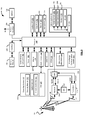
Figure 3 is a block diagram illustrating components of the example electronic device ofFigure 1 in accordance with example aspects of the present disclosure; -
Figure 4 is a flow-chart illustrating an example of a method of preventing observation of password entry on the electronic device ofFigure 1 ; and -
Figure 5 is a flow-chart illustrating another example of a method of preventing observation of password entry on the electronic deviceFigure 1 . - In accordance with an aspect of the present description, described is an electronic device comprising a processor, a display coupled to the processor, a memory coupled to the processor, a camera coupled to the processor, and a security module saved in the memory. The security module configures the processor to activate the camera to acquire an image when the electronic device is in a password entry mode, detect one or more faces present in the image, and present a warning when more than one face is present in the image.
- In accordance with another aspect of the present description, described is a method of preventing observation of password entry on an electronic device having a processor coupled to a camera, a display, and a memory. The method comprises activating the camera to acquire an image when the electronic device is in a password entry mode, detecting one or more faces present in the image, and presenting a warning when more than one face is present in the image.
- In accordance with another aspect of the present description, described is a computer-readable medium storing program instructions that when executed by a processor, cause the processor to perform a method for preventing observation of password entry on an electronic device. The method comprises activating a camera to acquire an image when the electronic device is in a password entry mode, detecting one or more faces present in the image, and presenting a warning when more than one face is present in the image.
- A common problem in the world of security for mobile communication devices is preventing an individual for obtaining a user's password by watching the user input the password into the device. This problem is commonly referred to as "shoulder surfing" when a third party stands behind a user for the purpose of observing the user's input into the mobile communication device.
- To address one or more of the above-noted issues a camera of the mobile communication device, such as a front facing camera, may be activated when the password entry mode of the device is active. The camera system of the device and/or the device processor may have the ability to detect faces in images acquired by the camera. If more than one face is detected in images acquired by the camera when the password entry mode is active, the device may issue an alert or warning to the user of the device, warning that someone may be trying to observe the user enter his or her password.
- Referring first to
Figure 1 , a front view of an exampleelectronic device 201 is illustrated. The electronic device can be a mobile phone, portable computer, smartphone, tablet computer, personal digital assistant, a wearable computer such as a watch, a television, a digital camera or a computer system, for example. The electronic device may be of a form apart from those specifically listed above. -
Figure 1 illustrates a front view of theelectronic device 201. The front view of theelectronic device 201 illustrates afront face 106 of theelectronic device 201. Thefront face 106 of theelectronic device 201 is a side of theelectronic device 201 which includes amain display 204 of theelectronic device 201. Thefront face 106 of theelectronic device 201 is a side of theelectronic device 201 which is configured to be viewed by a user. Thefront face 106 also includes a front facingcamera 253, and optionally aflash 255a. -
Figure 2 illustrates a rear view of theelectronic device 201. The rear view of theelectronic device 201 illustrates arear face 108 of theelectronic device 201. Therear face 108 is a side of theelectronic device 201 that does not include amain display 204 of theelectronic device 201. In the example illustrated, therear face 108 is a side of theelectronic device 201 that is opposite the front face 106 (Figure 1 ) of theelectronic device 201. That is, therear face 108 may be substantially parallel to thefront face 106 of theelectronic device 201. Therear face 108 also includes a rear facingcamera 254, and optionally aflash 255b. - The
electronic device 201 includes one ormore cameras cameras camera camera - In the example illustrated, the
electronic device 201 includes a rear facingcamera 254. A rear facing camera is acamera 254 that is located to obtain images of a subject near arear face 108 of theelectronic device 201. That is, the rear facing camera may be located on or near arear face 108 of theelectronic device 201. - The
electronic device 201 also includes a front facingcamera 253 instead of or in addition to the rear facingcamera 254. The front facingcamera 253 is a camera which is located to obtain images of a subject near thefront face 106 of theelectronic device 201. That is, the front facing camera may be generally located at or near afront face 106 of theelectronic device 201. The front facing camera may be located anywhere on the front surface of the electronic device; for example, the front facing camera may be located above or below thedisplay 204. In at least some examples, thefront facing camera 253 may be provided in a central location relative to thedisplay 204 to facilitate image acquisition of a face. In at least some embodiments, the front facingcamera 253 may be used, for example, to allow a user of theelectronic device 201 to engage in a video-based chat with a user of anotherelectronic device 201. In at least some embodiments, the front facing camera is mounted internally within a housing of theelectronic device 201 beneath a region of thefront face 106 which transmits light. For example, the front facingcamera 253 may be mounted beneath a clear portion of the housing which allows light to be transmitted to the internally mounted camera. - In at least some examples, the
electronic device 201 may include both thefront facing camera 253 and also the rear facingcamera 254. The rear facingcamera 254 may obtain images which are not within the field of view of thefront facing camera 253. The fields of view of the front facing and rear facing cameras may generally be in opposing directions. - The
electronic device 201 includes one ormore flashes flash 255. Theflash 255 may, in at least some examples, be a light emitting diode (LED) flash. Theflash 255 emits electromagnetic radiation. More particularly, theflash 255 may be used to produce a brief bright light which may facilitate picture-taking in low light conditions. That is, theflash 255 may emit light while an image is captured using thecameras flash 255b is located to emit light at therear face 108 of theelectronic device 201. That is, theflash 255b is a rear-facing flash. Theelectronic device 201 may include the front-facingflash 255a instead of or in addition to therear facing flash 255b to emit light at thefront face 106 of theelectronic device 201. Theelectronic device 201 may have additional camera hardware which may complement thecameras - Still referring to
Figure 2 ,transparent covers 280 cover the image sensors of thecameras flash 255. Thetransparent cover 280 allows light to pass through (e.g. from theflash 255 to the exterior of the housing or from the exterior of the housing to the image sensor) and prevents debris or dirt from entering into the housing. Dirt or debris that could otherwise enter into the housing could potentially damage the components of thecamera flash 255. In the example illustrated inFigure 2 transparent covers 280 are secured to the housing. For example, thetransparent covers 280 may be secured to the housing using an adhesive or using snaps or similar attachment mechanism in such a manner so as to be flush with the housing. The transparent covers 280 can be transparent and made out of glass or plastic or another suitable transparent or translucent material. For example, thecover 280 can be made out of stained or partially stained glass. - Referring now to
Figure 3 , a block diagram of an exampleelectronic device 201 is illustrated. Theelectronic device 201 ofFigure 3 may include a housing which houses components of theelectronic device 201. Internal components of theelectronic device 201 may be constructed on a printed circuit board (PCB). Theelectronic device 201 includes a controller including at least one processor 240 (such as a microprocessor) which controls the overall operation of theelectronic device 201. Theprocessor 240 interacts with components or device subsystems such as awireless communication subsystem 211 for exchanging radio frequency signals with awireless network 101 to perform communication functions. Theprocessor 240 interacts with additional device subsystems including one or more input interfaces 206 (such as a keyboard, one or more control buttons, one ormore microphones 258, one ormore cameras flash memory 244, random access memory (RAM) 246, read only memory (ROM) 248, auxiliary input/output (I/O)subsystems 250, a data port 252 (which may be a serial data port, such as a Universal Serial Bus (USB) data port), one or more output interfaces 205 (such as a display 204 (which may be a liquid crystal display (LCD)), aflash 255, one ormore speakers 256, or other output interfaces), a shortrange communication module 262, and other device subsystems generally designated as 264. Some of the components or subsystems shown inFigure 3 perform communication-related functions, whereas other components or subsystems may provide "resident" or on-device functions. - The
electronic device 201 may include a touchscreen display. The touchscreen display may be constructed using a touch-sensitive input surface connected to an electronic controller. The touch-sensitive input surface overlays thedisplay 204 and may be referred to as a touch-sensitive overlay. The touch-sensitive overlay and the electronic controller provide a touch-sensitive input interface 206 and theprocessor 240 interacts with the touch-sensitive overlay via the electronic controller. That is, the touchscreen display acts as both aninput interface 206 and anoutput interface 205. - The
communication subsystem 211 includes areceiver 214, atransmitter 216, and associated components, such as one ormore antenna elements antenna elements electronic device 201 and a single antenna may be shared by bothreceiver 214 andtransmitter 216. The particular design of thewireless communication subsystem 211 depends on thewireless network 101 in which theelectronic device 201 is intended to operate. - The
electronic device 201 may communicate with any one of a plurality of fixed transceiver base stations of thewireless network 101 within its geographic coverage area. Theelectronic device 201 may send and receive communication signals over thewireless network 101 after the required network registration or activation procedures have been completed. Signals received by theantenna 218 through thewireless network 101 are input to thereceiver 214, which may perform such common receiver functions as signal amplification, frequency down conversion, filtering, channel selection, etc., as well as analog-to-digital (A/D) conversion. A/D conversion of a received signal allows more complex communication functions such as demodulation and decoding to be performed in theDSP 215. In a similar manner, signals to be transmitted are processed, including modulation and encoding, for example, by theDSP 215. These DSP-processed signals are input to thetransmitter 216 for digital-to-analog (D/A) conversion, frequency up conversion, filtering, amplification, and transmission to thewireless network 101 via theantenna 221. The DSP215 not only processes communication signals, but may also provide for receiver and transmitter control. For example, the gains applied to communication signals in thereceiver 214 and thetransmitter 216 may be adaptively controlled through automatic gain control algorithms implemented in theDSP 215. - In some examples, the auxiliary input/output (I/O)
subsystems 250 may include an external communication link or interface, for example, an Ethernet connection. Theelectronic device 201 may include other wireless communication interfaces for communicating with other types of wireless networks; for example, a wireless network such as an orthogonal frequency division multiplexed (OFDM) network. - In some example embodiments, the
electronic device 201 also includes a removable memory module 230 (typically including flash memory) and amemory module interface 232. Network access may be associated with a subscriber or user of theelectronic device 201 via thememory module 230, which may be a Subscriber Identity Module (SIM) card for use in a GSM network or other type of memory module for use in the relevant wireless network type. Thememory module 230 may be inserted in or connected to thememory module interface 232 of theelectronic device 201. - The
electronic device 201 may storedata 227 in an erasable persistent memory, which in one example embodiment is theflash memory 244. In various examples, thedata 227 may include service data having information used by theelectronic device 201 to establish and maintain communication with thewireless network 101. Thedata 227 may also include user application data such as email messages, address book and contact information, calendar and schedule information, notepad documents, images, and other commonly stored user information stored on theelectronic device 201 by its user, and other data. Thedata 227 may, in at least some examples, include metadata which may store information about the images. In some embodiments the metadata and the images may be stored together. That is, a single file may include both an image and also metadata regarding that image. For example, in at least some embodiments, the image may be formatted and stored as a JPEG image. - The
data 227 stored in the persistent memory (e.g. flash memory 244) of theelectronic device 201 may be organized, at least partially, into a number of databases or data stores each containing data items of the same data type or associated with the same application. For example, email messages, contact records, and task items may be stored in individual databases within theelectronic device 201 memory. - The
data port 252 may be used for synchronization with a user's host computer system. Thedata port 252 enables a user to set preferences through an external device or software application and extends the capabilities of theelectronic device 201 by providing for information or software downloads to theelectronic device 201 other than through thewireless network 101. The alternate download path may for example, be used to load an encryption key onto theelectronic device 201 through a direct, reliable and trusted connection to thereby provide secure device communication. - In some examples, the
electronic device 201 is provided with a service routing application programming interface (API) which provides an application with the ability to route traffic through a serial data (i.e., USB) or Bluetooth® (Bluetooth® is a registered trademark of Bluetooth SIG, Inc.) connection to the host computer system using standard connectivity protocols. When a user connects theirelectronic device 201 to the host computer system via a USB cable or Bluetooth® connection, traffic that was destined for thewireless network 101 is automatically routed to theelectronic device 201 using the USB cable or Bluetooth® connection. Similarly, any traffic destined for thewireless network 101 is automatically sent over the USB cable Bluetooth® connection to the host computer for processing. Further, data may be transmitted to and from theelectronic device 201 using a WiFi network or using near field communication technologies. - The
electronic device 201 also includes abattery 238 as a power source, which is typically one or more rechargeable batteries that may be charged, for example, through charging circuitry coupled to abattery interface 236 such as theserial data port 252. Thebattery 238 provides electrical power to at least some of the electrical circuitry in theelectronic device 201, and thebattery interface 236 provides a mechanical and electrical connection for thebattery 238. Thebattery interface 236 is coupled to a regulator (not shown) which provides power V+ to the circuitry of theelectronic device 201. - The short
range communication module 262 provides for communication between theelectronic device 201 and different systems or devices, which need not necessarily be similar devices. For example, the shortrange communication module 262 may include an infrared device and associated circuits and components, or a wireless bus protocol compliant communication mechanism such as a Bluetooth® communication module to provide for communication with similarly-enabled systems and devices. - The
electronic device 201 can also include one ormore sensors 301 such as temperature sensor, rotation sensors (for example, a gyroscope), translation sensors (for example accelerometers), position sensors (for example, magnetometers), and sensor sub-systems such as ageolocalization sub-system 302, which can be based on a global positional signal. - In the example illustrated, the
cameras camera system 260 along with aflash 255, an optical image stabilizer (OIS) 298 and an image signal processor (ISP) 294. The optical image stabilizer (OIS) 298 may be integrated with thecameras OIS 298 may be considered as a functional part of thecamera system 260. Similarly, theISP 294 may be embedded in theprocessor 240 and it may also be considered as a functional part of thecamera system 260. In at least some examples, thecameras image signal processor 294 which may provide at least some camera-related functions, with theimage signal processor 294 being either embedded in thecameras image signal processor 294 may be configured to provide auto-focusing functions. Functions or features which are described below with reference to thecamera application 297 may, in at least some embodiments, be provided, in whole or in part, by theimage signal processor 294. - The
camera system 260 associated with theelectronic device 201 also includes aflash 255. As noted above, theflash 255 is used to illuminate a subject while thecameras flash 255 may, for example, be used in low light conditions. In the example illustrated, theflash 255 is coupled with themain processor 240 of theelectronic device 201. Theflash 255 may be coupled to theimage signal processor 294, which may be used to trigger theflash 255. Theimage signal processor 294 may, in at least some embodiments, control theflash 255. In at least some such embodiments, applications associated with themain processor 240 may be permitted to trigger theflash 255 by providing an instruction to theimage signal processor 294 to instruct theimage signal processor 294 to trigger theflash 255. In one or more embodiments, theimage signal processor 294 may be coupled to theprocessor 240. - The
optical image stabilizer 298 can be coupled to thecamera 253 or theimage signal processor 294 or both and operates to stabilize thecamera 253 during an image capture. Theoptical image stabilizer 298 may receive instructions from theimage signal processor 294. Similarly, theoptical image stabilizer 298 may be coupled to theprocessor 240 and may receive instructions from theprocessor 240. Theimage signal processor 294 may obtain data from theoptical image stabilizer 298 relating to its movement and operation. In one or more embodiments, thecamera system 260 may have a separate memory (not shown) on which theimage signal processor 294 can store data and retrieve instructions. Such instructions may, for example, have been stored in the memory by theprocessor 240, which may in some embodiments also be coupled to the separate memory in thecamera system 260. - A predetermined set of applications that control basic device operations, including data and possibly voice communication applications may be installed on the
electronic device 201 during or after manufacture. Additional applications and/or upgrades to anoperating system 222 orsoftware applications 224 may also be loaded onto theelectronic device 201 through thewireless network 101, the auxiliary I/O subsystem 250, thedata port 252, the shortrange communication module 262, or othersuitable device subsystems 264. The downloaded programs or code modules may be permanently installed; for example, written into the program memory (e.g. the flash memory 244), or written into and executed from theRAM 246 for execution by theprocessor 240 at runtime. - The electronic device may have a
security module 299, which may be implemented as part of theoperating system 222. Alternatively, thesecurity module 299 may be installed as one of theapplications 224. Thesecurity module 299 may implement many or all of the security features of theelectronic device 201, such as password entry, voice detection, face detection and/or face recognition, data encryption, etc. Thesecurity module 299 may operate in communication with other applications or module, such as thecamera application 297, for receiving data from one or both of thecameras - In some example embodiments, the
electronic device 201 may provide two principal modes of communication: a data communication mode and a voice communication mode. In the data communication mode, a received data signal such as a text message, an email message, or webpage download will be processed by thecommunication subsystem 211 and input to theprocessor 240 for further processing. For example, a downloaded webpage may be further processed by a web browser or an email message may be processed by the email messaging application and output to thedisplay 204. A user of theelectronic device 201 may also compose data items, such as email messages; for example, using aninput interface 206 in conjunction with thedisplay 204. These composed items may be transmitted through thecommunication subsystem 211 over thewireless network 101. - In the voice communication mode, the
electronic device 201 provides telephony functions and may operate as a typical cellular phone. The overall operation is similar to the data communication mode, except that the received signals would be output to thespeaker 256 and signals for transmission would be generated by a transducer such as themicrophone 258. The telephony functions are provided by a combination of software/firmware (i.e., a voice communication module) and hardware (i.e., themicrophone 258, thespeaker 256 and input devices). Alternative voice or audio I/O subsystems, such as a voice message recording subsystem, may also be implemented on theelectronic device 201. Although voice or audio signal output may be accomplished primarily through thespeaker 256, thedisplay 204 may also be used to provide an indication of the identity of a calling party, duration of a voice call, or other voice call related information. - The
processor 240 operates under stored program control and executessoftware modules 220, such asapplications 224, stored in memory such as persistent memory; for example, in theflash memory 244. As illustrated inFigure 3 , thesoftware modules 220 may include theoperating system software 222 and one or moreadditional applications 224 or modules such as, for example, thecamera application 297. Theprocessor 240 may also operate to processdata 227 stored in memory associated with theelectronic device 201. - In the example of
Figure 3 , thecamera application 297 is illustrated as being implemented as a stand-alone application 224. However, in other example examples, thecamera application 297 could be provided by another application or module such as, for example, theoperating system software 222 or, in some examples, thesecurity module 299. Further, while thecamera application 297 is illustrated with a single block, the functions or features provided by thecamera application 297 could, in at least some embodiments, be divided up and implemented by a plurality of applications and/or modules. In one or more embodiments, thecamera application 297 can be implemented by theISP 294. - The
camera application 297 may, for example, be configured to provide a viewfinder on thedisplay 204 by displaying, in real time or near real time, an image defined in the electronic signals received from thecameras camera application 297 may also be configured to capture an image or video by storing an image or video defined by the electronic signals received from thecameras image signal processor 294. For example, thecamera application 297 may be configured to store an image or video to memory of theelectronic device 201. - The
camera application 297 may also be configured to control options or preferences associated with thecameras camera application 297 may be configured to control a camera lens aperture and/or a shutter speed. The control of such features may, in at least some embodiments, be automatically performed by theimage signal processor 294 associated with thecameras - In at least some examples, the
camera application 297 may be configured to focus thecameras camera application 297 may be configured to request theimage signal processor 294 to control an actuator of thecameras cameras cameras cameras 253, 254 (e.g. subject at macro position, such as a person entering a password), theimage signal processor 294 may control the actuator to cause the actuator to move the lens away from the image sensor. - In at least some examples, the
image signal processor 294 may provide for auto-focusing capabilities. For example, theimage signal processor 294 may analyze received electronic signals to determine whether the images captured by the camera are in focus. That is, theimage signal processor 294 may determine whether the images defined by electronic signals received from thecameras image signal processor 294 may, for example, make this determination based on the sharpness of such images. If theimage signal processor 294 determines that the images are not in focus, then thecamera application 297 may cause theimage signal processor 294 to adjust the actuator which controls the lens to focus the image. - In at least some examples, the
camera application 297 may be configured to control a flash associated with thecameras cameras camera application 297 is configured to provide digital zoom features. Thecamera application 297 may provide digital zoom features by cropping an image down to a centered area with the same aspect ratio as the original. In at least some embodiments, thecamera application 297 may interpolate within the cropped image to bring the cropped image back up to the pixel dimensions of the original. - The
software modules 220 or parts thereof may be temporarily loaded into volatile memory such asRAM 246. TheRAM 246 is used for storing runtime data variables and other types of data or information. Although specific functions are described for various types of memory, this is merely one example, and a different assignment of functions to types of memory - Referring to
Figure 4 , anexemplary method 400 of preventing observation of password entry on an electronic device will now be described. In one example, themethod 400 can be implemented on anelectronic device 201 having aprocessor 240, adisplay 204 coupled to theprocessor 240, a memory (244 and/or 246 and/or 248) coupled to theprocessor 240, and a camera (e.g.,camera system 260 having thecameras 253 and/or 254) coupled to theprocessor 240. - At 402, a password entry mode is initiated on the
electronic device 201. The password entry mode may be initiated in response to a user of theelectronic device 201 attempting to use theelectronic device 201 when theelectronic device 201 is in a locked mode. For example, when theelectronic device 201 is in a locked mode requiring password entry for further use, the user may attempt to provide an input to theelectronic device 201, such as by touching thedisplay 204 that provides aninput 205 to theprocessor 240, by pushing a button on theelectronic device 201 that provides aninput 205 to theprocessor 240, or even by picking up theelectronic device 204 that may provide an input to theprocessor 240, such as from thesensor 301. When the user attempts to provide such input to theelectronic device 201 when in a locked mode, thesecurity module 299 may require password entry from the user before providing some or any of the functions of theelectronic device 201. In one example, the required password entry may be provided on thedisplay 204 in the form of a prompt or password entry field where the user may touch keys of a virtual keyboard displayed on thedisplay 204 in order to enter the password needed to unlock the device. - When the password entry mode described above is active (e.g., before the user has entered the entire correct password and pressed the enter key, resulting in verification of the password and termination of the locked mode of the electronic device 201), a camera may be activated at 404. The camera may be activated to acquire an image when the
electronic device 201 is in the password entry mode. In one example, the camera may be a front facing camera such as thefront facing camera 253, since the user entering the password will typically be located in front of thefront face 106 of thewireless device 201. While thefront facing camera 253 is used as an example, any camera such as thecamera 254 or both of thecameras camera 253 and the data is provided to theISP 294 and/or to theprocessor 240. - At 406, the data representing the image is processed to detect faces (e.g., by either the
ISP 294 or the processor 240). Face detection may be performed according to any known or yet to be designed face detection methodology. Exemplary face detection methodologies are already employed on existing digital cameras and portable electronic devices, as illustrated when squares, crosshairs, or other indicia are shown on camera viewfinders indicating the presence of one or more faces in an image to be acquired. At 406, any faces present in the data representing the image may be detected and the resulting number of detected faces counted with the result assigned to a variable (e.g., X faces are present in the current image). - At 408, a query is executed to see if X> 1. If X=< 1, the
method 400 returns to 404, where the sequence ofblocks method 400 terminates when the password entry mode terminates or more than one face is detected, in which case themethod 400 proceeds to 410. - If, at 408, X> 1, the
method 400 proceeds to 410, where a warning is presented if more than one face is present in the image. The warning may include a visual notification displayed on thedisplay 204. The visual notification may include a colour indication displayed on thedisplay 204 adjacent to a password entry area displayed on thedisplay 204 and/or a pop-up window having a message displayed on thedisplay 204. In one example, the colour indication could be in the form of a coloured border placed around the password entry field or password entry window present on thedisplay 204. In another example, the colour indication displayed on thedisplay 204 could be a background colour change applied to thedisplay 204 such that most of or the entire colour of thedisplay 204 changes. In another example, a pop-up window may be displayed on thedisplay 204 with a message telling the user that more than one person or face has been detected. In another example, the message may simply instruct the user to ensure that no one is observing the device password being entered. While a number of examples of visual notifications have been provided, any visual notification, whether discrete or overt, could be used to alert the user that more than one person or face has been detected by thefront facing camera 253, according to the design criteria of a particular application. - In another example, the
electronic device 201 has a speaker such as thespeaker 256 coupled to theprocessor 240 and the warning may include an audio notification played through the speaker. In one example, the user may have headphones connected to theelectronic device 201 and the device may play a simple message to the user of theelectronic device 201. The message may read content to the user that is similar to the message contained in the pop-up windows, discussed above, or the message may be any suitable tone, noise, pre-recorded message, etc. - In another example, the
electronic device 201 has a vibrator (e.g.,other device subsystems 264 may include a vibrator) coupled to theprocessor 240 and the warning may include a vibratory notification presented using the vibrator. For example, if the user is holding theelectronic device 201 in a password entry mode and thefront facing camera 253 detects more than one person or face in an image, theelectronic device 201 may vibrate briefly to alert the user that the entry of the password could be observed by another person. - Once a warning is presented on the
display 204 atblock 410, themethod 400 then returns to theblock 404. Optionally, at 410, password entry mode of theelectronic device 201 may be disabled when more than one face is detected in the image. For example, the warning may be displayed at 410 and any password entered by a user may be rejected as long as more than one face is detected in the image. In another example, the user may be prevented from entering any further password characters as long as more than one face is detected in the image. - Referring now to
Figure 5 , anotherexemplary method 500 of preventing observation of password entry on an electronic device will now be described.Blocks method 500 are similar toblocks method 400, respectively, and therefore the description ofblocks - In one example, the
method 500 can be implemented on anelectronic device 201 having aprocessor 240, adisplay 204 coupled to theprocessor 240, a memory (244 and/or 246 and/or 248) coupled to theprocessor 240, and a camera (e.g.,camera system 260 having thecameras 253 and/or 254) coupled to theprocessor 240. - At 502, a password entry mode is initiated on the
electronic device 201, as described above with reference to block 402. - When the password entry mode described above is active (e.g., before the user has entered the entire correct password and pressed the enter key, resulting in verification of the password and termination of the locked mode of the electronic device 201), a camera may be activated at 504, as described above with reference to block 404.
- At 506, the data presenting the image is processed to detect faces (e.g., by either the
ISP 294 or the processor 240), as described above with reference to block 406. At 506, any faces present in the data representing the image may be detected and the resulting number counted with the result assigned to a variable (e.g., Y faces are present in the current image). - At 508, a query is executed to see if Y> 1.
Block 508 may also apply face recognition. Under control of thesecurity module 299, theelectronic device 201 may have a previously stored sample of the owner's face in memory (e.g., asdata 227 stored in the memory 244). Whenever a face is detected at theblock 506, theblock 508 may also attempt facial recognition to see if the detected face is that of the owner of theelectronic device 201. If Y< = 1 and the detected face is that of the owner, themethod 500 returns to 504, where the sequence ofblocks method 500 terminates when the password entry mode terminates or more than one face is detected, in which case themethod 500 proceeds to 510. - If, at 508, Y> 1 and/or Y<= 1 and any face is detected that is not that of the owner of the
wireless device 201, themethod 500 proceeds to 510, where a warning is presented if more than one face is present in the image or if any face that is not that of the owner of thewireless device 201 is detected in the image. - The warning may include a visual notification displayed on the
display 204. The visual notification may include a colour indication displayed on thedisplay 204 adjacent to a password entry area displayed on thedisplay 204 and/or a pop-up window having a message displayed on thedisplay 204. In one example, the colour indication could be in the form of a coloured border placed around the password entry field or password entry window present on thedisplay 204. In another example, the colour indication displayed on thedisplay 204 could be a background colour change applied to thedisplay 204 such that most of or the entire colour of thedisplay 204 changes. In another example, a pop-up window may be displayed on thedisplay 204 with a message telling the user that more than one person or face has been detected, or telling the user that he is not authorized to enter a password into thewireless device 201 if the user is not the owner of thewireless device 201. In another example, the message may simply instruct the user to ensure that no one is observing the device password being entered. While a number of examples of visual notifications have been provided, any visual notification, whether discrete or overt, could be used to alert the user that more than one person or face has been detected by thefront facing camera 253, according to the design criteria of a particular application. - In another example, an audio notification or vibratory notification may be presented, as previously described.
- Once a warning is presented on the
display 204, themethod 500 then returns to theblock 504. Optionally, at 510, password entry mode of theelectronic device 201 may be disabled when more than one face is detected in the image or when any face not belonging to the owner of theelectronic device 201 is present in the image. For example, the warning may be displayed at 510 and any password entered by a user may be rejected as long as more than one face is detected in the image or when any face not belonging to the owner of theelectronic device 201 is present in the image. In another example, the user may be prevented from entering any further password characters as long as more than one face is detected in the image or when any face not belonging to the owner of theelectronic device 201 is present in the image. - While the present application mentions cameras for determining whether more than one face can be detected in front of the electronic device, any suitable sensor of the electronic device may be used to gather data to determine whether more than one person is likely in a position to observe the display of the electronic device.
- While the present application is primarily described in terms of methods, a person of ordinary skill in the art will understand that the present application is also directed to various apparatus' such as an electronic device including a mobile communications device or camera. The electronic device includes components for performing at least some of the aspects and features of the described methods, which may be by way of hardware components (such as the
memory 244 and/or the processor 240), software or any combination of the two, or in any other manner. Moreover, an article of manufacture for use with the apparatus, such as a pre-recorded storage device or other similar computer readable storage medium including program instructions recorded thereon, or a computer data signal carrying computer readable program instructions may direct an apparatus to facilitate the practice of the described methods. For example, a computer readable storage medium may include computer executable instructions tangibly embodying code for performing one or more of the methods described herein. It is understood that such apparatus and articles of manufacture also come within the scope of the present application. - The term "computer readable medium" or "computer readable storage medium" as used herein means any medium which can store instructions for use by or execution by a computer or other computing device including but not limited to, a portable computer diskette, a hard disk drive (HDD), a random access memory
- (RAM), a read-only memory (ROM), an erasable programmable-read-only memory (EPROM) or flash memory, an optical disc such as a Compact Disc (CD), Digital Versatile Disc (DVD) or Blu-ray™ Disc, and a solid state storage device (e.g., NAND flash or synchronous dynamic RAM (SDRAM)).
- One or more embodiments have been described by way of example. It will be apparent to persons skilled in the art that a number of variations and modifications can be made without departing from the scope of what is defined in the claims.
Claims (15)
- An electronic device comprising:a processor;a display coupled to the processor;a memory coupled to the processor;a camera coupled to the processor; anda security module saved in the memory, the security module for configuring the processor to:activate the camera to acquire an image when the electronic device is in a password entry mode;detect one or more faces in the image; andpresent a warning when more than one face is detected in the image.
- The electronic device according to claim 1, wherein the camera includes a front facing camera.
- The electronic device according to claim 1 or 2, wherein the warning includes a visual notification displayed on the display.
- The electronic device according to claim 3, wherein the visual notification includes at least one of a colour indication displayed on the display adjacent to a password entry area displayed on the display, and a pop-up window having a message displayed on the display.
- The electronic device according to any preceding claim, wherein the electronic device further has at least one of:a speaker coupled to the processor and the warning includes an audio notification played through the speaker;a vibrator coupled to the processor and the warning includes a vibratory notification presented using the vibrator.
- The electronic device according to any preceding claim, wherein the security module further configures the processor to attempt to recognize each of the one or more faces present in the image as either an authorized user of the electronic device or someone else; and at least one of:disable the password entry mode when any face other than a face of the authorized user of the electronic device is present in the image,present a warning when any face other than a face of the authorized user of the electronic device is present in the image.
- The electronic device according to any preceding claim, wherein the security module further configures the processor to disable the password entry mode when no faces are present in the image.
- A method of preventing observation of password entry on an electronic device having a processor coupled to a camera, a display, and a memory, the method comprising:activating the camera to acquire an image when the electronic device is in a password entry mode;detecting one or more faces present in the image; andpresenting a warning when more than one face is detected in the image.
- The method according to claim 8, wherein the camera includes a front facing camera on the electronic device.
- The method according to claim 8 or 9, wherein presenting the warning when more than one face is present in the image includes presenting a visual notification on the display.
- The method according to claim 10, wherein the visual notification includes at least one of a colour indication displayed on the display adjacent to a password entry area displayed on the display, and a pop-up window having a message displayed on the display.
- The method according to any one of claims 8 to 10, wherein the electronic device further has at least one of:a speaker coupled to the processor and presenting the warning when more than one face is present in the image includes playing an audio notification through the speaker;a vibrator coupled to the processor and presenting the warning when more than one face is present in the image includes activating the vibrator.
- The method according to any one of claims 8 to 12, the method further comprising attempting to recognize the one or more faces present in the image as either an authorized user of the electronic device or someone else; and at least one of:disabling the password entry mode when any face other than a face of the authorized user of the electronic device is present in the image;presenting a warning when any face other than a face of the authorized user of the electronic device is present in the image.
- The method according to any one of claims 8 to 13, the method further comprising displaying a warning when no faces are present in the image.
- A computer-readable medium storing program instructions that when executed by a processor, cause the processor to perform the method of any one of claims 8 to 14.
Applications Claiming Priority (1)
| Application Number | Priority Date | Filing Date | Title |
|---|---|---|---|
| US14/245,478 US9495520B2 (en) | 2014-04-04 | 2014-04-04 | System and method for preventing observation of password entry using face detection |
Publications (2)
| Publication Number | Publication Date |
|---|---|
| EP2927835A1 true EP2927835A1 (en) | 2015-10-07 |
| EP2927835B1 EP2927835B1 (en) | 2022-05-04 |
Family
ID=52692410
Family Applications (1)
| Application Number | Title | Priority Date | Filing Date |
|---|---|---|---|
| EP15158082.6A Active EP2927835B1 (en) | 2014-04-04 | 2015-03-06 | System and method for preventing observation of password entry using face detection |
Country Status (2)
| Country | Link |
|---|---|
| US (1) | US9495520B2 (en) |
| EP (1) | EP2927835B1 (en) |
Cited By (2)
| Publication number | Priority date | Publication date | Assignee | Title |
|---|---|---|---|---|
| EP3416079A1 (en) * | 2017-06-16 | 2018-12-19 | Connexcom Ag | Computer-implemented method and computer program product for controlling access to a terminal |
| US11748508B2 (en) | 2017-11-16 | 2023-09-05 | Huawei Technologies Co., Ltd. | Display method and apparatus, and terminal |
Families Citing this family (4)
| Publication number | Priority date | Publication date | Assignee | Title |
|---|---|---|---|---|
| CN107733858A (en) * | 2017-09-01 | 2018-02-23 | 北京知道未来信息技术有限公司 | A kind of monitoring device and method of intelligent protection camera information |
| US10909225B2 (en) * | 2018-09-17 | 2021-02-02 | Motorola Mobility Llc | Electronic devices and corresponding methods for precluding entry of authentication codes in multi-person environments |
| KR102764266B1 (en) * | 2019-06-17 | 2025-02-07 | 현대자동차주식회사 | User interface system and method in vehicle |
| US12093410B1 (en) | 2020-12-07 | 2024-09-17 | United Services Automobile Association (Usaa) | Confidential information tracking system |
Citations (4)
| Publication number | Priority date | Publication date | Assignee | Title |
|---|---|---|---|---|
| JP2006039841A (en) * | 2004-07-26 | 2006-02-09 | Nec Corp | Processing device preventing spying through face detection, processing system, automatic teller, processing method, and program |
| US20070150827A1 (en) * | 2005-12-22 | 2007-06-28 | Mona Singh | Methods, systems, and computer program products for protecting information on a user interface based on a viewability of the information |
| US20120235790A1 (en) * | 2011-03-16 | 2012-09-20 | Apple Inc. | Locking and unlocking a mobile device using facial recognition |
| US20140029810A1 (en) * | 2012-07-25 | 2014-01-30 | John Mathias Barr | Securing information using entity detection |
Family Cites Families (22)
| Publication number | Priority date | Publication date | Assignee | Title |
|---|---|---|---|---|
| US20070128899A1 (en) * | 2003-01-12 | 2007-06-07 | Yaron Mayer | System and method for improving the efficiency, comfort, and/or reliability in Operating Systems, such as for example Windows |
| JP2005100084A (en) * | 2003-09-25 | 2005-04-14 | Toshiba Corp | Image processing apparatus and method |
| JP2005244347A (en) * | 2004-02-24 | 2005-09-08 | Toshiba Corp | Digital camera |
| JP2006259930A (en) * | 2005-03-15 | 2006-09-28 | Omron Corp | Display device, control method therefor, electronic device including display device, display device control program, and recording medium recording the program |
| US8102985B2 (en) * | 2005-11-11 | 2012-01-24 | Cisco Technology, Inc. | Method and system for providing a camp-on hold service |
| US8188883B2 (en) * | 2006-09-28 | 2012-05-29 | Landis+Gyr, Inc. | Utility meter with communication system displays |
| DE102007006847A1 (en) * | 2007-02-12 | 2008-08-14 | Voice Trust Ag | Digital method and arrangement for authentication of a user of a telecommunications or data network |
| US7956727B2 (en) * | 2007-03-22 | 2011-06-07 | Carespeak Communications, Inc. | Methods and systems for medication management |
| US8600120B2 (en) | 2008-01-03 | 2013-12-03 | Apple Inc. | Personal computing device control using face detection and recognition |
| US8941466B2 (en) * | 2009-01-05 | 2015-01-27 | Polytechnic Institute Of New York University | User authentication for devices with touch sensitive elements, such as touch sensitive display screens |
| US8287055B2 (en) * | 2010-09-28 | 2012-10-16 | Robert Bosch Gmbh | Brake control of a vehicle based on driver behavior |
| US8550903B2 (en) * | 2010-11-15 | 2013-10-08 | Bally Gaming, Inc. | System and method for bonus gaming using a mobile device |
| US20130006848A1 (en) * | 2010-11-12 | 2013-01-03 | Kuttuva Avinash | Method of virtual transaction using mobile electronic devices or fixed electronic devices or a combination of both, for global commercial or noncommercial purposes |
| KR20120080376A (en) * | 2011-01-07 | 2012-07-17 | 삼성전자주식회사 | Digital image photographing apparatus and method for controlling the same |
| US8726366B2 (en) * | 2011-03-30 | 2014-05-13 | Elwha Llc | Ascertaining presentation format based on device primary control determination |
| US7991388B1 (en) * | 2011-05-10 | 2011-08-02 | CommerceTel, Inc. | Geo-bio-metric PIN |
| WO2013039961A2 (en) * | 2011-09-12 | 2013-03-21 | Get HookD LLC | Aggregating check-in social networking system and method |
| CN103324899A (en) * | 2012-03-23 | 2013-09-25 | 富泰华工业(深圳)有限公司 | Electronic equipment and display screen peeping-prevention method thereof |
| US8600110B1 (en) * | 2012-09-17 | 2013-12-03 | Elwha Llc | Unauthorized viewer detection system and method |
| KR102092571B1 (en) * | 2013-01-04 | 2020-04-14 | 삼성전자 주식회사 | Apparatus and method for taking a picture of portrait portable terminal having a camera and camera device |
| US9432366B2 (en) * | 2013-04-01 | 2016-08-30 | AMI Research & Development, LLC | Fingerprint based smartphone user verification |
| US9400878B2 (en) * | 2013-11-08 | 2016-07-26 | Dell Products L.P. | Context analysis at an information handling system to manage authentication cycles |
-
2014
- 2014-04-04 US US14/245,478 patent/US9495520B2/en active Active
-
2015
- 2015-03-06 EP EP15158082.6A patent/EP2927835B1/en active Active
Patent Citations (4)
| Publication number | Priority date | Publication date | Assignee | Title |
|---|---|---|---|---|
| JP2006039841A (en) * | 2004-07-26 | 2006-02-09 | Nec Corp | Processing device preventing spying through face detection, processing system, automatic teller, processing method, and program |
| US20070150827A1 (en) * | 2005-12-22 | 2007-06-28 | Mona Singh | Methods, systems, and computer program products for protecting information on a user interface based on a viewability of the information |
| US20120235790A1 (en) * | 2011-03-16 | 2012-09-20 | Apple Inc. | Locking and unlocking a mobile device using facial recognition |
| US20140029810A1 (en) * | 2012-07-25 | 2014-01-30 | John Mathias Barr | Securing information using entity detection |
Cited By (4)
| Publication number | Priority date | Publication date | Assignee | Title |
|---|---|---|---|---|
| EP3416079A1 (en) * | 2017-06-16 | 2018-12-19 | Connexcom Ag | Computer-implemented method and computer program product for controlling access to a terminal |
| WO2018229246A1 (en) * | 2017-06-16 | 2018-12-20 | Connexcom Ag | Computer-implemented method and computer program product for the access control of a terminal |
| US12602493B2 (en) | 2017-06-16 | 2026-04-14 | Pp Corporate Ag | Computer-implemented method and computer program product for the access control of a terminal |
| US11748508B2 (en) | 2017-11-16 | 2023-09-05 | Huawei Technologies Co., Ltd. | Display method and apparatus, and terminal |
Also Published As
| Publication number | Publication date |
|---|---|
| US9495520B2 (en) | 2016-11-15 |
| US20150286804A1 (en) | 2015-10-08 |
| EP2927835B1 (en) | 2022-05-04 |
Similar Documents
| Publication | Publication Date | Title |
|---|---|---|
| EP2927903B1 (en) | System and method for electronic device display privacy | |
| US10003730B2 (en) | Method and device for sharing a camera feature | |
| EP2927835B1 (en) | System and method for preventing observation of password entry using face detection | |
| US10292004B2 (en) | Method, device and medium for acquiring location information | |
| EP3099063A1 (en) | Video communication method and apparatus | |
| US9800666B2 (en) | Method and client terminal for remote assistance | |
| EP3179711B1 (en) | Method and apparatus for preventing photograph from being shielded | |
| US10425403B2 (en) | Method and device for accessing smart camera | |
| US20170034409A1 (en) | Method, device, and computer-readable medium for image photographing | |
| EP3200116B1 (en) | Method and apparatus for acquiring information via a virtual identity module from lost or stolen terminal | |
| EP3246886A1 (en) | Alarm method and device, control device and sensing device | |
| EP3179397A1 (en) | Methods and devices for managing automatic parallel login and logout in several applications | |
| US20170031540A1 (en) | Method and device for application interaction | |
| EP3435349B1 (en) | Method and apparatus for processing network failure | |
| EP3113071A1 (en) | Method and device for acquiring iris image | |
| EP3147802B1 (en) | Method and apparatus for processing information | |
| US20230037475A1 (en) | Network connection method and device and readable storage medium | |
| CA2802293C (en) | Method and device for sharing a camera feature | |
| CN104284093A (en) | Panorama shooting method and device | |
| US20130235233A1 (en) | Methods and devices for capturing images | |
| US20200106936A1 (en) | Full screen terminal, operation control method, and device based on full screen terminal | |
| CN105100749A (en) | Image pick-up method and device as well as terminal | |
| EP2637397A1 (en) | Methods and devices for capturing images | |
| CN112134992B (en) | Terminal device and control method thereof | |
| CN116339498A (en) | User information acquisition method and device, electronic equipment and storage medium |
Legal Events
| Date | Code | Title | Description |
|---|---|---|---|
| PUAI | Public reference made under article 153(3) epc to a published international application that has entered the european phase |
Free format text: ORIGINAL CODE: 0009012 |
|
| 17P | Request for examination filed |
Effective date: 20150306 |
|
| AK | Designated contracting states |
Kind code of ref document: A1 Designated state(s): AL AT BE BG CH CY CZ DE DK EE ES FI FR GB GR HR HU IE IS IT LI LT LU LV MC MK MT NL NO PL PT RO RS SE SI SK SM TR |
|
| AX | Request for extension of the european patent |
Extension state: BA ME |
|
| RIC1 | Information provided on ipc code assigned before grant |
Ipc: H04L 29/06 20060101ALI20170329BHEP Ipc: G06F 21/00 20130101AFI20170329BHEP Ipc: H04W 12/12 20090101ALI20170329BHEP Ipc: H04W 12/06 20090101ALI20170329BHEP Ipc: G06F 21/32 20130101ALI20170329BHEP |
|
| STAA | Information on the status of an ep patent application or granted ep patent |
Free format text: STATUS: EXAMINATION IS IN PROGRESS |
|
| 17Q | First examination report despatched |
Effective date: 20170511 |
|
| RAP1 | Party data changed (applicant data changed or rights of an application transferred) |
Owner name: BLACKBERRY LIMITED |
|
| REG | Reference to a national code |
Ref country code: DE Ref legal event code: R079 Ref document number: 602015078620 Country of ref document: DE Free format text: PREVIOUS MAIN CLASS: G06F0021320000 Ipc: G06F0021000000 |
|
| GRAP | Despatch of communication of intention to grant a patent |
Free format text: ORIGINAL CODE: EPIDOSNIGR1 |
|
| STAA | Information on the status of an ep patent application or granted ep patent |
Free format text: STATUS: GRANT OF PATENT IS INTENDED |
|
| RIC1 | Information provided on ipc code assigned before grant |
Ipc: H04W 12/126 20210101ALI20210906BHEP Ipc: G06F 21/31 20130101ALI20210906BHEP Ipc: H04W 12/12 20210101ALI20210906BHEP Ipc: H04L 29/06 20060101ALI20210906BHEP Ipc: G06F 21/32 20130101ALI20210906BHEP Ipc: H04W 12/06 20210101ALI20210906BHEP Ipc: G06F 21/00 20130101AFI20210906BHEP |
|
| INTG | Intention to grant announced |
Effective date: 20210929 |
|
| GRAS | Grant fee paid |
Free format text: ORIGINAL CODE: EPIDOSNIGR3 |
|
| GRAA | (expected) grant |
Free format text: ORIGINAL CODE: 0009210 |
|
| STAA | Information on the status of an ep patent application or granted ep patent |
Free format text: STATUS: THE PATENT HAS BEEN GRANTED |
|
| AK | Designated contracting states |
Kind code of ref document: B1 Designated state(s): AL AT BE BG CH CY CZ DE DK EE ES FI FR GB GR HR HU IE IS IT LI LT LU LV MC MK MT NL NO PL PT RO RS SE SI SK SM TR |
|
| REG | Reference to a national code |
Ref country code: GB Ref legal event code: FG4D |
|
| REG | Reference to a national code |
Ref country code: CH Ref legal event code: EP |
|
| REG | Reference to a national code |
Ref country code: AT Ref legal event code: REF Ref document number: 1489853 Country of ref document: AT Kind code of ref document: T Effective date: 20220515 |
|
| REG | Reference to a national code |
Ref country code: IE Ref legal event code: FG4D Ref country code: DE Ref legal event code: R096 Ref document number: 602015078620 Country of ref document: DE |
|
| REG | Reference to a national code |
Ref country code: LT Ref legal event code: MG9D |
|
| REG | Reference to a national code |
Ref country code: NL Ref legal event code: MP Effective date: 20220504 |
|
| REG | Reference to a national code |
Ref country code: AT Ref legal event code: MK05 Ref document number: 1489853 Country of ref document: AT Kind code of ref document: T Effective date: 20220504 |
|
| PG25 | Lapsed in a contracting state [announced via postgrant information from national office to epo] |
Ref country code: SE Free format text: LAPSE BECAUSE OF FAILURE TO SUBMIT A TRANSLATION OF THE DESCRIPTION OR TO PAY THE FEE WITHIN THE PRESCRIBED TIME-LIMIT Effective date: 20220504 Ref country code: PT Free format text: LAPSE BECAUSE OF FAILURE TO SUBMIT A TRANSLATION OF THE DESCRIPTION OR TO PAY THE FEE WITHIN THE PRESCRIBED TIME-LIMIT Effective date: 20220905 Ref country code: NO Free format text: LAPSE BECAUSE OF FAILURE TO SUBMIT A TRANSLATION OF THE DESCRIPTION OR TO PAY THE FEE WITHIN THE PRESCRIBED TIME-LIMIT Effective date: 20220804 Ref country code: NL Free format text: LAPSE BECAUSE OF FAILURE TO SUBMIT A TRANSLATION OF THE DESCRIPTION OR TO PAY THE FEE WITHIN THE PRESCRIBED TIME-LIMIT Effective date: 20220504 Ref country code: LT Free format text: LAPSE BECAUSE OF FAILURE TO SUBMIT A TRANSLATION OF THE DESCRIPTION OR TO PAY THE FEE WITHIN THE PRESCRIBED TIME-LIMIT Effective date: 20220504 Ref country code: HR Free format text: LAPSE BECAUSE OF FAILURE TO SUBMIT A TRANSLATION OF THE DESCRIPTION OR TO PAY THE FEE WITHIN THE PRESCRIBED TIME-LIMIT Effective date: 20220504 Ref country code: GR Free format text: LAPSE BECAUSE OF FAILURE TO SUBMIT A TRANSLATION OF THE DESCRIPTION OR TO PAY THE FEE WITHIN THE PRESCRIBED TIME-LIMIT Effective date: 20220805 Ref country code: FI Free format text: LAPSE BECAUSE OF FAILURE TO SUBMIT A TRANSLATION OF THE DESCRIPTION OR TO PAY THE FEE WITHIN THE PRESCRIBED TIME-LIMIT Effective date: 20220504 Ref country code: ES Free format text: LAPSE BECAUSE OF FAILURE TO SUBMIT A TRANSLATION OF THE DESCRIPTION OR TO PAY THE FEE WITHIN THE PRESCRIBED TIME-LIMIT Effective date: 20220504 Ref country code: BG Free format text: LAPSE BECAUSE OF FAILURE TO SUBMIT A TRANSLATION OF THE DESCRIPTION OR TO PAY THE FEE WITHIN THE PRESCRIBED TIME-LIMIT Effective date: 20220804 Ref country code: AT Free format text: LAPSE BECAUSE OF FAILURE TO SUBMIT A TRANSLATION OF THE DESCRIPTION OR TO PAY THE FEE WITHIN THE PRESCRIBED TIME-LIMIT Effective date: 20220504 |
|
| PG25 | Lapsed in a contracting state [announced via postgrant information from national office to epo] |
Ref country code: RS Free format text: LAPSE BECAUSE OF FAILURE TO SUBMIT A TRANSLATION OF THE DESCRIPTION OR TO PAY THE FEE WITHIN THE PRESCRIBED TIME-LIMIT Effective date: 20220504 Ref country code: PL Free format text: LAPSE BECAUSE OF FAILURE TO SUBMIT A TRANSLATION OF THE DESCRIPTION OR TO PAY THE FEE WITHIN THE PRESCRIBED TIME-LIMIT Effective date: 20220504 Ref country code: LV Free format text: LAPSE BECAUSE OF FAILURE TO SUBMIT A TRANSLATION OF THE DESCRIPTION OR TO PAY THE FEE WITHIN THE PRESCRIBED TIME-LIMIT Effective date: 20220504 Ref country code: IS Free format text: LAPSE BECAUSE OF FAILURE TO SUBMIT A TRANSLATION OF THE DESCRIPTION OR TO PAY THE FEE WITHIN THE PRESCRIBED TIME-LIMIT Effective date: 20220904 |
|
| PG25 | Lapsed in a contracting state [announced via postgrant information from national office to epo] |
Ref country code: SM Free format text: LAPSE BECAUSE OF FAILURE TO SUBMIT A TRANSLATION OF THE DESCRIPTION OR TO PAY THE FEE WITHIN THE PRESCRIBED TIME-LIMIT Effective date: 20220504 Ref country code: SK Free format text: LAPSE BECAUSE OF FAILURE TO SUBMIT A TRANSLATION OF THE DESCRIPTION OR TO PAY THE FEE WITHIN THE PRESCRIBED TIME-LIMIT Effective date: 20220504 Ref country code: RO Free format text: LAPSE BECAUSE OF FAILURE TO SUBMIT A TRANSLATION OF THE DESCRIPTION OR TO PAY THE FEE WITHIN THE PRESCRIBED TIME-LIMIT Effective date: 20220504 Ref country code: EE Free format text: LAPSE BECAUSE OF FAILURE TO SUBMIT A TRANSLATION OF THE DESCRIPTION OR TO PAY THE FEE WITHIN THE PRESCRIBED TIME-LIMIT Effective date: 20220504 Ref country code: DK Free format text: LAPSE BECAUSE OF FAILURE TO SUBMIT A TRANSLATION OF THE DESCRIPTION OR TO PAY THE FEE WITHIN THE PRESCRIBED TIME-LIMIT Effective date: 20220504 Ref country code: CZ Free format text: LAPSE BECAUSE OF FAILURE TO SUBMIT A TRANSLATION OF THE DESCRIPTION OR TO PAY THE FEE WITHIN THE PRESCRIBED TIME-LIMIT Effective date: 20220504 |
|
| REG | Reference to a national code |
Ref country code: DE Ref legal event code: R097 Ref document number: 602015078620 Country of ref document: DE |
|
| PLBE | No opposition filed within time limit |
Free format text: ORIGINAL CODE: 0009261 |
|
| STAA | Information on the status of an ep patent application or granted ep patent |
Free format text: STATUS: NO OPPOSITION FILED WITHIN TIME LIMIT |
|
| PG25 | Lapsed in a contracting state [announced via postgrant information from national office to epo] |
Ref country code: AL Free format text: LAPSE BECAUSE OF FAILURE TO SUBMIT A TRANSLATION OF THE DESCRIPTION OR TO PAY THE FEE WITHIN THE PRESCRIBED TIME-LIMIT Effective date: 20220504 |
|
| 26N | No opposition filed |
Effective date: 20230207 |
|
| PG25 | Lapsed in a contracting state [announced via postgrant information from national office to epo] |
Ref country code: SI Free format text: LAPSE BECAUSE OF FAILURE TO SUBMIT A TRANSLATION OF THE DESCRIPTION OR TO PAY THE FEE WITHIN THE PRESCRIBED TIME-LIMIT Effective date: 20220504 |
|
| P01 | Opt-out of the competence of the unified patent court (upc) registered |
Effective date: 20230518 |
|
| PG25 | Lapsed in a contracting state [announced via postgrant information from national office to epo] |
Ref country code: MC Free format text: LAPSE BECAUSE OF FAILURE TO SUBMIT A TRANSLATION OF THE DESCRIPTION OR TO PAY THE FEE WITHIN THE PRESCRIBED TIME-LIMIT Effective date: 20220504 |
|
| REG | Reference to a national code |
Ref country code: CH Ref legal event code: PL |
|
| REG | Reference to a national code |
Ref country code: BE Ref legal event code: MM Effective date: 20230331 |
|
| PG25 | Lapsed in a contracting state [announced via postgrant information from national office to epo] |
Ref country code: LU Free format text: LAPSE BECAUSE OF NON-PAYMENT OF DUE FEES Effective date: 20230306 |
|
| REG | Reference to a national code |
Ref country code: IE Ref legal event code: MM4A |
|
| PG25 | Lapsed in a contracting state [announced via postgrant information from national office to epo] |
Ref country code: LI Free format text: LAPSE BECAUSE OF NON-PAYMENT OF DUE FEES Effective date: 20230331 Ref country code: IT Free format text: LAPSE BECAUSE OF FAILURE TO SUBMIT A TRANSLATION OF THE DESCRIPTION OR TO PAY THE FEE WITHIN THE PRESCRIBED TIME-LIMIT Effective date: 20220504 Ref country code: IE Free format text: LAPSE BECAUSE OF NON-PAYMENT OF DUE FEES Effective date: 20230306 Ref country code: CH Free format text: LAPSE BECAUSE OF NON-PAYMENT OF DUE FEES Effective date: 20230331 |
|
| PG25 | Lapsed in a contracting state [announced via postgrant information from national office to epo] |
Ref country code: BE Free format text: LAPSE BECAUSE OF NON-PAYMENT OF DUE FEES Effective date: 20230331 |
|
| PG25 | Lapsed in a contracting state [announced via postgrant information from national office to epo] |
Ref country code: BG Free format text: LAPSE BECAUSE OF FAILURE TO SUBMIT A TRANSLATION OF THE DESCRIPTION OR TO PAY THE FEE WITHIN THE PRESCRIBED TIME-LIMIT Effective date: 20220504 |
|
| PG25 | Lapsed in a contracting state [announced via postgrant information from national office to epo] |
Ref country code: BG Free format text: LAPSE BECAUSE OF FAILURE TO SUBMIT A TRANSLATION OF THE DESCRIPTION OR TO PAY THE FEE WITHIN THE PRESCRIBED TIME-LIMIT Effective date: 20220504 |
|
| PG25 | Lapsed in a contracting state [announced via postgrant information from national office to epo] |
Ref country code: CY Free format text: LAPSE BECAUSE OF FAILURE TO SUBMIT A TRANSLATION OF THE DESCRIPTION OR TO PAY THE FEE WITHIN THE PRESCRIBED TIME-LIMIT; INVALID AB INITIO Effective date: 20150306 |
|
| PG25 | Lapsed in a contracting state [announced via postgrant information from national office to epo] |
Ref country code: HU Free format text: LAPSE BECAUSE OF FAILURE TO SUBMIT A TRANSLATION OF THE DESCRIPTION OR TO PAY THE FEE WITHIN THE PRESCRIBED TIME-LIMIT; INVALID AB INITIO Effective date: 20150306 |
|
| PG25 | Lapsed in a contracting state [announced via postgrant information from national office to epo] |
Ref country code: TR Free format text: LAPSE BECAUSE OF FAILURE TO SUBMIT A TRANSLATION OF THE DESCRIPTION OR TO PAY THE FEE WITHIN THE PRESCRIBED TIME-LIMIT Effective date: 20220504 |
|
| PGFP | Annual fee paid to national office [announced via postgrant information from national office to epo] |
Ref country code: GB Payment date: 20260324 Year of fee payment: 12 |
|
| PGFP | Annual fee paid to national office [announced via postgrant information from national office to epo] |
Ref country code: DE Payment date: 20260320 Year of fee payment: 12 |
|
| PGFP | Annual fee paid to national office [announced via postgrant information from national office to epo] |
Ref country code: FR Payment date: 20260324 Year of fee payment: 12 |