EP2927644A1 - System and method for performing problem-solving in smart grid networks - Google Patents
System and method for performing problem-solving in smart grid networks Download PDFInfo
- Publication number
- EP2927644A1 EP2927644A1 EP14305466.6A EP14305466A EP2927644A1 EP 2927644 A1 EP2927644 A1 EP 2927644A1 EP 14305466 A EP14305466 A EP 14305466A EP 2927644 A1 EP2927644 A1 EP 2927644A1
- Authority
- EP
- European Patent Office
- Prior art keywords
- smart grid
- network
- data
- devices
- layer parameter
- Prior art date
- Legal status (The legal status is an assumption and is not a legal conclusion. Google has not performed a legal analysis and makes no representation as to the accuracy of the status listed.)
- Granted
Links
Images


Classifications
-
- H—ELECTRICITY
- H02—GENERATION; CONVERSION OR DISTRIBUTION OF ELECTRIC POWER
- H02J—CIRCUIT ARRANGEMENTS OR SYSTEMS FOR SUPPLYING OR DISTRIBUTING ELECTRIC POWER; SYSTEMS FOR STORING ELECTRIC ENERGY
- H02J3/00—Circuit arrangements for ac mains or ac distribution networks
- H02J3/12—Circuit arrangements for ac mains or ac distribution networks for adjusting voltage in ac networks by changing a characteristic of the network load
- H02J3/14—Circuit arrangements for ac mains or ac distribution networks for adjusting voltage in ac networks by changing a characteristic of the network load by switching loads on to, or off from, network, e.g. progressively balanced loading
-
- G—PHYSICS
- G06—COMPUTING; CALCULATING OR COUNTING
- G06Q—INFORMATION AND COMMUNICATION TECHNOLOGY [ICT] SPECIALLY ADAPTED FOR ADMINISTRATIVE, COMMERCIAL, FINANCIAL, MANAGERIAL OR SUPERVISORY PURPOSES; SYSTEMS OR METHODS SPECIALLY ADAPTED FOR ADMINISTRATIVE, COMMERCIAL, FINANCIAL, MANAGERIAL OR SUPERVISORY PURPOSES, NOT OTHERWISE PROVIDED FOR
- G06Q10/00—Administration; Management
- G06Q10/06—Resources, workflows, human or project management; Enterprise or organisation planning; Enterprise or organisation modelling
-
- G—PHYSICS
- G06—COMPUTING; CALCULATING OR COUNTING
- G06Q—INFORMATION AND COMMUNICATION TECHNOLOGY [ICT] SPECIALLY ADAPTED FOR ADMINISTRATIVE, COMMERCIAL, FINANCIAL, MANAGERIAL OR SUPERVISORY PURPOSES; SYSTEMS OR METHODS SPECIALLY ADAPTED FOR ADMINISTRATIVE, COMMERCIAL, FINANCIAL, MANAGERIAL OR SUPERVISORY PURPOSES, NOT OTHERWISE PROVIDED FOR
- G06Q50/00—Systems or methods specially adapted for specific business sectors, e.g. utilities or tourism
- G06Q50/06—Electricity, gas or water supply
-
- H—ELECTRICITY
- H02—GENERATION; CONVERSION OR DISTRIBUTION OF ELECTRIC POWER
- H02J—CIRCUIT ARRANGEMENTS OR SYSTEMS FOR SUPPLYING OR DISTRIBUTING ELECTRIC POWER; SYSTEMS FOR STORING ELECTRIC ENERGY
- H02J2310/00—The network for supplying or distributing electric power characterised by its spatial reach or by the load
- H02J2310/50—The network for supplying or distributing electric power characterised by its spatial reach or by the load for selectively controlling the operation of the loads
- H02J2310/56—The network for supplying or distributing electric power characterised by its spatial reach or by the load for selectively controlling the operation of the loads characterised by the condition upon which the selective controlling is based
- H02J2310/58—The condition being electrical
-
- Y—GENERAL TAGGING OF NEW TECHNOLOGICAL DEVELOPMENTS; GENERAL TAGGING OF CROSS-SECTIONAL TECHNOLOGIES SPANNING OVER SEVERAL SECTIONS OF THE IPC; TECHNICAL SUBJECTS COVERED BY FORMER USPC CROSS-REFERENCE ART COLLECTIONS [XRACs] AND DIGESTS
- Y02—TECHNOLOGIES OR APPLICATIONS FOR MITIGATION OR ADAPTATION AGAINST CLIMATE CHANGE
- Y02B—CLIMATE CHANGE MITIGATION TECHNOLOGIES RELATED TO BUILDINGS, e.g. HOUSING, HOUSE APPLIANCES OR RELATED END-USER APPLICATIONS
- Y02B70/00—Technologies for an efficient end-user side electric power management and consumption
- Y02B70/30—Systems integrating technologies related to power network operation and communication or information technologies for improving the carbon footprint of the management of residential or tertiary loads, i.e. smart grids as climate change mitigation technology in the buildings sector, including also the last stages of power distribution and the control, monitoring or operating management systems at local level
- Y02B70/3225—Demand response systems, e.g. load shedding, peak shaving
-
- Y—GENERAL TAGGING OF NEW TECHNOLOGICAL DEVELOPMENTS; GENERAL TAGGING OF CROSS-SECTIONAL TECHNOLOGIES SPANNING OVER SEVERAL SECTIONS OF THE IPC; TECHNICAL SUBJECTS COVERED BY FORMER USPC CROSS-REFERENCE ART COLLECTIONS [XRACs] AND DIGESTS
- Y04—INFORMATION OR COMMUNICATION TECHNOLOGIES HAVING AN IMPACT ON OTHER TECHNOLOGY AREAS
- Y04S—SYSTEMS INTEGRATING TECHNOLOGIES RELATED TO POWER NETWORK OPERATION, COMMUNICATION OR INFORMATION TECHNOLOGIES FOR IMPROVING THE ELECTRICAL POWER GENERATION, TRANSMISSION, DISTRIBUTION, MANAGEMENT OR USAGE, i.e. SMART GRIDS
- Y04S20/00—Management or operation of end-user stationary applications or the last stages of power distribution; Controlling, monitoring or operating thereof
- Y04S20/20—End-user application control systems
- Y04S20/222—Demand response systems, e.g. load shedding, peak shaving
Definitions
- the field of the invention relates to problem-solving in smart grid networks.
- Particular embodiments relate to systems, methods and computer program products for performing problem-solving in a smart grid network comprising a first and a second smart grid network owned by a different operator.
- ITU G.hnem will enable cost-effective smart grid applications such as distribution automation, advanced metering infrastructure (AMI), demand side management (DSM), grid-to-home communications, home/building energy management, home automation, vehicle-to-grid and vehicle-to-charging station communications.
- AMI advanced metering infrastructure
- DSM demand side management
- grid-to-home communications home/building energy management
- home automation home automation
- vehicle-to-grid vehicle-to-charging station communications.
- Embodiments of the invention aim to provide a system, a method, and a computer program product allowing solving interference problems in a smart grid network comprising a first and a second smart grid network owned by a different operator.
- a system for performing problem solving in a smart grid network said smart grid network comprising at least a first smart grid operator network having a first plurality of smart grid devices, and a second smart grid operator network having a second plurality of smart grid devices.
- the system comprises a first plurality of concentrators associated with said first operator network, each concentrator thereof being configured for collecting first data from said first plurality of smart grid devices and for sending said collected data in processed or raw form to a first data coordination centre; a second plurality of concentrators associated with said second operator network, each concentrator thereof being configured for collecting second data from the second plurality of smart grid devices and for sending said collected data in processed or raw form to a second data coordination centre; and a management system.
- the management system is configured for receiving the collected first and second data in processed form or raw form from the first and second data coordination centres; and for communicating a troubleshooting strategy to the first and/or second data coordination systems based on said received first and second data.
- the first and second concentrators are further configured to receive instructions from said first and second data coordination centres based on the communicated trouble shooting strategy, respectively, and to adjust a setting of a smart grid device of said first and second plurality of smart grid devices in function of the received instructions, respectively.
- Embodiments are based inter alia on the inventive insight that by providing, on the one hand, concentrators in each smart grid operator network which communicate with a data coordination centre of their grid operator network, and, on the other hand, an "over-the-top" management system, interference problems may be solved more easily, compared to mechanisms that are performed within a single operator network.
- the collected data comprises values for any one or more of the following parameters of a smart grid device: a physical layer parameter such as a used channel, an available channel; a measurable parameter, such as transmit power, channel gain, SNR; a network layer parameter such as a device identification, a MAC address, user identification, IP address, network identification.
- a physical layer parameter such as a used channel, an available channel
- a measurable parameter such as transmit power, channel gain, SNR
- a network layer parameter such as a device identification, a MAC address, user identification, IP address, network identification.
- the management system is configured to compare a value for a parameter of a first smart grid device of said first plurality of smart grid devices with a value for the same parameter of a second smart grid device of said second plurality of smart grid devices, and to communicate a troubleshooting strategy in the form of a reconfiguration of the same or a different parameter.
- the management system is configured to compare a value for a physical layer parameter of a first smart grid device of said first plurality of smart grid devices with a value for the same physical layer parameter of a second smart grid device of said second plurality of smart grid devices, and to communicate a troubleshooting strategy in the form of a reconfiguration of the same or a different physical layer parameter.
- the management system is configured to compare a value for a network layer parameter of a first smart grid device of said first plurality of smart grid devices with a value for the same network layer parameter of a second smart grid device of said second plurality of smart grid devices, and to communicate a troubleshooting strategy in the form of a reconfiguration of the same or a different network layer parameter.
- the management system, the management system, the first and/or second data coordination centre, and the first and second plurality of concentrators are provided with a remote management interface such that a setting of a smart grid device of the first and second plurality of smart grid devices can be adjusted remotely.
- a remote management interface such that a setting of a smart grid device of the first and second plurality of smart grid devices can be adjusted remotely.
- This may be a custom made remote management application programming interface or a standardized remote management interface using e.g. TR-069 (Technical Report 069, a Broadband Forum technical specification entitled CPE WAN Management Protocol (CWMP)) or the Open Mobile Alliance (OMA) Device Management (DM) (OMA-DM) protocol. Note that it is possible to use a combination of custom made and standardized interfaces.
- the remote management application programming interface may be configured for sending remote calls in order to reconfigure any one or more of the following parameters of a smart grid device: a physical layer parameter such as a used channel, an available channel; a measurable parameter, such as transmit power, channel gain, SNR; a network layer parameter such as a device identification, a MAC address, user identification, IP address, network identification.
- a physical layer parameter such as a used channel, an available channel
- a measurable parameter such as transmit power, channel gain, SNR
- a network layer parameter such as a device identification, a MAC address, user identification, IP address, network identification.
- the first and/or second operator network comprises any one or more of the following domain: a high voltage (HV) smart grid segment, a medium voltage (MV) smart grid segment, a low voltage (LV) smart grid segment; and wherein the said first and second plurality of concentrators comprises at least one concentrator for each segment, respectively.
- HV high voltage
- MV medium voltage
- LV low voltage
- a method for performing problem solving in a smart grid network comprising at least a first smart grid operator network having a first plurality of smart grid devices, and a second smart grid operator network having a second plurality of smart grid devices.
- the method comprises: in said first smart grid operator network, collecting first data from the first plurality of smart grid devices; and sending the collected data in processed or raw form to a first data coordination centre; in said second smart grid operator network, collecting second data from the second plurality of smart grid devices; and sending the collected data in processed or raw form to a second data coordination centre; processing the collected first and second data and communicating a troubleshooting strategy to the first and/or second data coordination systems based on the processed first and second data; and adjusting a setting of a smart grid device of said first and second plurality of smart grid devices in function of the communicated trouble shooting strategy.
- the collected data comprises values for any one or more of the following parameters of a smart grid device: a physical layer parameter such as a used channel, an available channel; a measurable parameter, such as transmit power, channel gain, SNR; a network layer parameter such as a device identification, a MAC address, user identification, IP address, network identification.
- a physical layer parameter such as a used channel, an available channel
- a measurable parameter such as transmit power, channel gain, SNR
- a network layer parameter such as a device identification, a MAC address, user identification, IP address, network identification.
- the processing comprises comparing a value for a parameter of a first smart grid device of said first plurality of smart grid devices with a value for the same parameter of a second smart grid device of said second plurality of smart grid devices, and communicating a troubleshooting strategy in the form of a reconfiguration of the same or a different parameter.
- the processing comprises comparing a value for a physical layer parameter of a first smart grid device of said first plurality of smart grid devices with a value for the same physical layer parameter of a second smart grid device of said second plurality of smart grid devices, and communicating a troubleshooting strategy in the form of a reconfiguration of the same or a different physical layer parameter.
- the processing comprises comparing a value for a network layer parameter of a first smart grid device of said first plurality of smart grid devices with a value for the same network layer parameter of a second smart grid device of said second plurality of smart grid devices, and to communicate a troubleshooting strategy in the form of a reconfiguration of the same or a different network layer parameter.
- the smart grid device may be e.g. a sensor or a communication modem.
- the term sensor component may refer to any sensor, any metering device, or any other device capable of performing measurements, and the sensor component is further configured for sending data messages to at least one concentrator, optionally via one or more substation components.
- the term substation component refers to a communication device used for performing an assist communication function, also called a relay function between the sensor components and the concentrators.
- the term concentrator refers to a control entity communicating with a plurality of smart grid devices and configured for performing control tasks and for sending control messages to the smart grid devices, optionally via one or more substation components. More in particular a concentrator os configured for obtaining parameter data from the surrounding smart grid devices.
- One concentrator may manage e.g. between 1000 and 500.000 smart grid devices.
- a control component has functionalities to allocate and coordinate network devices and resources of the smart grid network, and may be further configured to analyze the data messages received from the sensor components.
- the concentrators, any substations and the smart grid devices are IP enabled devices, and the exchanged packets contained in the message signals are sent via an IP protocol.
- a computer program comprising computer-executable instructions to perform the method, when the program is run on a computer, according to any one of the steps of any one of the embodiments disclosed above.
- a computer device or other hardware device programmed to perform one or more steps of any one of the embodiments of the method disclosed above.
- a data storage device encoding a program in machine-readable and machine-executable form to perform one or more steps of any one of the embodiments of the method disclosed above.
- Figure 1 illustrates the schematic of an operations support systems (OSS) solution for a single Smart Grid operator.
- OSS operations support systems
- FIG. 1 illustrates schematically a smart grid ICT network with a single smart grid operator.
- PLC power line communication
- copper or optical fiber wireless communication
- wireless communication ad-hoc, mesh and cellular architectures.
- the core HV network is established by optical communications, while MV and LV networks may use various technologies such as wireless (LTE, GSM, Wimax), power line communication (PLC) and fiber-to-the-home (FTTH).
- LTE, GSM, Wimax wireless
- PLC power line communication
- FTTH fiber-to-the-home
- protocols like Ethernet, IPv4 and IPv6, are supported in smart grid networks and enable an easy integration with other IP-based networks via multi-protocol label switching (MPLS).
- MPLS multi-protocol label switching
- the G.hnem standard developed by ITU-T supports power lines as a physical layer for controlling power utilities.
- G.hnem also supports the higher layer applications protocols like Ethernet, IPv4 and IPv6, as a result of which G.hnem compliant power grid communication networks can be easily integrated with IP-based networks. In that way there is provided a link between electricity networks and communications networks, enabling utilities to exercise a higher level of monitoring and control of the power grid.
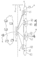
- FIG 2a illustrates a prior art concept of independent Smart Grid network segments 24 managed by a single Smart Grid operator ICT network 25.
- a plurality of gateways 21 communicate with a concentrator 20 of the Smart Grid operator ICT network 25.
- the gateways 21 are connected to a number of home networks 23 with end user equipment 22. Troubleshooting can take place either from inside of the home network 23, see arrow 28, or from outside of the home network 23, see arrow 29.
- the scenario with multiple Smart Grid operators is illustrated in figure 2b .
- an interference problem between Net B and Net C cannot be resolved. This is because both of these concepts are limited by the fact that only information from within each 'physical' network can be obtained and this information is considered independently.
- An object of embodiments of the invention is to provide an over the top dynamic management and coordination mechanism for multiple Smart Grid network segments supported by a number of service/network operators. This will enable a centralized mechanism over different service/network providers for efficient coordination of different information. Such a solution may be particularly valuable for countries where different smart grid parts are not owned by a single company. In particular, exemplary embodiments are valuable for G.hnem network deployments.
- the smart grid network comprises a first smart grid operator network 35 (OP1) having a first plurality of smart grid devices (not shown), and a second smart grid operator network 35 (OP2) having a second plurality of smart grid devices (not shown), and a third smart grid operator network 35 (OP3) having a third plurality of smart grid devices (not shown).
- OP1 comprises a HV grid, a MV grid and a LV grid
- OP2 comprises only a HV grid
- the third smart grid operator network 35 (OP3) comprises only a MV grid.
- other combinations are equally possible.
- the system comprises a first plurality of concentrators 31 associated with said first operator network 35 (OP1), each concentrator thereof being configured for collecting first data from said first plurality of smart grid devices; and for sending said collected data in processed or raw form to a first data coordination centre 30.
- the first data coordination centre comprises a HV, a MV and a LV data coordination centre.
- the system further comprises a second plurality of concentrators (not shown) associated with said second operator network 35 (OP2), each concentrator thereof being configured for collecting second data from the second plurality of smart grid devices; and for sending said collected data in processed or raw form to a second data coordination centre 30.
- the system also comprises a third plurality of concentrators (not shown) associated with the third operator network 35 (OP2), each concentrator thereof being configured for collecting third data from the third plurality of smart grid devices; and for sending said collected data in processed or raw form to a third data coordination centre 30.
- OP2 third operator network 35
- the system comprises a management system 37 configured for receiving said collected first, second and third data in optionally further processed form or in raw form from the first, second, and third data coordination centres 30; and for communicating a troubleshooting strategy to the first and/or second and/or third data coordination centre 30 based on the received first, second and third data, depending on the smart grid devices that are involved in the problem.
- the management system may configured to automatically detect any problems in the smart grid network of any of the operators, or may be operated when a problem is discovered in any of the operator networks OP1, OP2, OP3, upon request of the operator network that is experiencing a problem.
- the first, second and third concentrators 31 may be further configured to receive instructions from the first, second and third data coordination centres 30 based on the communicated trouble shooting strategy, respectively, and to adjust a setting of a smart grid device of said first, second and third plurality of smart grid devices in function of the received instructions, respectively.
- the data collected by the concentrators 31 may comprise values for any one or more of the following parameters of a smart grid device:
- the management system 37 may be configured to compare a physical layer parameter of a first smart grid device of the first operator network 35 (OP1) with the same physical layer parameter of a second smart grid device of the second operator network 35 (OP2), and to communicate a troubleshooting strategy in the form of a reconfiguration of the same or a different physical layer parameter.
- the management system 37 may be configured to compare a network layer parameter of a first smart grid device of the first operator network 35 (OP1) with the same network layer parameter of a second smart grid device of the second operator network 35 (OP2), and to communicate a troubleshooting strategy in the form of a reconfiguration of the same or a different network layer parameter.
- the management system 37 may communicate the strategy to a concentrator 31, e.g. via a specifically adapted API interfaces, and the concentrator may configure the smart grid devices e.g. via further remote management API interfaces or via a standardized protocol such as the TR-069 remote management protocol.
- the management system 27, the data concentration centres 31, the coordinators 30, and the smart grid devices may all be IP devices configured to communicate via the TR-069 protocol to reconfigure a smart grid device in accordance with the determined troubleshooting strategy.
- the management system 37, the data coordination centres 30, and the first and second plurality of concentrators 31 are provided with a remote management application programming interface such that remote calls can be sent via the remote management application programming interfaces from the management system 37 in order to be able to efficiently reconfigure a smart grid device.
- the remote management application programming interface may be configured for sending suitable instructions in order to reconfigure any one or more of the following parameters of a smart grid device: a physical layer parameter such as a used channel, an available channel; a measurable parameter, such as transmit power, channel gain, SNR; a network layer parameter such as a device identification, a MAC address, user identification, IP address, network identification.
- An embodiment of a system of the invention for use in a multiple operator smart grid is given in the following example where the operated channel (henceforth channel) is used as an example physical parameter.
- Other physical or higher layer home network parameters such as power, channel gain, MAC address, user ID, IP address, etc., can also be used.
- access technology There is no constraint on access technology since both wireless and wireline technologies can be used in this example.
- the unique benefit of embodiments of the invention is the fact that dynamic management and coordination of multiple smart grid network segments owned by multiple service operators is possible at single coordinated location.
- the operators will be coordinated and able to react and solve the problems that cause wrong reading, loss of data, etc. This way the intervention by the operator's help desk and technicians at the consumer residence may be avoided.
- Embodiments of the invention may take into consideration information from different service operators and may provide recommendations to solve problems experienced by smart grid network segments/users for each of the operators. This solution may also prevent interventions by an operator technician at the customer premises, does not involve any human intervention, reduces the operator's operational costs, and reduces response time and the number of customer complaints at help desk.
- program storage devices e.g., digital data storage media, which are machine or computer readable and encode machine-executable or computer-executable programs of instructions, wherein said instructions perform some or all of the steps of said above-described methods.
- the program storage devices may be, e.g., digital memories, magnetic storage media such as a magnetic disks and magnetic tapes, hard drives, or optically readable digital data storage media.
- the embodiments are also intended to cover computers programmed to perform said steps of the above-described methods.
- processors may be provided through the use of dedicated hardware as well as hardware capable of executing software in association with appropriate software.
- the functions may be provided by a single dedicated processor, by a single shared processor, or by a plurality of individual processors, some of which may be shared.
- processor or “controller” should not be construed to refer exclusively to hardware capable of executing software, and may implicitly include, without limitation, digital signal processor (DSP) hardware, network processor, application specific integrated circuit (ASIC), field programmable gate array (FPGA), read only memory (ROM) for storing software, random access memory (RAM), and non volatile storage.
- DSP digital signal processor
- ASIC application specific integrated circuit
- FPGA field programmable gate array
- ROM read only memory
- RAM random access memory
- non volatile storage Other hardware, conventional and/or custom, may also be included.
- any switches shown in the FIGS. are conceptual only. Their function may be carried out through the operation of program logic, through dedicated logic, through the interaction of program control and dedicated logic, or even manually, the particular technique being selectable by the implementer as more specifically understood from the context.
- any block diagrams herein represent conceptual views of illustrative circuitry embodying the principles of the invention.
- any flow charts, flow diagrams, state transition diagrams, pseudo code, and the like represent various processes which may be substantially represented in computer readable medium and so executed by a computer or processor, whether or not such computer or processor is explicitly shown.
Abstract
Description
- The field of the invention relates to problem-solving in smart grid networks. Particular embodiments relate to systems, methods and computer program products for performing problem-solving in a smart grid network comprising a first and a second smart grid network owned by a different operator.
- International Telecommunication Union (ITU) G.hnem will enable cost-effective smart grid applications such as distribution automation, advanced metering infrastructure (AMI), demand side management (DSM), grid-to-home communications, home/building energy management, home automation, vehicle-to-grid and vehicle-to-charging station communications.
- In the G.hnem standard different domains are available for the possible communication over different mediums (i.e., wireless, powerline cables, etc.). The available network resources are limited by the network connectivity and a large number of network devices. Home network applications are becoming very popular and they can be provided by more than one network operator. In most developed countries where Smart Grid can be (is) profitable, the grid segments such as generation, transport, distribution and retail are not owned by a single operator due to European Union regulations. These days, it stands to reason that advanced management for home networks will eventually be more demanding. In particular, a remote management mechanism for co-located service operators becomes an important issue.
- Embodiments of the invention aim to provide a system, a method, and a computer program product allowing solving interference problems in a smart grid network comprising a first and a second smart grid network owned by a different operator.
- According to a first aspect of the invention there is provided a system for performing problem solving in a smart grid network, said smart grid network comprising at least a first smart grid operator network having a first plurality of smart grid devices, and a second smart grid operator network having a second plurality of smart grid devices. The system comprises a first plurality of concentrators associated with said first operator network, each concentrator thereof being configured for collecting first data from said first plurality of smart grid devices and for sending said collected data in processed or raw form to a first data coordination centre; a second plurality of concentrators associated with said second operator network, each concentrator thereof being configured for collecting second data from the second plurality of smart grid devices and for sending said collected data in processed or raw form to a second data coordination centre; and a management system. The management system is configured for receiving the collected first and second data in processed form or raw form from the first and second data coordination centres; and for communicating a troubleshooting strategy to the first and/or second data coordination systems based on said received first and second data. The first and second concentrators are further configured to receive instructions from said first and second data coordination centres based on the communicated trouble shooting strategy, respectively, and to adjust a setting of a smart grid device of said first and second plurality of smart grid devices in function of the received instructions, respectively.
- Embodiments are based inter alia on the inventive insight that by providing, on the one hand, concentrators in each smart grid operator network which communicate with a data coordination centre of their grid operator network, and, on the other hand, an "over-the-top" management system, interference problems may be solved more easily, compared to mechanisms that are performed within a single operator network.
- In a preferred embodiment the collected data comprises values for any one or more of the following parameters of a smart grid device: a physical layer parameter such as a used channel, an available channel; a measurable parameter, such as transmit power, channel gain, SNR; a network layer parameter such as a device identification, a MAC address, user identification, IP address, network identification.
- In a preferred embodiment the management system is configured to compare a value for a parameter of a first smart grid device of said first plurality of smart grid devices with a value for the same parameter of a second smart grid device of said second plurality of smart grid devices, and to communicate a troubleshooting strategy in the form of a reconfiguration of the same or a different parameter. In an exemplary embodiment thereof the management system is configured to compare a value for a physical layer parameter of a first smart grid device of said first plurality of smart grid devices with a value for the same physical layer parameter of a second smart grid device of said second plurality of smart grid devices, and to communicate a troubleshooting strategy in the form of a reconfiguration of the same or a different physical layer parameter. In another exemplary embodiment thereof the management system is configured to compare a value for a network layer parameter of a first smart grid device of said first plurality of smart grid devices with a value for the same network layer parameter of a second smart grid device of said second plurality of smart grid devices, and to communicate a troubleshooting strategy in the form of a reconfiguration of the same or a different network layer parameter.
- In a preferred embodiment the management system, the management system, the first and/or second data coordination centre, and the first and second plurality of concentrators are provided with a remote management interface such that a setting of a smart grid device of the first and second plurality of smart grid devices can be adjusted remotely. This may be a custom made remote management application programming interface or a standardized remote management interface using e.g. TR-069 (Technical Report 069, a Broadband Forum technical specification entitled CPE WAN Management Protocol (CWMP)) or the Open Mobile Alliance (OMA) Device Management (DM) (OMA-DM) protocol. Note that it is possible to use a combination of custom made and standardized interfaces. More in particular the remote management application programming interface may be configured for sending remote calls in order to reconfigure any one or more of the following parameters of a smart grid device: a physical layer parameter such as a used channel, an available channel; a measurable parameter, such as transmit power, channel gain, SNR; a network layer parameter such as a device identification, a MAC address, user identification, IP address, network identification.
- In an exemplary embodiment the first and/or second operator network comprises any one or more of the following domain: a high voltage (HV) smart grid segment, a medium voltage (MV) smart grid segment, a low voltage (LV) smart grid segment; and wherein the said first and second plurality of concentrators comprises at least one concentrator for each segment, respectively.
- According to a second aspect of the invention there is provided a method for performing problem solving in a smart grid network, said smart grid network comprising at least a first smart grid operator network having a first plurality of smart grid devices, and a second smart grid operator network having a second plurality of smart grid devices. The method comprises: in said first smart grid operator network, collecting first data from the first plurality of smart grid devices; and sending the collected data in processed or raw form to a first data coordination centre; in said second smart grid operator network, collecting second data from the second plurality of smart grid devices; and sending the collected data in processed or raw form to a second data coordination centre; processing the collected first and second data and communicating a troubleshooting strategy to the first and/or second data coordination systems based on the processed first and second data; and adjusting a setting of a smart grid device of said first and second plurality of smart grid devices in function of the communicated trouble shooting strategy.
- According to a preferred embodiment the collected data comprises values for any one or more of the following parameters of a smart grid device: a physical layer parameter such as a used channel, an available channel; a measurable parameter, such as transmit power, channel gain, SNR; a network layer parameter such as a device identification, a MAC address, user identification, IP address, network identification.
- According to a preferred embodiment the processing comprises comparing a value for a parameter of a first smart grid device of said first plurality of smart grid devices with a value for the same parameter of a second smart grid device of said second plurality of smart grid devices, and communicating a troubleshooting strategy in the form of a reconfiguration of the same or a different parameter. According to an exemplary embodiment thereof the processing comprises comparing a value for a physical layer parameter of a first smart grid device of said first plurality of smart grid devices with a value for the same physical layer parameter of a second smart grid device of said second plurality of smart grid devices, and communicating a troubleshooting strategy in the form of a reconfiguration of the same or a different physical layer parameter. According to another exemplary embodiment thereof the processing comprises comparing a value for a network layer parameter of a first smart grid device of said first plurality of smart grid devices with a value for the same network layer parameter of a second smart grid device of said second plurality of smart grid devices, and to communicate a troubleshooting strategy in the form of a reconfiguration of the same or a different network layer parameter.
- In the context of the present invention the smart grid device may be e.g. a sensor or a communication modem. The term sensor component may refer to any sensor, any metering device, or any other device capable of performing measurements, and the sensor component is further configured for sending data messages to at least one concentrator, optionally via one or more substation components. The term substation component refers to a communication device used for performing an assist communication function, also called a relay function between the sensor components and the concentrators.
- In the context of the present invention the term concentrator refers to a control entity communicating with a plurality of smart grid devices and configured for performing control tasks and for sending control messages to the smart grid devices, optionally via one or more substation components. More in particular a concentrator os configured for obtaining parameter data from the surrounding smart grid devices. One concentrator may manage e.g. between 1000 and 500.000 smart grid devices. In a smart grid operator network typically more than 10, and e.g. between 50 and 200 concentrators may be provided, depending on the size of the network. A control component has functionalities to allocate and coordinate network devices and resources of the smart grid network, and may be further configured to analyze the data messages received from the sensor components. The concentrators, any substations and the smart grid devices are IP enabled devices, and the exchanged packets contained in the message signals are sent via an IP protocol.
- According to a further aspect of the invention, there is provided a computer program comprising computer-executable instructions to perform the method, when the program is run on a computer, according to any one of the steps of any one of the embodiments disclosed above.
- According to a further aspect of the invention, there is provided a computer device or other hardware device programmed to perform one or more steps of any one of the embodiments of the method disclosed above. According to another aspect there is provided a data storage device encoding a program in machine-readable and machine-executable form to perform one or more steps of any one of the embodiments of the method disclosed above.
- The accompanying drawings are used to illustrate presently preferred non-limiting exemplary embodiments of devices of the present invention. The above and other advantages of the features and objects of the invention will become more apparent and the invention will be better understood from the following detailed description when read in conjunction with the accompanying drawings, in which:
-
Figure 1 illustrates schematically a smart grid architecture; -
Figures 2A and2B illustrate respectively the diagnostics and trouble-shooting concept and problems that may occur when performing trouble-shooting within an operator network in the case a multi-operator smart grid network; -
Figure 3 illustrates an exemplary embodiment of a system of the invention; and -
Figures 4A-4D illustrate an exemplary embodiment of a method of the invention. -
Figure 1 illustrates the schematic of an operations support systems (OSS) solution for a single Smart Grid operator. Currently, only solutions designed for a single operator who is the network owner are available. However, in most developed countries where Smart Grid can be (is) profitable the grid segments such as generation, transport, distribution and retail are not owned by a single operator due to European Union regulations. - To support the exchanges of smart grid's sensor information and control messages an ICT communication network is required.
Figure 1 illustrates schematically a smart grid ICT network with a single smart grid operator. For a smart grid ICT network several communication technologies are available: power line communication (PLC), copper or optical fiber, and wireless communication (ad-hoc, mesh and cellular architectures). The core HV network is established by optical communications, while MV and LV networks may use various technologies such as wireless (LTE, GSM, Wimax), power line communication (PLC) and fiber-to-the-home (FTTH). The most common solution is PLC since it is easy to exploit the existing wired infrastructure and the deployment cost is greatly reduced. In addition, protocols like Ethernet, IPv4 and IPv6, are supported in smart grid networks and enable an easy integration with other IP-based networks via multi-protocol label switching (MPLS). The G.hnem standard developed by ITU-T supports power lines as a physical layer for controlling power utilities. G.hnem also supports the higher layer applications protocols like Ethernet, IPv4 and IPv6, as a result of which G.hnem compliant power grid communication networks can be easily integrated with IP-based networks. In that way there is provided a link between electricity networks and communications networks, enabling utilities to exercise a higher level of monitoring and control of the power grid. -
Figure 2a illustrates a prior art concept of independent SmartGrid network segments 24 managed by a single Smart Gridoperator ICT network 25. A plurality ofgateways 21 communicate with aconcentrator 20 of the Smart Gridoperator ICT network 25. Thegateways 21 are connected to a number ofhome networks 23 withend user equipment 22. Troubleshooting can take place either from inside of thehome network 23, seearrow 28, or from outside of thehome network 23, seearrow 29. The scenario with multiple Smart Grid operators is illustrated infigure 2b . In both examples offigure 2a and2b an interference problem between Net B and Net C cannot be resolved. This is because both of these concepts are limited by the fact that only information from within each 'physical' network can be obtained and this information is considered independently. This kind of diagnosis will provide a sub-optimal management since disruptive effects between different home networks from single or multiple service operators is not taken into consideration. Consequently, manual network solutions by operator's technicians or the customer himself is highly likely, and a user complaint will typically trigger the dispatch of technicians to investigate the problem. This procedure is very time consuming and highly costly. Thus, a more proactive dynamic management and coordination of different home networks is an object of embodiments of the invention. - Some monitoring features for single Smart Grid operator solutions are available in the market, see for example the solutions of by the company Power Plus Communications (PPC). Motive's M2M Communication Control (CC) and M2M Service Management (SM) R2.0 single operator solution also support monitoring functions.
- An object of embodiments of the invention is to provide an over the top dynamic management and coordination mechanism for multiple Smart Grid network segments supported by a number of service/network operators. This will enable a centralized mechanism over different service/network providers for efficient coordination of different information. Such a solution may be particularly valuable for countries where different smart grid parts are not owned by a single company. In particular, exemplary embodiments are valuable for G.hnem network deployments.
- A system for performing problem solving in a smart grid network by using a dynamic management and coordination mechanism is illustrated in
figure 3 . The smart grid network comprises a first smart grid operator network 35 (OP1) having a first plurality of smart grid devices (not shown), and a second smart grid operator network 35 (OP2) having a second plurality of smart grid devices (not shown), and a third smart grid operator network 35 (OP3) having a third plurality of smart grid devices (not shown). It is assumed that the first smart grid operator network 35 (OP1) comprises a HV grid, a MV grid and a LV grid, while the second smart grid operator network 35 (OP2) comprises only a HV grid, and the third smart grid operator network 35 (OP3) comprises only a MV grid. Of course, other combinations are equally possible. The system comprises a first plurality ofconcentrators 31 associated with said first operator network 35 (OP1), each concentrator thereof being configured for collecting first data from said first plurality of smart grid devices; and for sending said collected data in processed or raw form to a firstdata coordination centre 30. In the illustrated example the first data coordination centre comprises a HV, a MV and a LV data coordination centre. The system further comprises a second plurality of concentrators (not shown) associated with said second operator network 35 (OP2), each concentrator thereof being configured for collecting second data from the second plurality of smart grid devices; and for sending said collected data in processed or raw form to a seconddata coordination centre 30. The system also comprises a third plurality of concentrators (not shown) associated with the third operator network 35 (OP2), each concentrator thereof being configured for collecting third data from the third plurality of smart grid devices; and for sending said collected data in processed or raw form to a thirddata coordination centre 30. - The system comprises a
management system 37 configured for receiving said collected first, second and third data in optionally further processed form or in raw form from the first, second, and third data coordination centres 30; and for communicating a troubleshooting strategy to the first and/or second and/or thirddata coordination centre 30 based on the received first, second and third data, depending on the smart grid devices that are involved in the problem. The management system may configured to automatically detect any problems in the smart grid network of any of the operators, or may be operated when a problem is discovered in any of the operator networks OP1, OP2, OP3, upon request of the operator network that is experiencing a problem. - The first, second and
third concentrators 31 may be further configured to receive instructions from the first, second and third data coordination centres 30 based on the communicated trouble shooting strategy, respectively, and to adjust a setting of a smart grid device of said first, second and third plurality of smart grid devices in function of the received instructions, respectively. - The data collected by the
concentrators 31 may comprise values for any one or more of the following parameters of a smart grid device: - a physical layer parameter such as a used channel, an available channel;
- a measurable parameter, such as transmit power, channel gain, SNR;
- a network layer parameter such as a device identification, a MAC address, user identification, IP address, network identification.
- The
management system 37 may be configured to compare a physical layer parameter of a first smart grid device of the first operator network 35 (OP1) with the same physical layer parameter of a second smart grid device of the second operator network 35 (OP2), and to communicate a troubleshooting strategy in the form of a reconfiguration of the same or a different physical layer parameter. - Alternatively or in addition the
management system 37 may be configured to compare a network layer parameter of a first smart grid device of the first operator network 35 (OP1) with the same network layer parameter of a second smart grid device of the second operator network 35 (OP2), and to communicate a troubleshooting strategy in the form of a reconfiguration of the same or a different network layer parameter. - More in particular, the
management system 37 may communicate the strategy to aconcentrator 31, e.g. via a specifically adapted API interfaces, and the concentrator may configure the smart grid devices e.g. via further remote management API interfaces or via a standardized protocol such as the TR-069 remote management protocol. Alternatively, the management system 27, the data concentration centres 31, thecoordinators 30, and the smart grid devices may all be IP devices configured to communicate via the TR-069 protocol to reconfigure a smart grid device in accordance with the determined troubleshooting strategy. - In a preferred embodiment the
management system 37, the data coordination centres 30, and the first and second plurality ofconcentrators 31 are provided with a remote management application programming interface such that remote calls can be sent via the remote management application programming interfaces from themanagement system 37 in order to be able to efficiently reconfigure a smart grid device. More in particular the remote management application programming interface may be configured for sending suitable instructions in order to reconfigure any one or more of the following parameters of a smart grid device: a physical layer parameter such as a used channel, an available channel; a measurable parameter, such as transmit power, channel gain, SNR; a network layer parameter such as a device identification, a MAC address, user identification, IP address, network identification. - An embodiment of a system of the invention for use in a multiple operator smart grid is given in the following example where the operated channel (henceforth channel) is used as an example physical parameter. Other physical or higher layer home network parameters such as power, channel gain, MAC address, user ID, IP address, etc., can also be used. There is no constraint on access technology since both wireless and wireline technologies can be used in this example.
- Let us assume a scenario with several Smart Grid access networks (Nets A, B, C and D) within the same residential dwellings as shown in
figure 4A . In this scenario the focus is put on an exemplary case where Smart Grid is extended over apartment buildings where several different operators may offer their services. Thus, infigure 4A , only a low voltage (LV) (supply) Smart Grid segment is considered. Of course an implementation of this solution may take into consideration different grid segments as well. In this case the problems are more likely to happen if there is no additional solution to manage the Smart Grid application providers. - It is assumed that for example networks B and C are experiencing problems since the same channel 11 (Ch 11) is used across both home networks from different Smart Grid operators. Consequently, the customer information may not be reliable and its service may be degraded. According to an exemplary embodiment of the method, over the top management and coordination is foreseen in the following steps:
- [Step 1], see
figure 4A : a first data coordination centre indicated asremote server 1 ofoperator network 1 is able to access the available network parameters (such as signal power, used and available channels, network SID, device ID, etc.) or to order the parameter collection through a concentrator ofoperator network 1. The concentrator ofoperator network 1 is able to collect amongst others the parameters Ch2 and Ch11 of a smart grid device of Net C. In a similar way a second data coordination centre indicated asremote server 2 ofoperator network 2 is able to access the available network parameters or to order the parameter collection through a concentrator ofoperator network 2. The concentrator ofoperator network 2 is able to collect amongst others the parameters Ch7 and Ch11 of a smart grid device of Net B. The parameters may be collected using e.g. SNMP or TR-069 protocols. The parameters collected byremote server respective servers operator network - [Step 2], see
figure 4B : the collected parameters are processed at the operator level byremote servers remote server 1 and/or 2 to the "over-the-top" management system, e.g. in the form of a remote server configured with a remote management application programming interface (OSS API), see alsofigure 4C . Note that it is also possible to always send collected raw or pre-processed parameters to the "over-the-top" management system, and to make the trouble shooting of problems with the same operating network also the task of the "over-the-top" management system. - [Step 3], see
figure 4C : based on input parameters and specified user and operator requirements (e.g., problem assessment/level, decision policy, priority lists, etc.) the proposed method recommends a coordination strategy to theremote servers figure 4C . These API interfaces should then be integrated in the smart grid devices, the gateways and the concentrators to enable efficient data delivery. Alternatively the management system, the smart grid devices, the gateways and the concentrators may be configured to communicate via a standardized remote management interface such as TR-069 or the Open Mobile Alliance (OMA) Device Management (DM) (OMA-DM) protocol. Also, a combination of custom made (e.g. specific for a particular smart grid device) and standardized interfaces may be used. - [Step 4], see
figure 4D : the reconfiguration is initiated to optimize the network usage for both operator networks as shown infigure 4D . - The unique benefit of embodiments of the invention is the fact that dynamic management and coordination of multiple smart grid network segments owned by multiple service operators is possible at single coordinated location. The operators will be coordinated and able to react and solve the problems that cause wrong reading, loss of data, etc. This way the intervention by the operator's help desk and technicians at the consumer residence may be avoided.
- Embodiments of the invention may take into consideration information from different service operators and may provide recommendations to solve problems experienced by smart grid network segments/users for each of the operators. This solution may also prevent interventions by an operator technician at the customer premises, does not involve any human intervention, reduces the operator's operational costs, and reduces response time and the number of customer complaints at help desk.
- A person of skill in the art would readily recognize that steps of various above-described methods can be performed by programmed computers. Herein, some embodiments are also intended to cover program storage devices, e.g., digital data storage media, which are machine or computer readable and encode machine-executable or computer-executable programs of instructions, wherein said instructions perform some or all of the steps of said above-described methods. The program storage devices may be, e.g., digital memories, magnetic storage media such as a magnetic disks and magnetic tapes, hard drives, or optically readable digital data storage media. The embodiments are also intended to cover computers programmed to perform said steps of the above-described methods.
- The functions of the various elements shown in the figures, including any functional blocks labelled as "processors" or "modules", may be provided through the use of dedicated hardware as well as hardware capable of executing software in association with appropriate software. When provided by a processor, the functions may be provided by a single dedicated processor, by a single shared processor, or by a plurality of individual processors, some of which may be shared. Moreover, explicit use of the term "processor" or "controller" should not be construed to refer exclusively to hardware capable of executing software, and may implicitly include, without limitation, digital signal processor (DSP) hardware, network processor, application specific integrated circuit (ASIC), field programmable gate array (FPGA), read only memory (ROM) for storing software, random access memory (RAM), and non volatile storage. Other hardware, conventional and/or custom, may also be included. Similarly, any switches shown in the FIGS. are conceptual only. Their function may be carried out through the operation of program logic, through dedicated logic, through the interaction of program control and dedicated logic, or even manually, the particular technique being selectable by the implementer as more specifically understood from the context.
- It should be appreciated by those skilled in the art that any block diagrams herein represent conceptual views of illustrative circuitry embodying the principles of the invention. Similarly, it will be appreciated that any flow charts, flow diagrams, state transition diagrams, pseudo code, and the like represent various processes which may be substantially represented in computer readable medium and so executed by a computer or processor, whether or not such computer or processor is explicitly shown.
- Whilst the principles of the invention have been set out above in connection with specific embodiments, it is to be understood that this description is merely made by way of example and not as a limitation of the scope of protection which is determined by the appended claims.
Claims (14)
- A system for performing problem solving in a smart grid network, said smart grid network comprising at least a first smart grid operator network having a first plurality of smart grid devices, and a second smart grid operator network having a second plurality of smart grid devices;
said system comprising:a first plurality of concentrators associated with said first operator network, each concentrator thereof being configured for collecting first data from said first plurality of smart grid devices; and for sending said collected data in processed or raw form to a first data coordination centre;a second plurality of concentrators associated with said second operator network, each concentrator thereof being configured for collecting second data from the second plurality of smart grid devices; and for sending said collected data in processed or raw form to a second data coordination centre;a management system configured for receiving said collected first and second data in processed or raw form from said first and second data coordination centres; and for communicating a troubleshooting strategy to said first and/or second data coordination systems based on said received first and second data;wherein each first and second concentrator is further configured to receive instructions from said first and second data coordination centres based on the communicated trouble shooting strategy, respectively, and to adjust a setting of a smart grid device of said first and second plurality of smart grid devices in function of the received instructions, respectively. - The system of claim 1, wherein the collected data comprises values for any one or more of the following parameters of a smart grid device:a physical layer parameter such as a used channel, an available channel;a measurable parameter, such as transmit power, channel gain, SNR;a network layer parameter such as a device identification, a MAC address, user identification, IP address, network identification.
- The system of claim 2, wherein the management system is configured to compare a value for a physical layer parameter of a first smart grid device of said first plurality of smart grid devices with a value for the same physical layer parameter of a second smart grid device of said second plurality of smart grid devices, and to communicate a troubleshooting strategy in the form of a reconfiguration of the same or a different physical layer parameter.
- The system of claim 2 or 3, wherein the management system is configured to compare a value for a network layer parameter of a first smart grid device of said first plurality of smart grid devices with a value for the same network layer parameter of a second smart grid device of said second plurality of smart grid devices, and to communicate a troubleshooting strategy in the form of a reconfiguration of the same or a different network layer parameter.
- The system of any one of the previous claims, wherein the management system, the first and/or second data coordination centre, and the first and second plurality of concentrators are provided with a remote management interface such that a setting of a smart grid device of the first and second plurality of smart grid devices can be adjusted remotely.
- The system of claim 5, wherein the remote management interface is configured for adjusting any one or more of the following parameters of a smart grid device:a physical layer parameter such as a used channel, an available channel;a measurable parameter, such as transmit power, channel gain, SNR;a network layer parameter such as a device identification, a MAC address, user identification, IP address, network identification.
- The system of any one of the previous claims, wherein said first and/or said second operator network comprises any one or more of the following domain: a high voltage (HV) smart grid segment, a medium voltage (MV) smart grid segment, a low voltage (LV) smart grid segment; and wherein the said first and second plurality of concentrators comprises at least one concentrator for each segment, respectively.
- A method for performing problem solving in a smart grid network, said smart grid network comprising at least a first smart grid operator network having a first plurality of smart grid devices, and a second smart grid operator network having a second plurality of smart grid devices;
said method comprising:in said first smart grid operator network, collecting first data from said first plurality of smart grid devices; and sending said collected data in processed or raw form to a first data coordination centre;in said second smart grid operator network, collecting second data from the second plurality of smart grid devices; and sending said collected data in processed or raw form to a second data coordination centre;processing said collected first and second data and communicating a troubleshooting strategy to said first and/or second data coordination systems based on said processed first and second data;adjusting a setting of a smart grid device of said first and second plurality of smart grid devices in function of the communicated trouble shooting strategy. - The method of claim 8, wherein the collected data comprises values for any one or more of the following parameters of a smart grid device:a physical layer parameter such as a used channel, an available channel;a measurable parameter, such as transmit power, channel gain, SNR;a network layer parameter such as a device identification, a MAC address, user identification, IP address, network identification.
- The method of claim 9, wherein the processing comprises comparing a value for a physical layer parameter of a first smart grid device of said first plurality of smart grid devices with a value for the same physical layer parameter of a second smart grid device of said second plurality of smart grid devices, and communicating a troubleshooting strategy in the form of a reconfiguration of the same or a different physical layer parameter.
- The method of claim 9 or 10, wherein the processing comprises comparing a value for a network layer parameter of a first smart grid device of said first plurality of smart grid devices with a value for the same network layer parameter of a second smart grid device of said second plurality of smart grid devices, and to communicate a troubleshooting strategy in the form of a reconfiguration of the same or a different network layer parameter.
- The method of any one of the claims 8-11, wherein the processing comprises comparing a value for a parameter of a first smart grid device of said first plurality of smart grid devices with a value for the same parameter of a second smart grid device of said second plurality of smart grid devices, and communicating a troubleshooting strategy in the form of a reconfiguration of the same or a different parameter.
- A computer program comprising computer-executable instructions to perform one or more steps of the method of any one of the claims 8-12, when the program is run on a computer.
- A computer program product comprising computer-executable instructions for performing one or more steps of the method of any one of the claims 8-12, when the program is run on a computer.
Priority Applications (1)
| Application Number | Priority Date | Filing Date | Title |
|---|---|---|---|
| EP14305466.6A EP2927644B1 (en) | 2014-03-31 | 2014-03-31 | System and method for performing problem-solving in smart grid networks |
Applications Claiming Priority (1)
| Application Number | Priority Date | Filing Date | Title |
|---|---|---|---|
| EP14305466.6A EP2927644B1 (en) | 2014-03-31 | 2014-03-31 | System and method for performing problem-solving in smart grid networks |
Publications (2)
| Publication Number | Publication Date |
|---|---|
| EP2927644A1 true EP2927644A1 (en) | 2015-10-07 |
| EP2927644B1 EP2927644B1 (en) | 2018-08-15 |
Family
ID=50639399
Family Applications (1)
| Application Number | Title | Priority Date | Filing Date |
|---|---|---|---|
| EP14305466.6A Not-in-force EP2927644B1 (en) | 2014-03-31 | 2014-03-31 | System and method for performing problem-solving in smart grid networks |
Country Status (1)
| Country | Link |
|---|---|
| EP (1) | EP2927644B1 (en) |
Cited By (9)
| Publication number | Priority date | Publication date | Assignee | Title |
|---|---|---|---|---|
| CN105226652A (en) * | 2015-10-30 | 2016-01-06 | 许继集团有限公司 | A kind of smart power grid user side energy-saving control method |
| CN107423912A (en) * | 2017-08-02 | 2017-12-01 | 长威信息科技发展股份有限公司 | A kind of method and system for becoming dynamic mesh dynamic division based on personnel |
| CN107451740A (en) * | 2017-08-02 | 2017-12-08 | 长威信息科技发展股份有限公司 | A kind of method and system of the scheduling of resource changed based on grid cell |
| CN107733987A (en) * | 2017-09-08 | 2018-02-23 | 河北建设集团股份有限公司 | A kind of job site water power control system and its control method |
| CN108583343A (en) * | 2018-05-24 | 2018-09-28 | 北京科佳同创新能源科技有限公司 | A kind of charging station energy scheduling system and method |
| CN109302303A (en) * | 2018-07-11 | 2019-02-01 | 上海电力学院 | One kind is provided multiple forms of energy to complement each other energy internal layer control system |
| CN111339090A (en) * | 2020-02-22 | 2020-06-26 | 国网山东省电力公司宁阳县供电公司 | Power grid distribution network data processing system and method |
| CN112398124A (en) * | 2020-11-10 | 2021-02-23 | 杭州市电力设计院有限公司余杭分公司 | Optimization control method, device and equipment for regional micro-grid and readable storage medium |
| CN113221302A (en) * | 2021-05-26 | 2021-08-06 | 上海天麦能源科技有限公司 | Smart city detection data dynamic gridding processing method and system |
Citations (5)
| Publication number | Priority date | Publication date | Assignee | Title |
|---|---|---|---|---|
| DE4321458A1 (en) * | 1993-06-29 | 1995-01-12 | Alcatel Network Services | Network management support method and network management facility therefor |
| EP0942573A2 (en) * | 1998-03-12 | 1999-09-15 | Alcatel | Intelligent network service for centralized allocation to network operators of failure signals in a multi-operator environment |
| US20070124026A1 (en) * | 2005-11-30 | 2007-05-31 | Alternative Energy Systems Consulting, Inc. | Agent Based Auction System and Method for Allocating Distributed Energy Resources |
| US20110137876A1 (en) * | 2009-12-07 | 2011-06-09 | Yeh Peter Zei-Chan | Data quality enhancement for smart grid applications |
| US20130106617A1 (en) * | 2011-11-01 | 2013-05-02 | Kt Corporation | Smart metering system using white space band and smart metering method using the same |
Family Cites Families (1)
| Publication number | Priority date | Publication date | Assignee | Title |
|---|---|---|---|---|
| EP2584735B1 (en) * | 2011-08-30 | 2016-07-06 | Alcatel Lucent | Method and system for troubleshooting in in-house networks |
-
2014
- 2014-03-31 EP EP14305466.6A patent/EP2927644B1/en not_active Not-in-force
Patent Citations (5)
| Publication number | Priority date | Publication date | Assignee | Title |
|---|---|---|---|---|
| DE4321458A1 (en) * | 1993-06-29 | 1995-01-12 | Alcatel Network Services | Network management support method and network management facility therefor |
| EP0942573A2 (en) * | 1998-03-12 | 1999-09-15 | Alcatel | Intelligent network service for centralized allocation to network operators of failure signals in a multi-operator environment |
| US20070124026A1 (en) * | 2005-11-30 | 2007-05-31 | Alternative Energy Systems Consulting, Inc. | Agent Based Auction System and Method for Allocating Distributed Energy Resources |
| US20110137876A1 (en) * | 2009-12-07 | 2011-06-09 | Yeh Peter Zei-Chan | Data quality enhancement for smart grid applications |
| US20130106617A1 (en) * | 2011-11-01 | 2013-05-02 | Kt Corporation | Smart metering system using white space band and smart metering method using the same |
Cited By (12)
| Publication number | Priority date | Publication date | Assignee | Title |
|---|---|---|---|---|
| CN105226652A (en) * | 2015-10-30 | 2016-01-06 | 许继集团有限公司 | A kind of smart power grid user side energy-saving control method |
| CN105226652B (en) * | 2015-10-30 | 2017-11-03 | 许继集团有限公司 | A kind of smart power grid user side energy-saving control method |
| CN107423912A (en) * | 2017-08-02 | 2017-12-01 | 长威信息科技发展股份有限公司 | A kind of method and system for becoming dynamic mesh dynamic division based on personnel |
| CN107451740A (en) * | 2017-08-02 | 2017-12-08 | 长威信息科技发展股份有限公司 | A kind of method and system of the scheduling of resource changed based on grid cell |
| CN107733987A (en) * | 2017-09-08 | 2018-02-23 | 河北建设集团股份有限公司 | A kind of job site water power control system and its control method |
| CN108583343A (en) * | 2018-05-24 | 2018-09-28 | 北京科佳同创新能源科技有限公司 | A kind of charging station energy scheduling system and method |
| CN109302303A (en) * | 2018-07-11 | 2019-02-01 | 上海电力学院 | One kind is provided multiple forms of energy to complement each other energy internal layer control system |
| CN111339090A (en) * | 2020-02-22 | 2020-06-26 | 国网山东省电力公司宁阳县供电公司 | Power grid distribution network data processing system and method |
| CN112398124A (en) * | 2020-11-10 | 2021-02-23 | 杭州市电力设计院有限公司余杭分公司 | Optimization control method, device and equipment for regional micro-grid and readable storage medium |
| CN112398124B (en) * | 2020-11-10 | 2022-06-14 | 杭州市电力设计院有限公司余杭分公司 | Optimization control method, device and equipment for regional micro-grid and readable storage medium |
| CN113221302A (en) * | 2021-05-26 | 2021-08-06 | 上海天麦能源科技有限公司 | Smart city detection data dynamic gridding processing method and system |
| CN113221302B (en) * | 2021-05-26 | 2023-07-28 | 上海天麦能源科技有限公司 | Dynamic gridding processing method and system for smart city detection data |
Also Published As
| Publication number | Publication date |
|---|---|
| EP2927644B1 (en) | 2018-08-15 |
Similar Documents
| Publication | Publication Date | Title |
|---|---|---|
| EP2927644B1 (en) | System and method for performing problem-solving in smart grid networks | |
| US11477108B2 (en) | Systems and methods for jointly optimizing WAN and LAN network communications | |
| Rehmani et al. | Software defined networks-based smart grid communication: A comprehensive survey | |
| US9860111B2 (en) | Method and apparatus for diagnosing and configuring a broadband connection via an alternate communication path | |
| CN104243595B (en) | A kind of power information acquisition system and its method based on IPv6 | |
| Jeon | QoS requirements for the smart grid communications system | |
| US20090322556A1 (en) | Transmission of utility data | |
| CN103974307A (en) | Method for managing ZigBee network in internet of things | |
| CN102594633A (en) | Generating a network map | |
| EP2680494A1 (en) | Home network trouble shooting | |
| CN103765818B (en) | Method and system for the failture evacuation in internal network | |
| JP5618363B2 (en) | Mobile communication system management system, method and apparatus | |
| US11402417B2 (en) | Detection of energy-consumption fraud in an electrical distribution service | |
| EP2854336A1 (en) | Management method for use by a management system | |
| Cackovic et al. | Management in M2M networks | |
| US20230275662A1 (en) | Broadband network slicing selection and control | |
| CN100596142C (en) | A system and method to manage file transmission based on simple network management protocol | |
| Agrawal et al. | Combating distance limitation for communications within Multiple Micro-Grids by Virtual routers | |
| CN104753689B (en) | A kind of user management method of broadband cluster communication system | |
| Rocha | Alternative Solutions for Substation Telecontrol |
Legal Events
| Date | Code | Title | Description |
|---|---|---|---|
| PUAI | Public reference made under article 153(3) epc to a published international application that has entered the european phase |
Free format text: ORIGINAL CODE: 0009012 |
|
| AK | Designated contracting states |
Kind code of ref document: A1 Designated state(s): AL AT BE BG CH CY CZ DE DK EE ES FI FR GB GR HR HU IE IS IT LI LT LU LV MC MK MT NL NO PL PT RO RS SE SI SK SM TR |
|
| AX | Request for extension of the european patent |
Extension state: BA ME |
|
| 17P | Request for examination filed |
Effective date: 20160407 |
|
| RBV | Designated contracting states (corrected) |
Designated state(s): AL AT BE BG CH CY CZ DE DK EE ES FI FR GB GR HR HU IE IS IT LI LT LU LV MC MK MT NL NO PL PT RO RS SE SI SK SM TR |
|
| STAA | Information on the status of an ep patent application or granted ep patent |
Free format text: STATUS: EXAMINATION IS IN PROGRESS |
|
| 17Q | First examination report despatched |
Effective date: 20170322 |
|
| RAP1 | Party data changed (applicant data changed or rights of an application transferred) |
Owner name: ALCATEL LUCENT |
|
| REG | Reference to a national code |
Ref country code: DE Ref legal event code: R079 Ref document number: 602014030364 Country of ref document: DE Free format text: PREVIOUS MAIN CLASS: G01D0004000000 Ipc: H02J0003140000 |
|
| GRAP | Despatch of communication of intention to grant a patent |
Free format text: ORIGINAL CODE: EPIDOSNIGR1 |
|
| STAA | Information on the status of an ep patent application or granted ep patent |
Free format text: STATUS: GRANT OF PATENT IS INTENDED |
|
| RIC1 | Information provided on ipc code assigned before grant |
Ipc: G06Q 10/06 20120101ALI20180426BHEP Ipc: G06Q 50/06 20120101ALI20180426BHEP Ipc: G01D 4/00 20060101ALI20180426BHEP Ipc: H02J 3/14 20060101AFI20180426BHEP |
|
| INTG | Intention to grant announced |
Effective date: 20180518 |
|
| GRAS | Grant fee paid |
Free format text: ORIGINAL CODE: EPIDOSNIGR3 |
|
| GRAA | (expected) grant |
Free format text: ORIGINAL CODE: 0009210 |
|
| STAA | Information on the status of an ep patent application or granted ep patent |
Free format text: STATUS: THE PATENT HAS BEEN GRANTED |
|
| AK | Designated contracting states |
Kind code of ref document: B1 Designated state(s): AL AT BE BG CH CY CZ DE DK EE ES FI FR GB GR HR HU IE IS IT LI LT LU LV MC MK MT NL NO PL PT RO RS SE SI SK SM TR |
|
| REG | Reference to a national code |
Ref country code: CH Ref legal event code: EP Ref country code: GB Ref legal event code: FG4D Ref country code: AT Ref legal event code: REF Ref document number: 1030882 Country of ref document: AT Kind code of ref document: T Effective date: 20180815 |
|
| REG | Reference to a national code |
Ref country code: IE Ref legal event code: FG4D |
|
| REG | Reference to a national code |
Ref country code: DE Ref legal event code: R096 Ref document number: 602014030364 Country of ref document: DE |
|
| REG | Reference to a national code |
Ref country code: NL Ref legal event code: MP Effective date: 20180815 |
|
| REG | Reference to a national code |
Ref country code: LT Ref legal event code: MG4D |
|
| REG | Reference to a national code |
Ref country code: AT Ref legal event code: MK05 Ref document number: 1030882 Country of ref document: AT Kind code of ref document: T Effective date: 20180815 |
|
| PG25 | Lapsed in a contracting state [announced via postgrant information from national office to epo] |
Ref country code: RS Free format text: LAPSE BECAUSE OF FAILURE TO SUBMIT A TRANSLATION OF THE DESCRIPTION OR TO PAY THE FEE WITHIN THE PRESCRIBED TIME-LIMIT Effective date: 20180815 Ref country code: FI Free format text: LAPSE BECAUSE OF FAILURE TO SUBMIT A TRANSLATION OF THE DESCRIPTION OR TO PAY THE FEE WITHIN THE PRESCRIBED TIME-LIMIT Effective date: 20180815 Ref country code: BG Free format text: LAPSE BECAUSE OF FAILURE TO SUBMIT A TRANSLATION OF THE DESCRIPTION OR TO PAY THE FEE WITHIN THE PRESCRIBED TIME-LIMIT Effective date: 20181115 Ref country code: NO Free format text: LAPSE BECAUSE OF FAILURE TO SUBMIT A TRANSLATION OF THE DESCRIPTION OR TO PAY THE FEE WITHIN THE PRESCRIBED TIME-LIMIT Effective date: 20181115 Ref country code: GR Free format text: LAPSE BECAUSE OF FAILURE TO SUBMIT A TRANSLATION OF THE DESCRIPTION OR TO PAY THE FEE WITHIN THE PRESCRIBED TIME-LIMIT Effective date: 20181116 Ref country code: SE Free format text: LAPSE BECAUSE OF FAILURE TO SUBMIT A TRANSLATION OF THE DESCRIPTION OR TO PAY THE FEE WITHIN THE PRESCRIBED TIME-LIMIT Effective date: 20180815 Ref country code: IS Free format text: LAPSE BECAUSE OF FAILURE TO SUBMIT A TRANSLATION OF THE DESCRIPTION OR TO PAY THE FEE WITHIN THE PRESCRIBED TIME-LIMIT Effective date: 20181215 Ref country code: AT Free format text: LAPSE BECAUSE OF FAILURE TO SUBMIT A TRANSLATION OF THE DESCRIPTION OR TO PAY THE FEE WITHIN THE PRESCRIBED TIME-LIMIT Effective date: 20180815 Ref country code: NL Free format text: LAPSE BECAUSE OF FAILURE TO SUBMIT A TRANSLATION OF THE DESCRIPTION OR TO PAY THE FEE WITHIN THE PRESCRIBED TIME-LIMIT Effective date: 20180815 Ref country code: LT Free format text: LAPSE BECAUSE OF FAILURE TO SUBMIT A TRANSLATION OF THE DESCRIPTION OR TO PAY THE FEE WITHIN THE PRESCRIBED TIME-LIMIT Effective date: 20180815 |
|
| PG25 | Lapsed in a contracting state [announced via postgrant information from national office to epo] |
Ref country code: HR Free format text: LAPSE BECAUSE OF FAILURE TO SUBMIT A TRANSLATION OF THE DESCRIPTION OR TO PAY THE FEE WITHIN THE PRESCRIBED TIME-LIMIT Effective date: 20180815 Ref country code: AL Free format text: LAPSE BECAUSE OF FAILURE TO SUBMIT A TRANSLATION OF THE DESCRIPTION OR TO PAY THE FEE WITHIN THE PRESCRIBED TIME-LIMIT Effective date: 20180815 Ref country code: LV Free format text: LAPSE BECAUSE OF FAILURE TO SUBMIT A TRANSLATION OF THE DESCRIPTION OR TO PAY THE FEE WITHIN THE PRESCRIBED TIME-LIMIT Effective date: 20180815 |
|
| PG25 | Lapsed in a contracting state [announced via postgrant information from national office to epo] |
Ref country code: ES Free format text: LAPSE BECAUSE OF FAILURE TO SUBMIT A TRANSLATION OF THE DESCRIPTION OR TO PAY THE FEE WITHIN THE PRESCRIBED TIME-LIMIT Effective date: 20180815 Ref country code: PL Free format text: LAPSE BECAUSE OF FAILURE TO SUBMIT A TRANSLATION OF THE DESCRIPTION OR TO PAY THE FEE WITHIN THE PRESCRIBED TIME-LIMIT Effective date: 20180815 Ref country code: CZ Free format text: LAPSE BECAUSE OF FAILURE TO SUBMIT A TRANSLATION OF THE DESCRIPTION OR TO PAY THE FEE WITHIN THE PRESCRIBED TIME-LIMIT Effective date: 20180815 Ref country code: RO Free format text: LAPSE BECAUSE OF FAILURE TO SUBMIT A TRANSLATION OF THE DESCRIPTION OR TO PAY THE FEE WITHIN THE PRESCRIBED TIME-LIMIT Effective date: 20180815 Ref country code: EE Free format text: LAPSE BECAUSE OF FAILURE TO SUBMIT A TRANSLATION OF THE DESCRIPTION OR TO PAY THE FEE WITHIN THE PRESCRIBED TIME-LIMIT Effective date: 20180815 Ref country code: IT Free format text: LAPSE BECAUSE OF FAILURE TO SUBMIT A TRANSLATION OF THE DESCRIPTION OR TO PAY THE FEE WITHIN THE PRESCRIBED TIME-LIMIT Effective date: 20180815 |
|
| REG | Reference to a national code |
Ref country code: DE Ref legal event code: R097 Ref document number: 602014030364 Country of ref document: DE |
|
| PG25 | Lapsed in a contracting state [announced via postgrant information from national office to epo] |
Ref country code: DK Free format text: LAPSE BECAUSE OF FAILURE TO SUBMIT A TRANSLATION OF THE DESCRIPTION OR TO PAY THE FEE WITHIN THE PRESCRIBED TIME-LIMIT Effective date: 20180815 Ref country code: SM Free format text: LAPSE BECAUSE OF FAILURE TO SUBMIT A TRANSLATION OF THE DESCRIPTION OR TO PAY THE FEE WITHIN THE PRESCRIBED TIME-LIMIT Effective date: 20180815 Ref country code: SK Free format text: LAPSE BECAUSE OF FAILURE TO SUBMIT A TRANSLATION OF THE DESCRIPTION OR TO PAY THE FEE WITHIN THE PRESCRIBED TIME-LIMIT Effective date: 20180815 |
|
| PGFP | Annual fee paid to national office [announced via postgrant information from national office to epo] |
Ref country code: FR Payment date: 20190213 Year of fee payment: 6 |
|
| PLBE | No opposition filed within time limit |
Free format text: ORIGINAL CODE: 0009261 |
|
| STAA | Information on the status of an ep patent application or granted ep patent |
Free format text: STATUS: NO OPPOSITION FILED WITHIN TIME LIMIT |
|
| 26N | No opposition filed |
Effective date: 20190516 |
|
| PG25 | Lapsed in a contracting state [announced via postgrant information from national office to epo] |
Ref country code: SI Free format text: LAPSE BECAUSE OF FAILURE TO SUBMIT A TRANSLATION OF THE DESCRIPTION OR TO PAY THE FEE WITHIN THE PRESCRIBED TIME-LIMIT Effective date: 20180815 |
|
| REG | Reference to a national code |
Ref country code: DE Ref legal event code: R119 Ref document number: 602014030364 Country of ref document: DE |
|
| PG25 | Lapsed in a contracting state [announced via postgrant information from national office to epo] |
Ref country code: MC Free format text: LAPSE BECAUSE OF FAILURE TO SUBMIT A TRANSLATION OF THE DESCRIPTION OR TO PAY THE FEE WITHIN THE PRESCRIBED TIME-LIMIT Effective date: 20180815 |
|
| REG | Reference to a national code |
Ref country code: CH Ref legal event code: PL |
|
| GBPC | Gb: european patent ceased through non-payment of renewal fee |
Effective date: 20190331 |
|
| PG25 | Lapsed in a contracting state [announced via postgrant information from national office to epo] |
Ref country code: LU Free format text: LAPSE BECAUSE OF NON-PAYMENT OF DUE FEES Effective date: 20190331 |
|
| REG | Reference to a national code |
Ref country code: BE Ref legal event code: MM Effective date: 20190331 |
|
| PG25 | Lapsed in a contracting state [announced via postgrant information from national office to epo] |
Ref country code: LI Free format text: LAPSE BECAUSE OF NON-PAYMENT OF DUE FEES Effective date: 20190331 Ref country code: CH Free format text: LAPSE BECAUSE OF NON-PAYMENT OF DUE FEES Effective date: 20190331 Ref country code: DE Free format text: LAPSE BECAUSE OF NON-PAYMENT OF DUE FEES Effective date: 20191001 Ref country code: IE Free format text: LAPSE BECAUSE OF NON-PAYMENT OF DUE FEES Effective date: 20190331 Ref country code: GB Free format text: LAPSE BECAUSE OF NON-PAYMENT OF DUE FEES Effective date: 20190331 |
|
| PG25 | Lapsed in a contracting state [announced via postgrant information from national office to epo] |
Ref country code: BE Free format text: LAPSE BECAUSE OF NON-PAYMENT OF DUE FEES Effective date: 20190331 |
|
| PG25 | Lapsed in a contracting state [announced via postgrant information from national office to epo] |
Ref country code: TR Free format text: LAPSE BECAUSE OF FAILURE TO SUBMIT A TRANSLATION OF THE DESCRIPTION OR TO PAY THE FEE WITHIN THE PRESCRIBED TIME-LIMIT Effective date: 20180815 |
|
| PG25 | Lapsed in a contracting state [announced via postgrant information from national office to epo] |
Ref country code: PT Free format text: LAPSE BECAUSE OF FAILURE TO SUBMIT A TRANSLATION OF THE DESCRIPTION OR TO PAY THE FEE WITHIN THE PRESCRIBED TIME-LIMIT Effective date: 20181215 Ref country code: MT Free format text: LAPSE BECAUSE OF NON-PAYMENT OF DUE FEES Effective date: 20190331 |
|
| PG25 | Lapsed in a contracting state [announced via postgrant information from national office to epo] |
Ref country code: FR Free format text: LAPSE BECAUSE OF NON-PAYMENT OF DUE FEES Effective date: 20200331 |
|
| PG25 | Lapsed in a contracting state [announced via postgrant information from national office to epo] |
Ref country code: CY Free format text: LAPSE BECAUSE OF FAILURE TO SUBMIT A TRANSLATION OF THE DESCRIPTION OR TO PAY THE FEE WITHIN THE PRESCRIBED TIME-LIMIT Effective date: 20180815 |
|
| PG25 | Lapsed in a contracting state [announced via postgrant information from national office to epo] |
Ref country code: HU Free format text: LAPSE BECAUSE OF FAILURE TO SUBMIT A TRANSLATION OF THE DESCRIPTION OR TO PAY THE FEE WITHIN THE PRESCRIBED TIME-LIMIT; INVALID AB INITIO Effective date: 20140331 |
|
| PG25 | Lapsed in a contracting state [announced via postgrant information from national office to epo] |
Ref country code: MK Free format text: LAPSE BECAUSE OF FAILURE TO SUBMIT A TRANSLATION OF THE DESCRIPTION OR TO PAY THE FEE WITHIN THE PRESCRIBED TIME-LIMIT Effective date: 20180815 |