EP2927492A2 - Variable displacement swash plate type compressor - Google Patents
Variable displacement swash plate type compressor Download PDFInfo
- Publication number
- EP2927492A2 EP2927492A2 EP15155907.7A EP15155907A EP2927492A2 EP 2927492 A2 EP2927492 A2 EP 2927492A2 EP 15155907 A EP15155907 A EP 15155907A EP 2927492 A2 EP2927492 A2 EP 2927492A2
- Authority
- EP
- European Patent Office
- Prior art keywords
- swash plate
- drive shaft
- chamber
- abutment position
- compressor
- Prior art date
- Legal status (The legal status is an assumption and is not a legal conclusion. Google has not performed a legal analysis and makes no representation as to the accuracy of the status listed.)
- Withdrawn
Links
- 238000006073 displacement reaction Methods 0.000 title description 6
- 230000033228 biological regulation Effects 0.000 description 17
- 230000006835 compression Effects 0.000 description 9
- 238000007906 compression Methods 0.000 description 9
- 230000000052 comparative effect Effects 0.000 description 7
- 239000003507 refrigerant Substances 0.000 description 5
- 235000014676 Phragmites communis Nutrition 0.000 description 4
- 230000015572 biosynthetic process Effects 0.000 description 4
- 238000003780 insertion Methods 0.000 description 4
- 230000037431 insertion Effects 0.000 description 4
- 238000006243 chemical reaction Methods 0.000 description 3
- 238000004378 air conditioning Methods 0.000 description 2
- 230000007423 decrease Effects 0.000 description 2
- 230000003247 decreasing effect Effects 0.000 description 2
- 230000005489 elastic deformation Effects 0.000 description 2
- 238000005057 refrigeration Methods 0.000 description 2
- 230000001105 regulatory effect Effects 0.000 description 2
- 238000010586 diagram Methods 0.000 description 1
- 238000005096 rolling process Methods 0.000 description 1
Images




Classifications
-
- F—MECHANICAL ENGINEERING; LIGHTING; HEATING; WEAPONS; BLASTING
- F04—POSITIVE - DISPLACEMENT MACHINES FOR LIQUIDS; PUMPS FOR LIQUIDS OR ELASTIC FLUIDS
- F04B—POSITIVE-DISPLACEMENT MACHINES FOR LIQUIDS; PUMPS
- F04B27/00—Multi-cylinder pumps specially adapted for elastic fluids and characterised by number or arrangement of cylinders
- F04B27/08—Multi-cylinder pumps specially adapted for elastic fluids and characterised by number or arrangement of cylinders having cylinders coaxial with, or parallel or inclined to, main shaft axis
- F04B27/14—Control
-
- F—MECHANICAL ENGINEERING; LIGHTING; HEATING; WEAPONS; BLASTING
- F04—POSITIVE - DISPLACEMENT MACHINES FOR LIQUIDS; PUMPS FOR LIQUIDS OR ELASTIC FLUIDS
- F04B—POSITIVE-DISPLACEMENT MACHINES FOR LIQUIDS; PUMPS
- F04B27/00—Multi-cylinder pumps specially adapted for elastic fluids and characterised by number or arrangement of cylinders
- F04B27/08—Multi-cylinder pumps specially adapted for elastic fluids and characterised by number or arrangement of cylinders having cylinders coaxial with, or parallel or inclined to, main shaft axis
- F04B27/14—Control
- F04B27/16—Control of pumps with stationary cylinders
- F04B27/18—Control of pumps with stationary cylinders by varying the relative positions of a swash plate and a cylinder block
-
- F—MECHANICAL ENGINEERING; LIGHTING; HEATING; WEAPONS; BLASTING
- F04—POSITIVE - DISPLACEMENT MACHINES FOR LIQUIDS; PUMPS FOR LIQUIDS OR ELASTIC FLUIDS
- F04B—POSITIVE-DISPLACEMENT MACHINES FOR LIQUIDS; PUMPS
- F04B27/00—Multi-cylinder pumps specially adapted for elastic fluids and characterised by number or arrangement of cylinders
- F04B27/08—Multi-cylinder pumps specially adapted for elastic fluids and characterised by number or arrangement of cylinders having cylinders coaxial with, or parallel or inclined to, main shaft axis
- F04B27/10—Multi-cylinder pumps specially adapted for elastic fluids and characterised by number or arrangement of cylinders having cylinders coaxial with, or parallel or inclined to, main shaft axis having stationary cylinders
- F04B27/1036—Component parts, details, e.g. sealings, lubrication
-
- F—MECHANICAL ENGINEERING; LIGHTING; HEATING; WEAPONS; BLASTING
- F04—POSITIVE - DISPLACEMENT MACHINES FOR LIQUIDS; PUMPS FOR LIQUIDS OR ELASTIC FLUIDS
- F04B—POSITIVE-DISPLACEMENT MACHINES FOR LIQUIDS; PUMPS
- F04B27/00—Multi-cylinder pumps specially adapted for elastic fluids and characterised by number or arrangement of cylinders
- F04B27/08—Multi-cylinder pumps specially adapted for elastic fluids and characterised by number or arrangement of cylinders having cylinders coaxial with, or parallel or inclined to, main shaft axis
- F04B27/0873—Component parts, e.g. sealings; Manufacturing or assembly thereof
- F04B27/0878—Pistons
-
- F—MECHANICAL ENGINEERING; LIGHTING; HEATING; WEAPONS; BLASTING
- F04—POSITIVE - DISPLACEMENT MACHINES FOR LIQUIDS; PUMPS FOR LIQUIDS OR ELASTIC FLUIDS
- F04B—POSITIVE-DISPLACEMENT MACHINES FOR LIQUIDS; PUMPS
- F04B27/00—Multi-cylinder pumps specially adapted for elastic fluids and characterised by number or arrangement of cylinders
- F04B27/08—Multi-cylinder pumps specially adapted for elastic fluids and characterised by number or arrangement of cylinders having cylinders coaxial with, or parallel or inclined to, main shaft axis
- F04B27/10—Multi-cylinder pumps specially adapted for elastic fluids and characterised by number or arrangement of cylinders having cylinders coaxial with, or parallel or inclined to, main shaft axis having stationary cylinders
-
- F—MECHANICAL ENGINEERING; LIGHTING; HEATING; WEAPONS; BLASTING
- F04—POSITIVE - DISPLACEMENT MACHINES FOR LIQUIDS; PUMPS FOR LIQUIDS OR ELASTIC FLUIDS
- F04B—POSITIVE-DISPLACEMENT MACHINES FOR LIQUIDS; PUMPS
- F04B27/00—Multi-cylinder pumps specially adapted for elastic fluids and characterised by number or arrangement of cylinders
- F04B27/08—Multi-cylinder pumps specially adapted for elastic fluids and characterised by number or arrangement of cylinders having cylinders coaxial with, or parallel or inclined to, main shaft axis
- F04B27/10—Multi-cylinder pumps specially adapted for elastic fluids and characterised by number or arrangement of cylinders having cylinders coaxial with, or parallel or inclined to, main shaft axis having stationary cylinders
- F04B27/1036—Component parts, details, e.g. sealings, lubrication
- F04B27/1054—Actuating elements
-
- F—MECHANICAL ENGINEERING; LIGHTING; HEATING; WEAPONS; BLASTING
- F04—POSITIVE - DISPLACEMENT MACHINES FOR LIQUIDS; PUMPS FOR LIQUIDS OR ELASTIC FLUIDS
- F04B—POSITIVE-DISPLACEMENT MACHINES FOR LIQUIDS; PUMPS
- F04B27/00—Multi-cylinder pumps specially adapted for elastic fluids and characterised by number or arrangement of cylinders
- F04B27/08—Multi-cylinder pumps specially adapted for elastic fluids and characterised by number or arrangement of cylinders having cylinders coaxial with, or parallel or inclined to, main shaft axis
- F04B27/10—Multi-cylinder pumps specially adapted for elastic fluids and characterised by number or arrangement of cylinders having cylinders coaxial with, or parallel or inclined to, main shaft axis having stationary cylinders
- F04B27/1036—Component parts, details, e.g. sealings, lubrication
- F04B27/1054—Actuating elements
- F04B27/1072—Pivot mechanisms
-
- F—MECHANICAL ENGINEERING; LIGHTING; HEATING; WEAPONS; BLASTING
- F04—POSITIVE - DISPLACEMENT MACHINES FOR LIQUIDS; PUMPS FOR LIQUIDS OR ELASTIC FLUIDS
- F04B—POSITIVE-DISPLACEMENT MACHINES FOR LIQUIDS; PUMPS
- F04B27/00—Multi-cylinder pumps specially adapted for elastic fluids and characterised by number or arrangement of cylinders
- F04B27/08—Multi-cylinder pumps specially adapted for elastic fluids and characterised by number or arrangement of cylinders having cylinders coaxial with, or parallel or inclined to, main shaft axis
- F04B27/14—Control
- F04B27/16—Control of pumps with stationary cylinders
- F04B27/18—Control of pumps with stationary cylinders by varying the relative positions of a swash plate and a cylinder block
- F04B27/1804—Controlled by crankcase pressure
-
- F—MECHANICAL ENGINEERING; LIGHTING; HEATING; WEAPONS; BLASTING
- F04—POSITIVE - DISPLACEMENT MACHINES FOR LIQUIDS; PUMPS FOR LIQUIDS OR ELASTIC FLUIDS
- F04B—POSITIVE-DISPLACEMENT MACHINES FOR LIQUIDS; PUMPS
- F04B39/00—Component parts, details, or accessories, of pumps or pumping systems specially adapted for elastic fluids, not otherwise provided for in, or of interest apart from, groups F04B25/00 - F04B37/00
- F04B39/12—Casings; Cylinders; Cylinder heads; Fluid connections
- F04B39/121—Casings
-
- F—MECHANICAL ENGINEERING; LIGHTING; HEATING; WEAPONS; BLASTING
- F04—POSITIVE - DISPLACEMENT MACHINES FOR LIQUIDS; PUMPS FOR LIQUIDS OR ELASTIC FLUIDS
- F04B—POSITIVE-DISPLACEMENT MACHINES FOR LIQUIDS; PUMPS
- F04B27/00—Multi-cylinder pumps specially adapted for elastic fluids and characterised by number or arrangement of cylinders
- F04B27/08—Multi-cylinder pumps specially adapted for elastic fluids and characterised by number or arrangement of cylinders having cylinders coaxial with, or parallel or inclined to, main shaft axis
- F04B27/14—Control
- F04B27/16—Control of pumps with stationary cylinders
- F04B27/18—Control of pumps with stationary cylinders by varying the relative positions of a swash plate and a cylinder block
- F04B27/1804—Controlled by crankcase pressure
- F04B2027/1809—Controlled pressure
- F04B2027/1813—Crankcase pressure
-
- F—MECHANICAL ENGINEERING; LIGHTING; HEATING; WEAPONS; BLASTING
- F04—POSITIVE - DISPLACEMENT MACHINES FOR LIQUIDS; PUMPS FOR LIQUIDS OR ELASTIC FLUIDS
- F04B—POSITIVE-DISPLACEMENT MACHINES FOR LIQUIDS; PUMPS
- F04B27/00—Multi-cylinder pumps specially adapted for elastic fluids and characterised by number or arrangement of cylinders
- F04B27/08—Multi-cylinder pumps specially adapted for elastic fluids and characterised by number or arrangement of cylinders having cylinders coaxial with, or parallel or inclined to, main shaft axis
- F04B27/14—Control
- F04B27/16—Control of pumps with stationary cylinders
- F04B27/18—Control of pumps with stationary cylinders by varying the relative positions of a swash plate and a cylinder block
- F04B27/1804—Controlled by crankcase pressure
- F04B2027/1886—Open (not controlling) fluid passage
Definitions
- the present invention relates to a variable displacement swash plate type compressor.
- Japanese Patent Laid-Open No. 8-105384 discloses a conventional variable displacement swash plate type compressor (hereinafter, described as a compressor).
- a compressor suction chambers, discharge chambers, a swash plate chamber, center bores and a plurality of cylinder bores are formed in a housing.
- a drive shaft is rotatably supported in the housing.
- a swash plate chamber In the swash plate chamber, a swash plate that is rotatable by rotation of the drive shaft is provided.
- a link mechanism is provided between the drive shaft and the swash plate. The link mechanism allows change of an inclination angle of the swash plate.
- the inclination angle refers to an angle of the swash plate to the direction orthogonal to a drive shaft axis of the drive shaft.
- pistons are accommodated reciprocally. Shoes that are made a pair for each of the pistons cause the respective pistons to reciprocate in the cylinder bores at a stroke corresponding to the inclination angle by rotation of the swash plate, as a conversion mechanism.
- An actuator changes the inclination angle.
- a control mechanism controls the actuator.
- the link mechanism has a lug member, a first swash plate arm and a second swash plate arm.
- the lug member is fixed to the drive shaft, and is located at a front side in the swash plate chamber to face the swash plate.
- the first swash plate arm is provided at a front surface of the swash plate, and extends to a front part of the swash plate chamber.
- the first swash plate arm is pivotably connected to the lug member, and rotation of the drive shaft is transmitted to the first swash plate arm from the lug member.
- the second swash plate arm is provided at a rear surface of the swash plate, and extends to a rear part of the swash plate chamber.
- a guided surface is formed on the second swash plate arm. The guided surface is formed into a cylindrical shape.
- the actuator is disposed at a rear side from the swash plate.
- the actuator has a first movable body, a second movable body and a control pressure chamber.
- the first movable body and the second movable body have the drive shaft inserted therethrough while the first movable body and the second movable body are aligned in an axial direction and are movable in a drive shaft axis direction.
- the first movable body is located in the center bore.
- the second movable body is provided with a flat guide surface which inclines at a fixed angle toward the swash plate side. The guide surface and the guided surface are in linear contact with each other.
- the control pressure chamber moves the first movable body and the second movable body by an internal pressure.
- the control mechanism introduces a refrigerant in the discharge chamber into the control pressure chamber, and thereby increases the pressure in the control pressure chamber.
- the first movable body moves in the drive shaft axis direction in the center bore, and moves the second movable body to the front side of the swash plate chamber in the drive shaft axis direction. Therefore, the guided surface slides on the guide surface in a direction to be away from the drive shaft axis. Further, the first swash plate arm pivots with respect to the lug member. In this manner, in the compressor, the inclination angle of the swash plate increases, and a discharge capacity per one rotation of the drive shaft increases.
- the guided surface slides on the guide surface, and thereby change of the inclination angle of the swash plate is allowed.
- a compression load acts on the guide surface through the guided surface.
- the compression load has a component that causes the guide surface and the guided surface to slide in a direction to increase the inclination angle (hereinafter, the component will be called a capacity increasing component).
- the capacity increasing component can be made large, and therefore a maximum discharge capacity is easily kept.
- the contact angle of the guide surface and the guided surface is made small, the capacity increasing component can be made small, and therefore, a minimum discharge capacity is easily kept.
- the guide surface is formed to be flat. Because of this, the guided surface slides on the guided surface while always keeping a fixed contact angle. Therefore, in the compressor, the maximum discharge capacity is difficult to keep, and the minimum discharge capacity is also difficult to keep.
- the present invention is made in the light of the above described conventional circumstances, and it is an object of the present invention to provide a variable displacement swash plate type compressor capable of favorably keeping a maximum discharge capacity and also capable of favorably keeping a minimum discharge capacity, in a compressor that changes a discharge capacity by an actuator.
- a variable displacement swash plate type compressor of the present invention comprises a housing in which a suction chamber, a discharge chamber, a swash plate chamber and a cylinder bore are formed, a drive shaft that is rotatably supported by the housing, a swash plate rotatable in the swash plate chamber by rotation of the drive shaft, a link mechanism that is provided between the drive shaft and the swash plate and allows change of an inclination angle of the swash plate to a direction orthogonal to a drive shaft axis of the drive shaft, a piston that is accommodated in the cylinder bore to be capable of reciprocating, a conversion mechanism that causes the piston to reciprocate in the cylinder bore at a stroke corresponding to the inclination angle by rotation of the swash plate, an actuator capable of changing the inclination angle, and a control mechanism that controls the actuator, wherein the link mechanism has a lug member that is provided on the drive shaft in the swash plate chamber and faces the swash plate, and a swash plate
- Embodiments 1 and 2 embodying the present invention will be described with reference to the drawings.
- Compressors in Embodiments 1 and 2 are variable displacement single head swash plate type compressors. These compressors are both mounted on vehicles, and configure refrigeration circuits of vehicle air-conditioning apparatuses.
- a compressor of Embodiment 1 includes a housing 1, a drive shaft 3, a swash plate 5, a link mechanism 7, a plurality of pistons 9, a pair of shoes 11a and 11b, an actuator 13, and a control mechanism 15 shown in FIG. 2 .
- the housing 1 has a front housing 17 that is located at a front part of the compressor, a rear housing 19 that is located at a rear part of the compressor, a cylinder block 21 that is located between the front housing 17 and the rear housing 19, and a valve formation plate 23.
- the front housing 17 has a front wall 17a that extends in an up and down direction of the compressor in the front part, and a circumferential wall 17b that is integrated with the front wall 17a and extends toward the rear part from the front part of the compressor.
- the front housing 17 forms a substantially cylindrical shape with a bottom.
- a swash plate chamber 25 is formed in the front housing 17.
- a boss 17c that protrudes forward is formed in the front wall 17a.
- a shaft seal device 27 is provided in the boss 17c.
- a first shaft hole 17d that extends in a longitudinal direction of the compressor is formed in the boss 17c.
- a first sliding bearing 29a is provided in the first shaft hole 17d.
- an inlet port 250 that communicates with the swash plate chamber 25 is formed.
- the swash plate chamber 25 is connected to an evaporator not illustrated. Therefore, a low pressure refrigerant gas that has passed through the evaporator flows into the swash plate chamber 25 through the inlet port 250. Therefore, a pressure in the swash plate chamber 25 is lower than a pressure in a discharge chamber 35 that will be described later.
- a part of the control mechanism 15 is provided in the rear housing 19. Further, in the rear housing 19, a first pressure regulation chamber 31a, a suction chamber 33 and a discharge chamber 35 are formed.
- the first pressure regulation chamber 31a is located in a center portion of the rear housing 19.
- the discharge chamber 35 is located annularly at an outer circumferential side of the rear housing 19. Further, the suction chamber 33 is formed annularly between the first pressure regulation chamber 31a and the discharge chamber 35, in the rear housing 19.
- the discharge chamber 35 is connected to an outlet port not illustrated.
- cylinder bores 21a In the cylinder block 21, cylinder bores 21a, the number of which is the same as the number of the pistons 9, are formed in a circumferential direction at equiangular intervals. Front end sides of the respective cylinder bores 21a communicate with the swash plate chamber 25. Further, in the cylinder block 21, a retainer groove 21b that regulates a maximum angle of a suction reed valve 41a that will be described later is formed.
- a second shaft hole 21c that extends in the longitudinal direction of the compressor while communicating with the swash plate chamber 25 is provided to penetrate the cylinder block 21.
- a second sliding bearing 29b is provided in the second shaft hole 21c. Note that in place of the first sliding bearing 29a and the second sliding bearing 29b described above, rolling bearings can be adopted respectively.
- a spring chamber 21d is formed.
- the spring chamber 21d is located between the swash plate chamber 25 and the second shaft hole 21c.
- a return spring 37 is disposed in the spring chamber 21d.
- the return spring 37 urges the swash plate 5 the inclination angle of which is minimum toward a front part of the swash plate chamber 25.
- a suction passage 39 that communicates with the swash plate chamber 25 is formed.
- the valve formation plate 23 is provided between the rear housing 19 and the cylinder block 21.
- the valve formation plate 23 consists of a valve plate 40, a suction valve plate 41, a discharge valve plate 43 and a retainer plate 45.
- suction ports 40a the number of which is the same as the number of the cylinder bores 21a are formed.
- discharge ports 40b the number of which is the same as the number of the cylinder bores 21a are formed.
- the respective cylinder bores 21a communicate with the suction chamber 33 through the respective suction ports 40a, and communicate with the discharge chamber 35 through the respective discharge ports 40b.
- a first communication hole 40c and a second communication hole 40d are formed.
- the suction valve plate 41 is provided on a front surface of the valve plate 40. At the suction valve plate 41, a plurality of suction reed valves 41a capable of opening and closing the respective suction ports 40a by elastic deformation are formed. Further, the discharge valve plate 43 is provided on a rear surface of the valve plate 40. At the discharge valve plate 43, a plurality of discharge reed valves 43a capable of opening and closing the respective discharge ports 40b by elastic deformation are formed.
- the retainer plate 45 is provided on a rear surface of the discharge valve plate 43. The retainer plate 45 restricts a maximum opening degree of the discharge reed valve 43a.
- the drive shaft 3 is inserted toward a rear side of the housing 1 from a boss 17c side.
- the drive shaft 3 has a front end side inserted through the shaft seal device 27 in the boss 17c, and supported by the first sliding bearing 29a in the first shaft hole 17d. Further, a rear end side of the drive shaft 3 is supported by the second sliding bearing 29b in the second shaft hole 21c. In this manner, the drive shaft 3 is supported rotatably around a drive shaft axis O with respect to the housing 1.
- a second pressure regulation chamber 31b is defined in a space from a rear end of the drive shaft 3.
- the second pressure regulation chamber 31b communicates with the first pressure regulation chamber 31a through the second communication hole 40d.
- O-rings 49a and 49d are provided at the rear end of the drive shaft 3. Thereby, the respective O-rings 49a and 49b are located between the drive shaft 3 and the second shaft hole 21c to seal a space between the swash plate chamber 25 and the pressure regulation chamber 31.
- the link mechanism 7, the swash plate 5 and the actuator 13 are fitted to the drive shaft 3.
- the link mechanism 7 has a lug plate 51, a pair of lug arms 53a and 53b that are formed at the lug plate 51, and a pair of swash plate arms 5e and 5f that are formed at the swash plate 5.
- the lug plate 51 corresponds to a lug member in the present invention. Note that in FIG. 3 , in order to facilitate explanation, shapes of the lug plate 51, the swash plate 5 and the like are illustrated by being simplified.
- the lug plate 51 is formed into a substantially annular ring shape in which an insertion hole 510 is provided to penetrate therethrough.
- the lug plate 51 is disposed forward of the swash plate 5, in the swash plate chamber 25.
- the drive shaft 3 is press-fitted into the insertion hole 510, and the lug plate 51 is rotatable integrally with the drive shaft 3. Further, between the lug plate 51 and the front wall 17a, a thrust bearing 55 is provided.
- a cylindrical cylinder chamber 51a that extends in a longitudinal direction of the lug plate 51 is concavely provided coaxially with the drive shaft axis O.
- the cylinder chamber 51a opens to the swash plate chamber 25 at a rear end surface of the lug plate 51, and extends to a spot to be an inner side of the thrust bearing 55 in the lug plate 51, from the rear end surface of the lug plate 51.
- the respective lug arms 53a and 53b extend rearward respectively from the lug plate 51.
- a pair of guide surfaces 57a and 57b are formed at a position between the respective lug arms 53a and 53b.
- the lug arms 53a and 53b and the guide surfaces 57a and 57b are respectively formed on the lug plate 51 such that a top dead center surface X, which is an imaginary surface defined by a top dead center position T of the swash plate 5 and the drive shaft axis O, is interposed therebetween.
- a first virtual plane Y1 that intersects the drive shaft axis O while being orthogonal to the top dead center surface X is assumed.
- the swash plate 5 forms an annular flat plate shape, and has a front surface 5a and a rear surface 5b. On the front surface 5a, a weight portion 5c that protrudes forward of the swash plate 5 is formed. The weight portion 5c abuts on the lug plate 51 when the inclination angle of the swash plate 5 becomes maximum. Further, in a center of the swash plate 5, an insertion hole 5d is formed. The drive shaft 3 is inserted through the insertion hole 5d.
- the respective swash plate arms 5e and 5f are formed respectively on a front surface 5a of the swash plate 5 with the top dead center surface X therebetween.
- the respective swash plate arms 5e and 5f extend forward from the front surface 5a.
- guided surfaces 59a and 59b are formed at tip ends of the respective swash plate arms 5e and 5f.
- the guided surface 59a is formed into a cylindrical shape having a generating line that extends in a direction orthogonal to the top dead center surface X. The same goes for the guided surface 59b.
- a substantially semispherical convex portion 5g is protrudingly provided on the front surface 5a, and is integrated with the front surface 5a.
- the convex portion 5g is located between the swash plate arm 5e and the swash plate arm 5f.
- the respective swash plate arms 5e and 5f are inserted between the respective lug arms 53a and 53b, whereby the lug plate 51 and the swash plate 5 are connected. Thereby, a rotational drive force of the lug plate 51 is transmitted to the respective swash plate arms 5e and 5f from the respective lug arms 53a and 53b. Thereby, the swash plate 5 is rotatable with the lug plate 51, in the swash plate chamber 25.
- the lug plate 51 and the swash plate 5 are connected, whereby the guided surface 59a of the swash plate arm 5e abuts on the guide surface 57a, and the guided surface 59b of the swash plate arm 5f abuts on the guide surface 57b.
- the respective guided surfaces 59a and 59b of the respective swash plate arms 5e and 5f are formed into cylindrical shapes, and therefore, the respective guide surfaces 57a and 57b and the respective guided surfaces 59a and 59b are in linear contact with one another respectively. Subsequently, the respective guided surfaces 59a and 59b slide on the respective guide surfaces 57a and 57b while being guided by the guide surfaces 57a and 57b respectively.
- the swash plate 5 can change an inclination angle of its own relative to a direction orthogonal to the drive shaft axis O, from a maximum inclination angle shown in FIG. 1 to a minimum inclination angle shown in FIG. 5 , while substantially keeping the top dead center position T.
- the respective guided surfaces 59a and 59b are formed into cylindrical shapes, and therefore, curvatures of the respective guided surfaces 59a and 59b are fixed. Therefore, as shown in FIG. 6 , in both a first abutment position P1 and a second abutment position P2, distances from respective centers C1 of the guided surfaces 59a and 59b to the guide surfaces 57a and 57b are fixed.
- the guide surface 57a extends outward in a radial direction of the lug plate 51 from the drive shaft axis O side.
- the guide surface 57a is formed into a substantially cylindrical shape having a generating line that extends to be orthogonal to the top dead center surface X, and bends into a convex shape that protrudes rearward with respect to the first virtual plane Y1. More specifically, as shown in FIG.
- the guide surface 57a is formed such that a portion between the first abutment position P1, where the guide surface 57a and the guided surface 59a are in linear contact with each other when the inclination angle of the swash plate 5 is maximum, and the second abutment position P2, where the guide surface 57a and the guided surface 59a are in linear contact with each other when the inclination angle is minimum, is convex toward the guided surface 59a.
- a top portion P3 is formed to be offset to the first abutment position P1 side from a middle between the first abutment position P1 and the second abutment position P2.
- the top portion P3 is present at a position that is the most separated from the first virtual plane Y1, in the generating line on the guide surface 57a.
- the guide surface 57b shown in FIG. 3 is similar to the above, and is formed into a convex shape toward the guided surface 59b.
- the actuator 13 consists of the lug plate 51, a movable body 13a and a control pressure chamber 13b.
- the movable body 13a has the drive shaft 3 inserted therethrough, and is movable in the drive shaft axis O direction while sliding in contact with the drive shaft 3.
- the movable body 13a forms a cylindrical shape coaxial with the drive shaft 3.
- the movable body 13a has a first cylinder portion 131, a second cylinder portion 132, and a connection portion 133.
- the first cylinder portion 131 is located at the swash plate 5 side in the movable body 13a, and is in sliding contact with the drive shaft 3.
- An O-ring 49c is provided on an inner circumferential surface of the first cylinder portion 131.
- the second cylinder portion 132 is located at a front part of the movable body 13a.
- the second cylinder portion 132 is formed to have a larger diameter than the first cylinder portion 131.
- An O-ring 49d is provided on an outer circumferential surface of the second cylinder portion 132.
- the connection portion 133 is located between the first cylinder portion 131 and the second cylinder portion 132, and extends while gradually enlarging a diameter toward the front part from a rear part of the movable body 13a. In the connection portion 133, a rear end continues to the first cylinder portion 131, and a front end continues to the second cylinder portion 132.
- an acting portion 134 is formed integrally with a rear end of the first cylinder portion 131.
- the acting portion 134 vertically extends toward a top dead center position T side of the swash plate 5 from the drive shaft axis O side, and abuts on the convex portion 5g.
- the movable body 13a is rotatable integrally with the lug plate 51 and the swash plate 5.
- the cylinder chamber 51a can accommodate the second cylinder portion 132 and the connection portion 133 by causing the second cylinder portion 132 and the connection portion 133 to advance to an inside.
- the control pressure chamber 13b is formed among the second cylinder portion 132, the connection portion 133, the cylinder chamber 51a and the drive shaft 3. A space between the control pressure chamber 13b and the swash plate chamber 25 is sealed by the O-rings 49c and 49d.
- an axial path 3a that extends in the drive shaft axis O direction toward the front end from the rear end of the drive shaft 3, and a radial path 3b that extends in a radial direction from a front end of the axial path 3a and opens to the outer circumferential surface of the drive shaft 3 are formed.
- a rear end of the axial path 3a opens to the pressure regulation chamber 31.
- the radial path 3b opens to the control pressure chamber 13b.
- the drive shaft 3 is connected to a pulley or an electromagnetic clutch not illustrated, by a screw portion 3c that is formed at a tip end.
- the respective pistons 9 are respectively accommodated in the respective cylinder bores 21a, and are capable of reciprocating in the respective cylinder bores 21a.
- compression chambers 61 are defined in the respective cylinder bores 21a.
- engaging portions 9a are concavely provided respectively.
- the semispherical shoes 11a and 11b are respectively provided.
- the respective shoes 11a and 11b convert rotation of the swash plate 5 into reciprocal movement of the respective pistons 9.
- the respective shoes 11a and 11b correspond to a conversion mechanism in the present invention. In this manner, the respective pistons 9 can reciprocate in the cylinder bores 21a respectively at a stroke corresponding to the inclination angle of the swash plate 5.
- control mechanism 15 has a low-pressure passage 15a, a high-pressure passage 15b, a control valve 15c and an orifice 15d, and the axial path 3a and the radial path 3b.
- the low-pressure passage 15a is connected to the pressure regulation chamber 31 and the suction chamber 33. Thereby, by the low-pressure passage 15a, the axial path 3a and the radial path 3b, the control pressure chamber 13b, the pressure regulation chamber 31 and the suction chamber 33 are brought into a state communicating to one another.
- the high-pressure passage 15b is connected to the pressure regulation chamber 31 and the discharge chamber 35. By the high-pressure passage 15b, the axial path 3a and the radial path 3b, the control pressure chamber 13b, the pressure regulation chamber 31 and the discharge chamber 35 communicate with one another. Further, the orifice 15d is provided in the high-pressure passage 15b.
- the control valve 15c is provided in the low-pressure passage 15a.
- the control valve 15c can regulate an opening degree of the low-pressure passage 15a based on a pressure in the suction chamber 33.
- piping connecting to the evaporator is connected to the inlet port 250 shown in FIG. 1
- piping connecting to a condenser is connected to the outlet port.
- the condenser is connected to the evaporator via piping and an expansion valve.
- the drive shaft 3 rotates, whereby the swash plate 5 rotates, and the respective pistons 9 reciprocate in the respective cylinder bores 21a. Therefore, the compression chamber 61 changes a capacity in response to a piston stroke. Therefore, the refrigerant gas which is taken into the swash plate chamber 25 by the inlet port 250 from the evaporator passes through the suction chamber 33 from the suction passage 39 and is compressed in the compression chamber 61. Subsequently, the refrigerant gas which is compressed in the compression chamber 61 is discharged into the discharge chamber 35 and is discharged into the condenser from the outlet port. Further, by the weight portion 5c, an inertial force during rotation of the swash plate 5 is regulated.
- a piston compression force that makes the inclination angle of the swash plate 5 small acts onto the swash plate 5, the lug plate 51 and the like.
- the inclination angle of the swash plate 5 is changed to increase or decrease the stroke of the piston 9, and thereby capacity control can be performed.
- the guided surface 59a of the swash plate arm 5e slides on the guide surface 57a so as to be away from the drive shaft axis O.
- the guided surface 59b of the swash plate arm 5f also slides on the guide surface 57b.
- a bottom dead center side pivots in a clockwise direction while substantially keeping the top dead center position T.
- the inclination angle of the swash plate 5 to the drive shaft axis O of the drive shaft 3 increases.
- the stroke of the piston 9 increases, and the discharge capacity per one rotation of the drive shaft 3 becomes large.
- the inclination angle of the swash plate 5 shown in FIG. 1 is a maximum inclination angle in the compressor.
- the guided surface 59a and the guide surface 57a are in linear contact with each other at the first position P1 as shown in FIG. 6 . The same applies to the guided surface 59b and the guide surface 57b.
- the acting portion 134 presses the convex portion 5g toward the rear part of the swash plate chamber 25. Therefore, the guided surface 59a of the swash plate arm 5e slides on the guide surface 57a so as to be close to the drive shaft axis O. Similarly, the guided surface 59b of the swash plate arm 5f also slides on the guide surface 57b.
- the bottom dead center side pivots in a counterclockwise direction while substantially keeping the top dead center position T.
- the inclination angle of the swash plate 5 to the drive shaft axis O of the drive shaft 3 is decreased.
- the stroke of the piston 9 decreases, and the discharge capacity per one rotation of the drive shaft 3 becomes small.
- the swash plate 5 abuts on the return spring 37 by the inclination angle decreasing.
- the inclination angle of the swash plate 5 shown in FIG. 5 is a minimum inclination angle in the compressor.
- the guided surface 59a and the guide surface 57a are in linear contact with each other at the second position P2. The same applies to the guided surface 59b and the guide surface 57b.
- the respective guided surfaces 59a and 59b of the respective swash plate arms 5e and 5f respectively slide on the respective guide surfaces 57a and 57b of the lug plate 51, whereby change of the inclination angle of the swash plate 5 is allowed.
- the guide surfaces 57a and 57b are formed such that portions between the first abutment position P1 and the second abutment position P2 are convex toward the guided surfaces 59a and 59b, respectively. Therefore, in the compressor, the contact angle changes at the first abutment position P1 side and the second abutment position P2 side. More specifically, a radius of curvature becomes large at the first abutment position P1 side, and the radius of curvature becomes small at the second abutment position P2 side.
- a contact angle ⁇ 1 which is an angle formed by the guide surfaces 57a and 57b and the guided surfaces 59a and 59b when the inclination angle is maximum as shown in FIG. 7A
- a contact angle ⁇ 2 which is an angle formed by the guide surfaces 57a and 57b and the guided surfaces 59a and 59b when the inclination angle is minimum as shown in FIG. 7B in this compressor.
- the contact angle ⁇ 1 refers to an angle formed by a contact surface S1, which is formed by the guide surface 57a and the guided surface 59a, and a second virtual plane Y2, which is a plane orthogonal to the drive shaft axis O, when the inclination angle of the swash plate 5 is maximum, i.e., at the first abutment position P1 as shown in FIG. 7A .
- the contact angle ⁇ 2 refers to an angle formed by a contact surface S2, which is formed by the guide surface 57a and the guided surface 59a, and the second virtual plane Y2, which is a plane orthogonal to the drive shaft axis O, when the inclination angle of the swash plate 5 is minimum, i.e., at the second abutment position P2 as shown in FIG. 7B .
- FIG. 10 shows a compressor of a comparative example.
- a pair of guide surfaces 63 are formed on the lug plate 51.
- the respective guide surfaces 63 are formed to be flat downward inclinations toward a center side from an outer circumferential side of the lug plate 51 along the first virtual plane Y1.
- a radius of curvature is fixed from the first abutment position P1 to the second abutment position P2. Therefore, either in the first abutment position P1, or in the second abutment position P2, contact angles ⁇ x of the respective guided surfaces 59a and 59b and the respective guide surfaces 63 are fixed without changing.
- the radius of curvature is large at the first abutment position P1 side, and the radius of curvature is small at the second abutment position P2 side. Therefore, in this compressor, the contact angle changes from the contact angle ⁇ 1 to the contact angle ⁇ 2 while the inclination angle becomes minimum from the maximum.
- the contact angle ⁇ 1 in the first abutment position P1 is an angle that is larger than the contact angle ⁇ x in the compressor of the comparative example.
- the contact angle ⁇ 2 in the second abutment position P2 is an angle that is smaller than the contact angle ⁇ x in the compressor of the comparative example.
- the capacity increasing component can be made large when the inclination angle of the swash plate 5 is maximum, and the maximum discharge capacity is easily kept, as compared with the compressor of the comparative example.
- the capacity increasing component can be made small when the inclination angle of the swash plate 5 is minimum, and the minimum discharge capacity can be easily kept.
- the radius of curvature is fixed, and therefore, the capacity increasing component is fixed when the inclination angle of the swash plate 5 is maximum and when the inclination angle is minimum. Therefore, the maximum discharge capacity and the minimum discharge capacity are difficult to keep.
- the maximum discharge capacity can be favorably kept and the minimum discharge capacity also can be favorably kept.
- the top portions P3 of the guide surfaces 57a and 57b are offset to the first abutment position P1 side from the middle between the first abutment position P1 and the second abutment position P2. Therefore, in this compressor, in changing the inclination angle of the swash plate 5, the respective guided surfaces 59a and 59b can favorably slide on the respective guide surfaces 57a and 57b, and the discharge capacity can be favorably changed from the maximum discharge capacity to the minimum discharge capacity.
- a compressor in Embodiment 2 is provided with a pair of swash plate arms 67 shown in FIG. 9 , in place of the swash plate arms 5e and 5f in the compressor of Embodiment 1.
- the respective swash plate arms 67 are also respectively formed on the front surface 5a of the swash plate 5 with the top dead center surface X interposed therebetween, and extend forward from the front surface 5a.
- guided surfaces 67a are formed at tip ends of the respective swash plate arms 67. As shown by the two-dot chain lines in FIG. 9 , the guided surface 67a is formed into an elliptical shape having a generating line that extends to be orthogonal to the top dead center surface X.
- a radius R1 of curvature of the guide surface 67a at the first abutment position P1 differs from a radius R2 of curvature of the guide surface 67a at the second abutment position P2. More specifically, the radius R1 of curvature of the guided surface 67a in the first abutment position P1 is smaller than the radius R2 of curvature of the guided surface 67a in the second abutment position P2.
- the guided surface 67a may be formed into a parabolic shape or the like so that the radius of curvature of the guided surface 67a differs in the first abutment position P1 and the second abutment position P2.
- the other components in the compressor are similar to those in the compressor of Embodiment 1, and detailed explanation concerning the same components will be omitted by assigning the same reference sings to the same components.
- the guide surface 57a and the guided surface 67a are in linear contact with each other at a contact angle ⁇ 3 when an angle formed by a contact surface S3 of the guide surface 57a and the guided surface 67a and a second virtual plane Y2 at the first abutment position P1, i.e., the inclination angle of the swash plate 5, is maximum.
- the guide surface 57a and the guided surface 67a are in linear contact with each other at a contact angle ⁇ 4 when an angle formed by a contact surface S4 of the guide surface 57a and the guided surface 67a and the second virtual plane Y2 at the second abutment position P2, i.e., the inclination angle of the swash plate 5, is minimum.
- the contact angle ⁇ 3 is larger than the contact angle ⁇ 4.
- the radius R1 of curvature of the guided surface 67a at the first abutment position P1 is smaller than the radius R2 of curvature at the second abutment position P2. Therefore, in this compressor, at the first abutment position P1, a distance from the center C2 of the guided surface 67a to the guide surface 57a is short, and conversely, in the second abutment positionP2, the distance from the center C2 of the guided surface 67a to the guide surface 57a is long.
- Embodiments 1 and 2 Although the present invention has been described above based on Embodiments 1 and 2, the present invention is not limited to the above described Embodiments 1 and 2, and it is needless to say that the present invention can be properly changed within the range without departing from the gist of the present invention.
- control valve 15c may be provided in the high-pressure passage 15b, and the orifice 15d may be provided in the low-pressure passage 15a.
- the opening degree of the high-pressure passage 15b can be regulated by the control valve 15c.
- guide surfaces 57a and 57b are formed on a lug plate 51 and guided surfaces 59a and 59b are formed on swash plate arms 5e and 5f.
- the guide surfaces 57a and 57b and the guided surfaces 59a and 59b are respectively in linear contact with one another at a first abutment position P1 when an inclination angle is maximum and are in linear contact with one another at a second abutment position P2 when the inclination angle is minimum.
- the guide surfaces 57a and 57b are formed such that portions between the first abutment position P1 and the second abutment position P2 are convex toward the guided surfaces 59a and 59b.
- a contact angle ⁇ 1 at the first abutment position P1 can be made large, and a contact angle ⁇ 2 at the second abutment position P2 can be made small.
Landscapes
- Engineering & Computer Science (AREA)
- Mechanical Engineering (AREA)
- General Engineering & Computer Science (AREA)
- Manufacturing & Machinery (AREA)
- Compressors, Vaccum Pumps And Other Relevant Systems (AREA)
Abstract
Description
- The present invention relates to a variable displacement swash plate type compressor.
- Japanese Patent Laid-Open No.
8-105384 - The link mechanism has a lug member, a first swash plate arm and a second swash plate arm. The lug member is fixed to the drive shaft, and is located at a front side in the swash plate chamber to face the swash plate. The first swash plate arm is provided at a front surface of the swash plate, and extends to a front part of the swash plate chamber. The first swash plate arm is pivotably connected to the lug member, and rotation of the drive shaft is transmitted to the first swash plate arm from the lug member. The second swash plate arm is provided at a rear surface of the swash plate, and extends to a rear part of the swash plate chamber. A guided surface is formed on the second swash plate arm. The guided surface is formed into a cylindrical shape.
- The actuator is disposed at a rear side from the swash plate. The actuator has a first movable body, a second movable body and a control pressure chamber. The first movable body and the second movable body have the drive shaft inserted therethrough while the first movable body and the second movable body are aligned in an axial direction and are movable in a drive shaft axis direction. The first movable body is located in the center bore. The second movable body is provided with a flat guide surface which inclines at a fixed angle toward the swash plate side. The guide surface and the guided surface are in linear contact with each other. Further, the control pressure chamber moves the first movable body and the second movable body by an internal pressure.
- In the compressor, the control mechanism introduces a refrigerant in the discharge chamber into the control pressure chamber, and thereby increases the pressure in the control pressure chamber. Thereby, the first movable body moves in the drive shaft axis direction in the center bore, and moves the second movable body to the front side of the swash plate chamber in the drive shaft axis direction. Therefore, the guided surface slides on the guide surface in a direction to be away from the drive shaft axis. Further, the first swash plate arm pivots with respect to the lug member. In this manner, in the compressor, the inclination angle of the swash plate increases, and a discharge capacity per one rotation of the drive shaft increases.
- In the above described conventional compressor, the guided surface slides on the guide surface, and thereby change of the inclination angle of the swash plate is allowed. At this time, a compression load acts on the guide surface through the guided surface. The compression load has a component that causes the guide surface and the guided surface to slide in a direction to increase the inclination angle (hereinafter, the component will be called a capacity increasing component).
- Here, if an angle that is formed by the guide surface and a virtual flat surface that is orthogonal to the drive shaft axis, that is, a contact angle of the guide surface and the guided surface, is made large, the capacity increasing component can be made large, and therefore a maximum discharge capacity is easily kept. Conversely, if the contact angle of the guide surface and the guided surface is made small, the capacity increasing component can be made small, and therefore, a minimum discharge capacity is easily kept.
- However, in the conventional compressor, the guide surface is formed to be flat. Because of this, the guided surface slides on the guided surface while always keeping a fixed contact angle. Therefore, in the compressor, the maximum discharge capacity is difficult to keep, and the minimum discharge capacity is also difficult to keep.
- The present invention is made in the light of the above described conventional circumstances, and it is an object of the present invention to provide a variable displacement swash plate type compressor capable of favorably keeping a maximum discharge capacity and also capable of favorably keeping a minimum discharge capacity, in a compressor that changes a discharge capacity by an actuator.
- A variable displacement swash plate type compressor of the present invention comprises a housing in which a suction chamber, a discharge chamber, a swash plate chamber and a cylinder bore are formed, a drive shaft that is rotatably supported by the housing, a swash plate rotatable in the swash plate chamber by rotation of the drive shaft, a link mechanism that is provided between the drive shaft and the swash plate and allows change of an inclination angle of the swash plate to a direction orthogonal to a drive shaft axis of the drive shaft, a piston that is accommodated in the cylinder bore to be capable of reciprocating, a conversion mechanism that causes the piston to reciprocate in the cylinder bore at a stroke corresponding to the inclination angle by rotation of the swash plate, an actuator capable of changing the inclination angle, and a control mechanism that controls the actuator,
wherein the link mechanism has a lug member that is provided on the drive shaft in the swash plate chamber and faces the swash plate, and a swash plate arm to which rotation of the drive shaft is transmitted from the lug member,
on the lug member, a guide surface that faces the swash plate arm is formed,
on the swash plate arm, a guided surface that abuts on and is guided by the guide surface is formed,
the actuator has the lug member, a movable body that is disposed between the lug member and the swash plate and is movable in a direction of the drive shaft axis, and a control pressure chamber that is provided between the lug member and the movable body and moves the movable body by an internal pressure, and
the guide surface is formed such that a portion thereof between a first abutment position, where the guided surface abuts on the guide surface when the inclination angle is maximum, and a second abutment position, where the guided surface abuts on the guide surface when the inclination angle is minimum, is convex toward the guided surface. - Other aspects and advantages of the present invention will be apparent from the embodiments disclosed in the following description and in the attached drawings, the illustrations exemplified in the drawings, and the concept of the invention disclosed in the entire description and drawings.
-
-
FIG. 1 is a sectional view at a time of a maximum capacity in a compressor ofEmbodiment 1. -
FIG. 2 is a schematic diagram showing a control mechanism, according to the compressor ofEmbodiment 1. -
FIG. 3 is a schematic top view showing a link mechanism and the like, according to the compressor ofEmbodiment 1. -
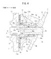
FIG. 4 is an essential part enlarged sectional view showing a lug plate, a movable body and the like, according to the compressor ofEmbodiment 1. -
FIG. 5 is a sectional view at a time of a minimum capacity in the compressor ofEmbodiment 1. -
FIG. 6 is a schematic view showing a state in which a guided surface abuts on a guide surface, and slides from a first abutment position to a second abutment position while being guided, according to the compressor ofEmbodiment 1. -
FIG. 7A is a schematic view showing a contact angle in a first abutment position of the guide surface and the guided surface, according to the compressor ofEmbodiment 1. -
FIG. 7B is a schematic view showing a contact angle in a second abutment position of the guide surface and the guided surface, according to the compressor ofEmbodiment 1. -
FIG. 8 is a graph showing a change ratio of a capacity increasing component, based on a change in a contact angle and a change in a variable differential pressure. -
FIG. 9 is a schematic view showing a state in which a guided surface abuts on a guide surface and slides from a first abutment position to a second abutment position while being guided, according to a compressor ofEmbodiment 2. -
FIG. 10 is a schematic view showing a contact angle of a guide surface and a guided surface, according to a compressor of a comparative example. - Hereinafter,
Embodiments Embodiments - As shown in
FIG. 1 , a compressor ofEmbodiment 1 includes ahousing 1, adrive shaft 3, aswash plate 5, alink mechanism 7, a plurality ofpistons 9, a pair ofshoes actuator 13, and acontrol mechanism 15 shown inFIG. 2 . - As shown in
FIG. 1 , thehousing 1 has afront housing 17 that is located at a front part of the compressor, arear housing 19 that is located at a rear part of the compressor, acylinder block 21 that is located between thefront housing 17 and therear housing 19, and avalve formation plate 23. - The
front housing 17 has afront wall 17a that extends in an up and down direction of the compressor in the front part, and acircumferential wall 17b that is integrated with thefront wall 17a and extends toward the rear part from the front part of the compressor. By thefront wall 17a and thecircumferential wall 17b, thefront housing 17 forms a substantially cylindrical shape with a bottom. Further, by thefront wall 17a and thecircumferential wall 17b, aswash plate chamber 25 is formed in thefront housing 17. - In the
front wall 17a, aboss 17c that protrudes forward is formed. In theboss 17c, ashaft seal device 27 is provided. Further, in theboss 17c, afirst shaft hole 17d that extends in a longitudinal direction of the compressor is formed. In thefirst shaft hole 17d, a first slidingbearing 29a is provided. - In the
circumferential wall 17b, aninlet port 250 that communicates with theswash plate chamber 25 is formed. Through theinlet port 250, theswash plate chamber 25 is connected to an evaporator not illustrated. Thereby, a low pressure refrigerant gas that has passed through the evaporator flows into theswash plate chamber 25 through theinlet port 250. Therefore, a pressure in theswash plate chamber 25 is lower than a pressure in adischarge chamber 35 that will be described later. - In the
rear housing 19, a part of thecontrol mechanism 15 is provided. Further, in therear housing 19, a firstpressure regulation chamber 31a, asuction chamber 33 and adischarge chamber 35 are formed. The firstpressure regulation chamber 31a is located in a center portion of therear housing 19. Thedischarge chamber 35 is located annularly at an outer circumferential side of therear housing 19. Further, thesuction chamber 33 is formed annularly between the firstpressure regulation chamber 31a and thedischarge chamber 35, in therear housing 19. Thedischarge chamber 35 is connected to an outlet port not illustrated. - In the
cylinder block 21, cylinder bores 21a, the number of which is the same as the number of thepistons 9, are formed in a circumferential direction at equiangular intervals. Front end sides of the respective cylinder bores 21a communicate with theswash plate chamber 25. Further, in thecylinder block 21, aretainer groove 21b that regulates a maximum angle of asuction reed valve 41a that will be described later is formed. - Furthermore, in the
cylinder block 21, asecond shaft hole 21c that extends in the longitudinal direction of the compressor while communicating with theswash plate chamber 25 is provided to penetrate thecylinder block 21. In thesecond shaft hole 21c, a second slidingbearing 29b is provided. Note that in place of the first slidingbearing 29a and the second sliding bearing 29b described above, rolling bearings can be adopted respectively. - Further, in the
cylinder block 21, aspring chamber 21d is formed. Thespring chamber 21d is located between theswash plate chamber 25 and thesecond shaft hole 21c. In thespring chamber 21d, areturn spring 37 is disposed. Thereturn spring 37 urges theswash plate 5 the inclination angle of which is minimum toward a front part of theswash plate chamber 25. Further, in thecylinder block 21, asuction passage 39 that communicates with theswash plate chamber 25 is formed. - The
valve formation plate 23 is provided between therear housing 19 and thecylinder block 21. Thevalve formation plate 23 consists of avalve plate 40, asuction valve plate 41, adischarge valve plate 43 and aretainer plate 45. - In the
valve plate 40, thedischarge valve plate 43 and theretainer plate 45,suction ports 40a the number of which is the same as the number of the cylinder bores 21a are formed. Further, in thevalve plate 40 and thesuction valve plate 41,discharge ports 40b the number of which is the same as the number of the cylinder bores 21a are formed. The respective cylinder bores 21a communicate with thesuction chamber 33 through therespective suction ports 40a, and communicate with thedischarge chamber 35 through therespective discharge ports 40b. Further, in thevalve plate 40, thesuction valve plate 41, thedischarge valve plate 43 and theretainer plate 45, afirst communication hole 40c and asecond communication hole 40d are formed. By thefirst communication hole 40c, thesuction chamber 33 and thesuction passage 39 communicate with each other. Thereby, theswash plate chamber 25 and thesuction chamber 33 communicate with each other. - The
suction valve plate 41 is provided on a front surface of thevalve plate 40. At thesuction valve plate 41, a plurality ofsuction reed valves 41a capable of opening and closing therespective suction ports 40a by elastic deformation are formed. Further, thedischarge valve plate 43 is provided on a rear surface of thevalve plate 40. At thedischarge valve plate 43, a plurality ofdischarge reed valves 43a capable of opening and closing therespective discharge ports 40b by elastic deformation are formed. Theretainer plate 45 is provided on a rear surface of thedischarge valve plate 43. Theretainer plate 45 restricts a maximum opening degree of thedischarge reed valve 43a. - The
drive shaft 3 is inserted toward a rear side of thehousing 1 from aboss 17c side. Thedrive shaft 3 has a front end side inserted through theshaft seal device 27 in theboss 17c, and supported by the first slidingbearing 29a in thefirst shaft hole 17d. Further, a rear end side of thedrive shaft 3 is supported by the second sliding bearing 29b in thesecond shaft hole 21c. In this manner, thedrive shaft 3 is supported rotatably around a drive shaft axis O with respect to thehousing 1. In thesecond shaft hole 21c, a secondpressure regulation chamber 31b is defined in a space from a rear end of thedrive shaft 3. The secondpressure regulation chamber 31b communicates with the firstpressure regulation chamber 31a through thesecond communication hole 40d. By these first and the secondpressure regulation chambers pressure regulation chamber 31 is formed. - At the rear end of the
drive shaft 3, O-rings rings drive shaft 3 and thesecond shaft hole 21c to seal a space between theswash plate chamber 25 and thepressure regulation chamber 31. - Further, the
link mechanism 7, theswash plate 5 and theactuator 13 are fitted to thedrive shaft 3. As shown inFIG. 3 , thelink mechanism 7 has alug plate 51, a pair oflug arms lug plate 51, and a pair ofswash plate arms swash plate 5. Thelug plate 51 corresponds to a lug member in the present invention. Note that inFIG. 3 , in order to facilitate explanation, shapes of thelug plate 51, theswash plate 5 and the like are illustrated by being simplified. - As shown in
FIG. 1 , thelug plate 51 is formed into a substantially annular ring shape in which aninsertion hole 510 is provided to penetrate therethrough. Thelug plate 51 is disposed forward of theswash plate 5, in theswash plate chamber 25. As shown inFIG. 4 , thedrive shaft 3 is press-fitted into theinsertion hole 510, and thelug plate 51 is rotatable integrally with thedrive shaft 3. Further, between thelug plate 51 and thefront wall 17a, athrust bearing 55 is provided. - In the
lug plate 51, acylindrical cylinder chamber 51a that extends in a longitudinal direction of thelug plate 51 is concavely provided coaxially with the drive shaft axis O. Thecylinder chamber 51a opens to theswash plate chamber 25 at a rear end surface of thelug plate 51, and extends to a spot to be an inner side of the thrust bearing 55 in thelug plate 51, from the rear end surface of thelug plate 51. - As shown in
FIG. 3 , therespective lug arms lug plate 51. Further, on thelug plate 51, a pair ofguide surfaces respective lug arms lug arms lug plate 51 such that a top dead center surface X, which is an imaginary surface defined by a top dead center position T of theswash plate 5 and the drive shaft axis O, is interposed therebetween. Further, in the compressor, a first virtual plane Y1 that intersects the drive shaft axis O while being orthogonal to the top dead center surface X is assumed. - As shown in
FIG. 1 , theswash plate 5 forms an annular flat plate shape, and has afront surface 5a and arear surface 5b. On thefront surface 5a, aweight portion 5c that protrudes forward of theswash plate 5 is formed. Theweight portion 5c abuts on thelug plate 51 when the inclination angle of theswash plate 5 becomes maximum. Further, in a center of theswash plate 5, aninsertion hole 5d is formed. Thedrive shaft 3 is inserted through theinsertion hole 5d. - As shown in
FIG. 3 , the respectiveswash plate arms front surface 5a of theswash plate 5 with the top dead center surface X therebetween. The respectiveswash plate arms front surface 5a. Further, at tip ends of the respectiveswash plate arms surfaces FIG. 4 , the guidedsurface 59a is formed into a cylindrical shape having a generating line that extends in a direction orthogonal to the top dead center surface X. The same goes for the guidedsurface 59b. - Further, as shown in
FIG. 1 , in theswash plate 5, a substantially semisphericalconvex portion 5g is protrudingly provided on thefront surface 5a, and is integrated with thefront surface 5a. Theconvex portion 5g is located between theswash plate arm 5e and theswash plate arm 5f. - As shown in
FIG. 3 , in the compressor, the respectiveswash plate arms respective lug arms lug plate 51 and theswash plate 5 are connected. Thereby, a rotational drive force of thelug plate 51 is transmitted to the respectiveswash plate arms respective lug arms swash plate 5 is rotatable with thelug plate 51, in theswash plate chamber 25. - As above, the
lug plate 51 and theswash plate 5 are connected, whereby the guidedsurface 59a of theswash plate arm 5e abuts on theguide surface 57a, and the guidedsurface 59b of theswash plate arm 5f abuts on theguide surface 57b. Here, the respective guidedsurfaces swash plate arms respective guide surfaces surfaces surfaces respective guide surfaces swash plate 5 can change an inclination angle of its own relative to a direction orthogonal to the drive shaft axis O, from a maximum inclination angle shown inFIG. 1 to a minimum inclination angle shown inFIG. 5 , while substantially keeping the top dead center position T. - As described above, the respective guided
surfaces surfaces FIG. 6 , in both a first abutment position P1 and a second abutment position P2, distances from respective centers C1 of the guidedsurfaces - As shown in
FIG.3 andFIG. 4 , theguide surface 57a extends outward in a radial direction of thelug plate 51 from the drive shaft axis O side. Theguide surface 57a is formed into a substantially cylindrical shape having a generating line that extends to be orthogonal to the top dead center surface X, and bends into a convex shape that protrudes rearward with respect to the first virtual plane Y1. More specifically, as shown inFIG. 6 , theguide surface 57a is formed such that a portion between the first abutment position P1, where theguide surface 57a and the guidedsurface 59a are in linear contact with each other when the inclination angle of theswash plate 5 is maximum, and the second abutment position P2, where theguide surface 57a and the guidedsurface 59a are in linear contact with each other when the inclination angle is minimum, is convex toward the guidedsurface 59a. Further, in theguide surface 57a, a top portion P3 is formed to be offset to the first abutment position P1 side from a middle between the first abutment position P1 and the second abutment position P2. The top portion P3 is present at a position that is the most separated from the first virtual plane Y1, in the generating line on theguide surface 57a. Theguide surface 57b shown inFIG. 3 is similar to the above, and is formed into a convex shape toward the guidedsurface 59b. - As shown in
FIG. 4 , theactuator 13 consists of thelug plate 51, amovable body 13a and acontrol pressure chamber 13b. - The
movable body 13a has thedrive shaft 3 inserted therethrough, and is movable in the drive shaft axis O direction while sliding in contact with thedrive shaft 3. Themovable body 13a forms a cylindrical shape coaxial with thedrive shaft 3. In more detail, themovable body 13a has afirst cylinder portion 131, asecond cylinder portion 132, and aconnection portion 133. Thefirst cylinder portion 131 is located at theswash plate 5 side in themovable body 13a, and is in sliding contact with thedrive shaft 3. An O-ring 49c is provided on an inner circumferential surface of thefirst cylinder portion 131. Thesecond cylinder portion 132 is located at a front part of themovable body 13a. Thesecond cylinder portion 132 is formed to have a larger diameter than thefirst cylinder portion 131. An O-ring 49d is provided on an outer circumferential surface of thesecond cylinder portion 132. Theconnection portion 133 is located between thefirst cylinder portion 131 and thesecond cylinder portion 132, and extends while gradually enlarging a diameter toward the front part from a rear part of themovable body 13a. In theconnection portion 133, a rear end continues to thefirst cylinder portion 131, and a front end continues to thesecond cylinder portion 132. - Further, an acting
portion 134 is formed integrally with a rear end of thefirst cylinder portion 131. The actingportion 134 vertically extends toward a top dead center position T side of theswash plate 5 from the drive shaft axis O side, and abuts on theconvex portion 5g. Thereby, themovable body 13a is rotatable integrally with thelug plate 51 and theswash plate 5. - Further, the
cylinder chamber 51a can accommodate thesecond cylinder portion 132 and theconnection portion 133 by causing thesecond cylinder portion 132 and theconnection portion 133 to advance to an inside. - The
control pressure chamber 13b is formed among thesecond cylinder portion 132, theconnection portion 133, thecylinder chamber 51a and thedrive shaft 3. A space between thecontrol pressure chamber 13b and theswash plate chamber 25 is sealed by the O-rings - Further, in the
drive shaft 3, anaxial path 3a that extends in the drive shaft axis O direction toward the front end from the rear end of thedrive shaft 3, and aradial path 3b that extends in a radial direction from a front end of theaxial path 3a and opens to the outer circumferential surface of thedrive shaft 3 are formed. As shown inFIG. 1 , a rear end of theaxial path 3a opens to thepressure regulation chamber 31. Meanwhile, theradial path 3b opens to thecontrol pressure chamber 13b. By theaxial path 3a and theradial path 3b, thepressure regulation chamber 31 and thecontrol pressure chamber 13b communicate with each other. - The
drive shaft 3 is connected to a pulley or an electromagnetic clutch not illustrated, by ascrew portion 3c that is formed at a tip end. - The
respective pistons 9 are respectively accommodated in the respective cylinder bores 21a, and are capable of reciprocating in the respective cylinder bores 21a. By therespective pistons 9 and thevalve formation plate 23,compression chambers 61 are defined in the respective cylinder bores 21a. - Further, in the
respective pistons 9, engagingportions 9a are concavely provided respectively. In the engagingportion 9a, thesemispherical shoes respective shoes swash plate 5 into reciprocal movement of therespective pistons 9. Therespective shoes respective pistons 9 can reciprocate in the cylinder bores 21a respectively at a stroke corresponding to the inclination angle of theswash plate 5. - As shown in
FIG. 2 , thecontrol mechanism 15 has a low-pressure passage 15a, a high-pressure passage 15b, acontrol valve 15c and anorifice 15d, and theaxial path 3a and theradial path 3b. - The low-
pressure passage 15a is connected to thepressure regulation chamber 31 and thesuction chamber 33. Thereby, by the low-pressure passage 15a, theaxial path 3a and theradial path 3b, thecontrol pressure chamber 13b, thepressure regulation chamber 31 and thesuction chamber 33 are brought into a state communicating to one another. The high-pressure passage 15b is connected to thepressure regulation chamber 31 and thedischarge chamber 35. By the high-pressure passage 15b, theaxial path 3a and theradial path 3b, thecontrol pressure chamber 13b, thepressure regulation chamber 31 and thedischarge chamber 35 communicate with one another. Further, theorifice 15d is provided in the high-pressure passage 15b. - The
control valve 15c is provided in the low-pressure passage 15a. Thecontrol valve 15c can regulate an opening degree of the low-pressure passage 15a based on a pressure in thesuction chamber 33. - In the compressor, piping connecting to the evaporator is connected to the
inlet port 250 shown inFIG. 1 , and piping connecting to a condenser is connected to the outlet port. The condenser is connected to the evaporator via piping and an expansion valve. By the compressor, the evaporator, the expansion valve, the condenser and the like, a refrigeration circuit of an air-conditioning apparatus for a vehicle is configured. Note that illustration of the evaporator, the expansion valve, the condenser and the respective pipings are omitted. - In the compressor which is configured as above, the
drive shaft 3 rotates, whereby theswash plate 5 rotates, and therespective pistons 9 reciprocate in the respective cylinder bores 21a. Therefore, thecompression chamber 61 changes a capacity in response to a piston stroke. Therefore, the refrigerant gas which is taken into theswash plate chamber 25 by theinlet port 250 from the evaporator passes through thesuction chamber 33 from thesuction passage 39 and is compressed in thecompression chamber 61. Subsequently, the refrigerant gas which is compressed in thecompression chamber 61 is discharged into thedischarge chamber 35 and is discharged into the condenser from the outlet port. Further, by theweight portion 5c, an inertial force during rotation of theswash plate 5 is regulated. - During the above, in the compressor, a piston compression force that makes the inclination angle of the
swash plate 5 small acts onto theswash plate 5, thelug plate 51 and the like. In the compressor, the inclination angle of theswash plate 5 is changed to increase or decrease the stroke of thepiston 9, and thereby capacity control can be performed. - More specifically, when the
control valve 15c shown inFIG. 2 makes the opening degree of the low-pressure passage 15a large, in thecontrol mechanism 15, the pressure in thepressure regulation chamber 31, and by extension, the pressure in thecontrol pressure chamber 13b becomes substantially equal to the pressure in thesuction chamber 33. Therefore, a differential pressure (hereinafter, called a variable differential pressure) between thecontrol pressure chamber 13b and theswash plate chamber 25 becomes small. Thereby, by the piston compression force which acts on theswash plate 5, in theactuator 13, themovable body 13a slides in thecylinder chamber 51a toward thelug plate 51 side from theswash plate 5 side in the drive shaft axis O direction, as shown inFIG. 1 . - Further, at the same time, in the compressor, by the piston compression force and the urging force of the
return spring 37 which act on theswash plate 5 itself, the guidedsurface 59a of theswash plate arm 5e slides on theguide surface 57a so as to be away from the drive shaft axis O. Similarly, the guidedsurface 59b of theswash plate arm 5f also slides on theguide surface 57b. - Therefore, in the
swash plate 5, a bottom dead center side pivots in a clockwise direction while substantially keeping the top dead center position T. In this manner, in the compressor, the inclination angle of theswash plate 5 to the drive shaft axis O of thedrive shaft 3 increases. Thereby, in the compressor, the stroke of thepiston 9 increases, and the discharge capacity per one rotation of thedrive shaft 3 becomes large. Note that the inclination angle of theswash plate 5 shown inFIG. 1 is a maximum inclination angle in the compressor. At this time, the guidedsurface 59a and theguide surface 57a are in linear contact with each other at the first position P1 as shown inFIG. 6 . The same applies to the guidedsurface 59b and theguide surface 57b. - Meanwhile, when the
control valve 15c shown inFIG. 2 makes the opening degree of the low-pressure passage 15a small, the pressure in thepressure regulation chamber 31 becomes high, and the pressure in thecontrol pressure chamber 13b becomes high. Therefore, the variable differential pressure becomes large. Thereby, as shown inFIG. 5 , themovable body 13a slides in thecylinder chamber 51a in the drive shaft axis O direction toward theswash plate 5 side while moving away from thelug plate 51. - Thereby, in the compressor, the acting
portion 134 presses theconvex portion 5g toward the rear part of theswash plate chamber 25. Therefore, the guidedsurface 59a of theswash plate arm 5e slides on theguide surface 57a so as to be close to the drive shaft axis O. Similarly, the guidedsurface 59b of theswash plate arm 5f also slides on theguide surface 57b. - Therefore, in the
swash plate 5, the bottom dead center side pivots in a counterclockwise direction while substantially keeping the top dead center position T. In this manner, in the compressor, the inclination angle of theswash plate 5 to the drive shaft axis O of thedrive shaft 3 is decreased. Thereby, in the compressor, the stroke of thepiston 9 decreases, and the discharge capacity per one rotation of thedrive shaft 3 becomes small. Further, theswash plate 5 abuts on thereturn spring 37 by the inclination angle decreasing. Note that the inclination angle of theswash plate 5 shown inFIG. 5 is a minimum inclination angle in the compressor. At this time, as shown inFIG. 6 , the guidedsurface 59a and theguide surface 57a are in linear contact with each other at the second position P2. The same applies to the guidedsurface 59b and theguide surface 57b. - As above, in the compressor, the respective guided
surfaces swash plate arms respective guide surfaces lug plate 51, whereby change of the inclination angle of theswash plate 5 is allowed. Here, in the compressor, the guide surfaces 57a and 57b are formed such that portions between the first abutment position P1 and the second abutment position P2 are convex toward the guidedsurfaces - The radius of curvature changes as above, and thereby, a contact angle θ1, which is an angle formed by the guide surfaces 57a and 57b and the guided
surfaces FIG. 7A , differs from a contact angle θ2, which is an angle formed by the guide surfaces 57a and 57b and the guidedsurfaces FIG. 7B in this compressor. Hereinafter, details will be described based on theguide surface 57a and the guidedsurface 59a. - The contact angle θ1 refers to an angle formed by a contact surface S1, which is formed by the
guide surface 57a and the guidedsurface 59a, and a second virtual plane Y2, which is a plane orthogonal to the drive shaft axis O, when the inclination angle of theswash plate 5 is maximum, i.e., at the first abutment position P1 as shown inFIG. 7A . Likewise, the contact angle θ2 refers to an angle formed by a contact surface S2, which is formed by theguide surface 57a and the guidedsurface 59a, and the second virtual plane Y2, which is a plane orthogonal to the drive shaft axis O, when the inclination angle of theswash plate 5 is minimum, i.e., at the second abutment position P2 as shown inFIG. 7B . -
FIG. 10 shows a compressor of a comparative example. In the compressor of the comparative example, a pair of guide surfaces 63 are formed on thelug plate 51. The respective guide surfaces 63 are formed to be flat downward inclinations toward a center side from an outer circumferential side of thelug plate 51 along the first virtual plane Y1. Thereby, in the compressor, a radius of curvature is fixed from the first abutment position P1 to the second abutment position P2. Therefore, either in the first abutment position P1, or in the second abutment position P2, contact angles θx of the respective guidedsurfaces - In this respect, in the present compressor, the radius of curvature is large at the first abutment position P1 side, and the radius of curvature is small at the second abutment position P2 side. Therefore, in this compressor, the contact angle changes from the contact angle θ1 to the contact angle θ2 while the inclination angle becomes minimum from the maximum.
- As shown in a graph in
FIG. 8 , in the compressor, as the radius of curvature becomes larger, and the contact angle of the guide surfaces 57a and 57b and the guidedsurfaces surfaces - Here, in this compressor, the contact angle θ1 in the first abutment position P1 is an angle that is larger than the contact angle θx in the compressor of the comparative example. Meanwhile, the contact angle θ2 in the second abutment position P2 is an angle that is smaller than the contact angle θx in the compressor of the comparative example.
- Thereby, in this compressor, the capacity increasing component can be made large when the inclination angle of the
swash plate 5 is maximum, and the maximum discharge capacity is easily kept, as compared with the compressor of the comparative example. Conversely, in this compressor, the capacity increasing component can be made small when the inclination angle of theswash plate 5 is minimum, and the minimum discharge capacity can be easily kept. Meanwhile, in the compressor of the comparative example, the radius of curvature is fixed, and therefore, the capacity increasing component is fixed when the inclination angle of theswash plate 5 is maximum and when the inclination angle is minimum. Therefore, the maximum discharge capacity and the minimum discharge capacity are difficult to keep. - Consequently, according to the compressor of
Embodiment 1, in the compressor which changes the discharge capacity by theactuator 13, the maximum discharge capacity can be favorably kept and the minimum discharge capacity also can be favorably kept. - In particular, in this compressor, the top portions P3 of the guide surfaces 57a and 57b are offset to the first abutment position P1 side from the middle between the first abutment position P1 and the second abutment position P2. Therefore, in this compressor, in changing the inclination angle of the
swash plate 5, the respective guidedsurfaces respective guide surfaces - A compressor in
Embodiment 2 is provided with a pair ofswash plate arms 67 shown inFIG. 9 , in place of theswash plate arms Embodiment 1. Though not illustrated, the respectiveswash plate arms 67 are also respectively formed on thefront surface 5a of theswash plate 5 with the top dead center surface X interposed therebetween, and extend forward from thefront surface 5a. Further, guidedsurfaces 67a are formed at tip ends of the respectiveswash plate arms 67. As shown by the two-dot chain lines inFIG. 9 , the guidedsurface 67a is formed into an elliptical shape having a generating line that extends to be orthogonal to the top dead center surface X. - Thereby, in the compressor, a radius R1 of curvature of the
guide surface 67a at the first abutment position P1 differs from a radius R2 of curvature of theguide surface 67a at the second abutment position P2. More specifically, the radius R1 of curvature of the guidedsurface 67a in the first abutment position P1 is smaller than the radius R2 of curvature of the guidedsurface 67a in the second abutment position P2. Note that the guidedsurface 67a may be formed into a parabolic shape or the like so that the radius of curvature of the guidedsurface 67a differs in the first abutment position P1 and the second abutment position P2. The other components in the compressor are similar to those in the compressor ofEmbodiment 1, and detailed explanation concerning the same components will be omitted by assigning the same reference sings to the same components. - In this compressor, the
guide surface 57a and the guidedsurface 67a are in linear contact with each other at a contact angle θ3 when an angle formed by a contact surface S3 of theguide surface 57a and the guidedsurface 67a and a second virtual plane Y2 at the first abutment position P1, i.e., the inclination angle of theswash plate 5, is maximum. Meanwhile, theguide surface 57a and the guidedsurface 67a are in linear contact with each other at a contact angle θ4 when an angle formed by a contact surface S4 of theguide surface 57a and the guidedsurface 67a and the second virtual plane Y2 at the second abutment position P2, i.e., the inclination angle of theswash plate 5, is minimum. As described above, in the guide surfaces 57a and 57b, the radiuses of curvature are large on the side of the first abutment position P1 side, and the radiuses of curvature are small on the side of the second abutment position P2. Therefore, in this compressor, the contact angle θ3 is larger than the contact angle θ4. - Here, as described above, the radius R1 of curvature of the guided
surface 67a at the first abutment position P1 is smaller than the radius R2 of curvature at the second abutment position P2. Therefore, in this compressor, at the first abutment position P1, a distance from the center C2 of the guidedsurface 67a to theguide surface 57a is short, and conversely, in the second abutment positionP2, the distance from the center C2 of the guidedsurface 67a to theguide surface 57a is long. - Thereby, even though the contact angles θ3 and θ4 differ from each other when the inclination angle of the
swash plate 5 is maximum and when the inclination angle is minimum, change of the top dead center position of thepiston 9 can be made small, in this compressor. The other operations in the compressor are similar to those of the compressor inEmbodiment 1. - Although the present invention has been described above based on
Embodiments - For example, with respect to the
control mechanism 15, thecontrol valve 15c may be provided in the high-pressure passage 15b, and theorifice 15d may be provided in the low-pressure passage 15a. In this case, the opening degree of the high-pressure passage 15b can be regulated by thecontrol valve 15c. Thereby, the pressure in thecontrol pressure chamber 13b can be made quickly high due to the pressure of the refrigerant gas in thefirst discharge chamber 29a, and the discharge capacity can be increased quickly. - In the compressor of the present invention, guide surfaces 57a and 57b are formed on a
lug plate 51 and guidedsurfaces swash plate arms surfaces surfaces
Claims (3)
- A variable displacement swash plate type compressor comprising:a housing (1) in which a suction chamber (33), a discharge chamber (35), a swash plate chamber (25) and a cylinder bore (21a) are formed;a drive shaft (3) that is rotatably supported by the housing (1);a swash plate (5) rotatable in the swash plate chamber (25) by rotation of the drive shaft (3);a link mechanism (7) that is provided between the drive shaft (3) and the swash plate (5) and allows change of an inclination angle of the swash plate (5) to a direction orthogonal to a drive shaft axis (O) of the drive shaft (3);a piston (9) that is accommodated in the cylinder bore (21a) to be capable of reciprocating;a conversion mechanism (11a, 11b) that causes the piston (9) to reciprocate in the cylinder bore (21a) at a stroke corresponding to the inclination angle by rotation of the swash plate (5);an actuator (13) capable of changing the inclination angle; anda control mechanism (15) that controls the actuator (13),wherein the link mechanism (7) has a lug member (51) that is provided on the drive shaft (3) in the swash plate chamber (25) and faces the swash plate (5), and a swash plate arm (5e, 5f, 67) to which rotation of the drive shaft (3) is transmitted from the lug member (51),on the lug member (51), a guide surface (57a, 57b, 65) that faces the swash plate arm (5e, 5f, 67) is formed,on the swash plate arm (5e, 5f, 67), a guided surface (59a, 59b, 67a) that abuts on and is guided by the guide surface (57a, 57b, 65) is formed,the actuator (13) has the lug member (51), a movable body (13a) that is disposed between the lug member (51) and the swash plate (5) and is movable in a direction of the drive shaft axis (O), and a control pressure chamber (13b) that is provided between the lug member (51) and the movable body (13a) and moves the movable body (13a) by an internal pressure, andthe guide surface (57a, 57b, 65) is formed such that a portion thereof between a first abutment position (P1), where the guided surface (57a, 57b, 65) abuts on the guide surface (57a, 57b, 65) when the inclination angle is maximum, and a second abutment position (P2), where the guided surface (59a, 59b, 67a) abuts on the guide surface (57a, 57b, 65) when the inclination angle is minimum, is convex toward the guided surface (59a, 59b, 67a).
- The variable displacement swash plate type compressor according to claim 1,
wherein a top portion (P3) of the guide surface (57a, 57b, 65) is offset to the first abutment position (P1) side from a middle of the first abutment position (P1) and the second abutment position (P2). - The variable displacement swash plate type compressor according to claim 1 or 2,
wherein a radius of curvature (R1, R2) of the guided surface (59a, 59b, 67a) differs between the first abutment position (P1) and the second abutment position (P2).
Applications Claiming Priority (1)
| Application Number | Priority Date | Filing Date | Title |
|---|---|---|---|
| JP2014061850A JP6201852B2 (en) | 2014-03-25 | 2014-03-25 | Variable capacity swash plate compressor |
Publications (2)
| Publication Number | Publication Date |
|---|---|
| EP2927492A2 true EP2927492A2 (en) | 2015-10-07 |
| EP2927492A3 EP2927492A3 (en) | 2015-12-02 |
Family
ID=52577667
Family Applications (1)
| Application Number | Title | Priority Date | Filing Date |
|---|---|---|---|
| EP15155907.7A Withdrawn EP2927492A3 (en) | 2014-03-25 | 2015-02-20 | Variable displacement swash plate type compressor |
Country Status (5)
| Country | Link |
|---|---|
| US (1) | US20150275871A1 (en) |
| EP (1) | EP2927492A3 (en) |
| JP (1) | JP6201852B2 (en) |
| KR (1) | KR101710929B1 (en) |
| CN (1) | CN104948414B (en) |
Families Citing this family (2)
| Publication number | Priority date | Publication date | Assignee | Title |
|---|---|---|---|---|
| JP6094456B2 (en) * | 2013-10-31 | 2017-03-15 | 株式会社豊田自動織機 | Variable capacity swash plate compressor |
| DE102019112237A1 (en) * | 2019-04-12 | 2020-10-15 | OET GmbH | Reciprocating compressor |
Citations (1)
| Publication number | Priority date | Publication date | Assignee | Title |
|---|---|---|---|---|
| JPH08105384A (en) | 1994-10-05 | 1996-04-23 | Sanden Corp | Variable displacement swash plate type compressor |
Family Cites Families (13)
| Publication number | Priority date | Publication date | Assignee | Title |
|---|---|---|---|---|
| US4037993A (en) * | 1976-04-23 | 1977-07-26 | Borg-Warner Corporation | Control system for variable displacement compressor |
| US4061443A (en) * | 1976-12-02 | 1977-12-06 | General Motors Corporation | Variable stroke compressor |
| US4553905A (en) * | 1984-05-09 | 1985-11-19 | Diesel Kiki Co., Ltd. | Variable capacity wobble plate compressor with high stability of capacity control |
| JPH0814159A (en) * | 1994-06-27 | 1996-01-16 | Sanden Corp | Cam plate type variable capacity compressor |
| JP2001032768A (en) * | 1999-07-19 | 2001-02-06 | Zexel Valeo Climate Control Corp | Variable displacement swash plate compressor |
| JP2003254231A (en) * | 2001-12-25 | 2003-09-10 | Toyota Industries Corp | Variable displacement compressor |
| JP4062265B2 (en) * | 2004-02-24 | 2008-03-19 | 株式会社豊田自動織機 | Variable capacity compressor |
| JP2006009626A (en) * | 2004-06-23 | 2006-01-12 | Toyota Industries Corp | Variable displacement compressor |
| JP4150982B2 (en) * | 2006-10-31 | 2008-09-17 | 東洋紡績株式会社 | Laminated film and adhesive modified substrate film for obtaining the same |
| JP2009209910A (en) * | 2008-03-06 | 2009-09-17 | Toyota Industries Corp | Swash plate compressor |
| JP5519193B2 (en) * | 2009-06-05 | 2014-06-11 | サンデン株式会社 | Variable capacity compressor |
| KR101193399B1 (en) * | 2012-06-22 | 2012-10-26 | 주식회사 두원전자 | Variable displacement swash plate type compressor |
| KR20140004367A (en) * | 2012-07-02 | 2014-01-13 | 학교법인 두원학원 | Variable displacement swash plate type compressor |
-
2014
- 2014-03-25 JP JP2014061850A patent/JP6201852B2/en not_active Expired - Fee Related
-
2015
- 2015-02-20 EP EP15155907.7A patent/EP2927492A3/en not_active Withdrawn
- 2015-02-27 US US14/633,371 patent/US20150275871A1/en not_active Abandoned
- 2015-03-13 KR KR1020150035059A patent/KR101710929B1/en not_active Expired - Fee Related
- 2015-03-23 CN CN201510127243.6A patent/CN104948414B/en not_active Expired - Fee Related
Patent Citations (1)
| Publication number | Priority date | Publication date | Assignee | Title |
|---|---|---|---|---|
| JPH08105384A (en) | 1994-10-05 | 1996-04-23 | Sanden Corp | Variable displacement swash plate type compressor |
Also Published As
| Publication number | Publication date |
|---|---|
| JP2015183616A (en) | 2015-10-22 |
| CN104948414A (en) | 2015-09-30 |
| CN104948414B (en) | 2017-04-12 |
| EP2927492A3 (en) | 2015-12-02 |
| KR101710929B1 (en) | 2017-02-28 |
| KR20150111285A (en) | 2015-10-05 |
| JP6201852B2 (en) | 2017-09-27 |
| US20150275871A1 (en) | 2015-10-01 |
Similar Documents
| Publication | Publication Date | Title |
|---|---|---|
| KR101659812B1 (en) | Variable displacement swash plate type compressor | |
| EP2784316A1 (en) | Variable displacement swash plate compressor | |
| EP2728182A2 (en) | Swash plate type variable displacement compressor | |
| EP2728183A2 (en) | Swash plate type variable displacement compressor | |
| CN104712528B (en) | Variable displacement swash plate type compressor | |
| EP2924287B1 (en) | Variable displacement swash plate type compressor | |
| KR101603439B1 (en) | Swash plate type variable displacement compressor | |
| US20150260175A1 (en) | Variable displacement swash plate type compressor | |
| EP3026265B1 (en) | Variable displacement swash-plate compressor | |
| KR101796406B1 (en) | Variable-displacement swash-plate-type compressor | |
| US20150275871A1 (en) | Variable displacement swash plate type compressor | |
| US9915252B2 (en) | Variable displacement swash plate compressor having a fulcrum and an action point located on opposite sides of a drive shaft | |
| EP3029321B1 (en) | Variable displacement swash-plate compressor | |
| EP3026264B1 (en) | Variable displacement swash-plate compressor | |
| US9903354B2 (en) | Variable displacement swash plate compressor | |
| EP2944814A2 (en) | Variable displacement swash plate compressor | |
| US20150275877A1 (en) | Variable displacement swash plate compressor |
Legal Events
| Date | Code | Title | Description |
|---|---|---|---|
| PUAI | Public reference made under article 153(3) epc to a published international application that has entered the european phase |
Free format text: ORIGINAL CODE: 0009012 |
|
| 17P | Request for examination filed |
Effective date: 20150220 |
|
| AK | Designated contracting states |
Kind code of ref document: A2 Designated state(s): AL AT BE BG CH CY CZ DE DK EE ES FI FR GB GR HR HU IE IS IT LI LT LU LV MC MK MT NL NO PL PT RO RS SE SI SK SM TR |
|
| AX | Request for extension of the european patent |
Extension state: BA ME |
|
| PUAL | Search report despatched |
Free format text: ORIGINAL CODE: 0009013 |
|
| AK | Designated contracting states |
Kind code of ref document: A3 Designated state(s): AL AT BE BG CH CY CZ DE DK EE ES FI FR GB GR HR HU IE IS IT LI LT LU LV MC MK MT NL NO PL PT RO RS SE SI SK SM TR |
|
| AX | Request for extension of the european patent |
Extension state: BA ME |
|
| RIC1 | Information provided on ipc code assigned before grant |
Ipc: F04B 27/10 20060101AFI20151023BHEP Ipc: F04B 27/18 20060101ALI20151023BHEP |
|
| STAA | Information on the status of an ep patent application or granted ep patent |
Free format text: STATUS: THE APPLICATION HAS BEEN WITHDRAWN |
|
| 18W | Application withdrawn |
Effective date: 20180306 |