EP2927465A1 - Method for determining the instantaneous mass flow rate of a gas, corresponding device and computer program - Google Patents
Method for determining the instantaneous mass flow rate of a gas, corresponding device and computer program Download PDFInfo
- Publication number
- EP2927465A1 EP2927465A1 EP14290092.7A EP14290092A EP2927465A1 EP 2927465 A1 EP2927465 A1 EP 2927465A1 EP 14290092 A EP14290092 A EP 14290092A EP 2927465 A1 EP2927465 A1 EP 2927465A1
- Authority
- EP
- European Patent Office
- Prior art keywords
- mass flow
- frequency spectrum
- time
- pressure
- conduit
- Prior art date
- Legal status (The legal status is an assumption and is not a legal conclusion. Google has not performed a legal analysis and makes no representation as to the accuracy of the status listed.)
- Granted
Links
Images


Classifications
-
- F—MECHANICAL ENGINEERING; LIGHTING; HEATING; WEAPONS; BLASTING
- F02—COMBUSTION ENGINES; HOT-GAS OR COMBUSTION-PRODUCT ENGINE PLANTS
- F02D—CONTROLLING COMBUSTION ENGINES
- F02D41/00—Electrical control of supply of combustible mixture or its constituents
- F02D41/02—Circuit arrangements for generating control signals
- F02D41/18—Circuit arrangements for generating control signals by measuring intake air flow
-
- G—PHYSICS
- G01—MEASURING; TESTING
- G01F—MEASURING VOLUME, VOLUME FLOW, MASS FLOW OR LIQUID LEVEL; METERING BY VOLUME
- G01F1/00—Measuring the volume flow or mass flow of fluid or fluent solid material wherein the fluid passes through a meter in a continuous flow
- G01F1/05—Measuring the volume flow or mass flow of fluid or fluent solid material wherein the fluid passes through a meter in a continuous flow by using mechanical effects
- G01F1/34—Measuring the volume flow or mass flow of fluid or fluent solid material wherein the fluid passes through a meter in a continuous flow by using mechanical effects by measuring pressure or differential pressure
-
- G—PHYSICS
- G01—MEASURING; TESTING
- G01F—MEASURING VOLUME, VOLUME FLOW, MASS FLOW OR LIQUID LEVEL; METERING BY VOLUME
- G01F1/00—Measuring the volume flow or mass flow of fluid or fluent solid material wherein the fluid passes through a meter in a continuous flow
- G01F1/66—Measuring the volume flow or mass flow of fluid or fluent solid material wherein the fluid passes through a meter in a continuous flow by measuring frequency, phase shift or propagation time of electromagnetic or other waves, e.g. using ultrasonic flowmeters
- G01F1/666—Measuring the volume flow or mass flow of fluid or fluent solid material wherein the fluid passes through a meter in a continuous flow by measuring frequency, phase shift or propagation time of electromagnetic or other waves, e.g. using ultrasonic flowmeters by detecting noise and sounds generated by the flowing fluid
-
- G—PHYSICS
- G01—MEASURING; TESTING
- G01F—MEASURING VOLUME, VOLUME FLOW, MASS FLOW OR LIQUID LEVEL; METERING BY VOLUME
- G01F1/00—Measuring the volume flow or mass flow of fluid or fluent solid material wherein the fluid passes through a meter in a continuous flow
- G01F1/72—Devices for measuring pulsing fluid flows
-
- G—PHYSICS
- G01—MEASURING; TESTING
- G01F—MEASURING VOLUME, VOLUME FLOW, MASS FLOW OR LIQUID LEVEL; METERING BY VOLUME
- G01F1/00—Measuring the volume flow or mass flow of fluid or fluent solid material wherein the fluid passes through a meter in a continuous flow
- G01F1/76—Devices for measuring mass flow of a fluid or a fluent solid material
-
- F—MECHANICAL ENGINEERING; LIGHTING; HEATING; WEAPONS; BLASTING
- F02—COMBUSTION ENGINES; HOT-GAS OR COMBUSTION-PRODUCT ENGINE PLANTS
- F02D—CONTROLLING COMBUSTION ENGINES
- F02D41/00—Electrical control of supply of combustible mixture or its constituents
- F02D41/24—Electrical control of supply of combustible mixture or its constituents characterised by the use of digital means
- F02D41/26—Electrical control of supply of combustible mixture or its constituents characterised by the use of digital means using computer, e.g. microprocessor
- F02D41/28—Interface circuits
- F02D2041/286—Interface circuits comprising means for signal processing
- F02D2041/288—Interface circuits comprising means for signal processing for performing a transformation into the frequency domain, e.g. Fourier transformation
-
- F—MECHANICAL ENGINEERING; LIGHTING; HEATING; WEAPONS; BLASTING
- F02—COMBUSTION ENGINES; HOT-GAS OR COMBUSTION-PRODUCT ENGINE PLANTS
- F02D—CONTROLLING COMBUSTION ENGINES
- F02D2200/00—Input parameters for engine control
- F02D2200/02—Input parameters for engine control the parameters being related to the engine
- F02D2200/04—Engine intake system parameters
- F02D2200/0402—Engine intake system parameters the parameter being determined by using a model of the engine intake or its components
Definitions
- the present invention relates to a method for determining the instantaneous mass flow rate of a gas, such as air, in a conduit.
- the invention also relates to an apparatus, and a computer program, arranged to conduct the method of the invention.
- air mass flow rate can be determined by using measurement devices, the measured air mass flow rate being used, for instance, by the engine control unit (ECU) to balance and deliver the correct fuel mass to the engine.
- ECU engine control unit
- the mass flow rate is represented as the ratio of a volume of air flowing through a predetermined sectional area of an air flow channel, i.e. a pipe, with respect to time.
- An example of such a measurement device is the hot-wire anemometer that uses a Wheatstone bridge to measure the mass flow rate.
- the resistance of the hot-wire varies according to the amount of air passing through the pipe, and this change of resistance is interpreted as a voltage and converted to mass flow information.
- Such a device is often used to give mean value information or an information once every engine cycle for example.
- this device is not designed to measure instantaneous (i.e. real time) values of the mass flow rate and often suffers from fragility due to the fact that the hot-wire is very thin and can easily break when exposed to the pulsating flow of an engine.
- the device comprises a fluid flow member provided with at least two wall pressure sensors, means to measure pressure difference coupled with the two pressure sensors, and programmed computing means to compute the flow rate in real-time by solving a nonlinear, ordinary differential equation which relates instant flow rate to pressure difference.
- the flow member comprises a filter positioned between the two pressure taps to increase pressure loss or difference between the two pressure taps.
- a disadvantage of such a solution is that it uses a filter in the flow path that disrupts the fluid flow to varying degrees.
- a further disadvantage is that the device relies on time domain analysis, meaning that it uses mean values of the measurement to solve differential equations. In order to do so, these equations are often simplified with a wide number of assumptions. Thus, the computed flow rate is rather inaccurate.
- time domain analysis for mass flow measurement is related to pressure difference measurements between two distinct points.
- Another way to measure air velocity is by using acoustic linear analytical transfer matrices.
- the purpose of the present invention is to remedy these drawbacks by proposing a method for determining the instantaneous mass flow of a gas, such as air in a conduit, like an air intake channel of an internal combustion engine of a motor vehicle, said method comprising the steps of: ⁇
- such method further comprises the steps of :
- the proposed mass flow measurement method is dedicated to steady and unsteady mass flow conditions.
- It may be used for instance to measure in real-time the unsteady mass flow in the air intake channel of an internal combustion engine, in which it is well-known that the direction of air mass flow varies.
- the method of the invention provides a real-time determination of the air mass which is more accurate than the prior art techniques, and requires less computing resources.
- the method implements a frequency-based approach and thus does not solve a differential equation model in the time domain as in the prior art.
- a model linking two pressure measurements at two points of an intake channel to instantaneous mass flow at each of these points is identified in the frequency domain, experimentally or by a simulation technique.
- the dynamic or unsteady pressure component (thus, not the mean value) is used to determine the dynamic mass flow component.
- the calculations are carried out in the frequency domain then brought back to the time domain to be viewed.
- said model is a transfer matrix
- the method of the invention implements a model description of the pulsation phenomena of the air mass flow and a transfer matrix in the frequency domain.
- the model takes the form of an algebraic transfer matrix similar in its writing to acoustic matrices.
- the step of obtaining the frequency spectrum of the mass flow at each of said measurement points consists in solving a frequency-domain linear equation determined from said model.
- the transfer matrix can be used to determine the mass flow rate anywhere in the intake line, and in any engine configuration.
- said transfer matrix is derived experimentally by measuring pressure response inside a given conduit after a mass flow excitation.
- the transfer matrix is identified and calibrated on a dynamic flow bench.
- such a method further comprises the steps of developing an engine control command as a function of the computed time-domain signal of the mass flow rate at any measurement point and controlling engine operation in accordance with the developed control command.
- the frequency spectrum of each of the measured pressure signals is obtained using a Fast Fourier Transform.
- the time-domain signal of the mass flow rate at any measurement point is obtained using an inverse Fast Fourier Transform.
- the invention also relates to a device for determining the instantaneous mass flow of a gas, such as air, in a conduit, like an air intake channel of an internal combustion engine of a motor vehicle, said device comprising:
- such device further comprises:
- the air mass flow estimator of the invention is accurate and requires no tuning or calibration.
- It comprises signal processing means which process time domain information of the two pressure measurements by accessing their respective frequency spectrum, and means for calculating (by solving frequency domain linear equations) the instantaneous mass flow using a calibration matrix obtained in advance relating the frequency spectrum of the latter to that of the measured pressures.
- the instantaneous mass flow is obtained by transposing the frequency spectrum of the mass flow (i.e. the representation of the mass flow signal in the frequency domain) to the time domain.
- said device comprises means for developing an engine control command as a function of the computed time-domain signal of the mass flow rate at any measurement point and ⁇ means for controlling engine operation in accordance with the developed control command.
- the means for measuring the time-domain signals of the gas pressure at said measurement points comprises two pressure sensors flush-mounted within the conduit
- the mass flow measurement method of the invention is non intrusive, i.e. there is no change in section between the two pressure sensors.
- the invention also relates to a computer program recorded on a computer-readable medium and capable of being run by a processor, the program including program code instructions for implementing the method of the invention.
- the intake manifold comprises a main intake duct referred to as a "plenum" and a plurality of runners or conduits that distribute airflow from the plenum to the intake ports of each cylinder of the engine.
- the intake port of each cylinder comprises at least one intake valve and a fuel injector allowing when the intake valve is opened an air/fuel mixture to be introduced into the corresponding combustion chamber of the engine.
- the intake valve shuts during the compression phase of the air/fuel mixture in the combustion chamber where it is combusted to drive pistons producing drive torque.
- Figure 1 shows the main intake duct or plenum 11 of the intake manifold from which open out a series of intake runners which are each associated with one of the cylinders of the engine. For reasons of clarity, only one conduit 12 and the intake valves of the cylinder heads are shown, in particular the intake valve 13 of conduit 12.
- the rapid motion (i.e. opening and closing) of the intake valve 13 are the source of pressure and mass flow variations in the conduit 12 which is of constant diameter.
- the engine performance (power and torque for instance), fuel consumption and emission levels are highly dependent on wave action created by the motion of the valves within the conduits.
- the method of the invention aims at measuring mass flow variations/dynamics in order to improve engine torque response, fuel consumption and overall volumetric efficiency.
- a control device 50 is provided which is capable of determining mass airflow in the conduit 12.
- the control device 50 which is arranged to conduct the method of the invention includes a control unit 52 which preferably comprises a microprocessor, a read only memory (ROM) 51 storing various operating steps and a transfer matrix, and a random-access memory (RAM) 54 used by the control unit 52 to store and retrieve data.
- a control unit 52 which preferably comprises a microprocessor, a read only memory (ROM) 51 storing various operating steps and a transfer matrix, and a random-access memory (RAM) 54 used by the control unit 52 to store and retrieve data.
- ROM read only memory
- RAM random-access memory
- the transfer matrix is determined in advance experimentally by means of tests using a dedicated or an appropriate test bench test bench, e.g. an engine test bench, or by means of simulation, and stored in the ROM 51.
- control device 50 regulates engine operations based on several inputs, in particular the pressure signals (or values) measured by the pressure sensors 21, 22 located at two distinct points A and B respectively of the conduit 12.
- the pressure sensors 21, 22 are located near the intake valve 13 and are less than 100 mm apart, the internal diameter of the conduit 12 being 30 mm in this example.
- the control unit 52 is thus arranged to receive inputs (i.e. measured values of the pressure) from the pressure sensors 21, 22 via the input/output (I/O) port 53.
- control unit 52 is capable of determining air mass flow at any of the points A and B of the conduit 12.
- a precise value of the mass flow in the conduit 12 is consequently provided in real-time by the control unit 52.
- the value(s) of the determined mass flow can then be used as control signals for actuators of the internal combustion engine, or also for diagnosis purposes.
- control unit 52 processes the pressure signals according to the method of the invention, whose steps will be described below, in order to obtain mass flow signals which may be used to generate at least one command signal based thereon.
- control device 50 may provide an output signal via the input/output port (I/O) 53 to control accurately the opening of the intake valves (intake valve timing), and thus improving volumetric efficency. Furthermore the knowledge of the instantaneous airflow allows to maintain a desired air-fuel ratio which is important to achieve optimal engine performance, fuel economy, and engine emissions.
- the opening of the intake valve may be timed to feed more air into the cylinder.
- the pressure sensors 21, 22 are located near the intake valve 13 to control the mass air flow entering the corresponding cylinder.
- the pressure sensors 21, 22 could be located at some other locations in the air circuit of the motor vehicle, near the air filter for instance. They could also be located upstream of the turbocharger for diagnosis purpose for instance.
- the real-time measurement device of the invention comprises two sensors 21, 22 mounted flush against the walls of the conduit 12, the sensors 21, 22 providing two measurements of static pressure at points A and B respectively (steps 81 and 82).
- the mass flow meter comprises the control device 50.
- the control unit 52 comprises signal processing means which process time domain information of the two pressure measurements by accessing their respective frequency spectrum (step 83), and means for calculating the instantaneous mass flow at points A and B (step 85) using linear equations relating the frequency spectrum of the mass flows to that of the measured pressures (step 84), the linear equations being derived from a calibration or transfer matrix obtained in advance (as mentioned previously).
- Any of the mass flow signals may be processed (step 86) to generate at least one command signal (step 87) based thereon.
- the one-dimensional plane wave theory with standing wave action flows allows to linearize the pressure and mass flow variables in the frequency domain and design transfer matrices having as coefficients U, V, W and X linking the information upstream (point A) to that downstream (point B).
- An appropriate signal processing allows retrieving time series data of mass flow in the time domain qm A .
- the two pressure sensors 21, 22 are used to measure the pressure at two distinct points A and B of the pipe or conduit 12, and then the two measurements are used to calculate the mass flow at any of the measurement points A and B.
- the dynamic mass flow rate i.e. the fluctuating mass flow around a certain mean value is calculated using the pressure signals. Also, unlike the prior art teachings, it is not required to calculate the pressure difference between the points A and B.
- the pressure signals are transposed to the frequency domain (step 84) using a Fast Fourier Transform (FFT).
- FFT Fast Fourier Transform
- the mass flow time domain values are obtained from the mass flow spectrum with an inverse Fast Fourier Transform (step 85)
- the device being designed to predict a mass flow for an engine and the signals being generally low frequency signals between 30 Hz and 200 Hz for fast running engines, the frequency range used is chosen between 0 and 1000 Hz.
- the solution of the invention measures the dynamic part of the mass flow, i.e. concentrates on the dynamic part using linear equations as above.
- the solution of the invention is non-intrusive since the pressure sensors 21, 22 are mounted flush within the conduit 12 and does not change the geometry (cross-section or length) of the conduit.
- the accurancy of the measurements depends on the sample frequency of the pressure sensors 21, 22.
- the coefficients U, V, W and X are calculated for a given tube geometry and are obtained after pressure measurements on a dynamic flow bench. These coefficients are a mix of gas dynamics, linear acoustic plane wave theory, signal processing and calibration.
- Each coefficient is measured for a given tube geometry (95 mm of length and 30 mm of internal diameter for instance).
- the "shock tube” technique is a technique where a tube is rigidly closed at one end and where an elastic membrane plugs the open end.
- the tube is connected to a vacuum pump. Once the desired level of vacuum is reached inside the tube, the elastic membrane is pierced and a shock wave propagates inside the tube. This causes important perturbations in pressure and mass flow. The pressure oscillations are recorded using pressure sensors.
- the inventors used another measurement technique implementing a device called a dynamic flow bench.
- This part can be any intake element, from simple pipes to elaborate intake systems (manifold, runners and pipes).
- it is a simple tube 40 which is represented schematically on the dynamic flow bench 60 in Figure 2 .
- the dynamic flow bench principle is to first create a steady mass flow inside the tube 40. This is done using a Superflow (registered trademark) industrial pump, air being aspirated at the upper open end 42 of the tube 40.
- Superflow registered trademark
- the mass flow is extinguished abruptly. This is done in approximately 0.5 ms using a hydraulic actuator that closes a guillotine located at the lower end 41 of the tube 40 and restricts the passage of the air. For example, the mass flow is extinguished from an initial value of 150 kg/h to zero in 0.5 ms.
- the bench 60 itself is equipped with a steady air mass sensor that enables the measurement of the initial desired mass flow, and the hydraulic guillotine is controlled via a computer interface.
- the mounted part is a simple tube 40 having an overall length of 252.5 mm and an internal diameter of 30 mm.
- This tube 40 is equipped with three pressure sensors 70, 71, 72 located at three distinct locations 0, 1 and 2 respectively of the tube 40 as shown in Figure 2 .
- the distance between the lower end 41 of the tube 40 and points 0, 1 and 2 is 45 mm, 112,5 mm and 207,5 mm respectively.
- This transfer matrix is then used on an engine to calculate the instantaneous mass flow using a pair of pressure sensors, according to the method described previously.
- excitation mass flow An initial mass flow qm e , called the excitation mass flow, is aspirated (as illustrated by the arrows) through the upper open end 42 of tube 40 of figure 3 .
- this excitation mass flow is extinguished in 0.5 ms (once the guillotine is activated), it will create a pressure response inside the tube 40.
- the pressure wave that was created will reflect off the walls of the guillotine closing the lower end 41 and travel back to the open end 42. At the opened end 42 of the pipe 40, it will reflect back into the tube 40 as so on and so forth until the wave action inside the tube 40 dies out.
- the oscillation of this air mass causes pressure and mass flow fluctuations inside the tube 40.
- the pressure fluctuations are directly measured using the pressure sensors 70, 71, 72. This is done with a sampling frequency that can range from 20 KHz to 100 KHz. The entire oscillation event only lasts for 0.25 seconds before dying out.
- PF 0 P ⁇ 0 Qme
- the transfer function PF 0 is used to find the matrix between points 1 and 2.
- This very specific resonance mode is known as quarter wave length resonance and is characteristic of a tube that is rigidly closed at one end and opened at the other, much like the tube 40 on the dynamic bench 60 after excitation.
- This transfer function technique is often used in electronics and automatic studies to characterize any given system using its response to an impulse excitation.
- the system in this case consists of an air mass trapped inside the tube.
- the transfer functions are important to be characterized because they represent a model that will be now used to obtain the transfer matrix.
- the intake valves open and close many times and create a standing wave action inside the intake system.
- the pressure response on the dynamic bench 60 lasts only 0.25 sec, whereas on an actual engine it lasts as long as the engine is running.
- an artificial excitation that is long lasting and that covers a broad frequency range is artificially created and used as an input excitation to the four transfer functions.
- P 1s , P 2s , Qm 1s and Qm 2s be the respective output values of the four transfer functions after excitation in the Simulink routine.
- the simple tube is considered to be symmetrical and reversible.
- the four unknown terms A, B, C and D can be calculated. Practically, they represent a frequency domain vector.
- the transfer matrix gives the mass flow dynamic component as a function of pressure at points 1 and 2.
- the geometry between these two points 1 and 2 is a tube having an internal diameter of 30 mm and a length of 95 mm.
- a tube with a 30 mm cross section diameter with two pressure sensors distant 95mm from each other can be installed anywhere on the engine intake and the pressure information can be used to measure instantaneous dynamic mass flow.
- the proposed device for mass flow measurements requires no tuning or calibration.
- the transfer matrix can be used anywhere in the intake line on any engine configuration.
- the device employs a transfer matrix technique in the frequency domain and bridges the gap between the limitation of the frequency domain acoustic theory and the time domain analysis.
- the device links pressure and mass flow directly and implicitly takes into account air density fluctuations and temperature effects.
- the dotted line represents the dynamic mass flow rate qm 2 calculated according to the method of the present invention, the continous line representing the dynamic mass flow rate qm 2 obtained by using the GT-Power (registered Trademark) simulation tool.
Landscapes
- Physics & Mathematics (AREA)
- Fluid Mechanics (AREA)
- General Physics & Mathematics (AREA)
- Engineering & Computer Science (AREA)
- Electromagnetism (AREA)
- Chemical & Material Sciences (AREA)
- Combustion & Propulsion (AREA)
- Mechanical Engineering (AREA)
- General Engineering & Computer Science (AREA)
- Measuring Volume Flow (AREA)
- Combined Controls Of Internal Combustion Engines (AREA)
Abstract
- measuring (81) a time-domain signal of gas pressure at a first measurement point (A) of said conduit (12);
- measuring (82) a time-domain signal of gas pressure at a second measurement point (B) of said conduit (12).
- obtaining (83) for each of the measured time-domain signals of gas pressure the corresponding frequency spectrum ;
- obtaining (84) the frequency spectrum of the mass flow at each of said measurement points (A, B) using a model in the frequency domain linking the frequency spectrum of the measured gas pressure at said measurement points (A, B) to the frequency spectrum of the mass flow at said measurement points (A, B) ;
- obtaining (85) the time-domain signal of the mass flow rate at any measurement point (A, B) from the frequency spectrum of the mass flow at said corresponding measurement point (A, B).
Description
- The present invention relates to a method for determining the instantaneous mass flow rate of a gas, such as air, in a conduit.
- The invention also relates to an apparatus, and a computer program, arranged to conduct the method of the invention.
- It notably finds application, but is not limited thereto, in the automotive industry.
- More particularly, it advantageously finds application in the control and regulation of an internal combustion engine of a motor vehicle.
- In an internal combustion engine, air mass flow rate can be determined by using measurement devices, the measured air mass flow rate being used, for instance, by the engine control unit (ECU) to balance and deliver the correct fuel mass to the engine.
- The mass flow rate is represented as the ratio of a volume of air flowing through a predetermined sectional area of an air flow channel, i.e. a pipe, with respect to time.
- An example of such a measurement device is the hot-wire anemometer that uses a Wheatstone bridge to measure the mass flow rate. The resistance of the hot-wire varies according to the amount of air passing through the pipe, and this change of resistance is interpreted as a voltage and converted to mass flow information.
- Such a device is often used to give mean value information or an information once every engine cycle for example.
- However, the significant pulsations of the gas mass which occur in the intake channel are not taken into account in the measurement signal of the mass flow rate and pressure.
- Also, this device is not designed to measure instantaneous (i.e. real time) values of the mass flow rate and often suffers from fragility due to the fact that the hot-wire is very thin and can easily break when exposed to the pulsating flow of an engine.
- Finally, such a device requires calibration each time it is to be used and, due to the fact that it is intrusive, disturbs the air intake flow and thus varies the air intake conditions.
- Application
PCT/EP2009/053380 published on Oct. 1, 2009 WO 2009/118290 describes a device for real-time measurement of the instantaneous flow rate of a fluid in a conduit. - The device comprises a fluid flow member provided with at least two wall pressure sensors, means to measure pressure difference coupled with the two pressure sensors, and programmed computing means to compute the flow rate in real-time by solving a nonlinear, ordinary differential equation which relates instant flow rate to pressure difference. The flow member comprises a filter positioned between the two pressure taps to increase pressure loss or difference between the two pressure taps.
- A disadvantage of such a solution is that it uses a filter in the flow path that disrupts the fluid flow to varying degrees.
- A further disadvantage is that the device relies on time domain analysis, meaning that it uses mean values of the measurement to solve differential equations. In order to do so, these equations are often simplified with a wide number of assumptions. Thus, the computed flow rate is rather inaccurate.
- Also and more importantly, time domain analysis for mass flow measurement is related to pressure difference measurements between two distinct points.
- The equation linking pressure difference to the mass flow is widely known.
- However, it assumes a steady mass flow and a constant or known air density.
- These assumptions meet their limitations on an engine's intake where the temperature fluctuates and varies from one measurement point to another and where the air density is far from being constant or known, the latter being highly compressible and unsteady in nature.
- Another way to measure air velocity is by using acoustic linear analytical transfer matrices.
- However, such transfer matrices remain valid when the pressure and velocity amplitudes remain very small compared to the mean values. This is not strictly the case in an engine's intake.
- Also, when deriving these analytical expressions of transfer matrices, air density is supposed to change or fluctuate very little and is often considered to be constant when calculating mass flow. This is clearly not the case in an engine where the cylinders breath in fresh air.
- The purpose of the present invention is to remedy these drawbacks by proposing a method for determining the instantaneous mass flow of a gas, such as air in a conduit, like an air intake channel of an internal combustion engine of a motor vehicle, said method comprising the steps of:□
- measuring a time-domain signal of gas pressure at a first measurement point of said conduit ;
- measuring a time-domain signal of gas pressure at a second measurement point (B) of said conduit.
- According to the invention, such method further comprises the steps of :
- obtaining for each of the measured time-domain signals of gas pressure the corresponding frequency spectrum,
- obtaining the frequency spectrum of the mass flow at each of said measurement points using a model in the frequency domain linking the frequency spectrum of the measured gas pressure at said measurement points to the frequency spectrum of the mass flow at said measurement points ;
- obtaining the time-domain signal of the mass flow rate at any measurement point from the frequency spectrum of the mass flow at said corresponding measurement point.
- The proposed mass flow measurement method is dedicated to steady and unsteady mass flow conditions.
- It may be used for instance to measure in real-time the unsteady mass flow in the air intake channel of an internal combustion engine, in which it is well-known that the direction of air mass flow varies.
- The method of the invention provides a real-time determination of the air mass which is more accurate than the prior art techniques, and requires less computing resources.
- To do so, the method implements a frequency-based approach and thus does not solve a differential equation model in the time domain as in the prior art.
- A model linking two pressure measurements at two points of an intake channel to instantaneous mass flow at each of these points is identified in the frequency domain, experimentally or by a simulation technique.
- It links pressure and mass flow directly and implicitly takes into account air density fluctuations, temperature fluctuations effects and effects of pulsating flow.
- Instead of measuring a pressure difference as in the prior art techniques, the dynamic or unsteady pressure component (thus, not the mean value) is used to determine the dynamic mass flow component.
- The calculations are carried out in the frequency domain then brought back to the time domain to be viewed.
- According to another aspect of the invention, said model is a transfer matrix.
- The method of the invention implements a model description of the pulsation phenomena of the air mass flow and a transfer matrix in the frequency domain.
- It bridges the gap between the limitation of the frequency domain acoustic theory and the time domain analysis.
- The model takes the form of an algebraic transfer matrix similar in its writing to acoustic matrices.
- According to another aspect of the invention, the step of obtaining the frequency spectrum of the mass flow at each of said measurement points consists in solving a frequency-domain linear equation determined from said model.
- The relationship between pressure and mass flow is a frequency domain equation.
- Once the transfer matrix is known, it can be used to determine the mass flow rate anywhere in the intake line, and in any engine configuration.
- According to another aspect of the invention, said transfer matrix is derived experimentally by measuring pressure response inside a given conduit after a mass flow excitation.
- In one possible embodiment, the transfer matrix is identified and calibrated on a dynamic flow bench.
- The particular excitation of the bench enables pressure and mass flow waves to have the same order of magnitudes to those encountered in an engine.
- There is no simplification of the energy equation and linear theory of one-dimensional flow is applied without the compromise of small perturbations with respect to the mean flow.
- According to another aspect of the invention, such a method further comprises the steps of developing an engine control command as a function of the computed time-domain signal of the mass flow rate at any measurement point and controlling engine operation in accordance with the developed control command.
- According to a particularly advantageous feature of the invention, the frequency spectrum of each of the measured pressure signals is obtained using a Fast Fourier Transform.
- According to a further feature of the invention, the time-domain signal of the mass flow rate at any measurement point is obtained using an inverse Fast Fourier Transform.
- The invention also relates to a device for determining the instantaneous mass flow of a gas, such as air, in a conduit, like an air intake channel of an internal combustion engine of a motor vehicle, said device comprising:
- means for measuring a time-domain signal of a gas pressure at a first measurement point of said conduit;
- means for measuring a time-domain signal of a gas pressure at a second measurement point of said conduit.
- According to the invention, such device further comprises:
- means for obtaining for each of the measured time-domain signals of gas pressure the corresponding frequency spectrum,
- means for obtaining the frequency spectrum of the mass flow at each of said measurement points using a model in the frequency domain linking the frequency spectrum of the measured gas pressure at said measurement points to the frequency spectrum of the mass flow at said measurement points ;
- means for obtaining the time-domain signal of the mass flow rate at any measurement point from the frequency spectrum of the mass flow at said corresponding measurement point.
- The air mass flow estimator of the invention is accurate and requires no tuning or calibration.
- It comprises signal processing means which process time domain information of the two pressure measurements by accessing their respective frequency spectrum, and means for calculating (by solving frequency domain linear equations) the instantaneous mass flow using a calibration matrix obtained in advance relating the frequency spectrum of the latter to that of the measured pressures. The instantaneous mass flow is obtained by transposing the frequency spectrum of the mass flow (i.e. the representation of the mass flow signal in the frequency domain) to the time domain.
- According to another aspect of the invention, said device comprises means for developing an engine control command as a function of the computed time-domain signal of the mass flow rate at any measurement point and □ means for controlling engine operation in accordance with the developed control command.
- According to another aspect of the invention, the means for measuring the time-domain signals of the gas pressure at said measurement points comprises two pressure sensors flush-mounted within the conduit
- The mass flow measurement method of the invention is non intrusive, i.e. there is no change in section between the two pressure sensors.
- In other words, there is no need to perturb the flow to the engine by using a device which modifies the section of the flow channel.
- The invention also relates to a computer program recorded on a computer-readable medium and capable of being run by a processor, the program including program code instructions for implementing the method of the invention.
- The features of the method, device and computer program which are the subject of the invention are described in greater detail by referring to the attached non limiting drawings in which:
-
Figure 1 is a schematic illustration of a device according to the present invention which is arranged in an air intake channel of an internal combustion engine of a motor vehicle ; -
Figure 2 is a schematic illustration of an experimental tool, called dynamic flow bench, which is used to obtain the transfer function matrix used in the method of the present invention ; -
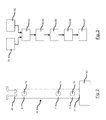
Figure 3 is flow diagram detailing the steps of the method according to an embodiment of the present invention ; -
Figure 4 is a graphic showing the dynamic mass flow rate qm2 calculated according to the method of the present invention, and by using a computerised simulation tool. - A detailed description of an exemplary embodiment of the invention follows with reference to the figures provided.
- The operation of a typical combustion engine intake system of a motor vehicle is well known.
- The intake manifold comprises a main intake duct referred to as a "plenum" and a plurality of runners or conduits that distribute airflow from the plenum to the intake ports of each cylinder of the engine. The intake port of each cylinder comprises at least one intake valve and a fuel injector allowing when the intake valve is opened an air/fuel mixture to be introduced into the corresponding combustion chamber of the engine.
- The intake valve shuts during the compression phase of the air/fuel mixture in the combustion chamber where it is combusted to drive pistons producing drive torque.
-
Figure 1 shows the main intake duct or plenum 11 of the intake manifold from which open out a series of intake runners which are each associated with one of the cylinders of the engine. For reasons of clarity, only oneconduit 12 and the intake valves of the cylinder heads are shown, in particular theintake valve 13 ofconduit 12. - The rapid motion (i.e. opening and closing) of the
intake valve 13 are the source of pressure and mass flow variations in theconduit 12 which is of constant diameter. - The engine performance (power and torque for instance), fuel consumption and emission levels are highly dependent on wave action created by the motion of the valves within the conduits.
- The method of the invention aims at measuring mass flow variations/dynamics in order to improve engine torque response, fuel consumption and overall volumetric efficiency.
- To do so, in summary, a relationship is established between the pressure and mass flow at two adequately distant points, this relationship being a frequency domain equation derived from a transfer matrix. Once the transfer matrix is known, mass flow may be derived.
- In accordance with the present invention, a
control device 50 is provided which is capable of determining mass airflow in theconduit 12. - The
control device 50 which is arranged to conduct the method of the invention includes acontrol unit 52 which preferably comprises a microprocessor, a read only memory (ROM) 51 storing various operating steps and a transfer matrix, and a random-access memory (RAM) 54 used by thecontrol unit 52 to store and retrieve data. - It is to be noted that the transfer matrix is determined in advance experimentally by means of tests using a dedicated or an appropriate test bench test bench, e.g. an engine test bench, or by means of simulation, and stored in the
ROM 51. - One possible method for determining the transfer matrix will be described below.
- In this embodiment, the
control device 50 regulates engine operations based on several inputs, in particular the pressure signals (or values) measured by thepressure sensors conduit 12. - The
pressure sensors intake valve 13 and are less than 100 mm apart, the internal diameter of theconduit 12 being 30 mm in this example. - The
control unit 52 is thus arranged to receive inputs (i.e. measured values of the pressure) from thepressure sensors port 53. - As will be discussed in further detail below, by employing the stored calculation steps, the stored transfer matrix, and the two pressure signals (inputs), the
control unit 52 is capable of determining air mass flow at any of the points A and B of theconduit 12. - A precise value of the mass flow in the
conduit 12 is consequently provided in real-time by thecontrol unit 52. - The value(s) of the determined mass flow can then be used as control signals for actuators of the internal combustion engine, or also for diagnosis purposes.
- In other words, the
control unit 52 processes the pressure signals according to the method of the invention, whose steps will be described below, in order to obtain mass flow signals which may be used to generate at least one command signal based thereon. - For instance, the
control device 50 may provide an output signal via the input/output port (I/O) 53 to control accurately the opening of the intake valves (intake valve timing), and thus improving volumetric efficency. Furthermore the knowledge of the instantaneous airflow allows to maintain a desired air-fuel ratio which is important to achieve optimal engine performance, fuel economy, and engine emissions. - In other words, taking into account the unsteady behavior of the pressure and mass flow, the opening of the intake valve may be timed to feed more air into the cylinder.
- In this embodiment, the
pressure sensors intake valve 13 to control the mass air flow entering the corresponding cylinder. - In other embodiments, the
pressure sensors - In relation to
Figure 3 , an explanation now follows describing the steps for determining the unsteady mass flow at points A and B of theconduit 12. - The real-time measurement device of the invention, called mass flow meter, comprises two
sensors conduit 12, thesensors - The mass flow meter comprises the
control device 50. Thecontrol unit 52 comprises signal processing means which process time domain information of the two pressure measurements by accessing their respective frequency spectrum (step 83), and means for calculating the instantaneous mass flow at points A and B (step 85) using linear equations relating the frequency spectrum of the mass flows to that of the measured pressures (step 84), the linear equations being derived from a calibration or transfer matrix obtained in advance (as mentioned previously). - Any of the mass flow signals may be processed (step 86) to generate at least one command signal (step 87) based thereon.
- We consider that pA, pB, qmA and qmB are respectively the pressure and mass flows in the time domain at points A and B, and that PA, PB, QmA and QmB are respectively the spectrum of pressures and mass flows in the frequency domain at points A and B.
- The one-dimensional plane wave theory with standing wave action flows allows to linearize the pressure and mass flow variables in the frequency domain and design transfer matrices having as coefficients U, V, W and X linking the information upstream (point A) to that downstream (point B).
- Such a transfer matrix is calculated and calibrated in advance for the pipe section between points A and B, in such a way to have :


- An appropriate signal processing allows retrieving time series data of mass flow in the time domain qmA.
- In other words, the two
pressure sensors conduit 12, and then the two measurements are used to calculate the mass flow at any of the measurement points A and B. - The dynamic mass flow rate, i.e. the fluctuating mass flow around a certain mean value is calculated using the pressure signals. Also, unlike the prior art teachings, it is not required to calculate the pressure difference between the points A and B.
- The pressure signals are transposed to the frequency domain (step 84) using a Fast Fourier Transform (FFT).
- The mass flow time domain values are obtained from the mass flow spectrum with an inverse Fast Fourier Transform (step 85)
- The device being designed to predict a mass flow for an engine and the signals being generally low frequency signals between 30 Hz and 200 Hz for fast running engines, the frequency range used is chosen between 0 and 1000 Hz.
- Unlike the known solutions that measure the mean value of the mass flow, the solution of the invention measures the dynamic part of the mass flow, i.e. concentrates on the dynamic part using linear equations as above.
- The solution of the invention is non-intrusive since the
pressure sensors conduit 12 and does not change the geometry (cross-section or length) of the conduit. - It is simple and fast to implement once the transfer matrix is known.
- It may be used for any engine configuration and engine speed.
- It is to be noted that the accurancy of the measurements depends on the sample frequency of the
pressure sensors - With respect to
Figure 2 , an explanation now follows describing the method used to obtain the transfer matrix coefficients U, V, W and X. - It comprises of an introduction to the different measurement techniques and how they are used to find the transfer matrix poles along with modeling theory explanation.
- The coefficients U, V, W and X are calculated for a given tube geometry and are obtained after pressure measurements on a dynamic flow bench. These coefficients are a mix of gas dynamics, linear acoustic plane wave theory, signal processing and calibration.
- Each coefficient is measured for a given tube geometry (95 mm of length and 30 mm of internal diameter for instance).
- i) When the gas dynamics equations are linearized, their solutions for pressure and mass flow take the form of harmonic variables. These can be written in transfer matrix form where the upstream pressure and mass flow are linked to the downstream variables via the transfer matrix expression. This is often done in the frequency domain because of the relative ease to transcript the harmonic solution into the frequency domain using a Fast Fourier Transform (FFT).
- There exists a number of experimental apparatuses that allow for transfer matrix measurement. This is normally done using acoustic linear theory.
- In the case of this invention, the inventors used the so-called "shock tube" technique, or the "dynamic flow bench".
- The "shock tube" technique is a technique where a tube is rigidly closed at one end and where an elastic membrane plugs the open end. The tube is connected to a vacuum pump. Once the desired level of vacuum is reached inside the tube, the elastic membrane is pierced and a shock wave propagates inside the tube. This causes important perturbations in pressure and mass flow. The pressure oscillations are recorded using pressure sensors.
- The inventors used another measurement technique implementing a device called a dynamic flow bench.
- The following paragraphs describe the measurement method on the dynamic flow bench and post- treatment procedures.
- ii) The dynamic flow bench is an experimental bench used by the inventors. It is a unique system that is used to measure pressure response inside a given part after a mass flow excitation.
- First, the part to be tested in mounted on the bench. This part can be any intake element, from simple pipes to elaborate intake systems (manifold, runners and pipes...). In the present case, it is a
simple tube 40 which is represented schematically on thedynamic flow bench 60 inFigure 2 . - The dynamic flow bench principle is to first create a steady mass flow inside the
tube 40. This is done using a Superflow (registered trademark) industrial pump, air being aspirated at the upperopen end 42 of thetube 40. - Once the flow is stabilized, i.e. the pressure drop is constant, the mass flow is extinguished abruptly. This is done in approximately 0.5 ms using a hydraulic actuator that closes a guillotine located at the
lower end 41 of thetube 40 and restricts the passage of the air. For example, the mass flow is extinguished from an initial value of 150 kg/h to zero in 0.5 ms. - The
bench 60 itself is equipped with a steady air mass sensor that enables the measurement of the initial desired mass flow, and the hydraulic guillotine is controlled via a computer interface. - In this example, the mounted part is a
simple tube 40 having an overall length of 252.5 mm and an internal diameter of 30 mm. Thistube 40 is equipped with threepressure sensors distinct locations tube 40 as shown inFigure 2 . - The distance between the
lower end 41 of thetube 40 and points 0, 1 and 2 is 45 mm, 112,5 mm and 207,5 mm respectively. - It is the specificity of the excitation nature on the bench, coupled with gas dynamics and acoustic linear theory that will allow, as it will be explained later on, to calculate a transfer matrix between pressure and mass flow at
points - This transfer matrix is then used on an engine to calculate the instantaneous mass flow using a pair of pressure sensors, according to the method described previously.
- An initial mass flow qme , called the excitation mass flow, is aspirated (as illustrated by the arrows) through the upper
open end 42 oftube 40 offigure 3 . Once this excitation mass flow is extinguished in 0.5 ms (once the guillotine is activated), it will create a pressure response inside thetube 40. The pressure wave that was created will reflect off the walls of the guillotine closing thelower end 41 and travel back to theopen end 42. At the openedend 42 of thepipe 40, it will reflect back into thetube 40 as so on and so forth until the wave action inside thetube 40 dies out. The oscillation of this air mass causes pressure and mass flow fluctuations inside thetube 40. The pressure fluctuations are directly measured using thepressure sensors - iii) We now describe the modeling based on gas dynamics theory, acoustics and signal processing.
- Following the mass flow excitation on the dynamic flow bench and the registration of the different pressure signals, the measurements are fed to a specially developed Matlab (registered trademark) routine that will calculate the transfer matrix between
points - a) The flow inside the piping of an internal combustion engine (and inside the pipe on the dynamic bench) is considered with the one-dimensional plane wave theory. Therefore, a second order differential equation can be written in terms of pressure at
point 0 of thetube 40 and different parameters with the excitation mass flow qme as a source term. These parameters are :- Frequency : equal to the frequency of oscillation of the pressure and mass flow fluctuations on the
dynamic flow bench 60 ; - Inertial parameter : sets the available energy for the waves after the guillotine closes ;
- Damping parameter : characterizes losses and friction effects that eventually lead the pressure and mass flow oscillations to die out.
- Frequency : equal to the frequency of oscillation of the pressure and mass flow fluctuations on the
- b) When the second order differential equation is transposed into the frequency domain using a Laplace transform, these parameters can be identified. Practically this is done by accessing the frequency domain of the measured pressure at
point 0 of thetube 40. This is done using a Fast Fourier Transform (FFT) algorithm with dedicated signal processing tools conceived for carrying out the task (filters, dynamic component only considered, proper windowing to eliminate high frequency noise...). - Once the parameters are known, a transfer function is established between the dynamic pressure oscillations at
point 0 and the excitation mass flow qme on the bench. - The transfer function is called PF0 :

- P0 is the pressure at
point 0 in the frequency domain : P0=FFT(p0(t)) where t is the time in seconds. - Qme is the excitation mass flow in the frequency domain :
- Qme = FFT(qme (t))
- The transfer function PF0 is used to find the matrix between
points - c) As stated before, after the guillotine closes the
lower end 41, the fluctuations inside thetube 40 start to take place on the dynamic flow bench. - However they take place according to a very specific harmonic resonance. Acoustic theory predicts that the pressure and mass flow inside the
tube 40 fluctuate according to the quarter wave length frequency of thetube 40. If the length of thetube 40 is L, then according to acoustic linear theory the frequencies of pressure and mass flow are given by : -

- The fluctuations take place with a multitude of resonant frequencies, each one being a multiple of (2i-1).
- This very specific resonance mode is known as quarter wave length resonance and is characteristic of a tube that is rigidly closed at one end and opened at the other, much like the
tube 40 on thedynamic bench 60 after excitation. - This resonance profile states that the pressure fluctuations have a maximum level at the closed end and a minimum level at the opened end and vice-versa for the mass flow fluctuations. Consequently, the theoretical pressure and mass flow distribution inside the
tube 40 on thebench 60 is known. - When this known pressure profile is combined with the pressure measurements at
points - PF1 is the transfer function linking dynamic pressure at
point 1 to the excitation mass flow :
- PF2 is the transfer function linking dynamic pressure at
point 2 to the excitation mass flow :
- QF1 is the transfer function linking dynamic mass flow at
point 1 to the excitation mass flow:
- QF2 is the transfer function linking dynamic mass flow at
point 2 to the excitation mass flow :
- d) The four transfer functions are now known. They link dynamic pressure and mass flow components in the frequency domain to the excitation mass flow on the
dynamic flow bench 60.
- d) The four transfer functions are now known. They link dynamic pressure and mass flow components in the frequency domain to the excitation mass flow on the
- This transfer function technique is often used in electronics and automatic studies to characterize any given system using its response to an impulse excitation. The system in this case consists of an air mass trapped inside the tube.
- The transfer functions are important to be characterized because they represent a model that will be now used to obtain the transfer matrix.
- e) Albeit the impulse excitation on the
dynamic flow bench 60 enables an excellent characterization of thetube 40, it cannot be reproduced a multitude of times. It resembles one very rapid closing of the intake valve on an engine. - However, in an engine, the intake valves open and close many times and create a standing wave action inside the intake system.
- As stated before, the pressure response on the
dynamic bench 60 lasts only 0.25 sec, whereas on an actual engine it lasts as long as the engine is running. - Using the four transfer functions and Simulink (registered trademark), an artificial excitation that is long lasting and that covers a broad frequency range is artificially created and used as an input excitation to the four transfer functions.
- These transfer functions will then output computed values for pressure and mass flow.
- Let P1s, P2s, Qm1s and Qm2s be the respective output values of the four transfer functions after excitation in the Simulink routine.
- f) Now the transfer matrix can be calculated. The transfer matrix theory states that pressure and mass flow for a given geometry are linked together in the frequency domain. The transfer matrix is written as :

- The simple tube is considered to be symmetrical and reversible.
- Therefore, the transfer matrix terms verify the following conditions :
- AD-BC=-1 and A=D
- Solving the systems of four equations, the four unknown terms A, B, C and D can be calculated. Practically, they represent a frequency domain vector.
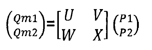
- The transfer matrix can also be written in a way to give mass flow as a function of pressure. By re-arranging terms, one could write :
- iv) We now describe the use of the transfer matrix to measure instantaneous mass flow in an engine.
- The transfer matrix gives the mass flow dynamic component as a function of pressure at
points - In the example of
Figure 2 , the geometry between these twopoints - Theory states that the transfer matrix is independent of the upstream and downstream conditions and that it is linear in nature.
- This means that the identified transfer matrix on the
dynamic flow bench 60 can be used to measure information on an actual engine. - A tube with a 30 mm cross section diameter with two pressure sensors distant 95mm from each other can be installed anywhere on the engine intake and the pressure information can be used to measure instantaneous dynamic mass flow.
- For example, the mass flow in the frequency domain at
point 1 is given by
- The mass flow traces or actual time domain values are obtained with an inverse Fast Fourier Transform :

- In summary, the proposed device for mass flow measurements requires no tuning or calibration.
- Once the transfer matrix is known, it can be used anywhere in the intake line on any engine configuration.
- The device employs a transfer matrix technique in the frequency domain and bridges the gap between the limitation of the frequency domain acoustic theory and the time domain analysis.
- The device links pressure and mass flow directly and implicitly takes into account air density fluctuations and temperature effects.
- Such a solution was validated by simulation as shown in
Figure 4 . - The dotted line represents the dynamic mass flow rate qm2 calculated according to the method of the present invention, the continous line representing the dynamic mass flow rate qm2 obtained by using the GT-Power (registered Trademark) simulation tool.
- It appears clearly that the values of the dynamic mass flow rate qm2 calculated according to the method of the present invention are accurate and that such a method is reliable.
- The above embodiments are to be understood as illustrative examples of the invention.
- Further embodiments of the invention are envisaged.
- It is to be understood that any feature described in relation to one embodiment may also be used in other of the embodiments. Furthermore, equivalents and modifications not described above may also be employed without departing from the scope of the invention, which is defined in the accompanying claims.
- Throughout the description and claims of this specification, the words "comprise" and "contain" and variations of them mean "including but not limited to", and they are not intended to (and do not) exclude other components.
Claims (11)
- A method for determining the instantaneous mass flow of a gas, such as air in a conduit (12), like an air intake channel of an internal combustion engine of a motor vehicle, said method comprising the steps of:- measuring (81) a time-domain signal of gas pressure at a first measurement point (A) of said conduit (12);- measuring (82) a time-domain signal of gas pressure at a second measurement point (B) of said conduit (12),
characterised in that said method further comprises the steps of:- obtaining (83) for each of the measured time-domain signals of gas pressure the corresponding frequency spectrum;- obtaining (84) the frequency spectrum of the mass flow at each of said measurement points (A, B) using a model in the frequency domain linking the frequency spectrum of the measured gas pressure at said measurement points (A, B) to the frequency spectrum of the mass flow at said measurement points (A, B);- obtaining (85) the time-domain signal of the mass flow rate at any measurement point (A, B) from the frequency spectrum of the mass flow at said corresponding measurement point (A, B). - A method according to claim 1, characterised in that said model is a transfer matrix.
- A method according to claim 1 or 2, characterised in that the step of obtaining (84) the frequency spectrum of the mass flow at each of said measurement points (A, B) consists in solving a frequency-domain linear equation determined from said model.
- A method according to claim 2 or 3, characterised in that said transfer matrix is derived experimentally by measuring pressure response inside a given conduit after a mass flow excitation.
- A method according to any one of claims 1 to 4, characterised in that it further comprises the steps of developing (86) an engine control command as a function of the computed time-domain signal of the mass flow rate at any measurement point (A, B) and controlling (87) engine operation in accordance with the developed control command (86).
- A method according to any one of claims 1 to 5, characterised in that the frequency spectrum of each of the measured pressure signals is obtained using a Fast Fourier Transform.
- A method according to any one of claims 1 to 6, characterised in that the time-domain signal of the mass flow rate at any measurement point (A, B) is obtained using an inverse Fast Fourier Transform.
- Device for determining the instantaneous mass flow of a gas, such as air in a conduit (12), like an air intake channel of an internal combustion engine of a motor vehicle, said device comprising:- means for measuring (21) a time-domain signal of gas pressure at a first measurement point (A) of said conduit (12);- means for measuring (22) a time-domain signal of gas pressure at a second measurement point (B) of said conduit (12),
said device being characterised in that it further comprises:- means for obtaining (50) for each of the measured time-domain signals of gas pressure the corresponding frequency spectrum;- means for obtaining (50) the frequency spectrum of the mass flow at each of said measurement points (A, B) using a model in the frequency domain linking the frequency spectrum of the measured gas pressure at said measurement points (A, B) to the frequency spectrum of the mass flow at said measurement points (A, B);- means for obtaining (50) the time-domain signal of the mass flow rate at any measurement point (A, B) from the frequency spectrum of the mass flow at said corresponding measurement point (A, B). - Device according to claim 8, characterised in that comprises means (50) for developing (50) an engine control command as a function of the computed time-domain signal of the mass flow rate at any measurement point (A, B) and means for controlling engine operation in accordance with the developed control command.
- Device according to claim 8 or 9, characterised in that the means for measuring (21, 22) the time-domain signals of the gas pressure at said measurement points comprises two pressure sensors (21, 22) flush-mounted within the conduit (12).
- A computer program recorded on a computer-readable medium and capable of being run by a processor, characterised in that the program includes program code instructions for implementing the method according to any one of claims 1 to 7.
Priority Applications (1)
| Application Number | Priority Date | Filing Date | Title |
|---|---|---|---|
| EP14290092.7A EP2927465B1 (en) | 2014-04-02 | 2014-04-02 | Method for determining the instantaneous mass flow rate of a gas, corresponding device and computer program |
Applications Claiming Priority (1)
| Application Number | Priority Date | Filing Date | Title |
|---|---|---|---|
| EP14290092.7A EP2927465B1 (en) | 2014-04-02 | 2014-04-02 | Method for determining the instantaneous mass flow rate of a gas, corresponding device and computer program |
Publications (2)
| Publication Number | Publication Date |
|---|---|
| EP2927465A1 true EP2927465A1 (en) | 2015-10-07 |
| EP2927465B1 EP2927465B1 (en) | 2021-03-10 |
Family
ID=50630720
Family Applications (1)
| Application Number | Title | Priority Date | Filing Date |
|---|---|---|---|
| EP14290092.7A Active EP2927465B1 (en) | 2014-04-02 | 2014-04-02 | Method for determining the instantaneous mass flow rate of a gas, corresponding device and computer program |
Country Status (1)
| Country | Link |
|---|---|
| EP (1) | EP2927465B1 (en) |
Cited By (4)
| Publication number | Priority date | Publication date | Assignee | Title |
|---|---|---|---|---|
| CN109359418A (en) * | 2018-11-09 | 2019-02-19 | 深圳大学 | Prediction method, system and storage medium for nonlinear wind-induced response of a suspension bridge |
| CN109653890A (en) * | 2017-10-11 | 2019-04-19 | 罗伯特·博世有限公司 | Method for obtaining the air quality flow of internal combustion engine |
| CN113283044A (en) * | 2021-06-21 | 2021-08-20 | 上海天麦能源科技有限公司 | Edge calculation method for urban gas pipe network blockage diagnosis |
| US11365699B2 (en) * | 2018-09-26 | 2022-06-21 | Hitachi Astemo, Ltd. | Internal combustion engine control device |
Citations (6)
| Publication number | Priority date | Publication date | Assignee | Title |
|---|---|---|---|---|
| DE10125166A1 (en) * | 2001-05-23 | 2002-12-05 | Volkswagen Ag | Diagnosing combustion engine external exhaust gas feedback system involves estimating exhaust gas feedback line free transmission cross-section using known engine operating parameters |
| DE102004010903B3 (en) * | 2004-03-05 | 2005-09-08 | Siemens Ag | Measurement and supply of air to cylinder of internal combustion engine involves noise sensor on outside of cylinder connected to computer controlling opening of throttle valve |
| DE102005007057A1 (en) * | 2005-02-15 | 2006-08-24 | Fev Motorentechnik Gmbh | Fluid flow control method for e.g. motor vehicle`s internal combustion engine, involves determining average value of characteristics values for dynamic behavior of fluid flow parameter changing with varying load conditions, over time period |
| WO2009118290A1 (en) | 2008-03-28 | 2009-10-01 | Centre National De La Recherche Scientifique (Cnrs) | Real-time non-stationary flowmeter |
| DE102009027010A1 (en) * | 2009-06-18 | 2010-12-23 | Robert Bosch Gmbh | Method for diagnosing an actuator of a boost pressure system of an internal combustion engine |
| US20120101745A1 (en) * | 2010-10-26 | 2012-04-26 | Denso Corporation | Flow measuring device |
Family Cites Families (2)
| Publication number | Priority date | Publication date | Assignee | Title |
|---|---|---|---|---|
| US7881885B2 (en) * | 2005-06-17 | 2011-02-01 | Buelent Uensal | Method and device for determining the instantaneous mass flow of pulsating flows |
| US20140200836A1 (en) * | 2011-06-30 | 2014-07-17 | Pedro Jose Lee | Flow rate determination method and apparatus |
-
2014
- 2014-04-02 EP EP14290092.7A patent/EP2927465B1/en active Active
Patent Citations (6)
| Publication number | Priority date | Publication date | Assignee | Title |
|---|---|---|---|---|
| DE10125166A1 (en) * | 2001-05-23 | 2002-12-05 | Volkswagen Ag | Diagnosing combustion engine external exhaust gas feedback system involves estimating exhaust gas feedback line free transmission cross-section using known engine operating parameters |
| DE102004010903B3 (en) * | 2004-03-05 | 2005-09-08 | Siemens Ag | Measurement and supply of air to cylinder of internal combustion engine involves noise sensor on outside of cylinder connected to computer controlling opening of throttle valve |
| DE102005007057A1 (en) * | 2005-02-15 | 2006-08-24 | Fev Motorentechnik Gmbh | Fluid flow control method for e.g. motor vehicle`s internal combustion engine, involves determining average value of characteristics values for dynamic behavior of fluid flow parameter changing with varying load conditions, over time period |
| WO2009118290A1 (en) | 2008-03-28 | 2009-10-01 | Centre National De La Recherche Scientifique (Cnrs) | Real-time non-stationary flowmeter |
| DE102009027010A1 (en) * | 2009-06-18 | 2010-12-23 | Robert Bosch Gmbh | Method for diagnosing an actuator of a boost pressure system of an internal combustion engine |
| US20120101745A1 (en) * | 2010-10-26 | 2012-04-26 | Denso Corporation | Flow measuring device |
Cited By (5)
| Publication number | Priority date | Publication date | Assignee | Title |
|---|---|---|---|---|
| CN109653890A (en) * | 2017-10-11 | 2019-04-19 | 罗伯特·博世有限公司 | Method for obtaining the air quality flow of internal combustion engine |
| US11365699B2 (en) * | 2018-09-26 | 2022-06-21 | Hitachi Astemo, Ltd. | Internal combustion engine control device |
| CN109359418A (en) * | 2018-11-09 | 2019-02-19 | 深圳大学 | Prediction method, system and storage medium for nonlinear wind-induced response of a suspension bridge |
| CN113283044A (en) * | 2021-06-21 | 2021-08-20 | 上海天麦能源科技有限公司 | Edge calculation method for urban gas pipe network blockage diagnosis |
| CN113283044B (en) * | 2021-06-21 | 2023-11-21 | 上海天麦能源科技有限公司 | An edge computing method for blockage diagnosis of urban gas pipeline network |
Also Published As
| Publication number | Publication date |
|---|---|
| EP2927465B1 (en) | 2021-03-10 |
Similar Documents
| Publication | Publication Date | Title |
|---|---|---|
| US20180128660A1 (en) | Flow rate determination method and apparatus | |
| CN110296327B (en) | A Pipeline Leak Detection Method Based on Transient Flow Frequency Response Analysis | |
| CN101230807B (en) | Air filter throttle monitoring without pressure sensor before choker | |
| EP2927465B1 (en) | Method for determining the instantaneous mass flow rate of a gas, corresponding device and computer program | |
| Piscaglia et al. | Development of a non-reflecting boundary condition for multidimensional nonlinear duct acoustic computation | |
| Mezher et al. | Frequency based approach for simulating pressure waves at the inlet of internal combustion engines using a parameterized model | |
| Brahma | Measurement and prediction of discharge coefficients in highly compressible pulsating flows to improve EGR flow estimation and modeling of engine flows | |
| Młynarczyk et al. | The application of nozzles for the attenuation of volumetric compressor pressure pulsation | |
| Ferrari et al. | Modal analysis of fuel injection systems and the determination of a transfer function between rail pressure and injection rate | |
| Liu et al. | A modified time domain approach for calculation of noise reduction and acoustic impedance of intake duct system | |
| Costall et al. | Fundamental characterization of turbocharger turbine unsteady flow behavior | |
| Chalet et al. | Analysis of unsteady flow through a throttle valve using CFD | |
| EP3368760B1 (en) | Systems and methods for detecting anomalies at pressure sensors | |
| EP3368758B1 (en) | Systems and methods for in-cylinder pressure estimation using pressure wave modeling | |
| Liu et al. | A hybrid time-frequency domain method to predict insertion loss of intake system | |
| Młynarczyk et al. | The estimation of the pressure pulsation damping coefficient of a nozzle | |
| Peerlings | Methods and techniques for precise and accurate in-duct aero-acoustic measurements: Application to the area expansion | |
| Mohamad | A review of flow acoustic effects on a commercial automotive exhaust system-methods and materials | |
| Moser et al. | Using exhaust pressure pulsations to detect deteriorations of oxygen sensor dynamics | |
| Torregrosa et al. | Assessment of acoustic reciprocity and conservativeness in exhaust aftertreatment systems | |
| Zheng et al. | An experimentally validated multifidelity hybrid model for analyzing the pressure variation of a relief system | |
| Ferrari et al. | Modal analysis as a design tool for dynamical optimization of Common Rail fuel injection systems | |
| Stiaccini et al. | Analysis of valve-retainer orientation influence on a reciprocating compressor for natural gas vehicle refueling stations | |
| CN112798281A (en) | Device and method for simulating complete machine air inlet waveform by single cylinder | |
| CN118643692B (en) | A method for acoustic mode identification during solid rocket engine testing |
Legal Events
| Date | Code | Title | Description |
|---|---|---|---|
| PUAI | Public reference made under article 153(3) epc to a published international application that has entered the european phase |
Free format text: ORIGINAL CODE: 0009012 |
|
| AK | Designated contracting states |
Kind code of ref document: A1 Designated state(s): AL AT BE BG CH CY CZ DE DK EE ES FI FR GB GR HR HU IE IS IT LI LT LU LV MC MK MT NL NO PL PT RO RS SE SI SK SM TR |
|
| AX | Request for extension of the european patent |
Extension state: BA ME |
|
| 17P | Request for examination filed |
Effective date: 20160304 |
|
| RBV | Designated contracting states (corrected) |
Designated state(s): AL AT BE BG CH CY CZ DE DK EE ES FI FR GB GR HR HU IE IS IT LI LT LU LV MC MK MT NL NO PL PT RO RS SE SI SK SM TR |
|
| STAA | Information on the status of an ep patent application or granted ep patent |
Free format text: STATUS: EXAMINATION IS IN PROGRESS |
|
| 17Q | First examination report despatched |
Effective date: 20190516 |
|
| RAP1 | Party data changed (applicant data changed or rights of an application transferred) |
Owner name: MANN+HUMMEL GMBH |
|
| RIC1 | Information provided on ipc code assigned before grant |
Ipc: F02D 41/00 20060101AFI20200326BHEP Ipc: F02D 41/28 20060101ALN20200326BHEP Ipc: F02D 41/18 20060101ALN20200326BHEP |
|
| RIC1 | Information provided on ipc code assigned before grant |
Ipc: F02D 41/00 20060101AFI20200327BHEP Ipc: F02D 41/28 20060101ALN20200327BHEP Ipc: F02D 41/18 20060101ALN20200327BHEP |
|
| RIC1 | Information provided on ipc code assigned before grant |
Ipc: F02D 41/18 20060101ALN20200421BHEP Ipc: F02D 41/00 20060101AFI20200421BHEP Ipc: F02D 41/28 20060101ALN20200421BHEP |
|
| RIC1 | Information provided on ipc code assigned before grant |
Ipc: F02D 41/28 20060101ALN20200518BHEP Ipc: F02D 41/00 20060101AFI20200518BHEP Ipc: F02D 41/18 20060101ALN20200518BHEP |
|
| RIC1 | Information provided on ipc code assigned before grant |
Ipc: F02D 41/00 20060101AFI20200724BHEP Ipc: F02D 41/28 20060101ALN20200724BHEP Ipc: F02D 41/18 20060101ALN20200724BHEP |
|
| REG | Reference to a national code |
Ref country code: DE Ref legal event code: R079 Ref document number: 602014075521 Country of ref document: DE Free format text: PREVIOUS MAIN CLASS: F02D0041000000 Ipc: F02D0041180000 |
|
| RIC1 | Information provided on ipc code assigned before grant |
Ipc: F02D 41/28 20060101ALN20200901BHEP Ipc: G01F 1/76 20060101ALI20200901BHEP Ipc: G01F 1/72 20060101ALI20200901BHEP Ipc: G01F 1/34 20060101ALI20200901BHEP Ipc: F02D 41/18 20060101AFI20200901BHEP Ipc: G01F 1/66 20060101ALI20200901BHEP |
|
| GRAP | Despatch of communication of intention to grant a patent |
Free format text: ORIGINAL CODE: EPIDOSNIGR1 |
|
| STAA | Information on the status of an ep patent application or granted ep patent |
Free format text: STATUS: GRANT OF PATENT IS INTENDED |
|
| RIC1 | Information provided on ipc code assigned before grant |
Ipc: G01F 1/34 20060101ALI20200911BHEP Ipc: F02D 41/28 20060101ALN20200911BHEP Ipc: F02D 41/18 20060101AFI20200911BHEP Ipc: G01F 1/76 20060101ALI20200911BHEP Ipc: G01F 1/66 20060101ALI20200911BHEP Ipc: G01F 1/72 20060101ALI20200911BHEP |
|
| INTG | Intention to grant announced |
Effective date: 20201021 |
|
| GRAS | Grant fee paid |
Free format text: ORIGINAL CODE: EPIDOSNIGR3 |
|
| GRAA | (expected) grant |
Free format text: ORIGINAL CODE: 0009210 |
|
| STAA | Information on the status of an ep patent application or granted ep patent |
Free format text: STATUS: THE PATENT HAS BEEN GRANTED |
|
| RIN1 | Information on inventor provided before grant (corrected) |
Inventor name: MEZHER, HAITHAM Inventor name: CHESSE, PASCAL Inventor name: MIGAUD, JEROME Inventor name: RAIMBAULT, VINCENT Inventor name: CHALET, DAVID |
|
| AK | Designated contracting states |
Kind code of ref document: B1 Designated state(s): AL AT BE BG CH CY CZ DE DK EE ES FI FR GB GR HR HU IE IS IT LI LT LU LV MC MK MT NL NO PL PT RO RS SE SI SK SM TR |
|
| REG | Reference to a national code |
Ref country code: GB Ref legal event code: FG4D |
|
| REG | Reference to a national code |
Ref country code: AT Ref legal event code: REF Ref document number: 1370051 Country of ref document: AT Kind code of ref document: T Effective date: 20210315 Ref country code: CH Ref legal event code: EP |
|
| REG | Reference to a national code |
Ref country code: IE Ref legal event code: FG4D |
|
| REG | Reference to a national code |
Ref country code: DE Ref legal event code: R096 Ref document number: 602014075521 Country of ref document: DE |
|
| RAP4 | Party data changed (patent owner data changed or rights of a patent transferred) |
Owner name: MANN+HUMMEL GMBH |
|
| REG | Reference to a national code |
Ref country code: LT Ref legal event code: MG9D |
|
| PG25 | Lapsed in a contracting state [announced via postgrant information from national office to epo] |
Ref country code: LT Free format text: LAPSE BECAUSE OF FAILURE TO SUBMIT A TRANSLATION OF THE DESCRIPTION OR TO PAY THE FEE WITHIN THE PRESCRIBED TIME-LIMIT Effective date: 20210310 Ref country code: HR Free format text: LAPSE BECAUSE OF FAILURE TO SUBMIT A TRANSLATION OF THE DESCRIPTION OR TO PAY THE FEE WITHIN THE PRESCRIBED TIME-LIMIT Effective date: 20210310 Ref country code: GR Free format text: LAPSE BECAUSE OF FAILURE TO SUBMIT A TRANSLATION OF THE DESCRIPTION OR TO PAY THE FEE WITHIN THE PRESCRIBED TIME-LIMIT Effective date: 20210611 Ref country code: FI Free format text: LAPSE BECAUSE OF FAILURE TO SUBMIT A TRANSLATION OF THE DESCRIPTION OR TO PAY THE FEE WITHIN THE PRESCRIBED TIME-LIMIT Effective date: 20210310 Ref country code: BG Free format text: LAPSE BECAUSE OF FAILURE TO SUBMIT A TRANSLATION OF THE DESCRIPTION OR TO PAY THE FEE WITHIN THE PRESCRIBED TIME-LIMIT Effective date: 20210610 Ref country code: NO Free format text: LAPSE BECAUSE OF FAILURE TO SUBMIT A TRANSLATION OF THE DESCRIPTION OR TO PAY THE FEE WITHIN THE PRESCRIBED TIME-LIMIT Effective date: 20210610 |
|
| REG | Reference to a national code |
Ref country code: AT Ref legal event code: MK05 Ref document number: 1370051 Country of ref document: AT Kind code of ref document: T Effective date: 20210310 |
|
| REG | Reference to a national code |
Ref country code: NL Ref legal event code: MP Effective date: 20210310 |
|
| PG25 | Lapsed in a contracting state [announced via postgrant information from national office to epo] |
Ref country code: SE Free format text: LAPSE BECAUSE OF FAILURE TO SUBMIT A TRANSLATION OF THE DESCRIPTION OR TO PAY THE FEE WITHIN THE PRESCRIBED TIME-LIMIT Effective date: 20210310 Ref country code: RS Free format text: LAPSE BECAUSE OF FAILURE TO SUBMIT A TRANSLATION OF THE DESCRIPTION OR TO PAY THE FEE WITHIN THE PRESCRIBED TIME-LIMIT Effective date: 20210310 Ref country code: LV Free format text: LAPSE BECAUSE OF FAILURE TO SUBMIT A TRANSLATION OF THE DESCRIPTION OR TO PAY THE FEE WITHIN THE PRESCRIBED TIME-LIMIT Effective date: 20210310 |
|
| PG25 | Lapsed in a contracting state [announced via postgrant information from national office to epo] |
Ref country code: NL Free format text: LAPSE BECAUSE OF FAILURE TO SUBMIT A TRANSLATION OF THE DESCRIPTION OR TO PAY THE FEE WITHIN THE PRESCRIBED TIME-LIMIT Effective date: 20210310 |
|
| PG25 | Lapsed in a contracting state [announced via postgrant information from national office to epo] |
Ref country code: SM Free format text: LAPSE BECAUSE OF FAILURE TO SUBMIT A TRANSLATION OF THE DESCRIPTION OR TO PAY THE FEE WITHIN THE PRESCRIBED TIME-LIMIT Effective date: 20210310 Ref country code: AT Free format text: LAPSE BECAUSE OF FAILURE TO SUBMIT A TRANSLATION OF THE DESCRIPTION OR TO PAY THE FEE WITHIN THE PRESCRIBED TIME-LIMIT Effective date: 20210310 Ref country code: CZ Free format text: LAPSE BECAUSE OF FAILURE TO SUBMIT A TRANSLATION OF THE DESCRIPTION OR TO PAY THE FEE WITHIN THE PRESCRIBED TIME-LIMIT Effective date: 20210310 Ref country code: EE Free format text: LAPSE BECAUSE OF FAILURE TO SUBMIT A TRANSLATION OF THE DESCRIPTION OR TO PAY THE FEE WITHIN THE PRESCRIBED TIME-LIMIT Effective date: 20210310 |
|
| PG25 | Lapsed in a contracting state [announced via postgrant information from national office to epo] |
Ref country code: ES Free format text: LAPSE BECAUSE OF FAILURE TO SUBMIT A TRANSLATION OF THE DESCRIPTION OR TO PAY THE FEE WITHIN THE PRESCRIBED TIME-LIMIT Effective date: 20210310 Ref country code: PT Free format text: LAPSE BECAUSE OF FAILURE TO SUBMIT A TRANSLATION OF THE DESCRIPTION OR TO PAY THE FEE WITHIN THE PRESCRIBED TIME-LIMIT Effective date: 20210712 Ref country code: PL Free format text: LAPSE BECAUSE OF FAILURE TO SUBMIT A TRANSLATION OF THE DESCRIPTION OR TO PAY THE FEE WITHIN THE PRESCRIBED TIME-LIMIT Effective date: 20210310 Ref country code: SK Free format text: LAPSE BECAUSE OF FAILURE TO SUBMIT A TRANSLATION OF THE DESCRIPTION OR TO PAY THE FEE WITHIN THE PRESCRIBED TIME-LIMIT Effective date: 20210310 Ref country code: RO Free format text: LAPSE BECAUSE OF FAILURE TO SUBMIT A TRANSLATION OF THE DESCRIPTION OR TO PAY THE FEE WITHIN THE PRESCRIBED TIME-LIMIT Effective date: 20210310 Ref country code: IS Free format text: LAPSE BECAUSE OF FAILURE TO SUBMIT A TRANSLATION OF THE DESCRIPTION OR TO PAY THE FEE WITHIN THE PRESCRIBED TIME-LIMIT Effective date: 20210710 |
|
| REG | Reference to a national code |
Ref country code: DE Ref legal event code: R097 Ref document number: 602014075521 Country of ref document: DE |
|
| PG25 | Lapsed in a contracting state [announced via postgrant information from national office to epo] |
Ref country code: LU Free format text: LAPSE BECAUSE OF NON-PAYMENT OF DUE FEES Effective date: 20210402 |
|
| PLBE | No opposition filed within time limit |
Free format text: ORIGINAL CODE: 0009261 |
|
| STAA | Information on the status of an ep patent application or granted ep patent |
Free format text: STATUS: NO OPPOSITION FILED WITHIN TIME LIMIT |
|
| REG | Reference to a national code |
Ref country code: BE Ref legal event code: MM Effective date: 20210430 |
|
| PG25 | Lapsed in a contracting state [announced via postgrant information from national office to epo] |
Ref country code: DK Free format text: LAPSE BECAUSE OF FAILURE TO SUBMIT A TRANSLATION OF THE DESCRIPTION OR TO PAY THE FEE WITHIN THE PRESCRIBED TIME-LIMIT Effective date: 20210310 Ref country code: MC Free format text: LAPSE BECAUSE OF FAILURE TO SUBMIT A TRANSLATION OF THE DESCRIPTION OR TO PAY THE FEE WITHIN THE PRESCRIBED TIME-LIMIT Effective date: 20210310 Ref country code: LI Free format text: LAPSE BECAUSE OF NON-PAYMENT OF DUE FEES Effective date: 20210430 Ref country code: CH Free format text: LAPSE BECAUSE OF NON-PAYMENT OF DUE FEES Effective date: 20210430 Ref country code: AL Free format text: LAPSE BECAUSE OF FAILURE TO SUBMIT A TRANSLATION OF THE DESCRIPTION OR TO PAY THE FEE WITHIN THE PRESCRIBED TIME-LIMIT Effective date: 20210310 |
|
| 26N | No opposition filed |
Effective date: 20211213 |
|
| GBPC | Gb: european patent ceased through non-payment of renewal fee |
Effective date: 20210610 |
|
| PG25 | Lapsed in a contracting state [announced via postgrant information from national office to epo] |
Ref country code: SI Free format text: LAPSE BECAUSE OF FAILURE TO SUBMIT A TRANSLATION OF THE DESCRIPTION OR TO PAY THE FEE WITHIN THE PRESCRIBED TIME-LIMIT Effective date: 20210310 |
|
| PG25 | Lapsed in a contracting state [announced via postgrant information from national office to epo] |
Ref country code: IT Free format text: LAPSE BECAUSE OF FAILURE TO SUBMIT A TRANSLATION OF THE DESCRIPTION OR TO PAY THE FEE WITHIN THE PRESCRIBED TIME-LIMIT Effective date: 20210310 Ref country code: IE Free format text: LAPSE BECAUSE OF NON-PAYMENT OF DUE FEES Effective date: 20210402 Ref country code: GB Free format text: LAPSE BECAUSE OF NON-PAYMENT OF DUE FEES Effective date: 20210610 |
|
| PG25 | Lapsed in a contracting state [announced via postgrant information from national office to epo] |
Ref country code: IS Free format text: LAPSE BECAUSE OF FAILURE TO SUBMIT A TRANSLATION OF THE DESCRIPTION OR TO PAY THE FEE WITHIN THE PRESCRIBED TIME-LIMIT Effective date: 20210710 |
|
| PG25 | Lapsed in a contracting state [announced via postgrant information from national office to epo] |
Ref country code: BE Free format text: LAPSE BECAUSE OF NON-PAYMENT OF DUE FEES Effective date: 20210430 |
|
| PG25 | Lapsed in a contracting state [announced via postgrant information from national office to epo] |
Ref country code: HU Free format text: LAPSE BECAUSE OF FAILURE TO SUBMIT A TRANSLATION OF THE DESCRIPTION OR TO PAY THE FEE WITHIN THE PRESCRIBED TIME-LIMIT; INVALID AB INITIO Effective date: 20140402 |
|
| PG25 | Lapsed in a contracting state [announced via postgrant information from national office to epo] |
Ref country code: CY Free format text: LAPSE BECAUSE OF FAILURE TO SUBMIT A TRANSLATION OF THE DESCRIPTION OR TO PAY THE FEE WITHIN THE PRESCRIBED TIME-LIMIT Effective date: 20210310 |
|
| PG25 | Lapsed in a contracting state [announced via postgrant information from national office to epo] |
Ref country code: MK Free format text: LAPSE BECAUSE OF FAILURE TO SUBMIT A TRANSLATION OF THE DESCRIPTION OR TO PAY THE FEE WITHIN THE PRESCRIBED TIME-LIMIT Effective date: 20210310 |
|
| PG25 | Lapsed in a contracting state [announced via postgrant information from national office to epo] |
Ref country code: MT Free format text: LAPSE BECAUSE OF FAILURE TO SUBMIT A TRANSLATION OF THE DESCRIPTION OR TO PAY THE FEE WITHIN THE PRESCRIBED TIME-LIMIT Effective date: 20210310 |
|
| PG25 | Lapsed in a contracting state [announced via postgrant information from national office to epo] |
Ref country code: TR Free format text: LAPSE BECAUSE OF FAILURE TO SUBMIT A TRANSLATION OF THE DESCRIPTION OR TO PAY THE FEE WITHIN THE PRESCRIBED TIME-LIMIT Effective date: 20210310 |
|
| PGFP | Annual fee paid to national office [announced via postgrant information from national office to epo] |
Ref country code: DE Payment date: 20260422 Year of fee payment: 13 |
|
| PGFP | Annual fee paid to national office [announced via postgrant information from national office to epo] |
Ref country code: FR Payment date: 20260420 Year of fee payment: 13 |