EP2927430A1 - Stator vane with a cooled platform for a gas turbine engine - Google Patents
Stator vane with a cooled platform for a gas turbine engine Download PDFInfo
- Publication number
- EP2927430A1 EP2927430A1 EP15162139.8A EP15162139A EP2927430A1 EP 2927430 A1 EP2927430 A1 EP 2927430A1 EP 15162139 A EP15162139 A EP 15162139A EP 2927430 A1 EP2927430 A1 EP 2927430A1
- Authority
- EP
- European Patent Office
- Prior art keywords
- stator vane
- platform
- impingement plate
- turbine
- vane according
- Prior art date
- Legal status (The legal status is an assumption and is not a legal conclusion. Google has not performed a legal analysis and makes no representation as to the accuracy of the status listed.)
- Granted
Links
Images


Classifications
-
- F—MECHANICAL ENGINEERING; LIGHTING; HEATING; WEAPONS; BLASTING
- F01—MACHINES OR ENGINES IN GENERAL; ENGINE PLANTS IN GENERAL; STEAM ENGINES
- F01D—NON-POSITIVE DISPLACEMENT MACHINES OR ENGINES, e.g. STEAM TURBINES
- F01D9/00—Stators
- F01D9/02—Nozzles; Nozzle boxes; Stator blades; Guide conduits, e.g. individual nozzles
-
- F—MECHANICAL ENGINEERING; LIGHTING; HEATING; WEAPONS; BLASTING
- F01—MACHINES OR ENGINES IN GENERAL; ENGINE PLANTS IN GENERAL; STEAM ENGINES
- F01D—NON-POSITIVE DISPLACEMENT MACHINES OR ENGINES, e.g. STEAM TURBINES
- F01D1/00—Non-positive-displacement machines or engines, e.g. steam turbines
- F01D1/02—Non-positive-displacement machines or engines, e.g. steam turbines with stationary working-fluid guiding means and bladed or like rotor, e.g. multi-bladed impulse steam turbines
-
- F—MECHANICAL ENGINEERING; LIGHTING; HEATING; WEAPONS; BLASTING
- F01—MACHINES OR ENGINES IN GENERAL; ENGINE PLANTS IN GENERAL; STEAM ENGINES
- F01D—NON-POSITIVE DISPLACEMENT MACHINES OR ENGINES, e.g. STEAM TURBINES
- F01D25/00—Component parts, details, or accessories, not provided for in, or of interest apart from, other groups
- F01D25/08—Cooling; Heating; Heat-insulation
- F01D25/12—Cooling
-
- F—MECHANICAL ENGINEERING; LIGHTING; HEATING; WEAPONS; BLASTING
- F01—MACHINES OR ENGINES IN GENERAL; ENGINE PLANTS IN GENERAL; STEAM ENGINES
- F01D—NON-POSITIVE DISPLACEMENT MACHINES OR ENGINES, e.g. STEAM TURBINES
- F01D5/00—Blades; Blade-carrying members; Heating, heat-insulating, cooling or antivibration means on the blades or the members
- F01D5/02—Blade-carrying members, e.g. rotors
-
- F—MECHANICAL ENGINEERING; LIGHTING; HEATING; WEAPONS; BLASTING
- F01—MACHINES OR ENGINES IN GENERAL; ENGINE PLANTS IN GENERAL; STEAM ENGINES
- F01D—NON-POSITIVE DISPLACEMENT MACHINES OR ENGINES, e.g. STEAM TURBINES
- F01D5/00—Blades; Blade-carrying members; Heating, heat-insulating, cooling or antivibration means on the blades or the members
- F01D5/12—Blades
- F01D5/14—Form or construction
- F01D5/18—Hollow blades, i.e. blades with cooling or heating channels or cavities; Heating, heat-insulating or cooling means on blades
-
- F—MECHANICAL ENGINEERING; LIGHTING; HEATING; WEAPONS; BLASTING
- F01—MACHINES OR ENGINES IN GENERAL; ENGINE PLANTS IN GENERAL; STEAM ENGINES
- F01D—NON-POSITIVE DISPLACEMENT MACHINES OR ENGINES, e.g. STEAM TURBINES
- F01D9/00—Stators
- F01D9/02—Nozzles; Nozzle boxes; Stator blades; Guide conduits, e.g. individual nozzles
- F01D9/04—Nozzles; Nozzle boxes; Stator blades; Guide conduits, e.g. individual nozzles forming ring or sector
- F01D9/041—Nozzles; Nozzle boxes; Stator blades; Guide conduits, e.g. individual nozzles forming ring or sector using blades
-
- F—MECHANICAL ENGINEERING; LIGHTING; HEATING; WEAPONS; BLASTING
- F01—MACHINES OR ENGINES IN GENERAL; ENGINE PLANTS IN GENERAL; STEAM ENGINES
- F01D—NON-POSITIVE DISPLACEMENT MACHINES OR ENGINES, e.g. STEAM TURBINES
- F01D9/00—Stators
- F01D9/06—Fluid supply conduits to nozzles or the like
- F01D9/065—Fluid supply or removal conduits traversing the working fluid flow, e.g. for lubrication-, cooling-, or sealing fluids
-
- F—MECHANICAL ENGINEERING; LIGHTING; HEATING; WEAPONS; BLASTING
- F05—INDEXING SCHEMES RELATING TO ENGINES OR PUMPS IN VARIOUS SUBCLASSES OF CLASSES F01-F04
- F05D—INDEXING SCHEME FOR ASPECTS RELATING TO NON-POSITIVE-DISPLACEMENT MACHINES OR ENGINES, GAS-TURBINES OR JET-PROPULSION PLANTS
- F05D2220/00—Application
- F05D2220/30—Application in turbines
- F05D2220/32—Application in turbines in gas turbines
-
- F—MECHANICAL ENGINEERING; LIGHTING; HEATING; WEAPONS; BLASTING
- F05—INDEXING SCHEMES RELATING TO ENGINES OR PUMPS IN VARIOUS SUBCLASSES OF CLASSES F01-F04
- F05D—INDEXING SCHEME FOR ASPECTS RELATING TO NON-POSITIVE-DISPLACEMENT MACHINES OR ENGINES, GAS-TURBINES OR JET-PROPULSION PLANTS
- F05D2230/00—Manufacture
- F05D2230/20—Manufacture essentially without removing material
- F05D2230/23—Manufacture essentially without removing material by permanently joining parts together
- F05D2230/232—Manufacture essentially without removing material by permanently joining parts together by welding
-
- F—MECHANICAL ENGINEERING; LIGHTING; HEATING; WEAPONS; BLASTING
- F05—INDEXING SCHEMES RELATING TO ENGINES OR PUMPS IN VARIOUS SUBCLASSES OF CLASSES F01-F04
- F05D—INDEXING SCHEME FOR ASPECTS RELATING TO NON-POSITIVE-DISPLACEMENT MACHINES OR ENGINES, GAS-TURBINES OR JET-PROPULSION PLANTS
- F05D2240/00—Components
- F05D2240/10—Stators
- F05D2240/12—Fluid guiding means, e.g. vanes
-
- F—MECHANICAL ENGINEERING; LIGHTING; HEATING; WEAPONS; BLASTING
- F05—INDEXING SCHEMES RELATING TO ENGINES OR PUMPS IN VARIOUS SUBCLASSES OF CLASSES F01-F04
- F05D—INDEXING SCHEME FOR ASPECTS RELATING TO NON-POSITIVE-DISPLACEMENT MACHINES OR ENGINES, GAS-TURBINES OR JET-PROPULSION PLANTS
- F05D2240/00—Components
- F05D2240/80—Platforms for stationary or moving blades
- F05D2240/81—Cooled platforms
-
- F—MECHANICAL ENGINEERING; LIGHTING; HEATING; WEAPONS; BLASTING
- F05—INDEXING SCHEMES RELATING TO ENGINES OR PUMPS IN VARIOUS SUBCLASSES OF CLASSES F01-F04
- F05D—INDEXING SCHEME FOR ASPECTS RELATING TO NON-POSITIVE-DISPLACEMENT MACHINES OR ENGINES, GAS-TURBINES OR JET-PROPULSION PLANTS
- F05D2260/00—Function
- F05D2260/20—Heat transfer, e.g. cooling
- F05D2260/201—Heat transfer, e.g. cooling by impingement of a fluid
-
- F—MECHANICAL ENGINEERING; LIGHTING; HEATING; WEAPONS; BLASTING
- F05—INDEXING SCHEMES RELATING TO ENGINES OR PUMPS IN VARIOUS SUBCLASSES OF CLASSES F01-F04
- F05D—INDEXING SCHEME FOR ASPECTS RELATING TO NON-POSITIVE-DISPLACEMENT MACHINES OR ENGINES, GAS-TURBINES OR JET-PROPULSION PLANTS
- F05D2260/00—Function
- F05D2260/20—Heat transfer, e.g. cooling
- F05D2260/221—Improvement of heat transfer
- F05D2260/2212—Improvement of heat transfer by creating turbulence
-
- F—MECHANICAL ENGINEERING; LIGHTING; HEATING; WEAPONS; BLASTING
- F05—INDEXING SCHEMES RELATING TO ENGINES OR PUMPS IN VARIOUS SUBCLASSES OF CLASSES F01-F04
- F05D—INDEXING SCHEME FOR ASPECTS RELATING TO NON-POSITIVE-DISPLACEMENT MACHINES OR ENGINES, GAS-TURBINES OR JET-PROPULSION PLANTS
- F05D2260/00—Function
- F05D2260/20—Heat transfer, e.g. cooling
- F05D2260/221—Improvement of heat transfer
- F05D2260/2214—Improvement of heat transfer by increasing the heat transfer surface
- F05D2260/22141—Improvement of heat transfer by increasing the heat transfer surface using fins or ribs
-
- Y—GENERAL TAGGING OF NEW TECHNOLOGICAL DEVELOPMENTS; GENERAL TAGGING OF CROSS-SECTIONAL TECHNOLOGIES SPANNING OVER SEVERAL SECTIONS OF THE IPC; TECHNICAL SUBJECTS COVERED BY FORMER USPC CROSS-REFERENCE ART COLLECTIONS [XRACs] AND DIGESTS
- Y02—TECHNOLOGIES OR APPLICATIONS FOR MITIGATION OR ADAPTATION AGAINST CLIMATE CHANGE
- Y02T—CLIMATE CHANGE MITIGATION TECHNOLOGIES RELATED TO TRANSPORTATION
- Y02T50/00—Aeronautics or air transport
- Y02T50/60—Efficient propulsion technologies, e.g. for aircraft
Definitions
- This disclosure relates to a gas turbine engine, and more particularly, to turbine vane platform cooling arrangements that may be incorporated into a gas turbine engine.
- Gas turbine engines typically include a compressor section, a combustor section and a turbine section. During operation, air is pressurized in the compressor section and is mixed with fuel and burned in the combustor section to generate hot combustion gases. The hot combustion gases are communicated through the turbine section, which extracts energy from the hot combustion gases to power the compressor section and other gas turbine engine loads.
- Both the compressor and turbine sections may include alternating series of rotating blades and stationary vanes that extend into the core flow path of the gas turbine engine.
- turbine blades rotate and extract energy from the hot combustion gases that are communicated along the core flow path of the gas turbine engine.
- the turbine vanes which generally do not rotate, guide the airflow and prepare it for the next set of blades.
- Some turbine vanes may use an impingement plate secured to an airfoil's platform.
- the platform has an indented region or pocket over which the plate is secured to form a cooling pocket.
- Impingement plate and platform pocket designs on gas turbine vanes can limit the amount of platform area that is able to be cooled.
- One example construction has a cast pocket with a raised shoulder around its entire perimeter. Opposing shoulder portions extend from spaced apart forward and aft rail, reducing the size of the pocket. The impingement plate is welded to this shoulder.
- One problem is that the material beneath the shoulder and welded plate is uncooled.
- the combination of tolerances from the sheet metal profile and casting profiles requires that the shoulder be oversized to ensure that there is a minimum overlap between the sheet metal and the shoulder.
- a stator vane for a gas turbine engine includes an airfoil that extends radially from a first side of a platform.
- a pocket is provided in the platform on a second side opposite the airfoil.
- Forward and aft rails extend from the second side of the platform.
- One of the forward and aft rails includes a radial surface.
- An impingement plate is secured to the platform over the pocket. The impingement plate includes a radial wall that engages the radial surface.
- the pocket is circumscribed by a perimeter.
- the perimeter is provided by the forward and aft rails. Spaced apart lateral walls join the forward and aft rails.
- a cooling passage extends through the airfoil to the second side.
- the impingement plate includes an opening aligned with the cooling passage to provide fluid communication there between.
- the second side includes a ridge that circumscribes the cooling passage and engages the impingement plate near the opening.
- the second side includes a recessed wall that adjoins the lateral walls and the other of the forward and aft rails.
- the impingement plate engages the recessed wall.
- the impingement plate includes lateral flanges that engage the lateral walls.
- the lateral flanges are welded to the lateral walls.
- the radial wall is generally perpendicular to the lateral flanges.
- the impingement plate includes a cooling surface that provides the opening.
- the cooling surface includes multiple cooling holes facing the second side.
- the second side includes multiple protrusions arranged beneath the multiple cooling holes.
- the radial flange is welded to the radial surface.
- the radial surface is provided on the aft flange.
- the impingement plate is unsupported immediately beneath the radial flange in the radial direction.
- inner and outer platforms are joined by the airfoil.
- the platform is the outer platform.
- stator vane is a turbine vane.
- the impingement plate is supported by at least one pedestal near the radial flange in the radial direction.
- a gas turbine engine in another exemplary embodiment, includes an engine static structure and compressor and turbine sections.
- One of the compressor and turbine sections includes a stator vane that is arranged in one of the compressor and turbine sections.
- An airfoil extends radially from a first side of a platform.
- a pocket is provided in the platform on a second side opposite the airfoil that is in fluid communication with a cavity provided between the platform and the engine static structure.
- a cooling passage extends through the airfoil to the second side.
- Forward and aft rails extend from the second side of the platform.
- One of the forward and aft rails includes a radial surface.
- An impingement plate is secured to the platform over the pocket.
- the impingement plate includes an opening that is aligned with the cooling passage to provide fluid communication between the cavity and the cooling passage.
- the impingement plate includes a radial wall that engages the radial surface.
- the pocket is circumscribed by a perimeter.
- the perimeter is provided by the forward and aft rails. Spaced apart lateral walls join the forward and aft rails.
- the second side includes a recessed wall that adjoins the lateral walls and the other of the forward and aft rails.
- the impingement plate engages the recessed wall.
- the impingement plate includes lateral flanges that engage the lateral walls.
- At least the lateral flanges are welded to the lateral walls or the radial flange is welded to the radial surface.
- the impingement plate is unsupported immediately beneath the radial flange in the radial direction.
- stator vane is a turbine vane that comprises inner and outer platforms joined by the airfoil.
- the platform is the outer platform.
- the impingement plate is supported by at least one pedestal near the radial flange in the radial direction.
- FIG. 1 schematically illustrates a gas turbine engine 20.
- the gas turbine engine 20 is disclosed herein as a two-spool turbofan that generally incorporates a fan section 22, a compressor section 24, a combustor section 26 and a turbine section 28.
- Alternative engines might include an augmenter section (not shown) among other systems or features.
- the fan section 22 drives air along a bypass flow path B in a bypass duct defined within a nacelle 15, while the compressor section 24 drives air along a core flow path C for compression and communication into the combustor section 26 then expansion through the turbine section 28.
- the concepts described herein are not limited to use with two-spool turbofans as the teachings may be applied to other types of turbine engines including three-spool architectures. That is, the disclosed airfoils may be used for engine configurations such as, for example, direct fan drives, or two- or three-spool engines with a speed change mechanism coupling the fan with a compressor or a turbine sections.
- the exemplary engine 20 generally includes a low speed spool 30 and a high speed spool 32 mounted for rotation about an engine central longitudinal axis X relative to an engine static structure 36 via several bearing systems 38. It should be understood that various bearing systems 38 at various locations may alternatively or additionally be provided, and the location of bearing systems 38 may be varied as appropriate to the application.
- the low speed spool 30 generally includes an inner shaft 40 that interconnects a fan 42, a first (or low) pressure compressor 44 and a first (or low) pressure turbine 46.
- the inner shaft 40 is connected to the fan 42 through a speed change mechanism, which in exemplary gas turbine engine 20 is illustrated as a geared architecture 48 to drive the fan 42 at a lower speed than the low speed spool 30.
- the high speed spool 32 includes an outer shaft 50 that interconnects a second (or high) pressure compressor 52 and a second (or high) pressure turbine 54.
- a combustor 56 is arranged in exemplary gas turbine 20 between the high pressure compressor 52 and the high pressure turbine 54.
- a mid-turbine frame 57 of the engine static structure 36 is arranged generally between the high pressure turbine 54 and the low pressure turbine 46.
- the mid-turbine frame 57 further supports bearing systems 38 in the turbine section 28.
- the inner shaft 40 and the outer shaft 50 are concentric and rotate via bearing systems 38 about the engine central longitudinal axis X which is collinear with their longitudinal axes.
- the core airflow is compressed by the low pressure compressor 44 then the high pressure compressor 52, mixed and burned with fuel in the combustor 56, then expanded over the high pressure turbine 54 and low pressure turbine 46.
- the mid-turbine frame 57 includes airfoils 59 which are in the core airflow path C.
- the turbines 46, 54 rotationally drive the respective low speed spool 30 and high speed spool 32 in response to the expansion.
- gear system 48 may be located aft of combustor section 26 or even aft of turbine section 28, and fan section 22 may be positioned forward or aft of the location of gear system 48.
- the engine 20 in one example is a high-bypass geared aircraft engine.
- the engine 20 bypass ratio is greater than about six (6), with an example embodiment being greater than about ten (10)
- the geared architecture 48 is an epicyclic gear train, such as a planetary gear system or other gear system, with a gear reduction ratio of greater than about 2.3 and the low pressure turbine 46 has a pressure ratio that is greater than about five.
- the engine 20 bypass ratio is greater than about ten (10:1)
- the fan diameter is significantly larger than that of the low pressure compressor 44
- the low pressure turbine 46 has a pressure ratio that is greater than about five (5:1).
- Low pressure turbine 46 pressure ratio is pressure measured prior to inlet of low pressure turbine 46 as related to the pressure at the outlet of the low pressure turbine 46 prior to an exhaust nozzle.
- the geared architecture 48 may be an epicyclic gear train, such as a planetary gear system or other gear system, with a gear reduction ratio of greater than about 2.3:1. It should be understood, however, that the above parameters are only exemplary of one embodiment of a geared architecture engine and that the present invention is applicable to other gas turbine engines including direct drive turbofans.
- the example gas turbine engine includes the fan 42 that comprises in one non-limiting embodiment less than about twenty-six (26) fan blades. In another non-limiting embodiment, the fan section 22 includes less than about twenty (20) fan blades. Moreover, in one disclosed embodiment the low pressure turbine 46 includes no more than about six (6) turbine rotors schematically indicated at 34. In another non-limiting example embodiment the low pressure turbine 46 includes about three (3) turbine rotors. A ratio between the number of fan blades 42 and the number of low pressure turbine rotors is between about 3.3 and about 8.6. The example low pressure turbine 46 provides the driving power to rotate the fan section 22 and therefore the relationship between the number of turbine rotors 34 in the low pressure turbine 46 and the number of blades 42 in the fan section 22 disclose an example gas turbine engine 20 with increased power transfer efficiency.
- the fan section 22 of the engine 20 is designed for a particular flight condition -- typically cruise at about 0.8 Mach and about 35,000 feet (10,668 meters).
- the flight condition of 0.8 Mach and 35,000 ft (10,668 meters), with the engine at its best fuel consumption - also known as "bucket cruise Thrust Specific Fuel Consumption ('TSFC')" - is the industry standard parameter of lbm of fuel being burned divided by lbf of thrust the engine produces at that minimum point.
- "Low fan pressure ratio” is the pressure ratio across the fan blade alone, without a Fan Exit Guide Vane (“FEGV”) system.
- the low fan pressure ratio as disclosed herein according to one non-limiting embodiment is less than about 1.55.
- the low fan pressure ratio is less than about 1.45. In another non-limiting embodiment the low fan pressure ratio is from 1.1 to 1.45.
- Low corrected fan tip speed is the actual fan tip speed in ft/sec divided by an industry standard temperature correction of [(Tram °R) / (518.7 °R)] 0.5 .
- the "Low corrected fan tip speed" as disclosed herein according to one non-limiting embodiment is less than about 1200 ft / second (365.7 meters/second).
- the example gas turbine engine includes the fan 42 that comprises in one non-limiting embodiment less than about twenty-six (26) fan blades. In another non-limiting embodiment, the fan section 22 includes less than about twenty (20) fan blades. Moreover, in one disclosed embodiment the low pressure turbine 46 includes no more than about six (6) turbine rotors schematically indicated at 34. In another non-limiting example embodiment the low pressure turbine 46 includes about three (3) turbine rotors. A ratio between the number of fan blades 42 and the number of low pressure turbine rotors is between about 3.3 and about 8.6. The example low pressure turbine 46 provides the driving power to rotate the fan section 22 and therefore the relationship between the number of turbine rotors 34 in the low pressure turbine 46 and the number of blades 42 in the fan section 22 disclose an example gas turbine engine 20 with increased power transfer efficiency.
- first and second arrays 54a, 54c of circumferentially spaced fixed vanes 60, 62 are axially spaced apart from one another.
- a first stage array 54b of circumferentially spaced turbine blades 64, mounted to a rotor disk 68, is arranged axially between the first and second fixed vane arrays 54a, 54c.
- a second stage array 54d of circumferentially spaced turbine blades 66 is arranged aft of the second array 54c of fixed vanes 62.
- the turbine blades each include a tip 80 adjacent to a blade outer air seal 70 of a case structure 72.
- the first and second stage arrays 54a, 54c of turbine vanes and first and second stage arrays 54b, 54d of turbine blades are arranged within a core flow path C and are operatively connected to a spool 32.
- each vane 60 includes an inner platform 74 and an outer platform 76 respectively defining inner and outer flow paths.
- the platforms 74, 76 are interconnected by an airfoil 78 extending in a radial direction. It should be understood that the turbine vanes may be discrete from one another or arranged in integrated clusters.
- the airfoil 78 provides leading and trailing edges 82, 84.
- the airfoil 78 is provided between pressure (generally concave) and suction (generally convex) sides in an airfoil thickness direction, which is generally perpendicular to a chord-wise direction provided between the leading and trailing edges 82, 84.
- Multiple turbine vanes 60 are arranged circumferentially in a circumferential direction.
- the airfoil 78 typically includes multiple film cooling holes (not shown).
- the first stage array 54a consists of 32 turbine vanes 60, but the number may vary according to engine size.
- the turbine vanes 60 are constructed from a high strength, heat resistant material such as a nickel-based or cobalt-based superalloy, or of a high temperature, stress resistant ceramic or composite material.
- a high strength, heat resistant material such as a nickel-based or cobalt-based superalloy, or of a high temperature, stress resistant ceramic or composite material.
- internal fluid passages and external cooling apertures provide for a combination of impingement and film cooling.
- Other cooling approaches may be used such as trip strips, pedestals or other convective cooling techniques.
- one or more thermal barrier coatings, abrasion-resistant coatings or other protective coatings may be applied to the turbine vane 60.
- a cooling cavity 88 is arranged between the engine static structure 36 and the vane 60.
- a cooling source 86 such as bleed air from the compressor section, provides a cooling fluid to the cavity 88.
- the cavity 88 is illustrated as being arranged at the outer platform 76, it should be understood that the cavity may also be positioned at the inner platform 74.
- the airfoil 78 extends from a first side of the outer platform 76.
- the vane 60 includes a platform pocket 90 in a second side of the platform, for example, the outer platform 76.
- An impingement plate 108 is secured to the outer platform 76 over the pocket 90 to enhance the cooling of the outer platform 76 during engine operation.
- a face 94 of the outer platform 76 includes multiple protrusions 96 that extend into the platform pocket, which enhances cooling of the outer platform 76.
- the pocket 90 is defined by a perimeter 98 provided by forward and aft rails 100, 102 and lateral walls 104, 106.
- the impingement plate 108 is secured to the outer platform 76 over the pocket 90 to at least one of the forward and aft rails 100, 102 and/or the lateral walls 104, 106 by one or more weld beads, for example.
- the impingement plate 108 includes a cooling wall 110 that has multiple cooling holes 112, best shown in Figure 4B .
- the cavity 88 fills with cooling fluid, which passes through the cooling holes 112 to impinge upon the face 94 and its associated protrusions 96.
- the face 94 includes a ridge 107 that extends radially outward to circumscribe the cooling passage 92.
- the impingement plate 108 includes an opening 111, which surrounds the cooling passage 92 and seals against the ridge 107.
- the cavity 88 is in fluid communication with the cooling passage 92 to provide cooling fluid to the airfoil 78.
- the impingement plate 108 includes lateral flanges 114, 116 that respectively engage the lateral walls 104, 106.
- the cooling wall 110 engages a recessed wall 105 that is recessed with respect to the adjacent lateral walls 104, 106 and the forward rail 100.
- the lateral flanges 114, 116 are parallel to the cooling wall 110.
- the aft rail 102 includes a radial surface 118
- the impingement plate 108 includes a radial flange 120 that extends radially and engages the radial surface 118.
- the radial flange 120 is generally perpendicular to the cooling wall 110.
- the impingement plate 108 is unsupported immediately beneath the radial flange 120 in the radial direction, eliminating the prior art shoulder in this area. This arrangement may also be provided at the forward rail, if desired.
- Welds 122, 124, 126 respectively secure the lateral flanges 114, 116 and radial flange 120 to the lateral walls 104, 106 and aft rail 102. More or fewer welds may be used than illustrated. For example, a weld bead may be provided at the opening 111 and about the outer perimeter of the impingement plate 108 to entirely seal the pocket 90 (except the cooling holes 112).
- the impingement plate 208 is arranged over the pocket 190.
- a portion of the impingement plate 208 is supported by a pedestal 200 arranged near the radial flange 220.
- the radial flange 220 engages a radial surface 218 of the aft rail 202.
- a weld 226 can be used to secure the radial flange 220 to the radial surface 218.
- the pedestal 200 sets the height of the impingement plate 208 without significantly impacting the cooled area of the pocket 190.
- the disclosed vane removes the shoulder adjacent to the forward or aft rail and has the impingement plate mate to the vertical (radial) face of the rail. This is accomplished by introducing a bend in the sheet metal that follows the transition from the lateral walls around the platform pocket up the face of the vertical rail. This construction enlarges the pocket to increase impingement cooling, minimizing uncooled mass adjacent to the rails.
Landscapes
- Engineering & Computer Science (AREA)
- Mechanical Engineering (AREA)
- General Engineering & Computer Science (AREA)
- Turbine Rotor Nozzle Sealing (AREA)
Abstract
Description
- This disclosure relates to a gas turbine engine, and more particularly, to turbine vane platform cooling arrangements that may be incorporated into a gas turbine engine.
- Gas turbine engines typically include a compressor section, a combustor section and a turbine section. During operation, air is pressurized in the compressor section and is mixed with fuel and burned in the combustor section to generate hot combustion gases. The hot combustion gases are communicated through the turbine section, which extracts energy from the hot combustion gases to power the compressor section and other gas turbine engine loads.
- Both the compressor and turbine sections may include alternating series of rotating blades and stationary vanes that extend into the core flow path of the gas turbine engine. For example, in the turbine section, turbine blades rotate and extract energy from the hot combustion gases that are communicated along the core flow path of the gas turbine engine. The turbine vanes, which generally do not rotate, guide the airflow and prepare it for the next set of blades.
- Some turbine vanes may use an impingement plate secured to an airfoil's platform. The platform has an indented region or pocket over which the plate is secured to form a cooling pocket. Impingement plate and platform pocket designs on gas turbine vanes can limit the amount of platform area that is able to be cooled. One example construction has a cast pocket with a raised shoulder around its entire perimeter. Opposing shoulder portions extend from spaced apart forward and aft rail, reducing the size of the pocket. The impingement plate is welded to this shoulder. One problem is that the material beneath the shoulder and welded plate is uncooled. Moreover, the combination of tolerances from the sheet metal profile and casting profiles requires that the shoulder be oversized to ensure that there is a minimum overlap between the sheet metal and the shoulder.
- In one exemplary embodiment, a stator vane for a gas turbine engine includes an airfoil that extends radially from a first side of a platform. A pocket is provided in the platform on a second side opposite the airfoil. Forward and aft rails extend from the second side of the platform. One of the forward and aft rails includes a radial surface. An impingement plate is secured to the platform over the pocket. The impingement plate includes a radial wall that engages the radial surface.
- In a further embodiment of the above, the pocket is circumscribed by a perimeter. The perimeter is provided by the forward and aft rails. Spaced apart lateral walls join the forward and aft rails.
- In a further embodiment of any of the above, a cooling passage extends through the airfoil to the second side. The impingement plate includes an opening aligned with the cooling passage to provide fluid communication there between.
- In a further embodiment of any of the above, the second side includes a ridge that circumscribes the cooling passage and engages the impingement plate near the opening.
- In a further embodiment of any of the above, the second side includes a recessed wall that adjoins the lateral walls and the other of the forward and aft rails. The impingement plate engages the recessed wall.
- In a further embodiment of any of the above, the impingement plate includes lateral flanges that engage the lateral walls.
- In a further embodiment of any of the above, the lateral flanges are welded to the lateral walls.
- In a further embodiment of any of the above, the radial wall is generally perpendicular to the lateral flanges.
- In a further embodiment of any of the above, the impingement plate includes a cooling surface that provides the opening. The cooling surface includes multiple cooling holes facing the second side.
- In a further embodiment of any of the above, the second side includes multiple protrusions arranged beneath the multiple cooling holes.
- In a further embodiment of any of the above, the radial flange is welded to the radial surface.
- In a further embodiment of any of the above, the radial surface is provided on the aft flange.
- In a further embodiment of any of the above, the impingement plate is unsupported immediately beneath the radial flange in the radial direction.
- In a further embodiment of any of the above, inner and outer platforms are joined by the airfoil. The platform is the outer platform.
- In a further embodiment of any of the above, the stator vane is a turbine vane.
- In a further embodiment of any of the above, the impingement plate is supported by at least one pedestal near the radial flange in the radial direction.
- In another exemplary embodiment, a gas turbine engine includes an engine static structure and compressor and turbine sections. One of the compressor and turbine sections includes a stator vane that is arranged in one of the compressor and turbine sections. An airfoil extends radially from a first side of a platform. A pocket is provided in the platform on a second side opposite the airfoil that is in fluid communication with a cavity provided between the platform and the engine static structure. A cooling passage extends through the airfoil to the second side. Forward and aft rails extend from the second side of the platform. One of the forward and aft rails includes a radial surface. An impingement plate is secured to the platform over the pocket. The impingement plate includes an opening that is aligned with the cooling passage to provide fluid communication between the cavity and the cooling passage. The impingement plate includes a radial wall that engages the radial surface.
- In a further embodiment of the above, the pocket is circumscribed by a perimeter. The perimeter is provided by the forward and aft rails. Spaced apart lateral walls join the forward and aft rails. The second side includes a recessed wall that adjoins the lateral walls and the other of the forward and aft rails. The impingement plate engages the recessed wall. The impingement plate includes lateral flanges that engage the lateral walls.
- In a further embodiment of any of the above, at least the lateral flanges are welded to the lateral walls or the radial flange is welded to the radial surface.
- In a further embodiment of any of the above, the impingement plate is unsupported immediately beneath the radial flange in the radial direction.
- In a further embodiment of any of the above, the stator vane is a turbine vane that comprises inner and outer platforms joined by the airfoil. The platform is the outer platform.
- In a further embodiment of any of the above, the impingement plate is supported by at least one pedestal near the radial flange in the radial direction.
- The disclosure can be further understood by reference to the following detailed description when considered in connection with the accompanying drawings wherein:
-
Figure 1 schematically illustrates a gas turbine engine embodiment. -
Figure 2 is a cross-sectional view through a high pressure turbine section. -
Figure 3A is a perspective view of a turbine vane for the high pressure turbine section shown inFigure 2 , without an impingement plate. -
Figure 3A is a perspective view of a turbine vane for the high pressure turbine section shown inFigure 2 , with an impingement plate. -
Figure 4A is a top elevational view of a platform and its associated pocket. -
Figure 4B is a top elevational view of an impingement plate secured to the platform over the pocket. -
Figure 5 is an enlarged perspective view taken along line 5-5 ofFigure 4B . -
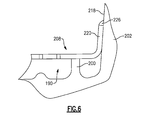
Figure 6 is a cross-sectional view taken along line 5-5 ofFigure 4B illustrating another embodiment. - The embodiments, examples and alternatives of the preceding paragraphs, the claims, or the following description and drawings, including any of their various aspects or respective individual features, may be taken independently or in any combination. Features described in connection with one embodiment are applicable to all embodiments, unless such features are incompatible.
-
Figure 1 schematically illustrates agas turbine engine 20. Thegas turbine engine 20 is disclosed herein as a two-spool turbofan that generally incorporates afan section 22, acompressor section 24, acombustor section 26 and aturbine section 28. Alternative engines might include an augmenter section (not shown) among other systems or features. Thefan section 22 drives air along a bypass flow path B in a bypass duct defined within anacelle 15, while thecompressor section 24 drives air along a core flow path C for compression and communication into thecombustor section 26 then expansion through theturbine section 28. Although depicted as a two-spool turbofan gas turbine engine in the disclosed non-limiting embodiment, it should be understood that the concepts described herein are not limited to use with two-spool turbofans as the teachings may be applied to other types of turbine engines including three-spool architectures. That is, the disclosed airfoils may be used for engine configurations such as, for example, direct fan drives, or two- or three-spool engines with a speed change mechanism coupling the fan with a compressor or a turbine sections. - The
exemplary engine 20 generally includes alow speed spool 30 and ahigh speed spool 32 mounted for rotation about an engine central longitudinal axis X relative to an enginestatic structure 36 viaseveral bearing systems 38. It should be understood that various bearingsystems 38 at various locations may alternatively or additionally be provided, and the location of bearingsystems 38 may be varied as appropriate to the application. - The
low speed spool 30 generally includes aninner shaft 40 that interconnects afan 42, a first (or low) pressure compressor 44 and a first (or low)pressure turbine 46. Theinner shaft 40 is connected to thefan 42 through a speed change mechanism, which in exemplarygas turbine engine 20 is illustrated as a gearedarchitecture 48 to drive thefan 42 at a lower speed than thelow speed spool 30. Thehigh speed spool 32 includes anouter shaft 50 that interconnects a second (or high)pressure compressor 52 and a second (or high)pressure turbine 54. Acombustor 56 is arranged inexemplary gas turbine 20 between thehigh pressure compressor 52 and thehigh pressure turbine 54. Amid-turbine frame 57 of the enginestatic structure 36 is arranged generally between thehigh pressure turbine 54 and thelow pressure turbine 46. Themid-turbine frame 57 furthersupports bearing systems 38 in theturbine section 28. Theinner shaft 40 and theouter shaft 50 are concentric and rotate via bearingsystems 38 about the engine central longitudinal axis X which is collinear with their longitudinal axes. - The core airflow is compressed by the low pressure compressor 44 then the
high pressure compressor 52, mixed and burned with fuel in thecombustor 56, then expanded over thehigh pressure turbine 54 andlow pressure turbine 46. Themid-turbine frame 57 includesairfoils 59 which are in the core airflow path C. Theturbines low speed spool 30 andhigh speed spool 32 in response to the expansion. It will be appreciated that each of the positions of thefan section 22,compressor section 24,combustor section 26,turbine section 28, and fandrive gear system 48 may be varied. For example,gear system 48 may be located aft ofcombustor section 26 or even aft ofturbine section 28, andfan section 22 may be positioned forward or aft of the location ofgear system 48. - The
engine 20 in one example is a high-bypass geared aircraft engine. In a further example, theengine 20 bypass ratio is greater than about six (6), with an example embodiment being greater than about ten (10), the gearedarchitecture 48 is an epicyclic gear train, such as a planetary gear system or other gear system, with a gear reduction ratio of greater than about 2.3 and thelow pressure turbine 46 has a pressure ratio that is greater than about five. In one disclosed embodiment, theengine 20 bypass ratio is greater than about ten (10:1), the fan diameter is significantly larger than that of the low pressure compressor 44, and thelow pressure turbine 46 has a pressure ratio that is greater than about five (5:1).Low pressure turbine 46 pressure ratio is pressure measured prior to inlet oflow pressure turbine 46 as related to the pressure at the outlet of thelow pressure turbine 46 prior to an exhaust nozzle. The gearedarchitecture 48 may be an epicyclic gear train, such as a planetary gear system or other gear system, with a gear reduction ratio of greater than about 2.3:1. It should be understood, however, that the above parameters are only exemplary of one embodiment of a geared architecture engine and that the present invention is applicable to other gas turbine engines including direct drive turbofans. - The example gas turbine engine includes the
fan 42 that comprises in one non-limiting embodiment less than about twenty-six (26) fan blades. In another non-limiting embodiment, thefan section 22 includes less than about twenty (20) fan blades. Moreover, in one disclosed embodiment thelow pressure turbine 46 includes no more than about six (6) turbine rotors schematically indicated at 34. In another non-limiting example embodiment thelow pressure turbine 46 includes about three (3) turbine rotors. A ratio between the number offan blades 42 and the number of low pressure turbine rotors is between about 3.3 and about 8.6. The examplelow pressure turbine 46 provides the driving power to rotate thefan section 22 and therefore the relationship between the number of turbine rotors 34 in thelow pressure turbine 46 and the number ofblades 42 in thefan section 22 disclose an examplegas turbine engine 20 with increased power transfer efficiency. - A significant amount of thrust is provided by the bypass flow B due to the high bypass ratio. The
fan section 22 of theengine 20 is designed for a particular flight condition -- typically cruise at about 0.8 Mach and about 35,000 feet (10,668 meters). The flight condition of 0.8 Mach and 35,000 ft (10,668 meters), with the engine at its best fuel consumption - also known as "bucket cruise Thrust Specific Fuel Consumption ('TSFC')" - is the industry standard parameter of lbm of fuel being burned divided by lbf of thrust the engine produces at that minimum point. "Low fan pressure ratio" is the pressure ratio across the fan blade alone, without a Fan Exit Guide Vane ("FEGV") system. The low fan pressure ratio as disclosed herein according to one non-limiting embodiment is less than about 1.55. In another non-limiting embodiment the low fan pressure ratio is less than about 1.45. In another non-limiting embodiment the low fan pressure ratio is from 1.1 to 1.45. "Low corrected fan tip speed" is the actual fan tip speed in ft/sec divided by an industry standard temperature correction of [(Tram °R) / (518.7 °R)]0.5. The "Low corrected fan tip speed" as disclosed herein according to one non-limiting embodiment is less than about 1200 ft / second (365.7 meters/second). - The example gas turbine engine includes the
fan 42 that comprises in one non-limiting embodiment less than about twenty-six (26) fan blades. In another non-limiting embodiment, thefan section 22 includes less than about twenty (20) fan blades. Moreover, in one disclosed embodiment thelow pressure turbine 46 includes no more than about six (6) turbine rotors schematically indicated at 34. In another non-limiting example embodiment thelow pressure turbine 46 includes about three (3) turbine rotors. A ratio between the number offan blades 42 and the number of low pressure turbine rotors is between about 3.3 and about 8.6. The examplelow pressure turbine 46 provides the driving power to rotate thefan section 22 and therefore the relationship between the number of turbine rotors 34 in thelow pressure turbine 46 and the number ofblades 42 in thefan section 22 disclose an examplegas turbine engine 20 with increased power transfer efficiency. - Referring to
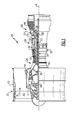
Figure 2 , a cross-sectional view through a highpressure turbine section 54 is illustrated. It should be understood that the disclosed vane may be used anywhere in the compressor section and/or the turbine section. In the example highpressure turbine section 54, first andsecond arrays vanes 60, 62 are axially spaced apart from one another. A first stage array 54b of circumferentially spacedturbine blades 64, mounted to arotor disk 68, is arranged axially between the first and second fixedvane arrays second stage array 54d of circumferentially spacedturbine blades 66 is arranged aft of thesecond array 54c of fixed vanes 62. - The turbine blades each include a
tip 80 adjacent to a blade outer air seal 70 of a case structure 72. The first andsecond stage arrays second stage arrays 54b, 54d of turbine blades are arranged within a core flow path C and are operatively connected to aspool 32. - In the example, each
vane 60 includes aninner platform 74 and anouter platform 76 respectively defining inner and outer flow paths. Theplatforms airfoil 78 extending in a radial direction. It should be understood that the turbine vanes may be discrete from one another or arranged in integrated clusters. Theairfoil 78 provides leading and trailingedges - The
airfoil 78 is provided between pressure (generally concave) and suction (generally convex) sides in an airfoil thickness direction, which is generally perpendicular to a chord-wise direction provided between the leading and trailingedges Multiple turbine vanes 60 are arranged circumferentially in a circumferential direction. Theairfoil 78 typically includes multiple film cooling holes (not shown). - In one example, the
first stage array 54a consists of 32turbine vanes 60, but the number may vary according to engine size. The turbine vanes 60 are constructed from a high strength, heat resistant material such as a nickel-based or cobalt-based superalloy, or of a high temperature, stress resistant ceramic or composite material. In cooled configurations, internal fluid passages and external cooling apertures provide for a combination of impingement and film cooling. Other cooling approaches may be used such as trip strips, pedestals or other convective cooling techniques. In addition, one or more thermal barrier coatings, abrasion-resistant coatings or other protective coatings may be applied to theturbine vane 60. - Referring to
Figure 2 , acooling cavity 88 is arranged between the enginestatic structure 36 and thevane 60. A coolingsource 86, such as bleed air from the compressor section, provides a cooling fluid to thecavity 88. Although thecavity 88 is illustrated as being arranged at theouter platform 76, it should be understood that the cavity may also be positioned at theinner platform 74. - The
airfoil 78 extends from a first side of theouter platform 76. Referring toFigures 3A and 3B , thevane 60 includes aplatform pocket 90 in a second side of the platform, for example, theouter platform 76. Animpingement plate 108 is secured to theouter platform 76 over thepocket 90 to enhance the cooling of theouter platform 76 during engine operation. - Referring to
Figures 4A-5 , aface 94 of theouter platform 76 includesmultiple protrusions 96 that extend into the platform pocket, which enhances cooling of theouter platform 76. Thepocket 90 is defined by aperimeter 98 provided by forward andaft rails lateral walls impingement plate 108 is secured to theouter platform 76 over thepocket 90 to at least one of the forward andaft rails lateral walls - The
impingement plate 108 includes acooling wall 110 that hasmultiple cooling holes 112, best shown inFigure 4B . Thecavity 88 fills with cooling fluid, which passes through the cooling holes 112 to impinge upon theface 94 and its associatedprotrusions 96. - The
face 94 includes aridge 107 that extends radially outward to circumscribe thecooling passage 92. Theimpingement plate 108 includes anopening 111, which surrounds thecooling passage 92 and seals against theridge 107. Thecavity 88 is in fluid communication with thecooling passage 92 to provide cooling fluid to theairfoil 78. - The
impingement plate 108 includeslateral flanges lateral walls wall 110 engages a recessedwall 105 that is recessed with respect to the adjacentlateral walls forward rail 100. Thelateral flanges cooling wall 110. - The
aft rail 102 includes aradial surface 118, and theimpingement plate 108 includes aradial flange 120 that extends radially and engages theradial surface 118. Theradial flange 120 is generally perpendicular to thecooling wall 110. In the example, theimpingement plate 108 is unsupported immediately beneath theradial flange 120 in the radial direction, eliminating the prior art shoulder in this area. This arrangement may also be provided at the forward rail, if desired. -
Welds lateral flanges radial flange 120 to thelateral walls aft rail 102. More or fewer welds may be used than illustrated. For example, a weld bead may be provided at theopening 111 and about the outer perimeter of theimpingement plate 108 to entirely seal the pocket 90 (except the cooling holes 112). - Referring to
Figure 6 , theimpingement plate 208 is arranged over thepocket 190. A portion of theimpingement plate 208 is supported by apedestal 200 arranged near theradial flange 220. Theradial flange 220 engages aradial surface 218 of theaft rail 202. If desired, aweld 226 can be used to secure theradial flange 220 to theradial surface 218. Thepedestal 200 sets the height of theimpingement plate 208 without significantly impacting the cooled area of thepocket 190. - The disclosed vane removes the shoulder adjacent to the forward or aft rail and has the impingement plate mate to the vertical (radial) face of the rail. This is accomplished by introducing a bend in the sheet metal that follows the transition from the lateral walls around the platform pocket up the face of the vertical rail. This construction enlarges the pocket to increase impingement cooling, minimizing uncooled mass adjacent to the rails.
- It should also be understood that although a particular component arrangement is disclosed in the illustrated embodiment, other arrangements will benefit herefrom. Although particular step sequences are shown, described, and claimed, it should be understood that steps may be performed in any order, separated or combined unless otherwise indicated and will still benefit from the present invention.
- Although the different examples have specific components shown in the illustrations, embodiments of this invention are not limited to those particular combinations. It is possible to use some of the components or features from one of the examples in combination with features or components from another one of the examples.
- Although an example embodiment has been disclosed, a worker of ordinary skill in this art would recognize that certain modifications would come within the scope of the claims. For that reason, the following claims should be studied to determine their true scope and content.
Claims (15)
- A stator vane (60) for a gas turbine engine comprising:an airfoil (78) extending radially from an first side of a platform (76), a pocket (90;190) provided in the platform (76) on a second side opposite the airfoil (78), forward and aft rails (100,102) extending from the second side of the platform (76), one of the forward and aft rails (100,102) including a radial surface (118;218); andan impingement plate (108;208) secured to the platform (76) over the pocket (90;190), the impingement plate (108;208) including a radial wall (120;220) engaging the radial surface (118;218).
- The stator vane according to claim 1, wherein the pocket (90) is circumscribed by a perimeter (98), the perimeter (98) provided by the forward and aft rails (100,102) and spaced apart lateral walls (104,106) joining the forward and aft rails (100,102).
- The stator vane according to claim 2, comprising a cooling passage (92) that extends through the airfoil (78) to the second side, and the impingement plate (90) includes an opening (111) aligned with the cooling passage (92) to provide fluid communication there between.
- The stator vane according to claim 3, wherein the second side includes a ridge (101) circumscribing the cooling passage (92) and engaging the impingement plate (90) near the opening (111).
- The stator vane according to claim 3 or 4, wherein the impingement plate (108) includes a cooling surface that provides the opening, and the cooling surface includes multiple cooling holes (112) facing the second side, wherein, optionally, the second side includes multiple protrusions (96) arranged beneath the multiple cooling holes (112).
- The stator vane according to any of claims 2 to 5, wherein the second side includes a recessed wall (105) adjoining the lateral walls (104,106) and the other of the forward and aft rails (100,102), the impingement plate (90) engaging the recessed wall (105).
- The stator vane according to any of claims 2 to 6, wherein the impingement plate includes lateral flanges (114,116) engaging the lateral walls (104,106).
- The stator vane according to claim 7, wherein the lateral flanges (114,116) are welded to the lateral walls (164,106).
- The stator vane according to claim 7 or 8, wherein the radial wall (120;220) is generally perpendicular to the lateral flanges (114,116).
- The stator vane according to any preceding claim, wherein the radial wall (120;220) is welded to the radial surface (118;218).
- The stator vane according to any preceding claim, wherein the radial surface (118;218) is provided on the aft rail (102,202).
- The stator vane according to any preceding claim, wherein the impingement plate (90; 190) is unsupported immediately beneath the radial wall (120;220) in the radial direction.
- The stator vane according to any preceding claim, wherein the impingement plate (190) is supported by at least one pedestal (200) near the radial wall (220) in the radial direction.
- The stator vane according to any preceding claim, comprising inner and outer platforms (74,76) joined by the airfoil (78), wherein the platform (76) is the outer platform, wherein, optionally, the stator vane (60) is a turbine vane.
- A gas turbine engine (20) comprising:engine static structure;compressor and turbine sections (24,28), one of the compressor and turbine sections including
a stator vane (60) according to any preceding claim arranged in one of the compressor and turbine sections (24,28), the pocket (90; 190) provided in the platform (76) on the second side opposite the airfoil (78) that is in fluid communication with a cavity provided between the platform (76) and the engine static structure.
Applications Claiming Priority (1)
| Application Number | Priority Date | Filing Date | Title |
|---|---|---|---|
| US201461975265P | 2014-04-04 | 2014-04-04 |
Publications (2)
| Publication Number | Publication Date |
|---|---|
| EP2927430A1 true EP2927430A1 (en) | 2015-10-07 |
| EP2927430B1 EP2927430B1 (en) | 2019-08-07 |
Family
ID=52780481
Family Applications (1)
| Application Number | Title | Priority Date | Filing Date |
|---|---|---|---|
| EP15162139.8A Active EP2927430B1 (en) | 2014-04-04 | 2015-04-01 | Stator vane with a cooled platform for a gas turbine engine |
Country Status (2)
| Country | Link |
|---|---|
| US (1) | US9995157B2 (en) |
| EP (1) | EP2927430B1 (en) |
Cited By (4)
| Publication number | Priority date | Publication date | Assignee | Title |
|---|---|---|---|---|
| EP3170979A1 (en) * | 2015-11-19 | 2017-05-24 | United Technologies Corporation | Turbine component including mixed cooling nub feature |
| CN107461225A (en) * | 2016-06-02 | 2017-12-12 | 通用电气公司 | Nozzle cooling system for gas-turbine unit |
| EP3450685A1 (en) * | 2017-08-02 | 2019-03-06 | United Technologies Corporation | Gas turbine engine component |
| EP3543464A1 (en) * | 2018-01-31 | 2019-09-25 | United Technologies Corporation | Dual cavity baffle |
Families Citing this family (9)
| Publication number | Priority date | Publication date | Assignee | Title |
|---|---|---|---|---|
| US11339668B2 (en) * | 2018-10-29 | 2022-05-24 | Chromalloy Gas Turbine Llc | Method and apparatus for improving cooling of a turbine shroud |
| US11021966B2 (en) * | 2019-04-24 | 2021-06-01 | Raytheon Technologies Corporation | Vane core assemblies and methods |
| JP6799702B1 (en) * | 2020-03-19 | 2020-12-16 | 三菱パワー株式会社 | Static blade and gas turbine |
| US11808176B2 (en) * | 2021-05-04 | 2023-11-07 | Rtx Corporation | CMC vane sealing arrangement |
| JP7674511B2 (en) * | 2021-11-29 | 2025-05-09 | 三菱重工業株式会社 | Turbine vanes |
| US11536143B1 (en) | 2021-12-22 | 2022-12-27 | Rolls-Royce North American Technologies Inc. | Endwall cooling scheme |
| US11635000B1 (en) * | 2021-12-23 | 2023-04-25 | Rolls-Royce Corporation | Endwall directional cooling |
| JP2024123848A (en) * | 2023-03-02 | 2024-09-12 | 三菱重工業株式会社 | Turbine vane and gas turbine |
| FR3150236B1 (en) * | 2023-06-23 | 2026-04-24 | Safran Aircraft Engines | Turbine distributor |
Citations (5)
| Publication number | Priority date | Publication date | Assignee | Title |
|---|---|---|---|---|
| GB1322801A (en) * | 1969-12-01 | 1973-07-11 | Gen Electric | Vane assembly |
| JPH11257003A (en) * | 1998-03-06 | 1999-09-21 | Mitsubishi Heavy Ind Ltd | Impingement cooling device |
| DE102005024696A1 (en) * | 2004-06-15 | 2006-01-05 | Alstom Technology Ltd | Component part of especially turbo-engine has protective shroud installed around sleeve element to protect section of sleeve element protruding from cooling passage against effects of surrounding flow |
| US20100266386A1 (en) * | 2009-04-21 | 2010-10-21 | Mark Broomer | Flange cooled turbine nozzle |
| EP2469034A2 (en) * | 2010-12-22 | 2012-06-27 | United Technologies Corporation | Turbine stator vane having a platform with a cooling circuit and corresponding manufacturing method |
Family Cites Families (11)
| Publication number | Priority date | Publication date | Assignee | Title |
|---|---|---|---|---|
| US3800864A (en) * | 1972-09-05 | 1974-04-02 | Gen Electric | Pin-fin cooling system |
| US4712979A (en) | 1985-11-13 | 1987-12-15 | The United States Of America As Represented By The Secretary Of The Air Force | Self-retained platform cooling plate for turbine vane |
| US5413458A (en) | 1994-03-29 | 1995-05-09 | United Technologies Corporation | Turbine vane with a platform cavity having a double feed for cooling fluid |
| ES2144147T3 (en) | 1994-11-10 | 2000-06-01 | Siemens Westinghouse Power | GAS TURBINE ALABE WITH REFRIGERATED INTERNAL JAM. |
| US6386825B1 (en) | 2000-04-11 | 2002-05-14 | General Electric Company | Apparatus and methods for impingement cooling of a side wall of a turbine nozzle segment |
| DE50210878D1 (en) | 2001-07-05 | 2007-10-25 | Alstom Technology Ltd | Method for mounting a baffle plate |
| US7862291B2 (en) | 2007-02-08 | 2011-01-04 | United Technologies Corporation | Gas turbine engine component cooling scheme |
| CH700319A1 (en) * | 2009-01-30 | 2010-07-30 | Alstom Technology Ltd | Chilled component for a gas turbine. |
| EP2397653A1 (en) * | 2010-06-17 | 2011-12-21 | Siemens Aktiengesellschaft | Platform segment for supporting a nozzle guide vane for a gas turbine and method of cooling thereof |
| US9500099B2 (en) | 2012-07-02 | 2016-11-22 | United Techologies Corporation | Cover plate for a component of a gas turbine engine |
| US9657642B2 (en) | 2014-03-27 | 2017-05-23 | Honeywell International Inc. | Turbine sections of gas turbine engines with dual use of cooling air |
-
2015
- 2015-04-01 EP EP15162139.8A patent/EP2927430B1/en active Active
- 2015-04-01 US US14/675,824 patent/US9995157B2/en active Active
Patent Citations (5)
| Publication number | Priority date | Publication date | Assignee | Title |
|---|---|---|---|---|
| GB1322801A (en) * | 1969-12-01 | 1973-07-11 | Gen Electric | Vane assembly |
| JPH11257003A (en) * | 1998-03-06 | 1999-09-21 | Mitsubishi Heavy Ind Ltd | Impingement cooling device |
| DE102005024696A1 (en) * | 2004-06-15 | 2006-01-05 | Alstom Technology Ltd | Component part of especially turbo-engine has protective shroud installed around sleeve element to protect section of sleeve element protruding from cooling passage against effects of surrounding flow |
| US20100266386A1 (en) * | 2009-04-21 | 2010-10-21 | Mark Broomer | Flange cooled turbine nozzle |
| EP2469034A2 (en) * | 2010-12-22 | 2012-06-27 | United Technologies Corporation | Turbine stator vane having a platform with a cooling circuit and corresponding manufacturing method |
Cited By (6)
| Publication number | Priority date | Publication date | Assignee | Title |
|---|---|---|---|---|
| EP3170979A1 (en) * | 2015-11-19 | 2017-05-24 | United Technologies Corporation | Turbine component including mixed cooling nub feature |
| US10208671B2 (en) | 2015-11-19 | 2019-02-19 | United Technologies Corporation | Turbine component including mixed cooling nub feature |
| CN107461225A (en) * | 2016-06-02 | 2017-12-12 | 通用电气公司 | Nozzle cooling system for gas-turbine unit |
| EP3450685A1 (en) * | 2017-08-02 | 2019-03-06 | United Technologies Corporation | Gas turbine engine component |
| US10746033B2 (en) | 2017-08-02 | 2020-08-18 | Raytheon Technologies Corporation | Gas turbine engine component |
| EP3543464A1 (en) * | 2018-01-31 | 2019-09-25 | United Technologies Corporation | Dual cavity baffle |
Also Published As
| Publication number | Publication date |
|---|---|
| EP2927430B1 (en) | 2019-08-07 |
| US20150285086A1 (en) | 2015-10-08 |
| US9995157B2 (en) | 2018-06-12 |
Similar Documents
| Publication | Publication Date | Title |
|---|---|---|
| EP2927430B1 (en) | Stator vane with a cooled platform for a gas turbine engine | |
| US10808546B2 (en) | Gas turbine engine airfoil trailing edge suction side cooling | |
| US20090238683A1 (en) | Vane with integral inner air seal | |
| US9334755B2 (en) | Airfoil with variable trip strip height | |
| EP3009616B1 (en) | Gas turbine component with platform cooling | |
| US20160208620A1 (en) | Gas turbine engine airfoil turbulator for airfoil creep resistance | |
| EP2937511B1 (en) | Gas turbine engine airfoil cooling passage configuration | |
| EP3514332A1 (en) | Dual-wall impingement cavity for components of gas turbine engines | |
| EP3444435B1 (en) | Expansion seal for airfoil for gas turbine engine | |
| EP3009600A1 (en) | Gas turbine engine turbine blade with cooled tip | |
| EP3620613B1 (en) | Integrated seal and wear liner | |
| US10584596B2 (en) | Gas turbine engine components having internal cooling features | |
| EP3039247B1 (en) | Gas turbine engine airfoil crossover and pedestal rib cooling arrangement | |
| EP2995778B1 (en) | Method and assembly for reducing secondary heat in a gas turbine engine | |
| EP3059391A1 (en) | Gas turbine engine turbine blade cooling using upstream stator vane | |
| EP2938831B1 (en) | Gas turbine engine turbine blade tip cooling | |
| EP3578759B1 (en) | Airfoil and corresponding method of directing a cooling flow | |
| US10815794B2 (en) | Baffle for components of gas turbine engines | |
| EP3581762B1 (en) | Platform cooling arrangement for a gas turbine engine |
Legal Events
| Date | Code | Title | Description |
|---|---|---|---|
| PUAI | Public reference made under article 153(3) epc to a published international application that has entered the european phase |
Free format text: ORIGINAL CODE: 0009012 |
|
| AK | Designated contracting states |
Kind code of ref document: A1 Designated state(s): AL AT BE BG CH CY CZ DE DK EE ES FI FR GB GR HR HU IE IS IT LI LT LU LV MC MK MT NL NO PL PT RO RS SE SI SK SM TR |
|
| AX | Request for extension of the european patent |
Extension state: BA ME |
|
| 17P | Request for examination filed |
Effective date: 20160407 |
|
| RBV | Designated contracting states (corrected) |
Designated state(s): AL AT BE BG CH CY CZ DE DK EE ES FI FR GB GR HR HU IE IS IT LI LT LU LV MC MK MT NL NO PL PT RO RS SE SI SK SM TR |
|
| RAP1 | Party data changed (applicant data changed or rights of an application transferred) |
Owner name: UNITED TECHNOLOGIES CORPORATION |
|
| STAA | Information on the status of an ep patent application or granted ep patent |
Free format text: STATUS: EXAMINATION IS IN PROGRESS |
|
| 17Q | First examination report despatched |
Effective date: 20180323 |
|
| GRAP | Despatch of communication of intention to grant a patent |
Free format text: ORIGINAL CODE: EPIDOSNIGR1 |
|
| STAA | Information on the status of an ep patent application or granted ep patent |
Free format text: STATUS: GRANT OF PATENT IS INTENDED |
|
| INTG | Intention to grant announced |
Effective date: 20190214 |
|
| GRAS | Grant fee paid |
Free format text: ORIGINAL CODE: EPIDOSNIGR3 |
|
| GRAA | (expected) grant |
Free format text: ORIGINAL CODE: 0009210 |
|
| STAA | Information on the status of an ep patent application or granted ep patent |
Free format text: STATUS: THE PATENT HAS BEEN GRANTED |
|
| AK | Designated contracting states |
Kind code of ref document: B1 Designated state(s): AL AT BE BG CH CY CZ DE DK EE ES FI FR GB GR HR HU IE IS IT LI LT LU LV MC MK MT NL NO PL PT RO RS SE SI SK SM TR |
|
| REG | Reference to a national code |
Ref country code: GB Ref legal event code: FG4D |
|
| REG | Reference to a national code |
Ref country code: CH Ref legal event code: EP Ref country code: AT Ref legal event code: REF Ref document number: 1164178 Country of ref document: AT Kind code of ref document: T Effective date: 20190815 |
|
| REG | Reference to a national code |
Ref country code: DE Ref legal event code: R096 Ref document number: 602015035092 Country of ref document: DE |
|
| REG | Reference to a national code |
Ref country code: IE Ref legal event code: FG4D |
|
| REG | Reference to a national code |
Ref country code: NL Ref legal event code: MP Effective date: 20190807 |
|
| REG | Reference to a national code |
Ref country code: LT Ref legal event code: MG4D |
|
| PG25 | Lapsed in a contracting state [announced via postgrant information from national office to epo] |
Ref country code: FI Free format text: LAPSE BECAUSE OF FAILURE TO SUBMIT A TRANSLATION OF THE DESCRIPTION OR TO PAY THE FEE WITHIN THE PRESCRIBED TIME-LIMIT Effective date: 20190807 Ref country code: NL Free format text: LAPSE BECAUSE OF FAILURE TO SUBMIT A TRANSLATION OF THE DESCRIPTION OR TO PAY THE FEE WITHIN THE PRESCRIBED TIME-LIMIT Effective date: 20190807 Ref country code: LT Free format text: LAPSE BECAUSE OF FAILURE TO SUBMIT A TRANSLATION OF THE DESCRIPTION OR TO PAY THE FEE WITHIN THE PRESCRIBED TIME-LIMIT Effective date: 20190807 Ref country code: HR Free format text: LAPSE BECAUSE OF FAILURE TO SUBMIT A TRANSLATION OF THE DESCRIPTION OR TO PAY THE FEE WITHIN THE PRESCRIBED TIME-LIMIT Effective date: 20190807 Ref country code: PT Free format text: LAPSE BECAUSE OF FAILURE TO SUBMIT A TRANSLATION OF THE DESCRIPTION OR TO PAY THE FEE WITHIN THE PRESCRIBED TIME-LIMIT Effective date: 20191209 Ref country code: BG Free format text: LAPSE BECAUSE OF FAILURE TO SUBMIT A TRANSLATION OF THE DESCRIPTION OR TO PAY THE FEE WITHIN THE PRESCRIBED TIME-LIMIT Effective date: 20191107 Ref country code: SE Free format text: LAPSE BECAUSE OF FAILURE TO SUBMIT A TRANSLATION OF THE DESCRIPTION OR TO PAY THE FEE WITHIN THE PRESCRIBED TIME-LIMIT Effective date: 20190807 Ref country code: NO Free format text: LAPSE BECAUSE OF FAILURE TO SUBMIT A TRANSLATION OF THE DESCRIPTION OR TO PAY THE FEE WITHIN THE PRESCRIBED TIME-LIMIT Effective date: 20191107 |
|
| REG | Reference to a national code |
Ref country code: AT Ref legal event code: MK05 Ref document number: 1164178 Country of ref document: AT Kind code of ref document: T Effective date: 20190807 |
|
| PG25 | Lapsed in a contracting state [announced via postgrant information from national office to epo] |
Ref country code: IS Free format text: LAPSE BECAUSE OF FAILURE TO SUBMIT A TRANSLATION OF THE DESCRIPTION OR TO PAY THE FEE WITHIN THE PRESCRIBED TIME-LIMIT Effective date: 20191207 Ref country code: ES Free format text: LAPSE BECAUSE OF FAILURE TO SUBMIT A TRANSLATION OF THE DESCRIPTION OR TO PAY THE FEE WITHIN THE PRESCRIBED TIME-LIMIT Effective date: 20190807 Ref country code: AL Free format text: LAPSE BECAUSE OF FAILURE TO SUBMIT A TRANSLATION OF THE DESCRIPTION OR TO PAY THE FEE WITHIN THE PRESCRIBED TIME-LIMIT Effective date: 20190807 Ref country code: GR Free format text: LAPSE BECAUSE OF FAILURE TO SUBMIT A TRANSLATION OF THE DESCRIPTION OR TO PAY THE FEE WITHIN THE PRESCRIBED TIME-LIMIT Effective date: 20191108 Ref country code: LV Free format text: LAPSE BECAUSE OF FAILURE TO SUBMIT A TRANSLATION OF THE DESCRIPTION OR TO PAY THE FEE WITHIN THE PRESCRIBED TIME-LIMIT Effective date: 20190807 Ref country code: RS Free format text: LAPSE BECAUSE OF FAILURE TO SUBMIT A TRANSLATION OF THE DESCRIPTION OR TO PAY THE FEE WITHIN THE PRESCRIBED TIME-LIMIT Effective date: 20190807 |
|
| PG25 | Lapsed in a contracting state [announced via postgrant information from national office to epo] |
Ref country code: TR Free format text: LAPSE BECAUSE OF FAILURE TO SUBMIT A TRANSLATION OF THE DESCRIPTION OR TO PAY THE FEE WITHIN THE PRESCRIBED TIME-LIMIT Effective date: 20190807 |
|
| PG25 | Lapsed in a contracting state [announced via postgrant information from national office to epo] |
Ref country code: PL Free format text: LAPSE BECAUSE OF FAILURE TO SUBMIT A TRANSLATION OF THE DESCRIPTION OR TO PAY THE FEE WITHIN THE PRESCRIBED TIME-LIMIT Effective date: 20190807 Ref country code: AT Free format text: LAPSE BECAUSE OF FAILURE TO SUBMIT A TRANSLATION OF THE DESCRIPTION OR TO PAY THE FEE WITHIN THE PRESCRIBED TIME-LIMIT Effective date: 20190807 Ref country code: EE Free format text: LAPSE BECAUSE OF FAILURE TO SUBMIT A TRANSLATION OF THE DESCRIPTION OR TO PAY THE FEE WITHIN THE PRESCRIBED TIME-LIMIT Effective date: 20190807 Ref country code: DK Free format text: LAPSE BECAUSE OF FAILURE TO SUBMIT A TRANSLATION OF THE DESCRIPTION OR TO PAY THE FEE WITHIN THE PRESCRIBED TIME-LIMIT Effective date: 20190807 Ref country code: RO Free format text: LAPSE BECAUSE OF FAILURE TO SUBMIT A TRANSLATION OF THE DESCRIPTION OR TO PAY THE FEE WITHIN THE PRESCRIBED TIME-LIMIT Effective date: 20190807 Ref country code: IT Free format text: LAPSE BECAUSE OF FAILURE TO SUBMIT A TRANSLATION OF THE DESCRIPTION OR TO PAY THE FEE WITHIN THE PRESCRIBED TIME-LIMIT Effective date: 20190807 |
|
| PG25 | Lapsed in a contracting state [announced via postgrant information from national office to epo] |
Ref country code: IS Free format text: LAPSE BECAUSE OF FAILURE TO SUBMIT A TRANSLATION OF THE DESCRIPTION OR TO PAY THE FEE WITHIN THE PRESCRIBED TIME-LIMIT Effective date: 20200224 Ref country code: SM Free format text: LAPSE BECAUSE OF FAILURE TO SUBMIT A TRANSLATION OF THE DESCRIPTION OR TO PAY THE FEE WITHIN THE PRESCRIBED TIME-LIMIT Effective date: 20190807 Ref country code: SK Free format text: LAPSE BECAUSE OF FAILURE TO SUBMIT A TRANSLATION OF THE DESCRIPTION OR TO PAY THE FEE WITHIN THE PRESCRIBED TIME-LIMIT Effective date: 20190807 Ref country code: CZ Free format text: LAPSE BECAUSE OF FAILURE TO SUBMIT A TRANSLATION OF THE DESCRIPTION OR TO PAY THE FEE WITHIN THE PRESCRIBED TIME-LIMIT Effective date: 20190807 |
|
| REG | Reference to a national code |
Ref country code: DE Ref legal event code: R097 Ref document number: 602015035092 Country of ref document: DE |
|
| PLBE | No opposition filed within time limit |
Free format text: ORIGINAL CODE: 0009261 |
|
| STAA | Information on the status of an ep patent application or granted ep patent |
Free format text: STATUS: NO OPPOSITION FILED WITHIN TIME LIMIT |
|
| PG2D | Information on lapse in contracting state deleted |
Ref country code: IS |
|
| 26N | No opposition filed |
Effective date: 20200603 |
|
| PG25 | Lapsed in a contracting state [announced via postgrant information from national office to epo] |
Ref country code: SI Free format text: LAPSE BECAUSE OF FAILURE TO SUBMIT A TRANSLATION OF THE DESCRIPTION OR TO PAY THE FEE WITHIN THE PRESCRIBED TIME-LIMIT Effective date: 20190807 |
|
| PG25 | Lapsed in a contracting state [announced via postgrant information from national office to epo] |
Ref country code: MC Free format text: LAPSE BECAUSE OF FAILURE TO SUBMIT A TRANSLATION OF THE DESCRIPTION OR TO PAY THE FEE WITHIN THE PRESCRIBED TIME-LIMIT Effective date: 20190807 |
|
| REG | Reference to a national code |
Ref country code: CH Ref legal event code: PL |
|
| PG25 | Lapsed in a contracting state [announced via postgrant information from national office to epo] |
Ref country code: LU Free format text: LAPSE BECAUSE OF NON-PAYMENT OF DUE FEES Effective date: 20200401 Ref country code: LI Free format text: LAPSE BECAUSE OF NON-PAYMENT OF DUE FEES Effective date: 20200430 Ref country code: CH Free format text: LAPSE BECAUSE OF NON-PAYMENT OF DUE FEES Effective date: 20200430 |
|
| REG | Reference to a national code |
Ref country code: BE Ref legal event code: MM Effective date: 20200430 |
|
| PG25 | Lapsed in a contracting state [announced via postgrant information from national office to epo] |
Ref country code: BE Free format text: LAPSE BECAUSE OF NON-PAYMENT OF DUE FEES Effective date: 20200430 |
|
| PG25 | Lapsed in a contracting state [announced via postgrant information from national office to epo] |
Ref country code: IE Free format text: LAPSE BECAUSE OF NON-PAYMENT OF DUE FEES Effective date: 20200401 |
|
| PG25 | Lapsed in a contracting state [announced via postgrant information from national office to epo] |
Ref country code: MT Free format text: LAPSE BECAUSE OF FAILURE TO SUBMIT A TRANSLATION OF THE DESCRIPTION OR TO PAY THE FEE WITHIN THE PRESCRIBED TIME-LIMIT Effective date: 20190807 Ref country code: CY Free format text: LAPSE BECAUSE OF FAILURE TO SUBMIT A TRANSLATION OF THE DESCRIPTION OR TO PAY THE FEE WITHIN THE PRESCRIBED TIME-LIMIT Effective date: 20190807 |
|
| PG25 | Lapsed in a contracting state [announced via postgrant information from national office to epo] |
Ref country code: MK Free format text: LAPSE BECAUSE OF FAILURE TO SUBMIT A TRANSLATION OF THE DESCRIPTION OR TO PAY THE FEE WITHIN THE PRESCRIBED TIME-LIMIT Effective date: 20190807 |
|
| REG | Reference to a national code |
Ref country code: DE Ref legal event code: R081 Ref document number: 602015035092 Country of ref document: DE Owner name: RAYTHEON TECHNOLOGIES CORPORATION (N.D.GES.D.S, US Free format text: FORMER OWNER: UNITED TECHNOLOGIES CORPORATION, FARMINGTON, CONN., US Ref country code: DE Ref legal event code: R081 Ref document number: 602015035092 Country of ref document: DE Owner name: RTX CORPORATION (N.D.GES.D. STAATES DELAWARE),, US Free format text: FORMER OWNER: UNITED TECHNOLOGIES CORPORATION, FARMINGTON, CONN., US |
|
| P01 | Opt-out of the competence of the unified patent court (upc) registered |
Effective date: 20230520 |
|
| PGFP | Annual fee paid to national office [announced via postgrant information from national office to epo] |
Ref country code: DE Payment date: 20250319 Year of fee payment: 11 |
|
| REG | Reference to a national code |
Ref country code: DE Ref legal event code: R081 Ref document number: 602015035092 Country of ref document: DE Owner name: RTX CORPORATION (N.D.GES.D. STAATES DELAWARE),, US Free format text: FORMER OWNER: RAYTHEON TECHNOLOGIES CORPORATION (N.D.GES.D.STAATES DELAWARE), ARLINGTON, VA, US |
|
| PGFP | Annual fee paid to national office [announced via postgrant information from national office to epo] |
Ref country code: GB Payment date: 20260319 Year of fee payment: 12 |
|
| PGFP | Annual fee paid to national office [announced via postgrant information from national office to epo] |
Ref country code: FR Payment date: 20260319 Year of fee payment: 12 |