EP2927406B1 - Glass door and hinge arrangement - Google Patents
Glass door and hinge arrangement Download PDFInfo
- Publication number
- EP2927406B1 EP2927406B1 EP15168730.8A EP15168730A EP2927406B1 EP 2927406 B1 EP2927406 B1 EP 2927406B1 EP 15168730 A EP15168730 A EP 15168730A EP 2927406 B1 EP2927406 B1 EP 2927406B1
- Authority
- EP
- European Patent Office
- Prior art keywords
- door
- cup
- hinge
- plate
- shaped part
- Prior art date
- Legal status (The legal status is an assumption and is not a legal conclusion. Google has not performed a legal analysis and makes no representation as to the accuracy of the status listed.)
- Active
Links
- 239000011521 glass Substances 0.000 title claims description 12
- 230000002093 peripheral effect Effects 0.000 claims description 3
- 229920003023 plastic Polymers 0.000 description 2
- 239000004033 plastic Substances 0.000 description 2
- XAGFODPZIPBFFR-UHFFFAOYSA-N aluminium Chemical compound [Al] XAGFODPZIPBFFR-UHFFFAOYSA-N 0.000 description 1
- 229910052782 aluminium Inorganic materials 0.000 description 1
- 239000004411 aluminium Substances 0.000 description 1
- 238000004519 manufacturing process Methods 0.000 description 1
- 239000000463 material Substances 0.000 description 1
- 238000010079 rubber tapping Methods 0.000 description 1
- 125000006850 spacer group Chemical group 0.000 description 1
Images

Classifications
-
- E—FIXED CONSTRUCTIONS
- E05—LOCKS; KEYS; WINDOW OR DOOR FITTINGS; SAFES
- E05D—HINGES OR SUSPENSION DEVICES FOR DOORS, WINDOWS OR WINGS
- E05D5/00—Construction of single parts, e.g. the parts for attachment
- E05D5/02—Parts for attachment, e.g. flaps
- E05D5/0246—Parts for attachment, e.g. flaps for attachment to glass panels
-
- E—FIXED CONSTRUCTIONS
- E05—LOCKS; KEYS; WINDOW OR DOOR FITTINGS; SAFES
- E05Y—INDEXING SCHEME ASSOCIATED WITH SUBCLASSES E05D AND E05F, RELATING TO CONSTRUCTION ELEMENTS, ELECTRIC CONTROL, POWER SUPPLY, POWER SIGNAL OR TRANSMISSION, USER INTERFACES, MOUNTING OR COUPLING, DETAILS, ACCESSORIES, AUXILIARY OPERATIONS NOT OTHERWISE PROVIDED FOR, APPLICATION THEREOF
- E05Y2600/00—Mounting or coupling arrangements for elements provided for in this subclass
- E05Y2600/50—Mounting methods; Positioning
- E05Y2600/502—Clamping
-
- E—FIXED CONSTRUCTIONS
- E05—LOCKS; KEYS; WINDOW OR DOOR FITTINGS; SAFES
- E05Y—INDEXING SCHEME ASSOCIATED WITH SUBCLASSES E05D AND E05F, RELATING TO CONSTRUCTION ELEMENTS, ELECTRIC CONTROL, POWER SUPPLY, POWER SIGNAL OR TRANSMISSION, USER INTERFACES, MOUNTING OR COUPLING, DETAILS, ACCESSORIES, AUXILIARY OPERATIONS NOT OTHERWISE PROVIDED FOR, APPLICATION THEREOF
- E05Y2800/00—Details, accessories and auxiliary operations not otherwise provided for
- E05Y2800/26—Form or shape
- E05Y2800/292—Form or shape having apertures
-
- E—FIXED CONSTRUCTIONS
- E05—LOCKS; KEYS; WINDOW OR DOOR FITTINGS; SAFES
- E05Y—INDEXING SCHEME ASSOCIATED WITH SUBCLASSES E05D AND E05F, RELATING TO CONSTRUCTION ELEMENTS, ELECTRIC CONTROL, POWER SUPPLY, POWER SIGNAL OR TRANSMISSION, USER INTERFACES, MOUNTING OR COUPLING, DETAILS, ACCESSORIES, AUXILIARY OPERATIONS NOT OTHERWISE PROVIDED FOR, APPLICATION THEREOF
- E05Y2900/00—Application of doors, windows, wings or fittings thereof
-
- E—FIXED CONSTRUCTIONS
- E05—LOCKS; KEYS; WINDOW OR DOOR FITTINGS; SAFES
- E05Y—INDEXING SCHEME ASSOCIATED WITH SUBCLASSES E05D AND E05F, RELATING TO CONSTRUCTION ELEMENTS, ELECTRIC CONTROL, POWER SUPPLY, POWER SIGNAL OR TRANSMISSION, USER INTERFACES, MOUNTING OR COUPLING, DETAILS, ACCESSORIES, AUXILIARY OPERATIONS NOT OTHERWISE PROVIDED FOR, APPLICATION THEREOF
- E05Y2900/00—Application of doors, windows, wings or fittings thereof
- E05Y2900/10—Application of doors, windows, wings or fittings thereof for buildings or parts thereof
- E05Y2900/13—Type of wing
- E05Y2900/132—Doors
Definitions
- This invention relates to a door, such as a cabinet door, fitted with a hinge arrangement.
- a hinge part typically includes a shallow, hollow cylinder, suitable for lodging in a round through-hole in the door.
- the hinge part is screwed to an external plate located on the outside of the door, clamping the door between the hinge part and the external plate.
- hinges are suitable for lightweight glass doors, e.g. those less than about 8 mm in thickness. However, they cannot support heavier glass doors.
- WO 97/43511 A1 describes a glass door according to the preamble of claim 1.
- DE 85 36 840 U1 and US 2004/020130 describe arrangements in which a hinge plate has a recess in an edge thereof.
- the present invention provides a glass door according to claim 1.
- the hinge part can advantageously be that of a known cabinet hinge.
- the door is thicker than the external depth of the cup-shaped part of the hinge, which is inserted into a recess in the door.
- the invention surprisingly uses such hinge parts in doors that are thinner than this depth, the additional depth being accommodated in the recess in the external plate.
- the cup-shaped part may be generally cylindrical.
- the recess may also be cylindrical, with a diameter essentially matching the external diameter of the cup-shaped part.
- the hinge part includes at least one hole and the plate includes at least one screw recess arranged to register with the respective hole(s), for screwing the hinge part to the plate, to clamp the door therebetween.
- the hole(s) is located in a peripheral flange of the hinge part.
- two holes may be provided.
- the arrangement may include screw sleeves locatable in the door, between the holes and the screw recesses.
- An inner gasket may be provided, locatable between the hinge part and the door.
- An outer gasket may be locatable between the door and the plate.
- the inner and/or outer gasket may include one or more openings through which the cup-shaped part and/or the screws can pass.
- the door has the opening through which the cup-shaped part extends.
- the opening has a shape that is generally circular but has one or more extensions for the screw(s).
- a hinge part 1 is generally of conventional shape, comprising a hollow, generally cylindrical cup 2 and a peripheral flange 3. However the depth of the cup 2 is significantly greater than that of a known glass door hinge.
- the hinge part 1 can be formed of metallic or plastics material.
- the hinge part 1 is screwed to an external plate 4, e.g. of aluminium, by means of screws 5.
- the external plate has a milled circular recess 6 sized to receive that part of the cup 2 that protrudes through a glass door 7.
- the internal diameter of the recess 6 matches the external diameter of the cup 2, whilst the depth of the recess 6 is at least as great as the difference between the external depth of the cup 2 and the thickness of the door 7, and preferably approximately equal to that difference.
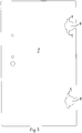
- the cup 2 extends through an opening 8 in the door 7, shown in Figure 3 .
- This opening is generally circular, with two extensions 9 extending generally in the line of a chord of the circle.
- the opening 8 communicates with an inner edge of the door 7.
- the screws 5 are screwed through cylindrical plastics spacers 10, housed in the extensions 9, and into threaded screw recesses 11 provided in the external plate 4 above and below the recess 6.
- An inner gasket 12 is located between the flange 3 and the door 7. This may have holes for the screws 5 and may extend around the cup 2 on one side thereof.
- An outer gasket 13 is located between the door 7 and the external plate 4. This has a central circular hole for the cup 2. It may also be provided with holes for the screws 5. The pre-made holes for screws in both gaskets 12, 13 are optional, particularly if the machine screws shown are replaced by self-tapping screws.
- the bottom of the cup is flush with the external surface of the door.
- the cup 2 extends into the recess 6, supporting the external plate 4 more securely and clamping the door more efficiently. This means that thicker, heavier doors can be used with a simple hinge.
Landscapes
- Engineering & Computer Science (AREA)
- Mechanical Engineering (AREA)
- Hinges (AREA)
Description
- This invention relates to a door, such as a cabinet door, fitted with a hinge arrangement.
- Known hinges for glass cabinet doors, similar to "European" cabinet hinges for wooden doors, are sold by Häfele GmbH & Co KG and by Arturo Salice SpA. A hinge part typically includes a shallow, hollow cylinder, suitable for lodging in a round through-hole in the door. The hinge part is screwed to an external plate located on the outside of the door, clamping the door between the hinge part and the external plate.
- These known hinges are suitable for lightweight glass doors, e.g. those less than about 8 mm in thickness. However, they cannot support heavier glass doors.
-
WO 97/43511 A1 DE 85 36 840 U1 andUS 2004/020130 describe arrangements in which a hinge plate has a recess in an edge thereof. - With the aim of providing a hinge for a thick or heavy door, and/or reducing the number of hinges required, the present invention provides a glass door according to claim 1.
- The hinge part can advantageously be that of a known cabinet hinge. In known wooden cabinets, the door is thicker than the external depth of the cup-shaped part of the hinge, which is inserted into a recess in the door. The invention surprisingly uses such hinge parts in doors that are thinner than this depth, the additional depth being accommodated in the recess in the external plate.
- The cup-shaped part may be generally cylindrical. The recess may also be cylindrical, with a diameter essentially matching the external diameter of the cup-shaped part.
- The hinge part includes at least one hole and the plate includes at least one screw recess arranged to register with the respective hole(s), for screwing the hinge part to the plate, to clamp the door therebetween. The hole(s) is located in a peripheral flange of the hinge part. In particular, two holes may be provided. The arrangement may include screw sleeves locatable in the door, between the holes and the screw recesses.
- An inner gasket may be provided, locatable between the hinge part and the door. An outer gasket may be locatable between the door and the plate. The inner and/or outer gasket may include one or more openings through which the cup-shaped part and/or the screws can pass.
- The door has the opening through which the cup-shaped part extends. The opening has a shape that is generally circular but has one or more extensions for the screw(s).
- The invention will now be described in more detail, by way of example only, with reference to the accompanying drawings, in which:
-
Figure 1 is an exploded sectional view of a hinge arrangement according to an embodiment of the invention; -
Figure 2 shows an external plate of the hinge arrangement ofFigure 1 ; and -
Figure 3 shows a glass door for use with the hinge arrangement. - The drawings show components of a hinge arm for the external (door) side of a hinge. A hinge part 1 is generally of conventional shape, comprising a hollow, generally cylindrical cup 2 and a peripheral flange 3. However the depth of the cup 2 is significantly greater than that of a known glass door hinge. The hinge part 1 can be formed of metallic or plastics material.
- In use, the hinge part 1 is screwed to an external plate 4, e.g. of aluminium, by means of
screws 5. The external plate has a milled circular recess 6 sized to receive that part of the cup 2 that protrudes through aglass door 7. Thus, the internal diameter of the recess 6 matches the external diameter of the cup 2, whilst the depth of the recess 6 is at least as great as the difference between the external depth of the cup 2 and the thickness of thedoor 7, and preferably approximately equal to that difference. - The cup 2 extends through an
opening 8 in thedoor 7, shown inFigure 3 . This opening is generally circular, with twoextensions 9 extending generally in the line of a chord of the circle. In this example, for ease of manufacture, the opening 8 communicates with an inner edge of thedoor 7. - The
screws 5 are screwed throughcylindrical plastics spacers 10, housed in theextensions 9, and into threadedscrew recesses 11 provided in the external plate 4 above and below the recess 6. - An
inner gasket 12 is located between the flange 3 and thedoor 7. This may have holes for thescrews 5 and may extend around the cup 2 on one side thereof. - An outer gasket 13 is located between the
door 7 and the external plate 4. This has a central circular hole for the cup 2. It may also be provided with holes for thescrews 5. The pre-made holes for screws in bothgaskets 12, 13 are optional, particularly if the machine screws shown are replaced by self-tapping screws. - In the known glass door hinge, the bottom of the cup is flush with the external surface of the door. By contrast, in the present hinge, the cup 2 extends into the recess 6, supporting the external plate 4 more securely and clamping the door more efficiently. This means that thicker, heavier doors can be used with a simple hinge.
Claims (9)
- A glass door (7) fitted with a hinge arrangement, the hinge arrangement comprising a hinge part (1) including a cup-shaped part (2), and a plate (4) having a recess (6) in a face thereof, for receiving an outermost portion of the cup-shaped part (2), the hinge part (1) and the plate (4) being located on opposite sides of the glass door (7) having an opening (8) for the cup-shaped part, characterised in that the hinge part (1) includes at least one hole, located in a peripheral flange (3) of the hinge part, and the plate (4) includes at least one screw recess (11) arranged to register with the respective hole(s), for screwing the hinge part (1) to the plate, to clamp the door therebetween; the cup-shaped part (2) extending through the opening (8) in the door (7), which opening (8) has a shape that is generally circular but has one or more extensions (9), each for allowing a screw (5), for screwing the hinge part (1) to the plate, to pass through the door.
- A door according to claim 1, wherein the cup-shaped part (2) is generally cylindrical.
- A door according to claim 2, wherein the recess (6) is cylindrical, with a diameter essentially matching the external diameter of the cup-shaped part (2).
- A door according to claim 1, 2 or 3, wherein the number of holes is two.
- A door according to any preceding claim, including screw sleeves (10) locatable in the door, between the holes and the screw recesses (11).
- A door according to any preceding claim, including an inner gasket (12), locatable between the hinge part and the door.
- A door according to claim 6, wherein the inner gasket (12) includes one or more openings through which the cup-shaped part (2) and/or one or more screws can pass.
- A door according to any preceding claim, including an outer gasket (13), locatable between the door and the plate.
- A door according to claim 8 wherein the outer gasket (13) includes one or more openings through which the cup-shaped part (2) and/or one or more screws can pass.
Applications Claiming Priority (1)
| Application Number | Priority Date | Filing Date | Title |
|---|---|---|---|
| GBGB1409061.7A GB201409061D0 (en) | 2014-05-21 | 2014-05-21 | Hinge arrangement |
Publications (3)
| Publication Number | Publication Date |
|---|---|
| EP2927406A2 EP2927406A2 (en) | 2015-10-07 |
| EP2927406A3 EP2927406A3 (en) | 2015-12-09 |
| EP2927406B1 true EP2927406B1 (en) | 2019-11-20 |
Family
ID=51135243
Family Applications (1)
| Application Number | Title | Priority Date | Filing Date |
|---|---|---|---|
| EP15168730.8A Active EP2927406B1 (en) | 2014-05-21 | 2015-05-21 | Glass door and hinge arrangement |
Country Status (2)
| Country | Link |
|---|---|
| EP (1) | EP2927406B1 (en) |
| GB (1) | GB201409061D0 (en) |
Family Cites Families (3)
| Publication number | Priority date | Publication date | Assignee | Title |
|---|---|---|---|---|
| DE8536840U1 (en) * | 1985-10-25 | 1990-02-08 | Società Italiana Progetti S.r.l., Magenta, Mailand/Milano | Fitting for an all-glass sash, especially for all-glass doors, all-glass windows, all-glass skylights and all-glass display case panes |
| FR2748515B1 (en) * | 1996-05-09 | 1999-08-20 | Adler Sa | HINGE WITH ELASTIC RING RECALLING SYSTEM |
| TW525695U (en) * | 2002-07-30 | 2003-03-21 | Door & Amp Window Hardware Co | Auto-returning hinge structure used in adjustable glass doors |
-
2014
- 2014-05-21 GB GBGB1409061.7A patent/GB201409061D0/en not_active Ceased
-
2015
- 2015-05-21 EP EP15168730.8A patent/EP2927406B1/en active Active
Non-Patent Citations (1)
| Title |
|---|
| None * |
Also Published As
| Publication number | Publication date |
|---|---|
| GB201409061D0 (en) | 2014-07-02 |
| EP2927406A3 (en) | 2015-12-09 |
| EP2927406A2 (en) | 2015-10-07 |
Similar Documents
| Publication | Publication Date | Title |
|---|---|---|
| RU2680565C2 (en) | Box with lower and upper parts | |
| USD787566S1 (en) | Refrigerator | |
| USD786948S1 (en) | Refrigerator | |
| US20130104345A1 (en) | Hinge with integral stop | |
| US10012008B2 (en) | Installation body for door and/or window handles and handle arrangement with one installation body | |
| US9038242B2 (en) | Vertical adjustable hinge | |
| WO2006015166A3 (en) | Bone fusion plate | |
| EP1695642A3 (en) | A cabinet | |
| US20160177619A1 (en) | Corner fitting with adjustable restraining area | |
| USD771509S1 (en) | Enclosure for RF testing within an environmental chamber | |
| CN104895431A (en) | Intelligent adjustable invisible hinge and door | |
| USD816737S1 (en) | Refrigerator | |
| CN112996971B (en) | Device for fixing a door or window handle | |
| USD850912S1 (en) | Three door container lid | |
| EP2927406A2 (en) | Hinge arrangement | |
| US10697216B2 (en) | Hinge system | |
| IE87084B1 (en) | A hinge | |
| US20140366324A1 (en) | Device for repairing hinge area of a door | |
| EP3147438A1 (en) | Hinge to articulate a mobile structure with respect to a fixed structure | |
| USD813187S1 (en) | Telecommunication terminal cabinet | |
| EP2128365A2 (en) | Fitting for panels | |
| EP2918764A1 (en) | Securing device for securing a glass panel to a profile | |
| EP3104084A1 (en) | Domestic oven | |
| CA2512888A1 (en) | Device for fastening door handles | |
| EP2412905A2 (en) | Hinge for shower door |
Legal Events
| Date | Code | Title | Description |
|---|---|---|---|
| PUAI | Public reference made under article 153(3) epc to a published international application that has entered the european phase |
Free format text: ORIGINAL CODE: 0009012 |
|
| AK | Designated contracting states |
Kind code of ref document: A2 Designated state(s): AL AT BE BG CH CY CZ DE DK EE ES FI FR GB GR HR HU IE IS IT LI LT LU LV MC MK MT NL NO PL PT RO RS SE SI SK SM TR |
|
| AX | Request for extension of the european patent |
Extension state: BA ME |
|
| PUAL | Search report despatched |
Free format text: ORIGINAL CODE: 0009013 |
|
| AK | Designated contracting states |
Kind code of ref document: A3 Designated state(s): AL AT BE BG CH CY CZ DE DK EE ES FI FR GB GR HR HU IE IS IT LI LT LU LV MC MK MT NL NO PL PT RO RS SE SI SK SM TR |
|
| AX | Request for extension of the european patent |
Extension state: BA ME |
|
| RIC1 | Information provided on ipc code assigned before grant |
Ipc: E05D 5/02 20060101AFI20151104BHEP |
|
| 17P | Request for examination filed |
Effective date: 20160527 |
|
| RBV | Designated contracting states (corrected) |
Designated state(s): AL AT BE BG CH CY CZ DE DK EE ES FI FR GB GR HR HU IE IS IT LI LT LU LV MC MK MT NL NO PL PT RO RS SE SI SK SM TR |
|
| GRAP | Despatch of communication of intention to grant a patent |
Free format text: ORIGINAL CODE: EPIDOSNIGR1 |
|
| STAA | Information on the status of an ep patent application or granted ep patent |
Free format text: STATUS: GRANT OF PATENT IS INTENDED |
|
| INTG | Intention to grant announced |
Effective date: 20190607 |
|
| GRAS | Grant fee paid |
Free format text: ORIGINAL CODE: EPIDOSNIGR3 |
|
| GRAA | (expected) grant |
Free format text: ORIGINAL CODE: 0009210 |
|
| STAA | Information on the status of an ep patent application or granted ep patent |
Free format text: STATUS: THE PATENT HAS BEEN GRANTED |
|
| AK | Designated contracting states |
Kind code of ref document: B1 Designated state(s): AL AT BE BG CH CY CZ DE DK EE ES FI FR GB GR HR HU IE IS IT LI LT LU LV MC MK MT NL NO PL PT RO RS SE SI SK SM TR |
|
| REG | Reference to a national code |
Ref country code: GB Ref legal event code: FG4D |
|
| REG | Reference to a national code |
Ref country code: CH Ref legal event code: EP |
|
| REG | Reference to a national code |
Ref country code: IE Ref legal event code: FG4D |
|
| REG | Reference to a national code |
Ref country code: DE Ref legal event code: R096 Ref document number: 602015041918 Country of ref document: DE |
|
| REG | Reference to a national code |
Ref country code: AT Ref legal event code: REF Ref document number: 1204370 Country of ref document: AT Kind code of ref document: T Effective date: 20191215 |
|
| REG | Reference to a national code |
Ref country code: NL Ref legal event code: MP Effective date: 20191120 |
|
| REG | Reference to a national code |
Ref country code: LT Ref legal event code: MG4D |
|
| PG25 | Lapsed in a contracting state [announced via postgrant information from national office to epo] |
Ref country code: GR Free format text: LAPSE BECAUSE OF FAILURE TO SUBMIT A TRANSLATION OF THE DESCRIPTION OR TO PAY THE FEE WITHIN THE PRESCRIBED TIME-LIMIT Effective date: 20200221 Ref country code: BG Free format text: LAPSE BECAUSE OF FAILURE TO SUBMIT A TRANSLATION OF THE DESCRIPTION OR TO PAY THE FEE WITHIN THE PRESCRIBED TIME-LIMIT Effective date: 20200220 Ref country code: FI Free format text: LAPSE BECAUSE OF FAILURE TO SUBMIT A TRANSLATION OF THE DESCRIPTION OR TO PAY THE FEE WITHIN THE PRESCRIBED TIME-LIMIT Effective date: 20191120 Ref country code: SE Free format text: LAPSE BECAUSE OF FAILURE TO SUBMIT A TRANSLATION OF THE DESCRIPTION OR TO PAY THE FEE WITHIN THE PRESCRIBED TIME-LIMIT Effective date: 20191120 Ref country code: LV Free format text: LAPSE BECAUSE OF FAILURE TO SUBMIT A TRANSLATION OF THE DESCRIPTION OR TO PAY THE FEE WITHIN THE PRESCRIBED TIME-LIMIT Effective date: 20191120 Ref country code: NL Free format text: LAPSE BECAUSE OF FAILURE TO SUBMIT A TRANSLATION OF THE DESCRIPTION OR TO PAY THE FEE WITHIN THE PRESCRIBED TIME-LIMIT Effective date: 20191120 Ref country code: NO Free format text: LAPSE BECAUSE OF FAILURE TO SUBMIT A TRANSLATION OF THE DESCRIPTION OR TO PAY THE FEE WITHIN THE PRESCRIBED TIME-LIMIT Effective date: 20200220 Ref country code: LT Free format text: LAPSE BECAUSE OF FAILURE TO SUBMIT A TRANSLATION OF THE DESCRIPTION OR TO PAY THE FEE WITHIN THE PRESCRIBED TIME-LIMIT Effective date: 20191120 |
|
| PG25 | Lapsed in a contracting state [announced via postgrant information from national office to epo] |
Ref country code: RS Free format text: LAPSE BECAUSE OF FAILURE TO SUBMIT A TRANSLATION OF THE DESCRIPTION OR TO PAY THE FEE WITHIN THE PRESCRIBED TIME-LIMIT Effective date: 20191120 Ref country code: HR Free format text: LAPSE BECAUSE OF FAILURE TO SUBMIT A TRANSLATION OF THE DESCRIPTION OR TO PAY THE FEE WITHIN THE PRESCRIBED TIME-LIMIT Effective date: 20191120 Ref country code: IS Free format text: LAPSE BECAUSE OF FAILURE TO SUBMIT A TRANSLATION OF THE DESCRIPTION OR TO PAY THE FEE WITHIN THE PRESCRIBED TIME-LIMIT Effective date: 20200320 |
|
| PG25 | Lapsed in a contracting state [announced via postgrant information from national office to epo] |
Ref country code: AL Free format text: LAPSE BECAUSE OF FAILURE TO SUBMIT A TRANSLATION OF THE DESCRIPTION OR TO PAY THE FEE WITHIN THE PRESCRIBED TIME-LIMIT Effective date: 20191120 |
|
| PG25 | Lapsed in a contracting state [announced via postgrant information from national office to epo] |
Ref country code: DK Free format text: LAPSE BECAUSE OF FAILURE TO SUBMIT A TRANSLATION OF THE DESCRIPTION OR TO PAY THE FEE WITHIN THE PRESCRIBED TIME-LIMIT Effective date: 20191120 Ref country code: EE Free format text: LAPSE BECAUSE OF FAILURE TO SUBMIT A TRANSLATION OF THE DESCRIPTION OR TO PAY THE FEE WITHIN THE PRESCRIBED TIME-LIMIT Effective date: 20191120 Ref country code: PT Free format text: LAPSE BECAUSE OF FAILURE TO SUBMIT A TRANSLATION OF THE DESCRIPTION OR TO PAY THE FEE WITHIN THE PRESCRIBED TIME-LIMIT Effective date: 20200412 Ref country code: CZ Free format text: LAPSE BECAUSE OF FAILURE TO SUBMIT A TRANSLATION OF THE DESCRIPTION OR TO PAY THE FEE WITHIN THE PRESCRIBED TIME-LIMIT Effective date: 20191120 Ref country code: ES Free format text: LAPSE BECAUSE OF FAILURE TO SUBMIT A TRANSLATION OF THE DESCRIPTION OR TO PAY THE FEE WITHIN THE PRESCRIBED TIME-LIMIT Effective date: 20191120 Ref country code: RO Free format text: LAPSE BECAUSE OF FAILURE TO SUBMIT A TRANSLATION OF THE DESCRIPTION OR TO PAY THE FEE WITHIN THE PRESCRIBED TIME-LIMIT Effective date: 20191120 |
|
| REG | Reference to a national code |
Ref country code: AT Ref legal event code: MK05 Ref document number: 1204370 Country of ref document: AT Kind code of ref document: T Effective date: 20191120 |
|
| REG | Reference to a national code |
Ref country code: DE Ref legal event code: R097 Ref document number: 602015041918 Country of ref document: DE |
|
| PG25 | Lapsed in a contracting state [announced via postgrant information from national office to epo] |
Ref country code: SK Free format text: LAPSE BECAUSE OF FAILURE TO SUBMIT A TRANSLATION OF THE DESCRIPTION OR TO PAY THE FEE WITHIN THE PRESCRIBED TIME-LIMIT Effective date: 20191120 Ref country code: SM Free format text: LAPSE BECAUSE OF FAILURE TO SUBMIT A TRANSLATION OF THE DESCRIPTION OR TO PAY THE FEE WITHIN THE PRESCRIBED TIME-LIMIT Effective date: 20191120 |
|
| PLBE | No opposition filed within time limit |
Free format text: ORIGINAL CODE: 0009261 |
|
| STAA | Information on the status of an ep patent application or granted ep patent |
Free format text: STATUS: NO OPPOSITION FILED WITHIN TIME LIMIT |
|
| 26N | No opposition filed |
Effective date: 20200821 |
|
| PG25 | Lapsed in a contracting state [announced via postgrant information from national office to epo] |
Ref country code: PL Free format text: LAPSE BECAUSE OF FAILURE TO SUBMIT A TRANSLATION OF THE DESCRIPTION OR TO PAY THE FEE WITHIN THE PRESCRIBED TIME-LIMIT Effective date: 20191120 Ref country code: SI Free format text: LAPSE BECAUSE OF FAILURE TO SUBMIT A TRANSLATION OF THE DESCRIPTION OR TO PAY THE FEE WITHIN THE PRESCRIBED TIME-LIMIT Effective date: 20191120 Ref country code: AT Free format text: LAPSE BECAUSE OF FAILURE TO SUBMIT A TRANSLATION OF THE DESCRIPTION OR TO PAY THE FEE WITHIN THE PRESCRIBED TIME-LIMIT Effective date: 20191120 |
|
| REG | Reference to a national code |
Ref country code: DE Ref legal event code: R119 Ref document number: 602015041918 Country of ref document: DE |
|
| PG25 | Lapsed in a contracting state [announced via postgrant information from national office to epo] |
Ref country code: CH Free format text: LAPSE BECAUSE OF NON-PAYMENT OF DUE FEES Effective date: 20200531 Ref country code: MC Free format text: LAPSE BECAUSE OF FAILURE TO SUBMIT A TRANSLATION OF THE DESCRIPTION OR TO PAY THE FEE WITHIN THE PRESCRIBED TIME-LIMIT Effective date: 20191120 Ref country code: LI Free format text: LAPSE BECAUSE OF NON-PAYMENT OF DUE FEES Effective date: 20200531 Ref country code: IT Free format text: LAPSE BECAUSE OF FAILURE TO SUBMIT A TRANSLATION OF THE DESCRIPTION OR TO PAY THE FEE WITHIN THE PRESCRIBED TIME-LIMIT Effective date: 20191120 |
|
| REG | Reference to a national code |
Ref country code: BE Ref legal event code: MM Effective date: 20200531 |
|
| GBPC | Gb: european patent ceased through non-payment of renewal fee |
Effective date: 20200521 |
|
| PG25 | Lapsed in a contracting state [announced via postgrant information from national office to epo] |
Ref country code: LU Free format text: LAPSE BECAUSE OF NON-PAYMENT OF DUE FEES Effective date: 20200521 |
|
| PG25 | Lapsed in a contracting state [announced via postgrant information from national office to epo] |
Ref country code: FR Free format text: LAPSE BECAUSE OF NON-PAYMENT OF DUE FEES Effective date: 20200531 Ref country code: IE Free format text: LAPSE BECAUSE OF NON-PAYMENT OF DUE FEES Effective date: 20200521 Ref country code: GB Free format text: LAPSE BECAUSE OF NON-PAYMENT OF DUE FEES Effective date: 20200521 |
|
| PG25 | Lapsed in a contracting state [announced via postgrant information from national office to epo] |
Ref country code: DE Free format text: LAPSE BECAUSE OF NON-PAYMENT OF DUE FEES Effective date: 20201201 Ref country code: BE Free format text: LAPSE BECAUSE OF NON-PAYMENT OF DUE FEES Effective date: 20200531 |
|
| PG25 | Lapsed in a contracting state [announced via postgrant information from national office to epo] |
Ref country code: TR Free format text: LAPSE BECAUSE OF FAILURE TO SUBMIT A TRANSLATION OF THE DESCRIPTION OR TO PAY THE FEE WITHIN THE PRESCRIBED TIME-LIMIT Effective date: 20191120 Ref country code: MT Free format text: LAPSE BECAUSE OF FAILURE TO SUBMIT A TRANSLATION OF THE DESCRIPTION OR TO PAY THE FEE WITHIN THE PRESCRIBED TIME-LIMIT Effective date: 20191120 Ref country code: CY Free format text: LAPSE BECAUSE OF FAILURE TO SUBMIT A TRANSLATION OF THE DESCRIPTION OR TO PAY THE FEE WITHIN THE PRESCRIBED TIME-LIMIT Effective date: 20191120 |
|
| PG25 | Lapsed in a contracting state [announced via postgrant information from national office to epo] |
Ref country code: MK Free format text: LAPSE BECAUSE OF FAILURE TO SUBMIT A TRANSLATION OF THE DESCRIPTION OR TO PAY THE FEE WITHIN THE PRESCRIBED TIME-LIMIT Effective date: 20191120 |