EP2927329A1 - Apparatus and method for nucleic acid sequencing based on nanochannels - Google Patents
Apparatus and method for nucleic acid sequencing based on nanochannels Download PDFInfo
- Publication number
- EP2927329A1 EP2927329A1 EP15248047.1A EP15248047A EP2927329A1 EP 2927329 A1 EP2927329 A1 EP 2927329A1 EP 15248047 A EP15248047 A EP 15248047A EP 2927329 A1 EP2927329 A1 EP 2927329A1
- Authority
- EP
- European Patent Office
- Prior art keywords
- voltage
- nanochannel
- nucleic acid
- electrode
- acid strand
- Prior art date
- Legal status (The legal status is an assumption and is not a legal conclusion. Google has not performed a legal analysis and makes no representation as to the accuracy of the status listed.)
- Granted
Links
Images


Classifications
-
- C—CHEMISTRY; METALLURGY
- C12—BIOCHEMISTRY; BEER; SPIRITS; WINE; VINEGAR; MICROBIOLOGY; ENZYMOLOGY; MUTATION OR GENETIC ENGINEERING
- C12N—MICROORGANISMS OR ENZYMES; COMPOSITIONS THEREOF; PROPAGATING, PRESERVING, OR MAINTAINING MICROORGANISMS; MUTATION OR GENETIC ENGINEERING; CULTURE MEDIA
- C12N15/00—Mutation or genetic engineering; DNA or RNA concerning genetic engineering, vectors, e.g. plasmids, or their isolation, preparation or purification; Use of hosts therefor
- C12N15/09—Recombinant DNA-technology
- C12N15/10—Processes for the isolation, preparation or purification of DNA or RNA
- C12N15/1003—Extracting or separating nucleic acids from biological samples, e.g. pure separation or isolation methods; Conditions, buffers or apparatuses therefor
- C12N15/1006—Extracting or separating nucleic acids from biological samples, e.g. pure separation or isolation methods; Conditions, buffers or apparatuses therefor by means of a solid support carrier, e.g. particles, polymers
- C12N15/101—Extracting or separating nucleic acids from biological samples, e.g. pure separation or isolation methods; Conditions, buffers or apparatuses therefor by means of a solid support carrier, e.g. particles, polymers by chromatography, e.g. electrophoresis, ion-exchange, reverse phase
-
- B—PERFORMING OPERATIONS; TRANSPORTING
- B01—PHYSICAL OR CHEMICAL PROCESSES OR APPARATUS IN GENERAL
- B01L—CHEMICAL OR PHYSICAL LABORATORY APPARATUS FOR GENERAL USE
- B01L3/00—Containers or dishes for laboratory use, e.g. laboratory glassware; Droppers
- B01L3/50—Containers for the purpose of retaining a material to be analysed, e.g. test tubes
- B01L3/502—Containers for the purpose of retaining a material to be analysed, e.g. test tubes with fluid transport, e.g. in multi-compartment structures
- B01L3/5027—Containers for the purpose of retaining a material to be analysed, e.g. test tubes with fluid transport, e.g. in multi-compartment structures by integrated microfluidic structures, i.e. dimensions of channels and chambers are such that surface tension forces are important, e.g. lab-on-a-chip
- B01L3/502761—Containers for the purpose of retaining a material to be analysed, e.g. test tubes with fluid transport, e.g. in multi-compartment structures by integrated microfluidic structures, i.e. dimensions of channels and chambers are such that surface tension forces are important, e.g. lab-on-a-chip specially adapted for handling suspended solids or molecules independently from the bulk fluid flow, e.g. for trapping or sorting beads or physically stretching molecules
-
- C—CHEMISTRY; METALLURGY
- C12—BIOCHEMISTRY; BEER; SPIRITS; WINE; VINEGAR; MICROBIOLOGY; ENZYMOLOGY; MUTATION OR GENETIC ENGINEERING
- C12Q—MEASURING OR TESTING PROCESSES INVOLVING ENZYMES, NUCLEIC ACIDS OR MICROORGANISMS; COMPOSITIONS OR TEST PAPERS THEREFOR; PROCESSES OF PREPARING SUCH COMPOSITIONS; CONDITION-RESPONSIVE CONTROL IN MICROBIOLOGICAL OR ENZYMOLOGICAL PROCESSES
- C12Q1/00—Measuring or testing processes involving enzymes, nucleic acids or microorganisms; Compositions therefor; Processes of preparing such compositions
- C12Q1/68—Measuring or testing processes involving enzymes, nucleic acids or microorganisms; Compositions therefor; Processes of preparing such compositions involving nucleic acids
- C12Q1/6869—Methods for sequencing
-
- G—PHYSICS
- G01—MEASURING; TESTING
- G01N—INVESTIGATING OR ANALYSING MATERIALS BY DETERMINING THEIR CHEMICAL OR PHYSICAL PROPERTIES
- G01N27/00—Investigating or analysing materials by the use of electric, electrochemical, or magnetic means
- G01N27/26—Investigating or analysing materials by the use of electric, electrochemical, or magnetic means by investigating electrochemical variables; by using electrolysis or electrophoresis
- G01N27/416—Systems
- G01N27/447—Systems using electrophoresis
- G01N27/44756—Apparatus specially adapted therefor
- G01N27/44791—Microapparatus
-
- G—PHYSICS
- G01—MEASURING; TESTING
- G01N—INVESTIGATING OR ANALYSING MATERIALS BY DETERMINING THEIR CHEMICAL OR PHYSICAL PROPERTIES
- G01N33/00—Investigating or analysing materials by specific methods not covered by groups G01N1/00 - G01N31/00
- G01N33/48—Biological material, e.g. blood, urine; Haemocytometers
- G01N33/483—Physical analysis of biological material
- G01N33/487—Physical analysis of biological material of liquid biological material
- G01N33/48707—Physical analysis of biological material of liquid biological material by electrical means
- G01N33/48721—Investigating individual macromolecules, e.g. by translocation through nanopores
-
- B—PERFORMING OPERATIONS; TRANSPORTING
- B01—PHYSICAL OR CHEMICAL PROCESSES OR APPARATUS IN GENERAL
- B01L—CHEMICAL OR PHYSICAL LABORATORY APPARATUS FOR GENERAL USE
- B01L2200/00—Solutions for specific problems relating to chemical or physical laboratory apparatus
- B01L2200/06—Fluid handling related problems
- B01L2200/0647—Handling flowable solids, e.g. microscopic beads, cells, particles
- B01L2200/0652—Sorting or classification of particles or molecules
-
- B—PERFORMING OPERATIONS; TRANSPORTING
- B01—PHYSICAL OR CHEMICAL PROCESSES OR APPARATUS IN GENERAL
- B01L—CHEMICAL OR PHYSICAL LABORATORY APPARATUS FOR GENERAL USE
- B01L2300/00—Additional constructional details
- B01L2300/06—Auxiliary integrated devices, integrated components
- B01L2300/0627—Sensor or part of a sensor is integrated
-
- C—CHEMISTRY; METALLURGY
- C12—BIOCHEMISTRY; BEER; SPIRITS; WINE; VINEGAR; MICROBIOLOGY; ENZYMOLOGY; MUTATION OR GENETIC ENGINEERING
- C12Q—MEASURING OR TESTING PROCESSES INVOLVING ENZYMES, NUCLEIC ACIDS OR MICROORGANISMS; COMPOSITIONS OR TEST PAPERS THEREFOR; PROCESSES OF PREPARING SUCH COMPOSITIONS; CONDITION-RESPONSIVE CONTROL IN MICROBIOLOGICAL OR ENZYMOLOGICAL PROCESSES
- C12Q2523/00—Reactions characterised by treatment of reaction samples
- C12Q2523/30—Characterised by physical treatment
- C12Q2523/307—Denaturation or renaturation by electric current/voltage
-
- C—CHEMISTRY; METALLURGY
- C12—BIOCHEMISTRY; BEER; SPIRITS; WINE; VINEGAR; MICROBIOLOGY; ENZYMOLOGY; MUTATION OR GENETIC ENGINEERING
- C12Q—MEASURING OR TESTING PROCESSES INVOLVING ENZYMES, NUCLEIC ACIDS OR MICROORGANISMS; COMPOSITIONS OR TEST PAPERS THEREFOR; PROCESSES OF PREPARING SUCH COMPOSITIONS; CONDITION-RESPONSIVE CONTROL IN MICROBIOLOGICAL OR ENZYMOLOGICAL PROCESSES
- C12Q2563/00—Nucleic acid detection characterized by the use of physical, structural and functional properties
- C12Q2563/157—Nanotubes or nanorods
-
- C—CHEMISTRY; METALLURGY
- C12—BIOCHEMISTRY; BEER; SPIRITS; WINE; VINEGAR; MICROBIOLOGY; ENZYMOLOGY; MUTATION OR GENETIC ENGINEERING
- C12Q—MEASURING OR TESTING PROCESSES INVOLVING ENZYMES, NUCLEIC ACIDS OR MICROORGANISMS; COMPOSITIONS OR TEST PAPERS THEREFOR; PROCESSES OF PREPARING SUCH COMPOSITIONS; CONDITION-RESPONSIVE CONTROL IN MICROBIOLOGICAL OR ENZYMOLOGICAL PROCESSES
- C12Q2565/00—Nucleic acid analysis characterised by mode or means of detection
- C12Q2565/60—Detection means characterised by use of a special device
- C12Q2565/607—Detection means characterised by use of a special device being a sensor, e.g. electrode
Definitions
- the present invention relates to an apparatus and to a method for nucleic acid sequencing based on nanochannels.
- nucleic acid sequencing Given the ever-increasing importance that nucleic acid sequencing is assuming, various techniques have been developed for determining the nucleotide sequence.
- Some of the known techniques are based upon the division of a nucleic acid molecule into short fragments, in general of some hundreds of bases, which are sequenced individually. The information collected on the individual portions is subsequently processed and aggregated for reconstructing the entire sequence of the bases that form the nucleic acid molecule. Reconstruction of the sequence is, however, an operation that is extremely complex and consuming in terms of resources, in particular, processing capacity, and time. Furthermore, it may happen that some fragments are not read and reconstructed correctly, and thus sequencing may be incomplete.
- the developments in the nanotechnology sector have contributed to develop new devices and techniques that enable handling of individual molecules, by exploiting, in particular, the electrical charge with which the nucleic acids are provided.
- appropriate electrical fields are used to cause passage of a single nucleic acid molecule through a nanopore in a membrane.
- the device has two chambers separated by a membrane, which has a nanopore and is provided with electrodes that enable creation of an electrical field.
- a solution containing molecules of a nucleic acid is loaded into one of the two chambers.
- one end of a nucleic acid molecule which normally presents as an entangled strand, may be introduced into the nanopore thanks to the electrical field.
- the dimensions of the nanopore are such that the presence of a portion of one molecule inhibits entry of ends of further molecules (the diameter of the nanopore may, for example, be between 5 nm and 10 nm). In this way, it is possible to isolate and handle a single sequence.
- the force exerted by the electrical field causes the strand forming the molecule to untangle and extend as it passes through the nanopore following after the end. The strand thus extended may be analysed for sequencing.
- a limitation linked to the known devices lies in the low flexibility in controlling sliding of the strand through the nanopore and the forces exerted thereon. Since the accuracy in identifying the correct sequence of the bases depends markedly also upon these parameters, it is evident that fine control is decisive to obtain reliable results and efficient procedures of analysis.
- the aim of the present invention is to provide an apparatus and a method for nucleic acid sequencing that will enable the limitations described to be overcome.
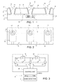
- an apparatus for nucleic acid sequencing is designated as a whole by the number 1 and comprises a body 2 housing a fluidic circuit 3, a base-detection device 4, and a conveying device 5, configured to control movement of nucleic acid strands in the fluidic circuit 3.
- the body 2 comprises a first, supporting, structural layer 7 and a second structural layer 8, arranged between which is a spacer layer 9 of nanometric thickness (for example, less than 20 nm).
- the first structural layer 7 may, for example, be a substrate of intrinsic semiconductor material, or else may be of polymeric material or some other non-conductive material.
- the first structural layer 7 could also be of a doped semiconductor material and be electrically insulated from the fluidic circuit 3, for example by a dielectric layer delimiting the fluidic circuit 3 itself.
- the second structural layer 8 and the spacer layer 9 may be, for example, respectively, of aluminium nitride (or else of intrinsic silicon or some other non-conductive or conductive material insulated from the fluidic circuit 3) and of silicon oxide.
- the fluidic circuit 3 is filled with a solution containing denatured strands of a nucleic acid and comprises a nanochannel 10, which, in one embodiment, is defined between the first structural layer 7 and the second structural layer 8. Denaturing may be obtained also directly in the fluidic circuit 3, upstream of the inlet of the nanochannel 10.
- the nanochannel 10 extends longitudinally along an axis A for a length of, for example, between 100 ⁇ m and 500 ⁇ m and has a cross-section, perpendicular to the axis A, of nanometric dimensions, in particular, less than 100 nm (for example 20 x 20 nm).
- the transverse dimensions of the nanochannel 10, in a direction perpendicular to its length, are selected for favouring passage of a single untangled and extended strand of nucleic acid, as in the case of the nanopores described in the articles cited above.
- the nanochannel 10 has a height and a width equal to the thickness of the spacer layer 9.
- the nanochannel 10 may have a different cross-section, for example rectangular, triangular, or circular.
- the fluidic circuit 3 comprises an inlet well 12, a control well 13, and a collection well 14, all defined by respective openings through the second structural layer 8.
- the nanochannel 10 is accessible from outside through the inlet well 12 to enable introduction of the solution to be analysed.
- the conveying device 5 (see also Figure 3 ) comprises: a first electrode 15, a second electrode 16, and a third electrode 17, which are arranged along the fluidic circuit 3 and are configured to apply respective voltages to a fluid present in the fluidic circuit 3; a first impedance-meter stage 18 and a second impedance-meter stage 19; and a control unit 20.
- the first electrode 15, the second electrode 16, and the third electrode 17 are arranged on a face of the second structural layer 8 opposite to the first structural layer 7 and coat the side walls, respectively, of the inlet well 12, of the control well 13, and of the collection well 14.
- the first electrode 15, the second electrode 16, and the third electrode 17 extend substantially as far as the nanochannel 10 for coming into contact with the solution loaded into the nanochannel 10 itself.
- the base-detection device 4 is located in a detection site along the nanochannel 10 in the proximity of the second electrode 16, so as to interact with an extended strand of nucleic acid, advancing in the nanochannel 10 in the detection site.
- the base-detection device 4 is configured to recognize individual bases or sequences of a programmed number of bases (for example four) in a portion of the strand that is advancing in the detection site.
- the raw sequence of the bases recognized by the base-detection device 4 is supplied to the control unit 20, which, if necessary, orders the raw sequence into an effective base sequence SEQ ( Figure 3 ) as explained in detail hereinafter, in order to take into account the detection modality and possible geometrical constraints of the base-detection device 4.
- the first impedance-meter stage 18 and the second impedance-meter stage 19 are connected for measuring, respectively, an electrical impedance Z' between the first electrode 15 and the second electrode 16 and an electrical impedance Z" between the second electrode 16 and the third electrode 17.
- the values of impedance Z', Z" measured are determined by the state of the nanochannel 10 and are supplied to the control unit 20. More precisely, the electrical impedance in a stretch of the nanochannel 10 containing the solution increases when a portion of a nucleic acid strand is present.
- the first impedance-meter stage 18 and the second impedance-meter stage 19 thus operate as presence sensors that detect the presence of a nucleic acid strand, respectively, in a first portion of the nanochannel 10, between the second electrode 16 and the first electrode 15, and in a second portion of the nanochannel 10, between the third electrode 17 and the second electrode 16.
- presence sensors of a different type may be used.
- the control unit 20 sets a first voltage V 1 on the first electrode 15, a second voltage V 2 on the second electrode 16, and a third voltage V 3 on the third electrode 17 as a function of the first impedance value Z' and of the second impedance value Z", respectively supplied by the first impedance-meter stage 18 and by the second impedance-meter stage 19.
- the voltages V 1 , V 2 , V 3 are each time selected on the basis of the impedance values Z', Z" so as to:
- the inlet well 12 is initially filled with a solution containing denatured nucleic acid strands, which have a negative electrical charge.
- the nanochannel 10 is occupied exclusively by the solution and is free from strands.
- the first electrical impedance Z' has a respective first (low) value.
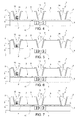
- the control unit 20 sets the first voltage V 1 to a negative value and the second voltage V 2 to a first positive value, so as to favour entry into the nanochannel 10 of one end of one of the nucleic acid strands present in the inlet well 12 ( Figure 5 ).
- the value of the third voltage V 3 in this step is indifferent and, for example, may be equal to the value of the second voltage V 2 .
- the first electrical impedance Z' detected by the first impedance-meter stage 18 starts to increase.
- the control unit 20 sets the first voltage V 1 to a positive value and increases the second voltage V 2 up to a respective second value, higher than the positive value of the first voltage V 1 .
- the positive value of the first voltage V 1 enables attraction of further denatured strands into the inlet well 12, for example from a loading reservoir not illustrated.
- the second voltage V 2 higher than the first voltage V 1 , produces an electrostatic force that attracts the end of the strand F present in the nanochannel 10 towards the second electrode 16 and the control well 13.
- the portion of the strand F still in the inlet well 12 unwraps as the end proceeds along the nanochannel 10.
- the control unit 20 sets the third voltage V 3 on the third electrode 17 to a value higher than the value of the second voltage V 2 on the second electrode 16 (which is thus intermediate between the first voltage V 1 and the third voltage V 3 ), for feeding the nucleic acid strand F along a second portion of the nanochannel 10, comprised between the control well 13, where the base-detection device 4 is located, and the collection well 14.
- the control unit 20 sets the values of the voltages V 1 , V 2 , V 3 so as to favour removal of any obstruction from the first portion of the nanochannel 10. In fact, even though introduction of a further nucleic acid strand into the nanochannel 10 already occupied is highly unlikely on account of the dimensions, an event of this type cannot be ruled out. In one embodiment, the control unit 20 thus applies forces that tend to remove an additional strand from the nanochannel 10 already occupied.
- control unit 20 sets the third voltage V 3 to a value higher than both the first voltage V 1 and the second voltage V 2 , and the first voltage V 1 to a value higher than the second voltage V 2 and thus intermediate between the second voltage V 2 and the third voltage V 3 .
- the strand F that has already reached the second portion of the nanochannel 10 is withheld, because the higher contribution of the third voltage V 3 prevails.
- Any possible strands further present in the first portion of the nanochannel 10 are instead expelled, because the electrostatic force determined by the first voltage V 1 and by the second voltage V 2 pushes the nucleic acids, which are negatively charged, towards the inlet well 12.
- the nanochannel 10 is thus freed from the presence of any possible additional strands.
- control unit 20 sets once again the voltages V 1 , V 2 , V 3 so as to control advance and stretching of the strand F present in the nanochannel 10.
- the difference between the third voltage V 3 and the first voltage V 1 determines the speed and direction of advance of the nucleic acid strand F along the nanochannel 10.
- the third voltage V 3 is higher than the first voltage V 1
- the strand F proceeds from the inlet well 12 towards the collection well 14.
- the third voltage V 3 is lower than the first voltage V 1
- the nucleic acid strand F moves in the opposite direction, from the collection well 14 to the inlet well 12.
- the absolute value of the difference between the third voltage V 3 and the first voltage V 1 determines the speed of advance of the strand F.
- the difference between the third voltage V 3 and the second voltage V 2 instead, causes stretching of the nucleic acid strand F that is advancing in the detection site.
- consecutive bases of a nucleic acid strand are arranged apart from one another with an approximately constant pitch (around 0.33 nm).
- the electrostatic force due to the difference between the third voltage V 3 and the second voltage V 2 acts upon the extended strand F and causes a separation between consecutive bases, in particular, at the detection site.
- the distance between consecutive bases may thus be controlled and adapted for optimizing the performance and reliability of the base-detection device 4.
- the base-detection device 4 is based upon hybridization of target oligonucleotides, it is possible to control the force on the strand F being examined for favouring hybridization and subsequently separate the strand F and the hybridized target oligonucleotide mechanically.
- the conveying device 5 thus enables an extremely fine and flexible control of the movement of the nucleic acid strands along the nanochannel 10.
- the use of the three electrodes 15, 16, 17 in fact enables control not only of the direction and speed of advance, but also of the force exerted on the portion of the strand F being examined in the base-detection device 4.
- the base-detection device 4 comprises a plurality of nanowire detectors 21 and a reading circuit 22, as is shown in Figure 8 .
- the nanowire detectors 21 are arranged in respective positions P1, P2, ... PK along the nanochannel 10 at the detection site.
- Each nanowire detector 21 defines a field-effect device and comprises a source region 23, a drain region 24, and a nanowire 25, which connects the source region 23 and the drain region 24.
- the source region 23 and the drain region 24 are of semiconductor material having a first type of conductivity, for example N+, and are opposite with respect to a region of passage of the nucleic acid strands that are advancing in the detection site, in particular, with respect to the axis A of the nanochannel 10.
- the semiconductor material may for example be silicon, germanium, InP, GaN.
- the nanowire 25 is of the same semiconductor material as that of the source region 23 and drain region 24, but has a second type of conductivity, for example P.
- the nanowire 25 defines a channel region between the source region 23 and the drain region 24.
- the conductance of the nanowire 25 is determined by the presence of electrical charge around the nanowire 25 itself. In particular, a negative charge in the vicinity of the nanowire 25 causes a drop of the conductivity with respect to a condition of neutral charge.
- the nanowires 25 of the nanowire detectors 21 are arranged in a direction transverse with respect to the axis A of the nanochannel 10 at the detection site so that a nucleic acid strand advancing along the nanochannel 10 itself will traverse the nanowires 25.
- the nanowires 25 are parallel to one another and are arranged in succession along the nanochannel 10.
- Each nanowire 25 is functionalized with respective nucleic acid probes 27.
- the nucleic acid probes 27 are defined by oligonucleotides with the same number N of bases, for example four.
- the nucleic acid probes 27 have the structure of a peptidonucleic acid (PNA), which contains repeated units of N-(2-aminoethyl)-glycine joined by peptide bonds and is electrically neutral.
- PNA peptidonucleic acid
- Associated to each nanowire 25 are nucleic acid probes 27 of the same type (i.e., containing the same base sequences). Given that the nucleic acid probes 27 are electrically neutral, their presence does not modify the state of conduction of the respective nanowire detector 21.
- the nucleic acid probes 27 may hybridize to corresponding base sequences in the nucleic acid strands advancing in the nanochannel 10. In this case, the sequence of the hybridized nucleic acid is withheld in the proximity of the corresponding nanowire 25 and with its own negative charge causes an increase of impedance of the nanowire detector 21.
- the nanowires 25 and the respective nucleic acid probes 27 exhaust the 4 N combinations that may be obtained with the number N of bases contained in each nucleic acid probe 27.
- the reading circuit 22 is configured to determine the state of conduction of each of the nanowire detectors 21, for example by impedance detection.
- the reading circuit 22 comprises an impedance-meter stage 30, for example including a voltage source 31 and a current sensor 32, and a multiplexer 33, configured to connect the impedance-meter stage 30 selectively to one of the nanowire detectors 21, in particular, to the drain region 24 (the source regions 23 of the nanowire detectors 21 are connected to a reference-potential line 34, for example a ground line).
- the nucleic acid probes 27 of one of the nanowire detectors 21 hybridize a corresponding sequence of the nucleic acid strand F advancing in the nanochannel 10, the negative charge of the strand F causes an increase of impedance of the nanowire 10, which is detected by the impedance-meter stage 30.
- the control unit 20 queries the base-detection device 4, which, in response to the queries, supplies information regarding the bases of the nucleic acid strand F advancing in the nanochannel 10.
- the control unit controls the multiplexer 33 by a control signal SC so as to connect the impedance-meter stage 30 in rotation to each of the nanowire detectors 21, and receives in response a read signal SR indicating the state of conduction of the nanowire detectors 21 connected to the impedance-meter stage 30 and, consequently, the presence of the respective set of bases in the portion of the nucleic acid strand F that is advancing in the detection site.
- an increase of impedance of one of the nanowire detectors 21 indicates the presence of a respective sequence of bases (four, in the example described) in the portion of the nucleic acid strand F that is advancing in the detection site, as illustrated in Figure 9 .
- the succession of the read signals SR defines the raw sequence supplied by the base-detection device 4.
- the control unit 20 reconstructs the effective base sequence SEQ that forms the nucleic acid strand F on the basis of the read signals SR received, taking into account the instants at which the read signals SR are generated and the positions P1, P2, ..., PK occupied by the respective nanowires 25 along the nanochannel 10.
- each sequence of bases recognized by the base-detection device 4 is translated, in the effective base sequence SEQ, by a number of positions such as to compensate the detection delay due to the distance between the generic position PJ of the hybridized nanowire detector 21, which has positively made a detection, and the position P1 of the first nanowire detector 21 reached by the nucleic acid strand F.
- the base-detection device 4 recognizes the sequence SB before the sequence SA ( Figures 10 and 11 : the impedance Z1 of the nanowire detector 21 corresponding to the sequence SA increases before the impedance ZJ of the nanowire detector 21 corresponding to the sequence SB).
- the control unit 20 re-aligns the sequences SA and SB and compensates the delay with a relative shift of J-1 positions of the sequence SB with respect to the sequence SA.
- Re-alignment may be obtained either by translating the sequence SB J-1 positions forwards or by translating the sequence SA J-1 positions backwards. More in general, re-alignment between a sequence detectable by the nanowire detector 21 in position PI and a sequence detectable by the nanowire detector 21 in position PJ (J > I) is obtained with a relative shift of J-I-1 positions in the effective base sequence SEQ. Translation in the effective base sequence SEQ of the raw sequence of the read signals SR may be obtained, for example, by entering the base sequences corresponding to the read signals SR into a shift register in positions translated with respect to a reference position as a function of the position of the nanowire detector 21.
- the control unit 20 may also take into account possible overlaps in the sequences recognized by the base-detection device 4. For instance, a sequence containing the bases AAAAC may be recognized both by the nanowire detector 21 associated to which are nucleic acid probes 27 with the sequence AAAA and by the nanowire detector 21 associated to which are nucleic acid probes 27 with the sequence AAAC.
- the overlapping portion in this case AAA may be used as check on the correctness of recognition.
- the conveying device 5 described with reference to Figures 1-7 enables control of the conditions in which the strand F interacts with the base-detection device 4.
- the conveying device enables determination both of the speed at which the strand F travels in the proximity of the nanowire detectors 21 and the force applied on the strand F itself. It is thus possible to control with high accuracy the hybridization conditions and the separation of the nucleic acid probes 27 and of the nucleic acid strand F in the nanochannel 10.
- the base-detection device may exploit a different operating principle.
- a base-detection device 104 of an optical type which comprises nucleic acid probes 127 fixed to a wall of the nanochannel 10 in respective detection positions P1', P2', ..., PK'.
- Fluorescent pigments are available in the solution present in the nanochannel and are incorporated in the nucleic acid probes 127 hybridized with corresponding sequences of the nucleic acid strand advancing in the nanochannel.
- the hybridized nucleic acid probes 127 are then selectively excited by light radiation at a first wavelength ⁇ 1, supplied by a light source 150, and emit in response light radiation at a second wavelength ⁇ 2.
- the radiation emitted by the nucleic acid probes 127 at the second wavelength ⁇ 2 is received by an image sensor 151.
- the images captured by the image sensor 151 are processed by a processing unit 152, which recognizes base sequences in the nucleic acid strand advancing in the nanochannel on the basis of the presence or to the absence of radiation at the second wavelength ⁇ 2 in the detection positions P1', P2', ..., PK'.
- the inspection of the nucleic acid probes may be carried out through the control well 13, which enables optical access to the nanochannel 10.
- a base-detection device 204 is of the cantilever type.
- the nucleic acid probes 227 are fixed to cantilever detection electrodes 221, the configuration of which changes when the respective nucleic acid probes 227 are bound to corresponding sequences of the strand advancing in the nanochannel.
- the charge associated to the strand F causes a deformation of the cantilever detection electrode 221, which may in turn alter the capacitance of a capacitor or bring about opening or closing of a circuit.
- the intermediate control well between the inlet well and the collection well may be absent.
- the control electrode MAY be integrated in the first structural layer or in the second structural layer.
Landscapes
- Chemical & Material Sciences (AREA)
- Health & Medical Sciences (AREA)
- Life Sciences & Earth Sciences (AREA)
- Engineering & Computer Science (AREA)
- Physics & Mathematics (AREA)
- Biomedical Technology (AREA)
- Analytical Chemistry (AREA)
- Organic Chemistry (AREA)
- Molecular Biology (AREA)
- General Health & Medical Sciences (AREA)
- Genetics & Genomics (AREA)
- Wood Science & Technology (AREA)
- Zoology (AREA)
- Biochemistry (AREA)
- Biotechnology (AREA)
- Bioinformatics & Cheminformatics (AREA)
- General Engineering & Computer Science (AREA)
- Biophysics (AREA)
- Proteomics, Peptides & Aminoacids (AREA)
- Immunology (AREA)
- Microbiology (AREA)
- General Physics & Mathematics (AREA)
- Hematology (AREA)
- Pathology (AREA)
- Chemical Kinetics & Catalysis (AREA)
- Dispersion Chemistry (AREA)
- Crystallography & Structural Chemistry (AREA)
- Plant Pathology (AREA)
- Spectroscopy & Molecular Physics (AREA)
- Medicinal Chemistry (AREA)
- Food Science & Technology (AREA)
- Urology & Nephrology (AREA)
- Nanotechnology (AREA)
- Fluid Mechanics (AREA)
- Clinical Laboratory Science (AREA)
- Electrochemistry (AREA)
- Investigating Or Analyzing Materials By The Use Of Electric Means (AREA)
- Apparatus Associated With Microorganisms And Enzymes (AREA)
Abstract
Description
- The present invention relates to an apparatus and to a method for nucleic acid sequencing based on nanochannels.
- Given the ever-increasing importance that nucleic acid sequencing is assuming, various techniques have been developed for determining the nucleotide sequence.
- Some of the known techniques are based upon the division of a nucleic acid molecule into short fragments, in general of some hundreds of bases, which are sequenced individually. The information collected on the individual portions is subsequently processed and aggregated for reconstructing the entire sequence of the bases that form the nucleic acid molecule. Reconstruction of the sequence is, however, an operation that is extremely complex and consuming in terms of resources, in particular, processing capacity, and time. Furthermore, it may happen that some fragments are not read and reconstructed correctly, and thus sequencing may be incomplete.
- The developments in the nanotechnology sector have contributed to develop new devices and techniques that enable handling of individual molecules, by exploiting, in particular, the electrical charge with which the nucleic acids are provided. For instance, in some devices appropriate electrical fields are used to cause passage of a single nucleic acid molecule through a nanopore in a membrane. In practice, the device has two chambers separated by a membrane, which has a nanopore and is provided with electrodes that enable creation of an electrical field. A solution containing molecules of a nucleic acid is loaded into one of the two chambers. Then, one end of a nucleic acid molecule, which normally presents as an entangled strand, may be introduced into the nanopore thanks to the electrical field. The dimensions of the nanopore are such that the presence of a portion of one molecule inhibits entry of ends of further molecules (the diameter of the nanopore may, for example, be between 5 nm and 10 nm). In this way, it is possible to isolate and handle a single sequence. The force exerted by the electrical field causes the strand forming the molecule to untangle and extend as it passes through the nanopore following after the end. The strand thus extended may be analysed for sequencing.
- Examples of devices of this type are described in Liu Q., Wu H., Wu L., Xie X., Kong J., et al. (2012), "Voltage-Driven Translocation of DNA through a High Throughput Conical Solid-State Nanopore", PLoS ONE 7(9): e46014; DOI:10.1371/journal.pone.0046014; and in Tsutsui, M. et al., "Transverse Electric Field Dragging of DNA in a Nanochannel" Sci. Rep. 2, 394; DOI:10.1038/srep00394 (2012).
- A limitation linked to the known devices lies in the low flexibility in controlling sliding of the strand through the nanopore and the forces exerted thereon. Since the accuracy in identifying the correct sequence of the bases depends markedly also upon these parameters, it is evident that fine control is decisive to obtain reliable results and efficient procedures of analysis.
- The aim of the present invention is to provide an apparatus and a method for nucleic acid sequencing that will enable the limitations described to be overcome.
- According to the present invention an apparatus and a method for nucleic acid sequencing based on nanochannels are provided as defined in
claims - For a better understanding of the invention, some embodiments thereof will now be described, purely by way of non-limiting example and with reference to the attached drawings, wherein:
-
Figure 1 is a cross-section through a body integrating a portion of an apparatus for nucleic acid sequencing according to an embodiment of the present invention; -
Figure 2 is a top plan view of the body ofFigure 1 ; -
Figure 3 is a block diagram of the apparatus ofFigure 1 ; -
Figures 4-7 show the cross-section ofFigure 1 in respective operating configurations; -
Figure 8 is a more detailed block diagram of a portion of the apparatus ofFigure 1 ; -
Figures 9-11 are graphs that show electrical quantities regarding the apparatus ofFigure 1 ; -
Figure 12 is a cross-section through a body integrating a portion of an apparatus for nucleic acid sequencing according to a different embodiment of the present invention; -
Figure 13 is a cross-section through a body integrating a portion of an apparatus for nucleic acid sequencing according to a further embodiment of the present invention; and -
Figure 14 shows an enlarged detail of the apparatus ofFigure 13 . - With reference to
Figures 1 and 2 , an apparatus for nucleic acid sequencing is designated as a whole by thenumber 1 and comprises abody 2 housing afluidic circuit 3, a base-detection device 4, and aconveying device 5, configured to control movement of nucleic acid strands in thefluidic circuit 3. - In one embodiment, the
body 2 comprises a first, supporting,structural layer 7 and a secondstructural layer 8, arranged between which is aspacer layer 9 of nanometric thickness (for example, less than 20 nm). The firststructural layer 7 may, for example, be a substrate of intrinsic semiconductor material, or else may be of polymeric material or some other non-conductive material. Alternatively, the firststructural layer 7 could also be of a doped semiconductor material and be electrically insulated from thefluidic circuit 3, for example by a dielectric layer delimiting thefluidic circuit 3 itself. The secondstructural layer 8 and thespacer layer 9 may be, for example, respectively, of aluminium nitride (or else of intrinsic silicon or some other non-conductive or conductive material insulated from the fluidic circuit 3) and of silicon oxide. - In use, the
fluidic circuit 3 is filled with a solution containing denatured strands of a nucleic acid and comprises ananochannel 10, which, in one embodiment, is defined between the firststructural layer 7 and the secondstructural layer 8. Denaturing may be obtained also directly in thefluidic circuit 3, upstream of the inlet of thenanochannel 10. Thenanochannel 10 extends longitudinally along an axis A for a length of, for example, between 100 µm and 500 µm and has a cross-section, perpendicular to the axis A, of nanometric dimensions, in particular, less than 100 nm (for example 20 x 20 nm). Specifically, the transverse dimensions of thenanochannel 10, in a direction perpendicular to its length, are selected for favouring passage of a single untangled and extended strand of nucleic acid, as in the case of the nanopores described in the articles cited above. In the example described herein, thenanochannel 10 has a height and a width equal to the thickness of thespacer layer 9. In other embodiments not shown, however, thenanochannel 10 may have a different cross-section, for example rectangular, triangular, or circular. - The
fluidic circuit 3 comprises an inlet well 12, a control well 13, and a collection well 14, all defined by respective openings through the secondstructural layer 8. In particular, thenanochannel 10 is accessible from outside through the inlet well 12 to enable introduction of the solution to be analysed. - Techniques for providing nanometric fluidic structures, in particular, nanochannels, are known, for example from the published patent application No.
US 2013/0213815 A1 . - The conveying device 5 (see also
Figure 3 ) comprises: afirst electrode 15, asecond electrode 16, and athird electrode 17, which are arranged along thefluidic circuit 3 and are configured to apply respective voltages to a fluid present in thefluidic circuit 3; a first impedance-meter stage 18 and a second impedance-meter stage 19; and acontrol unit 20. - In one embodiment, the
first electrode 15, thesecond electrode 16, and thethird electrode 17 are arranged on a face of the secondstructural layer 8 opposite to the firststructural layer 7 and coat the side walls, respectively, of the inlet well 12, of the control well 13, and of the collection well 14. In particular, thefirst electrode 15, thesecond electrode 16, and thethird electrode 17 extend substantially as far as thenanochannel 10 for coming into contact with the solution loaded into thenanochannel 10 itself. - The base-
detection device 4 is located in a detection site along thenanochannel 10 in the proximity of thesecond electrode 16, so as to interact with an extended strand of nucleic acid, advancing in thenanochannel 10 in the detection site. The base-detection device 4 is configured to recognize individual bases or sequences of a programmed number of bases (for example four) in a portion of the strand that is advancing in the detection site. The raw sequence of the bases recognized by the base-detection device 4 is supplied to thecontrol unit 20, which, if necessary, orders the raw sequence into an effective base sequence SEQ (Figure 3 ) as explained in detail hereinafter, in order to take into account the detection modality and possible geometrical constraints of the base-detection device 4. - The first impedance-
meter stage 18 and the second impedance-meter stage 19 are connected for measuring, respectively, an electrical impedance Z' between thefirst electrode 15 and thesecond electrode 16 and an electrical impedance Z" between thesecond electrode 16 and thethird electrode 17. The values of impedance Z', Z" measured are determined by the state of thenanochannel 10 and are supplied to thecontrol unit 20. More precisely, the electrical impedance in a stretch of thenanochannel 10 containing the solution increases when a portion of a nucleic acid strand is present. The first impedance-meter stage 18 and the second impedance-meter stage 19 thus operate as presence sensors that detect the presence of a nucleic acid strand, respectively, in a first portion of thenanochannel 10, between thesecond electrode 16 and thefirst electrode 15, and in a second portion of thenanochannel 10, between thethird electrode 17 and thesecond electrode 16. In other embodiments (not illustrated), presence sensors of a different type may be used. - The
control unit 20 sets a first voltage V1 on thefirst electrode 15, a second voltage V2 on thesecond electrode 16, and a third voltage V3 on thethird electrode 17 as a function of the first impedance value Z' and of the second impedance value Z", respectively supplied by the first impedance-meter stage 18 and by the second impedance-meter stage 19. - As described in what follows, the voltages V1, V2, V3 are each time selected on the basis of the impedance values Z', Z" so as to:
- favour introduction of one end of a nucleic acid strand F into the
nanochannel 10; - counter entry of further strands into the
nanochannel 10 when this is already occupied; - control the speed and direction of advance of the strand F present in the
nanochannel 10; and - apply to a portion of the strand F present in the nanochannel 10 a force such as to cause stretching of the strand F itself, i.e., a condition in which consecutive bases are arranged at a greater distance apart from one another than in the case of absence of external forces.
- As is shown in
Figure 4 , theinlet well 12 is initially filled with a solution containing denatured nucleic acid strands, which have a negative electrical charge. Thenanochannel 10 is occupied exclusively by the solution and is free from strands. The first electrical impedance Z' has a respective first (low) value. Thecontrol unit 20 sets the first voltage V1 to a negative value and the second voltage V2 to a first positive value, so as to favour entry into thenanochannel 10 of one end of one of the nucleic acid strands present in the inlet well 12 (Figure 5 ). The value of the third voltage V3 in this step is indifferent and, for example, may be equal to the value of the second voltage V2. - When the end of a nucleic acid strand F enters a first portion of the
nanochannel 10, comprised between the inlet well 12 and the control well 13, where the base-detection device 4 is located, the first electrical impedance Z' detected by the first impedance-meter stage 18 starts to increase. In response to the increase in the first electrical impedance Z', thecontrol unit 20 sets the first voltage V1 to a positive value and increases the second voltage V2 up to a respective second value, higher than the positive value of the first voltage V1. The positive value of the first voltage V1 enables attraction of further denatured strands into the inlet well 12, for example from a loading reservoir not illustrated. The second voltage V2, higher than the first voltage V1, produces an electrostatic force that attracts the end of the strand F present in thenanochannel 10 towards thesecond electrode 16 and the control well 13. The portion of the strand F still in the inlet well 12 unwraps as the end proceeds along thenanochannel 10. - When the end of the strand F present in the
nanochannel 10 reaches thesecond electrode 16 and the control well 13, thecontrol unit 20 sets the third voltage V3 on thethird electrode 17 to a value higher than the value of the second voltage V2 on the second electrode 16 (which is thus intermediate between the first voltage V1 and the third voltage V3), for feeding the nucleic acid strand F along a second portion of thenanochannel 10, comprised between the control well 13, where the base-detection device 4 is located, and the collection well 14. - Entry of the strand F into the second portion of the
nanochannel 10 causes an increase of the second electrical impedance Z", which is detected by the second impedance-meter stage 9. In response to the increase in the second electrical impedance Z", thecontrol unit 20 sets the values of the voltages V1, V2, V3 so as to favour removal of any obstruction from the first portion of thenanochannel 10. In fact, even though introduction of a further nucleic acid strand into thenanochannel 10 already occupied is highly unlikely on account of the dimensions, an event of this type cannot be ruled out. In one embodiment, thecontrol unit 20 thus applies forces that tend to remove an additional strand from thenanochannel 10 already occupied. In particular, thecontrol unit 20 sets the third voltage V3 to a value higher than both the first voltage V1 and the second voltage V2, and the first voltage V1 to a value higher than the second voltage V2 and thus intermediate between the second voltage V2 and the third voltage V3. In this way, the strand F that has already reached the second portion of thenanochannel 10 is withheld, because the higher contribution of the third voltage V3 prevails. Any possible strands further present in the first portion of thenanochannel 10 are instead expelled, because the electrostatic force determined by the first voltage V1 and by the second voltage V2 pushes the nucleic acids, which are negatively charged, towards the inlet well 12. Thenanochannel 10 is thus freed from the presence of any possible additional strands. - Once the procedure of removal of possible obstructions has been carried out, the
control unit 20 sets once again the voltages V1, V2, V3 so as to control advance and stretching of the strand F present in thenanochannel 10. - More precisely, the difference between the third voltage V3 and the first voltage V1 determines the speed and direction of advance of the nucleic acid strand F along the
nanochannel 10. When the third voltage V3 is higher than the first voltage V1, the strand F proceeds from the inlet well 12 towards the collection well 14. When, instead, the third voltage V3 is lower than the first voltage V1, the nucleic acid strand F moves in the opposite direction, from the collection well 14 to the inlet well 12. The absolute value of the difference between the third voltage V3 and the first voltage V1 determines the speed of advance of the strand F. - The difference between the third voltage V3 and the second voltage V2, instead, causes stretching of the nucleic acid strand F that is advancing in the detection site. In the absence of applied external forces, consecutive bases of a nucleic acid strand are arranged apart from one another with an approximately constant pitch (around 0.33 nm). The electrostatic force due to the difference between the third voltage V3 and the second voltage V2 acts upon the extended strand F and causes a separation between consecutive bases, in particular, at the detection site. The distance between consecutive bases may thus be controlled and adapted for optimizing the performance and reliability of the base-
detection device 4. Furthermore, if the base-detection device 4 is based upon hybridization of target oligonucleotides, it is possible to control the force on the strand F being examined for favouring hybridization and subsequently separate the strand F and the hybridized target oligonucleotide mechanically. - The conveying
device 5 thus enables an extremely fine and flexible control of the movement of the nucleic acid strands along thenanochannel 10. The use of the threeelectrodes detection device 4. - In one embodiment, the base-
detection device 4 comprises a plurality ofnanowire detectors 21 and areading circuit 22, as is shown inFigure 8 . Thenanowire detectors 21 are arranged in respective positions P1, P2, ... PK along thenanochannel 10 at the detection site. Eachnanowire detector 21 defines a field-effect device and comprises asource region 23, adrain region 24, and ananowire 25, which connects thesource region 23 and thedrain region 24. Thesource region 23 and thedrain region 24 are of semiconductor material having a first type of conductivity, for example N+, and are opposite with respect to a region of passage of the nucleic acid strands that are advancing in the detection site, in particular, with respect to the axis A of thenanochannel 10. The semiconductor material may for example be silicon, germanium, InP, GaN. Thenanowire 25 is of the same semiconductor material as that of thesource region 23 and drainregion 24, but has a second type of conductivity, for example P. Thenanowire 25 defines a channel region between thesource region 23 and thedrain region 24. The conductance of thenanowire 25 is determined by the presence of electrical charge around thenanowire 25 itself. In particular, a negative charge in the vicinity of thenanowire 25 causes a drop of the conductivity with respect to a condition of neutral charge. - The
nanowires 25 of thenanowire detectors 21 are arranged in a direction transverse with respect to the axis A of thenanochannel 10 at the detection site so that a nucleic acid strand advancing along thenanochannel 10 itself will traverse thenanowires 25. In one embodiment, thenanowires 25 are parallel to one another and are arranged in succession along thenanochannel 10. - Each
nanowire 25 is functionalized with respective nucleic acid probes 27. The nucleic acid probes 27 are defined by oligonucleotides with the same number N of bases, for example four. In one embodiment, the nucleic acid probes 27 have the structure of a peptidonucleic acid (PNA), which contains repeated units of N-(2-aminoethyl)-glycine joined by peptide bonds and is electrically neutral. Associated to eachnanowire 25 are nucleic acid probes 27 of the same type (i.e., containing the same base sequences). Given that the nucleic acid probes 27 are electrically neutral, their presence does not modify the state of conduction of therespective nanowire detector 21. However, the nucleic acid probes 27 may hybridize to corresponding base sequences in the nucleic acid strands advancing in thenanochannel 10. In this case, the sequence of the hybridized nucleic acid is withheld in the proximity of the correspondingnanowire 25 and with its own negative charge causes an increase of impedance of thenanowire detector 21. - The
nanowires 25 and the respective nucleic acid probes 27 exhaust the 4N combinations that may be obtained with the number N of bases contained in eachnucleic acid probe 27. In the example described, the possible combinations of four bases are 44 = 256 and there are present asmany nanowires 25, each with nucleic acid probes 27 of a respective type. Furthermore, eachnanowire 25 occupies a respective position P1, P2, ..., PK (where K = 4N is the number of possible combinations of bases) along thenanochannel 10. - The
reading circuit 22 is configured to determine the state of conduction of each of thenanowire detectors 21, for example by impedance detection. In one embodiment, thereading circuit 22 comprises an impedance-meter stage 30, for example including avoltage source 31 and acurrent sensor 32, and amultiplexer 33, configured to connect the impedance-meter stage 30 selectively to one of thenanowire detectors 21, in particular, to the drain region 24 (thesource regions 23 of thenanowire detectors 21 are connected to a reference-potential line 34, for example a ground line). - As has been mentioned, when the nucleic acid probes 27 of one of the
nanowire detectors 21 hybridize a corresponding sequence of the nucleic acid strand F advancing in thenanochannel 10, the negative charge of the strand F causes an increase of impedance of thenanowire 10, which is detected by the impedance-meter stage 30. - The
control unit 20 queries the base-detection device 4, which, in response to the queries, supplies information regarding the bases of the nucleic acid strand F advancing in thenanochannel 10. In detail, the control unit controls themultiplexer 33 by a control signal SC so as to connect the impedance-meter stage 30 in rotation to each of thenanowire detectors 21, and receives in response a read signal SR indicating the state of conduction of thenanowire detectors 21 connected to the impedance-meter stage 30 and, consequently, the presence of the respective set of bases in the portion of the nucleic acid strand F that is advancing in the detection site. More precisely, an increase of impedance of one of the nanowire detectors 21 (for example, in position PJ) indicates the presence of a respective sequence of bases (four, in the example described) in the portion of the nucleic acid strand F that is advancing in the detection site, as illustrated inFigure 9 . The succession of the read signals SR defines the raw sequence supplied by the base-detection device 4. - The
control unit 20 reconstructs the effective base sequence SEQ that forms the nucleic acid strand F on the basis of the read signals SR received, taking into account the instants at which the read signals SR are generated and the positions P1, P2, ..., PK occupied by therespective nanowires 25 along thenanochannel 10. In one embodiment, each sequence of bases recognized by the base-detection device 4 is translated, in the effective base sequence SEQ, by a number of positions such as to compensate the detection delay due to the distance between the generic position PJ of the hybridizednanowire detector 21, which has positively made a detection, and the position P1 of thefirst nanowire detector 21 reached by the nucleic acid strand F. For instance, if the nucleic acid strand F that is advancing in the detection site contains a sequence SA of N bases that may be detected by thenanowire detector 21 in position PJ, followed by a sequence SB of N bases that may be detected by thenanowire detector 21 in position P1, the base-detection device 4 recognizes the sequence SB before the sequence SA (Figures 10 and 11 : the impedance Z1 of thenanowire detector 21 corresponding to the sequence SA increases before the impedance ZJ of thenanowire detector 21 corresponding to the sequence SB). Thecontrol unit 20 re-aligns the sequences SA and SB and compensates the delay with a relative shift of J-1 positions of the sequence SB with respect to the sequence SA. Re-alignment may be obtained either by translating the sequence SB J-1 positions forwards or by translating the sequence SA J-1 positions backwards. More in general, re-alignment between a sequence detectable by thenanowire detector 21 in position PI and a sequence detectable by thenanowire detector 21 in position PJ (J > I) is obtained with a relative shift of J-I-1 positions in the effective base sequence SEQ. Translation in the effective base sequence SEQ of the raw sequence of the read signals SR may be obtained, for example, by entering the base sequences corresponding to the read signals SR into a shift register in positions translated with respect to a reference position as a function of the position of thenanowire detector 21. - The
control unit 20 may also take into account possible overlaps in the sequences recognized by the base-detection device 4. For instance, a sequence containing the bases AAAAC may be recognized both by thenanowire detector 21 associated to which are nucleic acid probes 27 with the sequence AAAA and by thenanowire detector 21 associated to which are nucleic acid probes 27 with the sequence AAAC. The overlapping portion (in this case AAA) may be used as check on the correctness of recognition. - The conveying
device 5 described with reference toFigures 1-7 enables control of the conditions in which the strand F interacts with the base-detection device 4. In particular, in the case of the base-detection device 4 based upon nanowire detectors, the conveying device enables determination both of the speed at which the strand F travels in the proximity of thenanowire detectors 21 and the force applied on the strand F itself. It is thus possible to control with high accuracy the hybridization conditions and the separation of the nucleic acid probes 27 and of the nucleic acid strand F in thenanochannel 10. - The base-detection device may exploit a different operating principle. For instance, in the embodiment of
Figure 12 , a base-detection device 104 of an optical type is used, which comprises nucleic acid probes 127 fixed to a wall of thenanochannel 10 in respective detection positions P1', P2', ..., PK'. Fluorescent pigments are available in the solution present in the nanochannel and are incorporated in the nucleic acid probes 127 hybridized with corresponding sequences of the nucleic acid strand advancing in the nanochannel. The hybridized nucleic acid probes 127 are then selectively excited by light radiation at a first wavelength λ1, supplied by alight source 150, and emit in response light radiation at a second wavelength λ2. The radiation emitted by the nucleic acid probes 127 at the second wavelength λ2 is received by animage sensor 151. The images captured by theimage sensor 151 are processed by aprocessing unit 152, which recognizes base sequences in the nucleic acid strand advancing in the nanochannel on the basis of the presence or to the absence of radiation at the second wavelength λ2 in the detection positions P1', P2', ..., PK'. The inspection of the nucleic acid probes may be carried out through the control well 13, which enables optical access to thenanochannel 10. - In a further embodiment, illustrated in
Figures 13 and 14 , a base-detection device 204 is of the cantilever type. In this case, the nucleic acid probes 227 are fixed tocantilever detection electrodes 221, the configuration of which changes when the respective nucleic acid probes 227 are bound to corresponding sequences of the strand advancing in the nanochannel. In particular, the charge associated to the strand F causes a deformation of thecantilever detection electrode 221, which may in turn alter the capacitance of a capacitor or bring about opening or closing of a circuit. - Finally, it is evident that modifications and variations may be made to the apparatus and to the method described, without thereby departing from the scope of the present invention, as defined in the annexed claims.
- For instance, in apparatuses that use a base-detection device not of an optical type, the intermediate control well between the inlet well and the collection well may be absent. In these cases, the control electrode MAY be integrated in the first structural layer or in the second structural layer.
Claims (20)
- An apparatus for nucleic acid sequencing, comprising:a nanochannel (10); anda conveying device (5), configured to move a nucleic acid strand (F) through the nanochannel (10);wherein the conveying device (5) comprises:a first electrode (15), a second electrode (16), and a third electrode (17) arranged along the nanochannel (10) so as to be in contact with a fluid occupying the nanochannel (10), the second electrode (16) being arranged between the first electrode (15) and the third electrode (17); anda control unit (20) configured to apply a first voltage (V1),a second voltage (V2), and a third voltage (V3) to the first electrode (15), the second electrode (16) and the third electrode (17), respectively, so as to control movement of the nucleic acid strand (F) through the nanochannel (10).
- An apparatus according to claim 1, comprising a first presence sensor (18) and a second presence sensor (19), configured to detect the presence of the nucleic acid strand (F), respectively, in a first portion of the nanochannel (10), between the first electrode (15) and the second electrode (16), and in a second portion of the nanochannel (10), between the second electrode (16) and the third electrode (17).
- An apparatus according to claim 2, wherein the first presence sensor (18) and the second presence sensor (19) comprise, respectively, a first impedance meter, configured to determine a first electrical impedance (Z') between the first electrode (15) and the second electrode (16), and a second impedance meter, configured to determine a second electrical impedance (Z") between the second electrode (16) and the third electrode (17).
- An apparatus according to claim 2 or claim 3, wherein the control unit (20) is configured to set the first voltage (V1), the second voltage (V2), and the third voltage (V3) on the basis of a response of the first presence sensor (18) and of the second presence sensor (19).
- An apparatus according to claim 4, wherein the control unit (20) is configured to set a negative value of the first voltage (V1) and a positive value of the second voltage (V2) when the first portion of the nanochannel (10) is free.
- An apparatus according to claim 4 or claim 5, wherein the control unit (20) is configured to set the the second voltage (V2) higher than the the first voltage (V1), when the first portion of the nanochannel (10) is occupied by the nucleic acid strand (F) and the second portion of the nanochannel (10) is free.
- An apparatus according to any one of claims 4 to 6, wherein the control unit (20) is configured to set the third voltage (V3) higher than the first voltage (V1), and the second voltage (V2) intermediate between the first voltage (V1) and the third voltage (V3), when the first portion of the nanochannel (10) and the second portion of the nanochannel (10) are occupied by the nucleic acid strand (F), in a first operating configuration.
- An apparatus according to claim 7, wherein the control unit (20) is configured to set the third voltage (V3) lower than the first voltage (V1), and the second voltage (V2) intermediate between the first voltage (V1) and the third voltage (V3), when the first portion of the nanochannel (10) and the second portion of the nanochannel (10) are occupied by the nucleic acid strand (F), in a second operating configuration.
- An apparatus according to claim 8, wherein the control unit (20) is configured to set the third voltage (V3) higher than the first voltage (V1), and the second voltage (V2) lower than the first voltage (V1), when the first portion of the nanochannel (10) and the second portion of the nanochannel (10) are occupied by the nucleic acid strand (F), in a third operating configuration.
- An apparatus according to any one of the preceding claims, comprising a base-detection device (4; 104; 204) set in a detection site and configured to detect bases of a portion of the nucleic acid strand (F) that is advancing in the detection site.
- An apparatus according to claim 10, wherein the base-detection device (4) comprises a plurality of field-effect detectors (21), each comprising a respective nanowire (25) and nucleic acid probes (27), which are defined by a sequence of bases and are fixed to the nanowire (25).
- An apparatus according to claim 11, wherein the nanowires (25) of the field-effect detectors (21) are parallel to one another and are arranged in succession along the nanochannel (10), associated to each nanowire (25) is a respective distinct type of nucleic acid probe (27) and all the nucleic acid probes (27) have a same number of bases.
- An apparatus according to any one of the preceding claims, wherein the nanochannel (10) has a length and transverse dimensions, in a direction perpendicular to the length, such as to enable entry of one end of a single nucleic acid strand (F) and prevent entry of further strands of nucleic acid when the nanochannel (10) is occupied.
- A method for nucleic acid sequencing, comprising:introducing one end of a nucleic acid strand (F) into a nanochannel (10) containing a solution; andcontrolling motion of the nucleic acid strand (F) along the nanochannel (10);wherein controlling motion of the nucleic acid strand (F) comprises applying a first voltage (V1), a second voltage (V2), and a third voltage (V3), respectively, to a first electrode (15), to a second electrode (16), and to a third electrode (17), arranged along the nanochannel (10) so as to be in contact with a fluid occupying the nanochannel (10), the second electrode (16) being arranged between the first electrode (15) and the third electrode (17).
- A method according to claim 14, comprising detecting the presence of the nucleic acid strand (F), respectively, in a first portion of the nanochannel (10), between the first electrode (15) and the second electrode (16), and in a second portion of the nanochannel (10), between the second electrode (16) and the third electrode (17).
- A method according to claim 14 or claim 15, wherein controlling motion of the nucleic acid strand (F) comprises setting a negative value of the first voltage (V1) and a positive value of the second voltage (V2) when the first portion of the nanochannel (10) is free.
- A method according to any one of claims 14 to 16, wherein controlling motion of the nucleic acid strand (F) comprises setting the second voltage (V2) higher than the first voltage (V1), when the first portion of the nanochannel (10) is occupied by the nucleic acid strand (F) and the second portion of the nanochannel (10) is free.
- A method according to any one of claims 14 to 17, wherein controlling motion of the nucleic acid strand (F) comprises setting the third voltage (V3) higher than the first voltage (V1), and the second voltage (V2) intermediate between the first voltage (V1) and the third voltage (V3), when the first portion of the nanochannel (10) and the second portion of the nanochannel (10) are occupied by the nucleic acid strand (F), in a first operating configuration.
- A method according to claim 18, wherein controlling motion of the nucleic acid strand (F) comprises setting the third voltage (V3) lower than the first voltage (V1), and the second voltage (V2) intermediate between the first voltage (V1) and the third voltage (V3), when the first portion of the nanochannel (10) and the second portion of the nanochannel (10) are occupied by the nucleic acid strand (F), in a second operating configuration.
- A method according to claim 19, wherein controlling motion of the nucleic acid strand (F) comprises setting the third voltage (V3) higher than the first voltage (V1), and the second voltage (V2) lower than the first voltage (V1), when the first portion of the nanochannel (10) and the second portion of the nanochannel (10) are occupied by the nucleic acid strand (F), in a third operating configuration.
Applications Claiming Priority (1)
| Application Number | Priority Date | Filing Date | Title |
|---|---|---|---|
| ITTO20140279 | 2014-04-03 |
Publications (2)
| Publication Number | Publication Date |
|---|---|
| EP2927329A1 true EP2927329A1 (en) | 2015-10-07 |
| EP2927329B1 EP2927329B1 (en) | 2019-06-19 |
Family
ID=50928173
Family Applications (1)
| Application Number | Title | Priority Date | Filing Date |
|---|---|---|---|
| EP15248047.1A Active EP2927329B1 (en) | 2014-04-03 | 2015-04-03 | Apparatus and method for nucleic acid sequencing based on nanochannels |
Country Status (3)
| Country | Link |
|---|---|
| US (1) | US9765326B2 (en) |
| EP (1) | EP2927329B1 (en) |
| CN (3) | CN104974930B (en) |
Families Citing this family (7)
| Publication number | Priority date | Publication date | Assignee | Title |
|---|---|---|---|---|
| US10190161B2 (en) * | 2014-04-03 | 2019-01-29 | Stmicroelectronics S.R.L. | Apparatus and method for nucleic acid sequencing based on nanowire detectors |
| US9765326B2 (en) * | 2014-04-03 | 2017-09-19 | Stmicroelectronics S.R.L. | Apparatus and method for nucleic acid sequencing based on nanochannels |
| CN109963949A (en) * | 2016-09-15 | 2019-07-02 | 豪夫迈·罗氏有限公司 | Nanopore-based sequencing using voltage mode with hybrid mode stimulation |
| US11213825B2 (en) * | 2017-05-16 | 2022-01-04 | Wisconsin Alumni Research Foundation | System and method for en masse patterning of molecule structures |
| CN114599796B (en) * | 2018-11-29 | 2025-03-07 | 通用测序技术公司 | Biopolymer Sequencing System |
| US20220113244A1 (en) * | 2019-02-12 | 2022-04-14 | Christoph Langhammer | System and method for detecting a presence of a particle in a fluid |
| CN111721709B (en) * | 2020-01-22 | 2021-08-17 | 中国科学院上海微系统与信息技术研究所 | A method and device for improving the signal-to-noise ratio of a silicon nanowire sensor using light modulation |
Citations (6)
| Publication number | Priority date | Publication date | Assignee | Title |
|---|---|---|---|---|
| EP1441213A1 (en) * | 2003-01-27 | 2004-07-28 | Agilent Technologies Inc. (a Delaware Corporation) | Apparatus and method for biopolymer identification during translocation through a nanopore |
| WO2010026488A2 (en) * | 2008-09-03 | 2010-03-11 | Quantumdx Group Limited | Methods and kits for nucleic acid sequencing |
| EP2311975A1 (en) * | 2009-10-13 | 2011-04-20 | Iee International Electronics & Engineering S.A. | Electrophoretic biomolecules separation device |
| WO2013012881A2 (en) * | 2011-07-20 | 2013-01-24 | The Regents Of The University Of California | Dual-pore device |
| US20130213815A1 (en) | 2012-02-16 | 2013-08-22 | Chao-Hung Steve Tung | Method of Fabricating a Nanochannel System for DNA Sequencing and Nanoparticle Characterization |
| WO2014059046A1 (en) * | 2012-10-10 | 2014-04-17 | Two Pore Guys, Inc. | Device for characterizing polymers |
Family Cites Families (19)
| Publication number | Priority date | Publication date | Assignee | Title |
|---|---|---|---|---|
| KR20030059187A (en) | 2000-10-10 | 2003-07-07 | 바이오포스 나노사이언스, 인크. | Nanoscale sensor |
| US20030215816A1 (en) | 2002-05-20 | 2003-11-20 | Narayan Sundararajan | Method for sequencing nucleic acids by observing the uptake of nucleotides modified with bulky groups |
| US20060073489A1 (en) | 2004-10-05 | 2006-04-06 | Gangqiang Li | Nanopore separation devices and methods of using same |
| CN101184853B (en) | 2005-03-29 | 2012-07-04 | 阿普尔拉股份有限公司 | Nanowire-Based System for Analysis of Nucleic Acids |
| TWI287041B (en) | 2005-04-27 | 2007-09-21 | Jung-Tang Huang | An ultra-rapid DNA sequencing method with nano-transistors array based devices |
| US20060275911A1 (en) | 2005-06-03 | 2006-12-07 | Shih-Yuan Wang | Method and apparatus for moleclular analysis using nanostructure-enhanced Raman spectroscopy |
| US9434990B2 (en) * | 2012-04-02 | 2016-09-06 | Lux Bio Group, Inc. | Apparatus and method for molecular separation, purification, and sensing |
| EP2639578B1 (en) | 2006-12-14 | 2016-09-14 | Life Technologies Corporation | Apparatus for measuring analytes using large scale fet arrays |
| US8003319B2 (en) | 2007-02-02 | 2011-08-23 | International Business Machines Corporation | Systems and methods for controlling position of charged polymer inside nanopore |
| US8262879B2 (en) * | 2008-09-03 | 2012-09-11 | Nabsys, Inc. | Devices and methods for determining the length of biopolymers and distances between probes bound thereto |
| US8882980B2 (en) | 2008-09-03 | 2014-11-11 | Nabsys, Inc. | Use of longitudinally displaced nanoscale electrodes for voltage sensing of biomolecules and other analytes in fluidic channels |
| DE102008042351A1 (en) | 2008-09-25 | 2010-04-01 | Robert Bosch Gmbh | Micromechanical sensor |
| US8673627B2 (en) | 2009-05-29 | 2014-03-18 | Life Technologies Corporation | Apparatus and methods for performing electrochemical reactions |
| US8969090B2 (en) | 2010-01-04 | 2015-03-03 | Life Technologies Corporation | DNA sequencing methods and detectors and systems for carrying out the same |
| US20120264617A1 (en) | 2011-04-14 | 2012-10-18 | Pettit John W | Dna sequencing employing nanomaterials |
| GB201111237D0 (en) | 2011-06-30 | 2011-08-17 | Isis Innovation | Nanochip |
| JP5670278B2 (en) * | 2011-08-09 | 2015-02-18 | 株式会社日立ハイテクノロジーズ | Nanopore analyzer |
| CN103275867B (en) | 2013-05-02 | 2014-06-04 | 华中科技大学 | Detection and acquisition system for solid-state nano-pore nucleic acid sequencing electric signals |
| US9765326B2 (en) * | 2014-04-03 | 2017-09-19 | Stmicroelectronics S.R.L. | Apparatus and method for nucleic acid sequencing based on nanochannels |
-
2015
- 2015-04-01 US US14/676,626 patent/US9765326B2/en not_active Expired - Fee Related
- 2015-04-03 CN CN201510159126.8A patent/CN104974930B/en not_active Expired - Fee Related
- 2015-04-03 CN CN201520201789.7U patent/CN204676081U/en not_active Withdrawn - After Issue
- 2015-04-03 CN CN201811506772.7A patent/CN110055168B/en not_active Expired - Fee Related
- 2015-04-03 EP EP15248047.1A patent/EP2927329B1/en active Active
Patent Citations (6)
| Publication number | Priority date | Publication date | Assignee | Title |
|---|---|---|---|---|
| EP1441213A1 (en) * | 2003-01-27 | 2004-07-28 | Agilent Technologies Inc. (a Delaware Corporation) | Apparatus and method for biopolymer identification during translocation through a nanopore |
| WO2010026488A2 (en) * | 2008-09-03 | 2010-03-11 | Quantumdx Group Limited | Methods and kits for nucleic acid sequencing |
| EP2311975A1 (en) * | 2009-10-13 | 2011-04-20 | Iee International Electronics & Engineering S.A. | Electrophoretic biomolecules separation device |
| WO2013012881A2 (en) * | 2011-07-20 | 2013-01-24 | The Regents Of The University Of California | Dual-pore device |
| US20130213815A1 (en) | 2012-02-16 | 2013-08-22 | Chao-Hung Steve Tung | Method of Fabricating a Nanochannel System for DNA Sequencing and Nanoparticle Characterization |
| WO2014059046A1 (en) * | 2012-10-10 | 2014-04-17 | Two Pore Guys, Inc. | Device for characterizing polymers |
Non-Patent Citations (2)
| Title |
|---|
| LIU Q.; WU H.; WU L.; XIE X.; KONG J. ET AL.: "Voltage-Driven Translocation of DNA through a High Throughput Conical Solid-State Nanopore", PLOS ONE, vol. 7, no. 9, 2012, pages E46014 |
| TSUTSUI, M. ET AL.: "Transverse Electric Field Dragging of DNA in a Nanochannel", SCI. REP., vol. 2, 2012, pages 394 |
Also Published As
| Publication number | Publication date |
|---|---|
| CN110055168B (en) | 2023-02-17 |
| US9765326B2 (en) | 2017-09-19 |
| EP2927329B1 (en) | 2019-06-19 |
| CN104974930B (en) | 2019-01-08 |
| CN104974930A (en) | 2015-10-14 |
| US20150284707A1 (en) | 2015-10-08 |
| CN204676081U (en) | 2015-09-30 |
| CN110055168A (en) | 2019-07-26 |
Similar Documents
| Publication | Publication Date | Title |
|---|---|---|
| EP2927330B1 (en) | Apparatus and method for nucleic acid sequencing based on nanowire detectors | |
| EP2927329B1 (en) | Apparatus and method for nucleic acid sequencing based on nanochannels | |
| EP2109685B1 (en) | Systems and methods for polymer characterization | |
| JP6274455B2 (en) | Methods and systems for manipulating molecules | |
| US20190071720A1 (en) | Devices, systems and methods for nucleic acid sequencing | |
| US11977069B2 (en) | Nanopore sensor, structure and device including the sensor, and methods of forming and using same | |
| US20170144158A1 (en) | Devices, systems and methods for linearization of polymers | |
| US9188560B2 (en) | Electro-diffusion enhanced bio-molecule charge detection using electrostatic interaction | |
| KR20160130380A (en) | Devices, systems and methods for sequencing biomolecules | |
| US9250202B2 (en) | Nanopore molecule detection system and molecule detection method based on potential measurement of insulated conductive thin layer | |
| US20150316529A1 (en) | System and method for real-time analysis of molecular sequences using nanochannels | |
| JP7084667B2 (en) | Microelectrode biosensor using dielectrophoresis and biological substance detection method using this | |
| US11648558B2 (en) | Biosensor apparatus, method of fabricating biosensor apparatus, biosensor chip, and method of detecting target molecule | |
| US20210139974A1 (en) | Method and apparatus for the analysis and identification of molecules | |
| WO2019036640A1 (en) | High density resonant tunneling | |
| KR102012638B1 (en) | Method and mobile apparatus for detecting bio-marker for alzheimer's disease | |
| AU2023202006B1 (en) | System, Apparatus and Process | |
| JP5029674B2 (en) | Analyte determination device and analyte determination method | |
| WO2025193633A1 (en) | Devices, systems, and methods for analyzing biomolecules | |
| US10948455B2 (en) | Sequencer |
Legal Events
| Date | Code | Title | Description |
|---|---|---|---|
| PUAI | Public reference made under article 153(3) epc to a published international application that has entered the european phase |
Free format text: ORIGINAL CODE: 0009012 |
|
| AK | Designated contracting states |
Kind code of ref document: A1 Designated state(s): AL AT BE BG CH CY CZ DE DK EE ES FI FR GB GR HR HU IE IS IT LI LT LU LV MC MK MT NL NO PL PT RO RS SE SI SK SM TR |
|
| AX | Request for extension of the european patent |
Extension state: BA ME |
|
| 17P | Request for examination filed |
Effective date: 20160407 |
|
| RBV | Designated contracting states (corrected) |
Designated state(s): AL AT BE BG CH CY CZ DE DK EE ES FI FR GB GR HR HU IE IS IT LI LT LU LV MC MK MT NL NO PL PT RO RS SE SI SK SM TR |
|
| STAA | Information on the status of an ep patent application or granted ep patent |
Free format text: STATUS: EXAMINATION IS IN PROGRESS |
|
| 17Q | First examination report despatched |
Effective date: 20170424 |
|
| GRAP | Despatch of communication of intention to grant a patent |
Free format text: ORIGINAL CODE: EPIDOSNIGR1 |
|
| STAA | Information on the status of an ep patent application or granted ep patent |
Free format text: STATUS: GRANT OF PATENT IS INTENDED |
|
| INTG | Intention to grant announced |
Effective date: 20180727 |
|
| GRAJ | Information related to disapproval of communication of intention to grant by the applicant or resumption of examination proceedings by the epo deleted |
Free format text: ORIGINAL CODE: EPIDOSDIGR1 |
|
| STAA | Information on the status of an ep patent application or granted ep patent |
Free format text: STATUS: EXAMINATION IS IN PROGRESS |
|
| GRAP | Despatch of communication of intention to grant a patent |
Free format text: ORIGINAL CODE: EPIDOSNIGR1 |
|
| STAA | Information on the status of an ep patent application or granted ep patent |
Free format text: STATUS: GRANT OF PATENT IS INTENDED |
|
| INTC | Intention to grant announced (deleted) | ||
| INTG | Intention to grant announced |
Effective date: 20190109 |
|
| GRAS | Grant fee paid |
Free format text: ORIGINAL CODE: EPIDOSNIGR3 |
|
| GRAA | (expected) grant |
Free format text: ORIGINAL CODE: 0009210 |
|
| STAA | Information on the status of an ep patent application or granted ep patent |
Free format text: STATUS: THE PATENT HAS BEEN GRANTED |
|
| AK | Designated contracting states |
Kind code of ref document: B1 Designated state(s): AL AT BE BG CH CY CZ DE DK EE ES FI FR GB GR HR HU IE IS IT LI LT LU LV MC MK MT NL NO PL PT RO RS SE SI SK SM TR |
|
| REG | Reference to a national code |
Ref country code: GB Ref legal event code: FG4D |
|
| REG | Reference to a national code |
Ref country code: CH Ref legal event code: EP |
|
| REG | Reference to a national code |
Ref country code: IE Ref legal event code: FG4D |
|
| REG | Reference to a national code |
Ref country code: AT Ref legal event code: REF Ref document number: 1145576 Country of ref document: AT Kind code of ref document: T Effective date: 20190715 |
|
| REG | Reference to a national code |
Ref country code: DE Ref legal event code: R096 Ref document number: 602015032178 Country of ref document: DE |
|
| REG | Reference to a national code |
Ref country code: NL Ref legal event code: MP Effective date: 20190619 |
|
| PG25 | Lapsed in a contracting state [announced via postgrant information from national office to epo] |
Ref country code: LT Free format text: LAPSE BECAUSE OF FAILURE TO SUBMIT A TRANSLATION OF THE DESCRIPTION OR TO PAY THE FEE WITHIN THE PRESCRIBED TIME-LIMIT Effective date: 20190619 Ref country code: HR Free format text: LAPSE BECAUSE OF FAILURE TO SUBMIT A TRANSLATION OF THE DESCRIPTION OR TO PAY THE FEE WITHIN THE PRESCRIBED TIME-LIMIT Effective date: 20190619 Ref country code: NO Free format text: LAPSE BECAUSE OF FAILURE TO SUBMIT A TRANSLATION OF THE DESCRIPTION OR TO PAY THE FEE WITHIN THE PRESCRIBED TIME-LIMIT Effective date: 20190919 Ref country code: SE Free format text: LAPSE BECAUSE OF FAILURE TO SUBMIT A TRANSLATION OF THE DESCRIPTION OR TO PAY THE FEE WITHIN THE PRESCRIBED TIME-LIMIT Effective date: 20190619 Ref country code: AL Free format text: LAPSE BECAUSE OF FAILURE TO SUBMIT A TRANSLATION OF THE DESCRIPTION OR TO PAY THE FEE WITHIN THE PRESCRIBED TIME-LIMIT Effective date: 20190619 Ref country code: FI Free format text: LAPSE BECAUSE OF FAILURE TO SUBMIT A TRANSLATION OF THE DESCRIPTION OR TO PAY THE FEE WITHIN THE PRESCRIBED TIME-LIMIT Effective date: 20190619 |
|
| REG | Reference to a national code |
Ref country code: LT Ref legal event code: MG4D |
|
| PG25 | Lapsed in a contracting state [announced via postgrant information from national office to epo] |
Ref country code: BG Free format text: LAPSE BECAUSE OF FAILURE TO SUBMIT A TRANSLATION OF THE DESCRIPTION OR TO PAY THE FEE WITHIN THE PRESCRIBED TIME-LIMIT Effective date: 20190919 Ref country code: LV Free format text: LAPSE BECAUSE OF FAILURE TO SUBMIT A TRANSLATION OF THE DESCRIPTION OR TO PAY THE FEE WITHIN THE PRESCRIBED TIME-LIMIT Effective date: 20190619 Ref country code: RS Free format text: LAPSE BECAUSE OF FAILURE TO SUBMIT A TRANSLATION OF THE DESCRIPTION OR TO PAY THE FEE WITHIN THE PRESCRIBED TIME-LIMIT Effective date: 20190619 Ref country code: GR Free format text: LAPSE BECAUSE OF FAILURE TO SUBMIT A TRANSLATION OF THE DESCRIPTION OR TO PAY THE FEE WITHIN THE PRESCRIBED TIME-LIMIT Effective date: 20190920 |
|
| REG | Reference to a national code |
Ref country code: AT Ref legal event code: MK05 Ref document number: 1145576 Country of ref document: AT Kind code of ref document: T Effective date: 20190619 |
|
| PG25 | Lapsed in a contracting state [announced via postgrant information from national office to epo] |
Ref country code: EE Free format text: LAPSE BECAUSE OF FAILURE TO SUBMIT A TRANSLATION OF THE DESCRIPTION OR TO PAY THE FEE WITHIN THE PRESCRIBED TIME-LIMIT Effective date: 20190619 Ref country code: PT Free format text: LAPSE BECAUSE OF FAILURE TO SUBMIT A TRANSLATION OF THE DESCRIPTION OR TO PAY THE FEE WITHIN THE PRESCRIBED TIME-LIMIT Effective date: 20191021 Ref country code: SK Free format text: LAPSE BECAUSE OF FAILURE TO SUBMIT A TRANSLATION OF THE DESCRIPTION OR TO PAY THE FEE WITHIN THE PRESCRIBED TIME-LIMIT Effective date: 20190619 Ref country code: RO Free format text: LAPSE BECAUSE OF FAILURE TO SUBMIT A TRANSLATION OF THE DESCRIPTION OR TO PAY THE FEE WITHIN THE PRESCRIBED TIME-LIMIT Effective date: 20190619 Ref country code: AT Free format text: LAPSE BECAUSE OF FAILURE TO SUBMIT A TRANSLATION OF THE DESCRIPTION OR TO PAY THE FEE WITHIN THE PRESCRIBED TIME-LIMIT Effective date: 20190619 Ref country code: NL Free format text: LAPSE BECAUSE OF FAILURE TO SUBMIT A TRANSLATION OF THE DESCRIPTION OR TO PAY THE FEE WITHIN THE PRESCRIBED TIME-LIMIT Effective date: 20190619 Ref country code: CZ Free format text: LAPSE BECAUSE OF FAILURE TO SUBMIT A TRANSLATION OF THE DESCRIPTION OR TO PAY THE FEE WITHIN THE PRESCRIBED TIME-LIMIT Effective date: 20190619 |
|
| PG25 | Lapsed in a contracting state [announced via postgrant information from national office to epo] |
Ref country code: SM Free format text: LAPSE BECAUSE OF FAILURE TO SUBMIT A TRANSLATION OF THE DESCRIPTION OR TO PAY THE FEE WITHIN THE PRESCRIBED TIME-LIMIT Effective date: 20190619 Ref country code: ES Free format text: LAPSE BECAUSE OF FAILURE TO SUBMIT A TRANSLATION OF THE DESCRIPTION OR TO PAY THE FEE WITHIN THE PRESCRIBED TIME-LIMIT Effective date: 20190619 Ref country code: IT Free format text: LAPSE BECAUSE OF FAILURE TO SUBMIT A TRANSLATION OF THE DESCRIPTION OR TO PAY THE FEE WITHIN THE PRESCRIBED TIME-LIMIT Effective date: 20190619 Ref country code: IS Free format text: LAPSE BECAUSE OF FAILURE TO SUBMIT A TRANSLATION OF THE DESCRIPTION OR TO PAY THE FEE WITHIN THE PRESCRIBED TIME-LIMIT Effective date: 20191019 |
|
| PG25 | Lapsed in a contracting state [announced via postgrant information from national office to epo] |
Ref country code: TR Free format text: LAPSE BECAUSE OF FAILURE TO SUBMIT A TRANSLATION OF THE DESCRIPTION OR TO PAY THE FEE WITHIN THE PRESCRIBED TIME-LIMIT Effective date: 20190619 |
|
| PG25 | Lapsed in a contracting state [announced via postgrant information from national office to epo] |
Ref country code: DK Free format text: LAPSE BECAUSE OF FAILURE TO SUBMIT A TRANSLATION OF THE DESCRIPTION OR TO PAY THE FEE WITHIN THE PRESCRIBED TIME-LIMIT Effective date: 20190619 Ref country code: PL Free format text: LAPSE BECAUSE OF FAILURE TO SUBMIT A TRANSLATION OF THE DESCRIPTION OR TO PAY THE FEE WITHIN THE PRESCRIBED TIME-LIMIT Effective date: 20190619 |
|
| PG25 | Lapsed in a contracting state [announced via postgrant information from national office to epo] |
Ref country code: IS Free format text: LAPSE BECAUSE OF FAILURE TO SUBMIT A TRANSLATION OF THE DESCRIPTION OR TO PAY THE FEE WITHIN THE PRESCRIBED TIME-LIMIT Effective date: 20200224 |
|
| REG | Reference to a national code |
Ref country code: DE Ref legal event code: R097 Ref document number: 602015032178 Country of ref document: DE |
|
| PLBE | No opposition filed within time limit |
Free format text: ORIGINAL CODE: 0009261 |
|
| STAA | Information on the status of an ep patent application or granted ep patent |
Free format text: STATUS: NO OPPOSITION FILED WITHIN TIME LIMIT |
|
| PG2D | Information on lapse in contracting state deleted |
Ref country code: IS |
|
| 26N | No opposition filed |
Effective date: 20200603 |
|
| PG25 | Lapsed in a contracting state [announced via postgrant information from national office to epo] |
Ref country code: SI Free format text: LAPSE BECAUSE OF FAILURE TO SUBMIT A TRANSLATION OF THE DESCRIPTION OR TO PAY THE FEE WITHIN THE PRESCRIBED TIME-LIMIT Effective date: 20190619 |
|
| PG25 | Lapsed in a contracting state [announced via postgrant information from national office to epo] |
Ref country code: MC Free format text: LAPSE BECAUSE OF FAILURE TO SUBMIT A TRANSLATION OF THE DESCRIPTION OR TO PAY THE FEE WITHIN THE PRESCRIBED TIME-LIMIT Effective date: 20190619 |
|
| REG | Reference to a national code |
Ref country code: CH Ref legal event code: PL |
|
| PG25 | Lapsed in a contracting state [announced via postgrant information from national office to epo] |
Ref country code: CH Free format text: LAPSE BECAUSE OF NON-PAYMENT OF DUE FEES Effective date: 20200430 Ref country code: LU Free format text: LAPSE BECAUSE OF NON-PAYMENT OF DUE FEES Effective date: 20200403 Ref country code: LI Free format text: LAPSE BECAUSE OF NON-PAYMENT OF DUE FEES Effective date: 20200430 Ref country code: FR Free format text: LAPSE BECAUSE OF NON-PAYMENT OF DUE FEES Effective date: 20200430 |
|
| REG | Reference to a national code |
Ref country code: BE Ref legal event code: MM Effective date: 20200430 |
|
| PG25 | Lapsed in a contracting state [announced via postgrant information from national office to epo] |
Ref country code: BE Free format text: LAPSE BECAUSE OF NON-PAYMENT OF DUE FEES Effective date: 20200430 |
|
| GBPC | Gb: european patent ceased through non-payment of renewal fee |
Effective date: 20200403 |
|
| PG25 | Lapsed in a contracting state [announced via postgrant information from national office to epo] |
Ref country code: GB Free format text: LAPSE BECAUSE OF NON-PAYMENT OF DUE FEES Effective date: 20200403 Ref country code: IE Free format text: LAPSE BECAUSE OF NON-PAYMENT OF DUE FEES Effective date: 20200403 |
|
| PG25 | Lapsed in a contracting state [announced via postgrant information from national office to epo] |
Ref country code: MT Free format text: LAPSE BECAUSE OF FAILURE TO SUBMIT A TRANSLATION OF THE DESCRIPTION OR TO PAY THE FEE WITHIN THE PRESCRIBED TIME-LIMIT Effective date: 20190619 Ref country code: CY Free format text: LAPSE BECAUSE OF FAILURE TO SUBMIT A TRANSLATION OF THE DESCRIPTION OR TO PAY THE FEE WITHIN THE PRESCRIBED TIME-LIMIT Effective date: 20190619 |
|
| PG25 | Lapsed in a contracting state [announced via postgrant information from national office to epo] |
Ref country code: MK Free format text: LAPSE BECAUSE OF FAILURE TO SUBMIT A TRANSLATION OF THE DESCRIPTION OR TO PAY THE FEE WITHIN THE PRESCRIBED TIME-LIMIT Effective date: 20190619 |
|
| PGFP | Annual fee paid to national office [announced via postgrant information from national office to epo] |
Ref country code: DE Payment date: 20230321 Year of fee payment: 9 |
|
| REG | Reference to a national code |
Ref country code: DE Ref legal event code: R119 Ref document number: 602015032178 Country of ref document: DE |
|
| PG25 | Lapsed in a contracting state [announced via postgrant information from national office to epo] |
Ref country code: DE Free format text: LAPSE BECAUSE OF NON-PAYMENT OF DUE FEES Effective date: 20251104 |