EP2927037A1 - Power plant for vehicle - Google Patents
Power plant for vehicle Download PDFInfo
- Publication number
- EP2927037A1 EP2927037A1 EP13859429.6A EP13859429A EP2927037A1 EP 2927037 A1 EP2927037 A1 EP 2927037A1 EP 13859429 A EP13859429 A EP 13859429A EP 2927037 A1 EP2927037 A1 EP 2927037A1
- Authority
- EP
- European Patent Office
- Prior art keywords
- engine
- vehicle
- electric motor
- power plant
- vibration
- Prior art date
- Legal status (The legal status is an assumption and is not a legal conclusion. Google has not performed a legal analysis and makes no representation as to the accuracy of the status listed.)
- Withdrawn
Links
Images


Classifications
-
- B—PERFORMING OPERATIONS; TRANSPORTING
- B60—VEHICLES IN GENERAL
- B60K—ARRANGEMENT OR MOUNTING OF PROPULSION UNITS OR OF TRANSMISSIONS IN VEHICLES; ARRANGEMENT OR MOUNTING OF PLURAL DIVERSE PRIME-MOVERS IN VEHICLES; AUXILIARY DRIVES FOR VEHICLES; INSTRUMENTATION OR DASHBOARDS FOR VEHICLES; ARRANGEMENTS IN CONNECTION WITH COOLING, AIR INTAKE, GAS EXHAUST OR FUEL SUPPLY OF PROPULSION UNITS IN VEHICLES
- B60K6/00—Arrangement or mounting of plural diverse prime-movers for mutual or common propulsion, e.g. hybrid propulsion systems comprising electric motors and internal combustion engines
- B60K6/20—Arrangement or mounting of plural diverse prime-movers for mutual or common propulsion, e.g. hybrid propulsion systems comprising electric motors and internal combustion engines the prime-movers consisting of electric motors and internal combustion engines, e.g. HEVs
- B60K6/42—Arrangement or mounting of plural diverse prime-movers for mutual or common propulsion, e.g. hybrid propulsion systems comprising electric motors and internal combustion engines the prime-movers consisting of electric motors and internal combustion engines, e.g. HEVs characterised by the architecture of the hybrid electric vehicle
- B60K6/48—Parallel type
-
- B—PERFORMING OPERATIONS; TRANSPORTING
- B60—VEHICLES IN GENERAL
- B60K—ARRANGEMENT OR MOUNTING OF PROPULSION UNITS OR OF TRANSMISSIONS IN VEHICLES; ARRANGEMENT OR MOUNTING OF PLURAL DIVERSE PRIME-MOVERS IN VEHICLES; AUXILIARY DRIVES FOR VEHICLES; INSTRUMENTATION OR DASHBOARDS FOR VEHICLES; ARRANGEMENTS IN CONNECTION WITH COOLING, AIR INTAKE, GAS EXHAUST OR FUEL SUPPLY OF PROPULSION UNITS IN VEHICLES
- B60K1/00—Arrangement or mounting of electrical propulsion units
-
- B—PERFORMING OPERATIONS; TRANSPORTING
- B60—VEHICLES IN GENERAL
- B60K—ARRANGEMENT OR MOUNTING OF PROPULSION UNITS OR OF TRANSMISSIONS IN VEHICLES; ARRANGEMENT OR MOUNTING OF PLURAL DIVERSE PRIME-MOVERS IN VEHICLES; AUXILIARY DRIVES FOR VEHICLES; INSTRUMENTATION OR DASHBOARDS FOR VEHICLES; ARRANGEMENTS IN CONNECTION WITH COOLING, AIR INTAKE, GAS EXHAUST OR FUEL SUPPLY OF PROPULSION UNITS IN VEHICLES
- B60K17/00—Arrangement or mounting of transmissions in vehicles
- B60K17/04—Arrangement or mounting of transmissions in vehicles characterised by arrangement, location or kind of gearing
-
- B—PERFORMING OPERATIONS; TRANSPORTING
- B60—VEHICLES IN GENERAL
- B60K—ARRANGEMENT OR MOUNTING OF PROPULSION UNITS OR OF TRANSMISSIONS IN VEHICLES; ARRANGEMENT OR MOUNTING OF PLURAL DIVERSE PRIME-MOVERS IN VEHICLES; AUXILIARY DRIVES FOR VEHICLES; INSTRUMENTATION OR DASHBOARDS FOR VEHICLES; ARRANGEMENTS IN CONNECTION WITH COOLING, AIR INTAKE, GAS EXHAUST OR FUEL SUPPLY OF PROPULSION UNITS IN VEHICLES
- B60K5/00—Arrangement or mounting of internal-combustion or jet-propulsion units
- B60K5/04—Arrangement or mounting of internal-combustion or jet-propulsion units with the engine main axis, e.g. crankshaft axis, transversely to the longitudinal centre line of the vehicle
-
- B—PERFORMING OPERATIONS; TRANSPORTING
- B60—VEHICLES IN GENERAL
- B60K—ARRANGEMENT OR MOUNTING OF PROPULSION UNITS OR OF TRANSMISSIONS IN VEHICLES; ARRANGEMENT OR MOUNTING OF PLURAL DIVERSE PRIME-MOVERS IN VEHICLES; AUXILIARY DRIVES FOR VEHICLES; INSTRUMENTATION OR DASHBOARDS FOR VEHICLES; ARRANGEMENTS IN CONNECTION WITH COOLING, AIR INTAKE, GAS EXHAUST OR FUEL SUPPLY OF PROPULSION UNITS IN VEHICLES
- B60K5/00—Arrangement or mounting of internal-combustion or jet-propulsion units
- B60K5/12—Arrangement of engine supports
- B60K5/1208—Resilient supports
- B60K5/1216—Resilient supports characterised by the location of the supports relative to the motor or to each other
-
- B—PERFORMING OPERATIONS; TRANSPORTING
- B60—VEHICLES IN GENERAL
- B60K—ARRANGEMENT OR MOUNTING OF PROPULSION UNITS OR OF TRANSMISSIONS IN VEHICLES; ARRANGEMENT OR MOUNTING OF PLURAL DIVERSE PRIME-MOVERS IN VEHICLES; AUXILIARY DRIVES FOR VEHICLES; INSTRUMENTATION OR DASHBOARDS FOR VEHICLES; ARRANGEMENTS IN CONNECTION WITH COOLING, AIR INTAKE, GAS EXHAUST OR FUEL SUPPLY OF PROPULSION UNITS IN VEHICLES
- B60K6/00—Arrangement or mounting of plural diverse prime-movers for mutual or common propulsion, e.g. hybrid propulsion systems comprising electric motors and internal combustion engines
- B60K6/20—Arrangement or mounting of plural diverse prime-movers for mutual or common propulsion, e.g. hybrid propulsion systems comprising electric motors and internal combustion engines the prime-movers consisting of electric motors and internal combustion engines, e.g. HEVs
- B60K6/22—Arrangement or mounting of plural diverse prime-movers for mutual or common propulsion, e.g. hybrid propulsion systems comprising electric motors and internal combustion engines the prime-movers consisting of electric motors and internal combustion engines, e.g. HEVs characterised by apparatus, components or means specially adapted for HEVs
- B60K6/40—Arrangement or mounting of plural diverse prime-movers for mutual or common propulsion, e.g. hybrid propulsion systems comprising electric motors and internal combustion engines the prime-movers consisting of electric motors and internal combustion engines, e.g. HEVs characterised by apparatus, components or means specially adapted for HEVs characterised by the assembly or relative disposition of components
-
- B—PERFORMING OPERATIONS; TRANSPORTING
- B60—VEHICLES IN GENERAL
- B60K—ARRANGEMENT OR MOUNTING OF PROPULSION UNITS OR OF TRANSMISSIONS IN VEHICLES; ARRANGEMENT OR MOUNTING OF PLURAL DIVERSE PRIME-MOVERS IN VEHICLES; AUXILIARY DRIVES FOR VEHICLES; INSTRUMENTATION OR DASHBOARDS FOR VEHICLES; ARRANGEMENTS IN CONNECTION WITH COOLING, AIR INTAKE, GAS EXHAUST OR FUEL SUPPLY OF PROPULSION UNITS IN VEHICLES
- B60K6/00—Arrangement or mounting of plural diverse prime-movers for mutual or common propulsion, e.g. hybrid propulsion systems comprising electric motors and internal combustion engines
- B60K6/20—Arrangement or mounting of plural diverse prime-movers for mutual or common propulsion, e.g. hybrid propulsion systems comprising electric motors and internal combustion engines the prime-movers consisting of electric motors and internal combustion engines, e.g. HEVs
- B60K6/50—Architecture of the driveline characterised by arrangement or kind of transmission units
- B60K6/54—Transmission for changing ratio
- B60K6/543—Transmission for changing ratio the transmission being a continuously variable transmission
-
- F—MECHANICAL ENGINEERING; LIGHTING; HEATING; WEAPONS; BLASTING
- F02—COMBUSTION ENGINES; HOT-GAS OR COMBUSTION-PRODUCT ENGINE PLANTS
- F02D—CONTROLLING COMBUSTION ENGINES
- F02D29/00—Controlling engines, such controlling being peculiar to the devices driven thereby, the devices being other than parts or accessories essential to engine operation, e.g. controlling of engines by signals external thereto
- F02D29/02—Controlling engines, such controlling being peculiar to the devices driven thereby, the devices being other than parts or accessories essential to engine operation, e.g. controlling of engines by signals external thereto peculiar to engines driving vehicles; peculiar to engines driving variable pitch propellers
-
- B—PERFORMING OPERATIONS; TRANSPORTING
- B60—VEHICLES IN GENERAL
- B60K—ARRANGEMENT OR MOUNTING OF PROPULSION UNITS OR OF TRANSMISSIONS IN VEHICLES; ARRANGEMENT OR MOUNTING OF PLURAL DIVERSE PRIME-MOVERS IN VEHICLES; AUXILIARY DRIVES FOR VEHICLES; INSTRUMENTATION OR DASHBOARDS FOR VEHICLES; ARRANGEMENTS IN CONNECTION WITH COOLING, AIR INTAKE, GAS EXHAUST OR FUEL SUPPLY OF PROPULSION UNITS IN VEHICLES
- B60K6/00—Arrangement or mounting of plural diverse prime-movers for mutual or common propulsion, e.g. hybrid propulsion systems comprising electric motors and internal combustion engines
- B60K6/20—Arrangement or mounting of plural diverse prime-movers for mutual or common propulsion, e.g. hybrid propulsion systems comprising electric motors and internal combustion engines the prime-movers consisting of electric motors and internal combustion engines, e.g. HEVs
- B60K6/42—Arrangement or mounting of plural diverse prime-movers for mutual or common propulsion, e.g. hybrid propulsion systems comprising electric motors and internal combustion engines the prime-movers consisting of electric motors and internal combustion engines, e.g. HEVs characterised by the architecture of the hybrid electric vehicle
- B60K6/48—Parallel type
- B60K2006/4808—Electric machine connected or connectable to gearbox output shaft
-
- B—PERFORMING OPERATIONS; TRANSPORTING
- B60—VEHICLES IN GENERAL
- B60K—ARRANGEMENT OR MOUNTING OF PROPULSION UNITS OR OF TRANSMISSIONS IN VEHICLES; ARRANGEMENT OR MOUNTING OF PLURAL DIVERSE PRIME-MOVERS IN VEHICLES; AUXILIARY DRIVES FOR VEHICLES; INSTRUMENTATION OR DASHBOARDS FOR VEHICLES; ARRANGEMENTS IN CONNECTION WITH COOLING, AIR INTAKE, GAS EXHAUST OR FUEL SUPPLY OF PROPULSION UNITS IN VEHICLES
- B60K6/00—Arrangement or mounting of plural diverse prime-movers for mutual or common propulsion, e.g. hybrid propulsion systems comprising electric motors and internal combustion engines
- B60K6/20—Arrangement or mounting of plural diverse prime-movers for mutual or common propulsion, e.g. hybrid propulsion systems comprising electric motors and internal combustion engines the prime-movers consisting of electric motors and internal combustion engines, e.g. HEVs
- B60K6/42—Arrangement or mounting of plural diverse prime-movers for mutual or common propulsion, e.g. hybrid propulsion systems comprising electric motors and internal combustion engines the prime-movers consisting of electric motors and internal combustion engines, e.g. HEVs characterised by the architecture of the hybrid electric vehicle
- B60K6/48—Parallel type
- B60K2006/4825—Electric machine connected or connectable to gearbox input shaft
-
- B—PERFORMING OPERATIONS; TRANSPORTING
- B60—VEHICLES IN GENERAL
- B60K—ARRANGEMENT OR MOUNTING OF PROPULSION UNITS OR OF TRANSMISSIONS IN VEHICLES; ARRANGEMENT OR MOUNTING OF PLURAL DIVERSE PRIME-MOVERS IN VEHICLES; AUXILIARY DRIVES FOR VEHICLES; INSTRUMENTATION OR DASHBOARDS FOR VEHICLES; ARRANGEMENTS IN CONNECTION WITH COOLING, AIR INTAKE, GAS EXHAUST OR FUEL SUPPLY OF PROPULSION UNITS IN VEHICLES
- B60K6/00—Arrangement or mounting of plural diverse prime-movers for mutual or common propulsion, e.g. hybrid propulsion systems comprising electric motors and internal combustion engines
- B60K6/20—Arrangement or mounting of plural diverse prime-movers for mutual or common propulsion, e.g. hybrid propulsion systems comprising electric motors and internal combustion engines the prime-movers consisting of electric motors and internal combustion engines, e.g. HEVs
- B60K6/22—Arrangement or mounting of plural diverse prime-movers for mutual or common propulsion, e.g. hybrid propulsion systems comprising electric motors and internal combustion engines the prime-movers consisting of electric motors and internal combustion engines, e.g. HEVs characterised by apparatus, components or means specially adapted for HEVs
- B60K6/26—Arrangement or mounting of plural diverse prime-movers for mutual or common propulsion, e.g. hybrid propulsion systems comprising electric motors and internal combustion engines the prime-movers consisting of electric motors and internal combustion engines, e.g. HEVs characterised by apparatus, components or means specially adapted for HEVs characterised by the motors or the generators
-
- B—PERFORMING OPERATIONS; TRANSPORTING
- B60—VEHICLES IN GENERAL
- B60Y—INDEXING SCHEME RELATING TO ASPECTS CROSS-CUTTING VEHICLE TECHNOLOGY
- B60Y2200/00—Type of vehicle
- B60Y2200/90—Vehicles comprising electric prime movers
- B60Y2200/92—Hybrid vehicles
-
- B—PERFORMING OPERATIONS; TRANSPORTING
- B60—VEHICLES IN GENERAL
- B60Y—INDEXING SCHEME RELATING TO ASPECTS CROSS-CUTTING VEHICLE TECHNOLOGY
- B60Y2400/00—Special features of vehicle units
- B60Y2400/70—Gearings
- B60Y2400/72—Continous variable transmissions [CVT]
-
- Y—GENERAL TAGGING OF NEW TECHNOLOGICAL DEVELOPMENTS; GENERAL TAGGING OF CROSS-SECTIONAL TECHNOLOGIES SPANNING OVER SEVERAL SECTIONS OF THE IPC; TECHNICAL SUBJECTS COVERED BY FORMER USPC CROSS-REFERENCE ART COLLECTIONS [XRACs] AND DIGESTS
- Y02—TECHNOLOGIES OR APPLICATIONS FOR MITIGATION OR ADAPTATION AGAINST CLIMATE CHANGE
- Y02T—CLIMATE CHANGE MITIGATION TECHNOLOGIES RELATED TO TRANSPORTATION
- Y02T10/00—Road transport of goods or passengers
- Y02T10/60—Other road transportation technologies with climate change mitigation effect
- Y02T10/62—Hybrid vehicles
-
- Y—GENERAL TAGGING OF NEW TECHNOLOGICAL DEVELOPMENTS; GENERAL TAGGING OF CROSS-SECTIONAL TECHNOLOGIES SPANNING OVER SEVERAL SECTIONS OF THE IPC; TECHNICAL SUBJECTS COVERED BY FORMER USPC CROSS-REFERENCE ART COLLECTIONS [XRACs] AND DIGESTS
- Y10—TECHNICAL SUBJECTS COVERED BY FORMER USPC
- Y10S—TECHNICAL SUBJECTS COVERED BY FORMER USPC CROSS-REFERENCE ART COLLECTIONS [XRACs] AND DIGESTS
- Y10S903/00—Hybrid electric vehicles, HEVS
- Y10S903/902—Prime movers comprising electrical and internal combustion motors
- Y10S903/903—Prime movers comprising electrical and internal combustion motors having energy storing means, e.g. battery, capacitor
- Y10S903/951—Assembly or relative location of components
Definitions
- the present invention relates to a power plant for a vehicle in which at least an engine is mounted.
- the vehicle described in Patent Document 1 is an example of a vehicle of such description.
- This vehicle comprises an engine and an electric motor as a power plant, and is of a type such that the engine is coupled to drive wheels via a continuously variable transmission and the electric motor is constantly linked to the drive wheels.
- a housing of the electric motor and an engine block are connected by a support member (referred to as a "gusset” below), as shown in Figure 3 of Patent Document 1, whereby the electric motor is supported.
- Patent Document 1 Patent No. 3584680
- This problem is addressed by the present invention, it being an objective thereof to provide a power plant for a vehicle in which increases in the vibration of the power plant can be minimized even if vibration is transmitted from the engine to the electric motor.
- the power plant for a vehicle of the present invention comprises an electric motor attached to a variable transmission housing attached to an engine, the electric motor being attached to the side of the variable transmission toward the engine and being connected to the engine interposed by an anchor point, a line that connects the center of gravity of the electric motor with the anchor point and a line that extends along a direction in which the electric motor would vibrate due to engine vibration in the absence of an anchor point intersecting when the engine is viewed in a crankshaft direction.
- the linear movement in the absence of an anchor point can be converted into a swinging movement about the anchor point, and vibration of the power plant can be minimized by diffusing force received from the electric motor by the engine via the anchor point.
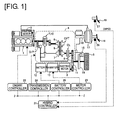
- FIG. 1 is a schematic diagram of a drive train of a hybrid vehicle equipped with the power plant for a vehicle of embodiment 1, and a system for controlling the entirety of the drive train.
- An engine 1 and an electric motor 2 are mounted in the hybrid vehicle of Figure 1 as power sources, the engine 1 being started by a starter motor 3.
- the engine 1 is drive-coupled to a drive wheel 5 via a V-belt-type continuously variable transmission 4 so as to be able to be decoupled as appropriate from the drive wheel 5.
- V-belt-type continuously variable transmission 4 A generic description of the V-belt-type continuously variable transmission 4 is given below.
- the V-belt-type continuously variable transmission 4 is a continuously variable transmission CVT configured from a variator comprising a primary pulley 6, a secondary pulley 7, and a V-belt 8 bridging the pulleys 6, 7.
- the primary pulley 6 is linked to a crankshaft, which is an output shaft of the engine 1, interposed by a torque converter T/C to which a lock-up clutch is attached, and the secondary pulley 7 is linked to the drive wheel 5 interposed by a clutch CL and a final gear group 9 in the stated order.
- the electric motor 2 is constantly coupled to the drive wheel 5 interposed by a final gear group 11, the electric motor 2 driving the drive wheel 5 using electric power from a battery 12, and an inverter 13 being interposed therebetween.
- the inverter 13 converts direct-current electric power from the battery 12 into alternating-current electric power and supplies this power to the electric motor 2, and, by reducing the electric power supplied to the electric motor 2, controls the driving power and the rotational direction of the electric motor 2.
- the electric motor 2 also functions as a generator in addition to the motor driving described above, and is made available for use in regenerative braking, which is described in detail below.
- the inverter 13 places a load generated by a regenerative braking force distribution on the electric motor 2, whereby the electric motor 2 is made to act as a generator and the power generated by the drive motor 2 is stored in the battery 12.
- the clutch CL is released and the electric motor 2 is driven while the engine 1 is in a stopped state, whereby only the power from the electric motor 2 reaches the drive wheel 5 via the final gear group 11, and the hybrid vehicle travels in an electric travel mode (EV mode) under the power of the electric motor alone.
- EV mode electric travel mode
- a brake disc 14 rotating together with the drive wheel 5 is clamped by a caliper 15 to apply braking, whereby the objective is achieved.
- the caliper 15 is connected to a master cylinder 18 that moves in response to the force produced by a driver depressing a brake pedal 16 and outputs brake hydraulic pressure corresponding to the brake pedal depressing force boosted by a negative-pressure booster 17, the caliper 15 being moved by the brake hydraulic pressure and applying braking to the brake disc 14.
- the vehicle wheel 5 is driven by torque in accordance with a drive force command that the driver issues by depressing an accelerator 19, the hybrid vehicle traveling under the drive force demanded by the driver.
- Hybrid controller 21 Selection of the travel mode of the hybrid vehicle, control of the output of the engine 1, control of the rotational direction and output of the electric motor 2, control of the gear-changing of the continuously variable transmission 4, control of the engagement and release of the clutch CL, and control of the charging and discharging of the battery 12 are each performed by a hybrid controller 21.
- the hybrid controller 21 correspondingly performs these controls via an engine controller 22, a motor controller 23, a variable transmission controller 24, and a battery controller 25.
- a signal from a brake switch 26, which is a normally open switch for switching from OFF to ON during braking by depression of the brake pedal 16, and a signal from an accelerator position sensor 27 for detecting the amount of depression of the accelerator (accelerator position) APO are inputted to the hybrid controller 21.
- the hybrid controller 21 furthermore passes internal information back and forth between the engine controller 22, the motor controller 23, the variable transmission controller 24, and the battery controller 25.
- the engine controller 22 controls the output of the engine 1 in response to commands from the hybrid controller 21, and the motor controller 23 controls the rotational direction and output of the electric motor 2 via the inverter 13 in response to commands from the hybrid controller 21.
- the variable transmission controller 24 controls the gear-changing of the continuously variable transmission 4 (V-belt-type continuously variable transmission mechanism) and controls the engagement and release of the clutch CL in response to commands from the hybrid controller 21, the controlling being performed using, as a medium, oil from an oil pump O/P by which the engine 1 is driven.
- the battery controller 25 controls the charging and discharging of the battery 12 in response to commands from the hybrid controller 21.
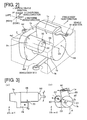
- FIG. 2 is a schematic perspective view of a state in which the power plant for a vehicle of embodiment 1 is mounted in the vehicle. Descriptions for the drive shaft and the like are not given.
- the engine 1, the continuously variable transmission 4, and the electric motor 2 are described below as a single power plant.
- the power plant is supported by a pendulum scheme having mounts M1, M2 from which the power plant is suspended, the mounts M1, M2 being provided above the center of gravity of the power plant, and a torque rod TR for restricting movement of the power plant along a longitudinal vehicle direction, the torque rod TR being provided below the center of gravity of the power plant.
- an x direction is defined as the longitudinal vehicle direction
- a y direction is defined as a widthwise vehicle direction
- a z direction is defined as a vertical vehicle direction.
- the power plant may be supported by any other method, so long as the relative positional relationship between the engine 1, the continuously variable transmission 4, and the electric motor 2 remains the same.
- the engine 1 has an engine block EB comprising a cylinder block 1a in which a cylinder chamber is formed and a crank case 1b in which the crankshaft is mounted.
- a variable transmission housing 4a in which the continuously variable transmission 4 is mounted is attached to the left side of the engine block EB along the y direction.
- the variable transmission housing 4a has a bulging part 4a1 bulging radially outward from the engine block as viewed in the y direction, the electric motor 2 being attached to an engine attachment surface 4a2 of the bulging part 4a1.
- the engine 1 and the electric motor 2 are attached to the engine attachment surface 4a2.
- a motor rotating shaft 02 of the electric motor 2 is disposed parallel to a crankshaft 01 of the engine 1.
- the electric motor 2 has a cylindrical motor housing 2a in which a stator and a rotor are accommodated.
- the motor housing 2a is assembled on the engine attachment surface 4a2of the variable transmission housing 4a.
- the electric motor 2 in the present embodiment is much larger than ordinary auxiliary equipment, making it difficult to cantilever the electric motor 2 using the variable transmission housing 4a. Therefore, a gusset 30, which is a reinforced connecting member, is provided between the motor housing 2a and the engine block EB (crank case 1b).
- An anchor point 03 which is a part where the gusset 30 and the engine block EB are connected, is connected by a bolt or the like, and acts as a swinging pivot when the motor housing 2a swings, as described below.
- the electric motor 2 constitutes a support structure supporting the variable transmission housing 4a and the gusset 30, and minimizes the generation of vibration.
- Figure 3 is a schematic view of the power plant for a vehicle of embodiment 1.
- Figure 4 is a schematic view of the power plant for a vehicle of a comparative example.
- Figures 3(a) and 4(a) are front views as viewed in the z direction
- Figures 3(b) and 4(b) are side views as viewed in the y direction.
- the comparative example is the same as embodiment 1, except that the position of the anchor point 03 is higher than in embodiment 1.
- the center of gravity of the electric motor 2 including the gusset 30 is positioned approximately on the motor rotating shaft 02.
- a line connecting the center of gravity of the electric motor 2 and the anchor point 03 is defined as a first line p1 extending along an A direction, and a line connecting from the center of gravity of the electric motor 2 to the anchor point 03 in the comparative example is defined as a second line p2 extending along a B direction.
- the B direction in the present embodiment is the direction in which the electric motor 2 maximally vibrates due to vibration of the engine 1 when the electric motor 2 is cantilevered in the absence of a gusset 30; the components along the longitudinal vehicle direction are typically large.
- the direction of vibration produced in the mounts M1, M2 along the longitudinal vehicle direction in the present embodiment is defined as an E direction.
- the B direction and the E direction may generally be considered to be the same direction, or may be considered to be slightly different directions due to various design parameters; however, these stipulations are not given by way of any particular limitation.
- FIG. 5 is a schematic plan view of the state of vibration of the power plant when engine vibration is generated in the comparative example.
- the electric motor 2 when the electric motor 2 is cantilevered, the electric motor 2 strongly vibrates along the B direction; therefore, the gusset 30 is provided between the electric motor 2 and the engine 1, and the anchor point 03 is disposed on the second line p2.
- a large portion of the force produced by the vibration of the electric motor 2 may be received by the engine block via the gusset 30.
- the engine block may be caused to flex due to this received force, resulting in strong vibration of the entire power plant, and it was evident that the vibration could not be minimized to a reasonable level.
- Figure 6 is a side view of the circumstances of vibration when vibration is generated in the power plant for a vehicle of embodiment 1
- Figure 7 is a side view of forces when vibration is generated in the power plant for a vehicle of embodiment 1. Due to engine vibration, the electric motor 2 vibrates along the B direction. Because the first line p1 and the second line p2 intersect at an angle ⁇ near the clamp point 03, the electric motor 2, in such circumstances, tracks along the B direction in a swinging movement about the anchor point 03, and performs the swinging movement shown by the C direction in Figure 6 .
- A-direction force received from the electric motor 2 by the engine block EB via the gusset 30 due to vibration is dispersed into an E-direction component and an F-direction component, when looking at the mount M1. Accordingly, vibration along the longitudinal direction is minimized, and vibration along the vertical direction is not recognized as becoming worse because such vibrations are not readily perceived by the driver as discomforting sensations.
- the electric motor 2 swings about the anchor point 03, whereby vibration can be absorbed, the force transmitted to the engine block EB-side is minimized, and increases in the vibration of the entire power plant can be avoided.
- Figure 8 is a schematic side view for illustrating the positional relationship between a first line and a second line in embodiment 1.
- Figure 8(a) illustrates the positional relationship in embodiment 1
- Figure 8(b) illustrates the positional relationship in a second comparative example.
- angle ⁇ is set so that the first line p1 passes on the far side of the second line p2 relative to the crankshaft 01.
- the source of shaking when the engine block EB vibrates is a rolling movement around the crankshaft 01, and because the cylinder block 1a set apart from the crankshaft 01 swings about the crankshaft 01 to a greater degree than does the crank case 1b, the cylinder block 1a readily vibrates strongly.
- the direction of vibration of the cylinder block 1a in such circumstances is defined as J.
- the anchor point 03 of the gusset 30 in embodiment 1 is set so as to pass closer to the crankshaft 01 than does the second line p2 so that the angle described by the first line p1 and the direction J of vibration is made larger, dispersing the force of the vibration produced between the anchor point 03 and the motor housing 2a.
- Figure 9 is a schematic view of the power plant for a vehicle of embodiment 2.
- Figure 9(a) is a plan view viewed in the z direction
- Figure 9(b) is a side view viewed in the y direction.
- the gusset 30 is provided perpendicularly to the crankshaft 01 (or the motor rotating shaft 02).
- embodiment 2 differs in that, when viewed in the z direction, the first line p1 is configured so as to intersect a plane F orthogonal to the crankshaft 01 and inclusive of the center of gravity of the electric motor 2, the first line p1 intersecting the plane F at an angle ⁇ that is smaller than angle ⁇ .
- Figure 10 is a plan view of forces when vibration is generated in the power plant for a vehicle of embodiment 2.
- the direction in which the first line p1 extends is defined as a G direction.
- the electric motor 2 is caused to vibrate along the B direction (vibrate within the plane F) due to engine vibration. Because the first line p1 intersects the plane F at an angle ⁇ , movement of the electric motor 2 along the B direction in such circumstances is dispersed in the G direction and the direction of the motor rotating shaft 02. Accordingly, the input of force to the engine block EB due to vibration can be minimized.
- angle ⁇ is preferably smaller than angle ⁇ .
- force along the direction of the motor rotating shaft 02 acts on the engine attachment surface 4a2 of the variable transmission housing 4a, and force along a direction orthogonal to the crankshaft 01 acts on the engine attachment surface 4a2 via the engine block EB. Vibration may thereby be produced such as would dislodge the engine block EB from the variable transmission housing 4a.
- the specific reason for such an event is that vibration such as is shown by arrow H in Figure 10 is generated between the crankshaft 01 and the engine attachment surface 4a2, whereby longitudinal vibration E in the mount M1 is increased, at which time the longitudinal vibration cannot be sufficiently suppressed.
- the first line p1 intersects the plane F at angle ⁇ , whereby vibration received by the engine block EB via the gusset 30 can be dissipated, and in particular, vibration in the longitudinal vehicle direction can be minimized.
- Setting the angle ⁇ smaller than angle ⁇ makes it possible to minimize vibration such as would dislodge the engine block EB from the variable transmission housing 4a, and in particular, to avoid worsening of vibration along the longitudinal vehicle direction due to excessive dispersing of the vibration.
- an example was illustrated in which an electric motor 2 is installed in a hybrid vehicle; however, the present example can similarly be applied to a case in which a large generator for supplying a drive current to a motor provided to another wheel is installed in the hybrid vehicle. Additionally, although an example of an electric motor was illustrated, the present invention may also be applied when a transfer is provided as a four-wheel drive unit.
- the gusset 30 is disposed further outward (further opposite the variable transmission housing 4a) along the motor rotating shaft 02 relative to the center of gravity of the electric motor 2; however, the gusset 30 may be positioned on the motor rotating shaft 02 so as to be co-located with the center of gravity of the electric motor 2.
- a continuously variable transmission 4 is installed in the hybrid vehicle.
- the present invention is not limited to the continuously variable transmission 4; a stepped variable transmission may be used instead.
- a planetary gear mechanism comprising a plurality of friction-coupling elements may be installed in the hybrid vehicle, as may a sub-transmission in which gears can be appropriately changed.
- a configuration for performing an engine restart using a starter motor 3 is illustrated in the embodiments, other configurations will suffice.
- a technique has been put to practical use in which, in a vehicle having an idling stop function, an alternator is replaced with a motor generator, an alternator function and an engine start-up function being added to the motor generator, whereby the engine restart is performed by the motor generator rather than by a starter motor when the engine is to be restarted from an idling stop.
- the present invention may be configured such that an engine restart is performed by a motor generator such as is described above.
Landscapes
- Engineering & Computer Science (AREA)
- Chemical & Material Sciences (AREA)
- Combustion & Propulsion (AREA)
- Mechanical Engineering (AREA)
- Transportation (AREA)
- General Engineering & Computer Science (AREA)
- Hybrid Electric Vehicles (AREA)
- Arrangement Or Mounting Of Propulsion Units For Vehicles (AREA)
Abstract
Description
- The present invention relates to a power plant for a vehicle in which at least an engine is mounted.
- The vehicle described in
Patent Document 1 is an example of a vehicle of such description. This vehicle comprises an engine and an electric motor as a power plant, and is of a type such that the engine is coupled to drive wheels via a continuously variable transmission and the electric motor is constantly linked to the drive wheels. In this vehicle, because sufficient support cannot be ensured merely by cantilevering the electric motor using the continuously variable transmission case, a housing of the electric motor and an engine block are connected by a support member (referred to as a "gusset" below), as shown inFigure 3 ofPatent Document 1, whereby the electric motor is supported. - Patent Document 1: Patent No.
3584680 - However, as a result of thoroughgoing investigations into the vibration characteristics obtained using the above configuration, a new problem was discovered in that, if the gusset is improperly arranged, vibration of the electric motor caused by engine vibration is transmitted back to the engine block via the gusset, whereby vibration of the power plant may increase.
- This problem is addressed by the present invention, it being an objective thereof to provide a power plant for a vehicle in which increases in the vibration of the power plant can be minimized even if vibration is transmitted from the engine to the electric motor.
- In order to achieve the above objective, the power plant for a vehicle of the present invention comprises an electric motor attached to a variable transmission housing attached to an engine, the electric motor being attached to the side of the variable transmission toward the engine and being connected to the engine interposed by an anchor point, a line that connects the center of gravity of the electric motor with the anchor point and a line that extends along a direction in which the electric motor would vibrate due to engine vibration in the absence of an anchor point intersecting when the engine is viewed in a crankshaft direction.
- Thus, when the electric motor vibrates, the linear movement in the absence of an anchor point can be converted into a swinging movement about the anchor point, and vibration of the power plant can be minimized by diffusing force received from the electric motor by the engine via the anchor point.
-
- [
Fig. 1 ] Schematic diagram of a drive train of a hybrid vehicle in which the power plant ofembodiment 1 is mounted, and a system for controlling the entirety of the drive train. - [
Fig. 2 ] Schematic perspective view of a state in which the power plant for a vehicle ofembodiment 1 is mounted in the vehicle. - [
Fig. 3 ] Schematic view of the power plant for a vehicle ofembodiment 1. - [
Fig. 4 ] Schematic view of the power plant for a vehicle of a comparative example. - [
Fig. 5 ] Schematic plan view of the state of vibration of the power plant when engine vibration is generated in the comparative example. - [
Fig. 6 ] Side view of the circumstances of vibration when vibration is generated in the power plant for a vehicle ofembodiment 1. - [
Fig. 7 ] Side view of forces when vibration is generated in the power plant for a vehicle ofembodiment 1. - [
Fig. 8 ] Schematic side view for illustrating the positional relationship between a first line and a second line inembodiment 1. - [
Fig. 9 ] Schematic view of the power plant for a vehicle ofembodiment 2. - [
Fig. 10 ] Plan view of forces when vibration is generated in the power plant for a vehicle ofembodiment 2. -
- 1
- Engine (power source)
- 1a
- Cylinder block
- 1b
- Crank case
- 2
- Electric motor (power source)
- 2a
- Motor housing
- 3
- Starter motor
- 4
- V-belt-type continuously variable transmission
- 4a
- Variable transmission housing
- 4a1
- Bulging part
- 4a2
- Engine attachment surface
- 5
- Drive wheel
- 30
- Gusset
- 01
- Crankshaft
- 02
- Motor rotating shaft
- 03
- Anchor point
- CL
- Clutch
- EB
- Engine block
- TR
- Torque rod
- M1, M2
- Mount
-
Figure 1 is a schematic diagram of a drive train of a hybrid vehicle equipped with the power plant for a vehicle ofembodiment 1, and a system for controlling the entirety of the drive train. Anengine 1 and anelectric motor 2 are mounted in the hybrid vehicle ofFigure 1 as power sources, theengine 1 being started by a starter motor 3. Theengine 1 is drive-coupled to a drive wheel 5 via a V-belt-type continuously variable transmission 4 so as to be able to be decoupled as appropriate from the drive wheel 5. A generic description of the V-belt-type continuously variable transmission 4 is given below. - The V-belt-type continuously variable transmission 4 is a continuously variable transmission CVT configured from a variator comprising a primary pulley 6, a secondary pulley 7, and a V-
belt 8 bridging the pulleys 6, 7. The primary pulley 6 is linked to a crankshaft, which is an output shaft of theengine 1, interposed by a torque converter T/C to which a lock-up clutch is attached, and the secondary pulley 7 is linked to the drive wheel 5 interposed by a clutch CL and afinal gear group 9 in the stated order. - Once the clutch CL has been engaged, power from the
engine 1 is inputted to the primary pulley 6 via the torque converter T/C before reaching the drive wheel 5 via the V-belt 8, the secondary pulley 7, the clutch CL, and thefinal gear group 9 in the stated order, the power being made available for the traveling of the hybrid vehicle. - The
electric motor 2 is constantly coupled to the drive wheel 5 interposed by afinal gear group 11, theelectric motor 2 driving the drive wheel 5 using electric power from abattery 12, and aninverter 13 being interposed therebetween. - The
inverter 13 converts direct-current electric power from thebattery 12 into alternating-current electric power and supplies this power to theelectric motor 2, and, by reducing the electric power supplied to theelectric motor 2, controls the driving power and the rotational direction of theelectric motor 2. - The
electric motor 2 also functions as a generator in addition to the motor driving described above, and is made available for use in regenerative braking, which is described in detail below. During regenerative braking, theinverter 13 places a load generated by a regenerative braking force distribution on theelectric motor 2, whereby theelectric motor 2 is made to act as a generator and the power generated by thedrive motor 2 is stored in thebattery 12. - In the hybrid vehicle of
embodiment 1, the clutch CL is released and theelectric motor 2 is driven while theengine 1 is in a stopped state, whereby only the power from theelectric motor 2 reaches the drive wheel 5 via thefinal gear group 11, and the hybrid vehicle travels in an electric travel mode (EV mode) under the power of the electric motor alone. By releasing the clutch at this time, power can be kept from being excessively consumed during EV traveling without co-rotating the stoppedengine 1. - When the clutch CL is engaged and the
engine 1 is started by the starter motor 3 while in the EV traveling state described above, power from theengine 1 reaches the drive wheel 5 via the torque converter T/C, the primary pulley 6, the V-belt 8, the secondary pulley 7, the clutch CL, and thefinal gear group 9 in the stated order, and the hybrid vehicle travels in a hybrid travel mode (HEV mode) under the power of theengine 1 and theelectric motor 2. - Once the hybrid vehicle is stopped from the travel state described above, or the hybrid vehicle is kept in this stopped state, a
brake disc 14 rotating together with the drive wheel 5 is clamped by acaliper 15 to apply braking, whereby the objective is achieved. Thecaliper 15 is connected to amaster cylinder 18 that moves in response to the force produced by a driver depressing abrake pedal 16 and outputs brake hydraulic pressure corresponding to the brake pedal depressing force boosted by a negative-pressure booster 17, thecaliper 15 being moved by the brake hydraulic pressure and applying braking to thebrake disc 14. Even when the hybrid vehicle is operating in the EV mode or the HEV mode, the vehicle wheel 5 is driven by torque in accordance with a drive force command that the driver issues by depressing anaccelerator 19, the hybrid vehicle traveling under the drive force demanded by the driver. - Selection of the travel mode of the hybrid vehicle, control of the output of the
engine 1, control of the rotational direction and output of theelectric motor 2, control of the gear-changing of the continuously variable transmission 4, control of the engagement and release of the clutch CL, and control of the charging and discharging of thebattery 12 are each performed by ahybrid controller 21. When so required, thehybrid controller 21 correspondingly performs these controls via anengine controller 22, amotor controller 23, avariable transmission controller 24, and abattery controller 25. - Therefore, a signal from a
brake switch 26, which is a normally open switch for switching from OFF to ON during braking by depression of thebrake pedal 16, and a signal from anaccelerator position sensor 27 for detecting the amount of depression of the accelerator (accelerator position) APO are inputted to thehybrid controller 21. Thehybrid controller 21 furthermore passes internal information back and forth between theengine controller 22, themotor controller 23, thevariable transmission controller 24, and thebattery controller 25. - The
engine controller 22 controls the output of theengine 1 in response to commands from thehybrid controller 21, and themotor controller 23 controls the rotational direction and output of theelectric motor 2 via theinverter 13 in response to commands from thehybrid controller 21. Thevariable transmission controller 24 controls the gear-changing of the continuously variable transmission 4 (V-belt-type continuously variable transmission mechanism) and controls the engagement and release of the clutch CL in response to commands from thehybrid controller 21, the controlling being performed using, as a medium, oil from an oil pump O/P by which theengine 1 is driven. Thebattery controller 25 controls the charging and discharging of thebattery 12 in response to commands from thehybrid controller 21. -
Figure 2 is a schematic perspective view of a state in which the power plant for a vehicle ofembodiment 1 is mounted in the vehicle. Descriptions for the drive shaft and the like are not given. Theengine 1, the continuously variable transmission 4, and theelectric motor 2 are described below as a single power plant. - The power plant is supported by a pendulum scheme having mounts M1, M2 from which the power plant is suspended, the mounts M1, M2 being provided above the center of gravity of the power plant, and a torque rod TR for restricting movement of the power plant along a longitudinal vehicle direction, the torque rod TR being provided below the center of gravity of the power plant. This minimizes the transmission of vibration from the power plant to the vehicle body and enhances ride quality while the vehicle is traveling. Below, an x direction is defined as the longitudinal vehicle direction, a y direction is defined as a widthwise vehicle direction, and a z direction is defined as a vertical vehicle direction. The power plant may be supported by any other method, so long as the relative positional relationship between the
engine 1, the continuously variable transmission 4, and theelectric motor 2 remains the same. - The
engine 1 has an engine block EB comprising acylinder block 1a in which a cylinder chamber is formed and a crankcase 1b in which the crankshaft is mounted. Avariable transmission housing 4a in which the continuously variable transmission 4 is mounted is attached to the left side of the engine block EB along the y direction. Thevariable transmission housing 4a has a bulging part 4a1 bulging radially outward from the engine block as viewed in the y direction, theelectric motor 2 being attached to an engine attachment surface 4a2 of the bulging part 4a1. Specifically, theengine 1 and theelectric motor 2 are attached to the engine attachment surface 4a2. - A
motor rotating shaft 02 of theelectric motor 2 is disposed parallel to acrankshaft 01 of theengine 1. Theelectric motor 2 has acylindrical motor housing 2a in which a stator and a rotor are accommodated. Themotor housing 2a is assembled on the engine attachment surface 4a2of thevariable transmission housing 4a. Theelectric motor 2 in the present embodiment is much larger than ordinary auxiliary equipment, making it difficult to cantilever theelectric motor 2 using thevariable transmission housing 4a. Therefore, agusset 30, which is a reinforced connecting member, is provided between themotor housing 2a and the engine block EB (crankcase 1b). Ananchor point 03, which is a part where thegusset 30 and the engine block EB are connected, is connected by a bolt or the like, and acts as a swinging pivot when themotor housing 2a swings, as described below. Theelectric motor 2 constitutes a support structure supporting thevariable transmission housing 4a and thegusset 30, and minimizes the generation of vibration. - The description of the power plant of
embodiment 1 below will be given using a comparative example for contrasting purposes.Figure 3 is a schematic view of the power plant for a vehicle ofembodiment 1.Figure 4 is a schematic view of the power plant for a vehicle of a comparative example.Figures 3(a) and4(a) are front views as viewed in the z direction, andFigures 3(b) and4(b) are side views as viewed in the y direction. The comparative example is the same asembodiment 1, except that the position of theanchor point 03 is higher than inembodiment 1. The center of gravity of theelectric motor 2 including thegusset 30 is positioned approximately on themotor rotating shaft 02. - As shown in
Figure 3(b) , when viewed in the y direction (the direction along thecrankshaft 01 of the engine 1), a line connecting the center of gravity of theelectric motor 2 and theanchor point 03 is defined as a first line p1 extending along an A direction, and a line connecting from the center of gravity of theelectric motor 2 to theanchor point 03 in the comparative example is defined as a second line p2 extending along a B direction. The B direction in the present embodiment is the direction in which theelectric motor 2 maximally vibrates due to vibration of theengine 1 when theelectric motor 2 is cantilevered in the absence of agusset 30; the components along the longitudinal vehicle direction are typically large. The direction of vibration produced in the mounts M1, M2 along the longitudinal vehicle direction in the present embodiment is defined as an E direction. The B direction and the E direction may generally be considered to be the same direction, or may be considered to be slightly different directions due to various design parameters; however, these stipulations are not given by way of any particular limitation. - When vibration along the longitudinal vehicle direction is produced, longitudinal vibration is also generated in the mounts M1, M2 supporting the power plant. Such vibrations are readily perceived by the driver as discomforting sensations. In the comparative example, it is thus an objective to provide effective restriction in the direction in which the electric motor maximally vibrates; the
anchor point 03 being provided on the second line p2 extending along the B direction. - However, thoroughgoing investigations performed by the inventor(s) yielded an unexpected result in the comparative example when vibration is generated, in regards to the nature of the vibration produced in the entire power plant.
Figure 5 is a schematic plan view of the state of vibration of the power plant when engine vibration is generated in the comparative example. As described above, when theelectric motor 2 is cantilevered, theelectric motor 2 strongly vibrates along the B direction; therefore, thegusset 30 is provided between theelectric motor 2 and theengine 1, and theanchor point 03 is disposed on the second line p2. In this case, a large portion of the force produced by the vibration of theelectric motor 2 may be received by the engine block via thegusset 30. The engine block may be caused to flex due to this received force, resulting in strong vibration of the entire power plant, and it was evident that the vibration could not be minimized to a reasonable level. - Therefore, in
embodiment 1, the position of theanchor point 03 is changed and the first line p1 and the second line p2 are configured so as to intersect at an angle α (a first angle). The action will be described below.Figure 6 is a side view of the circumstances of vibration when vibration is generated in the power plant for a vehicle ofembodiment 1, andFigure 7 is a side view of forces when vibration is generated in the power plant for a vehicle ofembodiment 1. Due to engine vibration, theelectric motor 2 vibrates along the B direction. Because the first line p1 and the second line p2 intersect at an angle α near theclamp point 03, theelectric motor 2, in such circumstances, tracks along the B direction in a swinging movement about theanchor point 03, and performs the swinging movement shown by the C direction inFigure 6 . - Specifically, as shown in
Figure 7(a) , A-direction force received from theelectric motor 2 by the engine block EB via thegusset 30 due to vibration is dispersed into an E-direction component and an F-direction component, when looking at the mount M1. Accordingly, vibration along the longitudinal direction is minimized, and vibration along the vertical direction is not recognized as becoming worse because such vibrations are not readily perceived by the driver as discomforting sensations. As shown inFigure 7(b) , when viewed as a power plant, theelectric motor 2 swings about theanchor point 03, whereby vibration can be absorbed, the force transmitted to the engine block EB-side is minimized, and increases in the vibration of the entire power plant can be avoided. - There follows a description in regard to the angle α being set so that the first line p1 passes closer to the
crankshaft 01 than does the second line p2.Figure 8 is a schematic side view for illustrating the positional relationship between a first line and a second line inembodiment 1.Figure 8(a) illustrates the positional relationship inembodiment 1, andFigure 8(b) illustrates the positional relationship in a second comparative example. In the second comparative example, angle α is set so that the first line p1 passes on the far side of the second line p2 relative to thecrankshaft 01. In this case, as shown inFigure 8(b) , the source of shaking when the engine block EB vibrates is a rolling movement around thecrankshaft 01, and because thecylinder block 1a set apart from thecrankshaft 01 swings about thecrankshaft 01 to a greater degree than does the crankcase 1b, thecylinder block 1a readily vibrates strongly. The direction of vibration of thecylinder block 1a in such circumstances is defined as J. - In this state, if the
anchor point 03 of thegusset 30 is positioned so as to pass on the far side of the second line p2 relative to thecrankshaft 01; i.e., if theanchor point 03 is provided at a position close to thecylinder block 1a, the angle described by the first line p1 and the direction J of vibration of thecylinder block 1a decreases, making it difficult to disperse the force of the vibration produced in the space bordered on one side by themotor housing 2a. Therefore, theanchor point 03 of thegusset 30 inembodiment 1 is set so as to pass closer to thecrankshaft 01 than does the second line p2 so that the angle described by the first line p1 and the direction J of vibration is made larger, dispersing the force of the vibration produced between theanchor point 03 and themotor housing 2a. - As described above, the action and effects enumerated below are obtained in
embodiment 1. - (1) A vehicle comprising:
- an
engine 1; - a continuously variable transmission 4 (transmission) attached to the
engine 1 and mounted in avariable transmission housing 4a; and - an electric motor 2 (electric motor) attached to an engine attachment surface 4a2 (to the side of the
variable transmission housing 4a toward the engine 1) and connected to theengine 1 interposed by ananchor point 03; - when the
engine 1 is viewed in acrankshaft 01 direction, a first line p1 connecting theanchor point 03 and the center of gravity of the electric motor 2 (electric motor) including agusset 30, and a second line p2 extending from the center of gravity of the electric motor 2 (electric motor) including agusset 30 along a B direction in which the electric motor 2 (electric motor) vibrates due to vibration of theengine 1 in the absence of ananchor point 03, intersecting at an angle α (a first angle).
Accordingly, theelectric motor 2 swings about theanchor point 03, whereby the vibration of theengine 1 and theelectric motor 2 can be absorbed, force transmitted to the engine 1-side can be minimized, and increases in the vibration of the entire power plant can be avoided. - an
- (2) The first line p1 passes closer to the
crankshaft 01 than does the second line p2.
Accordingly, the angle described by the second line p2 and a direction J of vibration of mainly thecylinder block 1a of the engine block EB can be increased, enabling the force of the vibration produced in the space bordered on one side by themotor housing 2a to be dispersed. - (3) The vehicle is a hybrid vehicle in which drive force can be outputted by the
electric motor 2.
Accordingly, taking theanchor point 03 of thegusset 30 into account when a large electric motor in which drive force can be ensured is installed in thevariable transmission housing 4a makes it possible to provide a power plant in which vibration is minimized. Theelectric motor 2 can easily be installed particularly in the case of a configuration in which theelectric motor 2 is installed on a shaft different from thecrankshaft 01 and drive force is imparted from theelectric motor 2 to a drive wheel. - (4) The power plant is supported by a pendulum scheme having mounts M1, M2 provided above the center of gravity of the power plant and a torque rod TR connected to the vehicle body below the center of gravity of the power plant.
Specifically, the power plant is supported by the pendulum scheme, whereby the transmission of vibration caused by rolling movement generated in the crankshaft to the vehicle body is minimized, and ride quality while the vehicle is traveling is enhanced. In such circumstances, theelectric motor 2 readily vibrates due to a component in a longitudinal vehicle direction; however, the first line p1 and the second line p2 intersect, whereby vibration of the entire power plant is minimized. - Next,
embodiment 2 will be described. The basic configuration is the same as inembodiment 1; therefore, only points of difference will be described.Figure 9 is a schematic view of the power plant for a vehicle ofembodiment 2.Figure 9(a) is a plan view viewed in the z direction, andFigure 9(b) is a side view viewed in the y direction. Inembodiment 1, when viewed in the z direction, thegusset 30 is provided perpendicularly to the crankshaft 01 (or the motor rotating shaft 02). However,embodiment 2 differs in that, when viewed in the z direction, the first line p1 is configured so as to intersect a plane F orthogonal to thecrankshaft 01 and inclusive of the center of gravity of theelectric motor 2, the first line p1 intersecting the plane F at an angle β that is smaller than angle α. - The action of the vibration in the present embodiment when viewed in the y direction is fundamentally the same as in
embodiment 1; therefore, the action when viewed in the z direction will be described in detail.Figure 10 is a plan view of forces when vibration is generated in the power plant for a vehicle ofembodiment 2. In this plan view, the direction in which the first line p1 extends is defined as a G direction. - The
electric motor 2 is caused to vibrate along the B direction (vibrate within the plane F) due to engine vibration. Because the first line p1 intersects the plane F at an angle β, movement of theelectric motor 2 along the B direction in such circumstances is dispersed in the G direction and the direction of themotor rotating shaft 02. Accordingly, the input of force to the engine block EB due to vibration can be minimized. - However, angle β is preferably smaller than angle α. Specifically, when the first line p1 intersects at angle β, force along the direction of the
motor rotating shaft 02 acts on the engine attachment surface 4a2 of thevariable transmission housing 4a, and force along a direction orthogonal to thecrankshaft 01 acts on the engine attachment surface 4a2 via the engine block EB. Vibration may thereby be produced such as would dislodge the engine block EB from thevariable transmission housing 4a. The specific reason for such an event is that vibration such as is shown by arrow H inFigure 10 is generated between thecrankshaft 01 and the engine attachment surface 4a2, whereby longitudinal vibration E in the mount M1 is increased, at which time the longitudinal vibration cannot be sufficiently suppressed. - As described above, the action and effects enumerated below are obtained in
embodiment 2. - (5) The first line p1 intersects a plane F orthogonal to the
crankshaft 01 of theengine 1 and inclusive of the center of gravity of theelectric motor 2, the first line p1 intersecting the plane F at an angle β (a second angle) that is smaller than angle α. - Specifically, the first line p1 intersects the plane F at angle β, whereby vibration received by the engine block EB via the
gusset 30 can be dissipated, and in particular, vibration in the longitudinal vehicle direction can be minimized. Setting the angle β smaller than angle α makes it possible to minimize vibration such as would dislodge the engine block EB from thevariable transmission housing 4a, and in particular, to avoid worsening of vibration along the longitudinal vehicle direction due to excessive dispersing of the vibration. - The present invention is described above on the basis of the embodiments. However, the present invention is not limited to the above configuration; other configurations are also included in the present invention.
- For example, in the embodiments, an example was illustrated in which an
electric motor 2 is installed in a hybrid vehicle; however, the present example can similarly be applied to a case in which a large generator for supplying a drive current to a motor provided to another wheel is installed in the hybrid vehicle. Additionally, although an example of an electric motor was illustrated, the present invention may also be applied when a transfer is provided as a four-wheel drive unit. - In
embodiment 1, thegusset 30 is disposed further outward (further opposite thevariable transmission housing 4a) along themotor rotating shaft 02 relative to the center of gravity of theelectric motor 2; however, thegusset 30 may be positioned on themotor rotating shaft 02 so as to be co-located with the center of gravity of theelectric motor 2. - An example is given in
embodiment 1 in which a continuously variable transmission 4 is installed in the hybrid vehicle. However, the present invention is not limited to the continuously variable transmission 4; a stepped variable transmission may be used instead. Additionally, instead of the clutch CL, a planetary gear mechanism comprising a plurality of friction-coupling elements may be installed in the hybrid vehicle, as may a sub-transmission in which gears can be appropriately changed. - Furthermore, although a configuration for performing an engine restart using a starter motor 3 is illustrated in the embodiments, other configurations will suffice. Specifically, in recent years, a technique has been put to practical use in which, in a vehicle having an idling stop function, an alternator is replaced with a motor generator, an alternator function and an engine start-up function being added to the motor generator, whereby the engine restart is performed by the motor generator rather than by a starter motor when the engine is to be restarted from an idling stop. The present invention may be configured such that an engine restart is performed by a motor generator such as is described above.
Claims (5)
- A power plant for a vehicle, characterized in comprising:an engine;a transmission attached to the engine and mounted in a transmission housing; andan electric motor attached to the side of the transmission housing toward the engine and connected to the engine interposed by an anchor point;when the engine is viewed in a crankshaft direction, a first line connecting the anchor point and the center of gravity of the electric motor, and a second line extending from the center of gravity of the electric motor along a direction in which the electric motor vibrates due to vibration of the engine in the absence of an anchor point, intersecting at a first angle.
- The power plant for a vehicle as in claim 1, the power plant for a vehicle being characterized in that
the first line intersects a plane orthogonal to the crankshaft of the engine and inclusive of the center of gravity of the electric motor, the first line intersecting the plane at a second angle that is smaller than the first angle. - The power plant for a vehicle as in claim 1 or 2, the power plant for a vehicle being characterized in that
the first line passes closer to the crankshaft than does the second line. - The power plant for a vehicle as in any of claims 1 through 3, the power plant for a vehicle being characterized in that
the vehicle is a hybrid vehicle in which drive force can be outputted by the electric motor. - The power plant for a vehicle as in any of claims 1 through 4, the power plant for a vehicle being characterized in that
the power plant is supported by a pendulum scheme having a mount provided above the center of gravity of the power plant and a torque rod connected to the vehicle body below the center of gravity of the power plant.
Applications Claiming Priority (2)
| Application Number | Priority Date | Filing Date | Title |
|---|---|---|---|
| JP2012260552 | 2012-11-29 | ||
| PCT/JP2013/078961 WO2014083984A1 (en) | 2012-11-29 | 2013-10-25 | Power plant for vehicle |
Publications (2)
| Publication Number | Publication Date |
|---|---|
| EP2927037A1 true EP2927037A1 (en) | 2015-10-07 |
| EP2927037A4 EP2927037A4 (en) | 2017-03-29 |
Family
ID=50827630
Family Applications (1)
| Application Number | Title | Priority Date | Filing Date |
|---|---|---|---|
| EP13859429.6A Withdrawn EP2927037A4 (en) | 2012-11-29 | 2013-10-25 | Power plant for vehicle |
Country Status (5)
| Country | Link |
|---|---|
| US (1) | US9376008B2 (en) |
| EP (1) | EP2927037A4 (en) |
| JP (1) | JP5971351B2 (en) |
| CN (1) | CN104812605B (en) |
| WO (1) | WO2014083984A1 (en) |
Cited By (2)
| Publication number | Priority date | Publication date | Assignee | Title |
|---|---|---|---|---|
| WO2019120828A1 (en) * | 2017-12-22 | 2019-06-27 | Renault S.A.S | Mount for an electric motor comprising an integrated duct, and power train comprising such a mount |
| WO2019149572A1 (en) * | 2018-02-02 | 2019-08-08 | Bayerische Motoren Werke Aktiengesellschaft | Hybrid drive assembly for a vehicle |
Families Citing this family (10)
| Publication number | Priority date | Publication date | Assignee | Title |
|---|---|---|---|---|
| EP2927037A4 (en) * | 2012-11-29 | 2017-03-29 | Nissan Motor Co., Ltd | Power plant for vehicle |
| SE537132C2 (en) * | 2013-05-30 | 2015-02-10 | BAE Systems Hägglunds Aktiebolag | Electric drive for driving a motor vehicle |
| JP6060878B2 (en) * | 2013-11-20 | 2017-01-18 | トヨタ自動車株式会社 | Vehicle with power transmission / reception unit |
| GB2532731A (en) * | 2014-11-25 | 2016-06-01 | Eric Hawksley Graeme | Hybrid power system |
| JP6722572B2 (en) * | 2016-12-02 | 2020-07-15 | ヤンマーパワーテクノロジー株式会社 | engine |
| JP2020078995A (en) * | 2018-11-13 | 2020-05-28 | 本田技研工業株式会社 | Drive unit |
| JP7238386B2 (en) | 2018-12-21 | 2023-03-14 | スズキ株式会社 | Drive system for hybrid vehicle |
| JP7183771B2 (en) * | 2018-12-21 | 2022-12-06 | スズキ株式会社 | Drive system for hybrid vehicle |
| WO2022168001A1 (en) * | 2021-02-05 | 2022-08-11 | Bombardier Recreational Products Inc. | All-terrain vehicle |
| US12558951B2 (en) | 2021-05-19 | 2026-02-24 | Nissan Motor Co., Ltd. | Drive unit |
Family Cites Families (29)
| Publication number | Priority date | Publication date | Assignee | Title |
|---|---|---|---|---|
| JPH0240935U (en) * | 1988-09-13 | 1990-03-20 | ||
| JPH0356837U (en) * | 1989-10-03 | 1991-05-31 | ||
| JPH03267527A (en) * | 1990-03-15 | 1991-11-28 | Mazda Motor Corp | Structure of accessary mounting device of engine |
| US5203293A (en) * | 1990-06-29 | 1993-04-20 | Mazda Motor Corporation | Auxiliary mechanism mounting structure for an engine |
| JPH0460119A (en) * | 1990-06-29 | 1992-02-26 | Mazda Motor Corp | Device for mounting engine auxiliary machinery |
| JP2650167B2 (en) * | 1991-06-24 | 1997-09-03 | 日産自動車株式会社 | Automotive power plant support equipment |
| US5195608A (en) * | 1991-08-13 | 1993-03-23 | Nissan Motor Co., Ltd. | Power plant for automotive vehicle |
| US6170597B1 (en) * | 1997-04-30 | 2001-01-09 | Yamaha Hatsudoki Kabushiki Kaisha | Transmission for offroad vehicle |
| JP3584680B2 (en) * | 1997-06-06 | 2004-11-04 | 日産自動車株式会社 | Hybrid vehicle drive system of internal combustion engine and electric motor |
| JPH10339185A (en) * | 1997-06-06 | 1998-12-22 | Nissan Motor Co Ltd | Combined vehicle drive device of internal combustion engine and electric motor and control method therefor |
| JP3533979B2 (en) * | 1999-03-05 | 2004-06-07 | 日産自動車株式会社 | Power head mounting structure for electric vehicles |
| JP3613088B2 (en) * | 1999-09-10 | 2005-01-26 | 日産自動車株式会社 | Vehicle drive unit support device |
| JP2001173544A (en) * | 1999-12-17 | 2001-06-26 | Isuzu Motors Ltd | Engine starter mounting structure |
| US6727670B1 (en) * | 2002-12-12 | 2004-04-27 | Ford Global Technologies, Llc | Battery current limiter for a high voltage battery pack in a hybrid electric vehicle powertrain |
| JP4433142B2 (en) | 2003-09-02 | 2010-03-17 | 倉敷化工株式会社 | Anti-vibration mounting device |
| JP4483819B2 (en) * | 2005-04-28 | 2010-06-16 | 株式会社豊田中央研究所 | Power transmission system |
| US7797089B2 (en) * | 2006-03-30 | 2010-09-14 | Ford Global Technologies, Llc | System and method for managing a power source in a vehicle |
| JP2008105550A (en) * | 2006-10-25 | 2008-05-08 | Honda Motor Co Ltd | Power equipment |
| US8474555B2 (en) * | 2009-04-15 | 2013-07-02 | Nissan Motor Co., Ltd. | Vehicle component mounting structure |
| FR2948073B1 (en) * | 2009-07-15 | 2011-10-28 | Inst Francais Du Petrole | SYSTEM FOR DRIVING TRAINING OF A HYBRID MOTOR VEHICLE AND METHOD FOR DRIVING SUCH A VEHICLE |
| DE102009034510A1 (en) * | 2009-07-24 | 2011-04-14 | Bayerische Motoren Werke Aktiengesellschaft | Vehicle with a supercharged combustion engine and method for operating a vehicle with a supercharged combustion engine |
| CN101700737B (en) * | 2009-10-12 | 2011-03-23 | 力帆实业(集团)股份有限公司 | Generator control system of range-extended electric car |
| JP5736850B2 (en) * | 2011-03-04 | 2015-06-17 | 日産自動車株式会社 | Drive device for hybrid vehicle |
| EP2710509A4 (en) * | 2011-05-18 | 2015-02-25 | Nokia Corp | SECURE PRIMER WITH TRUSTED COMPUTER GROUP PLATFORM REGISTERS |
| US8452473B2 (en) * | 2011-06-02 | 2013-05-28 | GM Global Technology Operations LLC | Method and apparatus for managing torque in a hybrid powertrain system |
| US8746394B2 (en) * | 2011-08-22 | 2014-06-10 | Kubota Corporation | Working vehicle |
| JP5929435B2 (en) * | 2012-04-04 | 2016-06-08 | スズキ株式会社 | Hybrid vehicle power unit |
| JP5604651B2 (en) * | 2012-07-02 | 2014-10-08 | 株式会社ソフイア | Game machine |
| EP2927037A4 (en) * | 2012-11-29 | 2017-03-29 | Nissan Motor Co., Ltd | Power plant for vehicle |
-
2013
- 2013-10-25 EP EP13859429.6A patent/EP2927037A4/en not_active Withdrawn
- 2013-10-25 WO PCT/JP2013/078961 patent/WO2014083984A1/en not_active Ceased
- 2013-10-25 JP JP2014550092A patent/JP5971351B2/en not_active Expired - Fee Related
- 2013-10-25 US US14/439,243 patent/US9376008B2/en not_active Expired - Fee Related
- 2013-10-25 CN CN201380061854.4A patent/CN104812605B/en not_active Expired - Fee Related
Cited By (3)
| Publication number | Priority date | Publication date | Assignee | Title |
|---|---|---|---|---|
| WO2019120828A1 (en) * | 2017-12-22 | 2019-06-27 | Renault S.A.S | Mount for an electric motor comprising an integrated duct, and power train comprising such a mount |
| FR3075699A1 (en) * | 2017-12-22 | 2019-06-28 | Renault S.A.S. | ELECTRIC MOTOR SUPPORT COMPRISING AN INTEGRATED CONDUIT AND MOTOR POWER PACK COMPRISING SUCH A SUPPORT |
| WO2019149572A1 (en) * | 2018-02-02 | 2019-08-08 | Bayerische Motoren Werke Aktiengesellschaft | Hybrid drive assembly for a vehicle |
Also Published As
| Publication number | Publication date |
|---|---|
| JP5971351B2 (en) | 2016-08-17 |
| EP2927037A4 (en) | 2017-03-29 |
| US9376008B2 (en) | 2016-06-28 |
| CN104812605B (en) | 2018-03-30 |
| WO2014083984A1 (en) | 2014-06-05 |
| US20150291018A1 (en) | 2015-10-15 |
| JPWO2014083984A1 (en) | 2017-01-05 |
| CN104812605A (en) | 2015-07-29 |
Similar Documents
| Publication | Publication Date | Title |
|---|---|---|
| US9376008B2 (en) | Power plant for a vehicle | |
| US20160257297A1 (en) | Control system for hybrid vehicle | |
| JP6374431B2 (en) | Drive control mechanism and drive control device | |
| CN102092272A (en) | Power assembly system for plug-in hybrid electric vehicle | |
| EP3273101A1 (en) | Vehicle regenerative speed control device | |
| WO2012011495A1 (en) | Hybrid-vehicle control device | |
| JP6070855B2 (en) | Control device for hybrid vehicle | |
| JP5652479B2 (en) | Vehicle and vehicle control method | |
| JP3909328B2 (en) | Control method of vehicle hybrid drive | |
| JP5644868B2 (en) | Vehicle and vehicle control method | |
| KR101429423B1 (en) | Power transmission apparatus for hybrid car | |
| JP2018052320A (en) | Control device and control method for hybrid vehicle system | |
| JP6444488B2 (en) | Control device for hybrid vehicle | |
| KR101791124B1 (en) | Power transmission structure of hybrid car having two motors-three clutches | |
| JP2010269642A (en) | Braking control device for hybrid vehicle | |
| CN105835680A (en) | Drivetrain system of hybrid vehicle | |
| US20140038772A1 (en) | Traction Control System For A Hybrid Vehicle | |
| JP2003285671A (en) | Hybrid vehicle | |
| JP2016175531A (en) | Control device for hybrid vehicle | |
| JP2002174305A (en) | Auxiliary drive | |
| JP6237454B2 (en) | Vehicle power plant | |
| JP3704996B2 (en) | Control device for hybrid vehicle | |
| JP2016008015A (en) | Vehicle start control device | |
| JP2012224304A (en) | Damping control device of vehicle | |
| JP2002204503A (en) | Control device for vehicle power unit |
Legal Events
| Date | Code | Title | Description |
|---|---|---|---|
| PUAI | Public reference made under article 153(3) epc to a published international application that has entered the european phase |
Free format text: ORIGINAL CODE: 0009012 |
|
| 17P | Request for examination filed |
Effective date: 20150625 |
|
| AK | Designated contracting states |
Kind code of ref document: A1 Designated state(s): AL AT BE BG CH CY CZ DE DK EE ES FI FR GB GR HR HU IE IS IT LI LT LU LV MC MK MT NL NO PL PT RO RS SE SI SK SM TR |
|
| AX | Request for extension of the european patent |
Extension state: BA ME |
|
| DAX | Request for extension of the european patent (deleted) | ||
| RA4 | Supplementary search report drawn up and despatched (corrected) |
Effective date: 20170224 |
|
| RIC1 | Information provided on ipc code assigned before grant |
Ipc: B60K 6/26 20071001AFI20170220BHEP Ipc: F02D 29/02 20060101ALI20170220BHEP Ipc: B60K 6/543 20071001ALI20170220BHEP Ipc: B60K 5/04 20060101ALI20170220BHEP Ipc: B60K 6/48 20071001ALI20170220BHEP Ipc: B60K 17/04 20060101ALI20170220BHEP Ipc: B60K 1/00 20060101ALI20170220BHEP Ipc: B60K 5/12 20060101ALI20170220BHEP Ipc: B60K 1/04 20060101ALI20170220BHEP |
|
| STAA | Information on the status of an ep patent application or granted ep patent |
Free format text: STATUS: THE APPLICATION HAS BEEN WITHDRAWN |
|
| 18W | Application withdrawn |
Effective date: 20200211 |