EP2926990B1 - Verfahren zum bereitstellen von abstandshaltern - Google Patents
Verfahren zum bereitstellen von abstandshaltern Download PDFInfo
- Publication number
- EP2926990B1 EP2926990B1 EP15000946.2A EP15000946A EP2926990B1 EP 2926990 B1 EP2926990 B1 EP 2926990B1 EP 15000946 A EP15000946 A EP 15000946A EP 2926990 B1 EP2926990 B1 EP 2926990B1
- Authority
- EP
- European Patent Office
- Prior art keywords
- component
- passages
- spacers
- sheetlike structure
- fabric
- Prior art date
- Legal status (The legal status is an assumption and is not a legal conclusion. Google has not performed a legal analysis and makes no representation as to the accuracy of the status listed.)
- Active
Links
Images

Classifications
-
- B—PERFORMING OPERATIONS; TRANSPORTING
- B29—WORKING OF PLASTICS; WORKING OF SUBSTANCES IN A PLASTIC STATE IN GENERAL
- B29C—SHAPING OR JOINING OF PLASTICS; SHAPING OF MATERIAL IN A PLASTIC STATE, NOT OTHERWISE PROVIDED FOR; AFTER-TREATMENT OF THE SHAPED PRODUCTS, e.g. REPAIRING
- B29C65/00—Joining or sealing of preformed parts, e.g. welding of plastics materials; Apparatus therefor
- B29C65/70—Joining or sealing of preformed parts, e.g. welding of plastics materials; Apparatus therefor by moulding
-
- B—PERFORMING OPERATIONS; TRANSPORTING
- B29—WORKING OF PLASTICS; WORKING OF SUBSTANCES IN A PLASTIC STATE IN GENERAL
- B29C—SHAPING OR JOINING OF PLASTICS; SHAPING OF MATERIAL IN A PLASTIC STATE, NOT OTHERWISE PROVIDED FOR; AFTER-TREATMENT OF THE SHAPED PRODUCTS, e.g. REPAIRING
- B29C73/00—Repairing of articles made from plastics or substances in a plastic state, e.g. of articles shaped or produced by using techniques covered by this subclass or subclass B29D
-
- B—PERFORMING OPERATIONS; TRANSPORTING
- B32—LAYERED PRODUCTS
- B32B—LAYERED PRODUCTS, i.e. PRODUCTS BUILT-UP OF STRATA OF FLAT OR NON-FLAT, e.g. CELLULAR OR HONEYCOMB, FORM
- B32B27/00—Layered products comprising a layer of synthetic resin
-
- B—PERFORMING OPERATIONS; TRANSPORTING
- B32—LAYERED PRODUCTS
- B32B—LAYERED PRODUCTS, i.e. PRODUCTS BUILT-UP OF STRATA OF FLAT OR NON-FLAT, e.g. CELLULAR OR HONEYCOMB, FORM
- B32B27/00—Layered products comprising a layer of synthetic resin
- B32B27/06—Layered products comprising a layer of synthetic resin as the main or only constituent of a layer, which is next to another layer of the same or of a different material
-
- B—PERFORMING OPERATIONS; TRANSPORTING
- B32—LAYERED PRODUCTS
- B32B—LAYERED PRODUCTS, i.e. PRODUCTS BUILT-UP OF STRATA OF FLAT OR NON-FLAT, e.g. CELLULAR OR HONEYCOMB, FORM
- B32B27/00—Layered products comprising a layer of synthetic resin
- B32B27/30—Layered products comprising a layer of synthetic resin comprising vinyl (co)polymers; comprising acrylic (co)polymers
- B32B27/304—Layered products comprising a layer of synthetic resin comprising vinyl (co)polymers; comprising acrylic (co)polymers comprising vinyl halide (co)polymers, e.g. PVC, PVDC, PVF, PVDF
-
- B—PERFORMING OPERATIONS; TRANSPORTING
- B32—LAYERED PRODUCTS
- B32B—LAYERED PRODUCTS, i.e. PRODUCTS BUILT-UP OF STRATA OF FLAT OR NON-FLAT, e.g. CELLULAR OR HONEYCOMB, FORM
- B32B27/00—Layered products comprising a layer of synthetic resin
- B32B27/32—Layered products comprising a layer of synthetic resin comprising polyolefins
- B32B27/322—Layered products comprising a layer of synthetic resin comprising polyolefins comprising halogenated polyolefins, e.g. PTFE
-
- B—PERFORMING OPERATIONS; TRANSPORTING
- B32—LAYERED PRODUCTS
- B32B—LAYERED PRODUCTS, i.e. PRODUCTS BUILT-UP OF STRATA OF FLAT OR NON-FLAT, e.g. CELLULAR OR HONEYCOMB, FORM
- B32B3/00—Layered products comprising a layer with external or internal discontinuities or unevennesses, or a layer of non-planar shape; Layered products comprising a layer having particular features of form
-
- B—PERFORMING OPERATIONS; TRANSPORTING
- B32—LAYERED PRODUCTS
- B32B—LAYERED PRODUCTS, i.e. PRODUCTS BUILT-UP OF STRATA OF FLAT OR NON-FLAT, e.g. CELLULAR OR HONEYCOMB, FORM
- B32B3/00—Layered products comprising a layer with external or internal discontinuities or unevennesses, or a layer of non-planar shape; Layered products comprising a layer having particular features of form
- B32B3/02—Layered products comprising a layer with external or internal discontinuities or unevennesses, or a layer of non-planar shape; Layered products comprising a layer having particular features of form characterised by features of form at particular places, e.g. in edge regions
-
- B—PERFORMING OPERATIONS; TRANSPORTING
- B32—LAYERED PRODUCTS
- B32B—LAYERED PRODUCTS, i.e. PRODUCTS BUILT-UP OF STRATA OF FLAT OR NON-FLAT, e.g. CELLULAR OR HONEYCOMB, FORM
- B32B3/00—Layered products comprising a layer with external or internal discontinuities or unevennesses, or a layer of non-planar shape; Layered products comprising a layer having particular features of form
- B32B3/26—Layered products comprising a layer with external or internal discontinuities or unevennesses, or a layer of non-planar shape; Layered products comprising a layer having particular features of form characterised by a particular shape of the outline of the cross-section of a continuous layer; characterised by a layer with cavities or internal voids ; characterised by an apertured layer
- B32B3/30—Layered products comprising a layer with external or internal discontinuities or unevennesses, or a layer of non-planar shape; Layered products comprising a layer having particular features of form characterised by a particular shape of the outline of the cross-section of a continuous layer; characterised by a layer with cavities or internal voids ; characterised by an apertured layer characterised by a layer formed with recesses or projections, e.g. hollows, grooves, protuberances, ribs
-
- B—PERFORMING OPERATIONS; TRANSPORTING
- B32—LAYERED PRODUCTS
- B32B—LAYERED PRODUCTS, i.e. PRODUCTS BUILT-UP OF STRATA OF FLAT OR NON-FLAT, e.g. CELLULAR OR HONEYCOMB, FORM
- B32B7/00—Layered products characterised by the relation between layers; Layered products characterised by the relative orientation of features between layers, or by the relative values of a measurable parameter between layers, i.e. products comprising layers having different physical, chemical or physicochemical properties; Layered products characterised by the interconnection of layers
-
- B—PERFORMING OPERATIONS; TRANSPORTING
- B32—LAYERED PRODUCTS
- B32B—LAYERED PRODUCTS, i.e. PRODUCTS BUILT-UP OF STRATA OF FLAT OR NON-FLAT, e.g. CELLULAR OR HONEYCOMB, FORM
- B32B7/00—Layered products characterised by the relation between layers; Layered products characterised by the relative orientation of features between layers, or by the relative values of a measurable parameter between layers, i.e. products comprising layers having different physical, chemical or physicochemical properties; Layered products characterised by the interconnection of layers
- B32B7/04—Interconnection of layers
- B32B7/12—Interconnection of layers using interposed adhesives or interposed materials with bonding properties
-
- C—CHEMISTRY; METALLURGY
- C09—DYES; PAINTS; POLISHES; NATURAL RESINS; ADHESIVES; COMPOSITIONS NOT OTHERWISE PROVIDED FOR; APPLICATIONS OF MATERIALS NOT OTHERWISE PROVIDED FOR
- C09J—ADHESIVES; NON-MECHANICAL ASPECTS OF ADHESIVE PROCESSES IN GENERAL; ADHESIVE PROCESSES NOT PROVIDED FOR ELSEWHERE; USE OF MATERIALS AS ADHESIVES
- C09J5/00—Adhesive processes in general; Adhesive processes not provided for elsewhere, e.g. relating to primers
-
- F—MECHANICAL ENGINEERING; LIGHTING; HEATING; WEAPONS; BLASTING
- F16—ENGINEERING ELEMENTS AND UNITS; GENERAL MEASURES FOR PRODUCING AND MAINTAINING EFFECTIVE FUNCTIONING OF MACHINES OR INSTALLATIONS; THERMAL INSULATION IN GENERAL
- F16B—DEVICES FOR FASTENING OR SECURING CONSTRUCTIONAL ELEMENTS OR MACHINE PARTS TOGETHER, e.g. NAILS, BOLTS, CIRCLIPS, CLAMPS, CLIPS OR WEDGES; JOINTS OR JOINTING
- F16B11/00—Connecting constructional elements or machine parts by sticking or pressing them together, e.g. cold pressure welding
- F16B11/006—Connecting constructional elements or machine parts by sticking or pressing them together, e.g. cold pressure welding by gluing
-
- B—PERFORMING OPERATIONS; TRANSPORTING
- B29—WORKING OF PLASTICS; WORKING OF SUBSTANCES IN A PLASTIC STATE IN GENERAL
- B29K—INDEXING SCHEME ASSOCIATED WITH SUBCLASSES B29B, B29C OR B29D, RELATING TO MOULDING MATERIALS OR TO MATERIALS FOR MOULDS, REINFORCEMENTS, FILLERS OR PREFORMED PARTS, e.g. INSERTS
- B29K2063/00—Use of EP, i.e. epoxy resins or derivatives thereof, as moulding material
-
- B—PERFORMING OPERATIONS; TRANSPORTING
- B32—LAYERED PRODUCTS
- B32B—LAYERED PRODUCTS, i.e. PRODUCTS BUILT-UP OF STRATA OF FLAT OR NON-FLAT, e.g. CELLULAR OR HONEYCOMB, FORM
- B32B2307/00—Properties of the layers or laminate
- B32B2307/70—Other properties
- B32B2307/732—Dimensional properties
-
- B—PERFORMING OPERATIONS; TRANSPORTING
- B32—LAYERED PRODUCTS
- B32B—LAYERED PRODUCTS, i.e. PRODUCTS BUILT-UP OF STRATA OF FLAT OR NON-FLAT, e.g. CELLULAR OR HONEYCOMB, FORM
- B32B2307/00—Properties of the layers or laminate
- B32B2307/70—Other properties
- B32B2307/732—Dimensional properties
- B32B2307/734—Dimensional stability
-
- B—PERFORMING OPERATIONS; TRANSPORTING
- B32—LAYERED PRODUCTS
- B32B—LAYERED PRODUCTS, i.e. PRODUCTS BUILT-UP OF STRATA OF FLAT OR NON-FLAT, e.g. CELLULAR OR HONEYCOMB, FORM
- B32B2419/00—Buildings or parts thereof
-
- B—PERFORMING OPERATIONS; TRANSPORTING
- B32—LAYERED PRODUCTS
- B32B—LAYERED PRODUCTS, i.e. PRODUCTS BUILT-UP OF STRATA OF FLAT OR NON-FLAT, e.g. CELLULAR OR HONEYCOMB, FORM
- B32B27/00—Layered products comprising a layer of synthetic resin
- B32B27/06—Layered products comprising a layer of synthetic resin as the main or only constituent of a layer, which is next to another layer of the same or of a different material
- B32B27/08—Layered products comprising a layer of synthetic resin as the main or only constituent of a layer, which is next to another layer of the same or of a different material of synthetic resin
-
- C—CHEMISTRY; METALLURGY
- C09—DYES; PAINTS; POLISHES; NATURAL RESINS; ADHESIVES; COMPOSITIONS NOT OTHERWISE PROVIDED FOR; APPLICATIONS OF MATERIALS NOT OTHERWISE PROVIDED FOR
- C09J—ADHESIVES; NON-MECHANICAL ASPECTS OF ADHESIVE PROCESSES IN GENERAL; ADHESIVE PROCESSES NOT PROVIDED FOR ELSEWHERE; USE OF MATERIALS AS ADHESIVES
- C09J5/00—Adhesive processes in general; Adhesive processes not provided for elsewhere, e.g. relating to primers
- C09J5/02—Adhesive processes in general; Adhesive processes not provided for elsewhere, e.g. relating to primers involving pretreatment of the surfaces to be joined
-
- F—MECHANICAL ENGINEERING; LIGHTING; HEATING; WEAPONS; BLASTING
- F16—ENGINEERING ELEMENTS AND UNITS; GENERAL MEASURES FOR PRODUCING AND MAINTAINING EFFECTIVE FUNCTIONING OF MACHINES OR INSTALLATIONS; THERMAL INSULATION IN GENERAL
- F16B—DEVICES FOR FASTENING OR SECURING CONSTRUCTIONAL ELEMENTS OR MACHINE PARTS TOGETHER, e.g. NAILS, BOLTS, CIRCLIPS, CLAMPS, CLIPS OR WEDGES; JOINTS OR JOINTING
- F16B11/00—Connecting constructional elements or machine parts by sticking or pressing them together, e.g. cold pressure welding
- F16B11/002—Connecting constructional elements or machine parts by sticking or pressing them together, e.g. cold pressure welding by pressing the elements together so as to obtain plastic deformation
-
- Y—GENERAL TAGGING OF NEW TECHNOLOGICAL DEVELOPMENTS; GENERAL TAGGING OF CROSS-SECTIONAL TECHNOLOGIES SPANNING OVER SEVERAL SECTIONS OF THE IPC; TECHNICAL SUBJECTS COVERED BY FORMER USPC CROSS-REFERENCE ART COLLECTIONS [XRACs] AND DIGESTS
- Y10—TECHNICAL SUBJECTS COVERED BY FORMER USPC
- Y10T—TECHNICAL SUBJECTS COVERED BY FORMER US CLASSIFICATION
- Y10T428/00—Stock material or miscellaneous articles
- Y10T428/24—Structurally defined web or sheet [e.g., overall dimension, etc.]
- Y10T428/24802—Discontinuous or differential coating, impregnation or bond [e.g., artwork, printing, retouched photograph, etc.]
Definitions
- the present invention relates to a method for providing spacers on a component to be glued and a corresponding component.
- the spacers or spacer elements define a predetermined adhesive gap thickness, which cannot be exceeded even with local overpressures.
- DE 197 37 966 A1 discloses an adhesive connection between two components with a curable plastic.
- One of the components has molded or screwed-on spacer elements, which come into contact with the other component in the area of an adhesive surface and thereby form an adhesive gap with a predetermined adhesive gap thickness.
- the spacer elements are provided as knobs, which are punctiform compared to the adhesive surface and are distributed in the adhesive gap.
- the object of the present invention is to provide an improved method for providing spacers on a component to be glued, which in particular provides the spacers with less effort.
- Two components are to be glued, at least one of which is made of fiber composite material, and a predetermined adhesive gap is to be maintained.
- a flat structure is applied to at least one of the components.
- the fabric can be a film and has passages or holes.
- a curable liquid is applied to the fabric with the passages and the liquid penetrates into the passages of the fabric.
- This curable liquid can e.g. come from a prepreg already soaked in resin or introduced by an infusion process.
- structures made of hardened liquid remain on the component. These raised structures or pins serve as spacers when the component is glued to another component and can thus ensure a predetermined adhesive gap thickness.
- an adhesive can be applied and the two components can be glued together.
- the method according to the invention can be used in the gluing of components in production, assembly, maintenance, repair, etc. and considerably reduces the effort required to provide spacers. It ensures that a predetermined adhesive layer thickness is reached or that the minimum adhesive layer thickness is not fallen below. It is the use of conventional, unmodified tools possible. No additional auxiliary materials or spacer elements are required in the bond. No other tools and set-up times are required.
- the method according to the invention is particularly suitable when using pasty adhesives, since the extremely complex positioning of conventional spacers in pasty adhesives is unnecessary. Furthermore, the method according to the invention is very well compatible with modern surface (pre) treatment methods and manufacturing processes, such as e.g. Plasma or laser processes.
- the sheet with the curable or already cured liquid can remain on the first component until immediately before bonding to the second component or until immediately before a surface treatment, and thus e.g. act as a protective film.
- a minimum adhesive gap thickness can preferably also be ensured.
- the components are preferably made of fiber composite materials, plastic or the like.
- the fabric can be a film, a woven fabric, a knitted fabric, a knitted fabric or the like.
- the sheet may comprise fibers, preferably polymer fibers, and more preferably fluoropolymer fibers.
- the curable liquid can be an epoxy resin, a plastic or the like.
- the curable liquid can also be a curable foam.
- the hardening can be done by time, by temperature, exposure to gas or the like.
- the spacers can form a raised structure on the component to be bonded.
- the passages of the fabric that will form the spacers can be variable in terms of their shape, height, size, density and / or distribution with respect to the fabric.
- the cross sections of the passages can e.g. circular, cruciform, oval, angular, linear and / or star-shaped.
- the base and end faces of the passages or the spacers, which will adjoin the two components to be glued, can have the same or a different base area. This means that the diameter or cross section of a passage or spacer can taper or widen over its height.
- the passage or spacer can thus have a cone, truncated cone, double cone, pyramid, screw or hourglass shape or the like.
- the shape of the spacer is defined by the shape of the passage in the fabric.
- the passages can be evenly or gradually distributed over the surface of the fabric. Their shape, height, size, density and / or distribution can also be uniform or vary over the surface of the fabric. This means that in one part of the fabric there can be differently shaped, higher, larger, differently distributed or more passages than in another part of the fabric.
- the passages can be knitted into the fabric during manufacture of the fabric, i.e. released, woven, knitted or knitted while weaving, knitting, knitting, etc.
- the passages can also be punched, drilled, pressed in, e.g. are shot in by a laser or the like, or are simply released during the manufacture of the fabric.
- the present invention further relates to a component with such a flat structure and passages.
- Fig. 1 shows a plan view of a sheet 2 in the form of a film in a schematic representation.
- Various forms of passages 3 or holes are shown as examples, for example circular, oval, cruciform, star-shaped or linear.
- the passages 3 have different sizes.
- the fabric 2 with the passages 3 is placed on a component 1 to be glued (see Fig. 2 ) hung up.
- the passages 3 are with a curable liquid 4 poured out and the sheet 2 pulled off the component 1 again.
- the liquid 4 solidified in the passages 3 remains alone on the component 1 in the form of, for example, pins.
- these pins form spacers 5 (see Fig. 4 ) which ensure a predetermined adhesive gap thickness or prevent the adhesive from falling below a predetermined adhesive gap thickness even in the case of local overpressures.
- the passages 3 or the later spacers 5 can be uniform or different in terms of their shape, height, size, density and / or distribution over the surface of the fabric 2. That is, 2 different shapes and sizes of passages 3 can be arranged on the same fabric. Their density or distribution can also vary or be uniform over the surface of the fabric 2.
- the thickness of the fabric 2 can be between 0.001 and 10 mm, preferably between 0.01 and 1 mm, more preferably between 0.1 and 0.3 mm.
- the fabric 2 can be a film, a woven fabric, a knitted fabric, a knitted fabric or the like.
- the sheet 2 can comprise fibers, preferably polymer fibers, and more preferably fluoropolymer fibers.
- the diameter or cross section of a passage 3 or hole can be between 0.1 and 5 mm, preferably between 0.2 and 3 mm, more preferably between 1 and 2 mm.
- the curable liquid can be an epoxy resin, a plastic or the like.
- the components 1 to be glued are preferably made of fiber composite or plastic materials or the like.
- Fig. 2 shows a cross section through the component 1 with the fabric 2 placed on it in a schematic illustration.
- the fabric 2 has passages 3 or holes.
- the passages 3 are distributed unevenly over the fabric 2.
- the passages 3 are of different sizes or widths.
- the passages 3 are poured out with a hardenable liquid 4, which is usually flush with the flat structure 2, but here (also for illustrative purposes) extends beyond the flat structure 2 and covers it.
- the passages 3 can be knitted into the sheet 2 during the manufacture of the sheet 2, i.e. released, woven, knitted or knitted while weaving, knitting, knitting, etc.
- the passages 3 can also be punched, drilled, pressed in, e.g. are shot in by a laser or the like, or are simply released during the manufacture of the fabric 2.
- the further component can also have been provided with spacers 5 in the same way.
- the spacers 5 can be aligned with one another when glued or offset from one another.
- the method according to the invention can be used in the gluing of components 1 in production, assembly, maintenance, repair, etc.
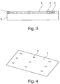
- Fig. 3 shows a tool 6 in a schematic representation, which defines a contour of the component 1 to be glued. It is straight here, but it can also be curved or shaped differently.
- the tool 6 can, for example, be molded from a ground damage in a component of an aircraft have been.
- the component 1 to be glued is placed on the tool 6, for example in the form of a laminate with the flat structure 2, for example in the form of a peel-off film and the passages 3, and thus transmits its contour.
- the hardenable liquid 4 is poured in and solidifies in the passages 3.
- the component 1 to be bonded with the flat structure 2 and the hardened liquid 4 is removed from the tool 6, the flat structure 2 is pulled off and the component 1 with the liquid 4 thus hardened formed spacers 5 (see Fig. 4 ) stuck in place of the ground damage in the aircraft component.
- the sheet 2 with the curable or already hardened liquid 4 can preferably also remain on the first component 1 until immediately before the bonding to the second component or until immediately before a surface treatment, and thus e.g. act as a protective layer.
- Fig. 4 shows a three-dimensional view of the component 1 to be glued with spacers 5 in a schematic representation.
- the spacers 5 here have the shape of knobs and are circular and evenly distributed in rows over the component.
- the knobs can ensure a predetermined adhesive gap thickness or minimum adhesive gap thickness.
Landscapes
- Engineering & Computer Science (AREA)
- Mechanical Engineering (AREA)
- General Engineering & Computer Science (AREA)
- Chemical & Material Sciences (AREA)
- Organic Chemistry (AREA)
- Lining Or Joining Of Plastics Or The Like (AREA)
- Moulding By Coating Moulds (AREA)
- Lining And Supports For Tunnels (AREA)
- Treatments For Attaching Organic Compounds To Fibrous Goods (AREA)
- Knitting Of Fabric (AREA)
Description
- Die vorliegende Erfindung betrifft ein Verfahren zum Bereitstellen von Abstandshaltern auf einem zu verklebenden Bauteil und ein entsprechendes Bauteil. Die Abstandshalter oder Distanzelemente legen eine vorbestimmte Klebespaltdicke fest, die auch bei lokalen Überpressungen nicht unterschritten werden kann.
-
DE 197 37 966 A1 offenbart eine Klebeverbindung zwischen zwei Bauteilen mit einem aushärtbaren Kunststoff. Eines der Bauteile weist angeformte bzw. angeschraubte Distanzelemente auf, welche im Bereich einer Klebefläche am anderen Bauteil zur Anlage kommen und dabei einen Klebespalt mit einer vorbestimmten Klebespaltdicke ausbilden. Die Distanzelemente sind als Noppen vorgesehen, die im Vergleich zur Klebefläche punktförmig ausgebildet und im Klebespalt verteilt angeordnet sind. - Aufgabe der vorliegenden Erfindung ist das zur Verfügung stellen eines verbesserten Verfahrens zum Bereitstellen von Abstandshaltern auf einem zu verklebenden Bauteil, welches insbesondere die Abstandshalter mit weniger Aufwand bereitstellt.
- Diese Aufgabe wird durch ein Verfahren zum Bereitstellen von Abstandshaltern auf einem zu verklebenden Bauteil und ein solches Bauteil gemäß den Merkmalen der unabhängigen Ansprüche gelöst. Vorteilhafte Ausführungsformen und Weiterbildungen sind den Unteransprüchen und der nachfolgenden Beschreibung zu entnehmen.
- Das Verfahren zum Bereitstellen von Abstandshaltern auf einem zu verklebenden Bauteil umfasst die folgenden Schritte:
- Ein Flächengebilde wird auf das zu verklebende Bauteil aufgelegt. Das Flächengebilde weist Durchlässe auf.
- Eine aushärtbare Flüssigkeit wird in die Durchlässe des Flächengebildes eingebracht, sodass die Flüssigkeit nach einem Aushärten und einem Abziehen des Flächengebildes Abstandshalter auf dem zu verklebenden Bauteil bildet. Die Abstandshalter stellen bei einer Verklebung des Bauteils eine vorbestimmte Klebespaltdicke sicher.
- In anderen Worten und als beispielhafte Ausführungsform: Es sind zwei Bauteile zu verkleben, wovon mindestens eines aus Faserverbundwerkstoff besteht, und wobei ein vorbestimmter Klebespalt eingehalten werden soll. Vor dem Aushärten der beiden Bauteile wird auf zumindest eines der Bauteile ein Flächengebilde aufgebracht. Das Flächengebilde kann eine Folie sein und weist Durchlässe bzw. Löcher auf. Es wird eine aushärtbare Flüssigkeit auf das Flächengebilde mit den Durchlässen aufgebracht und die Flüssigkeit dringt in die Durchlässe des Flächengebildes ein. Diese aushärtbare Flüssigkeit kann z.B. aus einem bereits mit Harz getränkten Prepreg kommen oder durch ein Infusionsverfahren eingebracht werden. Nach einem Aushärten der Flüssigkeit und einem Abziehen des Flächengebildes bleiben auf dem Bauteil Strukturen aus ausgehärteter Flüssigkeit übrig. Diese erhabenen Strukturen oder Stifte dienen bei der Verklebung des Bauteils mit einem anderen Bauteil als Abstandshalter und können so eine vorbestimmte Klebespaltdicke sicherstellen. Nach dem Abziehen des Flächengebildes kann ein Klebstoff aufgebracht, und die beiden Bauteile miteinander verklebt werden.
- Das Verfahren gemäß der Erfindung kann bei der Verklebung von Bauteilen in der Fertigung, der Montage, der Wartung, der Reparatur usw. eingesetzt werden und verringert den Aufwand zur Bereitstellung von Abstandshaltern beträchtlich. Es stellt sicher, dass eine vorbestimmte Klebeschichtdicke erreicht, oder eine Mindestklebeschichtdicke nicht unterschritten wird. Es ist die Verwendung von konventionellen, nicht modifizierten Werkzeugen möglich. Es sind keine zusätzlichen Hilfsstoffe oder Distanzelemente in der Verklebung nötig. Es sind auch keine weiteren Werkzeuge und entsprechende Rüstzeiten notwendig.
- Das Verfahren gemäß der Erfindung ist insbesondere bei der Verwendung von pastösen Klebstoffen geeignet, da die extrem aufwändige Positionierung von konventionellen Abstandshaltern in pastösen Klebstoffen unnötig wird. Weiterhin ist das Verfahren gemäß der Erfindung sehr gut kompatibel mit modernen Oberflächen(vor)behandungsmethoden und Fertigungsverfahren, wie z.B. Plasma- oder Laserverfahren.
- Vorzugsweise kann das Flächengebilde mit der aushärtbaren oder bereits ausgehärteten Flüssigkeit bis unmittelbar vor der Verklebung mit dem zweiten Bauteil oder bis unmittelbar vor einer Oberflächenbehandlung auf dem ersten Bauteil verbleiben und so z.B. als Schutzfolie wirken.
- Vorzugsweise kann auch eine Klebespaltmindestdicke sichergestellt werden.
- Die Bauteile sind vorzugsweise aus Faserverbundwerkstoffen, Kunststoff oder ähnlichem.
- Das Flächengebilde kann eine Folie, ein Gewebe, ein Gestrick, eine Gewirk oder ähnliches sein. Das Flächengebilde kann Fasern, bevorzugt Polymerfasern, und weiter bevorzugt Fluorpolymerfasern umfassen.
- Die aushärtbare Flüssigkeit kann ein Epoxidharz, ein Kunststoff oder ähnliches sein. Die aushärtbare Flüssigkeit kann auch ein aushärtbarer Schaum sein.
- Das Aushärten kann durch die Zeit, durch Temperatur, Gaseinwirkung oder ähnliches geschehen.
- Die Abstandshalter können eine erhabene Struktur auf dem zu verklebenden Bauteil bilden. Die Durchlässe des Flächengebildes, die die Abstandshalter bilden werden, können bezüglich ihrer Form, Höhe, Größe, Dichte und/oder Verteilung bzgl. des Flächengebildes variabel sein. Die Querschnitte der Durchlässe können z.B. kreisförmig, kreuzförmig, oval, eckig, linienförmig und/oder sternförmig sein. Die Grund- und Stirnflächen der Durchlässe bzw. der Abstandshalter, die an den beiden zu verklebenden Bauteilen angrenzen werden, können dieselbe oder eine andere Grundfläche aufweisen. Das heißt, der Durchmesser oder Querschnitt eines Durchlasses bzw. Abstandshalters kann sich über seine Höhe verjüngen oder verbreitern. Der Durchlass bzw. Abstandshalter kann also eine Kegel-, Kegelstumpf-, Doppelkegel-, Pyramiden-, Schrauben- oder Sanduhrform oder ähnliches aufweisen. Die Form des Abstandshalters wird durch die Form des Durchlasses im Flächengebilde definiert. Die Durchlässe können über die Fläche des Flächengebildes gleichmäßig oder graduell verteilt sein. Auch ihre Form, Höhe, Größe, Dichte und/oder Verteilung kann über die Fläche des Flächengebildes hinweg gleichmäßig sein oder variieren. Das heißt, in einem Teil des Flächengebildes können anders geformte, höhere, größere, anders verteilte oder mehr Durchlässe vorhanden sein, als in einem anderen Teil des Flächengebildes.
- Die Durchlässe können während der Herstellung des Flächengebildes in das Flächengebilde eingewirkt werden, d.h. während des Webens, Strickens, Wirkens usw. freigelassen bzw. umwebt, umstrickt oder umwirkt werden. Die Durchlässe können auch eingestanzt, eingebohrt, eingedrückt, z.B. durch einen Laser eingeschossen oder ähnliches werden oder schlicht bei der Herstellung des Flächengebildes freigelassen werden.
- Die vorliegende Erfindung betrifft weiterhin ein Bauteil mit einem solchen Flächengebilde und Durchlässen.
- Weitere Merkmale, Vorteile und Anwendungsmöglichkeiten der vorliegenden Erfindung ergeben sich aus der nachfolgenden Beschreibung der Ausführungsbeispiele und den Figuren. Dabei bilden alle beschriebenen und/oder bildlich dargestellten Merkmale für sich und in beliebiger Kombination den Gegenstand der Erfindung auch unabhängig von ihrer Zusammensetzung in den einzelnen Ansprüchen oder deren Rückbezügen. In den Figuren stehen gleiche Bezugszeichen für gleiche oder ähnliche Objekte.
- Nachfolgend wird anhand der beigefügten Zeichnungen näher auf Ausführungsbeispiele der Erfindung eingegangen.
- Fig. 1
- zeigt eine Draufsicht auf ein Flächengebilde in der Form einer Folie in einer schematischen Darstellung.
- Fig. 2
- zeigt einen Querschnitt durch ein Bauteil mit aufgelegtem Flächengebilde in einer schematischen Darstellung.
- Fig. 3
- zeigt ein Werkzeug und ein Bauteil mit Flächengebilde in einer schematischen Darstellung.
- Fig. 4
- zeigt eine räumliche Ansicht des zu verklebende Bauteils mit Abstandshaltern in einer schematischen Darstellung.
-
Fig. 1 zeigt eine Draufsicht auf ein Flächengebilde 2 in der Form einer Folie in einer schematischen Darstellung. Beispielhaft sind verschiedene Formen von Durchgängen 3 bzw. Löchern gezeigt, z.B. kreisförmig, oval, kreuzförmig, sternförmig oder linienförmig. Die Durchgänge 3 weisen unterschiedliche Größen auf. - Das Flächengebilde 2 mit den Durchgängen 3 wird auf ein zu verklebendes Bauteil 1 (siehe
Fig. 2 ) aufgelegt. Die Durchgänge 3 werden mit einer aushärtbaren Flüssigkeit 4 ausgegossen und das Flächengebilde 2 wieder von dem Bauteil 1 abgezogen. Die in den Durchgängen 3 erstarrte Flüssigkeit 4 bleibt alleine auf dem Bauteil 1 in Form von z.B. Stiften stehen. Diese Stifte bilden bei einer Verklebung des Bauteils 1 mit einem weiteren Bauteil Abstandshalter 5 (sieheFig. 4 ), die eine vorbestimmte Klebespaltdicke sicherstellen oder das Unterschreiten einer vorbestimmten Klebespaltdicke auch bei lokalen Überpressungen verhindern. - Die Durchgänge 3 bzw. die späteren Abstandshalter 5 können bezüglich ihrer Form, Höhe, Größe, Dichte und/oder Verteilung einheitlich oder unterschiedlich über der Fläche des Flächengebildes 2 sein. Das heißt, es können auf demselben Flächengebilde 2 unterschiedliche Formen und Größen von Durchgängen 3 angeordnet sein. Auch ihre Dichte bzw. Verteilung kann über die Fläche des Flächengebildes 2 hinweg variieren oder gleichmäßig sein.
- Die Dicke des Flächengebildes 2 kann zwischen 0,001 und 10 mm liegen, vorzugsweise zwischen 0,01 und 1 mm, weiter bevorzugt zwischen 0,1 und 0,3 mm.
- Das Flächengebilde 2 kann eine Folie, ein Gewebe, ein Gestrick, eine Gewirk oder ähnliches sein. Das Flächengebilde 2 kann Fasern, bevorzugt Polymerfasern, und weiter bevorzugt Fluorpolymerfasern umfassen.
- Der Durchmesser bzw. Querschnitt eines Durchgangs 3 bzw. Lochs kann zwischen 0,1 und 5 mm liegen, vorzugsweise zwischen 0,2 und 3 mm, weiter bevorzugt zwischen 1 und 2 mm.
- Die aushärtbare Flüssigkeit kann ein Epoxidharz, ein Kunststoff oder ähnliches sein.
- Die zu verklebenden Bauteile 1 sind vorzugsweise aus Faserverbund- oder Kunststoffwerkstoffen oder ähnlichem.
-
Fig. 2 zeigt einen Querschnitt durch das Bauteil 1 mit aufgelegtem Flächengebilde 2 in einer schematischen Darstellung. Das Flächengebilde 2 weist Durchlässe 3 bzw. Löcher auf. Die Durchlässe 3 sind ungleichmäßig über das Flächengebilde 2 verteilt. Die Durchlässe 3 sind unterschiedlich groß bzw. breit. - Die Durchgänge 3 werden mit einer aushärtbaren Flüssigkeit 4 ausgegossen, die meist bündig mit dem Flächengebilde 2 abschließt, hier aber (auch aus illustrativen Zwecken) über das Flächengebilde 2 hinausgeht und es bedeckt.
- Die Durchlässe 3 können während der Herstellung des Flächengebildes 2 in das Flächengebilde 2 eingewirkt werden, d.h. während des Webens, Strickens, Wirkens usw. freigelassen bzw. umwebt, umstrickt oder umwirkt werden. Die Durchlässe 3 können auch eingestanzt, eingebohrt, eingedrückt, z.B. durch einen Laser eingeschossen oder ähnliches werden oder schlicht bei der Herstellung des Flächengebildes 2 freigelassen werden.
- Wird das Bauteil 1 mit einem weiteren Bauteil (nicht gezeigt) verklebt, so kann auch das weitere Bauteil auf dieselbe Weise mit Abstandshaltern 5 versehen worden sein. Die Abstandshalter 5 können beim Verkleben miteinander fluchten oder zueinander versetzt sein.
- Das Verfahren gemäß der Erfindung kann bei der Verklebung von Bauteilen 1 in der Fertigung, der Montage, der Wartung, der Reparatur usw. eingesetzt werden.
-
Fig. 3 zeigt ein Werkzeug 6 in einer schematischen Darstellung, welches eine Kontur des zu verklebenden Bauteils 1 festlegt. Hier ist es gerade, es kann aber auch geschwungen oder anders geformt sein. Das Werkzeug 6 kann z.B. von einem ausgeschliffenen Schaden in einer Komponente eines Flugzeugs abgeformt worden sein. Auf das Werkzeug 6 wird das zu verklebende Bauteil 1 z.B. in der Form eines Laminats mit dem Flächengebilde 2 z.B. in der Form einer Abziehfolie und den Durchlässen 3 aufgelegt und überträgt so seine Kontur. Die aushärtbare Flüssigkeit 4 wird eingegossen und erstarrt in den Durchlässen 3. Das zu verklebende Bauteil 1 mit dem Flächengebilde 2 und der ausgehärteten Flüssigkeit 4 wird von dem Werkzeug 6 abgenommen, das Flächengebilde 2 abgezogen und das Bauteil 1 mit den so aus der ausgehärteten Flüssigkeit 4 gebildeten Abstandshaltern 5 (sieheFig. 4 ) an die Stelle des ausgeschliffenen Schadens in der Flugzeugkomponente geklebt. - Vorzugsweise kann das Flächengebilde 2 mit der aushärtbaren oder bereits ausgehärteten Flüssigkeit 4 auch bis unmittelbar vor der Verklebung mit dem zweiten Bauteil oder bis unmittelbar vor einer Oberflächenbehandlung auf dem ersten Bauteil 1 verbleiben und so z.B. als Schutzschicht wirken.
-
Fig. 4 zeigt eine räumliche Ansicht des zu verklebende Bauteils 1 mit Abstandshaltern 5 in einer schematischen Darstellung. Die Abstandshalter 5 haben hier die Form von Noppen und sind kreisförmig und gleichmäßig in Reihen über das Bauteil verteilt. Die Noppen können eine vorbestimmte Klebespaltdicke oder Klebespaltmindestdicke sicherstellen. - Ergänzend ist darauf hinzuweisen, dass "umfassend" keine anderen Elemente oder Schritte ausschließt und "eine" oder "ein" keine Vielzahl ausschließt. Ferner sei darauf hingewiesen, dass Merkmale oder Schritte, die mit Verweis auf eines der obigen Ausführungsbeispiele beschrieben worden sind, auch in Kombination mit anderen Merkmalen oder Schritten anderer oben beschriebener Ausführungsbeispiele verwendet werden können. Bezugszeichen in den Ansprüchen sind nicht als Einschränkung anzusehen.
Claims (9)
- Ein Verfahren zum Bereitstellen von Abstandshaltern (5) auf einem zu verklebenden Bauteil (1), umfassend die folgenden Schritte:- Auflegen eines Flächengebildes (2) auf das zu verklebende Bauteil (1), wobei das Flächengebilde (2) Durchlässe (3) aufweist, und- Einbringen einer aushärtbaren Flüssigkeit (4) in die Durchlässe (3) des Flächengebildes (2), sodass die Flüssigkeit (4) nach einem Aushärten und einem Abziehen des Flächengebildes (2) Abstandshalter (5) auf dem zu verklebenden Bauteil (1) bildet, die bei einer Verklebung des Bauteils (1) eine vorbestimmte Klebespaltdicke sicherstellen.
- Verfahren nach Anspruch 1, weiter umfassend ein Abziehen des Flächengebildes (2).
- Verfahren nach Anspruch 1, wobei das Flächengebilde (2) eine Folie, ein Gewebe, ein Gestrick, eine Gewirk oder ähnliches ist.
- Verfahren nach einem der vorherigen Ansprüche, wobei die Abstandshalter (5) eine Klebespaltmindestdicke sicherstellen.
- Verfahren nach einem der vorherigen Ansprüche, wobei die Abstandshalter (5) eine erhabene Struktur auf dem zu verklebenden Bauteil (1) bilden.
- Verfahren nach einem der vorherigen Ansprüche, wobei die Durchlässe (3) im Flächengebilde (2) bezüglich ihrer Form, Höhe, Größe und/oder Verteilung variabel sind.
- Verfahren nach einem der vorherigen Ansprüche, wobei die Durchlässe (3) im Querschnitt kreisförmig, oval, kreuzförmig, eckig, linienförmig und/oder sternförmig sind.
- Verfahren nach einem der vorherigen Ansprüche, wobei das Flächengebilde (2) Fasern, bevorzugt Polymerfasern, und weiter bevorzugt Fluorpolymerfasern umfasst.
- Verfahren nach einem der vorherigen Ansprüche, wobei die Durchlässe (3) während der Herstellung des Flächengebildes (2) in das Flächengebilde (2) eingewirkt oder während eines Stanzprozess in das Flächengebilde (2) eingebracht werden.
Applications Claiming Priority (1)
| Application Number | Priority Date | Filing Date | Title |
|---|---|---|---|
| DE102014005146.3A DE102014005146A1 (de) | 2014-04-05 | 2014-04-05 | Verfahren zum Bereitstellen von Abstandshaltern |
Publications (2)
| Publication Number | Publication Date |
|---|---|
| EP2926990A1 EP2926990A1 (de) | 2015-10-07 |
| EP2926990B1 true EP2926990B1 (de) | 2020-02-26 |
Family
ID=52987797
Family Applications (1)
| Application Number | Title | Priority Date | Filing Date |
|---|---|---|---|
| EP15000946.2A Active EP2926990B1 (de) | 2014-04-05 | 2015-04-01 | Verfahren zum bereitstellen von abstandshaltern |
Country Status (6)
| Country | Link |
|---|---|
| US (1) | US10166724B2 (de) |
| EP (1) | EP2926990B1 (de) |
| BR (1) | BR102015007019A2 (de) |
| DE (1) | DE102014005146A1 (de) |
| ES (1) | ES2788859T3 (de) |
| RU (1) | RU2634128C2 (de) |
Families Citing this family (3)
| Publication number | Priority date | Publication date | Assignee | Title |
|---|---|---|---|---|
| JP6109271B2 (ja) * | 2015-02-06 | 2017-04-05 | 株式会社神戸製鋼所 | 接合構造体、及び接合構造体の製造方法 |
| DE102015225467B4 (de) | 2015-12-16 | 2019-12-19 | Airbus Defence and Space GmbH | Beschichtetes Verbundbauteil und Verfahren zum Herstellen eines beschichteten Verbundbauteils |
| DE102019132344A1 (de) * | 2019-11-28 | 2021-06-02 | Lufthansa Technik Aktiengesellschaft | Vorrichtung für das Anbringen von aerodynamisch funktionalen Folien und deren Verwendung |
Family Cites Families (6)
| Publication number | Priority date | Publication date | Assignee | Title |
|---|---|---|---|---|
| FR2688345B1 (fr) * | 1988-11-18 | 1994-09-02 | Thomson Csf | Structure absorbant les ondes electromagnetiques. |
| DE19737966A1 (de) | 1997-08-30 | 1998-08-06 | Daimler Benz Ag | Klebverbindung zwischen zwei Bauteilen |
| US6692600B2 (en) * | 2001-09-14 | 2004-02-17 | Guardian Industries Corp. | VIG evacuation with plasma excitation |
| DE10338967B4 (de) * | 2003-08-25 | 2007-02-22 | Technische Universität Braunschweig Carolo-Wilhelmina | Verfahren zum Kleben von Mikrobauteilen auf ein Substrat |
| DE102006017147A1 (de) * | 2006-04-12 | 2007-10-25 | Bayerische Motoren Werke Ag | Dachstruktur für ein Kraftfahrzeug |
| DE102011079410B4 (de) * | 2011-07-19 | 2013-08-29 | Siemens Aktiengesellschaft | Verfahren zur Fixierung zumindest eines Bauteils auf einem Träger |
-
2014
- 2014-04-05 DE DE102014005146.3A patent/DE102014005146A1/de not_active Ceased
-
2015
- 2015-03-30 BR BR102015007019A patent/BR102015007019A2/pt not_active IP Right Cessation
- 2015-04-01 ES ES15000946T patent/ES2788859T3/es active Active
- 2015-04-01 EP EP15000946.2A patent/EP2926990B1/de active Active
- 2015-04-03 US US14/678,189 patent/US10166724B2/en active Active
- 2015-04-03 RU RU2015112170A patent/RU2634128C2/ru not_active IP Right Cessation
Non-Patent Citations (1)
| Title |
|---|
| None * |
Also Published As
| Publication number | Publication date |
|---|---|
| BR102015007019A2 (pt) | 2015-12-08 |
| US10166724B2 (en) | 2019-01-01 |
| RU2015112170A (ru) | 2016-10-20 |
| DE102014005146A1 (de) | 2015-10-08 |
| US20150283757A1 (en) | 2015-10-08 |
| ES2788859T3 (es) | 2020-10-23 |
| EP2926990A1 (de) | 2015-10-07 |
| RU2634128C2 (ru) | 2017-10-24 |
Similar Documents
| Publication | Publication Date | Title |
|---|---|---|
| DE102005034393B4 (de) | Verfahren zur Herstellung von ein- oder mehrschichtigen Faservorformlingen im TFP-Verfahren | |
| DE69508525T2 (de) | Verfahren zur Herstellung schichtartiger Verbundwerkstoffplatten und so hergestellte Platten | |
| EP3069858B1 (de) | Verfahren und Vorrichtung zur Herstellung eines Windenergieanlagenbauteils aus einem Faserverbundwerkstoff | |
| EP3023236B1 (de) | Verfahren zur herstellung von faserverbundteilen und ein faserverbundteil und vorprodukt | |
| EP4010178B1 (de) | Verfahren zum reparieren eines faserverbundbauteils | |
| DE102007003273A1 (de) | Lokalisierte Bearbeitung von verstärkten Schaumwerkstoffen sowie Kernverbundbauteil | |
| WO2014095865A1 (de) | Variable formvorrichtung zur herstellung einer halbschale für ein rotorblatt für eine windenergieanlage | |
| EP2926990A1 (de) | Verfahren zum bereitstellen von abstandshaltern | |
| DE102012211765A1 (de) | Kernschicht für ein Sandwichverbundbauteil, Sandwichverbundbauteil und Verfahren zur Herstellung eines Sandwichverbundbauteils | |
| EP3682121B1 (de) | Verfahren zur herstellung eines sandwichelements und sandwichelement | |
| DE102012001317A1 (de) | Faserverbundkunststoff-Bauteil und Herstellungsverfahren dafür | |
| DE102012013538B4 (de) | Verfahren zur Herstellung von Sandwichelementen | |
| DE102012223871B4 (de) | Verfahren für die Vorbereitung eines Halbzeugs aus Fasermaterial auf ein Nasspressverfahren sowie Vorbereitungsvorrichtung für die Vorbereitung eines Halbzeugs aus Fasermaterial auf ein Nasspressverfahren | |
| DE102016214187B4 (de) | Verfahren zum Herstellen eines dreidimensionalen, vielschichtigen Faserverbundbauteils und ein mit den Verfahren hergestelltes Bauteil | |
| DE102015201348A1 (de) | Verfahren zum Ausbilden eines Funktionsabschnitts an einem Faserverbundbauteil | |
| DE2721696B2 (de) | Verfahren zum Ausbessern schadhafter Platten und Vorrichtung zur Durchführung des Verfahrens | |
| EP1235284B1 (de) | Piezokeramische Platte und Verfahren zum Herstellen derselben | |
| AT519620B1 (de) | Schaumstoffplatte | |
| DE2940582C2 (de) | Verfahren und Vorrichtung zum Beschichten von Elementen zum Sortieren, Klassieren und/oder Trennen von Gütern | |
| WO2020109130A1 (de) | Verfahren zum bearbeiten von faserverbundbauteilen und faserverbundbauteil | |
| EP3727814B1 (de) | Kratzfeste leichtbauplatte | |
| DE102015204426A1 (de) | Sandwich-Bauteil oder Sandwich-Halbzeug | |
| DE102016202744A1 (de) | Verfahren zur Herstellung einer Baugruppe aus einem Trägerteil und einem Gewindeelement sowie Baugruppe aus einem Trägerteil und einem Gewindeelement | |
| DE102018220634A1 (de) | Verfahren zum Herstellen einer Feder-Baugruppe, Feder-Baugruppe und Feder einer Feder-Baugruppe | |
| DE102018220636A1 (de) | Verfahren zum Herstellen einer Feder-Baugruppe, Feder-Baugruppe und Feder einer Feder-Baugruppe |
Legal Events
| Date | Code | Title | Description |
|---|---|---|---|
| PUAI | Public reference made under article 153(3) epc to a published international application that has entered the european phase |
Free format text: ORIGINAL CODE: 0009012 |
|
| AK | Designated contracting states |
Kind code of ref document: A1 Designated state(s): AL AT BE BG CH CY CZ DE DK EE ES FI FR GB GR HR HU IE IS IT LI LT LU LV MC MK MT NL NO PL PT RO RS SE SI SK SM TR |
|
| AX | Request for extension of the european patent |
Extension state: BA ME |
|
| 17P | Request for examination filed |
Effective date: 20160301 |
|
| RBV | Designated contracting states (corrected) |
Designated state(s): AL AT BE BG CH CY CZ DE DK EE ES FI FR GB GR HR HU IE IS IT LI LT LU LV MC MK MT NL NO PL PT RO RS SE SI SK SM TR |
|
| STAA | Information on the status of an ep patent application or granted ep patent |
Free format text: STATUS: EXAMINATION IS IN PROGRESS |
|
| 17Q | First examination report despatched |
Effective date: 20181109 |
|
| GRAP | Despatch of communication of intention to grant a patent |
Free format text: ORIGINAL CODE: EPIDOSNIGR1 |
|
| STAA | Information on the status of an ep patent application or granted ep patent |
Free format text: STATUS: GRANT OF PATENT IS INTENDED |
|
| INTG | Intention to grant announced |
Effective date: 20190923 |
|
| GRAS | Grant fee paid |
Free format text: ORIGINAL CODE: EPIDOSNIGR3 |
|
| GRAA | (expected) grant |
Free format text: ORIGINAL CODE: 0009210 |
|
| STAA | Information on the status of an ep patent application or granted ep patent |
Free format text: STATUS: THE PATENT HAS BEEN GRANTED |
|
| AK | Designated contracting states |
Kind code of ref document: B1 Designated state(s): AL AT BE BG CH CY CZ DE DK EE ES FI FR GB GR HR HU IE IS IT LI LT LU LV MC MK MT NL NO PL PT RO RS SE SI SK SM TR |
|
| REG | Reference to a national code |
Ref country code: GB Ref legal event code: FG4D Free format text: NOT ENGLISH |
|
| REG | Reference to a national code |
Ref country code: CH Ref legal event code: EP |
|
| REG | Reference to a national code |
Ref country code: AT Ref legal event code: REF Ref document number: 1237133 Country of ref document: AT Kind code of ref document: T Effective date: 20200315 |
|
| REG | Reference to a national code |
Ref country code: IE Ref legal event code: FG4D Free format text: LANGUAGE OF EP DOCUMENT: GERMAN |
|
| REG | Reference to a national code |
Ref country code: DE Ref legal event code: R096 Ref document number: 502015011817 Country of ref document: DE |
|
| PG25 | Lapsed in a contracting state [announced via postgrant information from national office to epo] |
Ref country code: NO Free format text: LAPSE BECAUSE OF FAILURE TO SUBMIT A TRANSLATION OF THE DESCRIPTION OR TO PAY THE FEE WITHIN THE PRESCRIBED TIME-LIMIT Effective date: 20200526 Ref country code: RS Free format text: LAPSE BECAUSE OF FAILURE TO SUBMIT A TRANSLATION OF THE DESCRIPTION OR TO PAY THE FEE WITHIN THE PRESCRIBED TIME-LIMIT Effective date: 20200226 Ref country code: FI Free format text: LAPSE BECAUSE OF FAILURE TO SUBMIT A TRANSLATION OF THE DESCRIPTION OR TO PAY THE FEE WITHIN THE PRESCRIBED TIME-LIMIT Effective date: 20200226 |
|
| REG | Reference to a national code |
Ref country code: NL Ref legal event code: MP Effective date: 20200226 |
|
| REG | Reference to a national code |
Ref country code: LT Ref legal event code: MG4D |
|
| PG25 | Lapsed in a contracting state [announced via postgrant information from national office to epo] |
Ref country code: BG Free format text: LAPSE BECAUSE OF FAILURE TO SUBMIT A TRANSLATION OF THE DESCRIPTION OR TO PAY THE FEE WITHIN THE PRESCRIBED TIME-LIMIT Effective date: 20200526 Ref country code: GR Free format text: LAPSE BECAUSE OF FAILURE TO SUBMIT A TRANSLATION OF THE DESCRIPTION OR TO PAY THE FEE WITHIN THE PRESCRIBED TIME-LIMIT Effective date: 20200527 Ref country code: IS Free format text: LAPSE BECAUSE OF FAILURE TO SUBMIT A TRANSLATION OF THE DESCRIPTION OR TO PAY THE FEE WITHIN THE PRESCRIBED TIME-LIMIT Effective date: 20200626 Ref country code: LV Free format text: LAPSE BECAUSE OF FAILURE TO SUBMIT A TRANSLATION OF THE DESCRIPTION OR TO PAY THE FEE WITHIN THE PRESCRIBED TIME-LIMIT Effective date: 20200226 Ref country code: SE Free format text: LAPSE BECAUSE OF FAILURE TO SUBMIT A TRANSLATION OF THE DESCRIPTION OR TO PAY THE FEE WITHIN THE PRESCRIBED TIME-LIMIT Effective date: 20200226 Ref country code: HR Free format text: LAPSE BECAUSE OF FAILURE TO SUBMIT A TRANSLATION OF THE DESCRIPTION OR TO PAY THE FEE WITHIN THE PRESCRIBED TIME-LIMIT Effective date: 20200226 |
|
| PG25 | Lapsed in a contracting state [announced via postgrant information from national office to epo] |
Ref country code: NL Free format text: LAPSE BECAUSE OF FAILURE TO SUBMIT A TRANSLATION OF THE DESCRIPTION OR TO PAY THE FEE WITHIN THE PRESCRIBED TIME-LIMIT Effective date: 20200226 |
|
| REG | Reference to a national code |
Ref country code: ES Ref legal event code: FG2A Ref document number: 2788859 Country of ref document: ES Kind code of ref document: T3 Effective date: 20201023 |
|
| PG25 | Lapsed in a contracting state [announced via postgrant information from national office to epo] |
Ref country code: PT Free format text: LAPSE BECAUSE OF FAILURE TO SUBMIT A TRANSLATION OF THE DESCRIPTION OR TO PAY THE FEE WITHIN THE PRESCRIBED TIME-LIMIT Effective date: 20200719 Ref country code: SK Free format text: LAPSE BECAUSE OF FAILURE TO SUBMIT A TRANSLATION OF THE DESCRIPTION OR TO PAY THE FEE WITHIN THE PRESCRIBED TIME-LIMIT Effective date: 20200226 Ref country code: SM Free format text: LAPSE BECAUSE OF FAILURE TO SUBMIT A TRANSLATION OF THE DESCRIPTION OR TO PAY THE FEE WITHIN THE PRESCRIBED TIME-LIMIT Effective date: 20200226 Ref country code: LT Free format text: LAPSE BECAUSE OF FAILURE TO SUBMIT A TRANSLATION OF THE DESCRIPTION OR TO PAY THE FEE WITHIN THE PRESCRIBED TIME-LIMIT Effective date: 20200226 Ref country code: DK Free format text: LAPSE BECAUSE OF FAILURE TO SUBMIT A TRANSLATION OF THE DESCRIPTION OR TO PAY THE FEE WITHIN THE PRESCRIBED TIME-LIMIT Effective date: 20200226 Ref country code: CZ Free format text: LAPSE BECAUSE OF FAILURE TO SUBMIT A TRANSLATION OF THE DESCRIPTION OR TO PAY THE FEE WITHIN THE PRESCRIBED TIME-LIMIT Effective date: 20200226 Ref country code: RO Free format text: LAPSE BECAUSE OF FAILURE TO SUBMIT A TRANSLATION OF THE DESCRIPTION OR TO PAY THE FEE WITHIN THE PRESCRIBED TIME-LIMIT Effective date: 20200226 Ref country code: EE Free format text: LAPSE BECAUSE OF FAILURE TO SUBMIT A TRANSLATION OF THE DESCRIPTION OR TO PAY THE FEE WITHIN THE PRESCRIBED TIME-LIMIT Effective date: 20200226 |
|
| REG | Reference to a national code |
Ref country code: DE Ref legal event code: R097 Ref document number: 502015011817 Country of ref document: DE |
|
| PG25 | Lapsed in a contracting state [announced via postgrant information from national office to epo] |
Ref country code: MC Free format text: LAPSE BECAUSE OF FAILURE TO SUBMIT A TRANSLATION OF THE DESCRIPTION OR TO PAY THE FEE WITHIN THE PRESCRIBED TIME-LIMIT Effective date: 20200226 |
|
| REG | Reference to a national code |
Ref country code: CH Ref legal event code: PL |
|
| PLBE | No opposition filed within time limit |
Free format text: ORIGINAL CODE: 0009261 |
|
| STAA | Information on the status of an ep patent application or granted ep patent |
Free format text: STATUS: NO OPPOSITION FILED WITHIN TIME LIMIT |
|
| PG25 | Lapsed in a contracting state [announced via postgrant information from national office to epo] |
Ref country code: LU Free format text: LAPSE BECAUSE OF NON-PAYMENT OF DUE FEES Effective date: 20200401 Ref country code: CH Free format text: LAPSE BECAUSE OF NON-PAYMENT OF DUE FEES Effective date: 20200430 Ref country code: LI Free format text: LAPSE BECAUSE OF NON-PAYMENT OF DUE FEES Effective date: 20200430 |
|
| 26N | No opposition filed |
Effective date: 20201127 |
|
| REG | Reference to a national code |
Ref country code: BE Ref legal event code: MM Effective date: 20200430 |
|
| PG25 | Lapsed in a contracting state [announced via postgrant information from national office to epo] |
Ref country code: PL Free format text: LAPSE BECAUSE OF FAILURE TO SUBMIT A TRANSLATION OF THE DESCRIPTION OR TO PAY THE FEE WITHIN THE PRESCRIBED TIME-LIMIT Effective date: 20200226 Ref country code: SI Free format text: LAPSE BECAUSE OF FAILURE TO SUBMIT A TRANSLATION OF THE DESCRIPTION OR TO PAY THE FEE WITHIN THE PRESCRIBED TIME-LIMIT Effective date: 20200226 Ref country code: BE Free format text: LAPSE BECAUSE OF NON-PAYMENT OF DUE FEES Effective date: 20200430 |
|
| PG25 | Lapsed in a contracting state [announced via postgrant information from national office to epo] |
Ref country code: IE Free format text: LAPSE BECAUSE OF NON-PAYMENT OF DUE FEES Effective date: 20200401 |
|
| REG | Reference to a national code |
Ref country code: AT Ref legal event code: MM01 Ref document number: 1237133 Country of ref document: AT Kind code of ref document: T Effective date: 20200401 |
|
| PG25 | Lapsed in a contracting state [announced via postgrant information from national office to epo] |
Ref country code: AT Free format text: LAPSE BECAUSE OF NON-PAYMENT OF DUE FEES Effective date: 20200401 |
|
| PG25 | Lapsed in a contracting state [announced via postgrant information from national office to epo] |
Ref country code: TR Free format text: LAPSE BECAUSE OF FAILURE TO SUBMIT A TRANSLATION OF THE DESCRIPTION OR TO PAY THE FEE WITHIN THE PRESCRIBED TIME-LIMIT Effective date: 20200226 Ref country code: MT Free format text: LAPSE BECAUSE OF FAILURE TO SUBMIT A TRANSLATION OF THE DESCRIPTION OR TO PAY THE FEE WITHIN THE PRESCRIBED TIME-LIMIT Effective date: 20200226 Ref country code: CY Free format text: LAPSE BECAUSE OF FAILURE TO SUBMIT A TRANSLATION OF THE DESCRIPTION OR TO PAY THE FEE WITHIN THE PRESCRIBED TIME-LIMIT Effective date: 20200226 |
|
| PG25 | Lapsed in a contracting state [announced via postgrant information from national office to epo] |
Ref country code: MK Free format text: LAPSE BECAUSE OF FAILURE TO SUBMIT A TRANSLATION OF THE DESCRIPTION OR TO PAY THE FEE WITHIN THE PRESCRIBED TIME-LIMIT Effective date: 20200226 Ref country code: AL Free format text: LAPSE BECAUSE OF FAILURE TO SUBMIT A TRANSLATION OF THE DESCRIPTION OR TO PAY THE FEE WITHIN THE PRESCRIBED TIME-LIMIT Effective date: 20200226 |
|
| PGFP | Annual fee paid to national office [announced via postgrant information from national office to epo] |
Ref country code: DE Payment date: 20250422 Year of fee payment: 11 |
|
| PGFP | Annual fee paid to national office [announced via postgrant information from national office to epo] |
Ref country code: GB Payment date: 20250423 Year of fee payment: 11 Ref country code: ES Payment date: 20250529 Year of fee payment: 11 |
|
| PGFP | Annual fee paid to national office [announced via postgrant information from national office to epo] |
Ref country code: IT Payment date: 20250424 Year of fee payment: 11 |
|
| PGFP | Annual fee paid to national office [announced via postgrant information from national office to epo] |
Ref country code: FR Payment date: 20250425 Year of fee payment: 11 |