EP2926431B1 - Security concept for integrating a battery into an inverter - Google Patents
Security concept for integrating a battery into an inverter Download PDFInfo
- Publication number
- EP2926431B1 EP2926431B1 EP12799175.0A EP12799175A EP2926431B1 EP 2926431 B1 EP2926431 B1 EP 2926431B1 EP 12799175 A EP12799175 A EP 12799175A EP 2926431 B1 EP2926431 B1 EP 2926431B1
- Authority
- EP
- European Patent Office
- Prior art keywords
- battery
- safety
- controller
- data
- monitoring unit
- Prior art date
- Legal status (The legal status is an assumption and is not a legal conclusion. Google has not performed a legal analysis and makes no representation as to the accuracy of the status listed.)
- Active
Links
Images

Classifications
-
- H—ELECTRICITY
- H02—GENERATION; CONVERSION OR DISTRIBUTION OF ELECTRIC POWER
- H02J—ELECTRIC POWER NETWORKS; CIRCUIT ARRANGEMENTS OR SYSTEMS FOR SUPPLYING OR DISTRIBUTING ELECTRIC POWER; SYSTEMS FOR STORING ELECTRIC ENERGY
- H02J13/00—Circuit arrangements for providing remote monitoring or remote control of equipment in a power distribution network
- H02J13/13—Circuit arrangements for providing remote monitoring or remote control of equipment in a power distribution network characterised by the transmission of data to equipment in the power network
- H02J13/1321—Circuit arrangements for providing remote monitoring or remote control of equipment in a power distribution network characterised by the transmission of data to equipment in the power network using a wired telecommunication network or a data transmission bus
-
- H—ELECTRICITY
- H02—GENERATION; CONVERSION OR DISTRIBUTION OF ELECTRIC POWER
- H02J—ELECTRIC POWER NETWORKS; CIRCUIT ARRANGEMENTS OR SYSTEMS FOR SUPPLYING OR DISTRIBUTING ELECTRIC POWER; SYSTEMS FOR STORING ELECTRIC ENERGY
- H02J3/00—Circuit arrangements for AC mains or AC distribution networks
- H02J3/28—Arrangements for balancing of the load in networks by storage of energy
- H02J3/32—Arrangements for balancing of the load in networks by storage of energy using batteries or super capacitors with converting means
-
- H—ELECTRICITY
- H02—GENERATION; CONVERSION OR DISTRIBUTION OF ELECTRIC POWER
- H02J—ELECTRIC POWER NETWORKS; CIRCUIT ARRANGEMENTS OR SYSTEMS FOR SUPPLYING OR DISTRIBUTING ELECTRIC POWER; SYSTEMS FOR STORING ELECTRIC ENERGY
- H02J3/00—Circuit arrangements for AC mains or AC distribution networks
- H02J3/04—Arrangements for connecting networks of the same frequency but supplied from different sources
- H02J3/06—Controlling the transfer of power between connected networks; Controlling load sharing between connected networks
-
- H—ELECTRICITY
- H02—GENERATION; CONVERSION OR DISTRIBUTION OF ELECTRIC POWER
- H02J—ELECTRIC POWER NETWORKS; CIRCUIT ARRANGEMENTS OR SYSTEMS FOR SUPPLYING OR DISTRIBUTING ELECTRIC POWER; SYSTEMS FOR STORING ELECTRIC ENERGY
- H02J3/00—Circuit arrangements for AC mains or AC distribution networks
- H02J3/38—Arrangements for feeding a single network from two or more generators or sources in parallel; Arrangements for feeding already energised networks from additional generators or sources in parallel
- H02J3/381—Dispersed generators
-
- H—ELECTRICITY
- H02—GENERATION; CONVERSION OR DISTRIBUTION OF ELECTRIC POWER
- H02J—ELECTRIC POWER NETWORKS; CIRCUIT ARRANGEMENTS OR SYSTEMS FOR SUPPLYING OR DISTRIBUTING ELECTRIC POWER; SYSTEMS FOR STORING ELECTRIC ENERGY
- H02J3/00—Circuit arrangements for AC mains or AC distribution networks
- H02J3/38—Arrangements for feeding a single network from two or more generators or sources in parallel; Arrangements for feeding already energised networks from additional generators or sources in parallel
- H02J3/46—Controlling the sharing of generated power between the generators, sources or networks
-
- H—ELECTRICITY
- H02—GENERATION; CONVERSION OR DISTRIBUTION OF ELECTRIC POWER
- H02J—ELECTRIC POWER NETWORKS; CIRCUIT ARRANGEMENTS OR SYSTEMS FOR SUPPLYING OR DISTRIBUTING ELECTRIC POWER; SYSTEMS FOR STORING ELECTRIC ENERGY
- H02J7/00—Circuit arrangements for charging or discharging batteries or for supplying loads from batteries
- H02J7/34—Parallel operation in networks using both storage and other DC sources, e.g. providing buffering
- H02J7/35—Parallel operation in networks using both storage and other DC sources, e.g. providing buffering with light sensitive cells
-
- H—ELECTRICITY
- H02—GENERATION; CONVERSION OR DISTRIBUTION OF ELECTRIC POWER
- H02J—ELECTRIC POWER NETWORKS; CIRCUIT ARRANGEMENTS OR SYSTEMS FOR SUPPLYING OR DISTRIBUTING ELECTRIC POWER; SYSTEMS FOR STORING ELECTRIC ENERGY
- H02J2101/00—Supply or distribution of decentralised, dispersed or local electric power generation
- H02J2101/20—Dispersed power generation using renewable energy sources
- H02J2101/22—Solar energy
- H02J2101/24—Photovoltaics
-
- Y—GENERAL TAGGING OF NEW TECHNOLOGICAL DEVELOPMENTS; GENERAL TAGGING OF CROSS-SECTIONAL TECHNOLOGIES SPANNING OVER SEVERAL SECTIONS OF THE IPC; TECHNICAL SUBJECTS COVERED BY FORMER USPC CROSS-REFERENCE ART COLLECTIONS [XRACs] AND DIGESTS
- Y02—TECHNOLOGIES OR APPLICATIONS FOR MITIGATION OR ADAPTATION AGAINST CLIMATE CHANGE
- Y02E—REDUCTION OF GREENHOUSE GAS [GHG] EMISSIONS, RELATED TO ENERGY GENERATION, TRANSMISSION OR DISTRIBUTION
- Y02E10/00—Energy generation through renewable energy sources
- Y02E10/50—Photovoltaic [PV] energy
- Y02E10/56—Power conversion systems, e.g. maximum power point trackers
-
- Y—GENERAL TAGGING OF NEW TECHNOLOGICAL DEVELOPMENTS; GENERAL TAGGING OF CROSS-SECTIONAL TECHNOLOGIES SPANNING OVER SEVERAL SECTIONS OF THE IPC; TECHNICAL SUBJECTS COVERED BY FORMER USPC CROSS-REFERENCE ART COLLECTIONS [XRACs] AND DIGESTS
- Y02—TECHNOLOGIES OR APPLICATIONS FOR MITIGATION OR ADAPTATION AGAINST CLIMATE CHANGE
- Y02E—REDUCTION OF GREENHOUSE GAS [GHG] EMISSIONS, RELATED TO ENERGY GENERATION, TRANSMISSION OR DISTRIBUTION
- Y02E40/00—Technologies for an efficient electrical power generation, transmission or distribution
- Y02E40/70—Smart grids as climate change mitigation technology in the energy generation sector
-
- Y—GENERAL TAGGING OF NEW TECHNOLOGICAL DEVELOPMENTS; GENERAL TAGGING OF CROSS-SECTIONAL TECHNOLOGIES SPANNING OVER SEVERAL SECTIONS OF THE IPC; TECHNICAL SUBJECTS COVERED BY FORMER USPC CROSS-REFERENCE ART COLLECTIONS [XRACs] AND DIGESTS
- Y02—TECHNOLOGIES OR APPLICATIONS FOR MITIGATION OR ADAPTATION AGAINST CLIMATE CHANGE
- Y02E—REDUCTION OF GREENHOUSE GAS [GHG] EMISSIONS, RELATED TO ENERGY GENERATION, TRANSMISSION OR DISTRIBUTION
- Y02E60/00—Enabling technologies; Technologies with a potential or indirect contribution to GHG emissions mitigation
-
- Y—GENERAL TAGGING OF NEW TECHNOLOGICAL DEVELOPMENTS; GENERAL TAGGING OF CROSS-SECTIONAL TECHNOLOGIES SPANNING OVER SEVERAL SECTIONS OF THE IPC; TECHNICAL SUBJECTS COVERED BY FORMER USPC CROSS-REFERENCE ART COLLECTIONS [XRACs] AND DIGESTS
- Y02—TECHNOLOGIES OR APPLICATIONS FOR MITIGATION OR ADAPTATION AGAINST CLIMATE CHANGE
- Y02E—REDUCTION OF GREENHOUSE GAS [GHG] EMISSIONS, RELATED TO ENERGY GENERATION, TRANSMISSION OR DISTRIBUTION
- Y02E70/00—Other energy conversion or management systems reducing GHG emissions
- Y02E70/30—Systems combining energy storage with energy generation of non-fossil origin
-
- Y—GENERAL TAGGING OF NEW TECHNOLOGICAL DEVELOPMENTS; GENERAL TAGGING OF CROSS-SECTIONAL TECHNOLOGIES SPANNING OVER SEVERAL SECTIONS OF THE IPC; TECHNICAL SUBJECTS COVERED BY FORMER USPC CROSS-REFERENCE ART COLLECTIONS [XRACs] AND DIGESTS
- Y04—INFORMATION OR COMMUNICATION TECHNOLOGIES HAVING AN IMPACT ON OTHER TECHNOLOGY AREAS
- Y04S—SYSTEMS INTEGRATING TECHNOLOGIES RELATED TO POWER NETWORK OPERATION, COMMUNICATION OR INFORMATION TECHNOLOGIES FOR IMPROVING THE ELECTRICAL POWER GENERATION, TRANSMISSION, DISTRIBUTION, MANAGEMENT OR USAGE, i.e. SMART GRIDS
- Y04S10/00—Systems supporting electrical power generation, transmission or distribution
- Y04S10/12—Monitoring or controlling equipment for energy generation units, e.g. distributed energy generation [DER] or load-side generation
- Y04S10/123—Monitoring or controlling equipment for energy generation units, e.g. distributed energy generation [DER] or load-side generation the energy generation units being or involving renewable energy sources
-
- Y—GENERAL TAGGING OF NEW TECHNOLOGICAL DEVELOPMENTS; GENERAL TAGGING OF CROSS-SECTIONAL TECHNOLOGIES SPANNING OVER SEVERAL SECTIONS OF THE IPC; TECHNICAL SUBJECTS COVERED BY FORMER USPC CROSS-REFERENCE ART COLLECTIONS [XRACs] AND DIGESTS
- Y04—INFORMATION OR COMMUNICATION TECHNOLOGIES HAVING AN IMPACT ON OTHER TECHNOLOGY AREAS
- Y04S—SYSTEMS INTEGRATING TECHNOLOGIES RELATED TO POWER NETWORK OPERATION, COMMUNICATION OR INFORMATION TECHNOLOGIES FOR IMPROVING THE ELECTRICAL POWER GENERATION, TRANSMISSION, DISTRIBUTION, MANAGEMENT OR USAGE, i.e. SMART GRIDS
- Y04S10/00—Systems supporting electrical power generation, transmission or distribution
- Y04S10/14—Energy storage units
-
- Y—GENERAL TAGGING OF NEW TECHNOLOGICAL DEVELOPMENTS; GENERAL TAGGING OF CROSS-SECTIONAL TECHNOLOGIES SPANNING OVER SEVERAL SECTIONS OF THE IPC; TECHNICAL SUBJECTS COVERED BY FORMER USPC CROSS-REFERENCE ART COLLECTIONS [XRACs] AND DIGESTS
- Y04—INFORMATION OR COMMUNICATION TECHNOLOGIES HAVING AN IMPACT ON OTHER TECHNOLOGY AREAS
- Y04S—SYSTEMS INTEGRATING TECHNOLOGIES RELATED TO POWER NETWORK OPERATION, COMMUNICATION OR INFORMATION TECHNOLOGIES FOR IMPROVING THE ELECTRICAL POWER GENERATION, TRANSMISSION, DISTRIBUTION, MANAGEMENT OR USAGE, i.e. SMART GRIDS
- Y04S40/00—Systems for electrical power generation, transmission, distribution or end-user application management characterised by the use of communication or information technologies, or communication or information technology specific aspects supporting them
- Y04S40/12—Systems for electrical power generation, transmission, distribution or end-user application management characterised by the use of communication or information technologies, or communication or information technology specific aspects supporting them characterised by data transport means between the monitoring, controlling or managing units and monitored, controlled or operated electrical equipment
- Y04S40/124—Systems for electrical power generation, transmission, distribution or end-user application management characterised by the use of communication or information technologies, or communication or information technology specific aspects supporting them characterised by data transport means between the monitoring, controlling or managing units and monitored, controlled or operated electrical equipment using wired telecommunication networks or data transmission busses
Definitions
- the present invention relates to an inverter apparatus. Especially, the present invention relates to an inverter apparatus for converting electric power from a renewable energy source, whose functionality is enhanced by the potential to store electric energy in a battery. Further, the invention relates to a method of operating such an inverter apparatus.
- SOC state of charge
- SOH state of health
- John Wynne: "Akkus auf den Zahn Kunststofft” http://www.elektroniknet.de/power/technik-know-how/batterienakkus/article/27123/0/Akkus_auf_den_Zahn_gefuchev/) discloses a photovoltaic power plant in which a photovoltaic generator is connected to a DC/DC converter.
- the DC/DC converter is connected to an AC/CD converter feeding AC electric power into a power grid.
- Battery stacks which buffer the electric energy from the photovoltaic generator are provided between two lines connecting the DC/DC converter to the AC/DC converter.
- the batteries of the battery stacks are monitored by two independent monitoring systems.
- a controller controlling both the DC/DC converter and the AC/DC converter receives a battery cell status from the monitoring systems.
- WO 2009/066880 A2 discloses a high-power, large-capacity battery module including a plurality of battery cells or unit modules connected in series to each other.
- a battery management system (BMS) is provided for protecting the battery cells from overcharge, overdischarge and overcurrent.
- the BMS detects and controls the operation of the battery module.
- the BMS switches a power switch unit to become off such that the charging and discharging operation of the battery module is interrupted. This interruption has a strong impact on any apparatus to which the battery module is connected.
- EP 2 346 138 A2 discloses a power storage apparatus, the apparatus is connected to a load, a power grid, and a power generation system.
- US 2012/0249078 A1 discloses a battery system and an energy storage system including a battery module wherein the battery management unit varies a charge limit value for stopping the charging of the at least one battery module.
- US 2012/223670 A1 discloses a power control device comprising an acquisition unit that acquires voltage information and deterioration information indicating a state of deterioration of a storage battery.
- US 2008/129249 A1 discloses a battery monitoring unit and sensors that are supplied with a common operating supply voltage, detection values from sensors are sent to a control circuit by the battery monitoring unit.
- WO 2012/034045 A1 discloses a battery monitoring system including a self-contained measurement device configured to mount to a battery cell.
- US 2012/089261 A1 discloses a grid connected power storage system wherein an integration controller changes parallel data to be transmitted to a plurality of external devices to serial bit streams and serial bit streams received from the plurality of external devices to parallel data.
- the present invention relates to an inverter apparatus comprising a DC voltage link, an input stage connected to the DC voltage link and configured to receive DC electric power from a DC power generator for loading the DC voltage link, a DC/AC converter connected to the DC voltage link and configured to feed AC electric power into a power grid, and a bidirectional connection configured to connect a battery to the DC voltage link, to load the battery out of the DC voltage link and to load the DC voltage link out of the battery.
- the inverter apparatus further comprises a controller configured to operate the DC/AC converter and the bidirectional connection. The controller is connected to an interface configured to receive present values of relevant parameters of the battery from a battery monitoring unit associated with the battery.
- the relevant parameters of the battery issued by the battery monitoring unit and received by the interface both include working data related to at least a state of charge of the battery and safety data indicating a safety state of the battery.
- the controller operates the bidirectional connection dependent on the present values of the relevant parameters of the battery in that it considers the working data in operating the bidirectional connection, and in that it is commanded by the safety data to stop further operation of the bidirectional connection and disconnect the battery by opening suitable switches of the bidirectional connection.
- the present invention relates to a method of operating an inverter apparatus which includes a DC voltage link, an input stage connected to the DC voltage link, a DC/AC converter connected to the DC voltage link, and a bidirectional connection connected to the DC voltage link.
- the method comprises connection a DC power generator to the input stage and loading the DC voltage link with DC electric power received from the DC power generator; operating the DC/AC converter to feed AC electric power into a power grid; connecting a battery to the DC voltage link via the bidirectional connection; and, dependent on present values of relevant parameters of the battery, operating the bidirectional connection to load the battery out of the DC voltage link, or to load the DC voltage link out of the battery.
- the method comprises receiving the present values of the relevant parameters of the battery from a battery monitoring unit associated with the battery, the relevant parameters of the battery received include working data related to at least a state of charge of the battery and safety data indicating a safety state of the battery; considering the working data in operating the bidirectional connection; and following commands by the safety data to stop further operation of the bidirectional connection and disconnect the battery by opening suitable switches of the bidirectional connection; and receiving the working data and the safety data via separate interface units.
- the method comprises receiving the safety data as a safety signal only indicating safety of the battery at a signal level within a predetermined safety level range and/or at a signal repetition frequency within a predetermined safety frequency range and as soon as the safety signal is no longer indicating safety of the battery, the operation of the bidirectional connection is interrupted and the battery is disconnected.
- the inverter apparatus of the present invention is configured to integrate all functions needed to safely operate a battery connected to the inverter apparatus.
- a battery module comprising the battery may be kept simple. Particularly, neither electrical nor mechanical switches are needed in the battery module.
- the different kinds of data received by the controller of the inverter apparatus according to the present invention and their different degree of relevance may be reflected by separate interface units for receiving the working data and the safety data. Further, these interface units may be different.
- the interface unit for the working data includes a CAN-bus interface unit.
- the interface unit for the safety data is configured to receive a hardware signal.
- the term "hardware signal" here refers to a signal comprising only two different states which can be processed at a hardware level without any software interpretation needed. For example these two states are two different voltage levels, or in case of a toggled hardware signal these two states may be presence versus absence of that signal.
- the safety signal may be provided by the controller and transmitted to the battery monitoring unit via the interface, and the interface may be configured to only return the safety signal at its original signal level and/or at its original signal repetition frequency to the controller, if the battery is safe.
- the safety signal as provided by the controller already qualifies as a "battery safe signal".
- the safety signal as provided by the controller is not yet indicating a safe battery.
- the safety signal will only be converted by the monitoring unit into a "battery safe signal" before it is returned to the controller, if the whole battery module functions properly.
- Such a conversion of the safety signal requires an action by the properly functioning monitoring unit and may, thus, not be provided by a short circuit.
- the conversion of the safety signal may, for example, consist of a shift of the signal level or of doubling the signal repetition frequency to get it into the safety level range and/or the safety frequency range, respectively.
- the inverter apparatus may comprise different controller units for processing the working data and the safety data.
- the controller unit for the working data may be a freely programmable controller unit
- the controller unit for the safety data may be a fixedly programmed controller unit.
- the programming of the freely programmable controller unit may be altered to adapt the controller to fulfil varying purposes in operating the bidirectional connection. Such purposes may be an optimization of the local consumption of the power produced, e.g. by a PV-generator or feeding the energy in a public grid at times when the feed-in fee is highest or supporting grid stability of the connected public grid.
- the controller unit for the working data includes a digital signal processor (DSP), and the controller unit for the safety data includes a field programmable gate array (FPGA).
- DSP digital signal processor
- FPGA field programmable gate array
- the working data provided by the battery monitoring unit may also include battery and battery monitoring unit identification data. These data may be issued by the battery monitoring unit at least during start-up of the battery monitoring unit and/or when requested by the controller of the inverter apparatus according to the present invention. Particularly, the battery and battery monitoring unit identification data may include battery monitoring unit software version information. This identification data may be processed by a predefined procedure so that the identification data is verified. In General, the battery and battery monitoring unit identification data indicate whether the controller is able to suitably operate the bidirectional connection considering the working data. Thus, the controller may only operate the bidirectional connection for loading the battery out of the DC voltage link or for loading the DC voltage link out of the battery, if the battery and battery monitoring unit identification data indicate compatibility of the battery and the battery monitoring unit with the inverter apparatus.
- the bidirectional connection comprises a bidirectional DC/DC converter operated by the controller.
- the bidirectional connection comprises an electrical cut-off switch and a mechanical cut-off switch operated by the controller.
- the mechanical cut-off switch operated by the controller may comprise an AC print relay.
- the simple and cost-effective AC print relay is sufficient for permanently cutting off the battery if no safety of the battery is given. If a fault current occurs, the fault current is securely interrupted by cut-off fuses which may be comprised in the controller or the battery module.
- the inverter apparatus of the present invention provides an inverter with battery in a compact and cost-saving design.
- the bidirectional connection 11 includes a bidirectional DC/DC converter 12 and serves for either loading a battery 13 of the battery module 10 with DC electric power out of the DC voltage link 6 or for loading the DC voltage link 6 with DC electric power from the battery 13, as needed.
- the bidirectional connection 11 further comprises cut-off fuses 14, a mechanical cut-off switch 15 and a voltmeter measuring the voltage of the battery 13.
- the voltage measured by the voltmeter 16 is considered by a controller 17 of the inverter apparatus 1, i.e. the controller 17 operates the DC/DC converter 12 inter alia depending on the voltage measured by the voltmeter 16.
- the controller 17 also operates the DC/AC converter 8 and the DC/DC converter 5. This particularly means that the controller 17 provides control signals to all switches in the converters 5, 8, 12.
- the working data 19 are related to at least a state of charge of the battery 13, and they are considered by the controller 17 of the inverter apparatus 1 together with other data depending on a control program running in the controller 17.
- the safety data 20 indicate a safety state of the battery 13 to the controller 17. To be absolutely sure that any unsafe condition of the battery 13 results in a cut-off of the battery 13 from the inverter 1, the safety data 20 command the controller 17 to directly undertake the necessary steps for this cut-off without any freedom to the controller 17.
- An interface 21 via which the controller 17 communicates with the battery monitoring unit 18 comprises dedicated interface units 22 and 23 for receiving the working data 19 and the safety data 20 separately transmitted by the battery monitoring unit 18.
- the interface unit 22 also allows for bidirectional communication between the controller 17 and the battery monitoring unit 18.
- the controller 17 may send requests 25 for the present values of certain parameters to the battery monitoring unit 18 or even forward software to the battery monitoring unit 18 for programming it.
- the battery monitoring unit 18 and the entire battery module 10 may only be connected to the inverter apparatus 1 and only communicate with the inverter apparatus 1, whereas the controller 17 of the inverter apparatus 1 may also be able to communicate to the outside via a further interface 26 connecting it to the internet, for example.
- Fig. 2 illustrates that the safety data 20 and the working data 19 are not only forwarded via different interface units 22 and 23 of the interface 21 which may be a CAN-bus interface unit for handling the requests 25 and the working data 19 and an interface unit 23 forwarding the safety signal 24 to the battery monitoring unit 18 and returning the safety data 20 to the controller 17, but that these data are also handled by separate components of the battery monitoring unit 18 and the controller 17.
- the battery monitoring unit 18 may comprise two separate chips 27 and 28 communicating with each other and providing a redundant system so that the safety data 20 only indicate safety of the battery module if everything is working properly.
- the safety data 20 are processed by a fixed programmed controller unit 29 of the controller 17 which may also forward the safety signal 24.
- the requests 25 are sent and the working data 19 are received by a freely programmable controller unit 30 of the controller 17 which, based on these and other data, provides driver signals 31 to a driver 32 for the various switches of the converters 5, 8 and 12 as well as for the mechanical switch 15 according to Fig. 1 .
- the driver signals 31 are selectively forwarded by the controller unit 29 depending on the safety state of the battery. If no safety is given, at least the operation of the DC/DC converter 12 according to Fig. 1 is stopped and the switch 15 according to Fig. 1 is no longer closed but opened.
- the capacitor 35 also serves as a filter between the converters 33 and 34 and the battery 13.
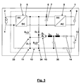
- the switch 15 here consists of two mechanical switches S 3 and S 4 which are printed AC relays and which are used to select between the buck converter 33 and the boost converter 34 for loading the battery 13 or loading the DC voltage link 6 out of the battery 13, respectively.
- the AC relays S 3 and S 4 do not need to cut off a flowing current. This is done by opening the switch S 1 when the AC relay S 4 is closed and by interrupting the pulsed operation of S 2 stopping a current from the battery 13 into the DC voltage link 6 only flowing due to the boosting operation of the boost converter 34 when the AC relay S 3 is closed.
- the controller may also cut off the battery 13 using the switches S 1 to S 4 if commanded by the safety data from the battery monitoring unit. Any fault currents occurring are interrupted by the fuses 14.
Landscapes
- Engineering & Computer Science (AREA)
- Power Engineering (AREA)
- Charge And Discharge Circuits For Batteries Or The Like (AREA)
- Inverter Devices (AREA)
- Supply And Distribution Of Alternating Current (AREA)
- Control Of Electrical Variables (AREA)
Description
- The present invention relates to an inverter apparatus. Especially, the present invention relates to an inverter apparatus for converting electric power from a renewable energy source, whose functionality is enhanced by the potential to store electric energy in a battery. Further, the invention relates to a method of operating such an inverter apparatus.
- The battery may, for example, be used to store electric power from a DC power generator which is at present not needed in a power grid, or to supply electric power needed in the power grid which is at present not available from the DC power generator. Such situations may particularly occur when the power generator is a photovoltaic generator or an electric machine of a wind mill so that the generation of electric power by the power generator is dependent on weather conditions and solar altitude (in case of a photovoltaic generator).
- A battery, however, only has a limited storage capacity. Thus, the state of charge (SOC) of the battery has to be considered in charging and discharging operations. This may be done by monitoring the voltage of the battery. This voltage, however, only represents one of the relevant parameters of the battery. These relevant parameters also include the present temperature of the battery, present maximum or minimum loading or charging currents, present maximum or minimum unloading or discharging currents and the so-called "state of health" (SOH), which is an indicator for the battery long term degradation process.
- John Wynne: "Akkus auf den Zahn gefühlt" (http://www.elektroniknet.de/power/technik-know-how/batterienakkus/article/27123/0/Akkus_auf_den_Zahn_gefuehlt/) discloses a photovoltaic power plant in which a photovoltaic generator is connected to a DC/DC converter. The DC/DC converter is connected to an AC/CD converter feeding AC electric power into a power grid. Battery stacks which buffer the electric energy from the photovoltaic generator are provided between two lines connecting the DC/DC converter to the AC/DC converter. The batteries of the battery stacks are monitored by two independent monitoring systems. A controller controlling both the DC/DC converter and the AC/DC converter receives a battery cell status from the monitoring systems.
-
WO 2009/066880 A2 discloses a high-power, large-capacity battery module including a plurality of battery cells or unit modules connected in series to each other. A battery management system (BMS) is provided for protecting the battery cells from overcharge, overdischarge and overcurrent. The BMS detects and controls the operation of the battery module. When an abnormality of the battery module assembly is detected, the BMS switches a power switch unit to become off such that the charging and discharging operation of the battery module is interrupted. This interruption has a strong impact on any apparatus to which the battery module is connected.
EP 2 346 138 A2US 2012/0249078 A1 discloses a battery system and an energy storage system including a battery module wherein the battery management unit varies a charge limit value for stopping the charging of the at least one battery module.US 2012/223670 A1 discloses a power control device comprising an acquisition unit that acquires voltage information and deterioration information indicating a state of deterioration of a storage battery.US 2008/129249 A1 discloses a battery monitoring unit and sensors that are supplied with a common operating supply voltage, detection values from sensors are sent to a control circuit by the battery monitoring unit.WO 2012/034045 A1 discloses a battery monitoring system including a self-contained measurement device configured to mount to a battery cell.US 2012/089261 A1 discloses a grid connected power storage system wherein an integration controller changes parallel data to be transmitted to a plurality of external devices to serial bit streams and serial bit streams received from the plurality of external devices to parallel data. - There is a strong need for an enhanced integration of a battery in an inverter apparatus.
- The present invention relates to an inverter apparatus comprising a DC voltage link, an input stage connected to the DC voltage link and configured to receive DC electric power from a DC power generator for loading the DC voltage link, a DC/AC converter connected to the DC voltage link and configured to feed AC electric power into a power grid, and a bidirectional connection configured to connect a battery to the DC voltage link, to load the battery out of the DC voltage link and to load the DC voltage link out of the battery. The inverter apparatus further comprises a controller configured to operate the DC/AC converter and the bidirectional connection. The controller is connected to an interface configured to receive present values of relevant parameters of the battery from a battery monitoring unit associated with the battery. The relevant parameters of the battery issued by the battery monitoring unit and received by the interface both include working data related to at least a state of charge of the battery and safety data indicating a safety state of the battery. The controller operates the bidirectional connection dependent on the present values of the relevant parameters of the battery in that it considers the working data in operating the bidirectional connection, and in that it is commanded by the safety data to stop further operation of the bidirectional connection and disconnect the battery by opening suitable switches of the bidirectional connection.
- The interface comprises separate interface units for receiving the working data and the safety data. The controller is configured to receive the safety data as a safety signal only indicating safety of the battery at a signal level within a predetermined safety level range and/or at a signal repetition frequency within a predetermined safety frequency range. As soon as the safety signal is no longer indicating safety of the battery, the operation of the bidirectional connection is interrupted and the battery is disconnected.
- Further, the present invention relates to a method of operating an inverter apparatus which includes a DC voltage link, an input stage connected to the DC voltage link, a DC/AC converter connected to the DC voltage link, and a bidirectional connection connected to the DC voltage link. The method comprises connection a DC power generator to the input stage and loading the DC voltage link with DC electric power received from the DC power generator; operating the DC/AC converter to feed AC electric power into a power grid; connecting a battery to the DC voltage link via the bidirectional connection; and, dependent on present values of relevant parameters of the battery, operating the bidirectional connection to load the battery out of the DC voltage link, or to load the DC voltage link out of the battery. Further, the method comprises receiving the present values of the relevant parameters of the battery from a battery monitoring unit associated with the battery, the relevant parameters of the battery received include working data related to at least a state of charge of the battery and safety data indicating a safety state of the battery; considering the working data in operating the bidirectional connection; and following commands by the safety data to stop further operation of the bidirectional connection and disconnect the battery by opening suitable switches of the bidirectional connection; and receiving the working data and the safety data via separate interface units. Further, the method comprises receiving the safety data as a safety signal only indicating safety of the battery at a signal level within a predetermined safety level range and/or at a signal repetition frequency within a predetermined safety frequency range and as soon as the safety signal is no longer indicating safety of the battery, the operation of the bidirectional connection is interrupted and the battery is disconnected.
- Other features and advantages of the present invention will become apparent to one with skill in the art upon examination of the following drawings and the detailed description. It is intended that all such additional features and advantages be included herein within the scope of the present invention, as defined by the claims.
- The invention will be described and explained with reference to the accompanying drawings. The components in the drawings are not necessarily to scale, emphasis instead being placed upon clearly illustrating the principles of the present invention. In the drawings, like reference numerals designate corresponding parts throughout the several views.
-
Fig. 1 is a schematic circuit diagram of an inverter apparatus according to a first embodiment. -
Fig. 2 shows details of a communication between a controller of the inverter apparatus according toFig. 1 and a battery management unit of a battery connected to this inverter apparatus, and. -
Fig. 3 is a schematic circuit diagram of an inverter apparatus according to another embodiment. - The inverter apparatus of the present invention is configured to integrate all functions needed to safely operate a battery connected to the inverter apparatus. Thus, a battery module comprising the battery may be kept simple. Particularly, neither electrical nor mechanical switches are needed in the battery module.
- According to the present invention, the inverter apparatus is enabled to this integration by cooperating with a battery monitoring unit associated with the battery in the battery module. The battery monitoring unit provides present values of all relevant parameters of the battery to the controller of the inverter apparatus. The battery monitoring unit for example measures the temperature of the battery and any other relevant parameters, like for example individual battery cell voltages. It may also derive maximum or minimum loading or unloading currents allowed in the present state of the battery. Further, the SOC and SOH of the battery may be calculated. However, the battery monitoring unit does not need to care by its own for keeping the present values of the relevant parameters of the battery within the allowed range. This is done by the controller of the inverter dependent on the relevant parameters of the battery.
- According to the present invention the controller of the inverter apparatus considers working data related to at least a state of charge of the battery and operates the bidirectional connection accordingly. These working data are considered by the controller in addition to other data like, for example, the electric power presently provided by a DC power generator or electric power demanded by a power grid connected to the inverter apparatus. As a security measure, however, the relevant parameters of the battery which the controller receives from the battery monitoring unit also include safety data indicating a safety state of the battery. These safety data are not just considered by the controller. Instead, the controller is commanded by the safety data in operating the bidirectional connection. This particularly means that the controller is commanded to stop further operation of the bidirectional connection and disconnect the battery by opening suitable switches of the bidirectional connection. These actions will be executed by the controller which is commanded by the safety data independently of any data from other sources. Due to the direct effect the safety data have on the operation of the bidirectional connection, the battery module may in fact be kept simple and have no own switches for a safety cut-off, for example.
- The different kinds of data received by the controller of the inverter apparatus according to the present invention and their different degree of relevance may be reflected by separate interface units for receiving the working data and the safety data. Further, these interface units may be different. In one embodiment, the interface unit for the working data includes a CAN-bus interface unit. In the same or another embodiment of the inverter apparatus according to the present invention, the interface unit for the safety data is configured to receive a hardware signal. The term "hardware signal" here refers to a signal comprising only two different states which can be processed at a hardware level without any software interpretation needed. For example these two states are two different voltage levels, or in case of a toggled hardware signal these two states may be presence versus absence of that signal.
- In the inverter apparatus according to the present invention, the controller is configured to receive the safety data as a safety signal only indicating safety of the battery at a signal level within a predetermined safety level range and/or at a signal repetition frequency within a predetermined safety frequency range. Thus, for example, the safety signal may indicate no safety at a signal level below a safety threshold level value and/or a signal repetition frequency below a safety threshold frequency value. Only as long as the safety signal is in the safety range(s), the controller regularly operates the bidirectional connection. As soon as the safety signal is no longer indicating safety of the battery, the operation of the bidirectional connection is interrupted and the battery is disconnected.
- The safety signal may be provided by the controller and transmitted to the battery monitoring unit via the interface, and the interface may be configured to only return the safety signal at its original signal level and/or at its original signal repetition frequency to the controller, if the battery is safe. In this embodiment, the safety signal as provided by the controller already qualifies as a "battery safe signal". In a preferred embodiment, however, the safety signal as provided by the controller is not yet indicating a safe battery. In this embodiment, the safety signal will only be converted by the monitoring unit into a "battery safe signal" before it is returned to the controller, if the whole battery module functions properly. Such a conversion of the safety signal requires an action by the properly functioning monitoring unit and may, thus, not be provided by a short circuit. The conversion of the safety signal may, for example, consist of a shift of the signal level or of doubling the signal repetition frequency to get it into the safety level range and/or the safety frequency range, respectively.
- In addition to different interface units for receiving the working data and the safety data, the inverter apparatus may comprise different controller units for processing the working data and the safety data. In one embodiment, the controller unit for the working data may be a freely programmable controller unit, whereas the controller unit for the safety data may be a fixedly programmed controller unit. The programming of the freely programmable controller unit may be altered to adapt the controller to fulfil varying purposes in operating the bidirectional connection. Such purposes may be an optimization of the local consumption of the power produced, e.g. by a PV-generator or feeding the energy in a public grid at times when the feed-in fee is highest or supporting grid stability of the connected public grid.
- In contrast to the freely programmed controller unit the fixed programmed controller unit for the safety data can not be manipulated, and thus no safety function can be deactivated erroneously.
- In a more detailed embodiment, the controller unit for the working data includes a digital signal processor (DSP), and the controller unit for the safety data includes a field programmable gate array (FPGA).
- The working data provided by the battery monitoring unit may also include battery and battery monitoring unit identification data. These data may be issued by the battery monitoring unit at least during start-up of the battery monitoring unit and/or when requested by the controller of the inverter apparatus according to the present invention. Particularly, the battery and battery monitoring unit identification data may include battery monitoring unit software version information. This identification data may be processed by a predefined procedure so that the identification data is verified. In General, the battery and battery monitoring unit identification data indicate whether the controller is able to suitably operate the bidirectional connection considering the working data. Thus, the controller may only operate the bidirectional connection for loading the battery out of the DC voltage link or for loading the DC voltage link out of the battery, if the battery and battery monitoring unit identification data indicate compatibility of the battery and the battery monitoring unit with the inverter apparatus.
- The safety data, however, are not dependent on the particular battery or battery monitoring unit or software version of the battery monitoring unit. The controller of the inverter apparatus according to the present invention will only operate the bidirectional connection, if the safety signal transmitted to the battery monitoring unit is returned and the returned safety signal indicates safety of the battery.
- In one embodiment, the bidirectional connection comprises a bidirectional DC/DC converter operated by the controller. In the same or another embodiment, the bidirectional connection comprises an electrical cut-off switch and a mechanical cut-off switch operated by the controller. The mechanical cut-off switch operated by the controller may comprise an AC print relay. In combination with the electrical cut-off switch, the simple and cost-effective AC print relay is sufficient for permanently cutting off the battery if no safety of the battery is given. If a fault current occurs, the fault current is securely interrupted by cut-off fuses which may be comprised in the controller or the battery module.
- The interface unit for receiving the working data from the battery monitoring unit may be configured to allow for bidirectional communication between the controller of the inverter apparatus and the battery monitoring unit. This bidirectional communication may not only be helpful for sending requests for particular working data from the controller to the battery monitoring unit. The bidirectional interface unit may also be used for programming the battery monitoring unit or for updating software in the battery monitoring unit. This means that the entire external communication of the battery monitoring unit may take place via the bidirectional interface unit, i.e. with the controller of the inverter apparatus. This is a further aspect allowing to keep the battery monitoring unit and the battery very simple.
- The battery module comprising the battery and the battery monitoring unit may be arranged inside or outside a housing of the inverter apparatus of the present invention. This may depend on the size of the battery, for example.
- The battery may comprise a plurality of battery cells, and the inverter apparatus may have more than one bidirectional connection each configured to connect one battery to the same DC voltage link or to separate DC voltage links.
- Taking the inverter apparatus of the present invention and the battery module together, there is a reduction in the number of components due to multiple use of security elements in the inverter apparatus. Further benefits are a higher packaging density which results in a compact housing design and simplifies mounting of the combined installation. Thus, the inverter apparatus of the present invention provides an inverter with battery in a compact and cost-saving design.
- Referring now in greater detail to the drawings,
Fig. 1 schematically depicts aninverter apparatus 1. ADC power generator 2 is connected to aninput stage 3 of theinverter apparatus 1. TheDC power generator 2 is aphotovoltaic generator 4 here. Theinput stage 3 includes a DC/DC converter 5 loading a DC voltage link 6 comprising at least onecapacitor 7 with DC electric power from theDC power generator 2. A DC/AC converter 8 of theinverter apparatus 1 converts the DC electric power from the DC voltage link 6 into AC electric power and feeds this AC electric power into anexternal power grid 9. Further, abattery module 10 is connected to the DC voltage link 6 via abidirectional connection 11 of theinverter apparatus 1. Thebidirectional connection 11 includes a bidirectional DC/DC converter 12 and serves for either loading abattery 13 of thebattery module 10 with DC electric power out of the DC voltage link 6 or for loading the DC voltage link 6 with DC electric power from thebattery 13, as needed. Thebidirectional connection 11 further comprises cut-off fuses 14, a mechanical cut-off switch 15 and a voltmeter measuring the voltage of thebattery 13. The voltage measured by thevoltmeter 16 is considered by acontroller 17 of theinverter apparatus 1, i.e. thecontroller 17 operates the DC/DC converter 12 inter alia depending on the voltage measured by thevoltmeter 16. Thecontroller 17 also operates the DC/AC converter 8 and the DC/DC converter 5. This particularly means that thecontroller 17 provides control signals to all switches in theconverters controller 14 also operates the cut-off switch 15 to cut off thebattery 13 from thebidirectional connection 11 and thus from theinverter apparatus 1. There are further relevant parameters besides the voltage provided by thebattery 13 which should be considered by thecontroller 17 in operating thebidirectional connection 11 as this operation results in currents flowing to thebattery 13 for loading the battery or from thebattery 13 for loading theDC voltage link 6. These parameters for example include the temperature of thebattery 13 or the present minimum or maximum currents from or to thebattery 13 or the presently maximum or minimum allowable voltage across thebattery 13. The present values of these parameters are provided by abattery monitoring unit 18 of thebattery module 10. Thebattery monitoring unit 18 provides these present values as workingdata 19, on the one hand, and assafety data 20, on the other hand. The workingdata 19 are related to at least a state of charge of thebattery 13, and they are considered by thecontroller 17 of theinverter apparatus 1 together with other data depending on a control program running in thecontroller 17. Thesafety data 20 indicate a safety state of thebattery 13 to thecontroller 17. To be absolutely sure that any unsafe condition of thebattery 13 results in a cut-off of thebattery 13 from theinverter 1, thesafety data 20 command thecontroller 17 to directly undertake the necessary steps for this cut-off without any freedom to thecontroller 17. Aninterface 21 via which thecontroller 17 communicates with thebattery monitoring unit 18 comprises dedicatedinterface units data 19 and thesafety data 20 separately transmitted by thebattery monitoring unit 18. Further, thesafety data 20 are based on asafety signal 24 forwarded from thecontroller 17 via theinterface unit 23 to thebattery monitoring unit 18. Thebattery monitoring unit 18 is only able to convert the safety signal, i. e. to alter it with regard to its level and/or frequency, for example, and to return the converted safety signal as thesafety data 19, if thebattery monitoring unit 18 operates properly, and if thebattery 13 monitored by thebattery monitoring unit 18 is safe. Otherwise, thebattery monitoring unit 18, if it returns thesafety signal 24 at all, returns it at its original level and frequency which indicates to thecontroller 17 that something is wrong and that thebattery 13 should be disconnected from theinverter apparatus 1, if it is already connected to it at all. At least, thebidirectional connection 11 should not be further operated regularly. However, it may be operated for securely discharging thebattery 13, if a too high battery voltage indicates an unsafe over-charged state of the battery, or for securely loading thebattery 13, if a too low battery voltage indicates an unsafe over-discharged state of the battery, for example. In these ways a de-escalation of the unsafe states is provided returning the battery into a safe state and avoiding a failure requiring external service of the inverter apparatus or the battery module. - The
interface unit 22 also allows for bidirectional communication between thecontroller 17 and thebattery monitoring unit 18. Thus, thecontroller 17 may sendrequests 25 for the present values of certain parameters to thebattery monitoring unit 18 or even forward software to thebattery monitoring unit 18 for programming it. Thus, thebattery monitoring unit 18 and theentire battery module 10 may only be connected to theinverter apparatus 1 and only communicate with theinverter apparatus 1, whereas thecontroller 17 of theinverter apparatus 1 may also be able to communicate to the outside via afurther interface 26 connecting it to the internet, for example. -
Fig. 2 illustrates that thesafety data 20 and the workingdata 19 are not only forwarded viadifferent interface units interface 21 which may be a CAN-bus interface unit for handling therequests 25 and the workingdata 19 and aninterface unit 23 forwarding thesafety signal 24 to thebattery monitoring unit 18 and returning thesafety data 20 to thecontroller 17, but that these data are also handled by separate components of thebattery monitoring unit 18 and thecontroller 17. Thebattery monitoring unit 18 may comprise twoseparate chips safety data 20 only indicate safety of the battery module if everything is working properly. Thesafety data 20 are processed by a fixed programmedcontroller unit 29 of thecontroller 17 which may also forward thesafety signal 24. Therequests 25 are sent and the workingdata 19 are received by a freelyprogrammable controller unit 30 of thecontroller 17 which, based on these and other data, provides driver signals 31 to adriver 32 for the various switches of theconverters mechanical switch 15 according toFig. 1 . However, the driver signals 31 are selectively forwarded by thecontroller unit 29 depending on the safety state of the battery. If no safety is given, at least the operation of the DC/DC converter 12 according toFig. 1 is stopped and theswitch 15 according toFig. 1 is no longer closed but opened. -
Fig. 3 shows another embodiment of theinverter apparatus 1 and provides more details with regard to the bidirectional DC/DC converter 12. Thevoltmeter 16, thecontroller 17, thebattery monitoring unit 18 and theinterfaces DC converter 12 comprises abuck converter 33 including a switch S1 and a diode D1 for loading thebattery 13, and aboost converter 34 including a diode D2 and a switch S2 for loading the DC voltage link 6 out of thebattery 13. The twoconverters capacitor 7 of theDC voltage link 6 and of afurther capacitor 35. Thecapacitor 35, together with a second inductor L2, also serves as a filter between theconverters battery 13. Theswitch 15 here consists of two mechanical switches S3 and S4 which are printed AC relays and which are used to select between thebuck converter 33 and theboost converter 34 for loading thebattery 13 or loading the DC voltage link 6 out of thebattery 13, respectively. The AC relays S3 and S4, however, do not need to cut off a flowing current. This is done by opening the switch S1 when the AC relay S4 is closed and by interrupting the pulsed operation of S2 stopping a current from thebattery 13 into the DC voltage link 6 only flowing due to the boosting operation of theboost converter 34 when the AC relay S3 is closed. In this way, the controller (not depicted inFig. 3 ) may also cut off thebattery 13 using the switches S1 to S4 if commanded by the safety data from the battery monitoring unit. Any fault currents occurring are interrupted by thefuses 14. -
- 1
- inverter apparatus
- 2
- DC power generator
- 3
- input stage
- 4
- photovoltaic generator
- 5
- DC/DC converter
- 6
- DC voltage link
- 7
- capacitor
- 8
- DC/AC converter
- 9
- power grid
- 10
- battery module
- 11
- bidirectional connection
- 12
- bidirectional DC/DC converter
- 13
- battery
- 14
- fuse
- 15
- switch
- 16
- voltmeter
- 17
- controller
- 18
- battery monitoring unit
- 19
- working data
- 20
- safety data
- 21
- interface
- 22
- interface unit
- 23
- interface unit
- 24
- safety signal
- 25
- requests
- 26
- interface
- 27
- chip
- 28
- chip
- 29
- controller unit
- 30
- controller unit
- 31
- driver signals
- 32
- driver
- 33
- buck converter
- 34
- boost converter
- 35
- capacitor
- L1
- inductor
- L2
- inductor
- S1
- switch
- S2
- switch
- S3
- switch
- S4
- switch
Claims (15)
- An inverter apparatus (1) comprising:- a DC voltage link (6),- an input stage (3) connected to the DC voltage (6) link and configured to receive DC electric power from a DC power generator (2) for loading the DC voltage link (6),- a DC/AC converter (8) connected to the DC voltage link (6) and configured to feed AC electric power into a power grid (9),- a bidirectional connection (11) configured to connect a battery (13) to the DC voltage link (6), to load the battery (13) out of the DC voltage link (6), and to load the DC voltage link (6) out of the battery (13), and- a controller (17) configured to operate the DC/AC converter (8) and, dependent on present values of relevant parameters of the battery (13), to operate the bidirectional connection (11),wherein- the controller (17) is connected to an interface (21) configured to receive the present values of the relevant parameters of the battery (13) from a battery monitoring unit (18) associated with the battery (13),- the relevant parameters of the battery (13) issued by the battery monitoring unit (18) and received by the interface (21) include working data (19) related to at least a state of charge of the battery (13) and safety data (20) indicating a safety state of the battery (13),- the controller (17) is configured to consider the working data in operating the bidirectional connection (11),- the controller (17) is configured to be commanded by the safety data (20) to stop further operation of the bidirectional connection and disconnect the battery by opening suitable switches of the bidirectional connection, and- the interface (21) comprises separate interface units (22, 23) for receiving the working data (19) and the safety data (20),characterized in that the controller (17) is configured to receive the safety data (20) as a safety signal (24) only indicating safety of the battery (13) at a signal level within a predetermined safety level range and/or at a signal repetition frequency within a predetermined safety frequency range and as soon as the safety signal (24) is no longer indicating safety of the battery, the operation of the bidirectional connection is interrupted and the battery is disconnected.
- The inverter apparatus (1) of claim 1, characterized in that the interface unit (22) for the working data (19) includes a CAN-bus interface unit and/or that the interface unit (23) for the safety data (20) is configured to receive a hardware signal.
- The inverter apparatus (1) of claim 1, characterized in that the controller (17) is configured to transmit, via the interface (21), the safety signal (24) to the battery monitoring unit (18).
- The inverter apparatus (1) of any of the claims 1 to 3, characterized in that the controller (17) comprises different controller units (30 and 29) for processing the working data (19) and the safety data (20).
- The inverter apparatus (1) of claim 4, characterized in that the controller unit (30) for the working data (19) is a freely programmable controller unit and that the controller unit (29) for the safety data (20) is a fixedly programmed controller unit.
- The inverter apparatus (1) of any of the claims 1 to 5, characterized in that the working data (19) include battery and battery monitoring unit identification data at least during start-up of the battery monitoring unit (18) or when requested by the controller (17).
- The inverter apparatus (1) of claim 6, characterized in that the battery and battery monitoring unit identification data include battery monitoring unit software version information and that the controller (17) only operates the bidirectional connection (11) for loading the battery (13) out of the DC voltage link (6) or for loading the DC voltage link (6) out of the battery (13), if the battery and battery monitoring unit identification data indicate compatibility of the battery (13) and the battery monitoring unit (18) with the inverter apparatus (1).
- The inverter apparatus (1) of any of the claims 1 to 7, characterized in that the bidirectional connection (11) comprises at least one electrical cut-off switch (S1, S2) and at least one mechanical cut-off switch (15, S3, S4) operated by the controller (17).
- The inverter apparatus (1) of claim 8, characterized in that the at least one mechanical cut-off switch (S3, S4) operated by the controller (17) comprises an AC print relay.
- The inverter apparatus (1) of any of the claims 1 to claim 9, characterized in that the battery (13) is arranged within a housing enclosing the inverter apparatus and the battery is part of an interchangeable battery module including the battery monitoring unit (18).
- A method of operating an inverter apparatus (1) including:- a DC voltage link (6),- an input stage (3) connected to the DC voltage (6) link,- a DC/AC converter (8) connected to the DC voltage link (6), and- a bidirectional connection (11) connected to the DC voltage link (6),the method comprising:- connecting a DC power generator (2) to the input stage (3) and loading the DC voltage link (6) with DC electric power received from the DC power generator (2);- operating the DC/AC converter (8) to feed AC electric power into a power grid (9);- connecting a battery (13) to the DC voltage link (6) via the bidirectional connection (11); and- dependent on present values of relevant parameters of the battery (13), operating the bidirectional connection (11) to load the battery (13) out of the DC voltage link (6), or to load the DC voltage link (6) out of the battery (13);- receiving the present values of the relevant parameters of the battery (13) from a battery monitoring unit (18) associated with the battery (13), the received relevant parameters of the battery (13) include working data (19) related to at least a state of charge of the battery (13) and safety data (20) indicating a safety state of the battery (13);- considering the working data in operating the bidirectional connection (11);- following commands by the safety data (20) to stop further operation of the bidirectional connection and disconnect the battery by opening suitable switches of the bidirectional connection and- receiving the working data (19) and the safety data (20) via separate interface units (22, 23);characterized by- receiving the safety data (19) as a safety signal (24) only indicating safety of the battery (13) at a signal level within a predetermined safety level range and/or at a signal repetition frequency within a predetermined safety frequency range and as soon as the safety signal (24) is no longer indicating safety of the battery, the operation of the bidirectional connection is interrupted and the battery is disconnected.
- The method of claim 11, characterized by transmitting the safety signal (24) to the battery monitoring unit (18).
- The method of claim 12, characterized by transmitting the safety signal (24) at a signal level outside the predetermined safety level range and/or at a signal repetition frequency outside the predetermined safety frequency range.
- The method of any of the claims 11 to 12, characterized by processing the working data (19) and the safety data (20) in different controller units (30 and 29).
- The method of any of the claims 11 to 14, characterized by only operating the bidirectional connection (11) for loading the battery (13) out of the DC voltage link (6) or for loading the DC voltage link (6) out of the battery (13), if battery and battery monitoring unit identification data included in that the working data (19) indicate compatibility of the battery (13) and the battery monitoring unit (18) with the inverter apparatus (1).
Applications Claiming Priority (1)
| Application Number | Priority Date | Filing Date | Title |
|---|---|---|---|
| PCT/EP2012/074929 WO2014090273A1 (en) | 2012-12-10 | 2012-12-10 | Security concept for integrating a battery into an inverter |
Publications (2)
| Publication Number | Publication Date |
|---|---|
| EP2926431A1 EP2926431A1 (en) | 2015-10-07 |
| EP2926431B1 true EP2926431B1 (en) | 2016-08-10 |
Family
ID=47351655
Family Applications (1)
| Application Number | Title | Priority Date | Filing Date |
|---|---|---|---|
| EP12799175.0A Active EP2926431B1 (en) | 2012-12-10 | 2012-12-10 | Security concept for integrating a battery into an inverter |
Country Status (5)
| Country | Link |
|---|---|
| US (1) | US9866023B2 (en) |
| EP (1) | EP2926431B1 (en) |
| JP (1) | JP6141442B2 (en) |
| CN (1) | CN104871387B (en) |
| WO (1) | WO2014090273A1 (en) |
Families Citing this family (9)
| Publication number | Priority date | Publication date | Assignee | Title |
|---|---|---|---|---|
| EP3159998A1 (en) * | 2015-10-20 | 2017-04-26 | AmbiBox GmbH | Actuator, system with actuator, energy supply unit for a vehicle on-board network, air conditioning device, power supply for electronic circuits, system for supplying energy to computing centre units, dc charger for electric vehicles |
| CN105870998B (en) * | 2016-04-06 | 2018-07-24 | 国家电网公司 | A kind of rectification module dormancy control method of transformer station direct current system |
| US11309714B2 (en) * | 2016-11-02 | 2022-04-19 | Tesla, Inc. | Micro-batteries for energy generation systems |
| DE102017004171A1 (en) * | 2017-04-27 | 2018-10-31 | Kostal Industrie Elektrik Gmbh | Inverter assembly |
| IT201700060644A1 (en) * | 2017-06-01 | 2018-12-01 | Convert Tech S R L | System to energize alternating current electrical loads in a photovoltaic system |
| ES2978213T3 (en) | 2017-05-12 | 2024-09-09 | Convert Tech S R L | System for energizing electrical loads with alternating current in a photovoltaic plant |
| EP3562019B1 (en) * | 2018-04-26 | 2021-03-03 | ams AG | Inverter circuit arrangement |
| KR102371197B1 (en) * | 2020-02-10 | 2022-03-07 | 삼성에스디아이 주식회사 | Protection system of energy storage system |
| KR102614863B1 (en) * | 2021-08-04 | 2023-12-19 | 서울대학교산학협력단 | Bi-directional dc/ac power conversion system having dc multiple dc links |
Citations (6)
| Publication number | Priority date | Publication date | Assignee | Title |
|---|---|---|---|---|
| US20080129249A1 (en) | 2005-03-17 | 2008-06-05 | Toyota Jidosha Kabushiki Kaisha | Monitoring Device for Power Supply System |
| EP2346138A2 (en) | 2010-01-18 | 2011-07-20 | Samsung SDI Co., Ltd. | Power storage apparatus |
| WO2012034045A1 (en) | 2010-09-10 | 2012-03-15 | Johnson Controls Technology Company | Vehicle battery monitoring system |
| US20120089261A1 (en) | 2010-10-06 | 2012-04-12 | Samsung Sdi Co., Ltd. | Grid connected power storage system and integration controller thereof |
| US20120223670A1 (en) | 2010-09-10 | 2012-09-06 | Tatsuto Kinjo | Power control device, power control method, and power supply system |
| US20120249078A1 (en) | 2011-03-31 | 2012-10-04 | Samsung Sdi Co., Ltd. | Battery system and energy storage system including the same |
Family Cites Families (13)
| Publication number | Priority date | Publication date | Assignee | Title |
|---|---|---|---|---|
| US5850351A (en) * | 1996-04-25 | 1998-12-15 | General Motors Corporation | Distributed management apparatus for battery pack |
| EP0954001A1 (en) * | 1998-04-30 | 1999-11-03 | ELESTA relays GmbH | Relay with guided contacts |
| EP2270526A1 (en) * | 2003-07-09 | 2011-01-05 | Premium Power Corporation | Device for monitoring and charging of a selected group of battery cells |
| WO2006044693A2 (en) | 2004-10-18 | 2006-04-27 | Black & Decker Inc. | Cordless power system |
| CN101861666B (en) | 2007-11-21 | 2014-08-13 | 株式会社Lg化学 | Battery module with improved safety and medium or large battery pack containing same |
| JP4770918B2 (en) * | 2008-11-18 | 2011-09-14 | ソニー株式会社 | Battery pack and control method |
| JP2010178495A (en) * | 2009-01-29 | 2010-08-12 | Panasonic Corp | Power conversion apparatus and power conversion system |
| US9762069B2 (en) | 2009-05-19 | 2017-09-12 | Duracell U.S. Operations, Inc. | Multi-use fast rate charging stand |
| KR101084214B1 (en) * | 2009-12-03 | 2011-11-18 | 삼성에스디아이 주식회사 | Grid-connected power storage system and control method of power storage system |
| KR101146670B1 (en) * | 2009-12-16 | 2012-05-23 | 삼성에스디아이 주식회사 | Energy management system and method for controlling thereof |
| WO2011128962A1 (en) * | 2010-04-12 | 2011-10-20 | 東芝三菱電機産業システム株式会社 | Power conversion device |
| EP2458704A1 (en) * | 2010-11-30 | 2012-05-30 | Restore N.V. | Method and system for charging a fleet of batteries |
| KR20130104771A (en) * | 2012-03-15 | 2013-09-25 | 삼성에스디아이 주식회사 | Energy storage system and control method thereof |
-
2012
- 2012-12-10 EP EP12799175.0A patent/EP2926431B1/en active Active
- 2012-12-10 CN CN201280077390.1A patent/CN104871387B/en active Active
- 2012-12-10 WO PCT/EP2012/074929 patent/WO2014090273A1/en not_active Ceased
- 2012-12-10 JP JP2015545679A patent/JP6141442B2/en active Active
-
2015
- 2015-06-09 US US14/734,354 patent/US9866023B2/en active Active
Patent Citations (6)
| Publication number | Priority date | Publication date | Assignee | Title |
|---|---|---|---|---|
| US20080129249A1 (en) | 2005-03-17 | 2008-06-05 | Toyota Jidosha Kabushiki Kaisha | Monitoring Device for Power Supply System |
| EP2346138A2 (en) | 2010-01-18 | 2011-07-20 | Samsung SDI Co., Ltd. | Power storage apparatus |
| WO2012034045A1 (en) | 2010-09-10 | 2012-03-15 | Johnson Controls Technology Company | Vehicle battery monitoring system |
| US20120223670A1 (en) | 2010-09-10 | 2012-09-06 | Tatsuto Kinjo | Power control device, power control method, and power supply system |
| US20120089261A1 (en) | 2010-10-06 | 2012-04-12 | Samsung Sdi Co., Ltd. | Grid connected power storage system and integration controller thereof |
| US20120249078A1 (en) | 2011-03-31 | 2012-10-04 | Samsung Sdi Co., Ltd. | Battery system and energy storage system including the same |
Non-Patent Citations (2)
| Title |
|---|
| "ATMEL Li-Ion Battery Management Monitoring Emergency and Backup Circuit ATA6871", ATMEL, July 2009 (2009-07-01), XP002717254 |
| "Atmel Li-Ion Battery Management Solution doc9019", ATMEL, 2011, pages 1 - 7, XP055379755 |
Also Published As
| Publication number | Publication date |
|---|---|
| US20150288185A1 (en) | 2015-10-08 |
| WO2014090273A1 (en) | 2014-06-19 |
| CN104871387B (en) | 2017-09-22 |
| US9866023B2 (en) | 2018-01-09 |
| CN104871387A (en) | 2015-08-26 |
| JP2016506710A (en) | 2016-03-03 |
| EP2926431A1 (en) | 2015-10-07 |
| JP6141442B2 (en) | 2017-06-07 |
Similar Documents
| Publication | Publication Date | Title |
|---|---|---|
| US9866023B2 (en) | Security concept for integrating a battery into an inverter | |
| EP2610993A1 (en) | Power supply device | |
| JP6245735B2 (en) | Battery system and energy storage system | |
| JP6228666B2 (en) | Battery system | |
| KR102479719B1 (en) | System and Method for Controlling Battery | |
| EP1706937B1 (en) | Dc/dc converter and decentralized power generation system comprising a dc/dc converter | |
| EP3490096B1 (en) | Battery system | |
| US7566981B2 (en) | Actuating drive and emergency energy supply device | |
| CA3147556A1 (en) | Systems and methods for fail-safe battery protection independent from battery management system | |
| KR20120082876A (en) | Electricity storage system and control device | |
| EP2808687A1 (en) | Battery system, and ground-fault detection device | |
| EP2658027A1 (en) | Power supply system | |
| JP5497421B2 (en) | Multi-series lithium ion secondary battery information transmission system | |
| JP2013206643A (en) | Relay fusion detector of battery system, and battery system using the same | |
| EP2645734B1 (en) | Battery system | |
| KR20150085383A (en) | Battery system, energy storage system including the battery system | |
| CN104937808B (en) | Controlling equipment for electric flux storage system | |
| US20140354236A1 (en) | Battery management system and driving method thereof | |
| GB2545698A (en) | Multi-module battery control | |
| JP5361594B2 (en) | Lithium ion secondary battery system and power supply method to management device | |
| CN111095719B (en) | battery device | |
| WO2015040655A1 (en) | Switching device and storage battery system | |
| CN112531853B (en) | Main battery system management unit and protection method of battery single cabinet group parallel charging and discharging system | |
| JP7109294B2 (en) | Power supply system and power grid connection system | |
| CN119109204A (en) | An intelligent distributed power supply and distribution system for aircraft |
Legal Events
| Date | Code | Title | Description |
|---|---|---|---|
| PUAI | Public reference made under article 153(3) epc to a published international application that has entered the european phase |
Free format text: ORIGINAL CODE: 0009012 |
|
| 17P | Request for examination filed |
Effective date: 20150629 |
|
| AK | Designated contracting states |
Kind code of ref document: A1 Designated state(s): AL AT BE BG CH CY CZ DE DK EE ES FI FR GB GR HR HU IE IS IT LI LT LU LV MC MK MT NL NO PL PT RO RS SE SI SK SM TR |
|
| AX | Request for extension of the european patent |
Extension state: BA ME |
|
| 17Q | First examination report despatched |
Effective date: 20151204 |
|
| DAX | Request for extension of the european patent (deleted) | ||
| GRAP | Despatch of communication of intention to grant a patent |
Free format text: ORIGINAL CODE: EPIDOSNIGR1 |
|
| INTG | Intention to grant announced |
Effective date: 20160426 |
|
| GRAS | Grant fee paid |
Free format text: ORIGINAL CODE: EPIDOSNIGR3 |
|
| GRAA | (expected) grant |
Free format text: ORIGINAL CODE: 0009210 |
|
| AK | Designated contracting states |
Kind code of ref document: B1 Designated state(s): AL AT BE BG CH CY CZ DE DK EE ES FI FR GB GR HR HU IE IS IT LI LT LU LV MC MK MT NL NO PL PT RO RS SE SI SK SM TR |
|
| REG | Reference to a national code |
Ref country code: GB Ref legal event code: FG4D |
|
| REG | Reference to a national code |
Ref country code: CH Ref legal event code: EP Ref country code: AT Ref legal event code: REF Ref document number: 819808 Country of ref document: AT Kind code of ref document: T Effective date: 20160815 |
|
| REG | Reference to a national code |
Ref country code: IE Ref legal event code: FG4D |
|
| REG | Reference to a national code |
Ref country code: DE Ref legal event code: R096 Ref document number: 602012021597 Country of ref document: DE |
|
| REG | Reference to a national code |
Ref country code: NL Ref legal event code: FP |
|
| REG | Reference to a national code |
Ref country code: LT Ref legal event code: MG4D |
|
| REG | Reference to a national code |
Ref country code: FR Ref legal event code: PLFP Year of fee payment: 5 |
|
| REG | Reference to a national code |
Ref country code: AT Ref legal event code: MK05 Ref document number: 819808 Country of ref document: AT Kind code of ref document: T Effective date: 20160810 |
|
| PG25 | Lapsed in a contracting state [announced via postgrant information from national office to epo] |
Ref country code: RS Free format text: LAPSE BECAUSE OF FAILURE TO SUBMIT A TRANSLATION OF THE DESCRIPTION OR TO PAY THE FEE WITHIN THE PRESCRIBED TIME-LIMIT Effective date: 20160810 Ref country code: FI Free format text: LAPSE BECAUSE OF FAILURE TO SUBMIT A TRANSLATION OF THE DESCRIPTION OR TO PAY THE FEE WITHIN THE PRESCRIBED TIME-LIMIT Effective date: 20160810 Ref country code: HR Free format text: LAPSE BECAUSE OF FAILURE TO SUBMIT A TRANSLATION OF THE DESCRIPTION OR TO PAY THE FEE WITHIN THE PRESCRIBED TIME-LIMIT Effective date: 20160810 Ref country code: IS Free format text: LAPSE BECAUSE OF FAILURE TO SUBMIT A TRANSLATION OF THE DESCRIPTION OR TO PAY THE FEE WITHIN THE PRESCRIBED TIME-LIMIT Effective date: 20161210 Ref country code: NO Free format text: LAPSE BECAUSE OF FAILURE TO SUBMIT A TRANSLATION OF THE DESCRIPTION OR TO PAY THE FEE WITHIN THE PRESCRIBED TIME-LIMIT Effective date: 20161110 Ref country code: LT Free format text: LAPSE BECAUSE OF FAILURE TO SUBMIT A TRANSLATION OF THE DESCRIPTION OR TO PAY THE FEE WITHIN THE PRESCRIBED TIME-LIMIT Effective date: 20160810 |
|
| PG25 | Lapsed in a contracting state [announced via postgrant information from national office to epo] |
Ref country code: PT Free format text: LAPSE BECAUSE OF FAILURE TO SUBMIT A TRANSLATION OF THE DESCRIPTION OR TO PAY THE FEE WITHIN THE PRESCRIBED TIME-LIMIT Effective date: 20161212 Ref country code: GR Free format text: LAPSE BECAUSE OF FAILURE TO SUBMIT A TRANSLATION OF THE DESCRIPTION OR TO PAY THE FEE WITHIN THE PRESCRIBED TIME-LIMIT Effective date: 20161111 Ref country code: SE Free format text: LAPSE BECAUSE OF FAILURE TO SUBMIT A TRANSLATION OF THE DESCRIPTION OR TO PAY THE FEE WITHIN THE PRESCRIBED TIME-LIMIT Effective date: 20160810 Ref country code: LV Free format text: LAPSE BECAUSE OF FAILURE TO SUBMIT A TRANSLATION OF THE DESCRIPTION OR TO PAY THE FEE WITHIN THE PRESCRIBED TIME-LIMIT Effective date: 20160810 Ref country code: AT Free format text: LAPSE BECAUSE OF FAILURE TO SUBMIT A TRANSLATION OF THE DESCRIPTION OR TO PAY THE FEE WITHIN THE PRESCRIBED TIME-LIMIT Effective date: 20160810 Ref country code: ES Free format text: LAPSE BECAUSE OF FAILURE TO SUBMIT A TRANSLATION OF THE DESCRIPTION OR TO PAY THE FEE WITHIN THE PRESCRIBED TIME-LIMIT Effective date: 20160810 Ref country code: PL Free format text: LAPSE BECAUSE OF FAILURE TO SUBMIT A TRANSLATION OF THE DESCRIPTION OR TO PAY THE FEE WITHIN THE PRESCRIBED TIME-LIMIT Effective date: 20160810 |
|
| PG25 | Lapsed in a contracting state [announced via postgrant information from national office to epo] |
Ref country code: RO Free format text: LAPSE BECAUSE OF FAILURE TO SUBMIT A TRANSLATION OF THE DESCRIPTION OR TO PAY THE FEE WITHIN THE PRESCRIBED TIME-LIMIT Effective date: 20160810 Ref country code: EE Free format text: LAPSE BECAUSE OF FAILURE TO SUBMIT A TRANSLATION OF THE DESCRIPTION OR TO PAY THE FEE WITHIN THE PRESCRIBED TIME-LIMIT Effective date: 20160810 |
|
| REG | Reference to a national code |
Ref country code: DE Ref legal event code: R026 Ref document number: 602012021597 Country of ref document: DE |
|
| PLBI | Opposition filed |
Free format text: ORIGINAL CODE: 0009260 |
|
| PG25 | Lapsed in a contracting state [announced via postgrant information from national office to epo] |
Ref country code: BG Free format text: LAPSE BECAUSE OF FAILURE TO SUBMIT A TRANSLATION OF THE DESCRIPTION OR TO PAY THE FEE WITHIN THE PRESCRIBED TIME-LIMIT Effective date: 20161110 Ref country code: SK Free format text: LAPSE BECAUSE OF FAILURE TO SUBMIT A TRANSLATION OF THE DESCRIPTION OR TO PAY THE FEE WITHIN THE PRESCRIBED TIME-LIMIT Effective date: 20160810 Ref country code: CZ Free format text: LAPSE BECAUSE OF FAILURE TO SUBMIT A TRANSLATION OF THE DESCRIPTION OR TO PAY THE FEE WITHIN THE PRESCRIBED TIME-LIMIT Effective date: 20160810 Ref country code: DK Free format text: LAPSE BECAUSE OF FAILURE TO SUBMIT A TRANSLATION OF THE DESCRIPTION OR TO PAY THE FEE WITHIN THE PRESCRIBED TIME-LIMIT Effective date: 20160810 Ref country code: SM Free format text: LAPSE BECAUSE OF FAILURE TO SUBMIT A TRANSLATION OF THE DESCRIPTION OR TO PAY THE FEE WITHIN THE PRESCRIBED TIME-LIMIT Effective date: 20160810 |
|
| 26 | Opposition filed |
Opponent name: LEOPOLD KOSTAL GMBH & CO. KG Effective date: 20170502 |
|
| PLAX | Notice of opposition and request to file observation + time limit sent |
Free format text: ORIGINAL CODE: EPIDOSNOBS2 |
|
| REG | Reference to a national code |
Ref country code: CH Ref legal event code: PL |
|
| PG25 | Lapsed in a contracting state [announced via postgrant information from national office to epo] |
Ref country code: SI Free format text: LAPSE BECAUSE OF FAILURE TO SUBMIT A TRANSLATION OF THE DESCRIPTION OR TO PAY THE FEE WITHIN THE PRESCRIBED TIME-LIMIT Effective date: 20160810 |
|
| PG25 | Lapsed in a contracting state [announced via postgrant information from national office to epo] |
Ref country code: MC Free format text: LAPSE BECAUSE OF FAILURE TO SUBMIT A TRANSLATION OF THE DESCRIPTION OR TO PAY THE FEE WITHIN THE PRESCRIBED TIME-LIMIT Effective date: 20160810 |
|
| REG | Reference to a national code |
Ref country code: IE Ref legal event code: MM4A |
|
| PLBB | Reply of patent proprietor to notice(s) of opposition received |
Free format text: ORIGINAL CODE: EPIDOSNOBS3 |
|
| PG25 | Lapsed in a contracting state [announced via postgrant information from national office to epo] |
Ref country code: CH Free format text: LAPSE BECAUSE OF NON-PAYMENT OF DUE FEES Effective date: 20161231 Ref country code: LU Free format text: LAPSE BECAUSE OF NON-PAYMENT OF DUE FEES Effective date: 20161210 Ref country code: LI Free format text: LAPSE BECAUSE OF NON-PAYMENT OF DUE FEES Effective date: 20161231 |
|
| PG25 | Lapsed in a contracting state [announced via postgrant information from national office to epo] |
Ref country code: IE Free format text: LAPSE BECAUSE OF NON-PAYMENT OF DUE FEES Effective date: 20161210 |
|
| REG | Reference to a national code |
Ref country code: FR Ref legal event code: PLFP Year of fee payment: 6 |
|
| PG25 | Lapsed in a contracting state [announced via postgrant information from national office to epo] |
Ref country code: HU Free format text: LAPSE BECAUSE OF FAILURE TO SUBMIT A TRANSLATION OF THE DESCRIPTION OR TO PAY THE FEE WITHIN THE PRESCRIBED TIME-LIMIT; INVALID AB INITIO Effective date: 20121210 |
|
| PG25 | Lapsed in a contracting state [announced via postgrant information from national office to epo] |
Ref country code: CY Free format text: LAPSE BECAUSE OF FAILURE TO SUBMIT A TRANSLATION OF THE DESCRIPTION OR TO PAY THE FEE WITHIN THE PRESCRIBED TIME-LIMIT Effective date: 20160810 Ref country code: MK Free format text: LAPSE BECAUSE OF FAILURE TO SUBMIT A TRANSLATION OF THE DESCRIPTION OR TO PAY THE FEE WITHIN THE PRESCRIBED TIME-LIMIT Effective date: 20160810 |
|
| PG25 | Lapsed in a contracting state [announced via postgrant information from national office to epo] |
Ref country code: MT Free format text: LAPSE BECAUSE OF NON-PAYMENT OF DUE FEES Effective date: 20161210 |
|
| REG | Reference to a national code |
Ref country code: DE Ref legal event code: R100 Ref document number: 602012021597 Country of ref document: DE |
|
| PG25 | Lapsed in a contracting state [announced via postgrant information from national office to epo] |
Ref country code: TR Free format text: LAPSE BECAUSE OF FAILURE TO SUBMIT A TRANSLATION OF THE DESCRIPTION OR TO PAY THE FEE WITHIN THE PRESCRIBED TIME-LIMIT Effective date: 20160810 Ref country code: AL Free format text: LAPSE BECAUSE OF FAILURE TO SUBMIT A TRANSLATION OF THE DESCRIPTION OR TO PAY THE FEE WITHIN THE PRESCRIBED TIME-LIMIT Effective date: 20160810 |
|
| PLCK | Communication despatched that opposition was rejected |
Free format text: ORIGINAL CODE: EPIDOSNREJ1 |
|
| PLBN | Opposition rejected |
Free format text: ORIGINAL CODE: 0009273 |
|
| STAA | Information on the status of an ep patent application or granted ep patent |
Free format text: STATUS: OPPOSITION REJECTED |
|
| 27O | Opposition rejected |
Effective date: 20181018 |
|
| PGFP | Annual fee paid to national office [announced via postgrant information from national office to epo] |
Ref country code: GB Payment date: 20251218 Year of fee payment: 14 |
|
| PGFP | Annual fee paid to national office [announced via postgrant information from national office to epo] |
Ref country code: FR Payment date: 20251217 Year of fee payment: 14 Ref country code: NL Payment date: 20251217 Year of fee payment: 14 |
|
| PGFP | Annual fee paid to national office [announced via postgrant information from national office to epo] |
Ref country code: BE Payment date: 20251223 Year of fee payment: 14 |
|
| PGFP | Annual fee paid to national office [announced via postgrant information from national office to epo] |
Ref country code: DE Payment date: 20251222 Year of fee payment: 14 |
|
| PGFP | Annual fee paid to national office [announced via postgrant information from national office to epo] |
Ref country code: IT Payment date: 20251231 Year of fee payment: 14 |