EP2926061B1 - Control of solar tracker device - Google Patents
Control of solar tracker device Download PDFInfo
- Publication number
- EP2926061B1 EP2926061B1 EP13792305.8A EP13792305A EP2926061B1 EP 2926061 B1 EP2926061 B1 EP 2926061B1 EP 13792305 A EP13792305 A EP 13792305A EP 2926061 B1 EP2926061 B1 EP 2926061B1
- Authority
- EP
- European Patent Office
- Prior art keywords
- power supply
- tracker device
- tracker
- solar
- support means
- Prior art date
- Legal status (The legal status is an assumption and is not a legal conclusion. Google has not performed a legal analysis and makes no representation as to the accuracy of the status listed.)
- Active
Links
Images


Classifications
-
- F—MECHANICAL ENGINEERING; LIGHTING; HEATING; WEAPONS; BLASTING
- F24—HEATING; RANGES; VENTILATING
- F24S—SOLAR HEAT COLLECTORS; SOLAR HEAT SYSTEMS
- F24S50/00—Arrangements for controlling solar heat collectors
- F24S50/60—Arrangements for controlling solar heat collectors responsive to wind
-
- F—MECHANICAL ENGINEERING; LIGHTING; HEATING; WEAPONS; BLASTING
- F24—HEATING; RANGES; VENTILATING
- F24S—SOLAR HEAT COLLECTORS; SOLAR HEAT SYSTEMS
- F24S40/00—Safety or protection arrangements of solar heat collectors; Preventing malfunction of solar heat collectors
-
- F—MECHANICAL ENGINEERING; LIGHTING; HEATING; WEAPONS; BLASTING
- F24—HEATING; RANGES; VENTILATING
- F24S—SOLAR HEAT COLLECTORS; SOLAR HEAT SYSTEMS
- F24S40/00—Safety or protection arrangements of solar heat collectors; Preventing malfunction of solar heat collectors
- F24S40/80—Accommodating differential expansion of solar collector elements
- F24S40/85—Arrangements for protecting solar collectors against adverse weather conditions
-
- F—MECHANICAL ENGINEERING; LIGHTING; HEATING; WEAPONS; BLASTING
- F24—HEATING; RANGES; VENTILATING
- F24S—SOLAR HEAT COLLECTORS; SOLAR HEAT SYSTEMS
- F24S50/00—Arrangements for controlling solar heat collectors
- F24S50/20—Arrangements for controlling solar heat collectors for tracking
-
- H—ELECTRICITY
- H02—GENERATION; CONVERSION OR DISTRIBUTION OF ELECTRIC POWER
- H02S—GENERATION OF ELECTRIC POWER BY CONVERSION OF INFRARED RADIATION, VISIBLE LIGHT OR ULTRAVIOLET LIGHT, e.g. USING PHOTOVOLTAIC [PV] MODULES
- H02S20/00—Supporting structures for PV modules
- H02S20/30—Supporting structures being movable or adjustable, e.g. for angle adjustment
- H02S20/32—Supporting structures being movable or adjustable, e.g. for angle adjustment specially adapted for solar tracking
-
- Y—GENERAL TAGGING OF NEW TECHNOLOGICAL DEVELOPMENTS; GENERAL TAGGING OF CROSS-SECTIONAL TECHNOLOGIES SPANNING OVER SEVERAL SECTIONS OF THE IPC; TECHNICAL SUBJECTS COVERED BY FORMER USPC CROSS-REFERENCE ART COLLECTIONS [XRACs] AND DIGESTS
- Y02—TECHNOLOGIES OR APPLICATIONS FOR MITIGATION OR ADAPTATION AGAINST CLIMATE CHANGE
- Y02E—REDUCTION OF GREENHOUSE GAS [GHG] EMISSIONS, RELATED TO ENERGY GENERATION, TRANSMISSION OR DISTRIBUTION
- Y02E10/00—Energy generation through renewable energy sources
- Y02E10/40—Solar thermal energy, e.g. solar towers
- Y02E10/47—Mountings or tracking
-
- Y—GENERAL TAGGING OF NEW TECHNOLOGICAL DEVELOPMENTS; GENERAL TAGGING OF CROSS-SECTIONAL TECHNOLOGIES SPANNING OVER SEVERAL SECTIONS OF THE IPC; TECHNICAL SUBJECTS COVERED BY FORMER USPC CROSS-REFERENCE ART COLLECTIONS [XRACs] AND DIGESTS
- Y02—TECHNOLOGIES OR APPLICATIONS FOR MITIGATION OR ADAPTATION AGAINST CLIMATE CHANGE
- Y02E—REDUCTION OF GREENHOUSE GAS [GHG] EMISSIONS, RELATED TO ENERGY GENERATION, TRANSMISSION OR DISTRIBUTION
- Y02E10/00—Energy generation through renewable energy sources
- Y02E10/50—Photovoltaic [PV] energy
Definitions
- the present invention relates to a central safety system for solar tracker devices and their tracker control units in a solar power plant.
- Solar energy systems comprise solar modules including solar cell arrays.
- apparatuses for tracking the modules to the current position of the sun are known in the art.
- the tracker apparatuses are provided for optimizing the electrical output power of the solar modules by following the path of the sun crossing the sky or by employing calculation of ephemerides.
- Two-axes trackers allow for angular motion of the solar modules about the horizontal axis ("tilt") and angular motion about the vertical axis ("rotation").
- Tracker apparatuses are necessary in concentrator photovoltaic (CPV) systems wherein they can guarantee that the solar radiation impinges (almost) vertically on the concentrator optics.
- CPV concentrator photovoltaic
- a typical tracker apparatus comprises a tracker table or frame on which the photovoltaic module is mounted, mechanical actuators (e.g., electrically driven motors) for adjusting the tracker table and a (vertical) column or rod for holding the actuators and the tracker table.
- mechanical actuators e.g., electrically driven motors
- a (vertical) column or rod for holding the actuators and the tracker table.
- the tracker table has to be moved into a "safety position", i.e., basically horizontally, in order to prevent any damage done to the tracker table and the mounted photovoltaic module.
- central communication systems control the tracker apparatus to change the tracker table to a safety position by means of communication lines.
- US 2009/188488 A1 discloses for example a method, for controlling a tracker device of a solar module of a solar power plant with such a system, wherein the solar power plant comprises a central safety system, and wherein the tracker device comprises a control unit, an actuator element and a support means for supporting the solar module.
- the above-mentioned problem is solved by the method for controlling a tracker device of a solar module of a solar power plant, wherein the solar power plant comprises a central safety system and wherein the tracker device comprises a control unit, an actuator element and a support means for supporting the solar module, comprising the steps of
- control unit of the tracker device is also named tracker control unit.
- all tracker devices of the solar power plant can be controlled as described above.
- the solar module comprises an array of solar cells and, in principle, can be any solar module known in the art.
- the solar module may employ some concentrator optics comprising mirrors and/or lenses for focusing solar rays to the solar cells.
- the support means for supporting the solar module can be a tracker table or some frame comprising bars for mounting the solar module.
- the bars can be horizontal and/or vertical bars.
- the particular event can be any event of danger, for example, a predetermined threshold for a wind velocity measured in the vicinity of the solar module or somewhere else being exceeded.
- Other events of danger comprise a power breakdown of the electrical grid, in particular, the electrical grid wherein power gained by the solar power plant is fed or the electrical grid used for operation of the solar power plant, or some failure of a control system controlling crucial parts of the solar power plant.
- the particular position can particularly be a position in that the support means (and thereby the solar module) is oriented substantially horizontally.
- substantially horizontally in particular, a position with an angle of the main plane of the support means (solar module) to a vertical axis that is perpendicular to an essentially horizontally oriented ground plane whereupon the tracker device is installed of between 70° to 110° and more particularly 80° to 100° or 85° to 95° is covered.
- a position essentially parallel (within some ⁇ 20°, in particular, some ⁇ 10°, more particularly, some ⁇ 5°) to the ground whereupon the tracker device is installed is covered.
- the support means can be mounted on a vertical column (which may be rotatable) and in this case “substantially" horizontally covers a position wherein the support means is inclined to the vertical column within a range of angles of 70° to 110° and more particularly 80° to 100° or 85° to 95°.
- the particular position can particularly be oriented substantially vertically in order to avoid and reduce the impact on solar modules.
- the predetermined time period of interruption of electrical power supplied to the tracker device can arbitrarily be chosen and can be in the range of some seconds or minutes (depending on the used control unit of the tracker device), in particular, of about 1 to 5 seconds.
- the interruption and resumption of the electrical power supply causes the tracker device to move the support means (and, thus, the solar module mounted thereon) into the particular position, in particular, the safety position in order to prevent damage of the solar module or avoid unnecessary operation of the same (for example, in the case of a power breakdown of the electrical grid wherein electric energy generated by the solar plant shall be fed).
- indispensable power lines can be used for communicating the emergency signal to the control unit of the tracker device that has to move the support means into the particular position. Operation of the solar tracker devices does thus not depend on a communication via a communication line between a central communication system and the tracker control unit.
- the step of detecting the particular event can be performed by means of a plurality of sensors, in particular, comprising air speed meters (anemometers), of the solar power plant.
- the solar power plant may have a plurality of solar modules provided with individual tracker devices and air speed meters.
- the central safety system can receive data from all of the air speed meters and accordingly cause interruption of power supply to one or more of the control units of the tracker devices in response to the data received from the air speed meters.
- the inventive method according to the above examples operates without the need for an additional communication between a central communication system and the control unit(s) of the tracker device(s), in very sensible applications it may be preferred to have an additional communication path via a communication system comprising separate communication lines (different from the power supply line to the tracker device).
- the method further comprises sending a control signal to the tracker device comprising the actuator element over a communication line in reaction to the detection of the particular event.
- the control signal causes the tracker device to move the support means by the actuator element in order to move it into the predetermined position.
- the employed central communication system may particularly comprise or consist of a Supervisory Control and Data Acquisition (SCADA) system.
- SCADA Supervisory Control and Data Acquisition
- the predetermined time period of interrupting the power supply should be chosen such that some unintentionally occurring power breakdown is not misinterpreted at the tracker device side. Short power breaks may happen accidentally and it may be desirable not to cause the tracker device to move the support means into the particular position in response to an accidental power break.
- the inventive method comprises repeating the sequence of interrupting power supply to the tracker device for a predetermined time period and resuming power supply after the predetermined time period and in this variant the support means is actuated by the actuator element to move the support means into the predetermined position after the repetition of the sequence.
- the solar power plant may comprise a backup power supply to be activated in case of a failure of power supply to the solar power plant that is necessary for the operation of the same.
- the method according to one of the above-described example may further comprise activating a backup power supply for supplying power to the tracker device in reaction to the detection of the particular event or in reaction to a detected different event.
- a solar power plant comprising at least one solar module or solar mirror mounted on a support means; a tracker device configured for moving the support means (and thereby the solar module) by means of an actuator element and comprising a tracker control unit configured to control the tracker device; a power supply means configured for supplying power to the tracker device; at least one sensor configured for detecting a particular event; a central safety system configured for interrupting the power supply from the power supply means to the control unit of the tracker device for a predetermined time period in reaction to the detection of the particular event and for resuming the power supply to the tracker device after the predetermined time period (and, thus, in reaction to the detected particular event); and wherein the tracker device is configured for moving the support means by means of the actuator element to move the support means into a predetermined position in reaction to the resumed power supply.
- the invention is not limited to one particular sequence of interruption and resume of power supply to the tracker device and its respective control unit. Any sequence could be used which includes also the possibility to vary the time periods of interruption and/or repeat at least once the steps of interrupting and resuming power supply in order to avoid misinterpretation of for example accidentally occasioned events like for instance short electric grid power supply interruptions.
- the particular position can particularly be a position in that the support means (and thereby the solar module) is oriented substantially horizontally.
- substantially horizontally in particular, a position with an angle of the main plane of the support means (solar module) to a vertical axis that is perpendicular to an essentially horizontally oriented ground plane whereupon the tracker device is installed of between 70° to 110° and more particularly 80° to 100° or 85° to 95° is covered.
- a position essentially parallel (within some ⁇ 20°, in particular, some ⁇ 10°, more particularly, some ⁇ 5°) to the ground whereupon the tracker device is installed is covered.
- the support means can be mounted on a vertical column (which may be rotatable) and in this case “substantially" horizontally covers a position wherein the support means is inclined to the vertical column within a range of angles of 70° to 110° and more particularly 80° to 100° or 85° to 95°.
- the particular event may comprise or consist of a velocity of wind measured in the vicinity of the solar module or somewhere else that exceeds a predetermined threshold, power breakage of an electrical grid or failure of a control system controlling parts of the solar power plant, for example, some failure of the recited central communication system.
- the solar power plant may comprise more than one solar module and tracker device.
- the solar power plant comprises a plurality of solar modules and a plurality of tracker devices each provided with a control unit; and a plurality of sensors, in particular, comprising air speed meters, each configured to generate detection data (for example, data about a wind velocity detected by the sensors) and configured to send the detection data to the central safety system; and wherein the central safety system is configured to interrupt power supply to particular ones of the plurality of tracker devices in reaction to the detection data sent by the plurality of sensors to the central safety system.
- Each of the tracker devices can be equipped with its own control unit. Alternatively, a single control unit can be provided to control a particular number of the tracker devices.
- a particular event for example, a wind speed exceeding a predetermined limit
- the operation state which is different from a safety or horizontal state, the solar module on the tracker device operates by generating electric energy.
- the solar power plant may further comprise a central communication system (for example, in form of a SCADA system) comprising a communication line (which normally is different from the power supply to the tracker device) connecting the central communication system and at least one control unit of the tracker device and wherein the central communication system is configured to send a control signal (emergency signal) to the control unit of the tracker device comprising the actuator element over the communication line in reaction to the detection of the particular event that causes the tracker device to move the support means by means of the actuator element into the predetermined position.
- a central communication system for example, in form of a SCADA system
- a communication line which normally is different from the power supply to the tracker device
- the central communication system is configured to send a control signal (emergency signal) to the control unit of the tracker device comprising the actuator element over the communication line in reaction to the detection of the particular event that causes the tracker device to move the support means by means of the actuator element into the predetermined position.
- the solar power plant further comprises a programmable controller (like a programmable field bus system) and at least one sensor.
- the power supply means, the tracker device and the central safety system can communicate with each other or at least one of the others via the programmable controller (like a field bus system).
- the central safety system may be configured to repeat the sequence of interrupting the power supply from the power supply means to the tracker control unit for a predetermined time period and resuming the power supply to the tracker control unit after the predetermined time period and in this case the actuator element may be configured to move the support means into the predetermined position after the repetition of the sequence.
- the central safety system can be adapted to the particular configuration of the solar power plant. For example, it can be connected to a backup power supply.
- the solar module(s) may comprise concentrator optics as known in the art.
- FIG 1 shows an example of a configuration of basic elements of a solar power plant according to the present invention.
- Two solar modules 1 each provided with a tracker device 2 which is controlled by a respective tracker control unit 10 are schematically shown.
- the tracker control units 10 are connected with a power supply means 3 by power lines a .
- the power supply means 3 is also connected by a control line b with a central safety system 4.
- the power supply means 3 is schematically shown in Figure 1 , and can include a connection to the electrical grid or include a backup power supply, as shown schematically in Figure 3 .
- the central safety system 4 detects an event with one or more sensors.
- a wind sensor detects high wind speed at the location of the tracker device 2.
- the sensors are air speed meters measuring the wind velocity.
- Other kinds of sensors can be incorporated in the invention.
- the central safety system 4 interrupts the power supply means 3 to the tracker control units 10 of the respective tracker devices 2 for a predetermined time period and switches on power supply via power supply line a again after the predetermined time period via control line b.
- the interruption and resumption of power supply via the power supply line a is interpreted at the side of the tracker control unit 10 as a command to move the respective tracker device 2 with the solar module 1 (at the location of which the excessive wind speed was detected by a sensor) into a safety position, i.e., into a horizontal position in this example.
- FIG. 2a and 2b An example for a solar module 1 and a tracker device 2 comprising a tracker control unit 10 and a support frame 6 is shown in more detail in Figures 2a and 2b .
- the solar module 1 comprises an array of solar cells and is supported on the support frame 6 comprising vertical and horizontal bars.
- the frame is mounted by a horizontal beam 7 to a vertical rotatable column 8 that can be driven by an actuator of the tracker device 2.
- the tracker device 2 comprises the rotatable column 8 that is driven by an actuator (not shown) and a tilting means 9 for appropriately tilting the support frame 6.
- the invention is not limited to this type of tracker device and can be implemented for any type of tracker device, in particular two axes trackers for concentrated photo-voltaics.
- Figure 2a shows the assembly in an operation state for collecting solar rays and converting solar energy in electric energy.
- Figure 2b the same assembly is shown in a horizontal safety position of the solar module 1 that is adopted by means of the tilting means 9 of the tracker device 2.
- the tracker control unit 10 comprises an electrical panel to control the tracker device 2.
- the communication line e can be used to exchange information between the central safety system 4 and the central communication system 20.
- the central communication system 20 can report a particular event which may not be detected by the central safety system 4 itself and indicates that the tracker devices 2 have to move into the safety position.
- the central safety system 4 can, on the other side, report to the central communication system what the particular status is and if a dangerous situation is present for the tracker devices 2.
- the central communication system 4 then can support the action to bring the tracker devices 2 into the safety position.
- Both the central safety system 4 and the central communication system 20 can have their respective set of sensors in order to detect different categories of particular events, as for instance wind speed meters for the central safety system 4 in order to detect exceeding wind speeds or a sensor connected to the central communication system 20 reporting on electrical grid malfunctioning.
- the communication line e thus enables one to share distinct features and report complementary information to both systems, therefore reliably driving the tracker device into a safety position.
- both systems can be connected to the same type of sensors in order to increase the reliability of the positioning system for very sensitive applications.
- the central communication system 20 can send explicit commands to the tracker device 2 via the separate communication lines d in order to cause movement of solar modules 1 into the safety position, if the wind speed exceeds a predetermined limit at the location of the respective solar modules 1. Both operations of sending explicit command signals via the communication line d and interrupting and resuming power supply to the tracker devices 2 via the power supply lines a guarantee a very high level of reliability of the safety positioning operation in case of danger or occurrence of a particular event.
- FIG. 3 inter alia shows a configuration of a central safety system 4 of a solar power plant in accordance with an example of the present invention in some more detail.
- the shown central safety system 4 is connected to the electrical grid 110 and the central communication system 20.
- the central safety system 4 comprises a programmable controller 101 for basic communication between components inside the central safety system 4 and the central communication system 20 via communication line e.
- the central safety system 4 further comprises at least a sensor 102, for instance a wind sensor to detect the wind speed, connected to the programmable controller 101.
- an uninterruptible power source (UPS) 103 is connected to the programmable controller 101 for providing emergency power to the programmable controller 101 in case of a main power breakdown.
- UPS uninterruptible power source
- the power supply 3 shown schematically in Figure 3 comprises a connection to the electrical grid 110 which also provides an electrical connection to the central safety system 4.
- the power supply 3 is controlled by the programmable controller 101.
- a backup power supply 104 for example, a battery, provides emergency power to the tracker control units, allowing to move the tracker devices with the solar modules into the safety position (for example, horizontal position) in case of a main power breakdown, controlled by the programmable controller 101.
- the power supply 3 provides the emergency power from the backup power supply 104 or the power from the electrical grid to the tracker device 2 and the tracker control unit 10 via power lines a via the switch gear 106 comprised in the power supply 3 and controlled by the programmable controller 101 via control line b.
- the programmable controller 101 controls via a switch gear 106 the power supply of tracker control units of respective tracker devices (interruption and resumption as described with reference to Figure 1 ).
- the central communication system 20 allows for communication to the tracker control units of tracker devices via communication lines d and communication means 109 provided in addition to the power supply lines a as also described with reference to Figure 1 .
- the central communication system 20 is connected by data lines with at least a sensor 102', for instance a wind sensor, in order to communicate particular events (for example, excessive wind velocities detected by the wind sensor 102') to the central communication system via the communication line e as already explained above.
- Such a sensor 102' can be different to the sensor 102 comprised in the central safety system 4, but is not limited to it, and is shown schematically in Figure 3 .
- the dashed line f to sensor 102 represents the possibility to use the same set of sensors for the central safety system 4 and the central communication system 20.
- switch gear 106 is used to distribute the power to the tracker control units, as commanded by the programmable controller 101 via control line b due to the detection of a particular event.
- the central communication system 20 and the communication means 109 are used to connect all devices (including the tracker control unit) to a communication network.
- Ethernet cables and, depending on the size of the CPV Power Plant also fibre optic cables can be used to realize the communication.
- the invention is not limited to these types of realized communication.
- the shown central safety system 4 gets information from sensors, like the wind sensor 102, and from other central components, like the power supply 3, the backup power supply 104, the UPS of the programmable controller 103 and from the central communication system 20. Theses central components may also send status events to the programmable controller 101 like an error message coming from the backup power supply 104 indicating that it has not enough energy to bring the tracker devices into the safety position in case of another upcoming event, like a main power breakdown. Based on this information the programmable controller 101 can decide to take the tracker device 2 as a precaution into the safety position and inform the central communication system over the communication line e about the particular event. These kinds of status events can be sent from all central components to the programmable controller 101.
- the programmable controller 101 steers the different elements like the switch gear 106 of the power supply 3 or, in a particular case, the backup power supply 104 to control the power supply 108 of the tracker control units 10 which is schematically shown in Figure 3 (interruption and resumption of the power supply to the tracker control unit).
Landscapes
- Engineering & Computer Science (AREA)
- Sustainable Development (AREA)
- Life Sciences & Earth Sciences (AREA)
- Chemical & Material Sciences (AREA)
- Sustainable Energy (AREA)
- Thermal Sciences (AREA)
- Physics & Mathematics (AREA)
- Combustion & Propulsion (AREA)
- Mechanical Engineering (AREA)
- General Engineering & Computer Science (AREA)
- Safety Devices In Control Systems (AREA)
- Photovoltaic Devices (AREA)
- Control Of Position Or Direction (AREA)
Description
- The present invention relates to a central safety system for solar tracker devices and their tracker control units in a solar power plant.
- Solar energy systems comprise solar modules including solar cell arrays. In order to enhance efficiency of the energy conversion of solar modules apparatuses for tracking the modules to the current position of the sun are known in the art. The tracker apparatuses are provided for optimizing the electrical output power of the solar modules by following the path of the sun crossing the sky or by employing calculation of ephemerides. Two-axes trackers allow for angular motion of the solar modules about the horizontal axis ("tilt") and angular motion about the vertical axis ("rotation").
- Tracker apparatuses are necessary in concentrator photovoltaic (CPV) systems wherein they can guarantee that the solar radiation impinges (almost) vertically on the concentrator optics.
- A typical tracker apparatus comprises a tracker table or frame on which the photovoltaic module is mounted, mechanical actuators (e.g., electrically driven motors) for adjusting the tracker table and a (vertical) column or rod for holding the actuators and the tracker table. In particular dangerous circumstances, e.g., heavy winds or gusts or a power breakdown of the electrical grid, the tracker table has to be moved into a "safety position", i.e., basically horizontally, in order to prevent any damage done to the tracker table and the mounted photovoltaic module. In the art, central communication systems control the tracker apparatus to change the tracker table to a safety position by means of communication lines. Moreover, it is known to connect the actuators of the tracker apparatus directly to a control unit such that the latter is able to directly cause the actuator to make the tracker table moving into the safety position. However, such conventional system demands for expansive line routing and, in addition, may suffer from line breakage. If, for example, a communication line connection between a tracker control unit and the central communication system fails, the tracker table will not be brought into the safety position in case of danger or, as a means of precaution, will be operated to be in such a position in any case, i.e., usually without any actual risk of damage due to environmental effects, thereby reducing power production.
US 2009/188488 A1 discloses for example a method, for controlling a tracker device of a solar module of a solar power plant with such a system, wherein the solar power plant comprises a central safety system, and wherein the tracker device comprises a control unit, an actuator element and a support means for supporting the solar module. Thus, it is a problem underlying the present invention to provide a central safety system for the photovoltaic systems that reliably causes the tracker device to move into a safety position in case of danger without the need for a complex and expensive as well as error prone line routing. - The above-mentioned problem is solved by the method for controlling a tracker device of a solar module of a solar power plant, wherein the solar power plant comprises a central safety system and wherein the tracker device comprises a control unit, an actuator element and a support means for supporting the solar module, comprising the steps of
- interrupting for a predetermined time period power supply to the (control unit of the) tracker device in reaction to the detection of the particular event (by the central safety system);
resuming power supply after the predetermined time period (initiated by the central safety system comprised in the solar power plant); and
in reaction to the resumed power supply (and, thus, in reaction to the detected particular event) actuating the support means by the actuator element to move the support means (and thereby the solar module) into a predetermined position. - Herein, the control unit of the tracker device is also named tracker control unit. In particular, all tracker devices of the solar power plant can be controlled as described above.
- The solar module comprises an array of solar cells and, in principle, can be any solar module known in the art. In particular, the solar module may employ some concentrator optics comprising mirrors and/or lenses for focusing solar rays to the solar cells. The support means for supporting the solar module can be a tracker table or some frame comprising bars for mounting the solar module. The bars can be horizontal and/or vertical bars.
- The particular event can be any event of danger, for example, a predetermined threshold for a wind velocity measured in the vicinity of the solar module or somewhere else being exceeded. Other events of danger comprise a power breakdown of the electrical grid, in particular, the electrical grid wherein power gained by the solar power plant is fed or the electrical grid used for operation of the solar power plant, or some failure of a control system controlling crucial parts of the solar power plant.
- The particular position can particularly be a position in that the support means (and thereby the solar module) is oriented substantially horizontally. By "substantially" horizontally, in particular, a position with an angle of the main plane of the support means (solar module) to a vertical axis that is perpendicular to an essentially horizontally oriented ground plane whereupon the tracker device is installed of between 70° to 110° and more particularly 80° to 100° or 85° to 95° is covered. In particular, by "substantially" horizontally a position essentially parallel (within some ± 20°, in particular, some ± 10°, more particularly, some ± 5°) to the ground whereupon the tracker device is installed is covered. The support means can be mounted on a vertical column (which may be rotatable) and in this case "substantially" horizontally covers a position wherein the support means is inclined to the vertical column within a range of angles of 70° to 110° and more particularly 80° to 100° or 85° to 95°.
- For other particular events, as for instance snow fall or hailstorm, the particular position can particularly be oriented substantially vertically in order to avoid and reduce the impact on solar modules.
- The predetermined time period of interruption of electrical power supplied to the tracker device, in principle, can arbitrarily be chosen and can be in the range of some seconds or minutes (depending on the used control unit of the tracker device), in particular, of about 1 to 5 seconds.
- The interruption and resumption of the electrical power supply causes the tracker device to move the support means (and, thus, the solar module mounted thereon) into the particular position, in particular, the safety position in order to prevent damage of the solar module or avoid unnecessary operation of the same (for example, in the case of a power breakdown of the electrical grid wherein electric energy generated by the solar plant shall be fed). Thus, indispensable power lines can be used for communicating the emergency signal to the control unit of the tracker device that has to move the support means into the particular position. Operation of the solar tracker devices does thus not depend on a communication via a communication line between a central communication system and the tracker control unit.
- Different from the art there is no risk that communication between the central communication system and the control unit of the tracker device fails due to some breakage of a communication line provided for transferring control signals from the central communication system to the control unit of the tracker device. In fact, no separate communication lines are necessary for causing the tracker device to move the support means into the particular position. Usage of the power lines represents a very reliable way of informing the tracker device that it has to move the support means into the particular position. For this, the control unit of the tracker device has to be configured to understand the information included in the interruption and resumption of electrical power supply. This can easily be realized by a standard corresponding control means / receiving means provided in the control unit of the tracker device and which is configured for receiving (and interpreting) information on the interruption/resumption of the power supply, for example.
- The step of detecting the particular event can be performed by means of a plurality of sensors, in particular, comprising air speed meters (anemometers), of the solar power plant. The solar power plant may have a plurality of solar modules provided with individual tracker devices and air speed meters. The central safety system can receive data from all of the air speed meters and accordingly cause interruption of power supply to one or more of the control units of the tracker devices in response to the data received from the air speed meters.
- Whereas the inventive method according to the above examples operates without the need for an additional communication between a central communication system and the control unit(s) of the tracker device(s), in very sensible applications it may be preferred to have an additional communication path via a communication system comprising separate communication lines (different from the power supply line to the tracker device). Thus, according to an embodiment the method further comprises sending a control signal to the tracker device comprising the actuator element over a communication line in reaction to the detection of the particular event. The control signal causes the tracker device to move the support means by the actuator element in order to move it into the predetermined position. Thereby, redundancy of providing information on the particular event to the tracker device(s) is achieved and the particular position will be adopted with even higher reliability as compared to the case that is restricted to communication via power supply interruption only. The employed central communication system may particularly comprise or consist of a Supervisory Control and Data Acquisition (SCADA) system.
- The predetermined time period of interrupting the power supply should be chosen such that some unintentionally occurring power breakdown is not misinterpreted at the tracker device side. Short power breaks may happen accidentally and it may be desirable not to cause the tracker device to move the support means into the particular position in response to an accidental power break. According to a variant, the inventive method comprises repeating the sequence of interrupting power supply to the tracker device for a predetermined time period and resuming power supply after the predetermined time period and in this variant the support means is actuated by the actuator element to move the support means into the predetermined position after the repetition of the sequence. By repeating the steps of interrupting and resuming the power supply to the tracker device it can reliably be avoided that an accidental power break of the power supply to the tracker device results in an unwanted movement of the support means and, thus, the solar module, into the particular position.
- The solar power plant may comprise a backup power supply to be activated in case of a failure of power supply to the solar power plant that is necessary for the operation of the same. In particular, the method according to one of the above-described example may further comprise activating a backup power supply for supplying power to the tracker device in reaction to the detection of the particular event or in reaction to a detected different event.
- The above-mentioned problem is also addressed by a solar power plant, comprising
at least one solar module or solar mirror mounted on a support means;
a tracker device configured for moving the support means (and thereby the solar module) by means of an actuator element and comprising a tracker control unit configured to control the tracker device;
a power supply means configured for supplying power to the tracker device;
at least one sensor configured for detecting a particular event;
a central safety system configured for interrupting the power supply from the power supply means to the control unit of the tracker device for a predetermined time period in reaction to the detection of the particular event and for resuming the power supply to the tracker device after the predetermined time period (and, thus, in reaction to the detected particular event); and
wherein the tracker device is configured for moving the support means by means of the actuator element to move the support means into a predetermined position in reaction to the resumed power supply. - The invention is not limited to one particular sequence of interruption and resume of power supply to the tracker device and its respective control unit. Any sequence could be used which includes also the possibility to vary the time periods of interruption and/or repeat at least once the steps of interrupting and resuming power supply in order to avoid misinterpretation of for example accidentally occasioned events like for instance short electric grid power supply interruptions.
- As described with respect to the inventive method provided herein, the particular position can particularly be a position in that the support means (and thereby the solar module) is oriented substantially horizontally. Again, by "substantially" horizontally, in particular, a position with an angle of the main plane of the support means (solar module) to a vertical axis that is perpendicular to an essentially horizontally oriented ground plane whereupon the tracker device is installed of between 70° to 110° and more particularly 80° to 100° or 85° to 95° is covered. In particular, by "substantially" horizontally a position essentially parallel (within some ± 20°, in particular, some ± 10°, more particularly, some ± 5°) to the ground whereupon the tracker device is installed is covered. The support means can be mounted on a vertical column (which may be rotatable) and in this case "substantially" horizontally covers a position wherein the support means is inclined to the vertical column within a range of angles of 70° to 110° and more particularly 80° to 100° or 85° to 95°.
- The particular event may comprise or consist of a velocity of wind measured in the vicinity of the solar module or somewhere else that exceeds a predetermined threshold, power breakage of an electrical grid or failure of a control system controlling parts of the solar power plant, for example, some failure of the recited central communication system.
- Usually, the solar power plant may comprise more than one solar module and tracker device. Thus, according to an embodiment the solar power plant comprises
a plurality of solar modules and a plurality of tracker devices each provided with a control unit; and
a plurality of sensors, in particular, comprising air speed meters, each configured to generate detection data (for example, data about a wind velocity detected by the sensors) and configured to send the detection data to the central safety system; and wherein
the central safety system is configured to interrupt power supply to particular ones of the plurality of tracker devices in reaction to the detection data sent by the plurality of sensors to the central safety system. Each of the tracker devices can be equipped with its own control unit. Alternatively, a single control unit can be provided to control a particular number of the tracker devices. - If a particular event, for example, a wind speed exceeding a predetermined limit, is detected at one or more locations of the power plant, it may be sufficient to move only respective tracker devices where the excessive wind speed is measured to the particular positions (safety positions) whereas the other tracker devices in other section of the power plant are kept in an operation state. In the operation state, which is different from a safety or horizontal state, the solar module on the tracker device operates by generating electric energy.
- The solar power plant may further comprise a central communication system (for example, in form of a SCADA system) comprising a communication line (which normally is different from the power supply to the tracker device) connecting the central communication system and at least one control unit of the tracker device and wherein the central communication system is configured to send a control signal (emergency signal) to the control unit of the tracker device comprising the actuator element over the communication line in reaction to the detection of the particular event that causes the tracker device to move the support means by means of the actuator element into the predetermined position.
- According to a further embodiment the solar power plant further comprises a programmable controller (like a programmable field bus system) and at least one sensor. The power supply means, the tracker device and the central safety system can communicate with each other or at least one of the others via the programmable controller (like a field bus system).
- In the above examples, the central safety system may be configured to repeat the sequence of interrupting the power supply from the power supply means to the tracker control unit for a predetermined time period and resuming the power supply to the tracker control unit after the predetermined time period and in this case the actuator element may be configured to move the support means into the predetermined position after the repetition of the sequence.
- The central safety system can be adapted to the particular configuration of the solar power plant. For example, it can be connected to a backup power supply.
- In all of the examples of the solar power plant according to the present invention, the solar module(s) may comprise concentrator optics as known in the art.
- Additional features and advantages of the present invention will be described in the following. In the description, reference is made to the accompanying figures that are meant to illustrate examples of the invention. It is understood that such examples do not represent the full scope of the invention. Equal elements illustrated in the drawings are provided with equal reference signs. Parts of the description relating to equal elements illustrated in the different drawings may be left out.
-
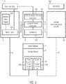
Figure 1 illustrates a configuration of a central safety system, tracker control unit, tracker devices of solar modules and sensors of a solar power plant in accordance with an example of the present invention. -
Figures 2a and 2b illustrate a solar module with a tracker device and tracker control unit wherein the solar module / support means of the tracker device is shown in an operation position (Figure 2a ) and a safety position (Figure 2b ). -
Figure 3 illustrates a configuration of a central safety system of a solar power plant in accordance with an example of the present invention. -
Figure 1 shows an example of a configuration of basic elements of a solar power plant according to the present invention. Twosolar modules 1 each provided with atracker device 2 which is controlled by a respectivetracker control unit 10 are schematically shown. Thetracker control units 10 are connected with a power supply means 3 by power lines a. The power supply means 3 is also connected by a control line b with acentral safety system 4. The power supply means 3 is schematically shown inFigure 1 , and can include a connection to the electrical grid or include a backup power supply, as shown schematically inFigure 3 . - The
central safety system 4 detects an event with one or more sensors. For example, a wind sensor detects high wind speed at the location of thetracker device 2. In the following description of this example, it is assumed that the sensors are air speed meters measuring the wind velocity. Other kinds of sensors can be incorporated in the invention. - If the measured wind speed exceeds some predetermined threshold at a particular location of a section of
tracker devices 2, thecentral safety system 4 interrupts the power supply means 3 to thetracker control units 10 of therespective tracker devices 2 for a predetermined time period and switches on power supply via power supply line a again after the predetermined time period via control line b. The interruption and resumption of power supply via the power supply line a is interpreted at the side of thetracker control unit 10 as a command to move therespective tracker device 2 with the solar module 1 (at the location of which the excessive wind speed was detected by a sensor) into a safety position, i.e., into a horizontal position in this example. - An example for a
solar module 1 and atracker device 2 comprising atracker control unit 10 and a support frame 6 is shown in more detail inFigures 2a and 2b . Thesolar module 1 comprises an array of solar cells and is supported on the support frame 6 comprising vertical and horizontal bars. The frame is mounted by a horizontal beam 7 to a verticalrotatable column 8 that can be driven by an actuator of thetracker device 2. Thetracker device 2 comprises therotatable column 8 that is driven by an actuator (not shown) and a tilting means 9 for appropriately tilting the support frame 6. However, the invention is not limited to this type of tracker device and can be implemented for any type of tracker device, in particular two axes trackers for concentrated photo-voltaics.Figure 2a shows the assembly in an operation state for collecting solar rays and converting solar energy in electric energy. InFigure 2b the same assembly is shown in a horizontal safety position of thesolar module 1 that is adopted by means of the tilting means 9 of thetracker device 2. Thetracker control unit 10 comprises an electrical panel to control thetracker device 2. - Coming back to
Figure 1 it is to be stated that besides the power supply lines a, in principle, no other communication means between thecentral safety system 4 and thetracker control unit 10 for controlling thetracker devices 2 to move the respectivesolar modules 1 into the safety position is needed. However, if desired, optional separate communication lines d can be provided that connect acentral communication system 20 and thetracker control unit 10 with thetracker devices 2 of thesolar modules 1. Thecentral communication system 20 and thecentral safety system 4 communicate via line e. The optional communication lines d and e are schematically represented inFigure 1 by dashed lines. - The communication line e can be used to exchange information between the
central safety system 4 and thecentral communication system 20. For example thecentral communication system 20 can report a particular event which may not be detected by thecentral safety system 4 itself and indicates that thetracker devices 2 have to move into the safety position. - The
central safety system 4 can, on the other side, report to the central communication system what the particular status is and if a dangerous situation is present for thetracker devices 2. Thecentral communication system 4 then can support the action to bring thetracker devices 2 into the safety position. - Both the
central safety system 4 and thecentral communication system 20 can have their respective set of sensors in order to detect different categories of particular events, as for instance wind speed meters for thecentral safety system 4 in order to detect exceeding wind speeds or a sensor connected to thecentral communication system 20 reporting on electrical grid malfunctioning. The communication line e thus enables one to share distinct features and report complementary information to both systems, therefore reliably driving the tracker device into a safety position. However both systems can be connected to the same type of sensors in order to increase the reliability of the positioning system for very sensitive applications. - In a redundant operation mode in addition to the interruption and resumption of power supply, the
central communication system 20 can send explicit commands to thetracker device 2 via the separate communication lines d in order to cause movement ofsolar modules 1 into the safety position, if the wind speed exceeds a predetermined limit at the location of the respectivesolar modules 1. Both operations of sending explicit command signals via the communication line d and interrupting and resuming power supply to thetracker devices 2 via the power supply lines a guarantee a very high level of reliability of the safety positioning operation in case of danger or occurrence of a particular event. -
Figure 3 inter alia shows a configuration of acentral safety system 4 of a solar power plant in accordance with an example of the present invention in some more detail. The showncentral safety system 4 is connected to theelectrical grid 110 and thecentral communication system 20. Thecentral safety system 4 comprises aprogrammable controller 101 for basic communication between components inside thecentral safety system 4 and thecentral communication system 20 via communication line e. Thecentral safety system 4 further comprises at least asensor 102, for instance a wind sensor to detect the wind speed, connected to theprogrammable controller 101. Moreover, an uninterruptible power source (UPS) 103 is connected to theprogrammable controller 101 for providing emergency power to theprogrammable controller 101 in case of a main power breakdown. - The
power supply 3 shown schematically inFigure 3 comprises a connection to theelectrical grid 110 which also provides an electrical connection to thecentral safety system 4. Thepower supply 3 is controlled by theprogrammable controller 101. Additionally, abackup power supply 104, for example, a battery, provides emergency power to the tracker control units, allowing to move the tracker devices with the solar modules into the safety position (for example, horizontal position) in case of a main power breakdown, controlled by theprogrammable controller 101. Thepower supply 3 provides the emergency power from thebackup power supply 104 or the power from the electrical grid to thetracker device 2 and thetracker control unit 10 via power lines a via theswitch gear 106 comprised in thepower supply 3 and controlled by theprogrammable controller 101 via control line b. - The
programmable controller 101 controls via aswitch gear 106 the power supply of tracker control units of respective tracker devices (interruption and resumption as described with reference toFigure 1 ). Thecentral communication system 20 allows for communication to the tracker control units of tracker devices via communication lines d and communication means 109 provided in addition to the power supply lines a as also described with reference toFigure 1 . Thecentral communication system 20 is connected by data lines with at least a sensor 102', for instance a wind sensor, in order to communicate particular events (for example, excessive wind velocities detected by the wind sensor 102') to the central communication system via the communication line e as already explained above. Such a sensor 102' can be different to thesensor 102 comprised in thecentral safety system 4, but is not limited to it, and is shown schematically inFigure 3 . The dashed line f tosensor 102 represents the possibility to use the same set of sensors for thecentral safety system 4 and thecentral communication system 20. - Then switch
gear 106 is used to distribute the power to the tracker control units, as commanded by theprogrammable controller 101 via control line b due to the detection of a particular event. Thecentral communication system 20 and the communication means 109 are used to connect all devices (including the tracker control unit) to a communication network. In standard solar power plants, Ethernet cables and, depending on the size of the CPV Power Plant, also fibre optic cables can be used to realize the communication. However the invention is not limited to these types of realized communication. - The shown
central safety system 4 gets information from sensors, like thewind sensor 102, and from other central components, like thepower supply 3, thebackup power supply 104, the UPS of theprogrammable controller 103 and from thecentral communication system 20. Theses central components may also send status events to theprogrammable controller 101 like an error message coming from thebackup power supply 104 indicating that it has not enough energy to bring the tracker devices into the safety position in case of another upcoming event, like a main power breakdown. Based on this information theprogrammable controller 101 can decide to take thetracker device 2 as a precaution into the safety position and inform the central communication system over the communication line e about the particular event. These kinds of status events can be sent from all central components to theprogrammable controller 101. - Based on these information the
programmable controller 101 steers the different elements like theswitch gear 106 of thepower supply 3 or, in a particular case, thebackup power supply 104 to control thepower supply 108 of thetracker control units 10 which is schematically shown inFigure 3 (interruption and resumption of the power supply to the tracker control unit). - All previously discussed examples are not intended as limitations but serve as examples illustrating features and advantages of the invention. It is to be understood that some or all of the above described features can also be combined in different ways.
Claims (18)
- Method for controlling a tracker device of a solar module of a solar power plant, wherein the solar power plant comprises a central safety system and wherein the tracker device comprises a control unit, an actuator element and a support means for supporting the solar module, comprising the steps of detecting a particular event;
interrupting for a predetermined time period power supply to the control unit of the tracker device in reaction to the detection of the particular event;
resuming power supply after the predetermined time period; and
in reaction to the resumed power supply actuating the support means by the actuator element to move the support means into a predetermined position. - The method according to claim 1, wherein the predetermined position of the support means is a substantially horizontal safety position.
- The method according to claim 1 or 2, wherein the particular event comprises a measured wind velocity exceeding a predetermined threshold.
- The method according to claim 1 or 2, wherein the particular event comprises error messages of other components, in particular the power supply, the backup power supply, or the uninterruptible power source (UPS) of the programmable controller.
- The method according to claim 1, wherein the predetermined position of the support means is a substantially vertical safety position.
- The method according to one of the preceding claims, wherein the step of detecting the particular event is performed by means of one or more sensors, in particular, comprising air speed meters, of the solar power plant.
- The method according to one of the preceding claims, further comprising sending a control signal, in particular, an emergency signal, to the control unit of the tracker device over a communication system comprising a communication line in reaction to the detection of the particular event, wherein the control signal causes the tracker device to move the support means into the predetermined position.
- The method according to one of the preceding claims, comprising repeating the sequence of interrupting power supply to the tracker device for a predetermined time period and resuming power supply after the predetermined time period and wherein the support means is actuated by the actuator element to move it into the predetermined position after the repetition of the sequence.
- The method according to one of the preceding claims, further comprising activating a backup-power supply for supplying power to the tracker device in reaction to the detection of the particular event or in reaction to a detected different event.
- Solar power plant, comprising
at least one solar module mounted on a support means;
a tracker device configured for moving the support means by means of an actuator element and comprising a tracker control unit configured to control the tracker device;
a power supply means configured for supplying power to the tracker device;
at least one sensor configured for detecting a particular event;
a central safety system configured for interrupting the power supply from the power supply means to the control unit of the tracker device for a predetermined time period in reaction to the detection of the particular event and for resuming the power supply to the tracker device after the predetermined time period; and
wherein the tracker device is configured for moving the support means by means of the actuator element to move the support means into a predetermined position in reaction to the resumed power supply. - The solar power plant according to claim 10, comprising
a plurality of solar modules and a plurality of tracker devices each equipped with a control unit; and
a plurality of sensors, in particular, comprising air speed meters, each configured to generate detection data and send the detection data to the central safety system; and wherein
the central safety system is configured to interrupt power supply to particular ones of the control units of the plurality of the tracker devices in reaction to the detection data sent by the plurality of sensors to the central safety system. - The solar power plant according to claim 10 or 11, wherein the predetermined position of the support means is a substantially horizontal safety position.
- The solar power plant according to one of the claims 10 to 12, wherein the particular event comprises a measured wind velocity exceeding a predetermined threshold.
- The solar power plant according to one of the claim 10 or 11, wherein the predetermined position of the support means is a substantially vertical safety position.
- The solar power plant according to one of the claims 10 to 14, further comprising a central communication system comprising a communication line connecting the central communication system and at least one solar module and wherein the central communication system is configured to send a control signal to the tracker device of the at least one solar module over the communication line in reaction to the detection of the particular event that causes the tracker device to move the support means by means of the actuator element into the predetermined position.
- The solar power plant according to one of the claims 10 to 15, further comprising a programmable controller and wherein the at least one sensor, the power supply means, the tracker device and the central safety system can communicate with each other or at least one of the others via the programmable controller.
- The solar power plant according to one of the claims 10 to 15, wherein the central safety system is configured to repeat the sequence of interrupting the power supply from the power supply means to the tracker device for a predetermined time period and resuming the power supply to the control unit of the tracker device after the predetermined time period and wherein the tracker device is configured to move the support means into the predetermined position after the repetition of the sequence.
- The solar power plant according to one of the claims 10 to 17, wherein the at least one solar module comprises concentrator optics.
Applications Claiming Priority (2)
| Application Number | Priority Date | Filing Date | Title |
|---|---|---|---|
| FR1261364A FR2998684B1 (en) | 2012-11-28 | 2012-11-28 | CONTROLLING A SOLAR TRACKING DEVICE |
| PCT/EP2013/073497 WO2014082844A1 (en) | 2012-11-28 | 2013-11-11 | Control of solar tracker device |
Publications (2)
| Publication Number | Publication Date |
|---|---|
| EP2926061A1 EP2926061A1 (en) | 2015-10-07 |
| EP2926061B1 true EP2926061B1 (en) | 2017-10-18 |
Family
ID=47833199
Family Applications (1)
| Application Number | Title | Priority Date | Filing Date |
|---|---|---|---|
| EP13792305.8A Active EP2926061B1 (en) | 2012-11-28 | 2013-11-11 | Control of solar tracker device |
Country Status (7)
| Country | Link |
|---|---|
| US (1) | US10627136B2 (en) |
| EP (1) | EP2926061B1 (en) |
| CN (1) | CN104813116B (en) |
| CA (1) | CA2930646C (en) |
| ES (1) | ES2655550T3 (en) |
| FR (1) | FR2998684B1 (en) |
| WO (1) | WO2014082844A1 (en) |
Families Citing this family (3)
| Publication number | Priority date | Publication date | Assignee | Title |
|---|---|---|---|---|
| MA51799B1 (en) | 2018-02-09 | 2024-01-31 | Sumitomo Electric Industries | SOLAR POWER GENERATION DEVICE AND CONTROL METHOD THEREFOR |
| US11146208B2 (en) * | 2018-04-19 | 2021-10-12 | Electronic Controlled Systems, Inc. | Solar generator |
| US12078979B1 (en) | 2023-07-13 | 2024-09-03 | Array Tech, Inc. | Stowing of photovoltaic (PV) modules in response to weather event forecasts |
Family Cites Families (32)
| Publication number | Priority date | Publication date | Assignee | Title |
|---|---|---|---|---|
| US4256088A (en) * | 1978-09-14 | 1981-03-17 | Acurex Corporation | Solar concentrator utilizing a point focusing solar concentrating panel assembly |
| US4445030A (en) * | 1981-12-31 | 1984-04-24 | Acurex Corporation | Tracking arrangement for a solar energy collecting system |
| US5491463A (en) * | 1993-06-28 | 1996-02-13 | Advanced Control Technologies, Inc. | Power line communication system |
| US5691691A (en) * | 1997-01-06 | 1997-11-25 | Motorola, Inc. | Power-line communication system using pulse transmission on the AC line |
| US6123067A (en) * | 1999-03-31 | 2000-09-26 | Amonix, Inc. | Solar collector tracking system |
| US6688303B2 (en) * | 2001-06-22 | 2004-02-10 | Science Applications International Corporation | Method and system for controlling operation of an energy conversion device |
| US6662801B2 (en) * | 2001-10-02 | 2003-12-16 | Pinnacle West Capital Corporation | Celestial tracking apparatus and method of controlling wind stow therefor |
| JP4002094B2 (en) * | 2001-11-20 | 2007-10-31 | 富士通株式会社 | Semiconductor integrated circuit and method for testing semiconductor integrated circuit |
| JP2004165951A (en) * | 2002-11-13 | 2004-06-10 | Canon Inc | Power line communication control system |
| DE10320722B4 (en) * | 2003-05-08 | 2015-02-19 | Robert Bosch Gmbh | Speed controller with stop function |
| JP4748929B2 (en) * | 2003-08-28 | 2011-08-17 | パナソニック株式会社 | Protection circuit and semiconductor device |
| US7444816B2 (en) * | 2004-12-02 | 2008-11-04 | Wai Man Hon | Solar power station |
| JP2007103713A (en) * | 2005-10-05 | 2007-04-19 | Sharp Corp | Tracking solar power generation system, control method thereof, and control program thereof |
| US20080121525A1 (en) * | 2005-10-11 | 2008-05-29 | Doland George J | Renewable Power Controller for Hydrogen Production |
| DE102007003010B4 (en) * | 2006-01-31 | 2017-02-09 | Sew-Eurodrive Gmbh & Co Kg | Plant, device and method |
| JP4758294B2 (en) * | 2006-07-10 | 2011-08-24 | 株式会社日立製作所 | Area quality information acquisition system |
| JP2009158303A (en) * | 2007-12-26 | 2009-07-16 | Panasonic Electric Works Co Ltd | Outlet, and outlet and outlet plug |
| US20090188488A1 (en) * | 2008-01-28 | 2009-07-30 | Tilt Solar Llc | Wireless mesh networking of solar tracking devices |
| CN101533277A (en) * | 2008-03-10 | 2009-09-16 | 余军 | Solar tracking device based on geographical parameters and method thereof |
| AU2009266870A1 (en) * | 2008-07-03 | 2010-01-07 | Greenfield Solar Corp. | Solar collector assembly |
| US8076625B2 (en) * | 2009-02-25 | 2011-12-13 | Solfocus, Inc. | Field level tracker controller |
| US8254090B2 (en) * | 2009-09-09 | 2012-08-28 | Sundial Power Pods, Llc | Mobile power system |
| ES2661770T3 (en) | 2010-02-25 | 2018-04-03 | Saint-Augustin Canada Electric Inc. | Solar cell set |
| EP2362432B1 (en) | 2010-02-25 | 2017-06-07 | Saint-Augustin Canada Electric Inc. | Solar cell assembly |
| US9964336B2 (en) * | 2010-06-09 | 2018-05-08 | Sunpower Corporation | Method of operating a solar tracking apparatus |
| EP2492966B1 (en) | 2011-02-24 | 2014-09-03 | Soitec Solar GmbH | Solar cell arrays for concentrator photovoltaic modules |
| US8587219B2 (en) * | 2011-03-09 | 2013-11-19 | Enlighted, Inc. | Lighting control with automatic and bypass modes |
| CN103858336B (en) * | 2011-08-15 | 2017-12-08 | 摩根阳光公司 | Self-stabilization equipment for solar tracking |
| US20130048048A1 (en) * | 2011-08-22 | 2013-02-28 | Kent Flanery | System and methods for controlling solar module trackers |
| US20130112237A1 (en) * | 2011-11-08 | 2013-05-09 | Cogenra Solar, Inc. | Photovoltaic-thermal solar energy collector with integrated balance of system |
| US9736911B2 (en) * | 2012-01-17 | 2017-08-15 | Lutron Electronics Co. Inc. | Digital load control system providing power and communication via existing power wiring |
| FR2988909B1 (en) | 2012-04-03 | 2014-12-12 | Soitec Solar Gmbh | PHOTOVOLTAIC MODULE WITH ADJUSTABLE HEIGHT CONCENTRATION |
-
2012
- 2012-11-28 FR FR1261364A patent/FR2998684B1/en active Active
-
2013
- 2013-11-11 ES ES13792305.8T patent/ES2655550T3/en active Active
- 2013-11-11 CA CA2930646A patent/CA2930646C/en active Active
- 2013-11-11 WO PCT/EP2013/073497 patent/WO2014082844A1/en not_active Ceased
- 2013-11-11 EP EP13792305.8A patent/EP2926061B1/en active Active
- 2013-11-11 CN CN201380061878.XA patent/CN104813116B/en active Active
- 2013-11-11 US US14/646,326 patent/US10627136B2/en active Active
Non-Patent Citations (1)
| Title |
|---|
| None * |
Also Published As
| Publication number | Publication date |
|---|---|
| US20150338131A1 (en) | 2015-11-26 |
| CN104813116B (en) | 2018-07-03 |
| CA2930646A1 (en) | 2014-06-05 |
| CA2930646C (en) | 2018-11-06 |
| WO2014082844A1 (en) | 2014-06-05 |
| FR2998684A1 (en) | 2014-05-30 |
| ES2655550T3 (en) | 2018-02-20 |
| CN104813116A (en) | 2015-07-29 |
| FR2998684B1 (en) | 2014-11-21 |
| US10627136B2 (en) | 2020-04-21 |
| EP2926061A1 (en) | 2015-10-07 |
Similar Documents
| Publication | Publication Date | Title |
|---|---|---|
| US8264195B2 (en) | Network topology for monitoring and controlling a solar panel array | |
| CN101970951A (en) | Control systems for solar installations | |
| US9459139B2 (en) | Photovoltaic generating system with control unit for controlling output power conversion and actuation of photovoltaic tracker units | |
| US20090205637A1 (en) | Sun-Tracking Controller for Multiple Solar Collectors | |
| US20130048049A1 (en) | Method and apparatus for controlling photovoltaic plant output using lagging or leading tracking angle | |
| KR101131482B1 (en) | Solar power generation system for high efficient | |
| CN102541089A (en) | Photovoltaic single-axis tracking system based on industrial wireless network and control method | |
| US10627136B2 (en) | Control of solar tracker device | |
| KR100913073B1 (en) | Short-Track Tracking Solar Power and Monitoring Device | |
| JPWO2019082589A1 (en) | Solar power system | |
| CN110764539A (en) | Photovoltaic tracker control system | |
| CN101777856A (en) | Photovoltaic tracking device and network-based monitoring method using poor light sensitivity | |
| US20120132254A1 (en) | Solar tracker device | |
| KR20120125715A (en) | Solar tracking control device with solar cell | |
| CN214591280U (en) | Photovoltaic support governing system | |
| CN102566599A (en) | Synchronously tracking type photovoltaic single-axis tracking system | |
| EP4391364B1 (en) | Solar tracker and control method of the solar tracker | |
| CN102411376A (en) | Photovoltaic support synchronous tracking method adopting direct current bus | |
| AU2020103825A4 (en) | Design for parabolic solar panel control system with wiper | |
| CN203010964U (en) | Heliostat group control device with bottom-layer control function of heliostat | |
| CN121356137A (en) | A photovoltaic tracking power station management system | |
| EP3890183A1 (en) | Solar tracking device intended to be installed in two parallel rows of photovoltaic modules | |
| WO2013033617A2 (en) | Tracker control module | |
| CN117419469A (en) | Heliostat control system and method | |
| CN121386925A (en) | Control system for driving heliostat |
Legal Events
| Date | Code | Title | Description |
|---|---|---|---|
| PUAI | Public reference made under article 153(3) epc to a published international application that has entered the european phase |
Free format text: ORIGINAL CODE: 0009012 |
|
| 17P | Request for examination filed |
Effective date: 20150522 |
|
| AK | Designated contracting states |
Kind code of ref document: A1 Designated state(s): AL AT BE BG CH CY CZ DE DK EE ES FI FR GB GR HR HU IE IS IT LI LT LU LV MC MK MT NL NO PL PT RO RS SE SI SK SM TR |
|
| AX | Request for extension of the european patent |
Extension state: BA ME |
|
| RIN1 | Information on inventor provided before grant (corrected) |
Inventor name: WUELLNER, JOHANNES Inventor name: SENOL, UENVER Inventor name: ZIEGLER, MARTIN |
|
| DAX | Request for extension of the european patent (deleted) | ||
| GRAP | Despatch of communication of intention to grant a patent |
Free format text: ORIGINAL CODE: EPIDOSNIGR1 |
|
| RIC1 | Information provided on ipc code assigned before grant |
Ipc: F24J 2/38 20140101AFI20170321BHEP Ipc: H02S 20/32 20140101ALI20170321BHEP Ipc: H01L 31/042 20140101ALI20170321BHEP Ipc: F24J 2/46 20060101ALI20170321BHEP Ipc: F24J 2/40 20060101ALI20170321BHEP |
|
| INTG | Intention to grant announced |
Effective date: 20170425 |
|
| RAP1 | Party data changed (applicant data changed or rights of an application transferred) |
Owner name: SAINT-AUGUSTIN CANADA ELECTRIC INC. |
|
| GRAS | Grant fee paid |
Free format text: ORIGINAL CODE: EPIDOSNIGR3 |
|
| GRAA | (expected) grant |
Free format text: ORIGINAL CODE: 0009210 |
|
| AK | Designated contracting states |
Kind code of ref document: B1 Designated state(s): AL AT BE BG CH CY CZ DE DK EE ES FI FR GB GR HR HU IE IS IT LI LT LU LV MC MK MT NL NO PL PT RO RS SE SI SK SM TR |
|
| REG | Reference to a national code |
Ref country code: GB Ref legal event code: FG4D |
|
| REG | Reference to a national code |
Ref country code: CH Ref legal event code: EP |
|
| REG | Reference to a national code |
Ref country code: AT Ref legal event code: REF Ref document number: 938317 Country of ref document: AT Kind code of ref document: T Effective date: 20171115 Ref country code: IE Ref legal event code: FG4D |
|
| REG | Reference to a national code |
Ref country code: DE Ref legal event code: R079 Ref document number: 602013028176 Country of ref document: DE Free format text: PREVIOUS MAIN CLASS: F24J0002380000 Ipc: F24S0050200000 |
|
| REG | Reference to a national code |
Ref country code: DE Ref legal event code: R096 Ref document number: 602013028176 Country of ref document: DE Ref country code: FR Ref legal event code: PLFP Year of fee payment: 5 |
|
| REG | Reference to a national code |
Ref country code: ES Ref legal event code: FG2A Ref document number: 2655550 Country of ref document: ES Kind code of ref document: T3 Effective date: 20180220 |
|
| REG | Reference to a national code |
Ref country code: NL Ref legal event code: MP Effective date: 20171018 |
|
| REG | Reference to a national code |
Ref country code: LT Ref legal event code: MG4D |
|
| REG | Reference to a national code |
Ref country code: AT Ref legal event code: MK05 Ref document number: 938317 Country of ref document: AT Kind code of ref document: T Effective date: 20171018 |
|
| PG25 | Lapsed in a contracting state [announced via postgrant information from national office to epo] |
Ref country code: NL Free format text: LAPSE BECAUSE OF FAILURE TO SUBMIT A TRANSLATION OF THE DESCRIPTION OR TO PAY THE FEE WITHIN THE PRESCRIBED TIME-LIMIT Effective date: 20171018 |
|
| PG25 | Lapsed in a contracting state [announced via postgrant information from national office to epo] |
Ref country code: NO Free format text: LAPSE BECAUSE OF FAILURE TO SUBMIT A TRANSLATION OF THE DESCRIPTION OR TO PAY THE FEE WITHIN THE PRESCRIBED TIME-LIMIT Effective date: 20180118 Ref country code: LT Free format text: LAPSE BECAUSE OF FAILURE TO SUBMIT A TRANSLATION OF THE DESCRIPTION OR TO PAY THE FEE WITHIN THE PRESCRIBED TIME-LIMIT Effective date: 20171018 Ref country code: SE Free format text: LAPSE BECAUSE OF FAILURE TO SUBMIT A TRANSLATION OF THE DESCRIPTION OR TO PAY THE FEE WITHIN THE PRESCRIBED TIME-LIMIT Effective date: 20171018 Ref country code: FI Free format text: LAPSE BECAUSE OF FAILURE TO SUBMIT A TRANSLATION OF THE DESCRIPTION OR TO PAY THE FEE WITHIN THE PRESCRIBED TIME-LIMIT Effective date: 20171018 |
|
| PG25 | Lapsed in a contracting state [announced via postgrant information from national office to epo] |
Ref country code: IS Free format text: LAPSE BECAUSE OF FAILURE TO SUBMIT A TRANSLATION OF THE DESCRIPTION OR TO PAY THE FEE WITHIN THE PRESCRIBED TIME-LIMIT Effective date: 20180218 Ref country code: LV Free format text: LAPSE BECAUSE OF FAILURE TO SUBMIT A TRANSLATION OF THE DESCRIPTION OR TO PAY THE FEE WITHIN THE PRESCRIBED TIME-LIMIT Effective date: 20171018 Ref country code: AT Free format text: LAPSE BECAUSE OF FAILURE TO SUBMIT A TRANSLATION OF THE DESCRIPTION OR TO PAY THE FEE WITHIN THE PRESCRIBED TIME-LIMIT Effective date: 20171018 Ref country code: HR Free format text: LAPSE BECAUSE OF FAILURE TO SUBMIT A TRANSLATION OF THE DESCRIPTION OR TO PAY THE FEE WITHIN THE PRESCRIBED TIME-LIMIT Effective date: 20171018 Ref country code: RS Free format text: LAPSE BECAUSE OF FAILURE TO SUBMIT A TRANSLATION OF THE DESCRIPTION OR TO PAY THE FEE WITHIN THE PRESCRIBED TIME-LIMIT Effective date: 20171018 Ref country code: BG Free format text: LAPSE BECAUSE OF FAILURE TO SUBMIT A TRANSLATION OF THE DESCRIPTION OR TO PAY THE FEE WITHIN THE PRESCRIBED TIME-LIMIT Effective date: 20180118 Ref country code: GR Free format text: LAPSE BECAUSE OF FAILURE TO SUBMIT A TRANSLATION OF THE DESCRIPTION OR TO PAY THE FEE WITHIN THE PRESCRIBED TIME-LIMIT Effective date: 20180119 |
|
| REG | Reference to a national code |
Ref country code: DE Ref legal event code: R097 Ref document number: 602013028176 Country of ref document: DE |
|
| PG25 | Lapsed in a contracting state [announced via postgrant information from national office to epo] |
Ref country code: SK Free format text: LAPSE BECAUSE OF FAILURE TO SUBMIT A TRANSLATION OF THE DESCRIPTION OR TO PAY THE FEE WITHIN THE PRESCRIBED TIME-LIMIT Effective date: 20171018 Ref country code: CZ Free format text: LAPSE BECAUSE OF FAILURE TO SUBMIT A TRANSLATION OF THE DESCRIPTION OR TO PAY THE FEE WITHIN THE PRESCRIBED TIME-LIMIT Effective date: 20171018 Ref country code: EE Free format text: LAPSE BECAUSE OF FAILURE TO SUBMIT A TRANSLATION OF THE DESCRIPTION OR TO PAY THE FEE WITHIN THE PRESCRIBED TIME-LIMIT Effective date: 20171018 Ref country code: DK Free format text: LAPSE BECAUSE OF FAILURE TO SUBMIT A TRANSLATION OF THE DESCRIPTION OR TO PAY THE FEE WITHIN THE PRESCRIBED TIME-LIMIT Effective date: 20171018 Ref country code: CH Free format text: LAPSE BECAUSE OF NON-PAYMENT OF DUE FEES Effective date: 20171130 Ref country code: LI Free format text: LAPSE BECAUSE OF NON-PAYMENT OF DUE FEES Effective date: 20171130 Ref country code: MC Free format text: LAPSE BECAUSE OF FAILURE TO SUBMIT A TRANSLATION OF THE DESCRIPTION OR TO PAY THE FEE WITHIN THE PRESCRIBED TIME-LIMIT Effective date: 20171018 |
|
| PLBE | No opposition filed within time limit |
Free format text: ORIGINAL CODE: 0009261 |
|
| STAA | Information on the status of an ep patent application or granted ep patent |
Free format text: STATUS: NO OPPOSITION FILED WITHIN TIME LIMIT |
|
| PG25 | Lapsed in a contracting state [announced via postgrant information from national office to epo] |
Ref country code: LU Free format text: LAPSE BECAUSE OF NON-PAYMENT OF DUE FEES Effective date: 20171111 Ref country code: RO Free format text: LAPSE BECAUSE OF FAILURE TO SUBMIT A TRANSLATION OF THE DESCRIPTION OR TO PAY THE FEE WITHIN THE PRESCRIBED TIME-LIMIT Effective date: 20171018 Ref country code: SM Free format text: LAPSE BECAUSE OF FAILURE TO SUBMIT A TRANSLATION OF THE DESCRIPTION OR TO PAY THE FEE WITHIN THE PRESCRIBED TIME-LIMIT Effective date: 20171018 Ref country code: PL Free format text: LAPSE BECAUSE OF FAILURE TO SUBMIT A TRANSLATION OF THE DESCRIPTION OR TO PAY THE FEE WITHIN THE PRESCRIBED TIME-LIMIT Effective date: 20171018 |
|
| REG | Reference to a national code |
Ref country code: BE Ref legal event code: MM Effective date: 20171130 |
|
| REG | Reference to a national code |
Ref country code: IE Ref legal event code: MM4A |
|
| 26N | No opposition filed |
Effective date: 20180719 |
|
| GBPC | Gb: european patent ceased through non-payment of renewal fee |
Effective date: 20180118 |
|
| PG25 | Lapsed in a contracting state [announced via postgrant information from national office to epo] |
Ref country code: MT Free format text: LAPSE BECAUSE OF NON-PAYMENT OF DUE FEES Effective date: 20171111 |
|
| PG25 | Lapsed in a contracting state [announced via postgrant information from national office to epo] |
Ref country code: IE Free format text: LAPSE BECAUSE OF NON-PAYMENT OF DUE FEES Effective date: 20171111 |
|
| PG25 | Lapsed in a contracting state [announced via postgrant information from national office to epo] |
Ref country code: GB Free format text: LAPSE BECAUSE OF NON-PAYMENT OF DUE FEES Effective date: 20180118 Ref country code: BE Free format text: LAPSE BECAUSE OF NON-PAYMENT OF DUE FEES Effective date: 20171130 Ref country code: SI Free format text: LAPSE BECAUSE OF FAILURE TO SUBMIT A TRANSLATION OF THE DESCRIPTION OR TO PAY THE FEE WITHIN THE PRESCRIBED TIME-LIMIT Effective date: 20171018 |
|
| PG25 | Lapsed in a contracting state [announced via postgrant information from national office to epo] |
Ref country code: HU Free format text: LAPSE BECAUSE OF FAILURE TO SUBMIT A TRANSLATION OF THE DESCRIPTION OR TO PAY THE FEE WITHIN THE PRESCRIBED TIME-LIMIT; INVALID AB INITIO Effective date: 20131111 |
|
| PG25 | Lapsed in a contracting state [announced via postgrant information from national office to epo] |
Ref country code: CY Free format text: LAPSE BECAUSE OF FAILURE TO SUBMIT A TRANSLATION OF THE DESCRIPTION OR TO PAY THE FEE WITHIN THE PRESCRIBED TIME-LIMIT Effective date: 20171018 |
|
| PG25 | Lapsed in a contracting state [announced via postgrant information from national office to epo] |
Ref country code: MK Free format text: LAPSE BECAUSE OF FAILURE TO SUBMIT A TRANSLATION OF THE DESCRIPTION OR TO PAY THE FEE WITHIN THE PRESCRIBED TIME-LIMIT Effective date: 20171018 |
|
| PG25 | Lapsed in a contracting state [announced via postgrant information from national office to epo] |
Ref country code: TR Free format text: LAPSE BECAUSE OF FAILURE TO SUBMIT A TRANSLATION OF THE DESCRIPTION OR TO PAY THE FEE WITHIN THE PRESCRIBED TIME-LIMIT Effective date: 20171018 |
|
| PG25 | Lapsed in a contracting state [announced via postgrant information from national office to epo] |
Ref country code: PT Free format text: LAPSE BECAUSE OF FAILURE TO SUBMIT A TRANSLATION OF THE DESCRIPTION OR TO PAY THE FEE WITHIN THE PRESCRIBED TIME-LIMIT Effective date: 20171018 |
|
| PG25 | Lapsed in a contracting state [announced via postgrant information from national office to epo] |
Ref country code: AL Free format text: LAPSE BECAUSE OF FAILURE TO SUBMIT A TRANSLATION OF THE DESCRIPTION OR TO PAY THE FEE WITHIN THE PRESCRIBED TIME-LIMIT Effective date: 20171018 |
|
| PGFP | Annual fee paid to national office [announced via postgrant information from national office to epo] |
Ref country code: ES Payment date: 20231201 Year of fee payment: 11 |
|
| PGFP | Annual fee paid to national office [announced via postgrant information from national office to epo] |
Ref country code: IT Payment date: 20231130 Year of fee payment: 11 Ref country code: DE Payment date: 20231129 Year of fee payment: 11 |
|
| PGFP | Annual fee paid to national office [announced via postgrant information from national office to epo] |
Ref country code: FR Payment date: 20241127 Year of fee payment: 12 |
|
| REG | Reference to a national code |
Ref country code: DE Ref legal event code: R119 Ref document number: 602013028176 Country of ref document: DE |
|
| PG25 | Lapsed in a contracting state [announced via postgrant information from national office to epo] |
Ref country code: DE Free format text: LAPSE BECAUSE OF NON-PAYMENT OF DUE FEES Effective date: 20250603 |
|
| PG25 | Lapsed in a contracting state [announced via postgrant information from national office to epo] |
Ref country code: IT Free format text: LAPSE BECAUSE OF NON-PAYMENT OF DUE FEES Effective date: 20241111 |
|
| REG | Reference to a national code |
Ref country code: ES Ref legal event code: FD2A Effective date: 20260102 |
|
| PG25 | Lapsed in a contracting state [announced via postgrant information from national office to epo] |
Ref country code: ES Free format text: LAPSE BECAUSE OF NON-PAYMENT OF DUE FEES Effective date: 20241112 |