EP2925493B1 - Teleoperation of machines having at least one actuated mechanism and a fault detection and recovery system - Google Patents
Teleoperation of machines having at least one actuated mechanism and a fault detection and recovery system Download PDFInfo
- Publication number
- EP2925493B1 EP2925493B1 EP13811307.1A EP13811307A EP2925493B1 EP 2925493 B1 EP2925493 B1 EP 2925493B1 EP 13811307 A EP13811307 A EP 13811307A EP 2925493 B1 EP2925493 B1 EP 2925493B1
- Authority
- EP
- European Patent Office
- Prior art keywords
- machine
- fault
- robot
- control station
- recovery
- Prior art date
- Legal status (The legal status is an assumption and is not a legal conclusion. Google has not performed a legal analysis and makes no representation as to the accuracy of the status listed.)
- Active
Links
Images


Classifications
-
- B—PERFORMING OPERATIONS; TRANSPORTING
- B25—HAND TOOLS; PORTABLE POWER-DRIVEN TOOLS; MANIPULATORS
- B25J—MANIPULATORS; CHAMBERS PROVIDED WITH MANIPULATION DEVICES
- B25J9/00—Program-controlled manipulators
- B25J9/16—Program controls
- B25J9/1679—Program controls characterised by the tasks executed
- B25J9/1689—Teleoperation
-
- G—PHYSICS
- G05—CONTROLLING; REGULATING
- G05B—CONTROL OR REGULATING SYSTEMS IN GENERAL; FUNCTIONAL ELEMENTS OF SUCH SYSTEMS; MONITORING OR TESTING ARRANGEMENTS FOR SUCH SYSTEMS OR ELEMENTS
- G05B2219/00—Program-control systems
- G05B2219/30—Nc systems
- G05B2219/40—Robotics, robotics mapping to robotics vision
- G05B2219/40195—Tele-operation, computer assisted manual operation
-
- G—PHYSICS
- G05—CONTROLLING; REGULATING
- G05B—CONTROL OR REGULATING SYSTEMS IN GENERAL; FUNCTIONAL ELEMENTS OF SUCH SYSTEMS; MONITORING OR TESTING ARRANGEMENTS FOR SUCH SYSTEMS OR ELEMENTS
- G05B2219/00—Program-control systems
- G05B2219/30—Nc systems
- G05B2219/40—Robotics, robotics mapping to robotics vision
- G05B2219/40204—Each fault condition has a different recovery procedure
-
- Y—GENERAL TAGGING OF NEW TECHNOLOGICAL DEVELOPMENTS; GENERAL TAGGING OF CROSS-SECTIONAL TECHNOLOGIES SPANNING OVER SEVERAL SECTIONS OF THE IPC; TECHNICAL SUBJECTS COVERED BY FORMER USPC CROSS-REFERENCE ART COLLECTIONS [XRACs] AND DIGESTS
- Y10—TECHNICAL SUBJECTS COVERED BY FORMER USPC
- Y10S—TECHNICAL SUBJECTS COVERED BY FORMER USPC CROSS-REFERENCE ART COLLECTIONS [XRACs] AND DIGESTS
- Y10S901/00—Robots
- Y10S901/02—Arm motion controller
- Y10S901/09—Closed loop, sensor feedback controls arm movement
-
- Y—GENERAL TAGGING OF NEW TECHNOLOGICAL DEVELOPMENTS; GENERAL TAGGING OF CROSS-SECTIONAL TECHNOLOGIES SPANNING OVER SEVERAL SECTIONS OF THE IPC; TECHNICAL SUBJECTS COVERED BY FORMER USPC CROSS-REFERENCE ART COLLECTIONS [XRACs] AND DIGESTS
- Y10—TECHNICAL SUBJECTS COVERED BY FORMER USPC
- Y10S—TECHNICAL SUBJECTS COVERED BY FORMER USPC CROSS-REFERENCE ART COLLECTIONS [XRACs] AND DIGESTS
- Y10S901/00—Robots
- Y10S901/46—Sensing device
Definitions
- This invention relates to the teleoperation of one or more robots or other machines with at least one actuated mechanism.
- Teleoperation of an industrial robot occurs when the operator of the teleoperated industrial robot is located apart from the robot when the industrial robot performs work.
- An industrial robot is an automatically controlled, reprogrammable, multipurpose manipulator programmable in three or more axes. Examples of industrial robots are robots located at a fixed position that are mobile by themselves or mobile because the robot is mounted on a device that it is itself mobile such as a motorized vehicle or mounted on a track or gantry etc.
- located apart from each other is meant that the operator and teleoperated industrial robot are either within the line of sight of each other or are separated from each other by a barrier through which the operator can see the robot that is controlled by the operator, or are at a distance from each other such that the operator cannot see the robot with his or her eyes. If there is a see through barrier, the barrier separates the operator from work performed by the robot that is hazardous to the health or safety of the operator.
- the principal applications for teleoperated industrial robots are machining, handling of hazardous materials, assembling/disassembling, operation in a contaminated environment, inspection and service, or other operations in an unmanned, harsh outdoor environment such as offshore, desert, Arctic, Antarctic, subsea and space.
- FR2957000A1 discloses a system for remote handling of a manipulator arm placed in a working scene.
- the system includes an operating cell having at least one operator who interacts remotely with the working scene by means of a master arm.
- the system monitors collisions of the manipulator arm by means of virtual simulations of physical phenomena.
- a dynamic fault tolerance framework for remote robots discloses a multilayered control framework able to detect faults in a remote robot and provide, by means of specific algorithms, fault tolerance for the robot so that the robot can continue its operating state even in presence of a fault.
- the article having title "Fault-tolerant teleoperation systems design” discloses fault tolerant systems and control methods designed to complete the task of a teleoperated robot even where there is a failure in one of its components.
- US2006161303A1 discloses a remote controlled robot system that includes a robot and a remote control station.
- a user can control movement of the robot from the remote control station.
- the robot has a camera that generates video images that are transmitted to the remote control station through a network.
- the user can control movement of the robot while viewing the video images provided by the robot camera.
- the robot can automatically stop movement if it does not receive a robot control command within a time interval.
- the system comprises:
- a system 10 that has at least one remote robot station 12, at least one operator station 14 and at least one communication link 16 between the robot station 12 and the operator station 14.
- the physical distance between the remote robot station 12 and the operator station 14 can vary from "next door” to each other to "another continent”.
- the robot station 12 includes at least one robot 12a.
- Robot 12a is for example a six degree of freedom industrial robot available from ABB.
- Robot station 12 also includes a robot controller 12b that includes a data interface which accepts motion commands and provides actual motion data, and optionally one or more remote sensor devices 12c that observe the robot station 12 and attached processes, such as cameras, microphones, position sensors, proximity sensors and force sensors.
- the sensor devices 12c may either be smart sensors, that is, the sensor device 12c includes data processing capability or not smart sensors, that is, the sensor device 12c does not include data processing capability.
- the output of the sensor devices is connected directly to robot controller 12b. If the sensor devices 12c are not smart sensors, then their output can be connected either to a computation device 17 to process the sensor device output or to the communication link 16 described in more detail below so that the sensor device output is processed in data processing device 14c.
- the robot station 12 can also include as an option one or more actuators and other devices (not shown in Fig. 1 but well known to those of ordinary skill in this art), that are mounted to the robot or next to the robot, such as grippers, fixtures, welding guns, spraying guns, spotlights and conveyors.
- actuators and other devices not shown in Fig. 1 but well known to those of ordinary skill in this art
- the controller 12b has the program which when executed controls the motion of the robot 12a to perform work.
- the robot may hold a tool, not shown, which is used to perform work on a stationary or moving workpiece, not shown, or may hold the workpiece which has work performed on it by an appropriate tool.
- the remote sensor devices 12c provide input signals to the controller 12b that the controller uses to control the robot 12a in performance of the work.
- the operator station 14 has at least one teleoperation input device 14a such as joysticks or stylus-type devices which the operator uses to create continuous motion signals (position or speed signals). When force feedback is added to these devices they become haptic devices. This feedback causes a vibration in the joystick and the operator feels the force feedback in the stylus-type devices.
- teleoperation input device 14a such as joysticks or stylus-type devices which the operator uses to create continuous motion signals (position or speed signals).
- the signals from these input devices 14a are used by the controller 12b to operate the robot 12a.
- the device side also has at least one display device 14b and a data processing device 14c which is connected to both the input devices 14a and the display devices 14b.
- the monitoring (display) device 14b shows actual data about the robot motion and attached processes, for example, camera images, acoustic feedback and sensor values.
- the data processing device 14c processes data in both directions.
- Device 14c may for example be an industrial PC or a PLC.
- the operator station 14 may also include a safety enable device (not shown in Fig. 1 ) that is separate and distinct from input devices 14a and may for example be a three position switch.
- the safety enabling device enables and disables power to the robot 12a and attached processes.
- the communication link 16 connects the robot controller 12b and the data processing device 14c to each other.
- the communication link 16 comprises one or more communication links 16-1 to 16-N.
- the communication link 16 between the operator station 14 and the robot station 12 may be realized with various technologies (e.g. fiber-optic/radio/cable on different types and layers of data protocols).
- a major portion or the entire infrastructure of the communication link may already exist and be used for other purposes than teleoperating robots.
- Typical examples are existing Ethernet installations with LAN and WLAN, Bluetooth, ZigBee and other wireless industrial links, point-to-point radio systems or laser-optical systems, and satellite communication links.
- System 10 is operated to maintain a reliable "real-time" communication link 16 between device side 14 and the remotely located robot side 12.
- the system 10 changes parameters of the communication link 16 and the robot motion, depending on the current available data rate and/or transmission time of the communication link 16.
- the operator has direct remote control of the motion of robot 12a and attached processes.
- real-time as used herein is in the context of teleoperation of the motion of a robot 12a or a machine.
- the teleoperation is considered to be real-time if:
- Exceeding the maximum delay may result in damage to the workpiece or to the robot or other equipment on the robot side.
- the teleoperated robotic is used in a grinding application and the communication delay exceeds the maximum delay, this causes the operator to remove more material from the workpiece than desired. This excess removal of material can result in damage to the workpiece.
- the communication delay exceeding the maximum delay causes the collision between the robot 12a and other equipment on robot side.
- a fault such as a collision, communication failure or a dangerous robot movement may occur during the operation of a teleoperated robot.
- the robot is stopped immediately upon the occurrence of the fault by an emergency stop (E-stop) mechanism.
- This mechanism stops the robot movement by mechanical braking systems and cuts off power to the robot motors.
- the E-stop makes recovery difficult and inconvenient to the operator of the teleoperated robot as the operator cannot access the teleoperated robot due to the distance between the operator and the robot or the hazardous environment in which the teleoperated robot is used.
- Fig. 2 illustrates the robot teleoperation system 10 in a manner similar to that shown in Fig. 1 with the added elements described herein.
- An element in Fig. 2 that is identical to the same element shown in Fig. 1 has the reference numeral used for that element in Fig. 1 .
- the display 14b and the data processing device 14c shown in Fig. 1 are not shown in Fig. 2 .
- System 10 has a robot 12a that resides in a remotely located robot station 12 with a tool 12d held by robot 12a and sensors 12c that are on and surround the robot 12.
- a controlling input device 14a in the operator station 14 is connected with the robot 12a through wire or wireless communication such as communication link 16 of Fig. 1 .
- An operator 14d operates the device 14a and looks either at a monitor 14b (see Fig. 1 ) to observe the robot 12a from a distance or through a barrier 18 that is between the robot 12a and the controlling input device 14a.
- controller 12b of Fig. 1 While not shown in Fig. 2 , there is a controller such as controller 12b of Fig. 1 that is associated with robot 12a.
- the controller 12b is a computing device connected to the robot 12a that is programmed to respond to commands from the controlling input device 14a to use the tool 12d to perform a predetermined operation.
- a robot program such as RAPID available from ABB is running in the background in the robot controller 12b to monitor the robot motion through various sensors on and around the robot 12a.
- the robot program receives the fault status information from the sensors, informs the operator 14d at the controlling device 14 and asks for the recovery command.
- the operator 14d selects a specific fault handling and recovery procedure to be used and issues the recovery command.
- the robot 12a follows the predetermined rules that reside in the robot controller 12b and starts the automatic fault recovery procedure.
- Fig. 5 shows the flowchart 500 for the robot fault detection and recovery system process.
- data about a possible fault that has been detected is received by the robot program.
- the robot program determines from the received data if there is an actual fault. If the answer is no, the program returns back to block 502. If the answer is yes, the program proceeds to block 506 where the information from the sensors is read and the program determines from that information the fault types. The information about the fault types is sent to the operator and at block 508 the operator selects the recovery procedure and issues the recovery command for that procedure.
- predefined rules for recovering from a fault There are as shown in block 510 stored predefined rules for recovering from a fault.
- the rules ensure that the recovery from the fault meets the safety requirements for the operation of the robot.
- the recovery process is started using the predefined rules and the issued recovery command.
- the operator 14d on the device side 14 can monitor the progress and status of the recovery using the sensor data obtained from the robot side 12. If the operator 14d determines that the automatic recovery process is not going as expected, that is, the system is not recovering, the operator 14d can interfere to alter the recovery process to a desired recovery. However, once started, the robot recovery process can be performed independently without operator interference.
- the robot 12a has to conduct the recovery by itself based on predefined rules stored in the robot controller 12b. For example, the robot 12a could retreat from its current task and return to home in a safe way or stay at the current position (status) awaiting further commands from the controlling device 14a after the communication is resumed.
- the controlling device 12b When the system is recovered from a fault on the robot side 12, the controlling device 12b is informed and starts its own recovery process.
- the robot program (RAPID) recovery procedure is also used in the device side fault recovery.
- Fig. 6 shows a flowchart 600 for the robot fault detection and recovery system process.
- the device side has received the information from the robot side that the recovery has occurred at the robot side.
- the recovery at the device side is initiated based on the information from the robot side and the predefined rules 606.
- Decision 608 asks if the device side recovery is finished. If not, the flow returns back to block 604. If it has, the flow proceeds to block 610 where the recovery at the device side is synchronized with the recovery at the robot side.
Landscapes
- Engineering & Computer Science (AREA)
- Robotics (AREA)
- Mechanical Engineering (AREA)
- Manipulator (AREA)
- Numerical Control (AREA)
Description
- This invention relates to the teleoperation of one or more robots or other machines with at least one actuated mechanism.
- Teleoperation of an industrial robot occurs when the operator of the teleoperated industrial robot is located apart from the robot when the industrial robot performs work. An industrial robot is an automatically controlled, reprogrammable, multipurpose manipulator programmable in three or more axes. Examples of industrial robots are robots located at a fixed position that are mobile by themselves or mobile because the robot is mounted on a device that it is itself mobile such as a motorized vehicle or mounted on a track or gantry etc.
- By located apart from each other is meant that the operator and teleoperated industrial robot are either within the line of sight of each other or are separated from each other by a barrier through which the operator can see the robot that is controlled by the operator, or are at a distance from each other such that the operator cannot see the robot with his or her eyes. If there is a see through barrier, the barrier separates the operator from work performed by the robot that is hazardous to the health or safety of the operator.
- The principal applications for teleoperated industrial robots are machining, handling of hazardous materials, assembling/disassembling, operation in a contaminated environment, inspection and service, or other operations in an unmanned, harsh outdoor environment such as offshore, desert, Arctic, Antarctic, subsea and space.
-
FR2957000A1
The article having title "A dynamic fault tolerance framework for remote robots" discloses a multilayered control framework able to detect faults in a remote robot and provide, by means of specific algorithms, fault tolerance for the robot so that the robot can continue its operating state even in presence of a fault.
The article having title "Fault-tolerant teleoperation systems design" discloses fault tolerant systems and control methods designed to complete the task of a teleoperated robot even where there is a failure in one of its components.
US2006161303A1 discloses a remote controlled robot system that includes a robot and a remote control station. A user can control movement of the robot from the remote control station. The robot has a camera that generates video images that are transmitted to the remote control station through a network. The user can control movement of the robot while viewing the video images provided by the robot camera. The robot can automatically stop movement if it does not receive a robot control command within a time interval. - A system for teleoperation of a machine having at least one actuated mechanism and a predetermined number of degrees of freedom. The system comprises:
- a control station remotely located from a location of the machine, the machine controlled from the control station to perform a predetermined function;
- a two way real-time communication link between the machine and the remotely located control station; and
- a controller at the machine location having therein program code, the program code configured to determine from data from one or more sensors at the machine location if an actual fault has occurred in the machine when the machine is performing the predetermined function, the program code further configured to determine from the sensor data when an actual fault has occurred, one or more types for the fault and transmit the one or more fault types to the control station for analysis at the control station. The system further comprising predefined rules for recovering from a machine fault, said predefined rules stored in said controller at said machine location, said controller starting said recovery from said machine fault using said predefined rules for recovering from a machine fault and said recovery procedure transmitted to said machine location from said control station.
-
-
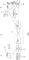
Fig. 1 shows an embodiment for a system for a teleoperated industrial robot. -
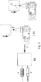
Fig. 2 shows an embodiment for the system ofFig. 1 which also shows an obstacle or a distance between the teleoperator and the robot. -
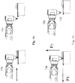
Fig 3 shows a drawing for the safe stop and reduce contact force routine. -
Fig. 4a shows a drawing for the safe stop and release contact force routine. -
Fig. 4b shows the routine ofFig. 6a the automatic retraction of the tool along the contact force direction. -
Fig. 5 shows a flowchart for the robot fault detection and recovery system process. -
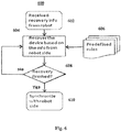
Fig. 6 shows a flowchart for the robot fault detection and recovery system process. - Referring now to
Fig. 1 , there is shown asystem 10 that has at least oneremote robot station 12, at least oneoperator station 14 and at least onecommunication link 16 between therobot station 12 and theoperator station 14. The physical distance between theremote robot station 12 and theoperator station 14 can vary from "next door" to each other to "another continent". - The
robot station 12 includes at least onerobot 12a. Robot 12a is for example a six degree of freedom industrial robot available from ABB. -
Robot station 12 also includes a robot controller 12b that includes a data interface which accepts motion commands and provides actual motion data, and optionally one or more remote sensor devices 12c that observe therobot station 12 and attached processes, such as cameras, microphones, position sensors, proximity sensors and force sensors. The sensor devices 12c may either be smart sensors, that is, the sensor device 12c includes data processing capability or not smart sensors, that is, the sensor device 12c does not include data processing capability. - If the sensor devices 12c are smart sensors then the output of the sensor devices is connected directly to robot controller 12b. If the sensor devices 12c are not smart sensors, then their output can be connected either to a computation device 17 to process the sensor device output or to the
communication link 16 described in more detail below so that the sensor device output is processed indata processing device 14c. - The
robot station 12 can also include as an option one or more actuators and other devices (not shown inFig. 1 but well known to those of ordinary skill in this art), that are mounted to the robot or next to the robot, such as grippers, fixtures, welding guns, spraying guns, spotlights and conveyors. - The controller 12b has the program which when executed controls the motion of the
robot 12a to perform work. As is well known, the robot may hold a tool, not shown, which is used to perform work on a stationary or moving workpiece, not shown, or may hold the workpiece which has work performed on it by an appropriate tool. The remote sensor devices 12c provide input signals to the controller 12b that the controller uses to control therobot 12a in performance of the work. - The
operator station 14 has at least oneteleoperation input device 14a such as joysticks or stylus-type devices which the operator uses to create continuous motion signals (position or speed signals). When force feedback is added to these devices they become haptic devices. This feedback causes a vibration in the joystick and the operator feels the force feedback in the stylus-type devices. - The signals from these
input devices 14a are used by the controller 12b to operate therobot 12a. The device side also has at least one display device 14b and adata processing device 14c which is connected to both theinput devices 14a and the display devices 14b. - The monitoring (display) device 14b shows actual data about the robot motion and attached processes, for example, camera images, acoustic feedback and sensor values. The
data processing device 14c processes data in both directions.Device 14c may for example be an industrial PC or a PLC. - The
operator station 14 may also include a safety enable device (not shown inFig. 1 ) that is separate and distinct frominput devices 14a and may for example be a three position switch. The safety enabling device enables and disables power to therobot 12a and attached processes. - The
communication link 16 connects the robot controller 12b and thedata processing device 14c to each other. Thecommunication link 16 comprises one or more communication links 16-1 to 16-N. - The
communication link 16 between theoperator station 14 and therobot station 12 may be realized with various technologies (e.g. fiber-optic/radio/cable on different types and layers of data protocols). A major portion or the entire infrastructure of the communication link may already exist and be used for other purposes than teleoperating robots. Typical examples are existing Ethernet installations with LAN and WLAN, Bluetooth, ZigBee and other wireless industrial links, point-to-point radio systems or laser-optical systems, and satellite communication links. -
System 10 is operated to maintain a reliable "real-time"communication link 16 betweendevice side 14 and the remotely locatedrobot side 12. Thesystem 10 changes parameters of thecommunication link 16 and the robot motion, depending on the current available data rate and/or transmission time of thecommunication link 16. - In
system 10, the operator has direct remote control of the motion ofrobot 12a and attached processes. Thus the term "real-time" as used herein is in the context of teleoperation of the motion of arobot 12a or a machine. The teleoperation is considered to be real-time if: - a maximum delay between operator commands, robot motion, and feedback about robot motion and attached processes at the operator station is not exceeded, and
- the maximum delay is dependent on the speed of machine motion, i.e. with slow machine motion a slightly longer delay is acceptable, and
- the maximum delay is deterministic, i.e. the delay time does not significantly vary over time.
- Exceeding the maximum delay may result in damage to the workpiece or to the robot or other equipment on the robot side. For example, if the teleoperated robotic is used in a grinding application and the communication delay exceeds the maximum delay, this causes the operator to remove more material from the workpiece than desired. This excess removal of material can result in damage to the workpiece. Also for example, if the teleoperated robot is used in a material handling application, the communication delay exceeding the maximum delay causes the collision between the
robot 12a and other equipment on robot side. - This understanding of "real-time" is similar to real-time computation, where not only wrong results of logic and arithmetic operations can occur but also not timely results cause errors.
- A fault such as a collision, communication failure or a dangerous robot movement may occur during the operation of a teleoperated robot. Traditionally the robot is stopped immediately upon the occurrence of the fault by an emergency stop (E-stop) mechanism. This mechanism stops the robot movement by mechanical braking systems and cuts off power to the robot motors. However, the E-stop makes recovery difficult and inconvenient to the operator of the teleoperated robot as the operator cannot access the teleoperated robot due to the distance between the operator and the robot or the hazardous environment in which the teleoperated robot is used.
-
Fig. 2 illustrates therobot teleoperation system 10 in a manner similar to that shown inFig. 1 with the added elements described herein. An element inFig. 2 that is identical to the same element shown inFig. 1 has the reference numeral used for that element inFig. 1 . For ease of illustration, the display 14b and thedata processing device 14c shown inFig. 1 are not shown inFig. 2 . -
System 10 has arobot 12a that resides in a remotely locatedrobot station 12 with atool 12d held byrobot 12a and sensors 12c that are on and surround therobot 12. A controllinginput device 14a in theoperator station 14 is connected with therobot 12a through wire or wireless communication such as communication link 16 ofFig. 1 . An operator 14d operates thedevice 14a and looks either at a monitor 14b (seeFig. 1 ) to observe therobot 12a from a distance or through abarrier 18 that is between therobot 12a and thecontrolling input device 14a. - While not shown in
Fig. 2 , there is a controller such as controller 12b ofFig. 1 that is associated withrobot 12a. The controller 12b is a computing device connected to therobot 12a that is programmed to respond to commands from the controllinginput device 14a to use thetool 12d to perform a predetermined operation. - The error handling features of
system 10 are as follows: - 1) When an error occurs, an application specific user programmable trap routine written in robot program language is automatically executed. There is no need for any human intervention. The trap routine can handle application specific requirements such as for example turning off a spindle.
- 2) The trap routine is invoked automatically when a teleoperation supervision error is generated by the robot controller 12b. For example, the trap routine is automatically invoked when there is a loss of communication or the robot speed limit is exceeded.
- 3) A default trap routine is provided if an application specific trap routine is not provided by a programmer for the user of the
robot 12a. - 4) When a teleoperation error occurs, the
robot 12a can take some standard recovery actions in addition to the application specific actions such as reducing the robot position gain so that therobot 12a is soft and can backtrack along the path or contact force direction to reduce contact. These actions can be put in the trap routine. A soft robot has a reduced stiffness and this means that less contact force is needed to cause therobot 12a to move a given distance.
Several examples of a safe stop routine are as follows:- Safe stop and reduce contact force routine: This routine is a controlled stop with power available to the motors to achieve the stop for all contact teleoperation applications. The robot position at stop acts as a reference position and the stiffness parameters A and B, shown in
Fig. 3 , in the robot controller 12b are decreased, that is, therobot 12a is becoming "soft". If there is an external contact force (F inFig. 3 ) between therobot 12a and thepart 30, therobot 12a acts as a spring and moves away from the stop position along the contact force direction. Therefore the contact the force is reduced. - Safe stop and release contact force routine:
This routine releases all the contact pressure after a controlled stop. The robot controller 12b records the robot's recent path (the arrow shown inFig. 4a ) from the nearest free space, that is no contact force, to the current stop position, which is either controlled by the operator 14d through the tele-operateddevice 14a or the robot program. Then therobot 12a automatically retracts thetool 12d along this path after the safe stop. This small movement releases all the contact pressure.
Therobot 12a may also automatically retract thetool 12d along the contact force direction, which is the combination of Fx and Fy shown inFig. 4b , to the nearest free space.
This safe stop and release contact force can be used in contact teleoperation applications, such as tele-machining. For example in the teleoperated grinding application, after the safety stop, the grinding tool needs to be moved away from the part in order to prevent uncontrolled material removal. The robot controller 12b can use the remembered, that is recorded recent, path, which is how the operator 14d moved the grinder from the nearest free space to the current position, to retract the grinder.
- Safe stop and reduce contact force routine: This routine is a controlled stop with power available to the motors to achieve the stop for all contact teleoperation applications. The robot position at stop acts as a reference position and the stiffness parameters A and B, shown in
- 5) For loss of communication, the
robot 12a is stopped if it is still moving and is then put into the safe stand still supervision mode so that therobot 12a does not move its axes. When therobot 12a is moving, the safe stand still supervision mode energizes the servo and drive system for the motor of each robot axis, but holds the robot axes not to make any movement. This mode allows therobot 12a to quickly resume motion after the communication is recovered. When therobot 12a is not moving, therobot 12a is in a safe stop mode. The servo and drive system is not energized. The mechanical brake is engaged to hold each axis.
Safe Stand-still stop is a controlled stop with power available to the robot motors to achieve the stop. The robot controller 12b supervises that therobot 12a is standing still even if the servo and drive systems are in regulation, that is, if these systems are energized the robot controller prevents robot motion until communication is restored.
This Safe Stand-still stop can be used in remote non-contact teleoperation applications, for example, teleoperated inspection. If the communication between theteleoperation device 14a and robot controller 12b is lost, therobot 12a holds the sensor at the Safe Stand-still stop position and waits for the communication to recover. This stop enables the operator 14d to continue the teleoperation immediately once the communication is restored, saving cycle time and wear on the contactors and the brakes. - 6) Robotic measurement devices (sensors) such as an encoder, force sensor and vision camera (see
Fig. 1 ) are used in the fault status detection and recovery process monitoring; and - 7) The fault recovery is performed on both sides of the system 10 - the
teleoperated robot 12a and itscontrolling device 14a. - A robot program such as RAPID available from ABB is running in the background in the robot controller 12b to monitor the robot motion through various sensors on and around the
robot 12a. When a fault (e.g. a fixture failure) or undesired motion is detected, the robot program receives the fault status information from the sensors, informs the operator 14d at the controllingdevice 14 and asks for the recovery command. The operator 14d selects a specific fault handling and recovery procedure to be used and issues the recovery command. Upon receipt of the command, therobot 12a follows the predetermined rules that reside in the robot controller 12b and starts the automatic fault recovery procedure. -
Fig. 5 shows theflowchart 500 for the robot fault detection and recovery system process. Atblock 502 data about a possible fault that has been detected is received by the robot program. Atdecision block 504 the robot program determines from the received data if there is an actual fault. If the answer is no, the program returns back to block 502. If the answer is yes, the program proceeds to block 506 where the information from the sensors is read and the program determines from that information the fault types. The information about the fault types is sent to the operator and atblock 508 the operator selects the recovery procedure and issues the recovery command for that procedure. - There are as shown in
block 510 stored predefined rules for recovering from a fault. The rules ensure that the recovery from the fault meets the safety requirements for the operation of the robot. Atblock 512 the recovery process is started using the predefined rules and the issued recovery command. - At
decision 514 it is determined if the system has recovered from the fault. If not, the flow returns to block 512. If the system has recovered from the fault, the flow proceeds to block 516 where the recovery is finished and the controlling device is informed that the recovery is completed from the robot side. - During the recovery, the operator 14d on the
device side 14 can monitor the progress and status of the recovery using the sensor data obtained from therobot side 12. If the operator 14d determines that the automatic recovery process is not going as expected, that is, the system is not recovering, the operator 14d can interfere to alter the recovery process to a desired recovery. However, once started, the robot recovery process can be performed independently without operator interference. - It should be noted that loss of communication is also a possible fault in which the operator 14d does not have the control over the
robot 12a. In this case, therobot 12a has to conduct the recovery by itself based on predefined rules stored in the robot controller 12b. For example, therobot 12a could retreat from its current task and return to home in a safe way or stay at the current position (status) awaiting further commands from the controllingdevice 14a after the communication is resumed. - When the system is recovered from a fault on the
robot side 12, the controlling device 12b is informed and starts its own recovery process. The robot program (RAPID) recovery procedure is also used in the device side fault recovery. -
Fig. 6 shows aflowchart 600 for the robot fault detection and recovery system process. At 602, the device side has received the information from the robot side that the recovery has occurred at the robot side. At 604, the recovery at the device side is initiated based on the information from the robot side and thepredefined rules 606. -
Decision 608 asks if the device side recovery is finished. If not, the flow returns back to block 604. If it has, the flow proceeds to block 610 where the recovery at the device side is synchronized with the recovery at the robot side. - The scope of the invention is defined by the appended claims.
Claims (15)
- A system (10) for teleoperation of a machine (12a) having at least one actuated mechanism and a predetermined number of degrees of freedom, said system (10) comprising:a control station (14) remotely located from a location of said machine (12a), said machine (12a) controlled from said control station (14) to perform a predetermined function;a two way real-time communication link (16) between said machine (12a) and said remotely located control station (14); anda controller (12b) at said machine location having therein program code, said program code configured to determine from data from one or more sensors (12c) at said machine location if an actual fault has occurred in said machine (12a) when said machine (12a) is performing said predetermined function, said program code further configured to determine from said sensor data when an actual fault has occurred, one or more types for said fault and transmit said one or more fault types to said control station (14) for analysis at said control station (14),the system (10) further comprising predefined rules for recovering from a machine fault, said predefined rules stored in said controller (12b) at said machine location, said controller (12b) starting said recovery from said machine fault using said predefined rules for recovering from a machine fault.
- The system (10) of claim 1 where said analysis of said one or more fault types at said control station (14) is performed by an operator at said control station (14), said operator selecting from said analysis a recovery procedure for said machine (12a) from said actual fault and using said two way real-time communication link (16) to transmit said recovery procedure to said machine location.
- The system (10) of claim 2 wherein said operator can using data from said sensors (12c) monitor said recovery and intercede to change said recovery procedure.
- The system (10) of claim 2 wherein said program code in said controller (12b) is further configured to transmit when said machine (12a) has recovered from said fault an indication of said machine fault recovery to said control station (14).
- The system (10) of claim 4 wherein:a recovery is initiated at said control station (14) using said indication of said machine fault recovery transmitted to said control station (14) and said predefined rules;said control station (14) is synchronized with said machine location when said recovery at said control station (14) is completed.
- The system (10) of claim 1
wherein said program code is further configured to use, when there is a loss of two way real-time communication link (16) with said control station (14), predefined rules for recovering from a machine fault that are stored in said controller (12b) at said machine location to recover from said machine fault. - The system (10) of claim 6 wherein said program code in said controller (12b) is further configured to transmit when said machine (12a) has recovered from said fault and said two way real-time communication link (16) is restored an indication of said machine fault recovery to said control station (14).
- The system (10) of claim 1, wherein said control station (14) uses said communication link (16) to provide supervision of said machine (12a), and
wherein said program code is configured to be a preprogrammed trap routine which will be automatically executed by said controller (12b) to take actions when an error in supervision of said machine (12a) by said control station (14) is detected at said machine location. - The system (10) of claim 8 wherein said preprogrammed trap routine can be specific to or independent of said predetermined function performed by said machine (12a).
- The system (10) of claim 9 wherein said controller (12b) also has program code configured to be a preprogrammed default trap routine to be executed by said controller (12b) when an error in supervision of said machine (12a) by said control station (14) is detected at said machine location and said preprogrammed trap routine specific to said predetermined function performed by said machine (12a) does not exist in said controller (12b).
- The system (10) of claim 8 wherein:
said preprogrammed actions taken are a safe stop of said machine (12a) resulting in said machine stopping all activities and the cessation of electrical power to the said machine motors. - The system (10) of claim 8, wherein said preprogrammed actions taken are a safe stand still stop of said machine (12a) resulting in said machine (12a) stopping all activities but still maintaining electrical power to said machine motors, while the machine position is supervised to prevent movement of said machine (12a).
- The system (10) of claim 12 wherein said machine (12a) is performing said predetermined function on a workpiece and said safe stand still stop reduces any contact force between said machine (12a) and said workpiece.
- The system (10) of claim 11 wherein said machine (12a) is performing said predetermined function on a workpiece and said safe stop releases all contact between said machine (12a) and said workpiece.
- The system (10) of claim 12 wherein said safe stand still action is taken when there is a loss of said two way real-time communication link (16) between said machine (12a) and said remotely located control station (14).
Applications Claiming Priority (2)
| Application Number | Priority Date | Filing Date | Title |
|---|---|---|---|
| US201261732702P | 2012-12-03 | 2012-12-03 | |
| PCT/US2013/072737 WO2014088996A1 (en) | 2012-12-03 | 2013-12-03 | Teleoperation of machines having at least one actuated mechanism and a fault detection and recovery system |
Publications (2)
| Publication Number | Publication Date |
|---|---|
| EP2925493A1 EP2925493A1 (en) | 2015-10-07 |
| EP2925493B1 true EP2925493B1 (en) | 2020-08-05 |
Family
ID=49841825
Family Applications (1)
| Application Number | Title | Priority Date | Filing Date |
|---|---|---|---|
| EP13811307.1A Active EP2925493B1 (en) | 2012-12-03 | 2013-12-03 | Teleoperation of machines having at least one actuated mechanism and a fault detection and recovery system |
Country Status (3)
| Country | Link |
|---|---|
| US (2) | US9682480B2 (en) |
| EP (1) | EP2925493B1 (en) |
| WO (1) | WO2014088996A1 (en) |
Families Citing this family (19)
| Publication number | Priority date | Publication date | Assignee | Title |
|---|---|---|---|---|
| US10533761B2 (en) * | 2011-12-14 | 2020-01-14 | Ademco Inc. | HVAC controller with fault sensitivity |
| JP6231398B2 (en) * | 2014-02-14 | 2017-11-15 | 株式会社Nttドコモ | Near field communication device, function control method and function control system |
| JP2016179527A (en) * | 2015-03-24 | 2016-10-13 | ファナック株式会社 | Robot controller having function of diagnosing abnormality of robot |
| DE102016008987B4 (en) | 2015-07-31 | 2021-09-16 | Fanuc Corporation | Machine learning method and machine learning apparatus for learning failure conditions, and failure prediction apparatus and failure prediction system including the machine learning apparatus |
| US10034716B2 (en) * | 2015-09-14 | 2018-07-31 | Globus Medical, Inc. | Surgical robotic systems and methods thereof |
| CN105607518A (en) * | 2016-01-27 | 2016-05-25 | 云南电网有限责任公司电力科学研究院 | Power transmission line robot control method, robot and terminal |
| DE102017127978A1 (en) * | 2017-11-27 | 2019-05-29 | Washtec Holding Gmbh | Automatic generation of emergency operating programs for a vehicle washing system in the event of an error |
| JP6971955B2 (en) * | 2018-12-05 | 2021-11-24 | 三菱電機株式会社 | Robot remote control device |
| CN111283675B (en) * | 2018-12-07 | 2021-08-13 | 北京猎户星空科技有限公司 | Robot action regression control method and device, robot and storage medium |
| US11478318B2 (en) | 2018-12-28 | 2022-10-25 | Verb Surgical Inc. | Methods for actively engaging and disengaging teleoperation of a surgical robotic system |
| US11337767B2 (en) | 2019-05-17 | 2022-05-24 | Verb Surgical Inc. | Interlock mechanisms to disengage and engage a teleoperation mode |
| US11204640B2 (en) | 2019-05-17 | 2021-12-21 | Verb Surgical Inc. | Methods for determining if teleoperation should be disengaged based on the user's gaze |
| DE102019214418A1 (en) * | 2019-09-23 | 2021-03-25 | Robert Bosch Gmbh | Procedure for remotely controlling a robot |
| CN111360832B (en) * | 2020-03-18 | 2021-04-20 | 南华大学 | Method for improving remote docking accuracy of end tool of demolition robot |
| JP7173079B2 (en) * | 2020-03-31 | 2022-11-16 | 株式会社安川電機 | WORK RESUME SYSTEM, MANUFACTURING METHOD, AND PROGRAM |
| CN113907885B (en) * | 2020-07-10 | 2025-09-16 | 北京术锐机器人股份有限公司 | Surgical robot and surgical robot exit method |
| CN112677180A (en) * | 2020-12-11 | 2021-04-20 | 国网智能科技股份有限公司 | Fault eliminating method, device and equipment for inspection robot |
| CN113478493B (en) * | 2021-09-07 | 2021-11-16 | 成都博恩思医学机器人有限公司 | Collision protection method and system for mechanical arm, robot and storage medium |
| US20250355445A1 (en) * | 2024-05-17 | 2025-11-20 | Flexxbotics | Automatic recovery in robotic systems |
Family Cites Families (8)
| Publication number | Priority date | Publication date | Assignee | Title |
|---|---|---|---|---|
| US5072361A (en) * | 1990-02-01 | 1991-12-10 | Sarcos Group | Force-reflective teleoperation control system |
| US5239246A (en) * | 1992-07-08 | 1993-08-24 | The United States Of America As Represented By The Administrator Of The National Aeronautics And Space Administration | Force reflection with compliance control |
| US8768516B2 (en) * | 2009-06-30 | 2014-07-01 | Intuitive Surgical Operations, Inc. | Control of medical robotic system manipulator about kinematic singularities |
| US7222000B2 (en) * | 2005-01-18 | 2007-05-22 | Intouch Technologies, Inc. | Mobile videoconferencing platform with automatic shut-off features |
| US9198728B2 (en) * | 2005-09-30 | 2015-12-01 | Intouch Technologies, Inc. | Multi-camera mobile teleconferencing platform |
| US8301318B2 (en) * | 2008-03-05 | 2012-10-30 | Robotic Research Llc | Robotic vehicle remote control system having a virtual operator environment |
| US9138891B2 (en) * | 2008-11-25 | 2015-09-22 | Intouch Technologies, Inc. | Server connectivity control for tele-presence robot |
| FR2957000B1 (en) * | 2010-03-02 | 2012-03-02 | Commissariat Energie Atomique | METHOD AND SYSTEM FOR HANDLING ROBOTIC MACHINERY IN A CONCEALED ENVIRONMENT |
-
2013
- 2013-12-03 WO PCT/US2013/072737 patent/WO2014088996A1/en not_active Ceased
- 2013-12-03 EP EP13811307.1A patent/EP2925493B1/en active Active
- 2013-12-03 US US14/649,160 patent/US9682480B2/en active Active
-
2017
- 2017-06-08 US US15/617,475 patent/US9914221B2/en active Active
Non-Patent Citations (1)
| Title |
|---|
| None * |
Also Published As
| Publication number | Publication date |
|---|---|
| WO2014088996A1 (en) | 2014-06-12 |
| US9682480B2 (en) | 2017-06-20 |
| US20170334071A1 (en) | 2017-11-23 |
| EP2925493A1 (en) | 2015-10-07 |
| US20150314447A1 (en) | 2015-11-05 |
| US9914221B2 (en) | 2018-03-13 |
Similar Documents
| Publication | Publication Date | Title |
|---|---|---|
| US9682480B2 (en) | Teleoperation of machines having at least one actuated mechanism and a fault detection and recovery system | |
| EP2925494B1 (en) | Teleoperation of machines having at least one actuated mechanism and one machine controller comprising a program code including instructions for transferring control of the machine from said controller to a remote control station | |
| US9132551B2 (en) | Teleoperated industrial robots | |
| US9849595B2 (en) | Contact force limiting with haptic feedback for a tele-operated robot | |
| EP2925495B1 (en) | Teleoperation of machines having at least one actuated mechanism | |
| CN105583826B (en) | Industrial robot and the method for controlling industrial robot | |
| JP6240422B2 (en) | Robot control system and robot control method | |
| Ding et al. | Structured collaborative behavior of industrial robots in mixed human-robot environments | |
| KR20210024428A (en) | Tool for a collaborative robot, robot having a tool fixed thereonto, and anti-collision method | |
| KR20170100028A (en) | Manipulator system for the coordinated control of at least two manipulators | |
| US20160231728A1 (en) | Method And System For Operating A Multi-Axis Machine, In Particular A Robot | |
| Kuts et al. | COLLABORATIVE WORK BETWEEN HUMAN AND INDUSTRIAL ROBOT IN MANUFACTURING BY ADVANCED SAFETY MONITORING SYSTEM. | |
| TWI753287B (en) | Robot control device | |
| KR20260010293A (en) | Cooperative Robot, Method for Controlling the Robot, and System Including the Same | |
| KR20110106279A (en) | Method and apparatus for controlling a manipulator system | |
| JP2024535479A (en) | Method for safe control during direct teaching of a robotic system and related robotic system - Patents.com | |
| EP3700717B1 (en) | Method for supervising a working area, robot system and control system | |
| JP6670147B2 (en) | MANIPULATOR AND MANIPULATOR CONTROL METHOD | |
| KR102880688B1 (en) | Safety control system | |
| EP4434688A1 (en) | Control method, robot system, and non-transitory computer-readable storage medium storing program | |
| US20250026017A1 (en) | Robot system and robot control device | |
| JP2016078196A (en) | Double arm robot and double arm robot control device | |
| CN110605712A (en) | Robotic systems and safety controls | |
| Katyara et al. | Collaborating for Success: Optimizing System Efficiency and Resilience Under Agile Industrial Settings | |
| JP2013121644A (en) | Robot control system, control device, control method, and program |
Legal Events
| Date | Code | Title | Description |
|---|---|---|---|
| PUAI | Public reference made under article 153(3) epc to a published international application that has entered the european phase |
Free format text: ORIGINAL CODE: 0009012 |
|
| 17P | Request for examination filed |
Effective date: 20150615 |
|
| AK | Designated contracting states |
Kind code of ref document: A1 Designated state(s): AL AT BE BG CH CY CZ DE DK EE ES FI FR GB GR HR HU IE IS IT LI LT LU LV MC MK MT NL NO PL PT RO RS SE SI SK SM TR |
|
| AX | Request for extension of the european patent |
Extension state: BA ME |
|
| DAX | Request for extension of the european patent (deleted) | ||
| STAA | Information on the status of an ep patent application or granted ep patent |
Free format text: STATUS: EXAMINATION IS IN PROGRESS |
|
| 17Q | First examination report despatched |
Effective date: 20191210 |
|
| GRAP | Despatch of communication of intention to grant a patent |
Free format text: ORIGINAL CODE: EPIDOSNIGR1 |
|
| STAA | Information on the status of an ep patent application or granted ep patent |
Free format text: STATUS: GRANT OF PATENT IS INTENDED |
|
| RAP1 | Party data changed (applicant data changed or rights of an application transferred) |
Owner name: ABB SCHWEIZ AG |
|
| INTG | Intention to grant announced |
Effective date: 20200511 |
|
| GRAS | Grant fee paid |
Free format text: ORIGINAL CODE: EPIDOSNIGR3 |
|
| GRAA | (expected) grant |
Free format text: ORIGINAL CODE: 0009210 |
|
| STAA | Information on the status of an ep patent application or granted ep patent |
Free format text: STATUS: THE PATENT HAS BEEN GRANTED |
|
| AK | Designated contracting states |
Kind code of ref document: B1 Designated state(s): AL AT BE BG CH CY CZ DE DK EE ES FI FR GB GR HR HU IE IS IT LI LT LU LV MC MK MT NL NO PL PT RO RS SE SI SK SM TR |
|
| REG | Reference to a national code |
Ref country code: GB Ref legal event code: FG4D |
|
| REG | Reference to a national code |
Ref country code: CH Ref legal event code: EP |
|
| REG | Reference to a national code |
Ref country code: AT Ref legal event code: REF Ref document number: 1298067 Country of ref document: AT Kind code of ref document: T Effective date: 20200815 |
|
| REG | Reference to a national code |
Ref country code: DE Ref legal event code: R096 Ref document number: 602013071383 Country of ref document: DE |
|
| REG | Reference to a national code |
Ref country code: IE Ref legal event code: FG4D |
|
| REG | Reference to a national code |
Ref country code: LT Ref legal event code: MG4D |
|
| REG | Reference to a national code |
Ref country code: NL Ref legal event code: MP Effective date: 20200805 |
|
| REG | Reference to a national code |
Ref country code: AT Ref legal event code: MK05 Ref document number: 1298067 Country of ref document: AT Kind code of ref document: T Effective date: 20200805 |
|
| PG25 | Lapsed in a contracting state [announced via postgrant information from national office to epo] |
Ref country code: SE Free format text: LAPSE BECAUSE OF FAILURE TO SUBMIT A TRANSLATION OF THE DESCRIPTION OR TO PAY THE FEE WITHIN THE PRESCRIBED TIME-LIMIT Effective date: 20200805 Ref country code: HR Free format text: LAPSE BECAUSE OF FAILURE TO SUBMIT A TRANSLATION OF THE DESCRIPTION OR TO PAY THE FEE WITHIN THE PRESCRIBED TIME-LIMIT Effective date: 20200805 Ref country code: FI Free format text: LAPSE BECAUSE OF FAILURE TO SUBMIT A TRANSLATION OF THE DESCRIPTION OR TO PAY THE FEE WITHIN THE PRESCRIBED TIME-LIMIT Effective date: 20200805 Ref country code: BG Free format text: LAPSE BECAUSE OF FAILURE TO SUBMIT A TRANSLATION OF THE DESCRIPTION OR TO PAY THE FEE WITHIN THE PRESCRIBED TIME-LIMIT Effective date: 20201105 Ref country code: AT Free format text: LAPSE BECAUSE OF FAILURE TO SUBMIT A TRANSLATION OF THE DESCRIPTION OR TO PAY THE FEE WITHIN THE PRESCRIBED TIME-LIMIT Effective date: 20200805 Ref country code: LT Free format text: LAPSE BECAUSE OF FAILURE TO SUBMIT A TRANSLATION OF THE DESCRIPTION OR TO PAY THE FEE WITHIN THE PRESCRIBED TIME-LIMIT Effective date: 20200805 Ref country code: PT Free format text: LAPSE BECAUSE OF FAILURE TO SUBMIT A TRANSLATION OF THE DESCRIPTION OR TO PAY THE FEE WITHIN THE PRESCRIBED TIME-LIMIT Effective date: 20201207 Ref country code: NO Free format text: LAPSE BECAUSE OF FAILURE TO SUBMIT A TRANSLATION OF THE DESCRIPTION OR TO PAY THE FEE WITHIN THE PRESCRIBED TIME-LIMIT Effective date: 20201105 Ref country code: ES Free format text: LAPSE BECAUSE OF FAILURE TO SUBMIT A TRANSLATION OF THE DESCRIPTION OR TO PAY THE FEE WITHIN THE PRESCRIBED TIME-LIMIT Effective date: 20200805 Ref country code: GR Free format text: LAPSE BECAUSE OF FAILURE TO SUBMIT A TRANSLATION OF THE DESCRIPTION OR TO PAY THE FEE WITHIN THE PRESCRIBED TIME-LIMIT Effective date: 20201106 |
|
| PG25 | Lapsed in a contracting state [announced via postgrant information from national office to epo] |
Ref country code: IS Free format text: LAPSE BECAUSE OF FAILURE TO SUBMIT A TRANSLATION OF THE DESCRIPTION OR TO PAY THE FEE WITHIN THE PRESCRIBED TIME-LIMIT Effective date: 20201205 Ref country code: NL Free format text: LAPSE BECAUSE OF FAILURE TO SUBMIT A TRANSLATION OF THE DESCRIPTION OR TO PAY THE FEE WITHIN THE PRESCRIBED TIME-LIMIT Effective date: 20200805 Ref country code: PL Free format text: LAPSE BECAUSE OF FAILURE TO SUBMIT A TRANSLATION OF THE DESCRIPTION OR TO PAY THE FEE WITHIN THE PRESCRIBED TIME-LIMIT Effective date: 20200805 Ref country code: LV Free format text: LAPSE BECAUSE OF FAILURE TO SUBMIT A TRANSLATION OF THE DESCRIPTION OR TO PAY THE FEE WITHIN THE PRESCRIBED TIME-LIMIT Effective date: 20200805 Ref country code: RS Free format text: LAPSE BECAUSE OF FAILURE TO SUBMIT A TRANSLATION OF THE DESCRIPTION OR TO PAY THE FEE WITHIN THE PRESCRIBED TIME-LIMIT Effective date: 20200805 |
|
| PG25 | Lapsed in a contracting state [announced via postgrant information from national office to epo] |
Ref country code: EE Free format text: LAPSE BECAUSE OF FAILURE TO SUBMIT A TRANSLATION OF THE DESCRIPTION OR TO PAY THE FEE WITHIN THE PRESCRIBED TIME-LIMIT Effective date: 20200805 Ref country code: CZ Free format text: LAPSE BECAUSE OF FAILURE TO SUBMIT A TRANSLATION OF THE DESCRIPTION OR TO PAY THE FEE WITHIN THE PRESCRIBED TIME-LIMIT Effective date: 20200805 Ref country code: DK Free format text: LAPSE BECAUSE OF FAILURE TO SUBMIT A TRANSLATION OF THE DESCRIPTION OR TO PAY THE FEE WITHIN THE PRESCRIBED TIME-LIMIT Effective date: 20200805 Ref country code: SM Free format text: LAPSE BECAUSE OF FAILURE TO SUBMIT A TRANSLATION OF THE DESCRIPTION OR TO PAY THE FEE WITHIN THE PRESCRIBED TIME-LIMIT Effective date: 20200805 Ref country code: RO Free format text: LAPSE BECAUSE OF FAILURE TO SUBMIT A TRANSLATION OF THE DESCRIPTION OR TO PAY THE FEE WITHIN THE PRESCRIBED TIME-LIMIT Effective date: 20200805 |
|
| REG | Reference to a national code |
Ref country code: DE Ref legal event code: R097 Ref document number: 602013071383 Country of ref document: DE |
|
| PG25 | Lapsed in a contracting state [announced via postgrant information from national office to epo] |
Ref country code: AL Free format text: LAPSE BECAUSE OF FAILURE TO SUBMIT A TRANSLATION OF THE DESCRIPTION OR TO PAY THE FEE WITHIN THE PRESCRIBED TIME-LIMIT Effective date: 20200805 |
|
| PLBE | No opposition filed within time limit |
Free format text: ORIGINAL CODE: 0009261 |
|
| STAA | Information on the status of an ep patent application or granted ep patent |
Free format text: STATUS: NO OPPOSITION FILED WITHIN TIME LIMIT |
|
| PG25 | Lapsed in a contracting state [announced via postgrant information from national office to epo] |
Ref country code: SK Free format text: LAPSE BECAUSE OF FAILURE TO SUBMIT A TRANSLATION OF THE DESCRIPTION OR TO PAY THE FEE WITHIN THE PRESCRIBED TIME-LIMIT Effective date: 20200805 |
|
| 26N | No opposition filed |
Effective date: 20210507 |
|
| PG25 | Lapsed in a contracting state [announced via postgrant information from national office to epo] |
Ref country code: IT Free format text: LAPSE BECAUSE OF FAILURE TO SUBMIT A TRANSLATION OF THE DESCRIPTION OR TO PAY THE FEE WITHIN THE PRESCRIBED TIME-LIMIT Effective date: 20200805 |
|
| REG | Reference to a national code |
Ref country code: CH Ref legal event code: PL |
|
| GBPC | Gb: european patent ceased through non-payment of renewal fee |
Effective date: 20201203 |
|
| PG25 | Lapsed in a contracting state [announced via postgrant information from national office to epo] |
Ref country code: MC Free format text: LAPSE BECAUSE OF FAILURE TO SUBMIT A TRANSLATION OF THE DESCRIPTION OR TO PAY THE FEE WITHIN THE PRESCRIBED TIME-LIMIT Effective date: 20200805 Ref country code: SI Free format text: LAPSE BECAUSE OF FAILURE TO SUBMIT A TRANSLATION OF THE DESCRIPTION OR TO PAY THE FEE WITHIN THE PRESCRIBED TIME-LIMIT Effective date: 20200805 |
|
| REG | Reference to a national code |
Ref country code: BE Ref legal event code: MM Effective date: 20201231 |
|
| PG25 | Lapsed in a contracting state [announced via postgrant information from national office to epo] |
Ref country code: IE Free format text: LAPSE BECAUSE OF NON-PAYMENT OF DUE FEES Effective date: 20201203 Ref country code: FR Free format text: LAPSE BECAUSE OF NON-PAYMENT OF DUE FEES Effective date: 20201231 Ref country code: LU Free format text: LAPSE BECAUSE OF NON-PAYMENT OF DUE FEES Effective date: 20201203 |
|
| PG25 | Lapsed in a contracting state [announced via postgrant information from national office to epo] |
Ref country code: LI Free format text: LAPSE BECAUSE OF NON-PAYMENT OF DUE FEES Effective date: 20201231 Ref country code: GB Free format text: LAPSE BECAUSE OF NON-PAYMENT OF DUE FEES Effective date: 20201203 Ref country code: CH Free format text: LAPSE BECAUSE OF NON-PAYMENT OF DUE FEES Effective date: 20201231 |
|
| PG25 | Lapsed in a contracting state [announced via postgrant information from national office to epo] |
Ref country code: IS Free format text: LAPSE BECAUSE OF FAILURE TO SUBMIT A TRANSLATION OF THE DESCRIPTION OR TO PAY THE FEE WITHIN THE PRESCRIBED TIME-LIMIT Effective date: 20201205 Ref country code: TR Free format text: LAPSE BECAUSE OF FAILURE TO SUBMIT A TRANSLATION OF THE DESCRIPTION OR TO PAY THE FEE WITHIN THE PRESCRIBED TIME-LIMIT Effective date: 20200805 Ref country code: MT Free format text: LAPSE BECAUSE OF FAILURE TO SUBMIT A TRANSLATION OF THE DESCRIPTION OR TO PAY THE FEE WITHIN THE PRESCRIBED TIME-LIMIT Effective date: 20200805 Ref country code: CY Free format text: LAPSE BECAUSE OF FAILURE TO SUBMIT A TRANSLATION OF THE DESCRIPTION OR TO PAY THE FEE WITHIN THE PRESCRIBED TIME-LIMIT Effective date: 20200805 |
|
| PG25 | Lapsed in a contracting state [announced via postgrant information from national office to epo] |
Ref country code: MK Free format text: LAPSE BECAUSE OF FAILURE TO SUBMIT A TRANSLATION OF THE DESCRIPTION OR TO PAY THE FEE WITHIN THE PRESCRIBED TIME-LIMIT Effective date: 20200805 |
|
| PG25 | Lapsed in a contracting state [announced via postgrant information from national office to epo] |
Ref country code: BE Free format text: LAPSE BECAUSE OF NON-PAYMENT OF DUE FEES Effective date: 20201231 |
|
| PGFP | Annual fee paid to national office [announced via postgrant information from national office to epo] |
Ref country code: DE Payment date: 20251211 Year of fee payment: 13 |