EP2925264B1 - Applicator for feminine care device - Google Patents
Applicator for feminine care device Download PDFInfo
- Publication number
- EP2925264B1 EP2925264B1 EP13799473.7A EP13799473A EP2925264B1 EP 2925264 B1 EP2925264 B1 EP 2925264B1 EP 13799473 A EP13799473 A EP 13799473A EP 2925264 B1 EP2925264 B1 EP 2925264B1
- Authority
- EP
- European Patent Office
- Prior art keywords
- applicator
- petal
- petals
- tip
- insertion tip
- Prior art date
- Legal status (The legal status is an assumption and is not a legal conclusion. Google has not performed a legal analysis and makes no representation as to the accuracy of the status listed.)
- Active
Links
Images



Classifications
-
- A—HUMAN NECESSITIES
- A61—MEDICAL OR VETERINARY SCIENCE; HYGIENE
- A61F—FILTERS IMPLANTABLE INTO BLOOD VESSELS; PROSTHESES; DEVICES PROVIDING PATENCY TO, OR PREVENTING COLLAPSING OF, TUBULAR STRUCTURES OF THE BODY, e.g. STENTS; ORTHOPAEDIC, NURSING OR CONTRACEPTIVE DEVICES; FOMENTATION; TREATMENT OR PROTECTION OF EYES OR EARS; BANDAGES, DRESSINGS OR ABSORBENT PADS; FIRST-AID KITS
- A61F13/00—Bandages or dressings; Absorbent pads
- A61F13/15—Absorbent pads, e.g. sanitary towels, swabs or tampons for external or internal application to the body; Supporting or fastening means therefor; Tampon applicators
- A61F13/20—Tampons, e.g. catamenial tampons; Accessories therefor
- A61F13/26—Means for inserting tampons, i.e. applicators
- A61F13/266—Insertion devices, e.g. rods or plungers, separate from the tampon
-
- A—HUMAN NECESSITIES
- A61—MEDICAL OR VETERINARY SCIENCE; HYGIENE
- A61F—FILTERS IMPLANTABLE INTO BLOOD VESSELS; PROSTHESES; DEVICES PROVIDING PATENCY TO, OR PREVENTING COLLAPSING OF, TUBULAR STRUCTURES OF THE BODY, e.g. STENTS; ORTHOPAEDIC, NURSING OR CONTRACEPTIVE DEVICES; FOMENTATION; TREATMENT OR PROTECTION OF EYES OR EARS; BANDAGES, DRESSINGS OR ABSORBENT PADS; FIRST-AID KITS
- A61F13/00—Bandages or dressings; Absorbent pads
- A61F13/15—Absorbent pads, e.g. sanitary towels, swabs or tampons for external or internal application to the body; Supporting or fastening means therefor; Tampon applicators
- A61F13/20—Tampons, e.g. catamenial tampons; Accessories therefor
- A61F13/26—Means for inserting tampons, i.e. applicators
Definitions
- the present invention relates to applicators for inserting feminine care devices into the body.
- Applicators for inserting feminine care devices such as tampons and incontinence devices into the body are well known.
- Most commercially-available applicators have a plurality of flexible petals on their insertion end that are converged to substantially close the applicator before use.
- a substantially closed applicator is desired to secure the feminine care device, to maintain the condition of the device such as its cleanliness, and to improve applicator insertion comfort.
- Some applicators are made with the flexible petals in their closed position. Many applicators though are initially made with the flexible petals in an open position to permit a feminine care device to be loaded into the applicator from the insertion end rather than from an opposing gripping end.
- An example of this type of applicator is shown in Figure 1 , wherein the insertion end of exemplary applicator 10 is illustrated with its plurality of petals 12 in their as-molded or open state. After a feminine care device is loaded into the applicator, the petals are repositioned inwardly through pressure and heat for example. This process can be called post-doming the applicator.
- the insertion petals tend to flex/bend at their respective bases. But this can limit design options for both the petals themselves and the resulting insertion end as defined by the collection of repositioned petals. For example, it may be desirable to include relatively long petal lengths to reduce the amount of force required to open the petals and expel the feminine care device. But an aggressive-appearing insertion end can result as petal lengths increase and flex at their bases during post-doming; that is, the applicator insertion end can become too tapered and "pointy" looking. Figure 2 illustrates this problem.
- a simplistic forming die 20 can be employed to create a hemispherical-shaped applicator insertion tip, but relatively long petals 22 with a tendency to bend at their bases 24 bend prematurely in the die to result in an aggressively-tapered applicator tip. While the expulsion force associated with the relatively long petals may be a positive, the applicator tip may give the appearance of uncomfortable insertion into the body.
- the scenario shown in Figure 2 can also result in petals overlapping at their distal ends, with doming heat and pressure potentially causing the distal ends to become stuck to one another to cause expulsion of the feminine care device undesirably difficult or impossible to expel from the applicator.
- Embodiments of the present invention can address this and other problems through novel thickness profiles of the applicator insertion tip, the petals and/or surrounding applicator structure.
- US3895634 and SU2004/249352A1 describe applicators with petals in the insertion ares which are thinner than the barrel of the applicator itself.
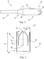
- FIG. 3 shows one exemplary embodiment of an applicator 30.
- the applicator 30 comprises an insertion member or barrel 32 and a plunger 40.
- Applicator barrel 32 has an insertion tip 34 proximal a first end 33 and an opposing withdrawal end 35.
- Applicator barrel region 36 is adapted to contain a feminine care device such as, e.g., a tampon or intravaginal incontinence device (e.g., a pessary).
- Applicator withdrawal end 35 contains a grip region 37 that can, in certain embodiments, be an indentation region.
- the grip region 37 can be demarcated from the barrel region 36, such as, e.g., by one or more shoulder regions 38.
- Grip region 37 can comprise three-dimensional surface elements that can protrude outward from the grip region.
- the present invention is primarily focused on the insertion tip of the applicator, and therefore it is not limited to any particular design features outside of the insertion tip region.
- Exemplary applicator 30 is a "full-length" applicator. But other types of applicators, including compact applicators, are contemplated by the present invention.
- Compact applicators generally employ features that permit the plunger part of the applicator to be positioned in a manner that typically shortens the packaged applicator before use. After opening the package, a consumer can then reposition the plunger so that it can be used to expel a feminine care device from the applicator barrel.
- FIG. 4 shows a partial cross-section of an applicator barrel embodiment of the present invention.
- Applicator barrel 50 includes an insertion tip 52 proximal a first end 53.
- a plurality of petals 54 is disposed about insertion tip 52.
- a slot 55 exists between adjacent petals.
- Each of petals 54 has a petal base 56 and a petal length PL extending from petal base 56 to the petal distal end 57.
- Insertion tip 52 has a tip length TL defined from a point 5 mm below petal bases 56 and extending to petal distal ends 57.
- Insertion tip 52 has a tapering wall thickness along tip length TL defined by angle ⁇ .
- Some commercially-available applicators include a draft angle to aid in removing the applicator from a manufacturing mold, but these angles are generally small; for example, around 0.2 degrees.
- Embodiments of the present invention include a wall thickness angle ⁇ in insertion tip 52 that is at least twice such a draft angle.
- insertion tip 52 along tip length TL can have a wall thickness angle ⁇ of greater than or equal to 0.4 degrees, 0.5 degrees, 0.6 degrees, 0.7 degrees, 0.8 degrees, 1 degree, 2 degrees or more.
- Other wall thickness angles are contemplated by the present invention, even though they are not explicitly mentioned.
- the insertion tip comprises than one angle. That is, the insertion tip has a non-uniform taper along the tip length.
- applicator barrel 60 includes an insertion tip 62 that comprises a first angle ⁇ and a second, different angle ⁇ along different sections of tip length TL.
- the two angles can differ in dimension from one another by 50% or more.
- the first angle ⁇ is less than or equal to 0.3 degrees and second angle ⁇ is greater than or equal to 0.4 degrees.
- the wall thickness of the insertion tip varies by at least 15%, 20%, or 25% over a 3 mm, 4 mm, or 5 mm section along the tip length to create a petal doming inflection point. This creates a step change in wall thickness.
- a thickness step change can be imparted via a single wall thickness angle with surrounding sections being devoid of a wall thickness taper, or via two or more angles as described above in connection with Figure 5 .
- Petal inflection points of the present invention can exist proximal the petal bases.
- petal inflection points can exist above the petal bases; for example, at least 1 mm, at least 2 mm, or at least 3 mm above the petal bases.
- Petal wall thickness can also vary circumferentially along the width of the petals.
- applicator barrel 70 includes an insertion tip 72 with a plurality of petals 74.
- petals 74 includes opposing first and second edges 75/76, a petal width PW extending circumferentially from first edge 75 to second edge 76, and inner surface 77, and petal thickness 78.
- Ribs 80 extend along a portion of the first and second edges 75/76 of petals 74. The petal inflection point will occur at the distal ends of ribs 80.
- ribs 80 can extend longitudinally beyond the petal bases.
- the number, location, and geometrical features of the ribs can vary from that shown in Figure 6 .
- Applicator barrel 90 includes an insertion tip 91 having a plurality of petals 92 with slots 93 between adjacent petals. As shown in Figure 7 , a portion of slots 93 include material 94.
- the bridging material 94 will preferably only extend along a portion of the petal length PL. Bridging material 94 will generally only extend a portion of the petal thickness as can be seen in Figure 7 .
- the bridging material can be the same or different from the material used to manufacture the surrounding applicator features.
- the applicator barrel and plunger can be constructed from any suitable material.
- suitable materials include, for example, paper, paperboard, cardboard, cellulose, such as, e.g., molded cellulose, or any combinations thereof, polyethylene, polypropylene, polybutylene, polystyrene, polyvinylchloride, polyacrylate, polymethacrylate, polyacrylonitrile, polyacrylamide, polyamide, nylon, polyimide, polyester, polycarbonate, polylactic acid, poly hydroxyalkanoate, ethylene vinyl acetate, polyurethane, silicone, derivatives thereof, copolymers thereof, mixtures thereof, or any suitable smooth plastic material. Examples of suitable materials are disclosed in, e.g., U.S. Pat. Nos.
- additives can be included in the material to alter or enhance certain material properties. Suitable additives include, for example, mold release agents, slip agents, surface energy modifiers, pearlescent agents, and/or any other suitable additives.
- the applicator barrel can be coated with a substance to give it a high slip characteristic, such as, e.g., with wax, polyethylene, a combination of wax and polyethylene, cellophane, clay, mica, and other lubricants that can facilitate comfortable insertion.
- the applicator components can include a textured surface.
- Texture can be provided in any suitable manner, such as, e.g., by designing texture into or adding texture to the applicator components.
- a rubbery material such as thermoplastic elastomer can be included in the gripping region of the applicator barrel.
- Applicator components can be made by a number of different techniques, including, for example, by injection molding, blow molding, spirally winding layers of material, and convolutedly winding one or more layers.
- Applicators of the present invention are preferably made from a thermoplastic polymer material and are injection molded.
- the applicator barrels are preferably molded with the petals in an open position and then post-domed using additional equipment and processes (e.g., urging the applicator insertion tip into a heated doming die). It should be appreciated however that the insertion tip and petal features described herein can be applied to applicators that are formed with the petals in a closed configuration.
Landscapes
- Health & Medical Sciences (AREA)
- Epidemiology (AREA)
- Engineering & Computer Science (AREA)
- Biomedical Technology (AREA)
- Heart & Thoracic Surgery (AREA)
- Vascular Medicine (AREA)
- Life Sciences & Earth Sciences (AREA)
- Animal Behavior & Ethology (AREA)
- General Health & Medical Sciences (AREA)
- Public Health (AREA)
- Veterinary Medicine (AREA)
- Absorbent Articles And Supports Therefor (AREA)
- Orthopedics, Nursing, And Contraception (AREA)
Description
- The present invention relates to applicators for inserting feminine care devices into the body.
- Applicators for inserting feminine care devices such as tampons and incontinence devices into the body are well known. Most commercially-available applicators have a plurality of flexible petals on their insertion end that are converged to substantially close the applicator before use. A substantially closed applicator is desired to secure the feminine care device, to maintain the condition of the device such as its cleanliness, and to improve applicator insertion comfort. Once the applicator is inserted into the body, a user can then cause the contained feminine care device to be expelled from the applicator, which includes flexing the petals outwardly to "open" the applicator insertion end to permit the feminine care device to pass through and be expelled from the applicator.
- Some applicators are made with the flexible petals in their closed position. Many applicators though are initially made with the flexible petals in an open position to permit a feminine care device to be loaded into the applicator from the insertion end rather than from an opposing gripping end. An example of this type of applicator is shown in
Figure 1 , wherein the insertion end ofexemplary applicator 10 is illustrated with its plurality ofpetals 12 in their as-molded or open state. After a feminine care device is loaded into the applicator, the petals are repositioned inwardly through pressure and heat for example. This process can be called post-doming the applicator. - During the post-doming process the insertion petals tend to flex/bend at their respective bases. But this can limit design options for both the petals themselves and the resulting insertion end as defined by the collection of repositioned petals. For example, it may be desirable to include relatively long petal lengths to reduce the amount of force required to open the petals and expel the feminine care device. But an aggressive-appearing insertion end can result as petal lengths increase and flex at their bases during post-doming; that is, the applicator insertion end can become too tapered and "pointy" looking.
Figure 2 illustrates this problem. As shown inFigure 2 , a simplistic formingdie 20 can be employed to create a hemispherical-shaped applicator insertion tip, but relativelylong petals 22 with a tendency to bend at theirbases 24 bend prematurely in the die to result in an aggressively-tapered applicator tip. While the expulsion force associated with the relatively long petals may be a positive, the applicator tip may give the appearance of uncomfortable insertion into the body. The scenario shown inFigure 2 can also result in petals overlapping at their distal ends, with doming heat and pressure potentially causing the distal ends to become stuck to one another to cause expulsion of the feminine care device undesirably difficult or impossible to expel from the applicator. Embodiments of the present invention can address this and other problems through novel thickness profiles of the applicator insertion tip, the petals and/or surrounding applicator structure.US3895634 andSU2004/249352A1 - According to the present invention, the object is achieved by an applicator having the characteristics of claim 1. Further, preferred embodiments are covered by the dependent claims. These and other embodiments are described in greater detail below.
- The following detailed description of specific embodiments of the present invention can be best understood when read in conjunction with the drawings enclosed herewith.
-
Figure 1 is a partial perspective view of an applicator barrel. -
Figure 2 is a schematic of a post-doming die and applicator insertion tip. -
Figure 3 is a plan view of an applicator comprising a barrel and a plunger. -
Figure 4 is a partial cross-sectional view of an applicator insertion tip according to the present invention. -
Figure 5 is a partial cross-sectional view of an applicator insertion tip according to the present invention. -
Figure 6 is a partial cross-sectional view of an applicator insertion tip according to the present invention. -
Figure 7 is a partial plan view of an applicator insertion tip according to the present invention. - The embodiments set forth in the drawings are illustrative in nature and not intended to be limiting of the invention defined by the claims. Moreover, individual features of the drawings and invention will be more fully apparent and understood in view of the detailed description.
- The following text sets forth a broad description of numerous different embodiments of the present invention. The description is to be construed as exemplary only and does not describe every possible embodiment since describing every possible embodiment would be impractical, if not impossible, and it will be understood that any feature, characteristic, component, composition, ingredient, product, step or methodology described herein can be deleted, combined with or substituted for, in whole or part, any other feature, characteristic, component, composition, ingredient, product, step or methodology described herein. Numerous alternative embodiments could be implemented, using either current technology or technology developed after the filing date of this patent, which would still fall within the scope of the claims.
- The present invention generally relates to applicators having improved characteristics. Referring now to the figures,
Figure 3 shows one exemplary embodiment of anapplicator 30. Theapplicator 30 comprises an insertion member orbarrel 32 and aplunger 40.Applicator barrel 32 has aninsertion tip 34 proximal afirst end 33 and an opposingwithdrawal end 35.Applicator barrel region 36 is adapted to contain a feminine care device such as, e.g., a tampon or intravaginal incontinence device (e.g., a pessary).Applicator withdrawal end 35 contains agrip region 37 that can, in certain embodiments, be an indentation region. In addition, in certain embodiments, such as, for example, when thegrip region 37 is an indentation region, thegrip region 37 can be demarcated from thebarrel region 36, such as, e.g., by one ormore shoulder regions 38.Grip region 37 can comprise three-dimensional surface elements that can protrude outward from the grip region. The present invention is primarily focused on the insertion tip of the applicator, and therefore it is not limited to any particular design features outside of the insertion tip region.Exemplary applicator 30 is a "full-length" applicator. But other types of applicators, including compact applicators, are contemplated by the present invention. Compact applicators generally employ features that permit the plunger part of the applicator to be positioned in a manner that typically shortens the packaged applicator before use. After opening the package, a consumer can then reposition the plunger so that it can be used to expel a feminine care device from the applicator barrel. -
Figure 4 shows a partial cross-section of an applicator barrel embodiment of the present invention.Applicator barrel 50 includes aninsertion tip 52 proximal afirst end 53. A plurality ofpetals 54 is disposed aboutinsertion tip 52. Aslot 55 exists between adjacent petals. Each ofpetals 54 has apetal base 56 and a petal length PL extending frompetal base 56 to the petaldistal end 57.Insertion tip 52 has a tip length TL defined from a point 5 mm below petal bases 56 and extending to petal distal ends 57. -
Insertion tip 52 has a tapering wall thickness along tip length TL defined by angle α. Some commercially-available applicators include a draft angle to aid in removing the applicator from a manufacturing mold, but these angles are generally small; for example, around 0.2 degrees. Embodiments of the present invention include a wall thickness angle α ininsertion tip 52 that is at least twice such a draft angle. For example,insertion tip 52 along tip length TL can have a wall thickness angle α of greater than or equal to 0.4 degrees, 0.5 degrees, 0.6 degrees, 0.7 degrees, 0.8 degrees, 1 degree, 2 degrees or more. Other wall thickness angles are contemplated by the present invention, even though they are not explicitly mentioned. - The insertion tip comprises than one angle. That is, the insertion tip has a non-uniform taper along the tip length. For example and with reference to
Figure 5 ,applicator barrel 60 includes aninsertion tip 62 that comprises a first angle β and a second, different angle λ along different sections of tip length TL. The two angles can differ in dimension from one another by 50% or more. The first angle β is less than or equal to 0.3 degrees and second angle λ is greater than or equal to 0.4 degrees. - As noted in the background section, known applicator petals generally bend at the petal bases. Unique design approaches of the present invention permit the creation of one or more inflection or bending points at locations other than the petal bases. The design approaches provided by the present invention reduce and/or increase flexural resistance in targeted regions of the insertion tip. In one embodiment, the wall thickness of the insertion tip varies by at least 15%, 20%, or 25% over a 3 mm, 4 mm, or 5 mm section along the tip length to create a petal doming inflection point. This creates a step change in wall thickness. A thickness step change can be imparted via a single wall thickness angle with surrounding sections being devoid of a wall thickness taper, or via two or more angles as described above in connection with
Figure 5 . Petal inflection points of the present invention can exist proximal the petal bases. In other embodiments, petal inflection points can exist above the petal bases; for example, at least 1 mm, at least 2 mm, or at least 3 mm above the petal bases. - Petal wall thickness can also vary circumferentially along the width of the petals. One exemplary technique includes employing vertical ribs at one or more locations across the width of the petals. Referring now to
Figure 6 ,applicator barrel 70 includes aninsertion tip 72 with a plurality ofpetals 74. Each ofpetals 74 includes opposing first andsecond edges 75/76, a petal width PW extending circumferentially fromfirst edge 75 tosecond edge 76, andinner surface 77, andpetal thickness 78.Ribs 80 extend along a portion of the first andsecond edges 75/76 ofpetals 74. The petal inflection point will occur at the distal ends ofribs 80. As can be seen inFigure 6 ,ribs 80 can extend longitudinally beyond the petal bases. One of ordinary skill in the art should appreciate that the number, location, and geometrical features of the ribs can vary from that shown inFigure 6 . - Another embodiment of the present invention, with reference to
Figure 7 , includes employing material into a portion of the slots that exist between adjacent petals.Applicator barrel 90 includes aninsertion tip 91 having a plurality ofpetals 92 withslots 93 between adjacent petals. As shown inFigure 7 , a portion ofslots 93 includematerial 94. The bridgingmaterial 94 will preferably only extend along a portion of the petal length PL. Bridgingmaterial 94 will generally only extend a portion of the petal thickness as can be seen inFigure 7 . The bridging material can be the same or different from the material used to manufacture the surrounding applicator features. - The applicator barrel and plunger can be constructed from any suitable material. Suitable materials include, for example, paper, paperboard, cardboard, cellulose, such as, e.g., molded cellulose, or any combinations thereof, polyethylene, polypropylene, polybutylene, polystyrene, polyvinylchloride, polyacrylate, polymethacrylate, polyacrylonitrile, polyacrylamide, polyamide, nylon, polyimide, polyester, polycarbonate, polylactic acid, poly hydroxyalkanoate, ethylene vinyl acetate, polyurethane, silicone, derivatives thereof, copolymers thereof, mixtures thereof, or any suitable smooth plastic material. Examples of suitable materials are disclosed in, e.g.,
U.S. Pat. Nos. 5,346,468 and5,558,631 . In certain embodiments, additives can be included in the material to alter or enhance certain material properties. Suitable additives include, for example, mold release agents, slip agents, surface energy modifiers, pearlescent agents, and/or any other suitable additives. In certain embodiments, the applicator barrel can be coated with a substance to give it a high slip characteristic, such as, e.g., with wax, polyethylene, a combination of wax and polyethylene, cellophane, clay, mica, and other lubricants that can facilitate comfortable insertion. Alternatively, or in addition, the applicator components can include a textured surface. Texture can be provided in any suitable manner, such as, e.g., by designing texture into or adding texture to the applicator components. For example, a rubbery material such as thermoplastic elastomer can be included in the gripping region of the applicator barrel. - Applicator components can be made by a number of different techniques, including, for example, by injection molding, blow molding, spirally winding layers of material, and convolutedly winding one or more layers. Applicators of the present invention are preferably made from a thermoplastic polymer material and are injection molded. The applicator barrels are preferably molded with the petals in an open position and then post-domed using additional equipment and processes (e.g., urging the applicator insertion tip into a heated doming die). It should be appreciated however that the insertion tip and petal features described herein can be applied to applicators that are formed with the petals in a closed configuration.
Claims (4)
- An applicator for inserting feminine care devices into the body, the applicator comprising:a. a barrel (60) comprising an insertion tip (62) proximal a first end;b. a plurality of spaced apart petals disposed about the insertion tip, each of the petals having a petal base defined by the lowest point of a slot between the spaced apart petals and a petal length extending from the petal base to a petal distal end;c. wherein the insertion tip has a tip length defined from a point 5 mm below the petal bases and extending to the petal distal ends;d. wherein the insertion tip along the tip length has a non-uniform taper comprising a first wall thickness angle (β) of less than or equal to 0.3 degrees and a second wall thickness angle (λ) of greater than or equal to 0.4 degrees.
- The applicator of the preceding claim, wherein the insertion tip along the tip length comprises a wall thickness angle of greater than or equal to 0.5 degrees.
- The applicator of any one of the preceding claims, wherein the insertion tip along the tip length comprises a wall thickness angle of greater than or equal to 0.6 degrees.
- The applicator of any of the preceding claims, wherein the insertion tip along the tip length comprises a wall thickness angle of greater than or equal to 0.7 degrees.
Applications Claiming Priority (2)
| Application Number | Priority Date | Filing Date | Title |
|---|---|---|---|
| US201261731529P | 2012-11-30 | 2012-11-30 | |
| PCT/US2013/071424 WO2014085234A1 (en) | 2012-11-30 | 2013-11-22 | Applicator for feminine care device |
Publications (2)
| Publication Number | Publication Date |
|---|---|
| EP2925264A1 EP2925264A1 (en) | 2015-10-07 |
| EP2925264B1 true EP2925264B1 (en) | 2022-06-01 |
Family
ID=49709863
Family Applications (1)
| Application Number | Title | Priority Date | Filing Date |
|---|---|---|---|
| EP13799473.7A Active EP2925264B1 (en) | 2012-11-30 | 2013-11-22 | Applicator for feminine care device |
Country Status (5)
| Country | Link |
|---|---|
| US (1) | US9510978B2 (en) |
| EP (1) | EP2925264B1 (en) |
| JP (2) | JP2016500023A (en) |
| IL (1) | IL238916A0 (en) |
| WO (1) | WO2014085234A1 (en) |
Families Citing this family (5)
| Publication number | Priority date | Publication date | Assignee | Title |
|---|---|---|---|---|
| US9510978B2 (en) * | 2012-11-30 | 2016-12-06 | The Procter & Gamble Company | Applicator for feminine care device |
| US10201411B2 (en) * | 2015-06-29 | 2019-02-12 | The Procter & Gamble Company | Pessary with applicator |
| USD772409S1 (en) | 2015-11-09 | 2016-11-22 | Edgewell Personal Care Brands, Llc | Applicator with telescoping plunger |
| USD787673S1 (en) | 2015-11-09 | 2017-05-23 | Edgewell Personal Care Brands, Llc | Telescoping plunger |
| US11304857B2 (en) | 2016-07-22 | 2022-04-19 | Edgewell Personal Care Brands, Llc | Tampon applicator with improved insertion tip |
Family Cites Families (15)
| Publication number | Priority date | Publication date | Assignee | Title |
|---|---|---|---|---|
| US3895634A (en) * | 1973-10-18 | 1975-07-22 | Rapid American Corp | Tampon inserter |
| AU673812B2 (en) | 1992-01-13 | 1996-11-28 | Tambrands, Inc. | Tampon applicator |
| CA2095393C (en) * | 1992-05-20 | 1997-12-30 | Jamshid Rejai | Tampon applicator and method for forming same |
| US5792096A (en) | 1994-08-22 | 1998-08-11 | Kiberly-Clark Worldwide, Inc. | Tampon applicator having an improved pleated tip |
| JP3797835B2 (en) | 1999-11-19 | 2006-07-19 | ユニ・チャーム株式会社 | Tampon applicator |
| US7104968B2 (en) | 2002-06-14 | 2006-09-12 | Mcneil-Ppc, Inc. | Applicator device for suppositories and the like |
| US7217252B2 (en) | 2002-06-14 | 2007-05-15 | Mcneil-Ppc, Inc. | Applicator device for medicated materials |
| US8444590B2 (en) | 2002-06-21 | 2013-05-21 | Playtex Products, Inc. | Tapered tampon applicator with petals and taper ratio |
| US8372027B2 (en) * | 2003-04-04 | 2013-02-12 | Playtex Products, Inc. | Tampon applicator assembly |
| EP1622558B1 (en) | 2003-05-02 | 2012-11-14 | Playtex Products, Inc. | Tampon assembly having shaped pledget |
| WO2009079607A1 (en) * | 2007-12-18 | 2009-06-25 | Osel, Inc. | Applicator for applying powder formulations and uses thereof |
| US9339419B2 (en) | 2008-07-15 | 2016-05-17 | Kimberly-Clark Worldwide, Inc. | Tampon applicator |
| US20110201992A1 (en) * | 2008-10-24 | 2011-08-18 | Ontex Hygieneartikel Deutschland Gmbh | Tampon applicator |
| US8734414B2 (en) * | 2009-12-17 | 2014-05-27 | Kimberly-Clark Worldwide, Inc. | Pull-activated tampon applicator |
| US9510978B2 (en) * | 2012-11-30 | 2016-12-06 | The Procter & Gamble Company | Applicator for feminine care device |
-
2013
- 2013-11-21 US US14/086,126 patent/US9510978B2/en active Active
- 2013-11-22 WO PCT/US2013/071424 patent/WO2014085234A1/en not_active Ceased
- 2013-11-22 JP JP2015545118A patent/JP2016500023A/en active Pending
- 2013-11-22 EP EP13799473.7A patent/EP2925264B1/en active Active
-
2015
- 2015-05-20 IL IL238916A patent/IL238916A0/en unknown
-
2017
- 2017-01-24 JP JP2017010608A patent/JP2017121489A/en active Pending
Also Published As
| Publication number | Publication date |
|---|---|
| US20140155808A1 (en) | 2014-06-05 |
| WO2014085234A1 (en) | 2014-06-05 |
| US9510978B2 (en) | 2016-12-06 |
| JP2016500023A (en) | 2016-01-07 |
| EP2925264A1 (en) | 2015-10-07 |
| JP2017121489A (en) | 2017-07-13 |
| IL238916A0 (en) | 2015-07-30 |
Similar Documents
| Publication | Publication Date | Title |
|---|---|---|
| US8458882B2 (en) | Method for assembling a tampon applicator | |
| US6685788B2 (en) | Method of making applicators having improved finger grip features | |
| US9510978B2 (en) | Applicator for feminine care device | |
| US20020143287A1 (en) | Applicator having improved gripper end | |
| CN102791236B (en) | Pull-activated tampon applicator | |
| US6423025B1 (en) | Catamenial applicator having a fingergrip | |
| US8308675B2 (en) | Applicator device | |
| US20040199102A1 (en) | Tampon applicator assembly | |
| JP2001500046A (en) | Flexible applicator for insertion of product into the body cavity of a mammal | |
| MXPA03000128A (en) | Tampon applicator having improved finger grip. | |
| US6322531B1 (en) | Insertable applicator having a pivotal finger grip tab | |
| EP2001426A1 (en) | Applicator device | |
| JP6321175B2 (en) | Profile heat sealing method | |
| CA2521246C (en) | Improved tampon applicator assembly | |
| AU2007203266A1 (en) | Applicator having improved gripper end | |
| AU2002248703A1 (en) | Applicator having improved gripper end |
Legal Events
| Date | Code | Title | Description |
|---|---|---|---|
| PUAI | Public reference made under article 153(3) epc to a published international application that has entered the european phase |
Free format text: ORIGINAL CODE: 0009012 |
|
| 17P | Request for examination filed |
Effective date: 20150507 |
|
| AK | Designated contracting states |
Kind code of ref document: A1 Designated state(s): AL AT BE BG CH CY CZ DE DK EE ES FI FR GB GR HR HU IE IS IT LI LT LU LV MC MK MT NL NO PL PT RO RS SE SI SK SM TR |
|
| AX | Request for extension of the european patent |
Extension state: BA ME |
|
| DAX | Request for extension of the european patent (deleted) | ||
| STAA | Information on the status of an ep patent application or granted ep patent |
Free format text: STATUS: EXAMINATION IS IN PROGRESS |
|
| 17Q | First examination report despatched |
Effective date: 20170914 |
|
| GRAP | Despatch of communication of intention to grant a patent |
Free format text: ORIGINAL CODE: EPIDOSNIGR1 |
|
| STAA | Information on the status of an ep patent application or granted ep patent |
Free format text: STATUS: GRANT OF PATENT IS INTENDED |
|
| INTG | Intention to grant announced |
Effective date: 20211222 |
|
| GRAS | Grant fee paid |
Free format text: ORIGINAL CODE: EPIDOSNIGR3 |
|
| GRAA | (expected) grant |
Free format text: ORIGINAL CODE: 0009210 |
|
| STAA | Information on the status of an ep patent application or granted ep patent |
Free format text: STATUS: THE PATENT HAS BEEN GRANTED |
|
| AK | Designated contracting states |
Kind code of ref document: B1 Designated state(s): AL AT BE BG CH CY CZ DE DK EE ES FI FR GB GR HR HU IE IS IT LI LT LU LV MC MK MT NL NO PL PT RO RS SE SI SK SM TR |
|
| REG | Reference to a national code |
Ref country code: GB Ref legal event code: FG4D |
|
| REG | Reference to a national code |
Ref country code: AT Ref legal event code: REF Ref document number: 1494900 Country of ref document: AT Kind code of ref document: T Effective date: 20220615 Ref country code: CH Ref legal event code: EP |
|
| REG | Reference to a national code |
Ref country code: IE Ref legal event code: FG4D |
|
| REG | Reference to a national code |
Ref country code: DE Ref legal event code: R096 Ref document number: 602013081766 Country of ref document: DE |
|
| REG | Reference to a national code |
Ref country code: LT Ref legal event code: MG9D |
|
| REG | Reference to a national code |
Ref country code: NL Ref legal event code: MP Effective date: 20220601 |
|
| REG | Reference to a national code |
Ref country code: FR Ref legal event code: PLFP Year of fee payment: 10 |
|
| PG25 | Lapsed in a contracting state [announced via postgrant information from national office to epo] |
Ref country code: SE Free format text: LAPSE BECAUSE OF FAILURE TO SUBMIT A TRANSLATION OF THE DESCRIPTION OR TO PAY THE FEE WITHIN THE PRESCRIBED TIME-LIMIT Effective date: 20220601 Ref country code: NO Free format text: LAPSE BECAUSE OF FAILURE TO SUBMIT A TRANSLATION OF THE DESCRIPTION OR TO PAY THE FEE WITHIN THE PRESCRIBED TIME-LIMIT Effective date: 20220901 Ref country code: LT Free format text: LAPSE BECAUSE OF FAILURE TO SUBMIT A TRANSLATION OF THE DESCRIPTION OR TO PAY THE FEE WITHIN THE PRESCRIBED TIME-LIMIT Effective date: 20220601 Ref country code: HR Free format text: LAPSE BECAUSE OF FAILURE TO SUBMIT A TRANSLATION OF THE DESCRIPTION OR TO PAY THE FEE WITHIN THE PRESCRIBED TIME-LIMIT Effective date: 20220601 Ref country code: GR Free format text: LAPSE BECAUSE OF FAILURE TO SUBMIT A TRANSLATION OF THE DESCRIPTION OR TO PAY THE FEE WITHIN THE PRESCRIBED TIME-LIMIT Effective date: 20220902 Ref country code: FI Free format text: LAPSE BECAUSE OF FAILURE TO SUBMIT A TRANSLATION OF THE DESCRIPTION OR TO PAY THE FEE WITHIN THE PRESCRIBED TIME-LIMIT Effective date: 20220601 Ref country code: ES Free format text: LAPSE BECAUSE OF FAILURE TO SUBMIT A TRANSLATION OF THE DESCRIPTION OR TO PAY THE FEE WITHIN THE PRESCRIBED TIME-LIMIT Effective date: 20220601 Ref country code: BG Free format text: LAPSE BECAUSE OF FAILURE TO SUBMIT A TRANSLATION OF THE DESCRIPTION OR TO PAY THE FEE WITHIN THE PRESCRIBED TIME-LIMIT Effective date: 20220901 |
|
| REG | Reference to a national code |
Ref country code: AT Ref legal event code: MK05 Ref document number: 1494900 Country of ref document: AT Kind code of ref document: T Effective date: 20220601 |
|
| PG25 | Lapsed in a contracting state [announced via postgrant information from national office to epo] |
Ref country code: RS Free format text: LAPSE BECAUSE OF FAILURE TO SUBMIT A TRANSLATION OF THE DESCRIPTION OR TO PAY THE FEE WITHIN THE PRESCRIBED TIME-LIMIT Effective date: 20220601 Ref country code: PL Free format text: LAPSE BECAUSE OF FAILURE TO SUBMIT A TRANSLATION OF THE DESCRIPTION OR TO PAY THE FEE WITHIN THE PRESCRIBED TIME-LIMIT Effective date: 20220601 Ref country code: LV Free format text: LAPSE BECAUSE OF FAILURE TO SUBMIT A TRANSLATION OF THE DESCRIPTION OR TO PAY THE FEE WITHIN THE PRESCRIBED TIME-LIMIT Effective date: 20220601 |
|
| PG25 | Lapsed in a contracting state [announced via postgrant information from national office to epo] |
Ref country code: NL Free format text: LAPSE BECAUSE OF FAILURE TO SUBMIT A TRANSLATION OF THE DESCRIPTION OR TO PAY THE FEE WITHIN THE PRESCRIBED TIME-LIMIT Effective date: 20220601 |
|
| PG25 | Lapsed in a contracting state [announced via postgrant information from national office to epo] |
Ref country code: SM Free format text: LAPSE BECAUSE OF FAILURE TO SUBMIT A TRANSLATION OF THE DESCRIPTION OR TO PAY THE FEE WITHIN THE PRESCRIBED TIME-LIMIT Effective date: 20220601 Ref country code: SK Free format text: LAPSE BECAUSE OF FAILURE TO SUBMIT A TRANSLATION OF THE DESCRIPTION OR TO PAY THE FEE WITHIN THE PRESCRIBED TIME-LIMIT Effective date: 20220601 Ref country code: RO Free format text: LAPSE BECAUSE OF FAILURE TO SUBMIT A TRANSLATION OF THE DESCRIPTION OR TO PAY THE FEE WITHIN THE PRESCRIBED TIME-LIMIT Effective date: 20220601 Ref country code: PT Free format text: LAPSE BECAUSE OF FAILURE TO SUBMIT A TRANSLATION OF THE DESCRIPTION OR TO PAY THE FEE WITHIN THE PRESCRIBED TIME-LIMIT Effective date: 20221003 Ref country code: EE Free format text: LAPSE BECAUSE OF FAILURE TO SUBMIT A TRANSLATION OF THE DESCRIPTION OR TO PAY THE FEE WITHIN THE PRESCRIBED TIME-LIMIT Effective date: 20220601 Ref country code: CZ Free format text: LAPSE BECAUSE OF FAILURE TO SUBMIT A TRANSLATION OF THE DESCRIPTION OR TO PAY THE FEE WITHIN THE PRESCRIBED TIME-LIMIT Effective date: 20220601 Ref country code: AT Free format text: LAPSE BECAUSE OF FAILURE TO SUBMIT A TRANSLATION OF THE DESCRIPTION OR TO PAY THE FEE WITHIN THE PRESCRIBED TIME-LIMIT Effective date: 20220601 |
|
| PG25 | Lapsed in a contracting state [announced via postgrant information from national office to epo] |
Ref country code: IS Free format text: LAPSE BECAUSE OF FAILURE TO SUBMIT A TRANSLATION OF THE DESCRIPTION OR TO PAY THE FEE WITHIN THE PRESCRIBED TIME-LIMIT Effective date: 20221001 |
|
| REG | Reference to a national code |
Ref country code: DE Ref legal event code: R097 Ref document number: 602013081766 Country of ref document: DE |
|
| PG25 | Lapsed in a contracting state [announced via postgrant information from national office to epo] |
Ref country code: AL Free format text: LAPSE BECAUSE OF FAILURE TO SUBMIT A TRANSLATION OF THE DESCRIPTION OR TO PAY THE FEE WITHIN THE PRESCRIBED TIME-LIMIT Effective date: 20220601 |
|
| PLBE | No opposition filed within time limit |
Free format text: ORIGINAL CODE: 0009261 |
|
| STAA | Information on the status of an ep patent application or granted ep patent |
Free format text: STATUS: NO OPPOSITION FILED WITHIN TIME LIMIT |
|
| PG25 | Lapsed in a contracting state [announced via postgrant information from national office to epo] |
Ref country code: DK Free format text: LAPSE BECAUSE OF FAILURE TO SUBMIT A TRANSLATION OF THE DESCRIPTION OR TO PAY THE FEE WITHIN THE PRESCRIBED TIME-LIMIT Effective date: 20220601 |
|
| 26N | No opposition filed |
Effective date: 20230302 |
|
| PG25 | Lapsed in a contracting state [announced via postgrant information from national office to epo] |
Ref country code: SI Free format text: LAPSE BECAUSE OF FAILURE TO SUBMIT A TRANSLATION OF THE DESCRIPTION OR TO PAY THE FEE WITHIN THE PRESCRIBED TIME-LIMIT Effective date: 20220601 |
|
| P01 | Opt-out of the competence of the unified patent court (upc) registered |
Effective date: 20230429 |
|
| PG25 | Lapsed in a contracting state [announced via postgrant information from national office to epo] |
Ref country code: MC Free format text: LAPSE BECAUSE OF FAILURE TO SUBMIT A TRANSLATION OF THE DESCRIPTION OR TO PAY THE FEE WITHIN THE PRESCRIBED TIME-LIMIT Effective date: 20220601 |
|
| REG | Reference to a national code |
Ref country code: CH Ref legal event code: PL |
|
| REG | Reference to a national code |
Ref country code: BE Ref legal event code: MM Effective date: 20221130 |
|
| PG25 | Lapsed in a contracting state [announced via postgrant information from national office to epo] |
Ref country code: LI Free format text: LAPSE BECAUSE OF NON-PAYMENT OF DUE FEES Effective date: 20221130 Ref country code: CH Free format text: LAPSE BECAUSE OF NON-PAYMENT OF DUE FEES Effective date: 20221130 |
|
| PG25 | Lapsed in a contracting state [announced via postgrant information from national office to epo] |
Ref country code: LU Free format text: LAPSE BECAUSE OF NON-PAYMENT OF DUE FEES Effective date: 20221122 |
|
| PG25 | Lapsed in a contracting state [announced via postgrant information from national office to epo] |
Ref country code: IE Free format text: LAPSE BECAUSE OF NON-PAYMENT OF DUE FEES Effective date: 20221122 |
|
| PG25 | Lapsed in a contracting state [announced via postgrant information from national office to epo] |
Ref country code: BE Free format text: LAPSE BECAUSE OF NON-PAYMENT OF DUE FEES Effective date: 20221130 |
|
| PG25 | Lapsed in a contracting state [announced via postgrant information from national office to epo] |
Ref country code: IT Free format text: LAPSE BECAUSE OF FAILURE TO SUBMIT A TRANSLATION OF THE DESCRIPTION OR TO PAY THE FEE WITHIN THE PRESCRIBED TIME-LIMIT Effective date: 20220601 |
|
| PG25 | Lapsed in a contracting state [announced via postgrant information from national office to epo] |
Ref country code: HU Free format text: LAPSE BECAUSE OF FAILURE TO SUBMIT A TRANSLATION OF THE DESCRIPTION OR TO PAY THE FEE WITHIN THE PRESCRIBED TIME-LIMIT; INVALID AB INITIO Effective date: 20131122 |
|
| PG25 | Lapsed in a contracting state [announced via postgrant information from national office to epo] |
Ref country code: CY Free format text: LAPSE BECAUSE OF FAILURE TO SUBMIT A TRANSLATION OF THE DESCRIPTION OR TO PAY THE FEE WITHIN THE PRESCRIBED TIME-LIMIT Effective date: 20220601 |
|
| PG25 | Lapsed in a contracting state [announced via postgrant information from national office to epo] |
Ref country code: MK Free format text: LAPSE BECAUSE OF FAILURE TO SUBMIT A TRANSLATION OF THE DESCRIPTION OR TO PAY THE FEE WITHIN THE PRESCRIBED TIME-LIMIT Effective date: 20220601 |
|
| PG25 | Lapsed in a contracting state [announced via postgrant information from national office to epo] |
Ref country code: TR Free format text: LAPSE BECAUSE OF FAILURE TO SUBMIT A TRANSLATION OF THE DESCRIPTION OR TO PAY THE FEE WITHIN THE PRESCRIBED TIME-LIMIT Effective date: 20220601 |
|
| PG25 | Lapsed in a contracting state [announced via postgrant information from national office to epo] |
Ref country code: MT Free format text: LAPSE BECAUSE OF FAILURE TO SUBMIT A TRANSLATION OF THE DESCRIPTION OR TO PAY THE FEE WITHIN THE PRESCRIBED TIME-LIMIT Effective date: 20220601 |
|
| PG25 | Lapsed in a contracting state [announced via postgrant information from national office to epo] |
Ref country code: BG Free format text: LAPSE BECAUSE OF FAILURE TO SUBMIT A TRANSLATION OF THE DESCRIPTION OR TO PAY THE FEE WITHIN THE PRESCRIBED TIME-LIMIT Effective date: 20220601 |
|
| PG25 | Lapsed in a contracting state [announced via postgrant information from national office to epo] |
Ref country code: BG Free format text: LAPSE BECAUSE OF FAILURE TO SUBMIT A TRANSLATION OF THE DESCRIPTION OR TO PAY THE FEE WITHIN THE PRESCRIBED TIME-LIMIT Effective date: 20220601 |
|
| PGFP | Annual fee paid to national office [announced via postgrant information from national office to epo] |
Ref country code: GB Payment date: 20250930 Year of fee payment: 13 |
|
| PGFP | Annual fee paid to national office [announced via postgrant information from national office to epo] |
Ref country code: FR Payment date: 20250930 Year of fee payment: 13 |
|
| PGFP | Annual fee paid to national office [announced via postgrant information from national office to epo] |
Ref country code: DE Payment date: 20250930 Year of fee payment: 13 |