EP2925103A1 - Cable management device - Google Patents
Cable management device Download PDFInfo
- Publication number
- EP2925103A1 EP2925103A1 EP14162032.8A EP14162032A EP2925103A1 EP 2925103 A1 EP2925103 A1 EP 2925103A1 EP 14162032 A EP14162032 A EP 14162032A EP 2925103 A1 EP2925103 A1 EP 2925103A1
- Authority
- EP
- European Patent Office
- Prior art keywords
- support arm
- guiding portion
- cable management
- connecting member
- support
- Prior art date
- Legal status (The legal status is an assumption and is not a legal conclusion. Google has not performed a legal analysis and makes no representation as to the accuracy of the status listed.)
- Granted
Links
Images




Classifications
-
- H—ELECTRICITY
- H05—ELECTRIC TECHNIQUES NOT OTHERWISE PROVIDED FOR
- H05K—PRINTED CIRCUITS; CASINGS OR CONSTRUCTIONAL DETAILS OF ELECTRIC APPARATUS; MANUFACTURE OF ASSEMBLAGES OF ELECTRICAL COMPONENTS
- H05K7/00—Constructional details common to different types of electric apparatus
- H05K7/14—Mounting supporting structure in casing or on frame or rack
- H05K7/1485—Servers; Data center rooms, e.g. 19-inch computer racks
- H05K7/1488—Cabinets therefor, e.g. chassis or racks or mechanical interfaces between blades and support structures
- H05K7/1491—Cabinets therefor, e.g. chassis or racks or mechanical interfaces between blades and support structures having cable management arrangements
Definitions
- the present invention relates to a cable management device and more particularly to a cable management device applicable to a rack server.
- a rack server is a server mounted on a rack.
- each of two corresponding lateral sides of a rack server is equipped with a slide rail assembly via which the server is mounted to a rack and which allows the server to be pulled out from the rack and pushed back into the rack in a similar way to a drawer.
- a rack server has or is connected with a large number of electronic cables. While the server is pulled out from or pushed into a rack by means of a pair of slide rail assemblies, the cables may become untidy unless a device for managing or receiving the cables is used.
- US Patent No. 8,379,410 discloses a reversible cable management arm system which essentially includes two connected cable support arms (138, 140) and a pivotable connector (150) located between the two cable support arms (138, 140). As shown in FIG. 6 and FIG. 7 of the '410 patent, one of the cable support arms (138) is connected with a second attachment member (152b), which is pivotally connected to a snap-on connector (160). The snap-on connector (160) is connected to the connector receiver (154) of a first slide member (134a). The other cable support arm (140) is connected with a first attachment member (152a), which is pivotally connected to another snap-on connector (158).
- This snap-on connector (158) is connected to the connector receiver (154) of a second slide member (134b).
- the cable support arm (138) and the second attachment member (152b) are interconnected by a tension member (172), and the cable support arm (140) and the first attachment member (152a) are interconnected by another tension member (170).
- cables (142) can remain tidy in the course where a server chassis (130) is pulled out from or pushed into a rack (132).
- the tension members (170, 172) respectively render the first attachment member (152a) and the second attachment member (152b) reversible in direction so that the folding direction of the cables (142) can be maintained.
- tension members (170, 172) which are springs, may undergo elastic fatigue or even become rusty after long-term use. In either case, the function of the cable management arm system as a whole will be compromised.
- the present invention relates to a cable management device for use with a rack server.
- a cable management device applicable to a rack server includes a first support arm, a second support arm, and a connecting member.
- the first support arm includes a front portion, a rear portion, and a first guiding portion located at the front portion of the first support arm.
- the second support arm includes a front portion, a rear portion, and a first guiding portion located at the front portion of the second support arm.
- the connecting member is movably connected between the first support arm and the second support arm.
- the connecting member includes a front guiding portion and a rear guiding portion. The first guiding portion of the first support arm can move along and relative to the front guiding portion of the connecting member, and the first guiding portion of the second support arm can move along and relative to the rear guiding portion of the connecting member.
- each of the front guiding portion and the rear guiding portion of the connecting member is a curved groove
- each of the first guiding portion of the first support arm and the first guiding portion of the second support arm is a protruding block movable only within the limited space defined by the corresponding one of the curved grooves.
- Each of the curved grooves defines a path corresponding to a 90-degree circular arc.
- a cable management device applicable to a chassis wherein the chassis has a lateral side mounted to a rack by means of a slide rail assembly.
- the cable management device includes a first cable management arm which includes a first support arm, a second support arm, a first connecting member, a third support arm, and a second connecting member.
- the first support arm includes a front portion, a rear portion, a first guiding portion located at the front portion of the first support arm, and a second guiding portion located at the rear portion of the first support arm.
- the second support arm includes a front portion, a rear portion, a first guiding portion located at the front portion of the second support arm, and a second guiding portion located at the rear portion of the second support arm.
- the first connecting member is movably connected between the front portion of the first support arm and the front portion of the second support arm.
- the first connecting member includes a front guiding portion and a rear guiding portion.
- the third support arm includes a front portion, a rear portion, a first guiding portion located at the front portion of the third support arm, and a second guiding portion located at the rear portion of the third support arm.
- the second connecting member is movably connected between the rear portion of the second support arm and the rear portion of the third support arm.
- the second connecting member includes a front guiding portion and a rear guiding portion.
- the rear portion of the first support arm is movably connected to the chassis.
- the front portion of the third support arm is movably connected to one of the slide rail assembly and the rack.
- the first guiding portion of the first support arm is moved along and relative to the front guiding portion of the first connecting member
- the first guiding portion of the second support arm is moved along and relative to the rear guiding portion of the first connecting member
- the second guiding portion of the second support arm is moved along and relative to the front guiding portion of the second connecting member
- the second guiding portion of the third support arm is moved along and relative to the rear guiding portion of the second connecting member; as a result, the first support arm, the first connecting member, the second support arm, the second connecting member, and the third support arm are driven to an extended position.
- the cable management device further includes a first support member and a second support member.
- the first support member is connected between the chassis and the rear portion of the first support arm.
- the second support member is connected either between the slide rail assembly and the front portion of the third support arm or between the rack and the front portion of the third support arm.
- the front guiding portions and the rear guiding portions of the first connecting member and the second connecting member are curved grooves; and the first guiding portion of the first support arm, the first guiding portion and the second guiding portion of the second support arm, and the second guiding portion of the third support arm are protruding blocks respectively movable only within the limited spaces respectively defined by the curved grooves.
- Each of the curved grooves defines a path corresponding to a 90-degree circular arc.
- a cable management device applicable to a chassis wherein the chassis is mounted to a rack by means of a pair of slide rail assemblies.
- the cable management device includes a first cable management arm and a second cable management arm. At least one of the first cable management arm and the second cable management arm at least includes a first support arm, a second support arm, a first connecting member, a third support arm, and a second connecting member.
- the first support arm includes a front portion, a rear portion, a first guiding portion located at the front portion of the first support arm, and a second guiding portion located at the rear portion of the first support arm.
- the second support arm includes a front portion, a rear portion, a first guiding portion located at the front portion of the second support arm, and a second guiding portion located at the rear portion of the second support arm.
- the first connecting member is movably connected between the front portion of the first support arm and the front portion of the second support arm.
- the first connecting member includes a front guiding portion and a rear guiding portion.
- the third support arm includes a front portion, a rear portion, a first guiding portion located at the front portion of the third support arm, and a second guiding portion located at the rear portion of the third support arm.
- the second connecting member is movably connected between the rear portion of the second support arm and the rear portion of the third support arm.
- the second connecting member includes a front guiding portion and a rear guiding portion.
- the rear portion of the first support arm is movably connected to the chassis.
- the front portion of the third support arm is movably connected to one of the slide rail assemblies or is movably connected to the rack.
- the first guiding portion of the first support arm is moved along and relative to the front guiding portion of the first connecting member
- the first guiding portion of the second support arm is moved along and relative to the rear guiding portion of the first connecting member
- the second guiding portion of the second support arm is moved along and relative to the front guiding portion of the second connecting member
- the second guiding portion of the third support arm is moved along and relative to the rear guiding portion of the second connecting member; as a result, the first support arm, the first connecting member, the second support arm, the second connecting member, and the third support arm are driven to an extended position.
- the cable management device further includes a first support member, a second support member, a third support member, and a fourth support member.
- the first support member is movably connected between the chassis and the first cable management arm.
- the second support member is movably connected between the first cable management arm and one of the slide rail assemblies.
- the third support member is movably connected between the chassis and the second cable management arm.
- the fourth support member is movably connected between the second cable management arm and the other one of the slide rail assemblies.
- the first support member and the third support member are respectively connected to the chassis at positions adjacent to a rear middle part of the chassis.
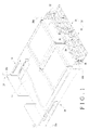
- FIG. 1 shows a rack 10, a chassis 12, a first slide rail assembly 14, a second slide rail assembly 16, and a cable management device 18.
- the rack 10 includes a first post 20a, a second post 20b, a third post 20c, and a fourth post 20d.
- the first post 20a and the second post 20b correspond in position to the third post 20c and the fourth post 20d respectively.
- the chassis 12 has one lateral side mounted between the first post 20a and the second post 20b of the rack 10 by means of the first slide rail assembly 14.
- the opposite lateral side of the chassis 12 is mounted between the third post 20c and the fourth post 20d of the rack 10 by means of the second slide rail assembly 16.
- the cable management device 18 includes at least one cable management arm and preferably includes a first cable management arm 22 and a second cable management arm 24.
- the first cable management arm 22 and the second cable management arm 24 have substantially the same structural features.
- the first cable management arm 22 is movably connected between the chassis 12 and the first slide rail assembly 14.
- the second cable management arm 24 is movably connected between the chassis 12 and the second slide rail assembly 16.
- a first support member 26 is movably connected between the chassis 12 and the first cable management arm 22, and a second support member 28 is movably connected between the first cable management arm 22 and the first slide rail assembly 14.
- a third support member 30 is movably connected between the chassis 12 and the second cable management arm 24, and a fourth support member 32 is movably connected between the second cable management arm 24 and the second slide rail assembly 16.
- the first support member 26 and the third support member 30 are respectively connected to the chassis 12 at positions adjacent to a rear middle part of the chassis 12.
- the first cable management arm includes a first support arm 34, a second support arm 36, a third support arm 38, a first connecting member 40, and a second connecting member 42.
- the first connecting member 40 is movably connected between the first support arm 34 and the second support arm 36.
- the second connecting member 42 is movably connected between the second support arm 36 and the third support arm 38.
- the first support arm 34 includes a front portion 44a, a rear portion 44b, a first guiding portion 46a located at the front portion 44a, a second guiding portion 46b located at the rear portion 44b, and a plurality of cable management elements 48 for cable management.
- the first guiding portion 46a and the second guiding portion 46b are configured in the same way.
- the second support arm 36 includes a front portion 50a, a rear portion 50b, a first guiding portion 52a located at the front portion 50a, a second guiding portion 52b located at the rear portion 50b, and a plurality of cable management elements 54 for cable management.
- the first guiding portion 52a and the second guiding portion 52b are configured in the same way.
- the third support arm 38 includes a front portion 56a, a rear portion 56b, a first guiding portion 58a located at the front portion 56a, a second guiding portion 58b located at the rear portion 56b, and a plurality of cable management elements 60 for cable management.
- the first guiding portion 58a and the second guiding portion 58b are configured in the same way.
- the first connecting member 40 is movably connected between the first support arm 34 and the second support arm 36.
- the first connecting member 40 includes a front guiding portion 62a and a rear guiding portion 62b.
- the first connecting member 40 is pivotally connected between the first support arm 34 and the second support arm 36 via a pair of first pivot elements 41.
- the second connecting member 42 is movably connected between the second support arm 36 and the third support arm 38.
- the second connecting member 42 includes a front guiding portion 64a and a rear guiding portion 64b.
- the second connecting member 42 is pivotally connected between the second support arm 36 and the third support arm 38 via a pair of second pivot elements 43.
- first support arm 34 is pivotally connected to the first support member 26 via a third pivot element 341, wherein the first support member 26 is connected to the chassis 12.
- the third support arm 38 is pivotally connected to the second support member 28 via a fourth pivot element 381, and the second support member 28 is pivotally connected to the first slide rail assembly 14 via a fifth pivot element 281.
- the second support member 28 has a curved groove 29 corresponding to the first guiding portion 58a of the third support arm 38, and the first guiding portion 58a is a protruding block movable only within the limited space defined by the curved groove 29.
- the first guiding portion 46a of the first support arm 34 can move along and relative to the front guiding portion 62a of the first connecting member 40
- the first guiding portion 52a of the second support arm 36 can move along and relative to the rear guiding portion 62b of the first connecting member 40
- the first guiding portion 58a of the third support arm 38 can move along and relative to the curved groove 29 of the second support member 28.
- each of the front guiding portions 62a, 64a and the rear guiding portions 62b, 64b is a curved groove defining a path corresponding to a 90-degree circular arc
- each of the first guiding portions 46a, 52a and the second guiding portions 52b, 58b is a protruding block movable only within the limited space defined by the corresponding curved groove.
- front guiding portions 62a, 64a and the rear guiding portions 62b, 64b may be protruding blocks instead of the curved grooves described above, and the first guiding portions 46a, 52a and the second guiding portions 52b, 58b may be corresponding curved grooves instead of the protruding blocks described above.
- FIG. 5 and FIG. 6 show how the cable management device 18 operates.
- the cable management device 18 is driven by the chassis 12 such that the first support arm 34, the first connecting member 40, the second support arm 36, the second connecting member 42, and the third support arm 38 are extended due to the curved groove-and-protruding block connections therebetween.
- the same curved groove-and-protruding block connections also provide the cable management device 18 with guiding and position-limiting functions, which help maintain the extending direction of the cables received in the cable management elements 48, 54, and 60.
- the cable management device 18 is in a fully extended state.
- FIG. 7 shows that both lateral halves of the cable management device 18 depicted in FIG. 1 are in the fully extended state.
- the movable connection between the first support arm 34 and the first support member 26 of the chassis 12 allows the cable management device 18 to be driven by the chassis 12.
- the first support arm 34, the first connecting member 40, the second support arm 36, the second connecting member 42, and the third support arm 38 will be folded due to the curved groove-and-protruding block connections therebetween.
- the same curved groove-and-protruding block connections also provide the cable management device 18 with guiding and position-limiting functions and help maintain the folding direction of the cables received in the cable management elements 48, 54, and 60.
- the cable management device 18 is thus in the fully folded state as shown in FIG. 3 .
- FIG. 8 shows another embodiment in which the front portion 56a of the third support arm 38 of the first cable management arm 22 is pivotally connected to the second post 20b of the rack via an extension member 66. Similarly, in the other lateral half of the cable management device 18 that is not shown in the drawing, the second cable management arm 24 is pivotally connected to the fourth post 20d via another extension member.
Landscapes
- Engineering & Computer Science (AREA)
- Computer Hardware Design (AREA)
- General Engineering & Computer Science (AREA)
- Microelectronics & Electronic Packaging (AREA)
- Insertion, Bundling And Securing Of Wires For Electric Apparatuses (AREA)
Abstract
Description
- The present invention relates to a cable management device and more particularly to a cable management device applicable to a rack server.
- A rack server is a server mounted on a rack. Generally speaking, each of two corresponding lateral sides of a rack server is equipped with a slide rail assembly via which the server is mounted to a rack and which allows the server to be pulled out from the rack and pushed back into the rack in a similar way to a drawer.
- Typically, a rack server has or is connected with a large number of electronic cables. While the server is pulled out from or pushed into a rack by means of a pair of slide rail assemblies, the cables may become untidy unless a device for managing or receiving the cables is used.
-
US Patent No. 8,379,410 discloses a reversible cable management arm system which essentially includes two connected cable support arms (138, 140) and a pivotable connector (150) located between the two cable support arms (138, 140). As shown inFIG. 6 andFIG. 7 of the '410 patent, one of the cable support arms (138) is connected with a second attachment member (152b), which is pivotally connected to a snap-on connector (160). The snap-on connector (160) is connected to the connector receiver (154) of a first slide member (134a). The other cable support arm (140) is connected with a first attachment member (152a), which is pivotally connected to another snap-on connector (158). This snap-on connector (158) is connected to the connector receiver (154) of a second slide member (134b). The cable support arm (138) and the second attachment member (152b) are interconnected by a tension member (172), and the cable support arm (140) and the first attachment member (152a) are interconnected by another tension member (170). - According to the disclosure of the '410 patent, cables (142) can remain tidy in the course where a server chassis (130) is pulled out from or pushed into a rack (132). In addition, the tension members (170, 172) respectively render the first attachment member (152a) and the second attachment member (152b) reversible in direction so that the folding direction of the cables (142) can be maintained.
- However, the tension members (170, 172), which are springs, may undergo elastic fatigue or even become rusty after long-term use. In either case, the function of the cable management arm system as a whole will be compromised.
- The present invention relates to a cable management device for use with a rack server.
- According to one aspect of the present invention, a cable management device applicable to a rack server includes a first support arm, a second support arm, and a connecting member. The first support arm includes a front portion, a rear portion, and a first guiding portion located at the front portion of the first support arm. The second support arm includes a front portion, a rear portion, and a first guiding portion located at the front portion of the second support arm. The connecting member is movably connected between the first support arm and the second support arm. The connecting member includes a front guiding portion and a rear guiding portion. The first guiding portion of the first support arm can move along and relative to the front guiding portion of the connecting member, and the first guiding portion of the second support arm can move along and relative to the rear guiding portion of the connecting member.
- Preferably, each of the front guiding portion and the rear guiding portion of the connecting member is a curved groove, and each of the first guiding portion of the first support arm and the first guiding portion of the second support arm is a protruding block movable only within the limited space defined by the corresponding one of the curved grooves. Each of the curved grooves defines a path corresponding to a 90-degree circular arc.
- According to another aspect of the present invention, a cable management device applicable to a chassis is provided, wherein the chassis has a lateral side mounted to a rack by means of a slide rail assembly. The cable management device includes a first cable management arm which includes a first support arm, a second support arm, a first connecting member, a third support arm, and a second connecting member. The first support arm includes a front portion, a rear portion, a first guiding portion located at the front portion of the first support arm, and a second guiding portion located at the rear portion of the first support arm. The second support arm includes a front portion, a rear portion, a first guiding portion located at the front portion of the second support arm, and a second guiding portion located at the rear portion of the second support arm. The first connecting member is movably connected between the front portion of the first support arm and the front portion of the second support arm. The first connecting member includes a front guiding portion and a rear guiding portion. The third support arm includes a front portion, a rear portion, a first guiding portion located at the front portion of the third support arm, and a second guiding portion located at the rear portion of the third support arm. The second connecting member is movably connected between the rear portion of the second support arm and the rear portion of the third support arm. The second connecting member includes a front guiding portion and a rear guiding portion. The rear portion of the first support arm is movably connected to the chassis. The front portion of the third support arm is movably connected to one of the slide rail assembly and the rack. When the chassis is pulled out from the rack via the slide rail assembly, the first guiding portion of the first support arm is moved along and relative to the front guiding portion of the first connecting member, the first guiding portion of the second support arm is moved along and relative to the rear guiding portion of the first connecting member, the second guiding portion of the second support arm is moved along and relative to the front guiding portion of the second connecting member, and the second guiding portion of the third support arm is moved along and relative to the rear guiding portion of the second connecting member; as a result, the first support arm, the first connecting member, the second support arm, the second connecting member, and the third support arm are driven to an extended position.
- Preferably, the cable management device further includes a first support member and a second support member. The first support member is connected between the chassis and the rear portion of the first support arm. The second support member is connected either between the slide rail assembly and the front portion of the third support arm or between the rack and the front portion of the third support arm.
- Preferably, the front guiding portions and the rear guiding portions of the first connecting member and the second connecting member are curved grooves; and the first guiding portion of the first support arm, the first guiding portion and the second guiding portion of the second support arm, and the second guiding portion of the third support arm are protruding blocks respectively movable only within the limited spaces respectively defined by the curved grooves. Each of the curved grooves defines a path corresponding to a 90-degree circular arc.
- According to yet another aspect of the present invention, a cable management device applicable to a chassis is provided, wherein the chassis is mounted to a rack by means of a pair of slide rail assemblies. The cable management device includes a first cable management arm and a second cable management arm. At least one of the first cable management arm and the second cable management arm at least includes a first support arm, a second support arm, a first connecting member, a third support arm, and a second connecting member. The first support arm includes a front portion, a rear portion, a first guiding portion located at the front portion of the first support arm, and a second guiding portion located at the rear portion of the first support arm. The second support arm includes a front portion, a rear portion, a first guiding portion located at the front portion of the second support arm, and a second guiding portion located at the rear portion of the second support arm. The first connecting member is movably connected between the front portion of the first support arm and the front portion of the second support arm. The first connecting member includes a front guiding portion and a rear guiding portion. The third support arm includes a front portion, a rear portion, a first guiding portion located at the front portion of the third support arm, and a second guiding portion located at the rear portion of the third support arm. The second connecting member is movably connected between the rear portion of the second support arm and the rear portion of the third support arm. The second connecting member includes a front guiding portion and a rear guiding portion. The rear portion of the first support arm is movably connected to the chassis. The front portion of the third support arm is movably connected to one of the slide rail assemblies or is movably connected to the rack. When the chassis is pulled out from the rack via the slide rail assemblies, the first guiding portion of the first support arm is moved along and relative to the front guiding portion of the first connecting member, the first guiding portion of the second support arm is moved along and relative to the rear guiding portion of the first connecting member, the second guiding portion of the second support arm is moved along and relative to the front guiding portion of the second connecting member, and the second guiding portion of the third support arm is moved along and relative to the rear guiding portion of the second connecting member; as a result, the first support arm, the first connecting member, the second support arm, the second connecting member, and the third support arm are driven to an extended position.
- Preferably, the cable management device further includes a first support member, a second support member, a third support member, and a fourth support member. The first support member is movably connected between the chassis and the first cable management arm. The second support member is movably connected between the first cable management arm and one of the slide rail assemblies. The third support member is movably connected between the chassis and the second cable management arm. The fourth support member is movably connected between the second cable management arm and the other one of the slide rail assemblies. In addition, the first support member and the third support member are respectively connected to the chassis at positions adjacent to a rear middle part of the chassis.
- The invention as well as a preferred mode of use and the advantages thereof will be best understood by referring to the following detailed description of some illustrative embodiments in conjunction with the accompanying drawings, wherein:
-
FIG. 1 is a perspective view in which the cable management device in one embodiment of the present invention is applied to a rack server; -
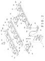
FIG. 2 is an exploded perspective view of one lateral half of the cable management device inFIG. 1 ; -
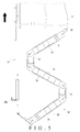
FIG. 3 is a top view of one lateral half of the cable management device inFIG. 1 ; -
FIG. 4 is a perspective view showing how support arms and a connecting member in the cable management device inFIG. 1 are mounted relative to one another; -
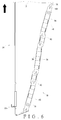
FIG. 5 is a schematic drawing in which one lateral half of the cable management device inFIG. 1 has been extended to a predetermined position; -
FIG. 6 is a schematic drawing in which one lateral half of the cable management device inFIG. 1 has been fully extended; -
FIG. 7 is a schematic drawing in which both lateral halves of the cable management device inFIG. 1 have been fully extended; and -
FIG. 8 is a perspective view in which the cable management device in another embodiment of the present invention is connected to a rack. -
FIG. 1 shows arack 10, achassis 12, a firstslide rail assembly 14, a secondslide rail assembly 16, and acable management device 18. Therack 10 includes afirst post 20a, asecond post 20b, athird post 20c, and afourth post 20d. Thefirst post 20a and thesecond post 20b correspond in position to thethird post 20c and thefourth post 20d respectively. Thechassis 12 has one lateral side mounted between thefirst post 20a and thesecond post 20b of therack 10 by means of the firstslide rail assembly 14. The opposite lateral side of thechassis 12 is mounted between thethird post 20c and thefourth post 20d of therack 10 by means of the secondslide rail assembly 16. Thecable management device 18 includes at least one cable management arm and preferably includes a firstcable management arm 22 and a secondcable management arm 24. The firstcable management arm 22 and the secondcable management arm 24 have substantially the same structural features. The firstcable management arm 22 is movably connected between thechassis 12 and the firstslide rail assembly 14. The secondcable management arm 24 is movably connected between thechassis 12 and the secondslide rail assembly 16. - In one preferred embodiment, a
first support member 26 is movably connected between thechassis 12 and the firstcable management arm 22, and asecond support member 28 is movably connected between the firstcable management arm 22 and the firstslide rail assembly 14. Similarly, athird support member 30 is movably connected between thechassis 12 and the secondcable management arm 24, and afourth support member 32 is movably connected between the secondcable management arm 24 and the secondslide rail assembly 16. Preferably, thefirst support member 26 and thethird support member 30 are respectively connected to thechassis 12 at positions adjacent to a rear middle part of thechassis 12. - The first cable management arm is now described in more detail with reference to
FIG. 2 andFIG. 3 . The first cable management arm includes afirst support arm 34, asecond support arm 36, athird support arm 38, a first connectingmember 40, and a second connectingmember 42. The first connectingmember 40 is movably connected between thefirst support arm 34 and thesecond support arm 36. The second connectingmember 42 is movably connected between thesecond support arm 36 and thethird support arm 38. - The
first support arm 34 includes afront portion 44a, arear portion 44b, afirst guiding portion 46a located at thefront portion 44a, asecond guiding portion 46b located at therear portion 44b, and a plurality ofcable management elements 48 for cable management. Thefirst guiding portion 46a and thesecond guiding portion 46b are configured in the same way. - The
second support arm 36 includes afront portion 50a, arear portion 50b, afirst guiding portion 52a located at thefront portion 50a, asecond guiding portion 52b located at therear portion 50b, and a plurality ofcable management elements 54 for cable management. Thefirst guiding portion 52a and thesecond guiding portion 52b are configured in the same way. - The
third support arm 38 includes afront portion 56a, arear portion 56b, afirst guiding portion 58a located at thefront portion 56a, asecond guiding portion 58b located at therear portion 56b, and a plurality ofcable management elements 60 for cable management. Thefirst guiding portion 58a and thesecond guiding portion 58b are configured in the same way. - The first connecting
member 40 is movably connected between thefirst support arm 34 and thesecond support arm 36. The first connectingmember 40 includes afront guiding portion 62a and arear guiding portion 62b. Preferably, the first connectingmember 40 is pivotally connected between thefirst support arm 34 and thesecond support arm 36 via a pair offirst pivot elements 41. - The second connecting
member 42 is movably connected between thesecond support arm 36 and thethird support arm 38. The second connectingmember 42 includes afront guiding portion 64a and arear guiding portion 64b. Preferably, the second connectingmember 42 is pivotally connected between thesecond support arm 36 and thethird support arm 38 via a pair ofsecond pivot elements 43. - More specifically, the
first support arm 34 is pivotally connected to thefirst support member 26 via athird pivot element 341, wherein thefirst support member 26 is connected to thechassis 12. Thethird support arm 38 is pivotally connected to thesecond support member 28 via afourth pivot element 381, and thesecond support member 28 is pivotally connected to the firstslide rail assembly 14 via afifth pivot element 281. Preferably, thesecond support member 28 has acurved groove 29 corresponding to thefirst guiding portion 58a of thethird support arm 38, and thefirst guiding portion 58a is a protruding block movable only within the limited space defined by thecurved groove 29. - As shown in
FIG. 4 , thefirst guiding portion 46a of thefirst support arm 34 can move along and relative to thefront guiding portion 62a of the first connectingmember 40, thefirst guiding portion 52a of thesecond support arm 36 can move along and relative to therear guiding portion 62b of the first connectingmember 40, and thefirst guiding portion 58a of thethird support arm 38 can move along and relative to thecurved groove 29 of thesecond support member 28. - In one preferred embodiment, each of the
front guiding portions rear guiding portions first guiding portions second guiding portions - It should be noted that the
front guiding portions rear guiding portions first guiding portions second guiding portions -
FIG. 5 andFIG. 6 show how thecable management device 18 operates. As shown inFIG. 5 , when thechassis 12 is pulled out from therack 10 by means of the slide rail assemblies (14, 16), thecable management device 18 is driven by thechassis 12 such that thefirst support arm 34, the first connectingmember 40, thesecond support arm 36, the second connectingmember 42, and thethird support arm 38 are extended due to the curved groove-and-protruding block connections therebetween. The same curved groove-and-protruding block connections also provide thecable management device 18 with guiding and position-limiting functions, which help maintain the extending direction of the cables received in thecable management elements FIG. 6 , thecable management device 18 is in a fully extended state.FIG. 7 shows that both lateral halves of thecable management device 18 depicted inFIG. 1 are in the fully extended state. - When the
chassis 12 is pushed back from outside of therack 10 by means of the slide rail assemblies (14, 16), the movable connection between thefirst support arm 34 and thefirst support member 26 of thechassis 12 allows thecable management device 18 to be driven by thechassis 12. In other words, thefirst support arm 34, the first connectingmember 40, thesecond support arm 36, the second connectingmember 42, and thethird support arm 38 will be folded due to the curved groove-and-protruding block connections therebetween. The same curved groove-and-protruding block connections also provide thecable management device 18 with guiding and position-limiting functions and help maintain the folding direction of the cables received in thecable management elements cable management device 18 is thus in the fully folded state as shown inFIG. 3 . -
FIG. 8 shows another embodiment in which thefront portion 56a of thethird support arm 38 of the firstcable management arm 22 is pivotally connected to thesecond post 20b of the rack via anextension member 66. Similarly, in the other lateral half of thecable management device 18 that is not shown in the drawing, the secondcable management arm 24 is pivotally connected to thefourth post 20d via another extension member. - While the present invention has been disclosed through the foregoing preferred embodiments, it is understood that the embodiments are not intended to restrict the scope of the present invention. The scope of the present invention is defined only by the appended claims.
Claims (11)
- A cable management device (18) applicable to a chassis (12) and comprising a first cable management arm (22), the first cable management arm (22) comprising:a first support arm (34) comprising a front portion (44a), a rear portion (44b), and a first guiding portion (46a) located at the front portion (44a) of the first support arm (34);a second support arm (36) comprising a front portion (50a), a rear portion (50b), and a first guiding portion (52a) located at the front portion (50a) of the second support arm (36); characterized in that the first cable management arm (22) further comprises:a first connecting member (40) movably connected between the front portion (44a) of the first support arm (34) and the front portion (50a) of the second support arm (36), the first connecting member (40) comprising a front guiding portion (62a) and a rear guiding portion (62b);wherein the first guiding portion (46a) of the first support arm (34) is movable along and relative to the front guiding portion (62a) of the first connecting member (40), and the first guiding portion (52a) of the second support arm (36) is movable along and relative to the rear guiding portion (62b) of the first connecting member (40).
- The cable management device (18) of claim 1, wherein each of the front guiding portion (62a) and the rear guiding portion (62b) of the first connecting member (40) is a curved groove, and each of the first guiding portion (46a) of the first support arm (34) and the first guiding portion (52a) of the second support arm (36) is a protruding block movable only within a limited space defined by a corresponding one of the curved grooves.
- The cable management device (18) of claim 2, wherein each of the curved grooves defines a path corresponding to a 90-degree circular arc.
- The cable management device (18) of claim 1, wherein the chassis (12) has a lateral side mounted to a rack (10) via a first slide rail assembly (14), the first support arm (34) further comprises a second guiding portion (46b) located at the rear portion (44b) of the first support arm (34), the second support arm (36) further comprises a second guiding portion (52b) located at the rear portion (50b) of the second support arm (36), and the first cable management arm (22) further comprises:a third support arm (38) comprising a front portion (56a), a rear portion (56b), a first guiding portion (58a) located at the front portion (56a) of the third support arm (38), and a second guiding portion (58b) located at the rear portion (56b) of the third support arm (38); anda second connecting member (42) movably connected between the rear portion (50b) of the second support arm (36) and the rear portion (56b) of the third support arm (38), the second connecting member (42) comprising a front guiding portion (64a) and a rear guiding portion (64b);wherein the rear portion (44b) of the first support arm (34) is movably connected to the chassis (12); the front portion (56a) of the third support arm (38) is movably connected to one of the first slide rail assembly (14) and the rack (10); and when the chassis (12) is pulled out from the rack (10) via the first slide rail assembly (14), the first guiding portion (46a) of the first support arm (34) is moved along and relative to the front guiding portion (62a) of the first connecting member (40), the first guiding portion (52a) of the second support arm (36) is moved along and relative to the rear guiding portion (62b) of the first connecting member (40), the second guiding portion (52b) of the second support arm (36) is moved along and relative to the front guiding portion (64a) of the second connecting member (42), and the second guiding portion (58b) of the third support arm (38) is moved along and relative to the rear guiding portion (64b) of the second connecting member (42) such that the first support arm (34), the first connecting member (40), the second support arm (36), the second connecting member (42), and the third support arm (38) are driven to an extended position.
- The cable management device (18) of claim 4, further comprising a first support member (26) and a second support member (28), wherein the first support member (26) is connected between the chassis (12) and the rear portion (44b) of the first support arm (34), and the second support member (28) is connected either between the first slide rail assembly (14) and the front portion (56a) of the third support arm (38) or between the rack (10) and the front portion (56a) of the third support arm (38).
- The cable management device (18) of claim 5, wherein the second support member (28) has a curved groove (29) corresponding to the first guiding portion (58a) of the third support arm (38), and the first guiding portion (58a) of the third support arm (38) is a protruding block movable only within a limited space defined by the curved groove (29).
- The cable management device (18) of claim 4, wherein the front guiding portions (62a, 64a) and the rear guiding portions (62b, 64b) of the first connecting member (40) and the second connecting member (42) are curved grooves; and the first guiding portion (46a) of the first support arm (34), the first guiding portion (52a) and the second guiding portion (52b) of the second support arm (36), and the second guiding portion (58b) of the third support arm (38) are protruding blocks respectively movable only within limited spaces respectively defined by the curved grooves.
- The cable management device (18) of claim 7, wherein each of the curved grooves defines a path corresponding to a 90-degree circular arc.
- The cable management device (18) of claim 1, wherein the chassis (12) is mounted to a rack (10) via a pair of slide rail assemblies (14, 16), the cable management device (18) further comprises a second cable management arm (24), the first support arm (34) further comprises a second guiding portion (46b) located at the rear portion (44b) of the first support arm (34), the second support arm (36) further comprises a second guiding portion (52b) located at the rear portion (50b) of the second support arm (36), and the first cable management arm (22) further comprises:a third support arm (38) comprising a front portion (56a), a rear portion (56b), a first guiding portion (58a) located at the front portion (56a) of the third support arm (38), and a second guiding portion (58b) located at the rear portion (56b) of the third support arm (38); anda second connecting member (42) movably connected between the rear portion (50b) of the second support arm (36) and the rear portion (56b) of the third support arm (38), the second connecting member (42) comprising a front guiding portion (64a) and a rear guiding portion (64b);wherein the rear portion (44b) of the first support arm (34) is movably connected to the chassis (12); the front portion (56a) of the third support arm (38) is movably connected to one of the slide rail assemblies (14, 16) or is movably connected to the rack (10); and when the chassis (12) is pulled out from the rack (10) via the slide rail assemblies (14, 16), the first guiding portion (46a) of the first support arm (34) is moved along and relative to the front guiding portion (62a) of the first connecting member (40), the first guiding portion (52a) of the second support arm (36) is moved along and relative to the rear guiding portion (62b) of the first connecting member (40), the second guiding portion (52b) of the second support arm (36) is moved along and relative to the front guiding portion (64a) of the second connecting member (42), and the second guiding portion (58b) of the third support arm (38) is moved along and relative to the rear guiding portion (64b) of the second connecting member (42) such that the first support arm (34), the first connecting member (40), the second support arm (36), the second connecting member (42), and the third support arm (38) are driven to an extended position.
- The cable management device (18) of claim 9, further comprising a first support member (26), a second support member (28), a third support member (30), and a fourth support member (32), wherein the first support member (26) is movably connected between the chassis (12) and the first cable management arm (22), the second support member (28) is movably connected between the first cable management arm (22) and one of the slide rail assemblies (14, 16), the third support member (30) is movably connected between the chassis (12) and the second cable management arm (24), and the fourth support member (32) is movably connected between the second cable management arm (24) and the other one of the slide rail assemblies (14, 16).
- The cable management device (18) of claim 10, wherein the first support member (26) and the third support member (30) are respectively connected to the chassis (12) at positions adjacent to a rear middle part of the chassis (12).
Priority Applications (1)
| Application Number | Priority Date | Filing Date | Title |
|---|---|---|---|
| EP14162032.8A EP2925103B1 (en) | 2014-03-27 | 2014-03-27 | Cable management device |
Applications Claiming Priority (1)
| Application Number | Priority Date | Filing Date | Title |
|---|---|---|---|
| EP14162032.8A EP2925103B1 (en) | 2014-03-27 | 2014-03-27 | Cable management device |
Publications (2)
| Publication Number | Publication Date |
|---|---|
| EP2925103A1 true EP2925103A1 (en) | 2015-09-30 |
| EP2925103B1 EP2925103B1 (en) | 2017-09-20 |
Family
ID=50382345
Family Applications (1)
| Application Number | Title | Priority Date | Filing Date |
|---|---|---|---|
| EP14162032.8A Active EP2925103B1 (en) | 2014-03-27 | 2014-03-27 | Cable management device |
Country Status (1)
| Country | Link |
|---|---|
| EP (1) | EP2925103B1 (en) |
Cited By (1)
| Publication number | Priority date | Publication date | Assignee | Title |
|---|---|---|---|---|
| EP3282713A1 (en) * | 2016-08-12 | 2018-02-14 | King Slide Works Co., Ltd. | Slide rail assembly and cable management device thereof |
Citations (3)
| Publication number | Priority date | Publication date | Assignee | Title |
|---|---|---|---|---|
| US20120312761A1 (en) * | 2011-06-13 | 2012-12-13 | James C. White Company, Inc. | Horizontal Cable Tray Redirector |
| US8379410B2 (en) | 2009-10-30 | 2013-02-19 | Dell Products L.P. | Reversible cable management arm |
| WO2013076855A1 (en) * | 2011-11-24 | 2013-05-30 | 富士通株式会社 | Cable management device and information processing device |
-
2014
- 2014-03-27 EP EP14162032.8A patent/EP2925103B1/en active Active
Patent Citations (3)
| Publication number | Priority date | Publication date | Assignee | Title |
|---|---|---|---|---|
| US8379410B2 (en) | 2009-10-30 | 2013-02-19 | Dell Products L.P. | Reversible cable management arm |
| US20120312761A1 (en) * | 2011-06-13 | 2012-12-13 | James C. White Company, Inc. | Horizontal Cable Tray Redirector |
| WO2013076855A1 (en) * | 2011-11-24 | 2013-05-30 | 富士通株式会社 | Cable management device and information processing device |
Cited By (1)
| Publication number | Priority date | Publication date | Assignee | Title |
|---|---|---|---|---|
| EP3282713A1 (en) * | 2016-08-12 | 2018-02-14 | King Slide Works Co., Ltd. | Slide rail assembly and cable management device thereof |
Also Published As
| Publication number | Publication date |
|---|---|
| EP2925103B1 (en) | 2017-09-20 |
Similar Documents
| Publication | Publication Date | Title |
|---|---|---|
| US9370121B2 (en) | Cable management device | |
| EP3442316B1 (en) | Cable management device and connecting assembly for rack system | |
| AU2006231625B2 (en) | Cable management bar and patch panel | |
| US9603277B2 (en) | Field-reconfigurable backplane system | |
| US8763206B1 (en) | Hinge | |
| EP3258755B1 (en) | Rack system | |
| US10018249B2 (en) | Device for guiding long object | |
| WO2011153360A1 (en) | Articulating mount for weapon sight accessory | |
| US7036187B2 (en) | Reinforcer for wrapped band friction hinges | |
| EP2899577A1 (en) | Lc optical fiber cable adapter assembly | |
| US10225945B2 (en) | Rack system and slide rail assemblies thereof | |
| WO2019051259A1 (en) | CLAMP | |
| US10707658B2 (en) | Stackable saddle of the perfected type for supporting elongated bodies | |
| CN109429465B (en) | Rack systems, cable management and connection assemblies | |
| WO2015096987A1 (en) | Headphone | |
| EP2925103B1 (en) | Cable management device | |
| US10023364B2 (en) | Hinge structure | |
| US7673835B2 (en) | Telescoping cover for cable trough system | |
| US9201199B2 (en) | One-piece optical fiber adapter | |
| US20110048439A1 (en) | Adjustable Comb | |
| EP3030065B1 (en) | Cable management arm supporting device and mounting assembly thereof | |
| CA2791892A1 (en) | Reinforcement bar positioning system | |
| TWI601470B (en) | Cable management device for a rack server | |
| JP6997826B2 (en) | Cable management assembly | |
| US20140041932A1 (en) | Cable holder devices, systems, and methods |
Legal Events
| Date | Code | Title | Description |
|---|---|---|---|
| PUAI | Public reference made under article 153(3) epc to a published international application that has entered the european phase |
Free format text: ORIGINAL CODE: 0009012 |
|
| 17P | Request for examination filed |
Effective date: 20150813 |
|
| AK | Designated contracting states |
Kind code of ref document: A1 Designated state(s): AL AT BE BG CH CY CZ DE DK EE ES FI FR GB GR HR HU IE IS IT LI LT LU LV MC MK MT NL NO PL PT RO RS SE SI SK SM TR |
|
| AX | Request for extension of the european patent |
Extension state: BA ME |
|
| GRAP | Despatch of communication of intention to grant a patent |
Free format text: ORIGINAL CODE: EPIDOSNIGR1 |
|
| RIC1 | Information provided on ipc code assigned before grant |
Ipc: H05K 7/14 20060101AFI20170309BHEP |
|
| INTG | Intention to grant announced |
Effective date: 20170412 |
|
| GRAS | Grant fee paid |
Free format text: ORIGINAL CODE: EPIDOSNIGR3 |
|
| GRAA | (expected) grant |
Free format text: ORIGINAL CODE: 0009210 |
|
| AK | Designated contracting states |
Kind code of ref document: B1 Designated state(s): AL AT BE BG CH CY CZ DE DK EE ES FI FR GB GR HR HU IE IS IT LI LT LU LV MC MK MT NL NO PL PT RO RS SE SI SK SM TR |
|
| REG | Reference to a national code |
Ref country code: GB Ref legal event code: FG4D |
|
| REG | Reference to a national code |
Ref country code: CH Ref legal event code: EP |
|
| REG | Reference to a national code |
Ref country code: AT Ref legal event code: REF Ref document number: 931093 Country of ref document: AT Kind code of ref document: T Effective date: 20171015 |
|
| REG | Reference to a national code |
Ref country code: IE Ref legal event code: FG4D |
|
| REG | Reference to a national code |
Ref country code: DE Ref legal event code: R096 Ref document number: 602014014726 Country of ref document: DE |
|
| REG | Reference to a national code |
Ref country code: NL Ref legal event code: MP Effective date: 20170920 |
|
| PG25 | Lapsed in a contracting state [announced via postgrant information from national office to epo] |
Ref country code: LT Free format text: LAPSE BECAUSE OF FAILURE TO SUBMIT A TRANSLATION OF THE DESCRIPTION OR TO PAY THE FEE WITHIN THE PRESCRIBED TIME-LIMIT Effective date: 20170920 Ref country code: HR Free format text: LAPSE BECAUSE OF FAILURE TO SUBMIT A TRANSLATION OF THE DESCRIPTION OR TO PAY THE FEE WITHIN THE PRESCRIBED TIME-LIMIT Effective date: 20170920 Ref country code: NO Free format text: LAPSE BECAUSE OF FAILURE TO SUBMIT A TRANSLATION OF THE DESCRIPTION OR TO PAY THE FEE WITHIN THE PRESCRIBED TIME-LIMIT Effective date: 20171220 Ref country code: FI Free format text: LAPSE BECAUSE OF FAILURE TO SUBMIT A TRANSLATION OF THE DESCRIPTION OR TO PAY THE FEE WITHIN THE PRESCRIBED TIME-LIMIT Effective date: 20170920 Ref country code: SE Free format text: LAPSE BECAUSE OF FAILURE TO SUBMIT A TRANSLATION OF THE DESCRIPTION OR TO PAY THE FEE WITHIN THE PRESCRIBED TIME-LIMIT Effective date: 20170920 |
|
| REG | Reference to a national code |
Ref country code: LT Ref legal event code: MG4D |
|
| REG | Reference to a national code |
Ref country code: AT Ref legal event code: MK05 Ref document number: 931093 Country of ref document: AT Kind code of ref document: T Effective date: 20170920 |
|
| PG25 | Lapsed in a contracting state [announced via postgrant information from national office to epo] |
Ref country code: RS Free format text: LAPSE BECAUSE OF FAILURE TO SUBMIT A TRANSLATION OF THE DESCRIPTION OR TO PAY THE FEE WITHIN THE PRESCRIBED TIME-LIMIT Effective date: 20170920 Ref country code: BG Free format text: LAPSE BECAUSE OF FAILURE TO SUBMIT A TRANSLATION OF THE DESCRIPTION OR TO PAY THE FEE WITHIN THE PRESCRIBED TIME-LIMIT Effective date: 20171220 Ref country code: LV Free format text: LAPSE BECAUSE OF FAILURE TO SUBMIT A TRANSLATION OF THE DESCRIPTION OR TO PAY THE FEE WITHIN THE PRESCRIBED TIME-LIMIT Effective date: 20170920 |
|
| PG25 | Lapsed in a contracting state [announced via postgrant information from national office to epo] |
Ref country code: NL Free format text: LAPSE BECAUSE OF FAILURE TO SUBMIT A TRANSLATION OF THE DESCRIPTION OR TO PAY THE FEE WITHIN THE PRESCRIBED TIME-LIMIT Effective date: 20170920 |
|
| PG25 | Lapsed in a contracting state [announced via postgrant information from national office to epo] |
Ref country code: CZ Free format text: LAPSE BECAUSE OF FAILURE TO SUBMIT A TRANSLATION OF THE DESCRIPTION OR TO PAY THE FEE WITHIN THE PRESCRIBED TIME-LIMIT Effective date: 20170920 Ref country code: RO Free format text: LAPSE BECAUSE OF FAILURE TO SUBMIT A TRANSLATION OF THE DESCRIPTION OR TO PAY THE FEE WITHIN THE PRESCRIBED TIME-LIMIT Effective date: 20170920 Ref country code: ES Free format text: LAPSE BECAUSE OF FAILURE TO SUBMIT A TRANSLATION OF THE DESCRIPTION OR TO PAY THE FEE WITHIN THE PRESCRIBED TIME-LIMIT Effective date: 20170920 Ref country code: PL Free format text: LAPSE BECAUSE OF FAILURE TO SUBMIT A TRANSLATION OF THE DESCRIPTION OR TO PAY THE FEE WITHIN THE PRESCRIBED TIME-LIMIT Effective date: 20170920 |
|
| PG25 | Lapsed in a contracting state [announced via postgrant information from national office to epo] |
Ref country code: AT Free format text: LAPSE BECAUSE OF FAILURE TO SUBMIT A TRANSLATION OF THE DESCRIPTION OR TO PAY THE FEE WITHIN THE PRESCRIBED TIME-LIMIT Effective date: 20170920 Ref country code: SM Free format text: LAPSE BECAUSE OF FAILURE TO SUBMIT A TRANSLATION OF THE DESCRIPTION OR TO PAY THE FEE WITHIN THE PRESCRIBED TIME-LIMIT Effective date: 20170920 Ref country code: EE Free format text: LAPSE BECAUSE OF FAILURE TO SUBMIT A TRANSLATION OF THE DESCRIPTION OR TO PAY THE FEE WITHIN THE PRESCRIBED TIME-LIMIT Effective date: 20170920 Ref country code: IT Free format text: LAPSE BECAUSE OF FAILURE TO SUBMIT A TRANSLATION OF THE DESCRIPTION OR TO PAY THE FEE WITHIN THE PRESCRIBED TIME-LIMIT Effective date: 20170920 Ref country code: IS Free format text: LAPSE BECAUSE OF FAILURE TO SUBMIT A TRANSLATION OF THE DESCRIPTION OR TO PAY THE FEE WITHIN THE PRESCRIBED TIME-LIMIT Effective date: 20180120 Ref country code: SK Free format text: LAPSE BECAUSE OF FAILURE TO SUBMIT A TRANSLATION OF THE DESCRIPTION OR TO PAY THE FEE WITHIN THE PRESCRIBED TIME-LIMIT Effective date: 20170920 |
|
| REG | Reference to a national code |
Ref country code: DE Ref legal event code: R097 Ref document number: 602014014726 Country of ref document: DE |
|
| PLBE | No opposition filed within time limit |
Free format text: ORIGINAL CODE: 0009261 |
|
| STAA | Information on the status of an ep patent application or granted ep patent |
Free format text: STATUS: NO OPPOSITION FILED WITHIN TIME LIMIT |
|
| PG25 | Lapsed in a contracting state [announced via postgrant information from national office to epo] |
Ref country code: DK Free format text: LAPSE BECAUSE OF FAILURE TO SUBMIT A TRANSLATION OF THE DESCRIPTION OR TO PAY THE FEE WITHIN THE PRESCRIBED TIME-LIMIT Effective date: 20170920 |
|
| 26N | No opposition filed |
Effective date: 20180621 |
|
| REG | Reference to a national code |
Ref country code: CH Ref legal event code: PL |
|
| PG25 | Lapsed in a contracting state [announced via postgrant information from national office to epo] |
Ref country code: MC Free format text: LAPSE BECAUSE OF FAILURE TO SUBMIT A TRANSLATION OF THE DESCRIPTION OR TO PAY THE FEE WITHIN THE PRESCRIBED TIME-LIMIT Effective date: 20170920 Ref country code: SI Free format text: LAPSE BECAUSE OF FAILURE TO SUBMIT A TRANSLATION OF THE DESCRIPTION OR TO PAY THE FEE WITHIN THE PRESCRIBED TIME-LIMIT Effective date: 20170920 |
|
| REG | Reference to a national code |
Ref country code: BE Ref legal event code: MM Effective date: 20180331 |
|
| PG25 | Lapsed in a contracting state [announced via postgrant information from national office to epo] |
Ref country code: LU Free format text: LAPSE BECAUSE OF NON-PAYMENT OF DUE FEES Effective date: 20180327 |
|
| PG25 | Lapsed in a contracting state [announced via postgrant information from national office to epo] |
Ref country code: LI Free format text: LAPSE BECAUSE OF NON-PAYMENT OF DUE FEES Effective date: 20180331 Ref country code: BE Free format text: LAPSE BECAUSE OF NON-PAYMENT OF DUE FEES Effective date: 20180331 Ref country code: CH Free format text: LAPSE BECAUSE OF NON-PAYMENT OF DUE FEES Effective date: 20180331 |
|
| PG25 | Lapsed in a contracting state [announced via postgrant information from national office to epo] |
Ref country code: FR Free format text: LAPSE BECAUSE OF NON-PAYMENT OF DUE FEES Effective date: 20180331 |
|
| PG25 | Lapsed in a contracting state [announced via postgrant information from national office to epo] |
Ref country code: MT Free format text: LAPSE BECAUSE OF NON-PAYMENT OF DUE FEES Effective date: 20180327 |
|
| PG25 | Lapsed in a contracting state [announced via postgrant information from national office to epo] |
Ref country code: TR Free format text: LAPSE BECAUSE OF FAILURE TO SUBMIT A TRANSLATION OF THE DESCRIPTION OR TO PAY THE FEE WITHIN THE PRESCRIBED TIME-LIMIT Effective date: 20170920 |
|
| PG25 | Lapsed in a contracting state [announced via postgrant information from national office to epo] |
Ref country code: PT Free format text: LAPSE BECAUSE OF FAILURE TO SUBMIT A TRANSLATION OF THE DESCRIPTION OR TO PAY THE FEE WITHIN THE PRESCRIBED TIME-LIMIT Effective date: 20170920 |
|
| PG25 | Lapsed in a contracting state [announced via postgrant information from national office to epo] |
Ref country code: MK Free format text: LAPSE BECAUSE OF NON-PAYMENT OF DUE FEES Effective date: 20170920 Ref country code: GR Free format text: LAPSE BECAUSE OF FAILURE TO SUBMIT A TRANSLATION OF THE DESCRIPTION OR TO PAY THE FEE WITHIN THE PRESCRIBED TIME-LIMIT Effective date: 20170920 Ref country code: CY Free format text: LAPSE BECAUSE OF FAILURE TO SUBMIT A TRANSLATION OF THE DESCRIPTION OR TO PAY THE FEE WITHIN THE PRESCRIBED TIME-LIMIT Effective date: 20170920 Ref country code: HU Free format text: LAPSE BECAUSE OF FAILURE TO SUBMIT A TRANSLATION OF THE DESCRIPTION OR TO PAY THE FEE WITHIN THE PRESCRIBED TIME-LIMIT; INVALID AB INITIO Effective date: 20140327 |
|
| PG25 | Lapsed in a contracting state [announced via postgrant information from national office to epo] |
Ref country code: AL Free format text: LAPSE BECAUSE OF FAILURE TO SUBMIT A TRANSLATION OF THE DESCRIPTION OR TO PAY THE FEE WITHIN THE PRESCRIBED TIME-LIMIT Effective date: 20170920 |
|
| PGFP | Annual fee paid to national office [announced via postgrant information from national office to epo] |
Ref country code: GB Payment date: 20260108 Year of fee payment: 13 |
|
| PGFP | Annual fee paid to national office [announced via postgrant information from national office to epo] |
Ref country code: IE Payment date: 20260108 Year of fee payment: 13 Ref country code: DE Payment date: 20260109 Year of fee payment: 13 |