EP2924855A1 - Slip ring structure - Google Patents
Slip ring structure Download PDFInfo
- Publication number
- EP2924855A1 EP2924855A1 EP13856241.8A EP13856241A EP2924855A1 EP 2924855 A1 EP2924855 A1 EP 2924855A1 EP 13856241 A EP13856241 A EP 13856241A EP 2924855 A1 EP2924855 A1 EP 2924855A1
- Authority
- EP
- European Patent Office
- Prior art keywords
- bus bars
- axial direction
- slip ring
- ring structure
- plate
- Prior art date
- Legal status (The legal status is an assumption and is not a legal conclusion. Google has not performed a legal analysis and makes no representation as to the accuracy of the status listed.)
- Withdrawn
Links
- 238000010276 construction Methods 0.000 description 13
- 239000011347 resin Substances 0.000 description 5
- 229920005989 resin Polymers 0.000 description 5
- 239000011162 core material Substances 0.000 description 4
- 238000000034 method Methods 0.000 description 4
- 230000005484 gravity Effects 0.000 description 2
- 238000012986 modification Methods 0.000 description 2
- 230000004048 modification Effects 0.000 description 2
- 230000004323 axial length Effects 0.000 description 1
- 238000007796 conventional method Methods 0.000 description 1
- 238000010141 design making Methods 0.000 description 1
- 230000000694 effects Effects 0.000 description 1
- 238000009413 insulation Methods 0.000 description 1
- 238000004519 manufacturing process Methods 0.000 description 1
- 239000002184 metal Substances 0.000 description 1
- 238000007493 shaping process Methods 0.000 description 1
Images



Classifications
-
- H—ELECTRICITY
- H01—ELECTRIC ELEMENTS
- H01R—ELECTRICALLY-CONDUCTIVE CONNECTIONS; STRUCTURAL ASSOCIATIONS OF A PLURALITY OF MUTUALLY-INSULATED ELECTRICAL CONNECTING ELEMENTS; COUPLING DEVICES; CURRENT COLLECTORS
- H01R39/00—Rotary current collectors, distributors or interrupters
- H01R39/02—Details for dynamo electric machines
- H01R39/08—Slip-rings
-
- H—ELECTRICITY
- H02—GENERATION; CONVERSION OR DISTRIBUTION OF ELECTRIC POWER
- H02K—DYNAMO-ELECTRIC MACHINES
- H02K13/00—Structural associations of current collectors with motors or generators, e.g. brush mounting plates or connections to windings; Disposition of current collectors in motors or generators; Arrangements for improving commutation
- H02K13/003—Structural associations of slip-rings
-
- H—ELECTRICITY
- H02—GENERATION; CONVERSION OR DISTRIBUTION OF ELECTRIC POWER
- H02K—DYNAMO-ELECTRIC MACHINES
- H02K13/00—Structural associations of current collectors with motors or generators, e.g. brush mounting plates or connections to windings; Disposition of current collectors in motors or generators; Arrangements for improving commutation
- H02K13/02—Connections between slip-rings and windings
-
- H—ELECTRICITY
- H02—GENERATION; CONVERSION OR DISTRIBUTION OF ELECTRIC POWER
- H02K—DYNAMO-ELECTRIC MACHINES
- H02K7/00—Arrangements for handling mechanical energy structurally associated with dynamo-electric machines, e.g. structural association with mechanical driving motors or auxiliary dynamo-electric machines
- H02K7/04—Balancing means
Definitions
- the present invention relates to a slip ring structure and in particular to one having a characteristic shape for a bus bar.
- slip rings are used in order to realize conductive contacts between a rotor and a stator.
- a bus bar is provided for the slip rings in respective phases.
- the bus bars in different phases have respectively different lengths, so they also have different weights. Accordingly, if the slip rings and bus bars for all phases are assembled together and rotated without any modification, their dynamic balance cannot be achieved.
- techniques for performing adjustment after assembling are known. For example, there is a method for shaping a portion of the shaft rotating integrally with the bus bars or a method for adding balancing weights in order to increase weight.
- Patent Document 1 describes a method for increasing weight by attaching "attached balancing members" to a rotor.
- Patent Document 1 Japanese Patent Application Laid-Open No. 7-163087
- the present invention is made in order to solve the problems and is aimed at providing a slip ring structure that facilitates the adjusting operation after assembly or makes it unnecessary.
- a slip ring structure related to the present invention comprises:
- Fig. 1 shows a partial construction of a motor 10 related to a first embodiment of the present invention.
- the motor 10 is a motor for three-phase alternating current and comprises a shaft 11 and a slip ring structure 20 constituting a rotor.
- the shaft 11 and the slip ring structure 20 can rotate integrally.
- the slip ring structure 20 includes slip rings 30U, 30V and 30W for three phases.
- the shaft 11 and the slip rings 30U, 30V and 30W are rotatable about a common axis.
- slip rings 30U, 30V and 30W contact brushes (not shown) and are electrically connected to an external component such as an inverter through the brushes to supply or receive three-phase alternating current.
- an inverter such as an inverter
- Those skilled in the art can design the construction of the motor 10 other than the slip ring structure 20 (e.g. coils) as needed, so explanation thereof is omitted here.
- Fig. 2 shows a partial construction of the slip ring structure 20.
- the slip ring structure 20 comprises the slip rings 30U, 30V and 30W for respective phases and bus bars 40U, 40V and 40W for respective phases.
- the slip ring 30U and the bus bar 40U correspond to U phase.
- the slip ring 30V and the bus bar 40V correspond to V phase.
- the slip ring 30W and the bus bar 40W correspond to W phase.
- the letters (U, V or W) at the end of reference signs for components represent their respective phases.
- the slip rings 30U, 30V and 30W have a common axis and are arranged at equal intervals in an axial direction.
- the bus bar 40W is connected to the slip ring 30W.
- the bus bar 40W comprises a plate-like portion 41W, a connecting portion 42W, a cylindrical portion 43W and a semi-cylindrical portion 44W and extends generally in an axial direction.
- the plate-like portion 41W, the cylindrical portion 43W and the semi-cylindrical portion 44W respectively extend in the axial direction.
- the cylindrical portion 43W and the semi-cylindrical portion 44W are aggregately referred to as a rod portion.
- the plate-like portion 41W has a plate-like structure of a rectangular or cylindrical-surface shape with a thickness.
- the plate like portion 41W connects the rod portion (in particular, the cylindrical portion 43W in this example) to the slip ring 30W through the connecting portion 42W.
- the cylindrical portion 43W is formed in a cylindrical shape.
- the semi-cylindrical portion 44W has a shape of a cylinder having the same diameter as the cylindrical portion 43W wherein a portion thereof is ground or shaved off by a plane parallel to the axis, i. e. a semi-cylinder-like shape.
- Screw holes 51 are provided perpendicular to the plane through the semi-cylindrical portion 44W. Wires or other conducting members are fixed to the screw holes 51 by screws 50 (see Fig. 1 ).
- the cylindrical portion 43W and the semi-cylindrical portion 44W extend in a range which does not overlap any of the slip rings 30U, 30V and 30W in an axial direction.
- the cylindrical portion 43W and the semi-cylindrical portion 44W extend rightward to the slip ring 30U which is arranged rightmost in the figure among the slip rings.
- the cylindrical portion 43W and the semi-cylindrical portion 44W are provided at the same circumferential position as the plate-like portion 41W but outward to the plate-like portion 41W in a radial direction.
- the connecting portion 42W has a predetermined dimension in a radial direction and connects the plate-like portion 41W and the cylindrical portion 43W.
- the bus bars 40U and 40V also have constructions similar to that of the bus bar 40W described above. However, axial positions of the slip rings are different among the phases, so lengths of the plate-like portions extending in the axial direction to contact the slip rings also differ accordingly among the phases. Further, thicknesses of the bus bars also differ among the phases. Differences among the phases, such as the above, will be explained later.
- Fig. 3 is a cross-sectional view of the slip ring structure 20 after being assembled taken along the cross section by the line III-III in Fig. 4.
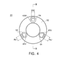
- Fig. 4 is a view of the slip ring structure 20 as seen from the direction of the arrow IV (i.e. from the side of semi-cylindrical portion in the axial direction) in Fig. 3 .
- the slip ring structure 20 comprises a core material 52 of metal and an insulating resin 53 for insulation.
- the core material 52 and the slip rings as well as the bus bars of respective phases are insulated by the insulating resin 53.
- the slip ring 30W contacts the bus bar 40W so that they are electrically conductive, whereas the slip ring 30W is insulated from the slip rings 30V and 30U by the insulating resin 53.
- the bus bars of respective phases are covered by the insulating resin 53 at one axial end (e.g. like the bus bar 40W in Fig. 3 ) but the other end is exposed passing through the core material 52.
- the regions around the bus bar 40W at axial ends of the portion where the bus bar 40W passes through the core material 52 are insulated from each other by an insulating collar 54 provided around the bus bar 40W.
- the insulating collar 54 also functions to prevent an O-ring from falling off. Note that the insulating collar 54 may be formed integral with the insulating resin 53.
- the plate-like portion 41W is the longest, the plate-like portion 41V is next longest and the plate-like portion 41U is the shortest.
- lengths of the rod portions of respective phases e.g. the length of the cylindrical portion 43W and the semi-cylindrical portion 44W together
- the total lengths of the bus bars differ depending on the lengths of the plate-like portions. That is, the bus bar 40W is the longest, the bus bar 40V is next longest and the bus bar 40U is the shortest.
- Thicknesses of the rod portions i.e. dimensions in a circumferential or radial direction
- a shorter bus bar has a greater diameter for the rod portion. That is, diameter RU of the cylindrical portion 43U and the semi-cylindrical portion 44U is greatest, diameter RV of the cylindrical portion 43V and the semi-cylindrical portion 44V is next greatest and diameter RW of the cylindrical portion 43W and the semi-cylindrical portion 44W is smallest.
- the thicknesses of the plate-like portions (i.e. dimensions in a circumferential or radial direction) of respective phases also differ among the phases.
- the circumferential dimensions (i.e. widths) of the plate-like portions of respective phases differ so that a shorter bus bar has a wider plate-like portion. That is, as shown in Fig. 5 for example, the plate-like portion 41U is widest, the plate-like portion 41V is next widest and the plate-like portion 41W is narrowest.
- one of the bus bars which has a shorter length in the axial direction, has a greater weight per unit axial length.
- weights of the bus bars 40U, 40V and 40W are equal.
- the slip rings 30U, 30V and 30W are constructed to be respectively rotationally symmetric or substantially rotationally symmetric and the bus bars 40U, 40V and 40W are constructed so that their centers of gravity are arranged at an equal or substantially equal distance from the rotation axis, making the weights of the bus bars equal to each other as described above would stabilize the dynamic balance when the slip ring structure 20 rotates integrally about the axis.
- the bus bars 40U, 40V and 40W are arranged at equal circumferential intervals on a circle centered on the axis in a cross section perpendicular to the axis.
- the bus bars are arranged to form angles of 120 degrees about the axis between each other. Such a construction can further stabilize the dynamic balance.
- the shape of the rod portions need not always be cylindrical or semi-cylindrical.
- they may be quadrangular-prismatic or another prismatic shape.
- they may be shapes having other cross sectional shapes.
- the bus bars can be constructed so that one of the bus bars which has a shorter length has a greater diameter for its rod portion.
- the rod portions have square-prismatic shapes, lengths of their diagonal lines can be defined as respective diameters.
- shapes of cross sections of the plate-like portion 41W, the cylindrical portion 43 and the semi-cylindrical portion 44W are respectively constant regardless of the axial positions of the cross sections.
- the shapes of the cross-sections may vary corresponding to their axial position. In such a case, if the bus bars are constructed so that one of the bus bars, which has a shorter length in the axial direction, has a greater cross sectional area in at least one position in the axial direction, the dynamic balance can be improved to some extent.
- the weights of the bus bars 40U, 40V and 40W are equal. However, they may also be unequal. Regardless of the total weights of the bus bars, if the bus bars are constructed so that one of the bus bars which has a shorter length has a greater weight per unit length, the dynamic balance can be improved to some extent compared with conventional slip ring structures.
- the slip ring structure 20 related to the first embodiment is for three-phase alternating current. However, a slip ring structure for two phases or more than or equal to four phases can be constructed in a similar manner.
Landscapes
- Engineering & Computer Science (AREA)
- Power Engineering (AREA)
- Manufacture Of Motors, Generators (AREA)
- Motor Or Generator Current Collectors (AREA)
Abstract
A slip ring structure for facilitating an adjusting operation after assembling is provided.
A slip ring structure 20 comprises slip rings 30U, 30V and 30W respectively provided to be rotatable about a common axis. The slip ring structure 20 comprises bus bars 40U, 40V and 40W connected to the slip rings 30U, 30V and 30W of the respective phases and extending in the axial direction. In at least one position in the axial direction, one of the bus bars, which has a shorter length in the axial direction, has a greater area in a cross section perpendicular to the axis.
Description
- The present invention relates to a slip ring structure and in particular to one having a characteristic shape for a bus bar.
- In an electrical rotating machine such as a motor, slip rings are used in order to realize conductive contacts between a rotor and a stator. A bus bar is provided for the slip rings in respective phases. However, the bus bars in different phases have respectively different lengths, so they also have different weights. Accordingly, if the slip rings and bus bars for all phases are assembled together and rotated without any modification, their dynamic balance cannot be achieved. In order to solve this, techniques for performing adjustment after assembling are known. For example, there is a method for shaping a portion of the shaft rotating integrally with the bus bars or a method for adding balancing weights in order to increase weight. Patent Document 1 describes a method for increasing weight by attaching "attached balancing members" to a rotor.
- [Patent Document 1] Japanese Patent Application Laid-Open No.
7-163087 - However, conventional techniques have problems in that an adjusting operation is required after assembly. For example, if a portion of the shaft is shaped or a balancing weight is attached, the overall shape would change. Also, if a design making room for adjustment is made, the total construction would be larger.
- The present invention is made in order to solve the problems and is aimed at providing a slip ring structure that facilitates the adjusting operation after assembly or makes it unnecessary.
- In order to solve the above problems, a slip ring structure related to the present invention comprises:
- slip rings for respective phases, respectively provided to be rotatable about a common axis; and
- bus bars connected to respective slip rings and extending in the axial direction, wherein
- In accordance with such a construction, imbalances caused due to differences in lengths of the bus bars are compensated by differences in thicknesses of the bus bars, so dynamic balance thereof is improved.
- In accordance with the slip ring structure of the present invention, imbalances caused due to differences in lengths of the bus bars is compensated by differences in thicknesses of the bus bars, so dynamic balance thereof is improved, thereby making the adjusting operation after assembly easier or unnecessary.
-
-
Fig. 1 shows a construction of a motor related to a first embodiment of the present invention. -
Fig. 2 shows a construction of the slip ring structure inFig. 1 . -
Fig. 3 is a cross-sectional view of a construction of the slip ring structure after being assembled. -
Fig. 4 is a view of the slip ring structure ofFig. 3 in the direction of the arrow IV. -
Fig. 5 shows examples of widths of plate-like portions. - Embodiments of the present invention will be explained below with reference to the attached drawings.
-
Fig. 1 shows a partial construction of amotor 10 related to a first embodiment of the present invention. Themotor 10 is a motor for three-phase alternating current and comprises ashaft 11 and aslip ring structure 20 constituting a rotor. Theshaft 11 and theslip ring structure 20 can rotate integrally. Theslip ring structure 20 includesslip rings shaft 11 and theslip rings - The
slip rings motor 10 other than the slip ring structure 20 (e.g. coils) as needed, so explanation thereof is omitted here. -
Fig. 2 shows a partial construction of theslip ring structure 20. Theslip ring structure 20 comprises theslip rings bus bars slip ring 30U and thebus bar 40U correspond to U phase. Theslip ring 30V and thebus bar 40V correspond to V phase. Theslip ring 30W and thebus bar 40W correspond to W phase. Similarly, in the following, the letters (U, V or W) at the end of reference signs for components represent their respective phases. - The
slip rings - The
bus bar 40W is connected to theslip ring 30W. Thebus bar 40W comprises a plate-like portion 41W, a connectingportion 42W, acylindrical portion 43W and asemi-cylindrical portion 44W and extends generally in an axial direction. In particular, the plate-like portion 41W, thecylindrical portion 43W and thesemi-cylindrical portion 44W respectively extend in the axial direction. Thecylindrical portion 43W and thesemi-cylindrical portion 44W are aggregately referred to as a rod portion. - The plate-
like portion 41W has a plate-like structure of a rectangular or cylindrical-surface shape with a thickness. The plate likeportion 41W connects the rod portion (in particular, thecylindrical portion 43W in this example) to theslip ring 30W through the connectingportion 42W. Thecylindrical portion 43W is formed in a cylindrical shape. Thesemi-cylindrical portion 44W has a shape of a cylinder having the same diameter as thecylindrical portion 43W wherein a portion thereof is ground or shaved off by a plane parallel to the axis, i. e. a semi-cylinder-like shape.Screw holes 51 are provided perpendicular to the plane through thesemi-cylindrical portion 44W. Wires or other conducting members are fixed to thescrew holes 51 by screws 50 (seeFig. 1 ). - The
cylindrical portion 43W and thesemi-cylindrical portion 44W extend in a range which does not overlap any of theslip rings Fig. 2 , thecylindrical portion 43W and thesemi-cylindrical portion 44W extend rightward to theslip ring 30U which is arranged rightmost in the figure among the slip rings. - The
cylindrical portion 43W and thesemi-cylindrical portion 44W are provided at the same circumferential position as the plate-like portion 41W but outward to the plate-like portion 41W in a radial direction. The connectingportion 42W has a predetermined dimension in a radial direction and connects the plate-like portion 41W and thecylindrical portion 43W. - The
bus bars bus bar 40W described above. However, axial positions of the slip rings are different among the phases, so lengths of the plate-like portions extending in the axial direction to contact the slip rings also differ accordingly among the phases. Further, thicknesses of the bus bars also differ among the phases. Differences among the phases, such as the above, will be explained later. - A construction of the
slip ring structure 20 after being assembled will be explained referring toFigs. 3 and4 . -
Fig. 3 is a cross-sectional view of theslip ring structure 20 after being assembled taken along the cross section by the line III-III inFig. 4. Fig. 4 is a view of theslip ring structure 20 as seen from the direction of the arrow IV (i.e. from the side of semi-cylindrical portion in the axial direction) inFig. 3 . - The
slip ring structure 20 comprises acore material 52 of metal and an insulatingresin 53 for insulation. Thecore material 52 and the slip rings as well as the bus bars of respective phases are insulated by the insulatingresin 53. Theslip ring 30W contacts thebus bar 40W so that they are electrically conductive, whereas theslip ring 30W is insulated from theslip rings resin 53. - The bus bars of respective phases are covered by the insulating
resin 53 at one axial end (e.g. like thebus bar 40W inFig. 3 ) but the other end is exposed passing through thecore material 52. The regions around thebus bar 40W at axial ends of the portion where thebus bar 40W passes through thecore material 52 are insulated from each other by an insulatingcollar 54 provided around thebus bar 40W. The insulatingcollar 54 also functions to prevent an O-ring from falling off. Note that the insulatingcollar 54 may be formed integral with the insulatingresin 53. - In the present embodiment, as shown in
Fig. 2 , if the plate-like portions of respective phases are looked at in terms of their lengths (i.e. in their axial dimensions), the plate-like portion 41W is the longest, the plate-like portion 41V is next longest and the plate-like portion 41U is the shortest. Also, lengths of the rod portions of respective phases (e.g. the length of thecylindrical portion 43W and thesemi-cylindrical portion 44W together) are equal or substantially equal. Accordingly, the total lengths of the bus bars differ depending on the lengths of the plate-like portions. That is, thebus bar 40W is the longest, thebus bar 40V is next longest and thebus bar 40U is the shortest. - Thicknesses of the rod portions (i.e. dimensions in a circumferential or radial direction) of respective phases also differ among the phases. In the present embodiment, as shown in
Figs. 2 and4 , a shorter bus bar has a greater diameter for the rod portion. That is, diameter RU of thecylindrical portion 43U and thesemi-cylindrical portion 44U is greatest, diameter RV of thecylindrical portion 43V and thesemi-cylindrical portion 44V is next greatest and diameter RW of thecylindrical portion 43W and thesemi-cylindrical portion 44W is smallest. - Further, the thicknesses of the plate-like portions (i.e. dimensions in a circumferential or radial direction) of respective phases also differ among the phases. In the example of
Fig. 2 , the circumferential dimensions (i.e. widths) of the plate-like portions of respective phases differ so that a shorter bus bar has a wider plate-like portion. That is, as shown inFig. 5 for example, the plate-like portion 41U is widest, the plate-like portion 41V is next widest and the plate-like portion 41W is narrowest. - According to the above construction, one of the bus bars, which has a shorter length in the axial direction, has a greater weight per unit axial length. In the present embodiment, weights of the bus bars 40U, 40V and 40W are equal. Here, if the slip rings 30U, 30V and 30W are constructed to be respectively rotationally symmetric or substantially rotationally symmetric and the bus bars 40U, 40V and 40W are constructed so that their centers of gravity are arranged at an equal or substantially equal distance from the rotation axis, making the weights of the bus bars equal to each other as described above would stabilize the dynamic balance when the
slip ring structure 20 rotates integrally about the axis. Also, in the present embodiment, the bus bars 40U, 40V and 40W are arranged at equal circumferential intervals on a circle centered on the axis in a cross section perpendicular to the axis. For example, inFig. 4 , the bus bars (more strictly, their centers of gravity) are arranged to form angles of 120 degrees about the axis between each other. Such a construction can further stabilize the dynamic balance. - As explained above, according to the
slip ring structure 20 relatedto the first embodiment of the present invention, imbalance caused due to differences in the lengths of the bus bars is compensated by differences in their thicknesses, so dynamic balance thereof is improved, thereby making the adjusting operation after assembly easier or unnecessary. Also, the room for adjustment would also be smaller or unnecessary. As a result, the total construction becomes compact so that manufacturing operations and cost are reduced. - The following modifications can be made to the above first embodiment.
- The shape of the rod portions (e.g. the
cylindrical portion 43W and thesemi-cylindrical portion 44W) need not always be cylindrical or semi-cylindrical. For example, they may be quadrangular-prismatic or another prismatic shape. Also, they may be shapes having other cross sectional shapes. Regardless of the shapes, if the cross sections of the bus bars for respective phases are constructed to be shapes wherein a dimension corresponding to "diameter" can be defined and so that the shapes are similar or substantially similar to each other, the bus bars can be constructed so that one of the bus bars which has a shorter length has a greater diameter for its rod portion. For example, if the rod portions have square-prismatic shapes, lengths of their diagonal lines can be defined as respective diameters. - In the first embodiment, for example regarding the
bus bar 40W, shapes of cross sections of the plate-like portion 41W, the cylindrical portion 43 and thesemi-cylindrical portion 44W are respectively constant regardless of the axial positions of the cross sections. In a variation, the shapes of the cross-sections may vary corresponding to their axial position. In such a case, if the bus bars are constructed so that one of the bus bars, which has a shorter length in the axial direction, has a greater cross sectional area in at least one position in the axial direction, the dynamic balance can be improved to some extent. - In the first embodiment, the weights of the bus bars 40U, 40V and 40W are equal. However, they may also be unequal. Regardless of the total weights of the bus bars, if the bus bars are constructed so that one of the bus bars which has a shorter length has a greater weight per unit length, the dynamic balance can be improved to some extent compared with conventional slip ring structures.
- The
slip ring structure 20 related to the first embodiment is for three-phase alternating current. However, a slip ring structure for two phases or more than or equal to four phases can be constructed in a similar manner.
Claims (4)
- A slip ring structure, comprising:- slip rings for respective phases, respectively provided to be rotatable about a common axis; and- bus bars connected to respective slip rings and extending in the axial direction, whereinin at least one position in the axial direction, one of the bus bars, which has a shorter length in the axial direction, has a greater cross sectional area perpendicular to the axis.
- The slip ring structure of Claim 1, wherein the one of the bus bars, which has the shorter length in the axial direction, has a greater weight per unit length in the axial direction.
- The slip ring structure of Claim 1, wherein:- the bus bars comprise respective plate-like portions and respective rod portions;- the plate-like portions and the rod portions extend in the axial direction;- the plate-like portions connect the rod portions of the corresponding phases to the slip rings of the corresponding phases;- the rod portions extend in a range which does not overlap any of the slip rings in the axial direction;- the one of the bus bars, which has the shorter length in the axial direction, has a greater circumferential dimension for the plate-like portion; and- the one of the bus bars, which has the shorter length in the axial direction, has a greater diameter for the rod portion.
- The slip ring structure of Claim 1, wherein the bus bars are arranged at equal circumferential intervals on a circle centered on the axis in a cross section perpendicular to the axis.
Applications Claiming Priority (2)
| Application Number | Priority Date | Filing Date | Title |
|---|---|---|---|
| JP2012253873A JP2014103759A (en) | 2012-11-20 | 2012-11-20 | Slip ring structure |
| PCT/JP2013/078325 WO2014080712A1 (en) | 2012-11-20 | 2013-10-18 | Slip ring structure |
Publications (1)
| Publication Number | Publication Date |
|---|---|
| EP2924855A1 true EP2924855A1 (en) | 2015-09-30 |
Family
ID=50775900
Family Applications (1)
| Application Number | Title | Priority Date | Filing Date |
|---|---|---|---|
| EP13856241.8A Withdrawn EP2924855A1 (en) | 2012-11-20 | 2013-10-18 | Slip ring structure |
Country Status (5)
| Country | Link |
|---|---|
| US (1) | US20150288120A1 (en) |
| EP (1) | EP2924855A1 (en) |
| JP (1) | JP2014103759A (en) |
| CN (1) | CN104782031A (en) |
| WO (1) | WO2014080712A1 (en) |
Families Citing this family (8)
| Publication number | Priority date | Publication date | Assignee | Title |
|---|---|---|---|---|
| KR101545567B1 (en) | 2014-08-01 | 2015-08-19 | 주식회사 유탑엔지니어링건축사사무소 | Rotate type outlet |
| CN106887783A (en) * | 2017-03-08 | 2017-06-23 | 深圳市晶沛电子有限公司 | A kind of conducting slip ring |
| CN109888986B (en) * | 2019-03-19 | 2021-01-29 | 苏州萨伯工业设计有限公司 | Liquid-electric hybrid power rotor device |
| KR102915174B1 (en) | 2019-10-15 | 2026-01-20 | 엘지이노텍 주식회사 | Motor |
| DE102020102891B4 (en) | 2020-02-05 | 2025-11-27 | Bayerische Motoren Werke Aktiengesellschaft | Electric machine and motor vehicle |
| JP7700712B2 (en) * | 2022-03-17 | 2025-07-01 | 株式会社明電舎 | Slip ring assembly and rotating electrical machine |
| KR102689297B1 (en) * | 2022-04-13 | 2024-07-29 | 에이치알에스코리아 주식회사 | Slip ring for vehicle |
| KR102689298B1 (en) * | 2022-04-13 | 2024-07-29 | 에이치알에스코리아 주식회사 | Slip ring for vehicle |
Family Cites Families (12)
| Publication number | Priority date | Publication date | Assignee | Title |
|---|---|---|---|---|
| US2551030A (en) * | 1949-05-11 | 1951-05-01 | Cleveland Electric Motor Compa | Slip ring assembly |
| DE1167969B (en) * | 1961-12-22 | 1964-04-16 | Bosch Gmbh Robert | Slip ring body with insulating hub and process for its manufacture |
| US3871488A (en) * | 1974-02-13 | 1975-03-18 | Daniel R Sabre | Rock drilling |
| ZA8233B (en) * | 1981-01-15 | 1982-11-24 | Lucas Industries Ltd | Sliding contact assemblies for rotary electric machines |
| DE3364660D1 (en) * | 1982-05-06 | 1986-09-04 | Lucas Ind Plc | Small diameter slip ring assemblies and their production |
| US4645962A (en) * | 1984-09-28 | 1987-02-24 | Rol Industries Inc. | Slip ring assembly and method of making |
| US4684179A (en) * | 1986-01-22 | 1987-08-04 | Freeman Jerry H | Slip ring assembly for method of making same |
| JPH07163087A (en) | 1993-12-08 | 1995-06-23 | Shinko Electric Co Ltd | Initial processing method for unbalance amount of motor rotor |
| JP3845952B2 (en) * | 1997-05-26 | 2006-11-15 | 株式会社デンソー | Rotating electric machine |
| JP3812456B2 (en) * | 2002-02-15 | 2006-08-23 | 株式会社デンソー | Slip ring device for vehicle alternator |
| JP2008013011A (en) * | 2006-07-05 | 2008-01-24 | Jtekt Corp | Steer-by-wire system |
| JP5680616B2 (en) * | 2012-12-04 | 2015-03-04 | トヨタ自動車株式会社 | Slip ring device |
-
2012
- 2012-11-20 JP JP2012253873A patent/JP2014103759A/en not_active Withdrawn
-
2013
- 2013-10-18 US US14/443,672 patent/US20150288120A1/en not_active Abandoned
- 2013-10-18 CN CN201380059656.4A patent/CN104782031A/en active Pending
- 2013-10-18 EP EP13856241.8A patent/EP2924855A1/en not_active Withdrawn
- 2013-10-18 WO PCT/JP2013/078325 patent/WO2014080712A1/en not_active Ceased
Non-Patent Citations (1)
| Title |
|---|
| See references of WO2014080712A1 * |
Also Published As
| Publication number | Publication date |
|---|---|
| WO2014080712A1 (en) | 2014-05-30 |
| CN104782031A (en) | 2015-07-15 |
| US20150288120A1 (en) | 2015-10-08 |
| JP2014103759A (en) | 2014-06-05 |
Similar Documents
| Publication | Publication Date | Title |
|---|---|---|
| US20150288120A1 (en) | Slip ring structure | |
| CN104518596B (en) | Electric rotating machine | |
| JP4353950B2 (en) | Rotating electric machine | |
| US20120286618A1 (en) | Electric machine rotor bar and method of making same | |
| US9712012B2 (en) | Rotary electric machine having armature windings with reduced width portions | |
| JP5502913B2 (en) | Rotating electric machine | |
| EP3041115B1 (en) | Stator assembly and motor comprising the same | |
| MX2014007372A (en) | Rotor for a line start permanent magnet machine. | |
| EP3309930B1 (en) | Segmented rotor for an asynchronous machine and an asynchronous machine having such a segmented rotor | |
| CN106849452B (en) | Rotor for slip ring motor and slip ring motor | |
| US12294254B2 (en) | Mechanical strength of connection of wound rotor generator/motor | |
| CN109217506B (en) | Rotor and motor | |
| WO2015174277A1 (en) | Rotating electric machine and method for manufacturing same | |
| EP1976097A2 (en) | Rotary electric machine | |
| WO2015171486A1 (en) | Lamination for a permanent magnet machine | |
| CN105743242B (en) | Cage induction motor and cage induction motor rotor | |
| KR20090124025A (en) | Rotor manufacturing method of squirrel cage induction motor | |
| US20150022036A1 (en) | Rotor with non-cylindrical surface for dynamoelectric machine | |
| JP5748878B2 (en) | Rotating electric machine | |
| US12095323B2 (en) | Motor, and coil used for same | |
| WO2013043498A1 (en) | Stator terminal block for a multi-phase electric machine | |
| CN105103416A (en) | Electric motor and electrical equipment with the same | |
| CN113950786B (en) | Stator for rotating electric machine | |
| US11081939B2 (en) | Shaft for a rotating electrical machine, and rotor and method for producing such a rotor | |
| US1545673A (en) | Damper winding |
Legal Events
| Date | Code | Title | Description |
|---|---|---|---|
| PUAI | Public reference made under article 153(3) epc to a published international application that has entered the european phase |
Free format text: ORIGINAL CODE: 0009012 |
|
| STAA | Information on the status of an ep patent application or granted ep patent |
Free format text: STATUS: THE APPLICATION HAS BEEN WITHDRAWN |
|
| 17P | Request for examination filed |
Effective date: 20150520 |
|
| AK | Designated contracting states |
Kind code of ref document: A1 Designated state(s): AL AT BE BG CH CY CZ DE DK EE ES FI FR GB GR HR HU IE IS IT LI LT LU LV MC MK MT NL NO PL PT RO RS SE SI SK SM TR |
|
| AX | Request for extension of the european patent |
Extension state: BA ME |
|
| 18W | Application withdrawn |
Effective date: 20150911 |