EP2924824A1 - Terminal for connecting busbars - Google Patents
Terminal for connecting busbars Download PDFInfo
- Publication number
- EP2924824A1 EP2924824A1 EP15159295.3A EP15159295A EP2924824A1 EP 2924824 A1 EP2924824 A1 EP 2924824A1 EP 15159295 A EP15159295 A EP 15159295A EP 2924824 A1 EP2924824 A1 EP 2924824A1
- Authority
- EP
- European Patent Office
- Prior art keywords
- face
- bus bar
- terminal
- thickness
- conductive body
- Prior art date
- Legal status (The legal status is an assumption and is not a legal conclusion. Google has not performed a legal analysis and makes no representation as to the accuracy of the status listed.)
- Withdrawn
Links
- 238000009434 installation Methods 0.000 claims abstract description 30
- 230000005489 elastic deformation Effects 0.000 claims description 10
- 238000003780 insertion Methods 0.000 description 19
- 230000037431 insertion Effects 0.000 description 19
- 230000000284 resting effect Effects 0.000 description 5
- RYGMFSIKBFXOCR-UHFFFAOYSA-N Copper Chemical compound [Cu] RYGMFSIKBFXOCR-UHFFFAOYSA-N 0.000 description 1
- 239000004020 conductor Substances 0.000 description 1
- 229910052802 copper Inorganic materials 0.000 description 1
- 239000010949 copper Substances 0.000 description 1
- 230000008878 coupling Effects 0.000 description 1
- 238000010168 coupling process Methods 0.000 description 1
- 238000005859 coupling reaction Methods 0.000 description 1
- 238000004519 manufacturing process Methods 0.000 description 1
- 239000000463 material Substances 0.000 description 1
- 238000012986 modification Methods 0.000 description 1
- 230000004048 modification Effects 0.000 description 1
Images




Classifications
-
- H—ELECTRICITY
- H02—GENERATION; CONVERSION OR DISTRIBUTION OF ELECTRIC POWER
- H02B—BOARDS, SUBSTATIONS OR SWITCHING ARRANGEMENTS FOR THE SUPPLY OR DISTRIBUTION OF ELECTRIC POWER
- H02B11/00—Switchgear having carriage withdrawable for isolation
- H02B11/02—Details
- H02B11/04—Isolating-contacts, e.g. mountings or shieldings
-
- H—ELECTRICITY
- H02—GENERATION; CONVERSION OR DISTRIBUTION OF ELECTRIC POWER
- H02B—BOARDS, SUBSTATIONS OR SWITCHING ARRANGEMENTS FOR THE SUPPLY OR DISTRIBUTION OF ELECTRIC POWER
- H02B1/00—Frameworks, boards, panels, desks, casings; Details of substations or switching arrangements
- H02B1/26—Casings; Parts thereof or accessories therefor
- H02B1/30—Cabinet-type casings; Parts thereof or accessories therefor
- H02B1/32—Mounting of devices therein
- H02B1/34—Racks
- H02B1/36—Racks with withdrawable units
Definitions
- the present description relates to a terminal for the connection to bus bars suitable for installation within a cabinet for an electrical switchboard.
- electrical switchboards also described by equivalent terms such as electrical panels or electrical cabinets or by similar definitions, for example electrical switchboards for the distribution of electrical energy or for automation, comprise a cabinet.
- the cabinet defines an internal space for the housing of one or more electrical and/or electronic devices such as electrical switching devices, control or protection devices, current transformers, etc.
- bus bars conducting distribution bars
- terminals are used for connecting to the bus bars in order to achieve an electrical connection between the bus bars themselves and the various electrical and/or electronic devices of the electrical switchboard.
- terminals of the type known in the art comprise a conductive body having a slot; the slot comprises a bottom wall from which protrude transversely, spaced apart and facing each other, a first side portion and a second side portion.
- the slot further comprises an opening facing towards the bottom wall such as to allow for the insertion of a bus bar towards the bottom wall thereof.
- the bus bar generally of a flat type, comprises a first face and a second face spaced apart by the thickness of the bar itself, and its insertion into the slot takes place with the first face and the second face facing the first side portion and the second side portion, respectively, of the slot.
- the first side portion and second side portion comprise only a first surface and a second surface, respectively, which are suitable for contacting with the first face and the second face, in order to clamp the bus bar.
- the terminal is only able to connect to a particular type of bus bar, i.e. to bus bars having the same thickness between the first face and the second face.
- various electrical and/or electronic devices of the electrical switchboard are installed within the cabinet by means of one or more installation modules; the installation modules are generally configured as drawers that can be re-movably inserted into the cabinet, wherein electrical and/or electronic devices can be mounted.
- one or more electrical switching devices such as circuit breakers and the various devices associated therewith such as transformers or multimeters, can be mounted on the installation module.
- Each installation module comprises terminals, of the type known in the art and described above, which are connected to various electrical and/or electronic devices that are mounted within the installation module and which are suitable for connecting to corresponding bus bars of the cabinet.
- an installation module is first used to connect to a bus bar system having a certain thickness and that must subsequently be used to connect to a different bus bar system having a different thickness, it is then necessary to replace the terminals of the installation module or else to use a new installation module having different terminals of the known type which are suitable for connecting to and clamping the new bars.
- the terminal comprises a conductive body having a slot comprising:
- the first bus bar comprises at least a first face and a second face which are spaced apart by a first thickness.
- the first side portion and the second side portion comprise a first surface and a second surface, respectively, suitable for contacting the first face and the second face, respectively, in such a way as to clamp the first bus bar.
- At least a second bus bar can be inserted along the slot through the opening; such a second bus bar comprising at least a third face and a fourth face spaced apart by a second thickness that is sized differently than the first thickness.
- the first side portion and the second side portion comprise at least a third and a fourth surface respectively, that are suitable for contacting with the third face and the fourth face, respectively, in such a way as to clamp the second bus bar.
- a further aspect of the present description is that of providing a module for installing one or more electrical and/or electronic devices within an electrical switchboard cabinet; this module comprises at least one terminal as per the terminal defined in the appended claims and discussed in the following description.
- a further aspect of the present description is to provide an electrical switchboard comprising at least one terminal and/or one installation module such as the terminal and the installation module defined in the appended claims and discussed in the following description.
- transverse or “transversely” is employed in the following description it means a direction that is not parallel to the element or the direction to which said element refers, and the perpendicularity must be considered as a specific case of a transverse direction.
- the present description relates to a terminal 1 for the connection to bus bars 100, 101 suitable for the installation within a cabinet 200 for an electrical switchboard, in order to distribute electrical energy to electrical and/or electronic devices of the electrical switchboard.
- the terminal 1 comprises a conductive body 2, preferably made of a highly conductive material, such as copper.
- the conductive body 2 comprises a slot 10, which in turn comprises:
- At least one bus bar 100 can be inserted along the slot 10 through the opening 14; such a bus bar 100 comprising at least a face 102 and a face 103, and having a thickness T 1 separating the faces 102 and 103.
- the opening 14 is suitable for the removable insertion of the bus bar 100 along a respective portion of the slot 10, towards the bottom portion 11, so that the face 102 and the face 103 point towards the side portion 12 and the side portion 13, respectively.
- the side portion 12 and the side portion 13 of the slot 10 comprise a surface 22 and a surface 23, respectively, which are suitable for contacting with the face 102 and the face 103, respectively, in order to clamp the bus bar 100.
- the clamping produced by the contact between the surfaces 22 and 23 and the respective faces 102 and 103 of the bus bar 100 occurs along a direction that transversely links the first and second side portions 12 and 13 of the slot 10, i.e. along a direction that is transverse to the direction of insertion of the bus bar 100 within the slot 10.
- the bus bar 100 remains free to be removed from the slot 10 through the opening 14 between the side portions 12 and 13.
- the surfaces 22 and 23 are defined along the respective side portions 12 and 13 of the slot 10 with each facing towards the other.
- the conductive body 2 of the terminal 1 comprises a substantially flat portion 3.
- the conductive body 2 further comprises an edge 32 and an edge 33 having a thickness that is greater than the thickness of the flat portion 3.
- edges 32 and 33 are advantageously arranged with respect to the flat portion 3 in such a way as to define the surface 22 and the surface 23, respectively. Given that the edges 32 and 33 have a thickness that is greater than the flat portion 3, the surfaces 22 and 23 defined thereby have a greater contact area with respect to the bus bar 100, further improving the clamping of the bar 100.
- At least one bus bar 101 can also be inserted along the slot 10 through the opening 14; such bus bar 101 comprises at least a face 104 and a face 105, and has a thickness T 2 that spaces apart the faces 104 and 105 and that is sized differently with respect to the thickness T 1 of the bus bar 100.
- the opening 14 is also suitable for the removable insertion of the bus bar 101 along a respective portion of the slot 10, towards the bottom portion 11, such that the face 104 and the face 105 point towards the side portion 12 and the side portion 13, respectively.
- the side portion 12 and the side portion 13 of the slot 10 advantageously comprise a surface 24 and a surface 25, respectively, which are suitable for contacting the face 104 and the face 105, respectively, in order to clamp the bus bar 101.
- the clamping produced by the contact between the surfaces 24 and 25 and the respective faces 104 and 105 of the bus bar 101 occurs along a direction that transversely links the first and second side portions 12 and 13 of the slot 10, i.e. along a direction that is transverse to the direction of insertion of the bus bar 101 within the slot 10.
- the bus bar 101 remains free to be removed from the slot 10 through the opening 14 between the side portions 12 and 13.
- the surfaces 24 and 25 are defined along the respective side portions 12 and 13 of the slot 10 with each facing towards the other.
- the conductive body 2 of the terminal 1 further comprises an edge 34 and an edge 35 that feature a thickness that is greater than the thickness of the flat portion 3.
- edges 34 and 35 are advantageously arranged with respect to the flat portion 3 in such a way as to define the surface 24 and the surface 25, respectively.
- the edges 34 and 35 feature a thickness that is greater than the flat portion 3, the surfaces 24 and 25 thus defined feature a greater extent of contact area with respect to the bus bar 101, further improving the clamping of the bar 101.
- the conductive body 2 of the terminal 1 is suitable for deforming itself due to the contact between the surfaces 22 and 23 with the respective faces 102 and 103 of the bus bar 100, or due to the contact between the surfaces 24 and 25 with the respective faces 104 and 105 of the bus bar 101.
- the surfaces 22 and 23 are pointing towards each other and spaced apart in such a way that an insertion of the bus bar 100 between them, in order to cause their contact with the respective faces 102 and 103, causes a mutual moving away of the surfaces 22 and 23 and, therefore, of the portions 12 and 13 of the slot 10.
- the surfaces 24 and 25 are facing each other and spaced apart in such a way that an insertion of the bus bar 101 between them, in order to cause the contact with the respective faces 104 and 105, will induce a mutual moving away of the surfaces 24 and 25 and, therefore, of the portions 12 and 13 of the slot 10.
- the conductive body 2 Given that the conductive body 2 has its own elasticity, it will produce a force in order to return to the resting configuration, such force is:
- an elastic element 50 is operatively coupled to the conductive body 2 in such a way as to undergo a first elastic deformation caused by the deformation of the conductive body 2 due to the contact between the surfaces 22 and 23 with the bus bar 100, or a second elastic deformation caused by the deformation of the conductive body 2 due to the contact between the surfaces 24 and 25 with the bus bar 101.
- the elastic element 50 is operatively coupled to the conductive body 2 in such a way as to exert:
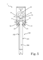
- the first clamping force comprises two components (both illustrated in figure 5 with the reference F 1 ), one directed towards and acting upon the face 102 and the other directed towards and acting upon the face 103 of the bus bar 100 clamped between the surfaces 22 and 23.
- the second clamping force comprises two components (both illustrated in figure 6 with the reference F 2 ), one directed towards and acting upon the face 104 and the other directed towards and acting upon the face 105 of the bus bar 101 clamped between the surfaces 24 and 25.
- the bus bar 100 which can be inserted through the opening 14, is flat, and has a longitudinal extension along a main axis 500.
- the face 102 and the face 103 are the surfaces with the greatest extension of the bus bar 100 extending parallel to each other along the main axis 500, and the thickness T 1 corresponds to the distance between these faces 102 and 103.
- the bus bar 101 which can be inserted through the opening 14 is flat, and has a longitudinal extension along a main axis 501.
- the face 104 and the face 105 are the surfaces with the greatest extension of the bus bar 100 extending parallel to each other along the main axis 501, and the thickness T 2 corresponds to the distance between these faces 104 and 105.
- the thickness T 2 is less than the thickness T 1 ; for example, the thickness T 1 of the flat bus bar 100 illustrated in figure 5 and the thickness T 2 of the flat bus bar 101 illustrated in figure 6 may have a size of 10mm and 5mm respectively.
- the cross-section with respect to the main axis 501 of the flat bus bar 101 is less than the cross-section with respect to the main axis 500 of the bus bar 100.
- the bus bar 100 is therefore sized to carry a greater nominal operating current greater than the bus bar 101.
- the surface 24 is positioned along the slot 10 between the bottom portion 11 and the surface 22, while the surface 25 is arranged along the slot 10 between the bottom portion 11 and the surface 23.
- the surfaces 24 and 25 are defined along the respective side portions 12 and 13 closer to the bottom portion 11 with respect to the surfaces 22 and 23, which are instead arranged closer to the opening 14 of the slot 10.
- edges 32 and 33 protrude from the flat portion 3 of the conductive body 2 in such a way as to define the corresponding surfaces 22 and 23 facing one another.
- the edge 34 protrudes with respect to the flat portion 3 at the side portion 12 of the slot 10, and is arranged between the bottom portion 11 and the edge 32; the edge 35 protrudes with respect to the flat portion 3 at the side portion 13 of the slot 10, and is arranged between the bottom portion 11 and the edge 33.
- the edges 34 and 35 protrude with respect to the flat portion 3 in such a way as to define the corresponding surfaces 24 facing one another.
- the conductive body 2 of the terminal 1 is manufactured as a single piece, wherein the edges 32, 33, 34 and 35 are portions that are bent, during manufacture, with respect to the flat portion 3.
- the edge 32 and the edge 33 comprise an end 36 and an end 37, respectively, having a curved portion to facilitate the insertion of the bus bar 100 into the slot 10, between the surfaces 22 and 23.
- the edge 34 and the edge 35 comprise an end 38 and an end 39, respectively, having a curved portion to facilitate the insertion of the bus bar 101 into the slot 10, between the surfaces 24 and 25.
- the illustrated flat bus bar 100 can therefore be inserted in the slot 10 through the opening 14, along an initial section of the slot 10, between the opening 14 and the edges 34 and 35.
- the surfaces 22 and 23 are defined by the edges 32 and 33 in such a way that, during insertion along the slot 10, the bus bar 100 is inserted between surfaces 22 and 23.
- the surfaces 22 and 23 are suitable for contacting in a sliding manner with the respective faces 102 and 103 of the bus bar 100, during insertion between them of such a bus bar 100.
- the surfaces 22 and 23 are suitable for remaining into contact with the faces 102 and 103, so as to clamp the bus bar 100 inserted between them along a direction that transversely links the surfaces 22 and 23.
- the terminal 1 comprises, as an elastic element 50, a spring 50 of a substantially "U" shape, having two side portions 51 and 52.
- This spring 50 is operatively coupled to the flat portion 3 of the conductive body 2 in such a way that the side portions 12 and 13 of the slot 10 are arranged between the side portions 51 and 52 of the spring 50.
- the minimum distance D 1 between the surfaces 22 and 23 is such that contact between the faces 102 and 103 of the bus bar 100 with the respective surfaces 22 and 23 causes the deformation of the conductive body 2; in particular, the minimum distance D 1 is sized in such a way as to be slightly less than the thickness T 1 of the bus bar 100. For example, for a bus bar 100 having a thickness T 1 of 10 mm, the minimum distance D 1 could be sized in such a way as to be equal to around 9.8 mm.
- the deformation of the conductive body 2 is such that the side portions 12 and 13 of the slot 10 move apart and, therefore, the side portions 51 and 52 of the spring 50 also move apart.
- the deformed spring 50 is suitable for applying, by means of the surfaces 22 and 23, the two components F 1 of the clamping force against the bus bar 100.
- the illustrated flat bus bar 101 can be inserted into the slot 10 through the opening 14, proceeding beyond the initial section which is accessible to the bus bar 100, in order to reach and insert between the surfaces 24 and 25 defined by the edges 34 and 35.
- the surfaces 24 and 25 are suitable for contacting in a sliding manner with the respective faces 104 and 105 of the bus bar 101, during insertion between them of such a bus bar 101.
- the surfaces 24 and 25 are suitable for remaining into contact with the faces 104 and 105, so as to clamp the bus bar 101 inserted between them along a direction that transversely links the surfaces 24 and 25.
- the minimum distance D 2 between the surfaces 24 and 25 is such that contact between the faces 104 and 105 of the bus bar 101 with the respective surfaces 24 and 25 causes the deformation of the conductive body 2; in particular, the minimum distance D 2 is sized in such a way as to be slightly less than the thickness T 2 of the bus bar 101. For example, for a bus bar 101 having a thickness T 2 of 5 mm, the minimum distance D 2 could be sized in such a way as to be equal to around 4.8 mm.
- the deformation of the conductive body 2 is such that the side portions 12 and 13 of the slot 10 move apart and, therefore, the side portions 51 and 52 of the spring 50 also move apart.
- the deformed spring 50 is suitable for applying, by means of the surfaces 24 and 25, the two components F 2 of the clamping force against the bus bar 101.
- the bus bar 100 enters into the slot 10 through the opening 14 and is inserted between the surfaces 22 and 23 of the edges 32 and 33, until reaching a final position within the slot 10, such as the final position illustrated for example in figure 5 .
- the bus bar 100 is clamped between the surfaces 22 and 23 of the edges 32 and 33, and the surfaces 22 and 23 remain in contact with the respective faces 102 and 103.
- the side portions 51 and 52 of the elastically deformed spring 50 apply a force for returning the spring 50 itself, together with the conductive body 2 of the terminal 1, to their respective resting positions.
- the side portions 51 and 52 by means of the surfaces 22 and 23, apply the components of the force F 1 which, as illustrated in figure 5 , are directed in such a way as to contribute to the clamping of the bus bar 100 between the surfaces 22 and 23.
- the terminal 1 can then be moved with respect to the clamped bus bar 100, in such a way that the surfaces 22 and 23 lose contact with the respective faces 102 and 103 of the bus bar 100.
- the spring 50 and the conductive body 2 of the terminal 1 return to their respective resting positions. At this point, the same terminal 1 can be re-connected to a corresponding bus bar 100 or 101.
- the terminal 1 can be connected to the bus bar 101 having a thickness T 2 which is less than the thickness T 1 of the bus bar 100.
- the bus bar 101 enters into the slot 10 through the opening 14 and is inserted between the surfaces 24 and 25 of the edges 34 and 35, until reaching a final position within the slot 10, such as the final position illustrated for example in figure 6 .
- the bus bar 101 is clamped between the surfaces 24 and 25 of the edges 32 and 33, and the surfaces 34 and 35 remain in contact with the faces 104 and 105.
- the side portions 51 and 52 of the elastically deformed spring 50 apply a force for returning the spring 50 itself, together with the conductive body 2 of the terminal 1, to their respective resting positions.
- the side portions 51 and 52 by means of the surfaces 24 and 25, apply the components of the force F 2 which, as illustrated in figure 6 , are directed in such a way as to contribute to the clamping of the bus bar 101 between the surfaces 24 and 25.
- the terminal 1 can then be moved with respect to the clamped bus bar 100, in such a way that the surfaces 24 and 25 lose contact with the respective faces 104 and 105 of the bus bar 101. Upon such a loss of contact, the spring 50 and the conductive body 2 of the terminal 1 return to their respective resting positions.
- This installation module 150 comprises at least one terminal 1 as previously described and claimed in the appended claims.
- the installation module 150 is suitable for electrically connecting one or more electrical and/or electronic devices 250, 251 thereon operatively mounted to the respective bus bars 100, 101 installed within the cabinet 200.
- the installation module 150 comprises one or more terminals 1 which are connected to the electrical and/or electronic devices 250, 251 and which can be connected, according to the previous description, to the respective bus bars 100, 101.
- the installation module 150 is in practice configured as a drawer 150 having a bottom wall 151 wherein one or more electrical and/or electronic components 250, 251 are mounted.
- the example installation module 150 illustrated in figures 7 and 8 is designed to be installed within the cabinet 200 of a low voltage distribution electrical switchboard, and on its bottom wall 251 there are operatively connected at least one circuit breaker 250 and one digital multimeter 251.
- connection means 255 the circuit breaker 250 and the digital multimeter 251 are connected, via connection means 255, to terminals 1 of the type previously described and illustrated in figures 1-6 .
- terminals 1 are accessible from the rear with respect to the bottom wall 151, in such a way as to connect to the respective bus bars 100 or 101, upon the insertion of the installation module 150 within the cabinet 200.
- figure 9 illustrates a cabinet 200 for a low-voltage electrical switchboard within which a plurality of bus bars 100 is installed, such as the bus bar 100 illustrated in figure 5 .
- Figure 9 also illustrates the installation module 150 of figures 7 and 8 which is inserted within the cabinet 200 in such a way that each of its terminals 1 is connected to one of the respective bars 100, according to the description given above.
- each of the terminals 1 of the installation module 150 can also be connected to a respective bus bar 101, having a thickness T 2 which is less than the thickness T 1 of the bus bar 100, as previously described.
- the terminal 1 In practice, it has been shown that the terminal 1 according to the present description allows the desired goal to be achieved by offering various improvements when compared with known solutions.
- the terminal 1 is suitable for connecting to and clamping bus bars 100, 101 featuring differently sized thicknesses T 1 and T 2 respectively.
- the terminal 1 achieves greater versatility in use which implies a series of advantages, amongst which are the following:
- such a module 150 may advantageously:
- the terminal 1 comprises only:
- the terminal 1 illustrated in figures 1-6 is suitable for contacting and clamping only two types of bars 100, 101 having differently sized thicknesses T 1 and T 2 respectively.
- the side portion 12 and the side portion 13 of the slot 10 of the terminal 1 may comprise at least an additional first surface and an additional second surface, respectively, which are suitable for contacting the opposite faces of an additional bus bar that can be inserted along the slot 10 through the opening 14, in such a way as to clamp this additional bus bar.
- these opposite faces of the additional bus bar would be spaced apart by a thickness that is sized differently with respect to the thicknesses T 1 and T 2 of the bus bars 100 and 101.
- the first additional surface could be defined along the side portion 12 of the slot 10 in such a way as to be arranged between the bottom portion 11 and the surface 24, and the second additional surface could be defined along the side portion 13 in such a way as to be arranged between the bottom portion 11 and the surface 25.
- the first and second additional surfaces are defined in such a way as to come in to contact with and clamp a bus bar having a thickness which is less than the thicknesses T 1 and T 2 of the bus bars 100 and 101.
- the first additional surface could be defined along the side portion 12 of the slot 10 in such a way that the surface 22 may be positioned between the surface 24 and the additional first surface
- the second additional surface could be defined along the side portion 13 in such a way that the surface 23 may be positioned between the surface 25 and the additional second surface.
- the first and second additional surfaces are defined in such a way as to come into contact with and clamp a bus bar having a thickness that is greater than the thicknesses T 1 and T 2 of the bus bars 100 and 101.
- the terminal 1 is suitable for contacting and clamp three types of bars each having different thicknesses.
- the terminal 1 is suitable for contacting and clamping a plurality of bars having different thicknesses between them, as far as for each bar of this plurality a pair of surfaces is defined along the side portions 12, 13 of the slot 10, each pair of surfaces being suitable for contacting and clamping the opposite faces of the bar.
- edges 32, 33, 34 and 35 have an equally sized thickness
- one or more of these edges 32-35 may be sized differently with respect to the others; for example, the edges 32 and 33 which define the surfaces 22 and 23 may have a thickness which is sized differently in comparison to the thicknesses of the edges 34 and 35 which define the surfaces 24 and 25.
Landscapes
- Engineering & Computer Science (AREA)
- Power Engineering (AREA)
- Connections Arranged To Contact A Plurality Of Conductors (AREA)
- Patch Boards (AREA)
- Connector Housings Or Holding Contact Members (AREA)
- Installation Of Bus-Bars (AREA)
Abstract
- a bottom portion;
- a first side portion and a second side portion that protrude transversely from the bottom portion, spaced apart and facing each other; and
- an opening facing the bottom portion, through which a first bus bar can be inserted along the slot.
Description
- The present description relates to a terminal for the connection to bus bars suitable for installation within a cabinet for an electrical switchboard.
- As already known in the art electrical switchboards, also described by equivalent terms such as electrical panels or electrical cabinets or by similar definitions, for example electrical switchboards for the distribution of electrical energy or for automation, comprise a cabinet.
- The cabinet defines an internal space for the housing of one or more electrical and/or electronic devices such as electrical switching devices, control or protection devices, current transformers, etc.
- It is also known that amongst the elements housed within the cabinet there are conducting distribution bars (hereinafter "bus bars") which are used to distribute electrical energy to the electrical and/or electronic devices of the electrical switchboard itself.
- In general, terminals are used for connecting to the bus bars in order to achieve an electrical connection between the bus bars themselves and the various electrical and/or electronic devices of the electrical switchboard.
- In particular, terminals of the type known in the art comprise a conductive body having a slot; the slot comprises a bottom wall from which protrude transversely, spaced apart and facing each other, a first side portion and a second side portion. The slot further comprises an opening facing towards the bottom wall such as to allow for the insertion of a bus bar towards the bottom wall thereof.
- In particular, the bus bar, generally of a flat type, comprises a first face and a second face spaced apart by the thickness of the bar itself, and its insertion into the slot takes place with the first face and the second face facing the first side portion and the second side portion, respectively, of the slot.
- The first side portion and second side portion comprise only a first surface and a second surface, respectively, which are suitable for contacting with the first face and the second face, in order to clamp the bus bar.
- According to this known solution, the terminal is only able to connect to a particular type of bus bar, i.e. to bus bars having the same thickness between the first face and the second face.
- Therefore, whenever bus bars installed within a cabinet are replaced with other bus bars having a different thickness, also the corresponding terminals must be appropriately replaced with different terminals, in particular with terminals having first and second surfaces that are suitable for contacting and for clamping the new bars.
- According to a known exemplary application, various electrical and/or electronic devices of the electrical switchboard are installed within the cabinet by means of one or more installation modules; the installation modules are generally configured as drawers that can be re-movably inserted into the cabinet, wherein electrical and/or electronic devices can be mounted.
- For example, in the case of an electrical distribution switchboard for low voltage applications, i.e. for operating voltages up to 1kV, one or more electrical switching devices, such as circuit breakers and the various devices associated therewith such as transformers or multimeters, can be mounted on the installation module.
- Each installation module comprises terminals, of the type known in the art and described above, which are connected to various electrical and/or electronic devices that are mounted within the installation module and which are suitable for connecting to corresponding bus bars of the cabinet.
- Upon insertion of the installation modules within the cabinet, an electrical connection is thus established between the electrical and/or electronic devices and the respective bus bars.
- However, if an installation module is first used to connect to a bus bar system having a certain thickness and that must subsequently be used to connect to a different bus bar system having a different thickness, it is then necessary to replace the terminals of the installation module or else to use a new installation module having different terminals of the known type which are suitable for connecting to and clamping the new bars.
- According to the above description, to the state of the art, even if the known solutions perform their task in a reasonably satisfactory manner, there still remains good reason and the desire for further improvements.
- This desire is satisfied by a terminal for the connection to bus bars suitable for being installed within an electrical switchboard cabinet. The terminal comprises a conductive body having a slot comprising:
- a bottom portion;
- a first side portion and a second side portion that protrude transversely from the bottom portion, spaced apart and facing each other; and
- an opening facing towards the bottom portion, through which a first bus bar can be inserted along the slot.
- The first bus bar comprises at least a first face and a second face which are spaced apart by a first thickness. The first side portion and the second side portion comprise a first surface and a second surface, respectively, suitable for contacting the first face and the second face, respectively, in such a way as to clamp the first bus bar.
- At least a second bus bar can be inserted along the slot through the opening; such a second bus bar comprising at least a third face and a fourth face spaced apart by a second thickness that is sized differently than the first thickness. The first side portion and the second side portion comprise at least a third and a fourth surface respectively, that are suitable for contacting with the third face and the fourth face, respectively, in such a way as to clamp the second bus bar.
- A further aspect of the present description is that of providing a module for installing one or more electrical and/or electronic devices within an electrical switchboard cabinet; this module comprises at least one terminal as per the terminal defined in the appended claims and discussed in the following description.
- A further aspect of the present description is to provide an electrical switchboard comprising at least one terminal and/or one installation module such as the terminal and the installation module defined in the appended claims and discussed in the following description.
- Further characteristics and advantages will become clear from the description of some preferred but not exclusive embodiments of a terminal according to the present description, and related installation module and electrical switchboard, illustrated only by way of non-limiting example with the help of the accompanying drawings, wherein:
-
figures 1 and 2 are a perspective view and a top view, respectively, of a terminal according to the present description; -
figures 3 and 4 are a perspective view and a top view, respectively, of the conductive body of the terminal illustrated infigures 1 and 2 ; -
figures 5 and6 are top views of the coupling of the terminal illustrated infigures 1 and 2 to a first bus bar and a second bus bar, respectively, wherein the thickness of the first bus bar is greater than the thickness of the second bus bar. -
figures 7 and 8 illustrate a front perspective view and a rear perspective view, respectively, of an installation module according to the present description; -
figure 9 is a perspective view of an electrical switchboard cabinet, wherein a plurality of bus bars is installed together with an installation module according to the present description. - It should be emphasised that identical or equivalent elements, both from a structural and a functional point of view, will be indicated in the following description by the same numerical references, regardless of the fact that they are illustrated in the form of different embodiments.
- It should also be emphasised, for the purposes of clarity and conciseness regarding the present description, that the drawings may not necessarily be to scale and that certain characteristics introduced in the description may be illustrated in the appended figures in a somewhat schematic manner.
- Additionally, when the term "suitable", "configured" or "shaped" is used in the description where referring to each component considered as a whole, or to any part of the component, or to an entire combination of components, or even to each part of a combination of components, it is to be understood that this term means and correspondingly comprises both the structure, and/or configuration and/or shape and/or positioning of the relative component or part thereof, or the combination of components or part thereof, to which the term refers.
- Finally, when the term "transverse" or "transversely" is employed in the following description it means a direction that is not parallel to the element or the direction to which said element refers, and the perpendicularity must be considered as a specific case of a transverse direction.
- With reference to the above-mentioned figures, the present description relates to a
terminal 1 for the connection tobus bars cabinet 200 for an electrical switchboard, in order to distribute electrical energy to electrical and/or electronic devices of the electrical switchboard. - The
terminal 1 comprises aconductive body 2, preferably made of a highly conductive material, such as copper. - The
conductive body 2 comprises aslot 10, which in turn comprises: - a
bottom portion 11; - a
side portion 12 and aside portion 13 that extend transversely from thebottom portion 11, spaced apart and facing each other; and - an opening 14 facing towards the
bottom portion 11. - With reference to the example illustrated in
figure 5 , at least onebus bar 100 can be inserted along theslot 10 through theopening 14; such abus bar 100 comprising at least aface 102 and aface 103, and having a thickness T1 separating thefaces - In practice, the
opening 14 is suitable for the removable insertion of thebus bar 100 along a respective portion of theslot 10, towards thebottom portion 11, so that theface 102 and theface 103 point towards theside portion 12 and theside portion 13, respectively. - The
side portion 12 and theside portion 13 of theslot 10 comprise asurface 22 and asurface 23, respectively, which are suitable for contacting with theface 102 and theface 103, respectively, in order to clamp thebus bar 100. - In practice, the clamping produced by the contact between the
surfaces respective faces bus bar 100 occurs along a direction that transversely links the first andsecond side portions slot 10, i.e. along a direction that is transverse to the direction of insertion of thebus bar 100 within theslot 10. In particular, thebus bar 100 remains free to be removed from theslot 10 through the opening 14 between theside portions - Preferably, the
surfaces respective side portions slot 10 with each facing towards the other. - According to the example embodiment illustrated in
figures 1-6 , theconductive body 2 of theterminal 1 comprises a substantiallyflat portion 3. Theconductive body 2 further comprises anedge 32 and anedge 33 having a thickness that is greater than the thickness of theflat portion 3. - These
edges flat portion 3 in such a way as to define thesurface 22 and thesurface 23, respectively. Given that theedges flat portion 3, thesurfaces bus bar 100, further improving the clamping of thebar 100. - With reference to
figure 6 , at least onebus bar 101 can also be inserted along theslot 10 through theopening 14;such bus bar 101 comprises at least aface 104 and aface 105, and has a thickness T2 that spaces apart thefaces bus bar 100. - In practice, the
opening 14 is also suitable for the removable insertion of thebus bar 101 along a respective portion of theslot 10, towards thebottom portion 11, such that theface 104 and theface 105 point towards theside portion 12 and theside portion 13, respectively. - The
side portion 12 and theside portion 13 of theslot 10 advantageously comprise asurface 24 and asurface 25, respectively, which are suitable for contacting theface 104 and theface 105, respectively, in order to clamp thebus bar 101. - In practice, the clamping produced by the contact between the
surfaces respective faces bus bar 101 occurs along a direction that transversely links the first andsecond side portions slot 10, i.e. along a direction that is transverse to the direction of insertion of thebus bar 101 within theslot 10. In particular, thebus bar 101 remains free to be removed from theslot 10 through the opening 14 between theside portions - Preferably, the
surfaces respective side portions slot 10 with each facing towards the other. - According to the example embodiment illustrated in
figures 1-6 , theconductive body 2 of theterminal 1 further comprises anedge 34 and anedge 35 that feature a thickness that is greater than the thickness of theflat portion 3. - These
edges flat portion 3 in such a way as to define thesurface 24 and thesurface 25, respectively. Given that theedges flat portion 3, thesurfaces bus bar 101, further improving the clamping of thebar 101. Preferably, theconductive body 2 of theterminal 1 is suitable for deforming itself due to the contact between thesurfaces respective faces bus bar 100, or due to the contact between thesurfaces respective faces bus bar 101. - For example, according to the embodiment illustrated in
figures 1-6 , thesurfaces bus bar 100 between them, in order to cause their contact with therespective faces surfaces portions slot 10. - In the same way, the
surfaces bus bar 101 between them, in order to cause the contact with the respective faces 104 and 105, will induce a mutual moving away of thesurfaces portions slot 10. - Given that the
conductive body 2 has its own elasticity, it will produce a force in order to return to the resting configuration, such force is: - in the case of its deformation being due to the insertion of the
bus bar 100, directed toward thefaces bus bar 100 which is clamped between thesurfaces - in case of its deformation being due to the insertion of the
bar 101, directed toward thefaces bus bar 101 which is clamped between thesurfaces - Preferably, an
elastic element 50 is operatively coupled to theconductive body 2 in such a way as to undergo a first elastic deformation caused by the deformation of theconductive body 2 due to the contact between thesurfaces bus bar 100, or a second elastic deformation caused by the deformation of theconductive body 2 due to the contact between thesurfaces bus bar 101. - In addition, the
elastic element 50 is operatively coupled to theconductive body 2 in such a way as to exert: - an first clamping force acting on the
bus bar 100 by means of thesurfaces - an second clamping force acting on the
bus bar 101 by means of thesurfaces - With reference to
figure 5 , the first clamping force comprises two components (both illustrated infigure 5 with the reference F1), one directed towards and acting upon theface 102 and the other directed towards and acting upon theface 103 of thebus bar 100 clamped between thesurfaces - In practice, this force contributes to the clamping of the
bus bar 100. - With reference to
figure 6 , the second clamping force comprises two components (both illustrated infigure 6 with the reference F2), one directed towards and acting upon theface 104 and the other directed towards and acting upon theface 105 of thebus bar 101 clamped between thesurfaces - In practice, this force contributes to the clamping of the
bus bar 101. - According to the example embodiment illustrated in
figure 5 , thebus bar 100 which can be inserted through theopening 14, is flat, and has a longitudinal extension along amain axis 500. Theface 102 and theface 103 are the surfaces with the greatest extension of thebus bar 100 extending parallel to each other along themain axis 500, and the thickness T1 corresponds to the distance between thesefaces - According to the example embodiment illustrated in
figure 6 , also thebus bar 101 which can be inserted through theopening 14 is flat, and has a longitudinal extension along amain axis 501. Theface 104 and theface 105 are the surfaces with the greatest extension of thebus bar 100 extending parallel to each other along themain axis 501, and the thickness T2 corresponds to the distance between thesefaces - The thickness T2 is less than the thickness T1; for example, the thickness T1 of the
flat bus bar 100 illustrated infigure 5 and the thickness T2 of theflat bus bar 101 illustrated infigure 6 may have a size of 10mm and 5mm respectively. - Given that the thickness T2 is less than the thickness T1, the cross-section with respect to the
main axis 501 of theflat bus bar 101 is less than the cross-section with respect to themain axis 500 of thebus bar 100. Thebus bar 100 is therefore sized to carry a greater nominal operating current greater than thebus bar 101. - With reference to the
exemplary terminal 1 illustrated infigures 1-6 , thesurface 24 is positioned along theslot 10 between thebottom portion 11 and thesurface 22, while thesurface 25 is arranged along theslot 10 between thebottom portion 11 and thesurface 23. - In other words, the
surfaces respective side portions bottom portion 11 with respect to thesurfaces opening 14 of theslot 10. - In the example embodiment illustrated in
figures 1-6 , theedges flat portion 3 of theconductive body 2 in such a way as to define the correspondingsurfaces - The
edge 34 protrudes with respect to theflat portion 3 at theside portion 12 of theslot 10, and is arranged between thebottom portion 11 and theedge 32; theedge 35 protrudes with respect to theflat portion 3 at theside portion 13 of theslot 10, and is arranged between thebottom portion 11 and theedge 33. In particular, theedges flat portion 3 in such a way as to define the correspondingsurfaces 24 facing one another. Preferably, theconductive body 2 of theterminal 1 is manufactured as a single piece, wherein theedges flat portion 3. Preferably, theedge 32 and theedge 33 comprise anend 36 and anend 37, respectively, having a curved portion to facilitate the insertion of thebus bar 100 into theslot 10, between thesurfaces edge 34 and theedge 35 comprise anend 38 and anend 39, respectively, having a curved portion to facilitate the insertion of thebus bar 101 into theslot 10, between thesurfaces figure 5 , the illustratedflat bus bar 100 can therefore be inserted in theslot 10 through theopening 14, along an initial section of theslot 10, between theopening 14 and theedges - The
surfaces edges slot 10, thebus bar 100 is inserted betweensurfaces - In particular, the
surfaces bus bar 100, during insertion between them of such abus bar 100. - Furthermore, once such insertion is complete, the
surfaces faces bus bar 100 inserted between them along a direction that transversely links thesurfaces - In the example embodiment illustrated in
figures 1-6 , theterminal 1 comprises, as anelastic element 50, aspring 50 of a substantially "U" shape, having twoside portions - This
spring 50 is operatively coupled to theflat portion 3 of theconductive body 2 in such a way that theside portions slot 10 are arranged between theside portions spring 50. - The minimum distance D1 between the
surfaces 22 and 23 (illustrated for example infigure 4 ) is such that contact between thefaces bus bar 100 with therespective surfaces conductive body 2; in particular, the minimum distance D1 is sized in such a way as to be slightly less than the thickness T1 of thebus bar 100. For example, for abus bar 100 having a thickness T1 of 10 mm, the minimum distance D1 could be sized in such a way as to be equal to around 9.8 mm. - The deformation of the
conductive body 2 is such that theside portions slot 10 move apart and, therefore, theside portions spring 50 also move apart. - In this way, as shown in
figure 5 , thedeformed spring 50 is suitable for applying, by means of thesurfaces bus bar 100. - With reference to
figure 6 , the illustratedflat bus bar 101 can be inserted into theslot 10 through theopening 14, proceeding beyond the initial section which is accessible to thebus bar 100, in order to reach and insert between thesurfaces edges - In particular, the
surfaces bus bar 101, during insertion between them of such abus bar 101. - Furthermore, once such insertion is complete, the
surfaces faces bus bar 101 inserted between them along a direction that transversely links thesurfaces - The minimum distance D2 between the
surfaces 24 and 25 (illustrated for example infigure 4 ) is such that contact between thefaces bus bar 101 with therespective surfaces conductive body 2; in particular, the minimum distance D2 is sized in such a way as to be slightly less than the thickness T2 of thebus bar 101. For example, for abus bar 101 having a thickness T2 of 5 mm, the minimum distance D2 could be sized in such a way as to be equal to around 4.8 mm. - The deformation of the
conductive body 2 is such that theside portions slot 10 move apart and, therefore, theside portions spring 50 also move apart. - In this way, as shown in
figure 6 , thedeformed spring 50 is suitable for applying, by means of thesurfaces bus bar 101. - The connection between the terminal 1 shown in
figures 1-6 and theflat bus bars figures 5 and6 is briefly described below. - Considering the connection of the
terminal 1 with thebus bar 100, thebus bar 100 enters into theslot 10 through theopening 14 and is inserted between thesurfaces edges slot 10, such as the final position illustrated for example infigure 5 . - During movement of the
bus bar 100 between thesurfaces surfaces bar 100. - Given that the minimum distance D1 between the
surfaces bus bar 100, this sliding contact gives causes: - a deformation of the
conductive body 2 which then results in a reciprocal moving away of theside portions slot 10; and - a corresponding elastic deformation of the
spring 50 which then results in a reciprocal moving away of itsside portions - Taking into account the final position shown in
figure 5 , thebus bar 100 is clamped between thesurfaces edges surfaces - The
side portions deformed spring 50 apply a force for returning thespring 50 itself, together with theconductive body 2 of theterminal 1, to their respective resting positions. In particular, theside portions surfaces figure 5 , are directed in such a way as to contribute to the clamping of thebus bar 100 between thesurfaces - The
terminal 1 can then be moved with respect to the clampedbus bar 100, in such a way that thesurfaces bus bar 100. - Upon such a loss of contact, the
spring 50 and theconductive body 2 of theterminal 1 return to their respective resting positions. At this point, thesame terminal 1 can be re-connected to acorresponding bus bar - For example, the
terminal 1 can be connected to thebus bar 101 having a thickness T2 which is less than the thickness T1 of thebus bar 100. - In particular, the
bus bar 101 enters into theslot 10 through theopening 14 and is inserted between thesurfaces edges slot 10, such as the final position illustrated for example infigure 6 . - During movement of the
bus bar 101 between thesurfaces surfaces bar 101. - Given that the minimum distance D2 between the
surfaces bus bar 101, this sliding contact gives rise to: - a deformation of the
conductive body 2 which then results in a mutual moving away of theside portions slot 10; and - a corresponding elastic deformation of the
spring 50 which then results in a reciprocal moving away of the associatedside portions - Taking into account the final position shown in
figure 6 , thebus bar 101 is clamped between thesurfaces edges surfaces faces - The
side portions deformed spring 50 apply a force for returning thespring 50 itself, together with theconductive body 2 of theterminal 1, to their respective resting positions. In particular, theside portions surfaces figure 6 , are directed in such a way as to contribute to the clamping of thebus bar 101 between thesurfaces - The
terminal 1 can then be moved with respect to the clampedbus bar 100, in such a way that thesurfaces bus bar 101. Upon such a loss of contact, thespring 50 and theconductive body 2 of theterminal 1 return to their respective resting positions. - With reference to
figures 7 and 8 , the present description also relates to amodule 150 for the installation of one or more electrical and/orelectronic devices cabinet 200 for an electrical switchboard. Thisinstallation module 150 comprises at least oneterminal 1 as previously described and claimed in the appended claims. - In practice, the
installation module 150 is suitable for electrically connecting one or more electrical and/orelectronic devices respective bus bars cabinet 200. - For this purpose, the
installation module 150 comprises one ormore terminals 1 which are connected to the electrical and/orelectronic devices respective bus bars - In this way, using the
terminals 1 of theinstallation module 150, a plug-in type electrical connection can be obtained between the electrical and/orelectronic devices - According to the example embodiment illustrated in
figures 7 and 8 , theinstallation module 150 is in practice configured as adrawer 150 having abottom wall 151 wherein one or more electrical and/orelectronic components - For example, the
example installation module 150 illustrated infigures 7 and 8 is designed to be installed within thecabinet 200 of a low voltage distribution electrical switchboard, and on itsbottom wall 251 there are operatively connected at least onecircuit breaker 250 and onedigital multimeter 251. - With reference to
figure 8 , thecircuit breaker 250 and thedigital multimeter 251 are connected, via connection means 255, toterminals 1 of the type previously described and illustrated infigures 1-6 . - These
terminals 1 are accessible from the rear with respect to thebottom wall 151, in such a way as to connect to therespective bus bars installation module 150 within thecabinet 200. - For example,
figure 9 illustrates acabinet 200 for a low-voltage electrical switchboard within which a plurality ofbus bars 100 is installed, such as thebus bar 100 illustrated infigure 5 . -
Figure 9 also illustrates theinstallation module 150 offigures 7 and 8 which is inserted within thecabinet 200 in such a way that each of itsterminals 1 is connected to one of therespective bars 100, according to the description given above. - However each of the
terminals 1 of theinstallation module 150 can also be connected to arespective bus bar 101, having a thickness T2 which is less than the thickness T1 of thebus bar 100, as previously described. - In practice, it has been shown that the
terminal 1 according to the present description allows the desired goal to be achieved by offering various improvements when compared with known solutions. - In particular, the
terminal 1 is suitable for connecting to and clampingbus bars - Therefore, when the bus bars 100 installed within the
cabinet 200 are replaced with the bus bars 101 having a different thickness, given that they are able to connect to and clamp the new bus bars 101, theterminals 1 already used for the bus bars 100 do not then need to be replaced. - In this way, the
terminal 1 achieves greater versatility in use which implies a series of advantages, amongst which are the following: - avoiding additional costs and difficulties owing to replacement of the
terminal 1; and - the reuse of the
same terminal 1 within a cabinet having differently sized bus bars. - For example, considering the
installation module 150 previously described, thanks to the presence of theterminals 1 such amodule 150 may advantageously: - continue to be used within the
cabinet 200 without the need to replace itsterminals 1 in such a case as when the bus bars 100 are replaced with the bus bars 101; or - be used in another cabinet in which bus bars 101 are installed. The
terminal 1, theinstallation module 150, and the relative electrical switchboards are susceptible to modifications and variations all of which fall within the scope of the inventive concept as defined in particular by the appended claims. - In the example embodiment illustrated in
figures 1-6 , theterminal 1 comprises only: - the
surfaces bus bar 100; and - the
surfaces bus bar 101. - In practice, the
terminal 1 illustrated infigures 1-6 is suitable for contacting and clamping only two types ofbars - For example, the
side portion 12 and theside portion 13 of theslot 10 of theterminal 1 may comprise at least an additional first surface and an additional second surface, respectively, which are suitable for contacting the opposite faces of an additional bus bar that can be inserted along theslot 10 through theopening 14, in such a way as to clamp this additional bus bar. - In particular, these opposite faces of the additional bus bar would be spaced apart by a thickness that is sized differently with respect to the thicknesses T1 and T2 of the bus bars 100 and 101.
- For example, the first additional surface could be defined along the
side portion 12 of theslot 10 in such a way as to be arranged between thebottom portion 11 and thesurface 24, and the second additional surface could be defined along theside portion 13 in such a way as to be arranged between thebottom portion 11 and thesurface 25. In this case, the first and second additional surfaces are defined in such a way as to come in to contact with and clamp a bus bar having a thickness which is less than the thicknesses T1 and T2 of the bus bars 100 and 101. - Alternatively, the first additional surface could be defined along the
side portion 12 of theslot 10 in such a way that thesurface 22 may be positioned between thesurface 24 and the additional first surface, and the second additional surface could be defined along theside portion 13 in such a way that thesurface 23 may be positioned between thesurface 25 and the additional second surface. In this case, the first and second additional surfaces are defined in such a way as to come into contact with and clamp a bus bar having a thickness that is greater than the thicknesses T1 and T2 of the bus bars 100 and 101. - In this way, the
terminal 1 is suitable for contacting and clamp three types of bars each having different thicknesses. - In practice, the
terminal 1 according to the present description is suitable for contacting and clamping a plurality of bars having different thicknesses between them, as far as for each bar of this plurality a pair of surfaces is defined along theside portions slot 10, each pair of surfaces being suitable for contacting and clamping the opposite faces of the bar. - Although in the example embodiment illustrated in
figures 1-6 , theedges edges surfaces edges surfaces - In addition, all of the parts/components described can be replaced with other technically equivalent parts/components; in practice, the type of materials, and the dimensions thereof, may be any according to the requirements and the state of the art.
Claims (12)
- A terminal (1) for the connection to bus bars (100, 101) suitable for being installed within a cabinet (200) for an electrical switchboard, said terminal (1) comprising a conductive body (2) having a slot(10) which comprises:- a bottom portion (11);- a first side portion (12) and a second side portion (13) protruding transversely from said bottom portion (11), spaced apart and facing each other; and- an opening (14) facing towards said bottom portion (11), through which a first bus bar (100) can be inserted along the slot (10), said first bus bar (100) comprising at least a first face (102) and a second face (103) spaced apart by a first thickness (T1) ;said first side portion (12) and said second side portion (13) comprising a first surface (22) and a second surface (23), respectively, which are suitable for contacting said first face (102) and said second face (103), respectively, in such a way as to clamp the first bus bar (100), characterized in that at least a second bus bar (101) can be inserted along the slot (10) through said opening (14), said second bus bar (101) comprising at least a third face (104) and a fourth face (105) spaced apart by a second thickness (T2) which is sized differently with respect to said first thickness (T1), said first side portion (12) and said second side portion (13) comprising at least a third surface (24) and a fourth surface (25), respectively, which are suitable for contacting said third face (104) and said fourth face (105), respectively, in such a way as to clamp the second bus bar (101).
- Terminal (1) according to claim 1, wherein said conductive body (2) comprises a substantially flat portion (3), and a first edge (32) and a second edge (33) having a thickness greater than the thickness of said substantially flat portion (3), said first edge (32) and said second edge (33) being arranged with respect to the substantially flat portion (3) in such a way as to define said first surface (22) and said second surface (23), respectively.
- Terminal (1) according to claim 2, wherein said conductive body (2) further comprises a third edge (34) and a fourth edge (35), respectively, having a thickness greater than the thickness of said substantially flat portion (3), said third edge (34) and said fourth edge (35) being arranged with respect to the substantially flat portion (3) in such a way as to define said third surface (24) and said fourth surface (25), respectively.
- A terminal (1) according to claim 3, wherein said conductive body (2) is manufactured as a single piece, and wherein said first, second, third and fourth edges (32, 33, 34, 35) are portions that are bent with respect to the substantially flat portion (3).
- A terminal (1) according to one or more of the preceding claims, wherein said first and second surfaces (22, 23) are arranged in such a way that they face each other.
- A terminal (1) according to one or more of the preceding claims, wherein said third and fourth surfaces (24, 25) are arranged in such a way that they face each other.
- A terminal (1) according to one or more of the preceding claims, wherein said conductive body (2) is suitable for undergoing:- a first deformation caused by the contact between said first surface (22) and said second surface (23) with said first face (102) and said second face (103), respectively; or- a second deformation caused by the contact between said third surface (24) and said fourth surface (25) with said third face (104) and said fourth face (105), respectively.
- A terminal (1) according to claims 5 and 7, wherein the minimum distance (D1) between said first and second surfaces (22, 23) is such that the contact between said first surface (22) and said second surface (23) with said first face (102) and said second face (103), respectively, causes said first deformation of the conductive body (2).
- A terminal (1) according to claims 6 and 7, wherein the minimum distance (D2) between said third and fourth surfaces (24, 25) is such that the contact between said third surface (24) and said fourth surface (25) with said third face (104) and said fourth face (105), respectively, causes said second deformation of the conductive body (2).
- A terminal (1) according to one or more of claims 7-9, wherein an elastic element (50) is operatively coupled to said conductive body (2) in such a way as to:- undergo a first elastic deformation caused by said first deformation of the conductive body (2), or to undergo a second elastic deformation caused by said second deformation of the conductive body (2); and- to apply a first clamping force (F1) acting on said first bus bar (100) by means of said first and second surfaces (22, 23) owing to said first elastic deformation, or to apply a second clamping force (F2) acting on said second bus bar (101) by means of said third and fourth surfaces (24, 25) owing to said second elastic deformation.
- A module (150) for the installation of one or more electrical and/or electronic devices (250, 251) within a cabinet (200) for an electrical switchboard, characterized in that it comprises at least one terminal (1) according to one or more of the preceding claims.
- An electrical switchboard comprising at least one terminal (1) according to one or more of claims 1-10 and/or a module (150) according to claim 11.
Applications Claiming Priority (1)
| Application Number | Priority Date | Filing Date | Title |
|---|---|---|---|
| ITMI2014U000119U ITMI20140119U1 (en) | 2014-03-27 | 2014-03-27 | TERMINAL FOR CONNECTION TO DISTRIBUTION BARS SUITABLE FOR INSTALLATION IN A CABINET FOR THE ELECTRICAL PANEL. |
Publications (1)
| Publication Number | Publication Date |
|---|---|
| EP2924824A1 true EP2924824A1 (en) | 2015-09-30 |
Family
ID=52682639
Family Applications (1)
| Application Number | Title | Priority Date | Filing Date |
|---|---|---|---|
| EP15159295.3A Withdrawn EP2924824A1 (en) | 2014-03-27 | 2015-03-16 | Terminal for connecting busbars |
Country Status (2)
| Country | Link |
|---|---|
| EP (1) | EP2924824A1 (en) |
| IT (1) | ITMI20140119U1 (en) |
Citations (2)
| Publication number | Priority date | Publication date | Assignee | Title |
|---|---|---|---|---|
| US20040087221A1 (en) * | 2002-11-06 | 2004-05-06 | Meiners Steven E. | Universal connector for securing bus bars to electrical equipment |
| WO2008037229A1 (en) * | 2006-09-25 | 2008-04-03 | Siemens Aktiengesellschaft | Busbar contact-making with bar thickness compenstaion |
-
2014
- 2014-03-27 IT ITMI2014U000119U patent/ITMI20140119U1/en unknown
-
2015
- 2015-03-16 EP EP15159295.3A patent/EP2924824A1/en not_active Withdrawn
Patent Citations (2)
| Publication number | Priority date | Publication date | Assignee | Title |
|---|---|---|---|---|
| US20040087221A1 (en) * | 2002-11-06 | 2004-05-06 | Meiners Steven E. | Universal connector for securing bus bars to electrical equipment |
| WO2008037229A1 (en) * | 2006-09-25 | 2008-04-03 | Siemens Aktiengesellschaft | Busbar contact-making with bar thickness compenstaion |
Also Published As
| Publication number | Publication date |
|---|---|
| ITMI20140119U1 (en) | 2015-09-27 |
Similar Documents
| Publication | Publication Date | Title |
|---|---|---|
| US9755384B2 (en) | Bridging module having a housing with a latching device for latching to a mounting rail | |
| EP1936743B1 (en) | Double connection terminal screw/plug-in for electrical apparatus | |
| CA2822413C (en) | Power circuit electrical connection system and method | |
| CN107925174B (en) | electrical terminal | |
| EA029201B1 (en) | Electrical series terminal and series terminal block | |
| US20160372846A1 (en) | Terminal strip and terminal strip block | |
| US3335330A (en) | Mounting pan assembly for electrical panelboard | |
| WO2015094267A1 (en) | Hybrid plug-on/pigtail neutral bar | |
| US8829346B2 (en) | Bus bar retention snaps for a base pan assembly | |
| KR20080003842U (en) | switchboard | |
| US20170201054A1 (en) | Adapter for mounting single- or multi-pin overvoltage protection devices that are designed as plug-in modules, and use of such an adapter | |
| CN102347545B (en) | Electrical installation device | |
| EP2690637A1 (en) | Connecting device | |
| US9954345B2 (en) | Panelboard, and switchgear assembly and stab assembly therefor | |
| EP2738883A1 (en) | Terminal block arrangement | |
| KR102173310B1 (en) | One-touch combination type bus bar kit | |
| JP2019103317A (en) | Earth terminal unit | |
| KR101604744B1 (en) | Diverging Connector Kit for Power Distribution Board | |
| KR101927718B1 (en) | Insulation cover for a bus bar and the bus bar having the insulation cover | |
| US10468843B2 (en) | Loop bridge for looping through a number of electrical signals | |
| US10297985B2 (en) | Modular electrical devices and methods for assembling and mounting the same | |
| CN103779747A (en) | Power distribution connecting device | |
| US9172170B2 (en) | Bus connector with reduced insertion force | |
| CN114122758A (en) | Potential distribution device | |
| KR200475784Y1 (en) | Protective terminal against ct open |
Legal Events
| Date | Code | Title | Description |
|---|---|---|---|
| PUAI | Public reference made under article 153(3) epc to a published international application that has entered the european phase |
Free format text: ORIGINAL CODE: 0009012 |
|
| AK | Designated contracting states |
Kind code of ref document: A1 Designated state(s): AL AT BE BG CH CY CZ DE DK EE ES FI FR GB GR HR HU IE IS IT LI LT LU LV MC MK MT NL NO PL PT RO RS SE SI SK SM TR |
|
| AX | Request for extension of the european patent |
Extension state: BA ME |
|
| 17P | Request for examination filed |
Effective date: 20160229 |
|
| RBV | Designated contracting states (corrected) |
Designated state(s): AL AT BE BG CH CY CZ DE DK EE ES FI FR GB GR HR HU IE IS IT LI LT LU LV MC MK MT NL NO PL PT RO RS SE SI SK SM TR |
|
| STAA | Information on the status of an ep patent application or granted ep patent |
Free format text: STATUS: THE APPLICATION IS DEEMED TO BE WITHDRAWN |
|
| 18D | Application deemed to be withdrawn |
Effective date: 20171003 |