EP2924820A1 - Laser machining apparatus and laser machining method - Google Patents
Laser machining apparatus and laser machining method Download PDFInfo
- Publication number
- EP2924820A1 EP2924820A1 EP13857076.7A EP13857076A EP2924820A1 EP 2924820 A1 EP2924820 A1 EP 2924820A1 EP 13857076 A EP13857076 A EP 13857076A EP 2924820 A1 EP2924820 A1 EP 2924820A1
- Authority
- EP
- European Patent Office
- Prior art keywords
- laser light
- wavelength
- workpiece
- pulsed laser
- light source
- Prior art date
- Legal status (The legal status is an assumption and is not a legal conclusion. Google has not performed a legal analysis and makes no representation as to the accuracy of the status listed.)
- Withdrawn
Links
- 238000000034 method Methods 0.000 title description 24
- 238000003754 machining Methods 0.000 title 2
- 238000010521 absorption reaction Methods 0.000 claims abstract description 68
- 230000003287 optical effect Effects 0.000 claims abstract description 67
- 238000012545 processing Methods 0.000 claims description 321
- VYPSYNLAJGMNEJ-UHFFFAOYSA-N Silicium dioxide Chemical compound O=[Si]=O VYPSYNLAJGMNEJ-UHFFFAOYSA-N 0.000 claims description 113
- 238000003672 processing method Methods 0.000 claims description 43
- 238000010438 heat treatment Methods 0.000 claims description 25
- 239000000463 material Substances 0.000 claims description 25
- 239000000377 silicon dioxide Substances 0.000 claims description 11
- 235000012239 silicon dioxide Nutrition 0.000 claims description 10
- 230000009477 glass transition Effects 0.000 claims description 4
- 238000005553 drilling Methods 0.000 abstract description 10
- 230000015572 biosynthetic process Effects 0.000 abstract description 7
- 238000009792 diffusion process Methods 0.000 abstract description 6
- 239000000758 substrate Substances 0.000 description 123
- 239000011521 glass Substances 0.000 description 70
- 230000010355 oscillation Effects 0.000 description 70
- 230000014509 gene expression Effects 0.000 description 35
- BJQHLKABXJIVAM-UHFFFAOYSA-N bis(2-ethylhexyl) phthalate Chemical compound CCCCC(CC)COC(=O)C1=CC=CC=C1C(=O)OCC(CC)CCCC BJQHLKABXJIVAM-UHFFFAOYSA-N 0.000 description 32
- 238000010586 diagram Methods 0.000 description 29
- SBIBMFFZSBJNJF-UHFFFAOYSA-N selenium;zinc Chemical compound [Se]=[Zn] SBIBMFFZSBJNJF-UHFFFAOYSA-N 0.000 description 27
- 239000013078 crystal Substances 0.000 description 20
- 230000008859 change Effects 0.000 description 19
- 230000007704 transition Effects 0.000 description 19
- 230000005284 excitation Effects 0.000 description 17
- 230000009471 action Effects 0.000 description 16
- 230000003321 amplification Effects 0.000 description 16
- 238000003199 nucleic acid amplification method Methods 0.000 description 16
- 230000008878 coupling Effects 0.000 description 12
- 238000010168 coupling process Methods 0.000 description 12
- 238000005859 coupling reaction Methods 0.000 description 12
- 239000007789 gas Substances 0.000 description 11
- 238000002310 reflectometry Methods 0.000 description 11
- 230000007423 decrease Effects 0.000 description 10
- 230000031700 light absorption Effects 0.000 description 6
- 238000005520 cutting process Methods 0.000 description 5
- 230000005855 radiation Effects 0.000 description 5
- 239000004065 semiconductor Substances 0.000 description 5
- 239000002131 composite material Substances 0.000 description 4
- 230000007246 mechanism Effects 0.000 description 4
- 230000035882 stress Effects 0.000 description 4
- 238000002834 transmittance Methods 0.000 description 4
- 238000001514 detection method Methods 0.000 description 3
- 238000005259 measurement Methods 0.000 description 3
- IJGRMHOSHXDMSA-UHFFFAOYSA-N Atomic nitrogen Chemical compound N#N IJGRMHOSHXDMSA-UHFFFAOYSA-N 0.000 description 2
- 229910000530 Gallium indium arsenide Inorganic materials 0.000 description 2
- 229910007475 ZnGeP2 Inorganic materials 0.000 description 2
- 230000005540 biological transmission Effects 0.000 description 2
- 229910052681 coesite Inorganic materials 0.000 description 2
- 238000011109 contamination Methods 0.000 description 2
- 230000008602 contraction Effects 0.000 description 2
- 229910052906 cristobalite Inorganic materials 0.000 description 2
- 230000003247 decreasing effect Effects 0.000 description 2
- 239000010432 diamond Substances 0.000 description 2
- 229910003460 diamond Inorganic materials 0.000 description 2
- 229910001873 dinitrogen Inorganic materials 0.000 description 2
- 230000000694 effects Effects 0.000 description 2
- 238000002474 experimental method Methods 0.000 description 2
- 239000000155 melt Substances 0.000 description 2
- 239000002184 metal Substances 0.000 description 2
- 239000000203 mixture Substances 0.000 description 2
- 230000008569 process Effects 0.000 description 2
- 230000009467 reduction Effects 0.000 description 2
- 125000006850 spacer group Chemical group 0.000 description 2
- 229910052682 stishovite Inorganic materials 0.000 description 2
- 230000008646 thermal stress Effects 0.000 description 2
- 229910052905 tridymite Inorganic materials 0.000 description 2
- 229910001218 Gallium arsenide Inorganic materials 0.000 description 1
- 101100456571 Mus musculus Med12 gene Proteins 0.000 description 1
- 229910004366 ThF4 Inorganic materials 0.000 description 1
- 239000002390 adhesive tape Substances 0.000 description 1
- 230000008901 benefit Effects 0.000 description 1
- 229910052799 carbon Inorganic materials 0.000 description 1
- 239000000919 ceramic Substances 0.000 description 1
- 150000001875 compounds Chemical class 0.000 description 1
- 238000001816 cooling Methods 0.000 description 1
- 230000002950 deficient Effects 0.000 description 1
- 230000001419 dependent effect Effects 0.000 description 1
- 230000006866 deterioration Effects 0.000 description 1
- FPHIOHCCQGUGKU-UHFFFAOYSA-L difluorolead Chemical compound F[Pb]F FPHIOHCCQGUGKU-UHFFFAOYSA-L 0.000 description 1
- 238000009826 distribution Methods 0.000 description 1
- 230000006870 function Effects 0.000 description 1
- 238000007496 glass forming Methods 0.000 description 1
- 238000005338 heat storage Methods 0.000 description 1
- 239000012535 impurity Substances 0.000 description 1
- 238000009413 insulation Methods 0.000 description 1
- 230000001678 irradiating effect Effects 0.000 description 1
- 238000004519 manufacturing process Methods 0.000 description 1
- 238000002715 modification method Methods 0.000 description 1
- 238000000879 optical micrograph Methods 0.000 description 1
- 230000000149 penetrating effect Effects 0.000 description 1
- 239000010453 quartz Substances 0.000 description 1
- 230000001172 regenerating effect Effects 0.000 description 1
- 238000001878 scanning electron micrograph Methods 0.000 description 1
- 229910052710 silicon Inorganic materials 0.000 description 1
- 239000010703 silicon Substances 0.000 description 1
- 229910052814 silicon oxide Inorganic materials 0.000 description 1
- 230000003595 spectral effect Effects 0.000 description 1
- 238000001228 spectrum Methods 0.000 description 1
- 239000000126 substance Substances 0.000 description 1
- 230000001629 suppression Effects 0.000 description 1
- XLYOFNOQVPJJNP-UHFFFAOYSA-N water Substances O XLYOFNOQVPJJNP-UHFFFAOYSA-N 0.000 description 1
Images













Classifications
-
- C—CHEMISTRY; METALLURGY
- C03—GLASS; MINERAL OR SLAG WOOL
- C03C—CHEMICAL COMPOSITION OF GLASSES, GLAZES OR VITREOUS ENAMELS; SURFACE TREATMENT OF GLASS; SURFACE TREATMENT OF FIBRES OR FILAMENTS MADE FROM GLASS, MINERALS OR SLAGS; JOINING GLASS TO GLASS OR OTHER MATERIALS
- C03C23/00—Other surface treatment of glass not in the form of fibres or filaments
- C03C23/0005—Other surface treatment of glass not in the form of fibres or filaments by irradiation
- C03C23/0025—Other surface treatment of glass not in the form of fibres or filaments by irradiation by a laser beam
-
- B—PERFORMING OPERATIONS; TRANSPORTING
- B23—MACHINE TOOLS; METAL-WORKING NOT OTHERWISE PROVIDED FOR
- B23K—SOLDERING OR UNSOLDERING; WELDING; CLADDING OR PLATING BY SOLDERING OR WELDING; CUTTING BY APPLYING HEAT LOCALLY, e.g. FLAME CUTTING; WORKING BY LASER BEAM
- B23K26/00—Working by laser beam, e.g. welding, cutting or boring
- B23K26/02—Positioning or observing the workpiece, e.g. with respect to the point of impact; Aligning, aiming or focusing the laser beam
- B23K26/03—Observing, e.g. monitoring, the workpiece
- B23K26/034—Observing the temperature of the workpiece
-
- B—PERFORMING OPERATIONS; TRANSPORTING
- B23—MACHINE TOOLS; METAL-WORKING NOT OTHERWISE PROVIDED FOR
- B23K—SOLDERING OR UNSOLDERING; WELDING; CLADDING OR PLATING BY SOLDERING OR WELDING; CUTTING BY APPLYING HEAT LOCALLY, e.g. FLAME CUTTING; WORKING BY LASER BEAM
- B23K26/00—Working by laser beam, e.g. welding, cutting or boring
- B23K26/02—Positioning or observing the workpiece, e.g. with respect to the point of impact; Aligning, aiming or focusing the laser beam
- B23K26/06—Shaping the laser beam, e.g. by masks or multi-focusing
- B23K26/062—Shaping the laser beam, e.g. by masks or multi-focusing by direct control of the laser beam
- B23K26/0622—Shaping the laser beam, e.g. by masks or multi-focusing by direct control of the laser beam by shaping pulses
-
- C—CHEMISTRY; METALLURGY
- C03—GLASS; MINERAL OR SLAG WOOL
- C03B—MANUFACTURE, SHAPING, OR SUPPLEMENTARY PROCESSES
- C03B33/00—Severing cooled glass
- C03B33/02—Cutting or splitting sheet glass or ribbons; Apparatus or machines therefor
- C03B33/0222—Scoring using a focussed radiation beam, e.g. laser
-
- H—ELECTRICITY
- H01—ELECTRIC ELEMENTS
- H01S—DEVICES USING THE PROCESS OF LIGHT AMPLIFICATION BY STIMULATED EMISSION OF RADIATION [LASER] TO AMPLIFY OR GENERATE LIGHT; DEVICES USING STIMULATED EMISSION OF ELECTROMAGNETIC RADIATION IN WAVE RANGES OTHER THAN OPTICAL
- H01S3/00—Lasers, i.e. devices using stimulated emission of electromagnetic radiation in the infrared, visible or ultraviolet wave range
- H01S3/14—Lasers, i.e. devices using stimulated emission of electromagnetic radiation in the infrared, visible or ultraviolet wave range characterised by the material used as the active medium
- H01S3/22—Gases
- H01S3/223—Gases the active gas being polyatomic, i.e. containing two or more atoms
- H01S3/2232—Carbon dioxide (CO2) or monoxide [CO]
-
- H—ELECTRICITY
- H01—ELECTRIC ELEMENTS
- H01S—DEVICES USING THE PROCESS OF LIGHT AMPLIFICATION BY STIMULATED EMISSION OF RADIATION [LASER] TO AMPLIFY OR GENERATE LIGHT; DEVICES USING STIMULATED EMISSION OF ELECTROMAGNETIC RADIATION IN WAVE RANGES OTHER THAN OPTICAL
- H01S3/00—Lasers, i.e. devices using stimulated emission of electromagnetic radiation in the infrared, visible or ultraviolet wave range
- H01S3/23—Arrangements of two or more lasers not provided for in groups H01S3/02 - H01S3/22, e.g. tandem arrangements of separate active media
- H01S3/2308—Amplifier arrangements, e.g. MOPA
-
- H—ELECTRICITY
- H01—ELECTRIC ELEMENTS
- H01S—DEVICES USING THE PROCESS OF LIGHT AMPLIFICATION BY STIMULATED EMISSION OF RADIATION [LASER] TO AMPLIFY OR GENERATE LIGHT; DEVICES USING STIMULATED EMISSION OF ELECTROMAGNETIC RADIATION IN WAVE RANGES OTHER THAN OPTICAL
- H01S3/00—Lasers, i.e. devices using stimulated emission of electromagnetic radiation in the infrared, visible or ultraviolet wave range
- H01S3/005—Optical devices external to the laser cavity, specially adapted for lasers, e.g. for homogenisation of the beam or for manipulating laser pulses, e.g. pulse shaping
- H01S3/0092—Nonlinear frequency conversion, e.g. second harmonic generation [SHG] or sum- or difference-frequency generation outside the laser cavity
-
- H—ELECTRICITY
- H01—ELECTRIC ELEMENTS
- H01S—DEVICES USING THE PROCESS OF LIGHT AMPLIFICATION BY STIMULATED EMISSION OF RADIATION [LASER] TO AMPLIFY OR GENERATE LIGHT; DEVICES USING STIMULATED EMISSION OF ELECTROMAGNETIC RADIATION IN WAVE RANGES OTHER THAN OPTICAL
- H01S3/00—Lasers, i.e. devices using stimulated emission of electromagnetic radiation in the infrared, visible or ultraviolet wave range
- H01S3/09—Processes or apparatus for excitation, e.g. pumping
- H01S3/097—Processes or apparatus for excitation, e.g. pumping by gas discharge of a gas laser
- H01S3/0971—Processes or apparatus for excitation, e.g. pumping by gas discharge of a gas laser transversely excited
-
- H—ELECTRICITY
- H01—ELECTRIC ELEMENTS
- H01S—DEVICES USING THE PROCESS OF LIGHT AMPLIFICATION BY STIMULATED EMISSION OF RADIATION [LASER] TO AMPLIFY OR GENERATE LIGHT; DEVICES USING STIMULATED EMISSION OF ELECTROMAGNETIC RADIATION IN WAVE RANGES OTHER THAN OPTICAL
- H01S3/00—Lasers, i.e. devices using stimulated emission of electromagnetic radiation in the infrared, visible or ultraviolet wave range
- H01S3/10—Controlling the intensity, frequency, phase, polarisation or direction of the emitted radiation, e.g. switching, gating, modulating or demodulating
- H01S3/10007—Controlling the intensity, frequency, phase, polarisation or direction of the emitted radiation, e.g. switching, gating, modulating or demodulating in optical amplifiers
- H01S3/10015—Controlling the intensity, frequency, phase, polarisation or direction of the emitted radiation, e.g. switching, gating, modulating or demodulating in optical amplifiers by monitoring or controlling, e.g. attenuating, the input signal
-
- H—ELECTRICITY
- H01—ELECTRIC ELEMENTS
- H01S—DEVICES USING THE PROCESS OF LIGHT AMPLIFICATION BY STIMULATED EMISSION OF RADIATION [LASER] TO AMPLIFY OR GENERATE LIGHT; DEVICES USING STIMULATED EMISSION OF ELECTROMAGNETIC RADIATION IN WAVE RANGES OTHER THAN OPTICAL
- H01S3/00—Lasers, i.e. devices using stimulated emission of electromagnetic radiation in the infrared, visible or ultraviolet wave range
- H01S3/10—Controlling the intensity, frequency, phase, polarisation or direction of the emitted radiation, e.g. switching, gating, modulating or demodulating
- H01S3/105—Controlling the intensity, frequency, phase, polarisation or direction of the emitted radiation, e.g. switching, gating, modulating or demodulating by controlling the mutual position or the reflecting properties of the reflectors of the cavity, e.g. by controlling the cavity length
- H01S3/1055—Controlling the intensity, frequency, phase, polarisation or direction of the emitted radiation, e.g. switching, gating, modulating or demodulating by controlling the mutual position or the reflecting properties of the reflectors of the cavity, e.g. by controlling the cavity length one of the reflectors being constituted by a diffraction grating
-
- H—ELECTRICITY
- H01—ELECTRIC ELEMENTS
- H01S—DEVICES USING THE PROCESS OF LIGHT AMPLIFICATION BY STIMULATED EMISSION OF RADIATION [LASER] TO AMPLIFY OR GENERATE LIGHT; DEVICES USING STIMULATED EMISSION OF ELECTROMAGNETIC RADIATION IN WAVE RANGES OTHER THAN OPTICAL
- H01S3/00—Lasers, i.e. devices using stimulated emission of electromagnetic radiation in the infrared, visible or ultraviolet wave range
- H01S3/10—Controlling the intensity, frequency, phase, polarisation or direction of the emitted radiation, e.g. switching, gating, modulating or demodulating
- H01S3/11—Mode locking; Q-switching; Other giant-pulse techniques, e.g. cavity dumping
- H01S3/1123—Q-switching
- H01S3/115—Q-switching using intracavity electro-optic devices
-
- H—ELECTRICITY
- H01—ELECTRIC ELEMENTS
- H01S—DEVICES USING THE PROCESS OF LIGHT AMPLIFICATION BY STIMULATED EMISSION OF RADIATION [LASER] TO AMPLIFY OR GENERATE LIGHT; DEVICES USING STIMULATED EMISSION OF ELECTROMAGNETIC RADIATION IN WAVE RANGES OTHER THAN OPTICAL
- H01S3/00—Lasers, i.e. devices using stimulated emission of electromagnetic radiation in the infrared, visible or ultraviolet wave range
- H01S3/10—Controlling the intensity, frequency, phase, polarisation or direction of the emitted radiation, e.g. switching, gating, modulating or demodulating
- H01S3/13—Stabilisation of laser output parameters, e.g. frequency or amplitude
- H01S3/1301—Stabilisation of laser output parameters, e.g. frequency or amplitude in optical amplifiers
-
- H—ELECTRICITY
- H01—ELECTRIC ELEMENTS
- H01S—DEVICES USING THE PROCESS OF LIGHT AMPLIFICATION BY STIMULATED EMISSION OF RADIATION [LASER] TO AMPLIFY OR GENERATE LIGHT; DEVICES USING STIMULATED EMISSION OF ELECTROMAGNETIC RADIATION IN WAVE RANGES OTHER THAN OPTICAL
- H01S3/00—Lasers, i.e. devices using stimulated emission of electromagnetic radiation in the infrared, visible or ultraviolet wave range
- H01S3/10—Controlling the intensity, frequency, phase, polarisation or direction of the emitted radiation, e.g. switching, gating, modulating or demodulating
- H01S3/13—Stabilisation of laser output parameters, e.g. frequency or amplitude
- H01S3/131—Stabilisation of laser output parameters, e.g. frequency or amplitude by controlling the active medium, e.g. by controlling the processes or apparatus for excitation
- H01S3/134—Stabilisation of laser output parameters, e.g. frequency or amplitude by controlling the active medium, e.g. by controlling the processes or apparatus for excitation in gas lasers
-
- H—ELECTRICITY
- H01—ELECTRIC ELEMENTS
- H01S—DEVICES USING THE PROCESS OF LIGHT AMPLIFICATION BY STIMULATED EMISSION OF RADIATION [LASER] TO AMPLIFY OR GENERATE LIGHT; DEVICES USING STIMULATED EMISSION OF ELECTROMAGNETIC RADIATION IN WAVE RANGES OTHER THAN OPTICAL
- H01S3/00—Lasers, i.e. devices using stimulated emission of electromagnetic radiation in the infrared, visible or ultraviolet wave range
- H01S3/23—Arrangements of two or more lasers not provided for in groups H01S3/02 - H01S3/22, e.g. tandem arrangements of separate active media
- H01S3/2375—Hybrid lasers
-
- H—ELECTRICITY
- H01—ELECTRIC ELEMENTS
- H01S—DEVICES USING THE PROCESS OF LIGHT AMPLIFICATION BY STIMULATED EMISSION OF RADIATION [LASER] TO AMPLIFY OR GENERATE LIGHT; DEVICES USING STIMULATED EMISSION OF ELECTROMAGNETIC RADIATION IN WAVE RANGES OTHER THAN OPTICAL
- H01S3/00—Lasers, i.e. devices using stimulated emission of electromagnetic radiation in the infrared, visible or ultraviolet wave range
- H01S3/23—Arrangements of two or more lasers not provided for in groups H01S3/02 - H01S3/22, e.g. tandem arrangements of separate active media
- H01S3/2383—Parallel arrangements
- H01S3/2391—Parallel arrangements emitting at different wavelengths
-
- Y—GENERAL TAGGING OF NEW TECHNOLOGICAL DEVELOPMENTS; GENERAL TAGGING OF CROSS-SECTIONAL TECHNOLOGIES SPANNING OVER SEVERAL SECTIONS OF THE IPC; TECHNICAL SUBJECTS COVERED BY FORMER USPC CROSS-REFERENCE ART COLLECTIONS [XRACs] AND DIGESTS
- Y02—TECHNOLOGIES OR APPLICATIONS FOR MITIGATION OR ADAPTATION AGAINST CLIMATE CHANGE
- Y02P—CLIMATE CHANGE MITIGATION TECHNOLOGIES IN THE PRODUCTION OR PROCESSING OF GOODS
- Y02P40/00—Technologies relating to the processing of minerals
- Y02P40/50—Glass production, e.g. reusing waste heat during processing or shaping
- Y02P40/57—Improving the yield, e-g- reduction of reject rates
Definitions
- the disclosure relates to a laser processing apparatus and a laser processing method.
- a glass material made of silica glass is inexpensive and transparent to visible light, and is advantageous in insulation resistance, chemical resistance, and heat resistance.
- the glass material makes it possible to decrease a substrate impurity concentration, and is well compatible with a semiconductor device manufacturing process.
- the glass material is thus used as a substrate material of a solar cell, a flat-panel display, etc.
- the glass is susceptible to generation of crack and is thus a material difficult to process. This makes microfabrication of the glass difficult, and its use in application fields where productivity is demanded is therefore limited to a field where a dimension is relatively large and linear processing is possible.
- processing in the dicing technique with use of a blade is limited to linear processing. Hence, it is not possible to perform drilling of a through hole of, for example, a glass interposer used for micro-mounting of a semiconductor device.
- a glass cutting method in which far-infrared laser of continuous oscillation is used as a method of glass processing.
- the method irradiates a glass substrate with a far-infrared range laser light at a wavelength ranging from 9 ⁇ m to 11 ⁇ m where a thermal vibration mode of glass is excited, to generate local thermal strain on the glass substrate, and applies mechanical stress from outside to divide the substrate.
- Another method irradiates a glass substrate with the laser in the far-infrared range to generate local thermal strain on the glass substrate, and causes expansion and contraction through feeding of water or the like to a region in which the thermal strain is generated for rapid cooling thereof to divide the substrate by means of a stress difference resulting from the expansion and contraction.
- These methods mainly use CO 2 laser of continuous oscillation, making it possible to increase laser output easily and suppress the generation of the crack or the chipping, and thus making it possible to increase productivity.
- processing in each of the methods is limited to linear dividing, it is not possible to perform microfabrication such as drilling.
- a laser processing apparatus may include: a laser light source configured to output pulsed laser light with an intensity peak in a wavelength range from 8 ⁇ m to 11 ⁇ m and a pulse width of 30 ns or less; an optical system configured to condense the pulsed laser light toward a workpiece and allow the workpiece to be irradiated with the condensed pulsed laser light; and a controller configured to control a repetition frequency of the pulsed laser light that is to be outputted from the laser light source to be 25 kHz or greater.
- a laser processing method may include: causing a laser light source to output pulsed laser light with an intensity peak in a wavelength range from 8 ⁇ m to 11 ⁇ m, a pulse width of 30 ns or less, and a repetition frequency in a range from 25 kHz to 200 kHz; and performing irradiation onto a workpiece with the pulsed laser light outputted from the laser light source, the workpiece being made of a material containing silicon dioxide.
- a glass modification method that utilizes ultrashort pulsed laser as a method that allows for dividing and cutting of a curve more complicated than that in the method that utilizes the far-infrared laser of continuous oscillation as described above.
- This method condenses pulsed laser, whose pulse width is in tens of picoseconds or less, onto the inside of a glass substrate to form a modified layer inside the glass substrate and thus to reduce mechanical strength of an irradiated region, and applies tensile stress to divide and cut the glass substrate.
- a wavelength of the used laser ranges from a visible range to a near-infrared range.
- the modified layer formed in the glass substrate is, in general, formed based on a dotted line, but may be formed based on a continuous line.
- the emission of the ultrashort pulsed laser allows for suppression of a thermal diffusion length around a laser irradiated region to a level of nanometer or less, thereby suppressing generation of thermal stress inside the glass and thus allowing for microfabrication such as drilling.
- a first problem is that, in a laser processing apparatus, thermal diffusion becomes large in the glass substrate serving as the workpiece when a pulse width of pulsed laser light outputted from a laser light source is long (for example, in a few microseconds). As illustrated in FIG. 1 , performing drilling of a glass substrate 900 with use of such pulsed laser light may cause a thus-formed hole 910 to be in a tapered shape, and may form an uplifted portion 911 around the hole 910 due to stress generated inside the glass substrate 900.
- a second problem is that characteristics of absorption coefficient of silica glass forming the glass substrate 900 as the workpiece are varied depending on a temperature of the silica glass. Hence, upon processing of the glass substrate where a laser oscillation wavelength is constant, the absorption coefficient is varied as a result of a rise in temperature of a region of the glass substrate under processing. Such a variation in the absorption coefficient changes a light amount of pulsed laser light to be absorbed by the glass substrate, which may lead to a decrease in drilling speed of the glass substrate or deterioration in precision of the drilling.
- the absorption coefficient when a peak of the absorption coefficient is shifted toward the long wavelength side upon an increase in a temperature of the silica glass in order of T1, T2, and T3 (T1 ⁇ T2 ⁇ T3), the absorption coefficient is low in a low temperature of a processed region of the glass substrate, whereas the absorption coefficient becomes high in a high temperature thereof. This may cause the hole 910 of the glass substrate 900 formed by the processing to be in the tapered shape, and may form the fine irregularities on the sidewall of the processed region of the hole 910.
- a highly-productive laser processing apparatus that makes it possible to perform microfabrication in any shape, such as drilling, of a workpiece that contains at least a silicon oxide (or silica) component such as a glass substrate, and suppress occurrence of damage such as the crack and the chipping as well as generation of fine irregularities on the sidewall of the processed region.
- FIG. 3 illustrates a laser processing apparatus for performing drilling on glass, etc.
- the laser processing apparatus of the disclosure may include a laser light source 10, an optical path pipe 20, a frame 30, an optical system 40, an XYZ stage 50, a table 51, and a controller 60.
- a workpiece 70 to be processed by the laser processing apparatus such as a silica glass substrate, may be placed on the table 51.
- the laser light source 10 may be a laser light source that outputs pulsed laser light.
- the optical system 40 may include a first highly-reflective mirror 41, a second highly-reflective mirror 42, a third highly-reflective mirror 43, and a laser condensing optical member 44 such as a lens.
- the optical path pipe 20 may connect the laser light source 10 and the frame 30 together.
- the first highly-reflective mirror 41, the second highly-reflective mirror 42, the third highly-reflective mirror 43, and the laser condensing optical member 44 included in the optical system 40 may be disposed inside the frame 30 to allow the pulsed laser light outputted from the laser light source 10 to be condensed onto the workpiece 70.
- first highly-reflective mirror 41, the second highly-reflective mirror 42, the third highly-reflective mirror 43, and a later-described highly-reflective mirror each may be a mirror formed through alternately stacking a high refractive index material and a low refractive index material.
- ZnSe, ZnS, etc. may be used for the high refractive index material
- ThF 4 , PbF 2 , etc. may be used for the low refractive index material.
- the table 51 may be fixed on the XYZ stage 50.
- the workpiece 70 may be placed on the table 51.
- the silica glass substrate may be a glass substrate, etc., made of silica glass that contains SiO 2 , for example.
- the controller 60 may control the laser light source 10 and the XYZ stage 50.
- the laser light source 10 may be a laser light source that outputs the pulsed laser light that may involve at least one intensity peak in a wavelength range from 8 ⁇ to 11 ⁇ and a pulse width of 30 ns or less.
- the controller 60 may include a pulse oscillator 61. An oscillation trigger signal derived from the pulse oscillator 61 may be inputted into the laser light source 10.
- the workpiece 70 to be processed by the laser processing apparatus of the disclosure may be a member such as a substrate that contains silicon dioxide.
- FIG. 3 illustrates a structure in which the pulse oscillator 61 is provided inside the controller 60.
- the pulse oscillator 61 may be located outside of the controller 60, and the pulse oscillator 61 may be controlled by the controller 60.
- the pulse oscillator 61 may be provided inside the laser light source 10.
- optical components that control various beam shapes may be provided, examples of which may include a variable slit or a metal mask that controls a beam shape, a homogenizer that makes a beam profile uniform, and a pinhole that suppresses divergence of beams.
- an XYZ- ⁇ stage may be used for the XYZ stage 50 for moving the silica glass substrate serving as the workpiece 70; however, any other alternative may be used as long as relative movement thereof is possible.
- a scanning method with use of a galvanometer mirror, or a combination of the galvanometer mirror and the XYZ- ⁇ stage may be used.
- the silica glass substrate as the workpiece 70 is disposed on an unillustrated Si (silicon) substrate provided on the table 51.
- Si is substantially transparent to Co 2 laser used for laser processing, and disposing the silica glass substrate as the workpiece 70 on the Si substrate makes it possible to suppress back-surface contamination that may occur as a result of processing of an underlying material upon formation of a through hole or a through groove on the silica glass substrate.
- use of the Si substrate may not be necessary especially in a case where no through hole is to be formed or contamination of a back surface is not problematic. In such a case, a ceramic or a metal may be used in place of the Si substrate described above and the silica glass substrate may be fixed with use of an adhesive tape, etc.
- the table 51 on the XYZ stage 50 may be provided with a heating mechanism.
- a heating method of the heating mechanism may be a heater heating method, a lamp heating method, etc.
- Co 2 laser light of continuous oscillation may be made incident coaxially with the pulsed laser light used for the processing.
- a heating method of the heating mechanism may be an oven heating method for uniformly heating the silica glass substrate, etc., that serves as the workpiece 70, as described later.
- the laser processing apparatus of the disclosure may be provided with an unillustrated alignment mechanism, and may perform alignment of the pulsed laser light emitted onto the workpiece with use of a substrate surface observation section and an image processing system.
- the substrate surface observation section may be provided for the alignment and may be provided on an optical axis different from an optical axis of the pulsed laser light.
- the controller 60 may, upon placement of the workpiece 70 such as the silica glass substrate on the table 51, so control the XYZ stage 50 as to allow a focal point of the laser condensing optical member 41 to be located at a processing position of the workpiece 70 such as the silica glass substrate.
- the controller 60 may so control the laser light source 10 as to allow the laser light source to oscillate at predetermined pulse energy and a predetermined repetition frequency.
- the workpiece 70 such as the silica glass substrate may be processed through absorption of the pulsed laser light outputted from the laser light source 10.
- the controller 60 may send a set value of a target pulse energy to the laser light source 10.
- the controller 60 may set a repetition frequency "f" in the pulse oscillator 61.
- the controller 60 may output, based on the set repetition frequency f, an oscillation trigger, and the outputted oscillation trigger may be inputted into the laser light source 10.
- the laser light source 10 may, upon the input of the oscillation trigger into the laser light source 10, output the pulsed laser light at pulse energy close to the target pulse energy in synchronization with the oscillation trigger.
- the laser light outputted from the laser light source 10 may be condensed by means of the optical system 30 to irradiate the silica glass substrate as the workpiece 70.
- the repetition frequency f set in the pulse oscillator 61 may be equal to or greater than 25 kHz, preferably be equal to or greater than 50 kHz, and more preferably be equal to or greater than 100 kHz.
- the controller 60 may set the repetition frequency f and the number of pulses in the pulse oscillator 61.
- the controller 60 may output, based on the set repetition frequency f and the set number of pulses, the oscillation trigger, and the outputted oscillation trigger may be inputted into the laser light source 10.
- the repetition frequency f set in the pulse oscillator 61 may be equal to or greater than 100 kHz (a pulse interval of 10 ⁇ s or less), and the number of pulses set therein may be two pulses or more.
- the laser processing apparatus of the disclosure makes it possible to irradiate the workpiece 70 such as the silica glass substrate with the pulsed laser light whose wavelength ranges from 8 ⁇ m to 11 ⁇ m and whose pulse width is 30 ns or less. Hence, thermal diffusion may be suppressed as compared with a case in which emission of pulse laser light whose pulse width is few ⁇ s is performed.
- allowing the repetition frequency f to be at 25 kHz or greater may raise a temperature at a laser irradiated part of the workpiece 70 such as the silica glass substrate, and increase an absorption coefficient of the laser irradiated part of the workpiece.
- irradiating the workpiece 70 with the pulsed laser light at the repetition frequency f of equal to or greater than 100 kHz (the pulse interval of 10 ⁇ s or less) and continuous for two pulses or more may raise the temperature of the laser irradiated part of the workpiece 70 and increase the absorption coefficient. This may suppress a formed hole from being in the tapered shape and suppress formation of the uplifting around the hole upon minute drilling of the workpiece 70 such as the glass substrate. Further, this may suppress formation of the fine irregularities on the sidewall of the processed region in the formed hole and achieve formation of a smooth processed wall.
- FIG. 4 illustrates a state of a cross-sectional shape of an opening 71 processed under conditions of the repetition frequency of 50 kHz, an emission energy density of 2 J/cm 2 ⁇ pulse, and the number of times of emission of 800 shots.
- a region on the workpiece 70 following the laser processing was formed with the opening 71, but no crack, chipping, uplifting, etc., was formed around the opening 71; further, a surface of a sidewall 71 a in the opening 71 was smooth.
- a distance in which heat conducts inside the silica glass as the workpiece 70 during emission of the pulsed laser light with the pulse width of 10 ns is in a range from 100 nm to 200 nm.
- the smooth sidewall in the opening 71 is presumably achieved as a result of melt and flow of a superficial part thereof of about 100 nm. Note that further emission of the pulsed laser light may form the opening 71 deeper and penetrating the silica glass substrate as the workpiece 70 may form a through hole on the workpiece 70.
- ultrashort pulsed laser such as picosecond laser suppresses the distance of thermal conduction during the laser light irradiation down to nm or less, which prevents the melt and the flow from being generated and makes it easier to form the fine irregularities on a processed wall.
- use of CO 2 laser whose pulse width is in the microsecond order make the distance of thermal conduction long, which causes thermal expansion in a heated region of the workpiece 70 and thus makes it easier to cause crack, etc., resulting from thermal stress.
- the pulse width in the microsecond order causes a thickness of a layer subjected to the melt and the flow to be in the micrometer order, which may result in formation of the uplifting around the opening 71.
- the disclosers discovered that use of the pulsed laser light with the pulse width of 30 ns or less reduces an influence of the thermal diffusion on the inside of the silica glass substrate as the workpiece 70 and suppress the generation of crack, uplifting, etc., around the opening 71. Moreover, the pulse width of less than 10 ns made it easier to form the fine irregularities on the processed sidewall of the opening 71 due to lack of sufficient melt and flow. Based on the foregoing findings, there exists an optimal pulse width for pulsed laser light.
- the pulse width of the pulsed laser light be in a range from 10 ns to 30 ns, especially when the workpiece 70 is a workpiece containing silicon dioxide such as silica glass.
- FIG. 5 illustrates a relationship of a repetition frequency of pulsed laser light versus a processing depth where the number of times of emission of the pulsed laser light was 800 shots.
- an emission energy density of the pulsed laser light in the emission was 2 J/cm 2 ⁇ pulse.
- the processing depth was substantially constant without being dependent on the repetition frequency when the repetition frequency was less than 25 kHz, but the processing depth became deeper with an increase in the repetition frequency when the repetition frequency was equal to 25 kHz or greater.
- FIG. 6 illustrates a relationship of an emission energy density of pulsed laser light versus a processing depth where the repetition frequency f was varied at a frequency of 10 kHz, 25 kHz, 50 kHz, or 100 kHz.
- the processing depth became deeper in the case illustrated in FIG. 6 as well by likewise increasing the repetition frequency f.
- FIG. 7 illustrates a wavelength dependency of an absorption coefficient of silica glass at room temperature.
- an absorption coefficient ⁇ of silica glass is 250 cm -1 at a wavelength of 10.6 ⁇ m at room temperature.
- an absorption coefficient at a wavelength of 10.6 ⁇ m increases up to around 35000 cm -1 as a maximum value of an absorption peak at a temperature of around 2500 K in silica glass. Therefore, a variation in viscosity of silica glass resulting from an increase in temperature thereof brings about the increase in the absorption coefficient.
- the increase in processing depth with the increase in repetition frequency is presumably due to an effect of heat storage of the silica glass which makes an average temperature in a processed region easier to increase, whereby the viscosity decreases to increase the absorption coefficient and increase absorption of the pulsed laser light accordingly.
- causing the repetition frequency to be at 25 kHz or greater promotes the processing. Also, causing the repetition frequency to be at 50 kHz or greater may further promote the processing, and causing the repetition frequency to be at 100 kHz or greater may further promote the processing.
- the disclosers conducted an experiment in which two laser light sources each oscillate at a repetition frequency of 100 kHz were used and in which emission timing of each of the two laser light sources was adjusted to allow the repetition frequency to be at 200 kHz.
- a processing speed significantly decreases due to emission of subsequent pulsed laser light before silica particles scattered by the laser processing fully scatter.
- a repetition frequency be in a range from 25 kHz to 100 kHz and that a pulse width of the pulsed laser light be in a range from 10 ns to 30 ns in laser processing in which a pulsed Co 2 laser light source is used.
- hard glass is high in viscosity and an absorption coefficient shifts toward the short wavelength side. Because this results in a decrease of absorption coefficient of light at the wavelength of 10.6 ⁇ m, it is necessary to increase the emission energy density of the pulsed laser light.
- the disclosers confirmed that pulsed laser light at a wavelength of 9.4 ⁇ m is higher in processing efficiency in laser processing of the hard glass.
- glasses containing silicon dioxide differ in viscosity, etc., depending on composition, etc., and differ in shift of a peak value of an absorption coefficient as well. Hence, appropriate selection of a wavelength of pulsed laser light used for laser processing in accordance with a composition, etc., of a material forming the workpiece 70 may achieve efficient laser processing.
- selecting a wavelength of the pulsed laser light from the wavelength range ranging from 8 ⁇ m to 11 ⁇ m may achieve highly-efficient laser processing when silica glass is contained in a material forming the workpiece 70.
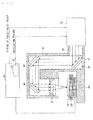
- FIG. 8 illustrates an optical micrograph in which the opening was formed on the silica glass substrate as the workpiece using the laser processing apparatus as described above
- FIG. 9 and FIG. 10 illustrate an omni-focus composite image and an SEM (Scanning Electron Microscope) image thereof, respectively.
- the omni-focus composite image illustrated in FIG. 9 illustrates a three-dimensional display image of an omni-focus composite image obtained by an optical microscope.
- the conditions of pulsed laser light in emission upon processing of a silica glass substrate as a workpiece included an emission energy density of 2 J/cm 2 ⁇ pulse, the number of times of emission of 800 shots, and a repetition frequency of 100 kHz. As illustrated in FIGs.
- timing of laser oscillation in each of the laser oscillators was controlled to control timing of emission of each of the first pulsed laser light and the second pulsed laser light.
- the first pulsed laser light and the second pulsed laser light each involved a wavelength of 10.6 ⁇ m, a pulse width of 10 ns, a repetition frequency of 10 kHz, and an emission energy density of 2 J/cm 2 ⁇ pulse.
- FIG. 11 illustrates a relationship of the interval between the pulses in the respective pieces of pulsed laser light versus a processing depth of the opening where the number of times of emission was 800 shots. As illustrated in FIG. 11 , the processing depth became deep and the processing was promoted at the interval between the pulses of the respective pieces of pulsed laser light of 10 ⁇ s or less. Note that the interval between the pulses of the respective pieces of pulsed laser light here is intended to refer to a minimum pulse interval between a pulse of the pulsed laser light and a pulse of the pulsed laser light.
- Such a short interval between the pulses caused the second pulsed laser light to be emitted while a temperature of the silica glass substrate was increased by emission of the first pulsed laser light and before heat was diffused in a region irradiated with the first pulsed laser light.
- the emission of the second pulsed laser light was performed in a state in which the light absorption coefficient was high as described above, light absorption of the second pulsed laser light was increased and thereby the processing was promoted.
- the first pulsed laser light and the second pulsed laser light each involved the emission energy density of 2 J/cm 2 ⁇ pulse.
- the emission energy density of each of the first pulsed laser light and the second pulsed laser light may be varied depending on a material, etc., that forms the workpiece 70.
- the wavelengths of the respective first pulsed laser light and second pulsed laser light were each 10.6 ⁇ m. However, they may involve different wavelengths depending on a material, etc., that forms the workpiece.
- the wavelength of the first pulsed laser light may be 9.4 ⁇ m and the wavelength of the second pulsed laser light may be 10.6 ⁇ m, for example.
- performing the emission of the pulsed laser light with two or more pulses where the interval between the pulses is 10 ⁇ s or less may increase a processing speed even under a situation where a repetition frequency is low. Also, performing the emission of the pulsed laser light with two or more pulses where the interval between the pulses is 10 ⁇ s or less as described above may reduce thermal strain occurring inside the silica glass substrate as the workpiece 70. This may allow for low-damage processing especially when the workpiece 70 is made of a material difficult to process, such as a hard glass.
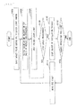
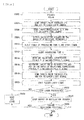
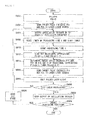
- FIG. 12 A description is given based on FIG. 12 of a laser processing method that uses the laser processing apparatus of the disclosure.
- the controller 60 may send the target pulse energy Pt to the laser light source 10.
- the laser light source 10 may be a short-pulse CO 2 laser light source.
- the laser light source 10 may output the pulsed laser light whose pulse width is 30 ns, and may be capable of varying a wavelength in a range from 9 ⁇ m to 11 ⁇ m.
- Step 104 the controller 60 may output the oscillation trigger, based on the repetition frequency f set in the pulse oscillator 61.
- Step 106 the pulsed laser light may be outputted from the laser light source 10, based on the oscillation trigger.
- the thus-outputted pulsed laser light may be condensed, following which the silica glass substrate as the workpiece 70 may be irradiated with the condensed pulsed laser light.
- Step 108 the controller 60 may determine whether or not to stop the processing performed by the laser processing apparatus. More specifically, a determination may be made as to whether or not it exceeds predetermined processing time or the predetermined number of pulses is emitted to determine whether or not to stop the processing performed by the laser processing apparatus. When it exceeds the predetermined processing time or when the predetermined number of pulses is emitted, the controller 60 may make a determination to stop the processing performed by the laser processing apparatus, and make a transition to Step 110. On the other hand, when it does not exceed the predetermined processing time or when the predetermined number of pulses is not emitted, the controller 60 may make a determination to continue the processing performed by the laser processing apparatus, and make a transition to Step 106.
- Step 110 the controller 60 may stop the output of the oscillation trigger signal. More specifically, because the determination as to the stopping of the processing performed by the laser processing apparatus has been made in the Step 108, the controller 60 may stop the output of the oscillation trigger signal. Thereby, the outputting of the laser light from the laser light source 10 may be stopped as well.
- Step 112 the controller 60 may determine whether or not to change a processing position of the silica glass substrate as the workpiece 70.
- a transition may be made to Step 114 when a determination is made in the controller 60 to change the processing position of the silica glass substrate as the workpiece 70.
- the processing performed by the laser processing apparatus may be ended when a determination is made in the controller 60 not to change the processing position of the silica glass substrate as the workpiece 70.
- Step 114 the controller 60 may move the XYZ stage 50 to move the processing position of the silica glass substrate as the workpiece 70, i.e., to move a position to be irradiated with the pulsed laser light of the silica glass substrate as the workpiece 70.
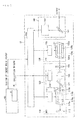
- the laser light source 10 may be a short-pulse CO 2 laser light source. A description is given based on FIG. 13 of the short-pulse CO 2 laser light source.
- the short-pulse CO 2 laser light source that serves as the laser light source 10 may include an MO (master oscillator) 110, a PA (power amplifier) 130, a monitor module 140, and a laser controller 150.
- MO master oscillator
- PA power amplifier
- monitor module 140 monitor module
- laser controller 150 a laser controller
- the MO 110 may include an MO chamber 111, a highly-reflective mirror 112, an MO power supply 113, a Q switch 120, and an output coupling mirror 114.
- an optical resonator may be configured by the highly-reflective mirror 112 and the output coupling mirror 114, and the chamber 111 and the Q switch 120 may be provided in an optical path inside the optical resonator.
- the MO chamber 111 may include a rear window 115a and a front window 115b which may be provided in the optical path of the optical resonator, and a pair of electrodes 116a and 116b which may be provided inside the MO chamber 111.
- the rear window 115a and the front window 115b each may be made of ZnSe.
- the inside of the MO chamber 111 may be filled with laser gas containing CO 2 gas.
- the MO power supply 113 may be an RF (radio frequency) power supply, and may be so connected to the pair of electrodes 116a and 116b as to apply a potential to the pair of electrodes 116a and 116b.
- the highly-reflective mirror 112 may be coated with a reflective film that may reflect the light at the wavelength of 10.6 ⁇ m at high reflectivity.
- the output coupling mirror 114 may include a ZnSe substrate coated with a partially reflective film that may allow part of the light at the wavelength of 10.6 ⁇ m to be transmitted therethrough and allow part thereof to be reflected therefrom.
- the Q switch 120 may include a polarizer 121, an EO Pockels cell 122, and an EO power supply 123.
- the EO Pockels cell 122 may be controlled by a voltage applied by the EO power supply 123.
- the PA 130 may include a PA chamber 131 and a PA power supply 133, and may be disposed in an optical path of laser light outputted from the MO 110.
- the PA chamber 131 may include an entrance window 135a and an exit window 135b, and a pair of electrodes 136a and 136b which may be provided inside the PA chamber 131.
- the entrance window 135a and the exit window 135b each may be made of ZnSe or diamond.
- the inside of the PA chamber 131 may be filled with laser gas containing CO 2 gas.
- the PA power supply 133 may be an RF power supply, and may be so connected to the pair of electrodes 136a and 136b as to apply a potential to the pair of electrodes 136a and 136b.
- the monitor module 140 may include a beam splitter 141 and an energy sensor 142.
- the laser controller 150 may receive the target pulse energy from the controller 61.
- the laser controller 150 may apply, by the MO power supply 113, the potential between the pair of electrodes 116a and 116b of the MO chamber 111 to cause RF discharge to be performed, and thereby the laser gas may be excited.
- the laser controller 150 may apply, by the PA power supply 133, the potential between the pair of electrodes 136a and 136b of the PA chamber 133 to cause RF discharge to be performed, and thereby the laser gas may be excited.
- the laser controller 150 may send a signal to the Q switch 120 of the MO 110 in synchronization with the oscillation trigger derived from the pulse oscillator 61 in the controller 60.
- amplification of 10.6 ⁇ m (line 10P (20)) may be performed by the optical resonator configured by the highly-reflective mirror 112 and the output coupling mirror 114, and thereby the laser oscillation may be performed.
- the pulsed laser light with the pulse width of 30 ns or less and the wavelength of about 10.6 ⁇ m may be outputted by the Q switch 120.
- the pulsed laser light outputted from the PA 130 may be partially branched by the beam splitter 141.
- a pulse energy of the thus-partially-branched pulsed laser light may be measured by the energy sensor 142 of the monitor module 140.
- a signal on a value of the pulse energy thus-measured by the energy sensor 142 of the monitor module 140 may be sent to the laser controller 150.
- the laser controller 150 may perform a feedback control of an excitation intensity through the MO power supply 113 and the PA power supply 130, based on the pulse energy measured by the energy sensor 142.
- the highly-reflective mirror 112 configuring the optical resonator may be formed with the reflective film that reflects the light at the wavelength of 10.6 ⁇ m
- the output coupling mirror 114 configuring the optical resonator may be formed with the partially reflective film that partially reflects the light at the wavelength of 10.6 ⁇ m.
- the inside of the MO chamber 111 may be filled with a gain medium containing the CO 2 laser gas. Synchronizing the Q switch 120 in the MO 110 with the oscillation trigger signal may output the pulsed laser light that involves the wavelength of 10.6 ⁇ m and the pulse width of 30 ns or less.
- MOPA scheme in which the number of PAs is one. Further, however, a plurality of PAs may be disposed in the optical path of the pulsed laser light outputted from the MO. This may further increase energy of the pulsed laser light.
- a chamber for example, a triaxial orthogonal chamber or a slab chamber
- the pairs of electrodes are disposed in the respective MO chamber and PA chamber.
- a high-speed axial chamber may be employed in which a pair of electrodes or a high-frequency coil is disposed outside of each of the MO chamber and the PA chamber.
- the laser light source 10 includes only the MO and includes no PA 130 when a pulse energy of the laser light outputted from the laser light source 10 is allowed to be small.
- a wavelength at which reflectivity of the highly-reflective mirror 112 in the MO 110 reaches a peak and a wavelength at which reflectivity of the film 114 of the output coupling mirror in the MO 110 reaches a peak each may be 9.3 ⁇ m, 9.6 ⁇ m, or 10.2 ⁇ m, for example.
- the wavelength of the outputted laser light may be 9.3 ⁇ m, 9.6 ⁇ m, or 10.2 ⁇ m.
- the highly-reflective mirror 112 may be coated with a film that may allow for high reflection with respect to all of the wavelengths of 9.3 ⁇ m, 9.6 ⁇ m, and 10.2 ⁇ m
- the film 114 of the output coupling mirror may be coated with a film that may allow for partial reflection with respect to the wavelengths of 9.3 ⁇ m, 9.6 ⁇ m, and 10.2 ⁇ m.
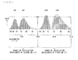
- FIG. 14 illustrates a relationship of amplification lines of a CO 2 laser medium in the short-pulse CO 2 laser light source versus a gain.
- a plurality of amplification lines exist in the CO 2 laser medium in a wavelength range from 9.2 ⁇ m to 10.9 ⁇ m.
- An oscillation wavelength of the short-pulse CO 2 laser light source may be determined by wavelength selectivity of a resonator and the amplification lines.
- the laser light source may be a light source that makes it possible to output laser light of a desired wavelength from a laser light source, with use of a mirror, in an optical resonator, that allows light of the desired wavelength to be reflected. More specifically, varying a wavelength at which reflectivity of the mirror in the optical resonator becomes the maximum may cause a wavelength of laser light outputted from the laser light source to be, for example, 9.27 ⁇ m, 9.59 ⁇ m, 10.24 ⁇ m, or 10.59 ⁇ m, as illustrated in FIG. 15 .
- laser oscillation may be so performed as to be concentrated on a line largest in gain.
- Such a selection of the wavelength derived from the laser light source may be performed with use of a wavelength selective element.
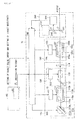
- the short-pulse CO 2 laser light source including the wavelength selective element, illustrated in FIG. 16 may be provided with a wavelength selective element 212 in place of the highly-reflective mirror 112 in the short-pulse CO 2 laser light source illustrated in FIG. 13 .
- the wavelength selective element 212 may have a configuration in which a grating 212a is provided on a rotary stage 212b.
- the rotary stage 212b may be rotated to vary an angle of incidence of light incident on the grating 212a and to increase reflectivity of a desired wavelength.
- the grating 212a may take a Littrow arrangement in which the angle of incidence and an angle of diffraction become the same.
- the monitor module 240 may include a first beam splitter 241, a second beam splitter 242, the energy sensor 142, and a wavelength sensor 244.
- the wavelength sensor 244 may be a spectrometer including a grating or a spectrometer including an etalon.
- contents other than those described above may be similar to those of the short-pulse CO 2 laser light source illustrated in FIG. 13 .
- the laser controller 150 may receive a target wavelength and a target pulse energy from the controller 60.
- the laser controller 150 may send signals on RF discharge corresponding to the target pulse energy to the MO power supply 113 and the PA power supply 133.
- the laser controller 150 may so control the wavelength selective element 212 of the MO 110 as to allow light of the target wavelength to be selected.
- the laser controller 150 may send signals to the MO power supply 113, the PA power supply 133, and the Q switch 122 in the MO 110, in synchronization with the oscillation trigger derived from the pulse oscillator 61 in the controller 60.
- the pulsed laser light to be outputted from the MO 110 may be derived from the laser oscillation based on the line highest in gain among a wavelength spectrum range selected by the grating 212a.
- the pulsed laser light outputted from the MO 110 may be amplified by the PA 130.
- the first beam splitter 241 of the monitor module 240 may allow part of light having entered the first beam splitter 241 to be reflected therefrom and allow the remaining part of the light to be transmitted therethrough.
- the light transmitted through the first beam splitter 241 may enter a laser processing machine.
- the light reflected by the first beam splitter 241 may be branched by the second beam splitter 242 into light to be transmitted through the second beam splitter 242 and light to be reflected from the second beam splitter 242.
- the light transmitted through the second beam splitter 242 may enter the energy sensor 142, and the light reflected from the second beam splitter 242 may enter the wavelength sensor 244.
- the energy sensor 142 and the wavelength sensor 244 may measure the pulse energy and the wavelength of the thus-outputted pulsed laser light, and signals obtained by the measurement may be sent to the laser controller 150.
- the laser controller 150 may rotate, based on the wavelength measured by the wavelength sensor 244, the rotary stage 212b of the wavelength selective element 212 to control the wavelength to be selected by the grating 212a. Also, the laser controller 150 may control, by the MO power supply 113 and the PA power supply 133, a duty of each of voltages applied to the pair of electrodes 116a and 116b and the pair of electrodes 136a and 136b, or a duty of time of each RF discharge thereof, based on the pulse energy measured by the energy sensor 142. A feedback control of the pulse energy may be thereby performed by the laser controller 150.
- the grating 212a may be used as the wavelength selective element 212 to vary the angle of incidence of light incident on the grating 212a. This may vary the oscillation wavelength in a wavelength range from 9 ⁇ m to 11 ⁇ m as illustrated in FIG. 17 .
- a mirror and a grating may be used that take an arrangement that allows for an oblique incidence.
- An etalon unillustrated in FIG. 16 may be arranged in the optical resonator.
- Such an etalon may satisfy the following expression (1) where, for example, the wavelength of the laser light may be assumed as 9.95 ⁇ m and a refractive index n of nitrogen gas may be assumed as 1.000.
- the etalon may include a configuration in which surfaces of respective ZnSe substrates are each coated with a partially reflective film (reflectivity in a range from 70% to 90%) and are bonded together with a spacer interposed in between.
- the short-pulse CO 2 laser light source including the quantum cascade laser, illustrated in FIG. 18 may use an MO 250 that includes a quantum cascade laser (QCL) 251 in place of the MO in the short-pulse CO 2 laser light source illustrated in FIG. 13 .
- the quantum cascade laser 251 may be a laser that includes a semiconductor and a grating, and oscillates at a single longitudinal mode. Also, the quantum cascade laser 251 may include an actuator that varies a wavelength selected by the grating and a power supply that causes a pulse current to flow to the semiconductor.
- the quantum cascade laser 251 may be made of a compound semiconductor material such as InP and GaAs.
- a plurality of PAs may be disposed in an optical path of the laser light outputted from the MO 250.
- a configuration may be employed in which a first PA 261, a second PA 262, and a third PA 263 are disposed in order in the optical path of the laser light outputted from the MO 250 in a case illustrated in FIG. 18 .
- the first PA 261 may be a regenerative amplifier.
- the monitor module 240 may include the first beam splitter 241, the second beam splitter 242, the energy sensor 142, and the wavelength sensor 244.
- the wavelength sensor 244 may be the spectrometer including the grating or the spectrometer including the etalon.
- contents other than those described above may be similar to those of the short-pulse CO 2 laser light source illustrated in FIG. 13 .
- the laser controller 150 may receive the target wavelength and the target pulse energy from the controller 60.
- the laser controller 150 may send signals on RF, to be used to perform excitation corresponding to the target pulse energy, to the power supplies of the respective first PA 261, second PA 262, and third PA 263.
- the laser controller 150 may so control an unillustrated wavelength selective element in the quantum cascade laser 251 as to allow light of the target wavelength to be selected.
- the laser controller 150 may input a signal into an unillustrated pulse current power supply in the quantum cascade laser 251, in synchronization with the oscillation trigger derived from the pulse oscillator 61 in the controller 60.
- the pulsed laser light outputted from the quantum cascade laser 251 may be derived from a laser that performs laser oscillation based on the wavelength selected by the unillustrated wavelength selective element in the quantum cascade laser 251.
- the pulsed laser light whose pulse width is 30 ns and wavelength is based on any amplification line at a wavelength (ranging from 8 ⁇ m to 11 ⁇ m), may be outputted from the quantum cascade laser 251 as the laser.
- the pulsed laser light thus outputted from the quantum cascade laser 251 may be amplified by the plurality of PAs, i.e., the first PA 261, the second PA 262, and the third PA 263, as the amplifiers in which amplification is performed based on amplification lines substantially coincident with the amplification lines of the CO 2 laser medium.
- Part of the laser light thus amplified and thus outputted from the third PA 263 may be reflected by the first beam splitter 241 of the monitor module 240. Further, part of the laser light reflected by the first beam splitter 241 may be branched by the second beam splitter 242 into light to be transmitted through the second beam splitter 242 and light to be reflected from the second beam splitter 242. The light transmitted through the second beam splitter 242 may enter the energy sensor 142, and the light reflected from the second beam splitter 242 may enter the wavelength sensor 244.
- the laser controller 150 may control, based on the wavelength of the pulsed laser light measured by the wavelength sensor 244, the oscillation wavelength of the quantum cascade laser 251 to meet the target wavelength.
- the oscillation wavelength of the quantum cascade laser 251 may be controlled in the wavelength range from 9 ⁇ m to 11 ⁇ m to control the wavelength of the pulsed laser light outputted from the laser light source.
- the first short-pulse CO 2 laser light source that outputs the pieces of laser light of respective two wavelengths may include an MO section 310 that includes a first MO 311, a second MO 312, and a third beam splitter 313.
- the first MO 311 and the second MO 312 may be oscillators that may oscillate at respective wavelengths different from each other.
- the first MO 311 and the second MO 312 may each be a quantum cascade laser that includes an unillustrated grating.
- the third beam splitter 313 may function as a half mirror (50% for transmission and 50% for reflection) with respect to wavelengths derived from the respective first MO 311 and second MO 312.
- the third beam splitter 313 may be disposed in an optical path of the pulsed laser light outputted from the first MO 311, and may be disposed in an optical path of the pulsed laser light outputted from the second MO 312.
- the third beam splitter 313 may be so provided as to allow the center of an optical path axis of the pulsed laser light, outputted from the first MO 311 and transmitted through the third beam splitter 313, to be brought into coincidence with the center of an optical path axis of the pulsed laser light outputted from the second MO 312 and reflected from the third beam splitter 313.
- a plurality of PAs may be disposed in an optical path of the laser light outputted from the MO section 310.
- a configuration may be employed in which the first PA 261, the second PA 262, and the third PA 263 are disposed in order in the optical path of the laser light outputted from the MO section 310 in a case illustrated in FIG. 19 .
- the monitor module 240 may include the first beam splitter 241, the second beam splitter 242, the energy sensor 142, and the wavelength sensor 244.
- the wavelength sensor 244 may be the spectrometer including the grating or the spectrometer including the etalon.
- contents other than those described above may be similar to those of the short-pulse CO 2 laser light source illustrated in FIG. 13 .
- the laser controller 150 may receive two target wavelengths ( ⁇ 1t and ⁇ 2t) and two target pulse energies (P1t and P2t) from the controller 60.
- the laser controller 150 may send signals on current values to the respective first MO 311 and second MO 312, and send signals on RF, to be used to perform excitation corresponding to the target pulse energies, to the power supplies of the respective first PA 261, second PA 262, and third PA 263.
- the laser controller 150 may so control unillustrated wavelength selective elements in the respective first MO 311 and second MO 312 as to allow their respective pieces of light of the target wavelengths to be selected, in a case where the first MO 311 and the second MO 312 are each the quantum cascade laser.
- the laser controller 150 may input signals into respective unillustrated pulse current power supplies of the quantum cascade lasers of the respective first MO 311 and second MO 312 together, in synchronization with the oscillation trigger derived from the pulse oscillator 61 in the controller 60.
- the first MO 311 and the second MO 312 may be MOs that oscillate at the respective wavelengths selected by their respective wavelength selective elements provided therein.
- the pieces of pulsed laser light thus outputted from the respective first MO 311 and second MO 312 may be amplified by the plurality of PAs, i.e., the first PA 261, the second PA 262, and the third PA 263, as the amplifiers in which amplification is performed based on each of two wavelengths each of which is substantially coincident with the amplification lines of the CO 2 laser medium.
- each pulsed laser light may be reflected by the first beam splitter 241 of the monitor module 240. Further, part of each laser light reflected by the first beam splitter 241 may be branched by the second beam splitter 242 into light to be transmitted through the second beam splitter 242 and light to be reflected from the second beam splitter 242. Each light transmitted through the second beam splitter 242 may enter the energy sensor 142, and each light reflected from the second beam splitter 242 may enter the wavelength sensor 244.
- the laser controller 150 may control, based on the wavelengths of the respective pieces of pulsed laser light measured by the wavelength sensor 244, the oscillation wavelengths of the respective first MO 311 and second MO 312 to meet the respective two target wavelengths.
- the wavelength sensor 244 may measure a relationship between a wavelength of the laser light and a light intensity
- the wavelength sensor 244 may measure the respective light intensities of the pieces of laser light of the respective two different wavelengths. Thereby, respective intensity peaks (S1 and S2) of the pieces of laser light of the respective two different wavelengths may be obtained by the wavelength sensor 244.
- the energy sensor 142 may measure sum Psum of the respective pulse energies of the pieces of pulsed laser light of the respective two different wavelengths.
- the pulse energies P1 and P2 for the respective measured wavelengths ( ⁇ 1 and ⁇ 2) may be determined based on the following expressions (2) and (3).
- P ⁇ 1 Psum ⁇ S ⁇ 1 / S ⁇ 1 + S ⁇ 2
- P ⁇ 2 Psum ⁇ S ⁇ 2 / S ⁇ 1 + S ⁇ 2
- the laser controller 150 may so perform a control as to allow the target pulse energies P1t and P2t for the respective wavelengths to be obtained, based on the determined pulse energies P1 and P2 for the respective measured wavelengths ( ⁇ 1 and ⁇ 2). More specifically, the laser controller 150 may perform a feedback control of an excitation intensity on the first MO 311, the second MO 312, the first PA 261, the second PA 262, and the third PA 263, based on the pulse energies P1 and P2.
- the laser light source may control the oscillation wavelength of the first MO 311 in a wavelength range from 9 ⁇ m to 10 ⁇ m and control the oscillation wavelength of the second MO 312 in a wavelength range from 10 ⁇ m to 11 ⁇ m to control the pieces of pulsed laser light of the respective two wavelengths outputted from the laser light source.
- the respective optical path axes in the optical paths of the respective pieces of pulsed laser light outputted from the respective first MO 311 and second MO 312 may be brought into coincidence with each other by the third beam splitter 313 to perform the amplification by the same first PA 261, second PA 262, and third PA 263.
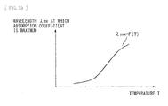
- a wavelength at which the absorption coefficient is maximum may be in a range from 9 ⁇ m to 10 ⁇ m at a temperature in the initial stage of processing, and may be in a range from 10 ⁇ m to 11 ⁇ m upon a temperature increased by the processing.
- irradiation of the workpiece that includes the glass with the respective pieces of pulsed laser light of the two different wavelength in the respective wavelength ranges from 9 ⁇ m to 10 ⁇ m and from 10 ⁇ m to 11 ⁇ m increases absorption of the pulsed laser light in the workpiece. Hence, this may make it possible to shorten processing time, etc.
- the number of MOs included in the MO section 310 is not limited to two, and may be three or more. Also, these MOs may be MOs whose respective oscillation wavelengths and pulse energies are independently controlled.
- the MOs included in the MO section 310 each may include, besides the quantum cascade laser, a chamber filled with the CO 2 laser medium as illustrated in FIG. 13 .
- the second short-pulse CO 2 laser light source that outputs the pieces of laser light of respective two wavelengths may include the first MO 311 and the second MO 312.
- the first MO 311 may output pulsed laser light at a wavelength of 10.6 ⁇ m
- the second MO 312 may output pulsed laser light at a wavelength of 9.3 ⁇ m.
- a first PA 321 a, a second PA 322a, and a third PA 323a may be provided in an optical path of the pulsed laser light outputted from the first MO 311, and a first PA 321 b, a second PA 322b, and a third PA 323b may be provided in an optical path of the pulsed laser light outputted from the second MO 312.
- the side on which the pulsed laser light is outputted of the third PA 323a may be provided with a dichroic mirror 331.
- the dichroic mirror 331 may include a diamond substrate coated with a film that may allow the light at the wavelength of 10.6 ⁇ m to be transmitted therethrough at high transmittance and allow the light at the wavelength of 9.3 ⁇ m to be reflected therefrom at high reflectivity.
- the side on which the pulsed laser light is outputted of the third PA 323b may be provided with a highly-reflective mirror 332 that may reflect the light at the wavelength of 9.3 ⁇ m at high reflectivity.
- the highly-reflective mirror 332 and the dichroic mirror 331 may be so disposed as to allow the center of an optical path axis of the pulsed laser light outputted from the third PA 323a to be brought into coincidence with the center of an optical path axis of the pulsed laser light outputted from the third PA 323b.
- the monitor module 240 may include the first beam splitter 241, the second beam splitter 242, the energy sensor 142, and the wavelength sensor 244.
- the wavelength sensor 244 may be the spectrometer including the grating or the spectrometer including the etalon.
- contents other than those described above may be similar to those of the short-pulse CO 2 laser light source illustrated in FIG. 13 .
- the laser controller 150 may receive the target pulse energies (P1t and P2t) for the respective wavelengths ⁇ 1 and ⁇ 2 from the controller 60.
- the laser controller 150 may receive the oscillation trigger sent from the controller 60.
- the first MO 311 may output the pulsed laser light at the wavelength of 10.6 ⁇ m
- the second MO 312 may output the pulsed laser light at the wavelength of 9.3 ⁇ m.
- the pulsed laser light outputted from the first MO 311 may be amplified by the first PA 321 a, the second PA 322a, and the third PA 323a. Also, the pulsed laser light outputted from the second MO 312 may be amplified by the first PA 321 b, the second PA 322b, and the third PA 323b.
- the laser light outputted from the third PA 323b may be reflected by the highly-reflective mirror 332 to be incident on the dichroic mirror 331, and the thus-incident laser light may be reflected by the dichroic mirror 331.
- the laser light outputted from the third PA 323a may be transmitted through the dichroic mirror 331.
- An optical path axis of the pulsed laser light at the wavelength of 10.6 ⁇ m transmitted through the dichroic mirror 331 may be the same as an optical path axis of the pulsed laser light at the wavelength of 9.3 ⁇ m reflected from the dichroic mirror 332.
- the pulsed laser light at the wavelength of 10.6 ⁇ m transmitted through the dichroic mirror 331 and the pulsed laser light at the wavelength of 9.3 ⁇ m reflected from the dichroic mirror 331 may enter the monitor module 240.
- part of the pulsed laser light at the wavelength of 10.6 ⁇ m transmitted through the dichroic mirror 331 and part of the pulsed laser light at the wavelength of 9.3 ⁇ m reflected from the dichroic mirror 331 may be reflected by the first beam splitter 241.
- the respective parts of the pieces of pulsed laser light reflected by the first beam splitter 241 each may be branched by the second beam splitter 242 into light to be transmitted through the second beam splitter 242 and light to be reflected from the second beam splitter 242.
- Each light transmitted through the second beam splitter 242 may enter the energy sensor 142, and each light reflected from the second beam splitter 242 may enter the wavelength sensor 244.
- the laser controller 150 may control, based on the wavelengths of the respective pieces of pulsed laser light measured by the wavelength sensor 244, the oscillation wavelengths of the respective first MO 311 and second MO 312 to meet the respective two target wavelengths.
- the wavelength sensor 244 may measure a relationship between a wavelength of the laser light and a light intensity
- the wavelength sensor 244 may measure the respective light intensities of the pieces of laser light of the respective two different wavelengths. Thereby, the respective intensity peaks (S1 and S2) of the pieces of laser light of the respective two different wavelengths may be obtained by the wavelength sensor 244.
- the energy sensor 142 may measure the sum Psum of the respective pulse energies of the pieces of pulsed laser light of the respective two different wavelengths.
- the pulse energies P1 and P2 for the respective wavelengths ( ⁇ 1 and ⁇ 2) measured by the energy sensor 142 may be determined based on the following expressions (2) and (3).
- P ⁇ 1 Psum ⁇ S ⁇ 1 / S ⁇ 1 + S ⁇ 2
- P ⁇ 2 Psum ⁇ S ⁇ 2 / S ⁇ 1 + S ⁇ 2
- the laser controller 150 may so perform a control as to allow the target pulse energies P1t and P2t for the respective wavelengths to be obtained, based on the determined pulse energies P1 and P2 for the respective measured wavelengths ( ⁇ 1 and ⁇ 2). More specifically, the laser controller 150 may perform a feedback control of an excitation intensity on the first MO 311, the first PA 321 a, the second PA 322a, and the third PA 323a, based on the pulse energy P1. Also, the laser controller 150 may perform a feedback control of an excitation intensity on the second MO 312, the first PA 321 a, the second PA 322a, and the third PA 323a, based on the pulse energy P2.
- the dichroic mirror 331 may cause the pieces of pulsed laser light of the respective two different wavelengths (9.3 ⁇ m and 10.6 ⁇ m) outputted from the laser light source to be outputted in the same optical path axis.
- the laser controller 150 may so perform a control as to allow the target pulse energies for the respective wavelengths ⁇ 1 and ⁇ 2 to meet the respective target energies P1t and P2t.
- the inside of an MO chamber of each of the first MO 311 and the second MO 312 may be filled with a CO 2 gain medium as with the MO illustrated in FIG. 13 .
- an optical resonator length or a wavelength corresponding to a peak of a reflectivity of the highly-reflective mirror, etc. may be varied therebetween to obtain different wavelengths (for example, 9.3 ⁇ m and 10.6 ⁇ m).
- the short-pulse CO 2 laser light source that outputs the laser light of two wavelengths with use of an etalon may include, inside an optical resonator in the MO 350, a wavelength selective element 360 including the etalon.
- the wavelength selective element 360 including the etalon may include two ZnSe substrates 361.
- One surface of each of the two ZnSe substrates 361 may be coated with a partially reflective film 361 a, and the surfaces coated with the respective partially reflective films 361 a may be opposed to each other with a spacer 362 in between to form the etalon.
- the thus-formed etalon may be provided on a rotary stage 363.
- a reflectivity of each of the partially reflective films 361 a may be in a range from 70% to 90%.
- the wavelength selective element 360 including the etalon may satisfy the following expression (4) where, for example, the wavelength of the laser light may be assumed as 9.95 ⁇ m and a refractive index n of nitrogen gas may be assumed as 1.000.
- contents other than those described above may be similar to those of the short-pulse CO 2 laser light source including the wavelength selective element, illustrated in FIG. 16 .
- an angle of incidence of the etalon may be placed to a predetermined angle to set peak wavelengths of transmittance of the etalon to 9.3 ⁇ m and 10.6 ⁇ m as illustrated in FIG. 23 .
- the MO 350 may perform the oscillation based on two amplification lines that are near the peak wavelengths of the transmittance of the etalon and high in gain.
- the pulsed laser light derived from the oscillation based on the two amplification lines of the MO 350 may be amplified by the PA 130.
- the pulsed laser light amplified by the PA 130 may enter the monitor module 240. Part of the laser light having entered the monitor module 240 may be reflected by the first beam splitter 241 in the monitor module 240. Further, part of the laser light reflected by the first beam splitter 241 may be branched by the second beam splitter 242 into light to be transmitted through the second beam splitter 242 and light to be reflected from the second beam splitter 242. The light transmitted through the second beam splitter 242 may enter the energy sensor 142, and the light reflected from the second beam splitter 242 may enter the wavelength sensor 244. In the monitor module 240, the peak wavelengths and the pulse energies of the laser light of the two different wavelengths may be measured respectively by the wavelength sensor 244 and the energy sensor 142. The laser controller 150 may so perform a feedback control as to allow the peak wavelengths and the pulse energies of the laser light of the two different wavelengths to meet the target wavelengths and the target pulse energies.
- the laser light source may output two pieces of pulsed laser light at the different wavelengths by so designing the wavelength selective element 360 including the etalon as to allow at least two peaks of the transmittance to be within a distribution of the amplification lines of the CO 2 laser medium. Also, the laser light source may be capable of varying the oscillation wavelength within the range of the amplification lines of the CO 2 laser gain medium while making a difference between the two oscillation wavelengths (FSR) to be substantially constant, by controlling the angle of incidence of the etalon in the wavelength selective element 360 including the etalon.
- FSR two oscillation wavelengths
- the laser light source 10 may be a wavelength-variable solid-state laser light source. A description is given based on FIG. 24 of the wavelength-variable solid-state laser light source.
- the laser unit 10 may include an MO 410, a PA 420, an OPO (optical parametric oscillator) 430, the monitor module 240, an excitation pulsed laser light source 440, and the laser controller 150. Also, a third beam splitter 451, a fourth beam splitter 452, a fifth beam splitter 453, and a highly-reflective mirror 454 may be provided in an optical path of the pulsed laser light outputted from the excitation pulsed laser light source 440.
- OPO optical parametric oscillator
- the excitation pulsed laser light source 440 may be a Tm-based pulsed laser unit (wavelength of 2 ⁇ m) that outputs the pulsed laser light at hundreds of nanoseconds and at a wavelength of 2 ⁇ m.
- the MO 410 may include a highly-reflective mirror 411, a wavelength selective element 412, a Cr:ZnSe crystal 413, a Q switch 414, and an output coupling mirror 415.
- An optical resonator may be configured by the highly-reflective mirror 411 and the output coupling mirror 415, and the wavelength selective element 412, the Cr:ZnSe crystal 413, and the Q switch 414 may be provided in an optical path inside the optical resonator.
- the wavelength selective element 412 may be a wavelength selective element such as an etalon, a grating, and a prism.
- the Q switch 414 may be a combination, unillustrated in FIG. 24 , of a polarizer and an EO Pockels cell.
- the PA 420 may include a plurality of Cr:ZnSe crystals, e.g., a first Cr:ZnSe crystal 421, a second Cr:ZnSe crystal 422, and a third Cr:ZnSe crystal 423, that may be disposed in the optical path of the pulsed laser light outputted from the MO 410.
- a first Cr:ZnSe crystal 421, a second Cr:ZnSe crystal 422, and a third Cr:ZnSe crystal 423 that may be disposed in the optical path of the pulsed laser light outputted from the MO 410.
- the OPO 430 may include a highly-reflective mirror 431, a ZnGeP 2 crystal 432, and an output coupling mirror 433.
- the monitor module 240 may include the first beam splitter 241, the second beam splitter 242, the energy sensor 142, and the wavelength sensor 244.
- the wavelength sensor 244 may be, unillustrated in FIG. 24 , the spectrometer including the grating or the spectrometer including the etalon.
- the laser controller 150 may receive the target wavelength and the target pulse energy from the controller 60.
- the laser controller 150 may send an excitation pulse energy corresponding to the target pulse energy to the excitation pulsed laser light source 440.
- the laser controller 150 may so control the wavelength selective element 412 in the MO 410 as to allow light of the target wavelength to be selected.
- the laser controller 150 may send signals to the excitation pulsed laser light source 440 and the Q switch 414 in the MO 410, in synchronization with the oscillation trigger derived from the pulse oscillator 61 in the controller 60.
- the pulsed laser light outputted from the excitation pulsed laser light source 440 may be reflected by the third beam splitter 451 to enter the Cr:ZnSe crystal 413 in the MO 410.
- the pulsed laser light outputted from the excitation pulsed laser light source 440 may be transmitted through the third beam splitter 451, following which the pulsed laser light transmitted through the third beam splitter 451 may be reflected by the fourth beam splitter 452.
- the pulsed laser light thus reflected by the fourth beam splitter 452 may enter the first Cr:ZnSe crystal 421 in the PA 420.
- the pulsed laser light outputted from the excitation pulsed laser light source 440 may be transmitted through the third beam splitter 451 and the fourth beam splitter 452, following which the pulsed laser light transmitted through the third beam splitter 451 and the fourth beam splitter 452 may be reflected by the fifth beam splitter 453.
- the pulsed laser light thus reflected by the fifth beam splitter 453 may enter the second Cr:ZnSe crystal 422 in the PA 420.
- the pulsed laser light outputted from the excitation pulsed laser light source 440 may be transmitted through the third beam splitter 451, the fourth beam splitter 452, and the fifth beam splitter 453, following which the pulsed laser light transmitted through the third beam splitter 451, the fourth beam splitter 452, and the fifth beam splitter 453 may be reflected by the highly-reflective mirror 454.
- the pulsed laser light thus reflected by the highly-reflective mirror 454 may enter the third Cr:ZnSe crystal 423 in the PA 420.
- the Cr:ZnSe crystal 413 in the MO 410 as well as the first Cr:ZnSe crystal 421, the second Cr:ZnSe crystal 422, and the third Cr:ZnSe crystal 423 in the PA 420 may be excited.
- the light of the wavelength selected by the wavelength selective element 412 may be amplified by the Cr:ZnSe crystal 413 to be subjected to laser oscillation before being outputted through the Q switch 414.
- the pulsed laser light outputted from the MO 410 may be the pulsed laser light (at about 15 ns) of a wavelength in a wavelength range from 2 ⁇ m to 2.7 ⁇ m.
- the PA 420 may amplify the pulsed laser light outputted from the MO 410 by the excited first Cr:ZnSe crystal 421, second Cr:ZnSe crystal 422, and third Cr:ZnSe crystal 423.
- the pulsed laser light amplified by the PA 420 is transmitted through the highly-reflective mirror 431 to enter the ZnGeP 2 crystal 432 in the OPO 430.
- This pulsed laser light may be subjected to optical parametric oscillation by the optical resonator configured by the output coupling mirror 433 and the highly-reflective mirror 431.
- the pulsed laser light having been subjected to the optical parametric oscillation may be outputted from the OPO 430 with the pulse width of about 15 ns, the wavelength in a range from 8 ⁇ m to 10 ⁇ m, and the pulse energy of about 10 mJ.
- the pulsed laser light having been subjected to the optical parametric oscillation may enter the monitor module 240.
- Part of the pulsed laser light having entered the monitor module 240 may be reflected by the first beam splitter 241 in the monitor module 240.
- part of the laser light reflected by the first beam splitter 241 may be branched by the second beam splitter 242 into light to be transmitted through the second beam splitter 242 and light to be reflected from the second beam splitter 242.
- the light transmitted through the second beam splitter 242 may enter the energy sensor 142, and the light reflected from the second beam splitter 242 may enter the wavelength sensor 244.
- the wavelength and the pulse energy of the pulsed laser light outputted from the OPO 430 may be measured by the wavelength sensor 244 and the energy sensor 142, and information on the measurement may be sent to the laser controller 150.
- the laser controller 150 may perform a feedback control of the transmission wavelength on the wavelength selective element 412, based on the wavelength measured by the wavelength sensor 244. Also, the laser controller 150 may perform a feedback control of the pulse energy on the excitation pulsed laser light source 440, based on the pulse energy measured by the energy sensor 142.
- the wavelength-variable solid-state laser light source makes it possible to perform generation of the pulsed laser light even at a shorter wavelength range (from 8 ⁇ m to 10 ⁇ m) than an oscillation wavelength range (from 9 ⁇ m to 11 ⁇ m) of a laser light source containing CO 2 laser gas.
- FIG. 25 A description is given based on FIG. 25 of a laser processing apparatus that includes a heating section used to heat a workpiece.
- the laser processing apparatus including the heating section may be provided with a heating section 510 on the table 51.
- the heating section 510 may be provided with a heater 511 on the table 51 side, and the workpiece 70 may be placed on the heater 511.
- a housing 512 may be so provided as to cover the workpiece 70.
- the housing 512 may be provided with an opening section at a region where the pulsed laser light enters via the laser condensing optical member 44 such as a lens, and the opening section may be provided with a window section 513 which may be made of ZnSe.
- a temperature sensor 514 Inside of the housing 512 may be provided with a temperature sensor 514. There may be provided a heater power supply 521 to be used to heat the heater 511, and a temperature controller 522 that measures a temperature by the temperature sensor 514 to control the heater 511 by the heater power supply 521. Hence, a control may be so performed as to allow the workpiece 70 to be at a predetermined temperature.
- the controller 60 may send the target pulse energy Pt to the laser light source 10.
- the laser light source 10 may be the short-pulse CO 2 laser light source.
- the laser light source 10 may output the pulsed laser light whose pulse width is 30 ns, and may be capable of varying the wavelength in a range from 9 ⁇ m to 11 ⁇ m.
- Step 204 the controller 60 may so set a temperature set in the temperature controller 522 as to be at the target temperature Tt.
- the target temperature Tt may be set at a temperature equal to or greater than 400°C and less than 800°C when the workpiece 70 contains silica glass.
- Step 206 a determination may be made as to whether or not a difference between the temperature measured by the temperature sensor 514 and the target temperature Tt is less than a predetermined temperature difference ⁇ Tr, i.e., a determination may be made as to whether or not ⁇ Tr ⁇
- a transition may be made to Step 208.
- Step 206 may be performed again when it is determined that ⁇ Tr ⁇
- the predetermined temperature difference ⁇ Tr may be in a range from 1°C to 10°C, for example.
- Step 208 the controller 60 may output the oscillation trigger, based on the repetition frequency f set in the pulse oscillator 61.
- the pulsed laser light may be outputted from the laser light source 10, based on the oscillation trigger.
- the thus-outputted pulsed laser light may be condensed, following which the silica glass substrate as the workpiece 70 may be irradiated with the condensed pulsed laser light.
- Step 212 the controller 60 may determine whether or not to stop the processing performed by the laser processing apparatus. More specifically, a determination may be made as to whether or not it exceeds predetermined processing time or the predetermined number of pulses is emitted to determine whether or not to stop the processing performed by the laser processing apparatus. When it exceeds the predetermined processing time or when the predetermined number of pulses is emitted, the controller 60 may make a determination to stop the processing performed by the laser processing apparatus, and make a transition to Step 214. On the other hand, when it does not exceed the predetermined processing time or when the predetermined number of pulses is not emitted, the controller 60 may make a determination to continue the processing performed by the laser processing apparatus, and make a transition to Step 208.
- Step 214 the controller 60 may stop the output of the oscillation trigger signal. More specifically, because the determination as to the stopping of the processing performed by the laser processing apparatus has been made in the Step 212, the controller 60 may stop the output of the oscillation trigger signal. Thereby, the outputting of the laser light from the laser light source 10 may be stopped as well.
- Step 216 the controller 60 may determine whether or not to change a processing position of the silica glass substrate as the workpiece 70.
- a transition may be made to Step 218 when a determination is made in the controller 60 to change the processing position of the silica glass substrate as the workpiece 70.
- the processing performed by the laser processing apparatus may be ended when a determination is made in the controller 60 not to change the processing position of the silica glass substrate as the workpiece 70.
- Step 218 the controller 60 may move the XYZ stage 50 to move the processing position of the silica glass substrate as the workpiece 70, i.e., to move a position to be irradiated with the pulsed laser light of the silica glass substrate as the workpiece 70.
- This laser processing method may make it possible to increase an absorption coefficient of the wavelength of the pulsed laser light at the wavelength of 10.6 ⁇ m when the workpiece 70 is the glass substrate configured of silica glass, by heating the glass substrate with use of the heater 512 to allow the temperature of the glass substrate to be at about 400°C.
- FIG. 27 illustrates a relationship of a repetition frequency versus a depth of a processed hole of an opening formed on the silica glass substrate as the workpiece 70, where temperatures of the silica glass substrate as the workpiece 70 were at a room temperature and at 500°C.
- the conditions of laser processing included a wavelength of pulsed laser light of 10.6 ⁇ m, a pulse width of 10 ns, an emission energy density of 2 J/cm 2 ⁇ pulse, and the number of times of emission of 800 shots. Even with the same repetition frequency, the processing depth of the opening was deeper and thus the processing was promoted in a case where the temperature of the silica glass substrate was 500°C, as compared with a case where the temperature of the silica glass substrate was at an ordinary temperature.
- FIG. 28 illustrates a relationship of a temperature of a silica glass substrate versus a depth of a processed hole of an opening formed on the silica glass substrate as the workpiece 70.
- the conditions of laser processing included a wavelength of pulsed laser light of 10.6 ⁇ m, a repetition frequency of 10 kHz, a pulse width of 10 ns, an emission energy density of 2 J/cm 2 ⁇ pulse, and the number of times of emission of 800 shots.
- the processing depth of the opening was deeper and thus the processing was promoted when the temperature of the silica glass substrate was 400°C or higher.
- the workpiece is a hard glass substrate
- heating with use of a heater or a lamp from the stage side upon performing heating of the hard glass substrate may cause strain resulting from a temperature gradient inside the hard glass substrate, which may lead to breakage of the hard glass substrate upon increase and decrease of the temperature.
- the temperature of the hard glass substrate be increased and decreased without causing the temperature gradient inside the hard glass substrate.
- a method such as heating with use of an oven and heating performed while both surfaces of the hard glass substrate are sandwiched by Si may be preferable to reduce the temperature gradient inside the hard glass substrate, etc.
- FIG. 29 A description is given based on FIG. 29 of a laser processing apparatus that includes a wavelength-variable laser light source.
- the laser processing apparatus including the wavelength-variable laser light source may include, as the laser light source 10, a wavelength-variable laser light source capable of varying a wavelength to be outputted.
- the wavelength-variable laser light source may be variable in wavelength of laser light to be outputted in a range from 9 ⁇ m to 11 ⁇ m.
- Such a wavelength-variable laser light source may be a laser light source such as, for example, any of the laser light sources illustrated in FIGs. 16 , 18 , and 24 .
- the controller 60 may be provided with a memory section 62.
- the controller 60 may send the target pulse energy Pt to the laser light source 10.
- the laser light source 10 may be the short-pulse CO 2 laser light source.
- the laser light source 10 may output pulsed laser light whose pulse width is 30 ns, and may be capable of varying the wavelength in a range from 9 ⁇ m to 11 ⁇ m.
- Step 304 the controller 60 may output the oscillation trigger, based on the repetition frequency f set in the pulse oscillator 61.
- Step 306 the controller 60 may reset a timer of the processing time t and then start the timer.
- Step 308 the controller 60 may measure the processing time t, based on the timer started in the Step 306.
- Step 312 the controller 60 may determine a target wavelength ⁇ mxt at which the absorption coefficient is the maximum, based on the target pulse energy Pt, the processing time t, and the repetition frequency f.
- Step 314 the controller 60 may send the target wavelength ⁇ mxt at which the absorption coefficient is the maximum, determined in the Step 312, to the laser light source 10.
- Step 316 the pulsed laser light may be outputted from the laser light source 10, based on the oscillation trigger.
- the thus-outputted pulsed laser light may be condensed, following which the silica glass substrate as the workpiece 70 may be irradiated with the condensed pulsed laser light.
- Step 318 the controller 60 may determine whether or not to stop the processing performed by the laser processing apparatus. More specifically, a determination may be made as to whether or not it exceeds predetermined processing time or the predetermined number of pulses is emitted to determine whether or not to stop the processing performed by the laser processing apparatus. When it exceeds the predetermined processing time or when the predetermined number of pulses is emitted, the controller 60 may make a determination to stop the processing performed by the laser processing apparatus, and make a transition to Step 320. On the other hand, when it does not exceed the predetermined processing time or when the predetermined number of pulses is not emitted, the controller 60 may make a determination to continue the processing performed by the laser processing apparatus, and make a transition to Step 308.
- Step 320 the controller 60 may stop the output of the oscillation trigger signal. More specifically, because the determination as to the stopping of the processing performed by the laser processing apparatus has been made in the Step 318, the controller 60 may stop the output of the oscillation trigger signal. Thereby, the outputting of the laser light from the laser light source 10 may be stopped as well.
- Step 322 the controller 60 may determine whether or not to change a processing position of the silica glass substrate as the workpiece 70.
- a transition may be made to Step 324 when a determination is made in the controller 60 to change the processing position of the silica glass substrate as the workpiece 70.
- the processing performed by the laser processing apparatus may be ended when a determination is made in the controller 60 not to change the processing position of the silica glass substrate as the workpiece 70.
- Step 324 the controller 60 may move the XYZ stage 50 to move the processing position of the silica glass substrate as the workpiece 70, i.e., to move a position to be irradiated with the pulsed laser light of the silica glass substrate as the workpiece 70.
- the controller 60 may determine the target wavelength ⁇ mxt at which the absorption coefficient is the maximum, based on the relational expression, etc., that may define the relationship among the wavelength ⁇ mx at which the absorption coefficient is the maximum, the processing time t, the repetition frequency f, and the pulse energy P. Controlling the oscillation wavelength of the laser light source 10 to meet the thus-determined target wavelength ⁇ mxt at which the absorption coefficient is the maximum may maximize light to be absorbed by the workpiece 70 such as silica glass.
- Laser Processing Apparatus including Temperature Measuring Section for Workpiece
- FIG. 32 A description is given based on FIG. 32 of a laser processing apparatus that includes a temperature measuring section for workpiece.
- the laser processing apparatus including the temperature measuring section for workpiece may include a temperature measuring section that measures a temperature at a laser processed region on the workpiece 70.
- the temperature measuring section 540 may be a radiation thermometer.
- the radiation thermometer may measure the temperature, based on infrared light, etc., of a wavelength different from the wavelength of the pulsed laser light outputted from the laser unit.
- a detection device used to detect the temperature may be configured of InGaAs.
- the detection device configured of InGaAs may involve a detection wavelength of 1.55 ⁇ m, and a measured temperature range may range from 300°C to 1600°C.
- the wavelength-variable laser light source capable of varying a wavelength to be outputted may be used as the laser light source 10.
- the wavelength-variable laser light source may be variable in wavelength of laser light to be outputted in a range from 9 ⁇ m to 11 ⁇ m.
- Such a wavelength-variable laser light source may be a laser light source such as, for example, any of the laser light sources illustrated in FIGs. 16 , 18 , and 24 .
- the controller 60 may be provided with the memory section 62.
- the relationship between the wavelength ⁇ mx at which the absorption coefficient is the maximum and the temperature T may be determined from data derived from actual measurement, or may be obtained based on literature, etc.
- the controller 60 may send the target pulse energy Pt to the laser light source 10.
- the laser light source 10 may be the short-pulse CO 2 laser light source.
- the laser light source 10 may output pulsed laser light whose pulse width is 30 ns, and may be capable of varying the wavelength in a range from 9 ⁇ m to 11 ⁇ m.
- Step 404 a temperature Tm of the workpiece 70 may be measured by the radiation thermometer serving as the temperature measuring section 540.
- Step 408 the controller 60 may determine the target wavelength ⁇ mxt at which the absorption coefficient is the maximum, based on the temperature Tm of the workpiece 70 measured by the radiation thermometer serving as the temperature measuring section 540.
- Step 410 the controller 60 may send the target wavelength ⁇ mxt at which the absorption coefficient is the maximum, determined in the Step 408, to the laser light source 10.
- Step 412 the controller 60 may output the oscillation trigger, based on the repetition frequency f set in the pulse oscillator 61.
- the pulsed laser light may be outputted from the laser light source 10, based on the oscillation trigger.
- the thus-outputted pulsed laser light may be condensed, following which the silica glass substrate as the workpiece 70 may be irradiated with the condensed pulsed laser light.
- Step 416 the controller 60 may determine whether or not to stop the processing performed by the laser processing apparatus. More specifically, a determination may be made as to whether or not it exceeds predetermined processing time or the predetermined number of pulses is emitted to determine whether or not to stop the processing performed by the laser processing apparatus. When it exceeds the predetermined processing time or when the predetermined number of pulses is emitted, the controller 60 may make a determination to stop the processing performed by the laser processing apparatus, and make a transition to Step 418. On the other hand, when it does not exceed the predetermined processing time or when the predetermined number of pulses is not emitted, the controller 60 may make a determination to continue the processing performed by the laser processing apparatus, and make a transition to Step 404.
- Step 418 the controller 60 may stop the output of the oscillation trigger signal. More specifically, because the determination as to the stopping of the processing performed by the laser processing apparatus has been made in the Step 416, the controller 60 may stop the output of the oscillation trigger signal. Thereby, the outputting of the laser light from the laser light source 10 may be stopped as well.
- Step 420 the controller 60 may determine whether or not to change a processing position of the silica glass substrate as the workpiece 70.
- a transition may be made to Step 422 when a determination is made in the controller 60 to change the processing position of the silica glass substrate as the workpiece 70.
- the processing performed by the laser processing apparatus may be ended when a determination is made in the controller 60 not to change the processing position of the silica glass substrate as the workpiece 70.
- Step 422 the controller 60 may move the XYZ stage 50 to move the processing position of the silica glass substrate as the workpiece 70, i.e., to move a position to be irradiated with the pulsed laser light of the silica glass substrate as the workpiece 70.
- the temperature Tm at the processed region on the workpiece 70 may be measured by the radiation thermometer serving as the temperature measuring section 540. Determining the target wavelength ⁇ mxt at which the absorption coefficient is the maximum on the basis of the thus-measured temperature Tm and controlling the oscillation wavelength of the laser light source 10 to meet the target wavelength ⁇ mxt by the controller 60 may maximize absorption of light of the workpiece 70 constantly.
- Laser Processing Apparatus including Laser Light Source outputting Pieces of Laser Light of respective Two Wavelengths
- FIG. 35 A description is given based on FIG. 35 of a laser processing apparatus that includes a laser light source outputting pieces of laser light of respective two wavelengths.
- laser light outputted from the laser light source 10 may contain, as a wavelength, both a wavelength ( ⁇ 1) in a range from 9 ⁇ m to 10 ⁇ m and a wavelength ( ⁇ 2) in a range from 10 ⁇ m to 11 ⁇ m.
- a wavelength-variable laser light source may be a laser light source such as, for example, any of the laser light sources illustrated in FIGs. 19 and 21 .
- the controller 60 may set, to the laser light source 10, the target wavelengths ( ⁇ 1t and ⁇ 2t) and the target pulse energies (P1t and P2t) for the respective two wavelengths.
- glass used as an electronic device material such as synthetic quartz and alkali-free glass
- glass used as an electronic device material may often involve the largest absorption coefficient at a wavelength ranging from 8 ⁇ m to 10 ⁇ m at a room temperature, and may involve the largest absorption coefficient of light at a wavelength ranging from 10 ⁇ m to 11 ⁇ m around a temperature of 2000 K at which the laser processing is performed.
- emission of the laser light at the wavelength ranging from 8 ⁇ m to 10 ⁇ m and the laser light at the wavelength ranging from 10 ⁇ m to 11 ⁇ m together may suppress a variation in absorption characteristics resulting from a change in temperature of the workpiece upon the laser processing, and may allow for uniform increase in temperature to achieve the laser processing with reduced thermal strain.
- FIG. 36 A description is given next, based on FIG. 36 , of a laser processing method that uses the laser processing apparatus that includes the laser light source outputting the pieces of laser light of respective two wavelengths.
- the short-pulse CO 2 laser light source that outputs the pieces of laser light of respective two wavelengths illustrated in FIG. 19 , may be used as the laser light source 10.
- the controller 60 may set the target pulse energy P1 of the pulsed laser light at the first wavelength ⁇ 1 to P1i, and set the target pulse energy P2t of the pulsed laser light at the second wavelength ⁇ 2 to 0.
- the controller 60 may send, to the laser light source 10, the target pulse energy P1t of the pulsed laser light at the first wavelength ⁇ 1 and the target pulse energy P2t of the pulsed laser light at the second wavelength ⁇ 2.
- the laser light source 10 may be the short-pulse CO 2 laser light source.
- the laser light source 10 may output both the pulsed laser light at the first wavelength ⁇ 1 in a wavelength range from 9 ⁇ m to 10 ⁇ m and the pulsed laser light at the second wavelength ⁇ 2 in a wavelength range from 10 ⁇ m to 11 ⁇ m.
- each pulsed laser light outputted from the laser light source 10 may involve a pulse width of 30 ns.
- Step 506 the controller 60 may send, to the laser light source 10, the target wavelength ⁇ 1t of the pulsed laser light at the first wavelength ⁇ 1 and the target wavelength ⁇ 2t of the pulsed laser light at the second wavelength ⁇ 2.
- Step 508 the controller 60 may output the oscillation trigger, based on the repetition frequency f set in the pulse oscillator 61.
- Step 510 the controller 60 may reset a timer of the processing time t and then start the timer.
- Step 512 the controller 60 may measure the processing time t, based on the timer started in the Step 510.
- the pulsed laser light at the first wavelength ⁇ 1mx at which the absorption coefficient is the maximum may involve the pulse energy P1 that may decrease with an elapse of the processing time t
- the pulsed laser light at the second wavelength ⁇ 2mx at which the absorption coefficient is the maximum may involve the pulse energy P2 that may increase with the elapse of the processing time t.
- the controller 60 may determine the target pulse energy P1 of the pulsed laser light at the first wavelength ⁇ 1, based on a target wavelength ⁇ 1 mxt at which the absorption coefficient is the maximum, the processing time t, and the repetition frequency f. Also, the controller 60 may determine the target pulse energy P2t of the pulsed laser light at the second wavelength ⁇ 2, based on a target wavelength ⁇ 2mxt at which the absorption coefficient is the maximum, the processing time t, and the repetition frequency f.
- the controller 60 may send the target pulse energies P1t and P2t at each of which the absorption coefficient is the maximum, determined in the Step 516, to the laser light source 10.
- Step 520 the pieces of pulsed laser light may be outputted from the laser light source 10, based on the oscillation trigger.
- the thus-outputted pieces of pulsed laser light may be condensed, following which the silica glass substrate as the workpiece 70 may be irradiated with the condensed pieces of pulsed laser light.
- Step 522 the controller 60 may determine whether or not to stop the processing performed by the laser processing apparatus. More specifically, a determination may be made as to whether or not it exceeds predetermined processing time or the predetermined number of pulses is emitted to determine whether or not to stop the processing performed by the laser processing apparatus. When it exceeds the predetermined processing time or when the predetermined number of pulses is emitted, the controller 60 may make a determination to stop the processing performed by the laser processing apparatus, and make a transition to Step 524. On the other hand, when it does not exceed the predetermined processing time or when the predetermined number of pulses is not emitted, the controller 60 may make a determination to continue the processing performed by the laser processing apparatus, and make a transition to Step 512.
- Step 524 the controller 60 may stop the output of the oscillation trigger signal. More specifically, because the determination as to the stopping of the processing performed by the laser processing apparatus has been made in the Step 522, the controller 60 may stop the output of the oscillation trigger signal. Thereby, the outputting of the pieces of laser light from the laser light source 10 may be stopped as well.
- Step 526 the controller 60 may determine whether or not to change a processing position of the silica glass substrate as the workpiece 70.
- a transition may be made to Step 528 when a determination is made in the controller 60 to change the processing position of the silica glass substrate as the workpiece 70.
- the processing performed by the laser processing apparatus may be ended when a determination is made in the controller 60 not to change the processing position of the silica glass substrate as the workpiece 70.
- Step 528 the controller 60 may move the XYZ stage 50 to move the processing position of the silica glass substrate as the workpiece 70, i.e., to move a position to be irradiated with the pieces of pulsed laser light of the silica glass substrate as the workpiece 70.
- This laser processing method makes it possible for the laser light source 10 to so set the respective pulse energies P1 and P2 of the pieces of pulsed laser light at the respective two wavelengths ( ⁇ 1 and ( ⁇ 2) as to allow the absorption in the workpiece 70 of the pieces of pulsed laser light to be increased with the elapse of processing time.
- the absorption in the workpiece of the pulsed laser light is larger than that in a case where laser processing is performed using a single wavelength, which may allow for reduction of processing time.
- FIG. 38 A description is given next, based on FIG. 38 , of another laser processing method that uses the laser processing apparatus that includes the laser light source outputting the pieces of laser light of respective two wavelengths.
- the short-pulse CO 2 laser light source that outputs the pieces of laser light of respective two wavelengths, illustrated in FIG. 21 may be used as the laser light source 10.
- the controller 60 may set the target pulse energy Pt1 of the pulsed laser light at the first wavelength ⁇ 1 to P1i, and set the target pulse energy P2t of the pulsed laser light at the second wavelength ⁇ 2 to 0.
- the controller 60 may send, to the laser light source 10, the target pulse energy P1t of the pulsed laser light at the first wavelength ⁇ 1 and the target pulse energy P2t of the pulsed laser light at the second wavelength ⁇ 2.
- the laser light source 10 may be the short-pulse CO 2 laser light source.
- the laser light source 10 may output both the pulsed laser light at the first wavelength ⁇ 1 in the wavelength range from 9 ⁇ m to 10 ⁇ m and the pulsed laser light at the second wavelength ⁇ 2 in the wavelength range from 10 ⁇ m to 11 ⁇ m.
- each pulsed laser light outputted from the laser light source 10 may involve the pulse width of 30 ns.
- Step 606 the controller 60 may output the oscillation trigger, based on the repetition frequency f set in the pulse oscillator 61.
- Step 608 the controller 60 may reset a timer of the processing time t and then start the timer.
- Step 610 the controller 60 may measure the processing time t, based on the timer started in the Step 608.
- the pulsed laser light at the first wavelength ⁇ 1 may involve the pulse energy P1 that may decrease with an elapse of the processing time t
- the pulsed laser light at the second wavelength ⁇ 2 may involve the pulse energy P2 that may increase with the elapse of the processing time t.
- the controller 60 may determine the target pulse energy P1t of the pulsed laser light at the first wavelength ⁇ 1, based on the processing time t and the repetition frequency f. Also, the controller 60 may determine the target pulse energy P2t of the pulsed laser light at the second wavelength ⁇ 2, based on the processing time t and the repetition frequency f.
- Step 616 the controller 60 may send the target pulse energies P1t and P2t at each of which the absorption coefficient is the maximum, determined in the Step 614, to the laser light source 10.
- the pieces of pulsed laser light may be outputted from the laser light source 10, based on the oscillation trigger.
- the thus-outputted pieces of pulsed laser light may be condensed, following which the silica glass substrate as the workpiece 70 may be irradiated with the condensed pieces of pulsed laser light.
- Step 620 the controller 60 may determine whether or not to stop the processing performed by the laser processing apparatus. More specifically, a determination may be made as to whether or not it exceeds predetermined processing time or the predetermined number of pulses is emitted to determine whether or not to stop the processing performed by the laser processing apparatus. When it exceeds the predetermined processing time or when the predetermined number of pulses is emitted, the controller 60 may make a determination to stop the processing performed by the laser processing apparatus, and make a transition to Step 622. On the other hand, when it does not exceed the predetermined processing time or when the predetermined number of pulses is not emitted, the controller 60 may make a determination to continue the processing performed by the laser processing apparatus, and make a transition to Step 610.
- Step 622 the controller 60 may stop the output of the oscillation trigger signal. More specifically, because the determination as to the stopping of the processing performed by the laser processing apparatus has been made in the Step 620, the controller 60 may stop the output of the oscillation trigger signal. Thereby, the outputting of the pieces of laser light from the laser light source 10 may be stopped as well.
- Step 624 the controller 60 may determine whether or not to change a processing position of the silica glass substrate as the workpiece 70.
- a transition may be made to Step 626 when a determination is made in the controller 60 to change the processing position of the silica glass substrate as the workpiece 70.
- the processing performed by the laser processing apparatus may be ended when a determination is made in the controller 60 not to change the processing position of the silica glass substrate as the workpiece 70.
- Step 626 the controller 60 may move the XYZ stage 50 to move the processing position of the silica glass substrate as the workpiece 70, i.e., to move a position to be irradiated with the pieces of pulsed laser light of the silica glass substrate as the workpiece 70.
- This laser processing method makes it possible for the laser light source 10 to so set the respective pulse energies P1 and P2 of the pieces of pulsed laser light at the respective two wavelengths ( ⁇ 1 and ( ⁇ 2) as to allow the absorption in the workpiece 70 of the pieces of pulsed laser light to be increased with the elapse of processing time.
- the absorption in the workpiece of the pulsed laser light is larger than that in a case where laser processing is performed using a single wavelength, which may allow for reduction of processing time.
- a laser processing apparatus including:
- the workpiece is made of a material containing silicon dioxide.
- the laser light source includes a master oscillator and an amplifier, the master oscillator being configured to output the pulsed laser light, and the amplifier being configured to amplify a light intensity of the pulsed laser light outputted from the master oscillator.
- the master oscillator includes a quantum cascade laser including a wavelength selective element, the wavelength selective element allowing any of wavelengths in a range from 8 ⁇ m to 11 ⁇ m to be selected, and the amplifier contains CO 2 gas as a laser medium.
- the master oscillator includes a wavelength selective element and a Q switch, and contains CO 2 gas as a laser medium, the wavelength selective element allowing any of wavelengths in a range from 9 ⁇ m to 11 ⁇ m to be selected, and the amplifier contains CO 2 gas as a laser medium.
- the laser processing apparatus further including a temperature measuring section configured to measure a temperature of a region on the workpiece, the region being irradiated with the pulsed laser light, wherein the controller determines a wavelength at which an absorption coefficient of the workpiece is maximum, the absorption coefficient corresponding to the temperature measured by the measuring section, and the laser light source is configured to allow the pulsed laser light therefrom to be varied in wavelength from 8 ⁇ m to 11 ⁇ m, and output the laser light of the wavelength determined by the controller.
- the laser light source outputs first pulsed laser light and second pulsed laser light, the first pulsed laser light being of a wavelength in a range from 8 ⁇ m to 10 ⁇ m, and the second pulsed laser light being of a wavelength in a range from 10 ⁇ m to 11 ⁇ m.
- a laser processing method including:
- the laser processing method according to any one of Additional Notes (8) to (10), further including heating the workpiece up to a temperature at 400°C or higher and equal to or lower than a glass transition point of the workpiece, wherein the irradiation on the workpiece with the pulsed laser light is performed under a heated state of the workpiece at the temperature of 400°C or higher and equal to or lower than the glass transition point of the workpiece.
Landscapes
- Physics & Mathematics (AREA)
- Optics & Photonics (AREA)
- Engineering & Computer Science (AREA)
- Chemical & Material Sciences (AREA)
- Plasma & Fusion (AREA)
- Electromagnetism (AREA)
- Materials Engineering (AREA)
- Organic Chemistry (AREA)
- Chemical Kinetics & Catalysis (AREA)
- Mechanical Engineering (AREA)
- Health & Medical Sciences (AREA)
- Toxicology (AREA)
- Life Sciences & Earth Sciences (AREA)
- General Chemical & Material Sciences (AREA)
- Geochemistry & Mineralogy (AREA)
- Laser Beam Processing (AREA)
- Lasers (AREA)
- Re-Forming, After-Treatment, Cutting And Transporting Of Glass Products (AREA)
Abstract
Description
- The disclosure relates to a laser processing apparatus and a laser processing method.
- A glass material made of silica glass is inexpensive and transparent to visible light, and is advantageous in insulation resistance, chemical resistance, and heat resistance. The glass material makes it possible to decrease a substrate impurity concentration, and is well compatible with a semiconductor device manufacturing process. The glass material is thus used as a substrate material of a solar cell, a flat-panel display, etc. On the other hand, the glass is susceptible to generation of crack and is thus a material difficult to process. This makes microfabrication of the glass difficult, and its use in application fields where productivity is demanded is therefore limited to a field where a dimension is relatively large and linear processing is possible. Therefore, achieving highly-productive microfabrication thereof makes it possible to widely use the glass material for an interposer, MEMS (Micro Electro Mechanical Systems), etc., in micro-mounting, as well as to use the glass material for an optical component, an ornament, etc., which in turn widens its use.
- Currently, one of the fields where glass processing, finest and lowest in damage, is demanded in a glass processing technique is dividing and cutting of a flat panel display, a solar cell substrate, etc. For such glass processing, a mechanical cutting method such as a blade dicing technique is mainly used. However, the mechanical dividing method leads to easier generation of crack and chipping around divided faces, resulting in a decrease in mechanical strength of a glass substrate. Also, in recent years, there has been a growing use of hard glass in which hardness of glass is increased for use in the flat panel display. In the case of the hard glass, it is serious in that break of the glass substrate, originating from the crack or the chipping on a processed surface, tends to occur easily.
- In addition, processing in the dicing technique with use of a blade is limited to linear processing. Hence, it is not possible to perform drilling of a through hole of, for example, a glass interposer used for micro-mounting of a semiconductor device.
- On the other hand, for purpose of reducing the generation of crack upon cutting, there is a glass cutting method in which far-infrared laser of continuous oscillation is used as a method of glass processing. The method irradiates a glass substrate with a far-infrared range laser light at a wavelength ranging from 9 µm to 11 µm where a thermal vibration mode of glass is excited, to generate local thermal strain on the glass substrate, and applies mechanical stress from outside to divide the substrate. Another method irradiates a glass substrate with the laser in the far-infrared range to generate local thermal strain on the glass substrate, and causes expansion and contraction through feeding of water or the like to a region in which the thermal strain is generated for rapid cooling thereof to divide the substrate by means of a stress difference resulting from the expansion and contraction. These methods mainly use CO2 laser of continuous oscillation, making it possible to increase laser output easily and suppress the generation of the crack or the chipping, and thus making it possible to increase productivity. However, because processing in each of the methods is limited to linear dividing, it is not possible to perform microfabrication such as drilling.
-
- PTL1: Japanese Unexamined Patent Application Publication No.
H11-217237 - PTL2: Japanese Unexamined Patent Application Publication No.
2001-354439 - PTL3: Japanese Unexamined Patent Application Publication No.
2002-28799 - PTL4: Japanese Unexamined Patent Application Publication No.
2010-524692 - A laser processing apparatus may include: a laser light source configured to output pulsed laser light with an intensity peak in a wavelength range from 8 µm to 11 µm and a pulse width of 30 ns or less; an optical system configured to condense the pulsed laser light toward a workpiece and allow the workpiece to be irradiated with the condensed pulsed laser light; and a controller configured to control a repetition frequency of the pulsed laser light that is to be outputted from the laser light source to be 25 kHz or greater.
- Also, a laser processing method may include: causing a laser light source to output pulsed laser light with an intensity peak in a wavelength range from 8 µm to 11 µm, a pulse width of 30 ns or less, and a repetition frequency in a range from 25 kHz to 200 kHz; and performing irradiation onto a workpiece with the pulsed laser light outputted from the laser light source, the workpiece being made of a material containing silicon dioxide.
- Some embodiments of the disclosure are described below as mere examples with reference to the accompanying drawings.
- [
FIG. 1] FIG. 1 is a drawing for describing a problem in laser processing. - [
FIG. 2] FIG. 2 is a correlation diagram of a wavelength of pulsed laser light versus an absorption coefficient where a temperature of a workpiece is varied. - [
FIG. 3] FIG. 3 is a structural diagram of a laser processing apparatus of the disclosure. - [
FIG. 4] FIG. 4 is an explanatory diagram (1) of laser processing in the laser processing apparatus of the disclosure. - [
FIG. 5] FIG. 5 is an explanatory diagram (2) of the laser processing in the laser processing apparatus of the disclosure. - [
FIG. 6] FIG. 6 is an explanatory diagram (3) of the laser processing in the laser processing apparatus of the disclosure. - [
FIG. 7] FIG. 7 is an explanatory diagram (4) of the laser processing in the laser processing apparatus of the disclosure. - [
FIG. 8] FIG. 8 is an optical microscopic image of a workpiece following the laser processing by the laser processing apparatus of the disclosure. - [
FIG. 9] FIG. 9 is an omni-focus composite image of the workpiece following the laser processing by the laser processing apparatus of the disclosure. - [
FIG. 10] FIG. 10 is an SEM image of the workpiece following the laser processing by the laser processing apparatus of the disclosure. - [
FIG. 11] FIG. 11 is an explanatory diagram (5) of the laser processing in the laser processing apparatus of the disclosure. - [
FIG. 12] FIG. 12 is a flowchart of a laser processing method of the disclosure. - [
FIG. 13] FIG. 13 is a structural diagram of a short-pulse CO2 laser light source. - [
FIG. 14] FIG. 14 is an explanatory diagram (1) of the short-pulse CO2 laser light source. - [
FIG. 15] FIG. 15 is an explanatory diagram (2) of the short-pulse CO2 laser light source. - [
FIG. 16] FIG. 16 is a structural diagram of a short-pulse CO2 laser light source that includes a wavelength selective element. - [
FIG. 17] FIG. 17 is a diagram for describing the short-pulse CO2 laser light source that includes the wavelength selective element. - [
FIG. 18] FIG. 18 is a structural diagram of a short-pulse CO2 laser light source that includes a quantum cascade laser. - [
FIG. 19] FIG. 19 is a structural diagram (1) of a short-pulse CO2 laser light source that outputs pieces of laser light of respective two wavelengths. - [
FIG. 20] FIG. 20 is an explanatory diagram of the short-pulse CO2 laser light source that outputs the pieces of laser light of respective two wavelengths. - [
FIG. 21] FIG. 21 is a structural diagram (2) of the short-pulse CO2 laser light source that outputs the pieces of laser light of respective two wavelengths. - [
FIG. 22] FIG. 22 is a structural diagram of a short-pulse CO2 laser light source that outputs laser light of two wavelengths with use of an etalon. - [
FIG. 23] FIG. 23 is an explanatory diagram of the short-pulse CO2 laser light source that outputs the laser light of two wavelengths with use of the etalon. - [
FIG. 24] FIG. 24 is a structural diagram of a wavelength-variable solid-state laser light source. - [
FIG. 25] FIG. 25 is a structural diagram of a laser processing apparatus of the disclosure that includes a heating section. - [
FIG. 26] FIG. 26 is a flowchart of a laser processing method performed by the laser processing apparatus of the disclosure that includes the heating section. - [
FIG. 27] FIG. 27 is an explanatory diagram (6) of the laser processing in the laser processing apparatus of the disclosure. - [
FIG. 28] FIG. 28 is an explanatory diagram (7) of the laser processing in the laser processing apparatus of the disclosure. - [
FIG. 29] FIG. 29 is a structural diagram of a laser processing apparatus of the disclosure that includes a wavelength-variable laser light source. - [
FIG. 30] FIG. 30 is an explanatory diagram of the laser processing apparatus of the disclosure that includes the wavelength-variable laser light source. - [
FIG. 31] FIG. 31 is a flowchart of a laser processing method performed by the laser processing apparatus of the disclosure that includes the wavelength-variable laser light source. - [
FIG. 32] FIG. 32 is a structural diagram of a laser processing apparatus of the disclosure that includes a temperature measuring section. - [
FIG. 33] FIG. 33 is an explanatory diagram of the laser processing apparatus of the disclosure that includes the temperature measuring section. - [
FIG. 34] FIG. 34 is a flowchart of a laser processing method performed by the laser processing apparatus of the disclosure that includes the temperature measuring section. - [
FIG. 35] FIG. 35 is a structural diagram of a laser processing apparatus of the disclosure that includes a laser light source configured to output pieces of laser light of respective two wavelengths. - [
FIG. 36] FIG. 36 is a flowchart (1) of a laser processing method performed by the laser processing apparatus of the disclosure that includes the laser light source configured to output the pieces of laser light of respective two wavelengths. - [
FIG. 37] FIG. 37 is an explanatory diagram (1) of the laser processing apparatus of the disclosure that includes the laser light source configured to output the pieces of laser light of respective two wavelengths. - [
FIG. 38] FIG. 38 is a flowchart (2) of a laser processing method performed by the laser processing apparatus of the disclosure that includes the laser light source configured to output the pieces of laser light of respective two wavelengths. - [
FIG. 39] FIG. 39 is an explanatory diagram (2) of the laser processing apparatus of the disclosure that includes the laser light source configured to output the pieces of laser light of respective two wavelengths. - In the following, some embodiments of the disclosure are described in detail with reference to the drawings. Embodiments described below each illustrate one example of the disclosure and are not intended to limit the contents of the disclosure. Also, all of the configurations and operations described in each embodiment are not necessarily essential for the configurations and operations of the disclosure. Note that the like elements are denoted with the same reference numerals, and any redundant description thereof is omitted.
-
- 1. Laser Processing Apparatus
- 1.1 Problems
- 1.2 Configuration
- 1.3 Operation
- 1.4 Action
- 1.5 First Description of Laser Processing brought into Practice
- 1.6 Second Description of Laser Processing brought into Practice
- 2. Laser Processing Method
- 3. Laser Light Sources
- 3.1 Short-Pulse CO2 Laser Light Source
- 3.1.1 Configuration
- 3.1.2 Operation
- 3.1.3 Action
- 3.1.4 Et cetera
- 3.2 Short-Pulse CO2 Laser Light Source including Wavelength Selective Element
- 3.2.1 Wavelength in Short-Pulse CO2 Laser Light Source 3.2.2 Configuration
- 3.2.3 Operation
- 3.2.4 Action
- 3.2.5 Et cetera
- 3.3 Short-Pulse CO2 Laser Light Source including Quantum Cascade Laser
- 3.3.1 Configuration
- 3.3.2 Operation
- 3.3.3 Action
- 3.4 First Short-Pulse CO2 Laser Light Source outputting Pieces of Laser Light of respective Two Wavelengths
- 3.4.1 Configuration
- 3.4.2 Operation
- 3.4.3 Action
- 3.4.4 Et cetera
- 3.5 Second Short-Pulse CO2 Laser Light Source outputting Pieces of Laser Light of respective Two Wavelengths
- 3.5.1 Configuration
- 3.5.2 Operation
- 3.5.3 Action
- 3.6 Short-Pulse CO2 Laser Light Source outputting Laser Light of Two Wavelengths with use of Etalon
- 3.6.1 Configuration
- 3.6.2 Operation
- 3.6.3 Action
- 3.7 Wavelength-Variable Solid-State Laser Light Source
- 3.7.1 Configuration
- 3.7.2 Operation
- 3.7.3 Action
- 3.1 Short-Pulse CO2 Laser Light Source
- 4. Laser Processing Apparatus including Heating Section
- 4.1 Laser Processing Apparatus
- 4.2 Laser Processing Method
- 4.3 Third Description of Laser Processing brought into Practice
- 5. Laser Processing Apparatus including Wavelength-Variable Laser Light Source
- 5.1 Laser Processing Apparatus
- 5.2 Laser Processing Method
- 6. Laser Processing Apparatus including Temperature Measuring Section for Workpiece
- 6.1 Laser Processing Apparatus
- 6.2 Laser Processing Method
- 7. Laser Processing Apparatus including Laser Light Source outputting Pieces of Laser Light of respective Two Wavelengths
- 7.1 Laser Processing Apparatus
- 7.2 Laser Processing Method (1)
- 7.3 Laser Processing Method (2)
- 8. Additional Notes
- Incidentally, there is a glass modification method that utilizes ultrashort pulsed laser as a method that allows for dividing and cutting of a curve more complicated than that in the method that utilizes the far-infrared laser of continuous oscillation as described above. This method condenses pulsed laser, whose pulse width is in tens of picoseconds or less, onto the inside of a glass substrate to form a modified layer inside the glass substrate and thus to reduce mechanical strength of an irradiated region, and applies tensile stress to divide and cut the glass substrate. A wavelength of the used laser ranges from a visible range to a near-infrared range. The modified layer formed in the glass substrate is, in general, formed based on a dotted line, but may be formed based on a continuous line. Also, the emission of the ultrashort pulsed laser allows for suppression of a thermal diffusion length around a laser irradiated region to a level of nanometer or less, thereby suppressing generation of thermal stress inside the glass and thus allowing for microfabrication such as drilling. However, there is an issue of low productivity attributed to extremely low output of the ultrashort pulsed laser as compared with regular processing laser used for processing other than glass, such as CO2 laser and nanosecond pulsed laser. Further, because an influence of thermal diffusion is little in the glass processing that utilizes the ultrashort pulsed laser, a plurality of fine irregularities in the nanometer order are formed on a sidewall of a processed region, making it difficult to achieve a smooth sidewall. Formation of such fine irregularities may presumably lead to an issue such as defective embedding of an electrode in a case of forming an electronic device such as a glass interposer, and presumably lead to a decrease in mechanical strength of glass in a case of MEMS.
- A description is given in greater detail of problems in a laser processing apparatus where a glass substrate is used as a workpiece.
- A first problem is that, in a laser processing apparatus, thermal diffusion becomes large in the glass substrate serving as the workpiece when a pulse width of pulsed laser light outputted from a laser light source is long (for example, in a few microseconds). As illustrated in
FIG. 1 , performing drilling of aglass substrate 900 with use of such pulsed laser light may cause a thus-formedhole 910 to be in a tapered shape, and may form an upliftedportion 911 around thehole 910 due to stress generated inside theglass substrate 900. - A second problem is that characteristics of absorption coefficient of silica glass forming the
glass substrate 900 as the workpiece are varied depending on a temperature of the silica glass. Hence, upon processing of the glass substrate where a laser oscillation wavelength is constant, the absorption coefficient is varied as a result of a rise in temperature of a region of the glass substrate under processing. Such a variation in the absorption coefficient changes a light amount of pulsed laser light to be absorbed by the glass substrate, which may lead to a decrease in drilling speed of the glass substrate or deterioration in precision of the drilling. - For example, as illustrated in
FIG. 2 , when a peak of the absorption coefficient is shifted toward the long wavelength side upon an increase in a temperature of the silica glass in order of T1, T2, and T3 (T1<T2<T3), the absorption coefficient is low in a low temperature of a processed region of the glass substrate, whereas the absorption coefficient becomes high in a high temperature thereof. This may cause thehole 910 of theglass substrate 900 formed by the processing to be in the tapered shape, and may form the fine irregularities on the sidewall of the processed region of thehole 910. - Hence, what is desired is a highly-productive laser processing apparatus that makes it possible to perform microfabrication in any shape, such as drilling, of a workpiece that contains at least a silicon oxide (or silica) component such as a glass substrate, and suppress occurrence of damage such as the crack and the chipping as well as generation of fine irregularities on the sidewall of the processed region.
-
FIG. 3 illustrates a laser processing apparatus for performing drilling on glass, etc. - The laser processing apparatus of the disclosure may include a
laser light source 10, anoptical path pipe 20, aframe 30, anoptical system 40, anXYZ stage 50, a table 51, and acontroller 60. Aworkpiece 70 to be processed by the laser processing apparatus, such as a silica glass substrate, may be placed on the table 51. - The
laser light source 10 may be a laser light source that outputs pulsed laser light. Theoptical system 40 may include a first highly-reflective mirror 41, a second highly-reflective mirror 42, a third highly-reflective mirror 43, and a laser condensingoptical member 44 such as a lens. Theoptical path pipe 20 may connect thelaser light source 10 and theframe 30 together. The first highly-reflective mirror 41, the second highly-reflective mirror 42, the third highly-reflective mirror 43, and the laser condensingoptical member 44 included in theoptical system 40 may be disposed inside theframe 30 to allow the pulsed laser light outputted from thelaser light source 10 to be condensed onto theworkpiece 70. Note that the first highly-reflective mirror 41, the second highly-reflective mirror 42, the third highly-reflective mirror 43, and a later-described highly-reflective mirror each may be a mirror formed through alternately stacking a high refractive index material and a low refractive index material. ZnSe, ZnS, etc., may be used for the high refractive index material, whereas ThF4, PbF2, etc., may be used for the low refractive index material. - The table 51 may be fixed on the
XYZ stage 50. Theworkpiece 70 may be placed on the table 51. The silica glass substrate may be a glass substrate, etc., made of silica glass that contains SiO2, for example. Thecontroller 60 may control thelaser light source 10 and theXYZ stage 50. - The
laser light source 10 may be a laser light source that outputs the pulsed laser light that may involve at least one intensity peak in a wavelength range from 8 µ to 11µ and a pulse width of 30 ns or less. Thecontroller 60 may include apulse oscillator 61. An oscillation trigger signal derived from thepulse oscillator 61 may be inputted into thelaser light source 10. Also, besides the silica glass substrate, theworkpiece 70 to be processed by the laser processing apparatus of the disclosure may be a member such as a substrate that contains silicon dioxide. - Note that
FIG. 3 illustrates a structure in which thepulse oscillator 61 is provided inside thecontroller 60. Alternatively, thepulse oscillator 61 may be located outside of thecontroller 60, and thepulse oscillator 61 may be controlled by thecontroller 60. Also, thepulse oscillator 61 may be provided inside thelaser light source 10. - Further, although unillustrated in
FIG. 3 , optical components that control various beam shapes may be provided, examples of which may include a variable slit or a metal mask that controls a beam shape, a homogenizer that makes a beam profile uniform, and a pinhole that suppresses divergence of beams. - Further, in the foregoing description, an XYZ-θ stage may be used for the
XYZ stage 50 for moving the silica glass substrate serving as theworkpiece 70; however, any other alternative may be used as long as relative movement thereof is possible. For example, a scanning method with use of a galvanometer mirror, or a combination of the galvanometer mirror and the XYZ-θ stage may be used. - Further, the silica glass substrate as the
workpiece 70 is disposed on an unillustrated Si (silicon) substrate provided on the table 51. Si is substantially transparent to Co2 laser used for laser processing, and disposing the silica glass substrate as theworkpiece 70 on the Si substrate makes it possible to suppress back-surface contamination that may occur as a result of processing of an underlying material upon formation of a through hole or a through groove on the silica glass substrate. Also, use of the Si substrate may not be necessary especially in a case where no through hole is to be formed or contamination of a back surface is not problematic. In such a case, a ceramic or a metal may be used in place of the Si substrate described above and the silica glass substrate may be fixed with use of an adhesive tape, etc. - Further, the table 51 on the
XYZ stage 50 may be provided with a heating mechanism. A heating method of the heating mechanism may be a heater heating method, a lamp heating method, etc. Moreover, Co2 laser light of continuous oscillation may be made incident coaxially with the pulsed laser light used for the processing. In addition, a heating method of the heating mechanism may be an oven heating method for uniformly heating the silica glass substrate, etc., that serves as theworkpiece 70, as described later. - Further, the laser processing apparatus of the disclosure may be provided with an unillustrated alignment mechanism, and may perform alignment of the pulsed laser light emitted onto the workpiece with use of a substrate surface observation section and an image processing system. The substrate surface observation section may be provided for the alignment and may be provided on an optical axis different from an optical axis of the pulsed laser light.
- The
controller 60 may, upon placement of theworkpiece 70 such as the silica glass substrate on the table 51, so control theXYZ stage 50 as to allow a focal point of the laser condensingoptical member 41 to be located at a processing position of theworkpiece 70 such as the silica glass substrate. Thecontroller 60 may so control thelaser light source 10 as to allow the laser light source to oscillate at predetermined pulse energy and a predetermined repetition frequency. Theworkpiece 70 such as the silica glass substrate may be processed through absorption of the pulsed laser light outputted from thelaser light source 10. - The
controller 60 may send a set value of a target pulse energy to thelaser light source 10. Thecontroller 60 may set a repetition frequency "f" in thepulse oscillator 61. Thecontroller 60 may output, based on the set repetition frequency f, an oscillation trigger, and the outputted oscillation trigger may be inputted into thelaser light source 10. - The
laser light source 10 may, upon the input of the oscillation trigger into thelaser light source 10, output the pulsed laser light at pulse energy close to the target pulse energy in synchronization with the oscillation trigger. The laser light outputted from thelaser light source 10 may be condensed by means of theoptical system 30 to irradiate the silica glass substrate as theworkpiece 70. - Note that the repetition frequency f set in the
pulse oscillator 61 may be equal to or greater than 25 kHz, preferably be equal to or greater than 50 kHz, and more preferably be equal to or greater than 100 kHz. - Also, the
controller 60 may set the repetition frequency f and the number of pulses in thepulse oscillator 61. Thecontroller 60 may output, based on the set repetition frequency f and the set number of pulses, the oscillation trigger, and the outputted oscillation trigger may be inputted into thelaser light source 10. - In this case, the repetition frequency f set in the
pulse oscillator 61 may be equal to or greater than 100 kHz (a pulse interval of 10 µs or less), and the number of pulses set therein may be two pulses or more. - The laser processing apparatus of the disclosure makes it possible to irradiate the
workpiece 70 such as the silica glass substrate with the pulsed laser light whose wavelength ranges from 8 µm to 11 µm and whose pulse width is 30 ns or less. Hence, thermal diffusion may be suppressed as compared with a case in which emission of pulse laser light whose pulse width is few µs is performed. - Also, allowing the repetition frequency f to be at 25 kHz or greater may raise a temperature at a laser irradiated part of the
workpiece 70 such as the silica glass substrate, and increase an absorption coefficient of the laser irradiated part of the workpiece. - Further, irradiating the
workpiece 70 with the pulsed laser light at the repetition frequency f of equal to or greater than 100 kHz (the pulse interval of 10 µs or less) and continuous for two pulses or more may raise the temperature of the laser irradiated part of theworkpiece 70 and increase the absorption coefficient. This may suppress a formed hole from being in the tapered shape and suppress formation of the uplifting around the hole upon minute drilling of theworkpiece 70 such as the glass substrate. Further, this may suppress formation of the fine irregularities on the sidewall of the processed region in the formed hole and achieve formation of a smooth processed wall. - A description is given of a case in which a silica glass substrate was used as the
workpiece 70 in the laser processing apparatus of the disclosure. A wavelength and a pulse width of pulsed laser light outputted from thelaser light source 10 and used for processing were 10.6 µm and 10 ns, respectively.FIG. 4 illustrates a state of a cross-sectional shape of anopening 71 processed under conditions of the repetition frequency of 50 kHz, an emission energy density of 2 J/cm2·pulse, and the number of times of emission of 800 shots. In the processing performed by the laser processing apparatus of the disclosure, a region on theworkpiece 70 following the laser processing was formed with theopening 71, but no crack, chipping, uplifting, etc., was formed around theopening 71; further, a surface of asidewall 71 a in theopening 71 was smooth. A distance in which heat conducts inside the silica glass as theworkpiece 70 during emission of the pulsed laser light with the pulse width of 10 ns is in a range from 100 nm to 200 nm. The smooth sidewall in theopening 71 is presumably achieved as a result of melt and flow of a superficial part thereof of about 100 nm. Note that further emission of the pulsed laser light may form theopening 71 deeper and penetrating the silica glass substrate as theworkpiece 70 may form a through hole on theworkpiece 70. - Also, use of ultrashort pulsed laser such as picosecond laser suppresses the distance of thermal conduction during the laser light irradiation down to nm or less, which prevents the melt and the flow from being generated and makes it easier to form the fine irregularities on a processed wall. Further, use of CO2 laser whose pulse width is in the microsecond order make the distance of thermal conduction long, which causes thermal expansion in a heated region of the
workpiece 70 and thus makes it easier to cause crack, etc., resulting from thermal stress. Further, the pulse width in the microsecond order causes a thickness of a layer subjected to the melt and the flow to be in the micrometer order, which may result in formation of the uplifting around theopening 71. - The disclosers discovered that use of the pulsed laser light with the pulse width of 30 ns or less reduces an influence of the thermal diffusion on the inside of the silica glass substrate as the
workpiece 70 and suppress the generation of crack, uplifting, etc., around theopening 71. Moreover, the pulse width of less than 10 ns made it easier to form the fine irregularities on the processed sidewall of theopening 71 due to lack of sufficient melt and flow. Based on the foregoing findings, there exists an optimal pulse width for pulsed laser light. To suppress damage such as the crack and achieve the smooth sidewall in theopening 71, it is preferable that the pulse width of the pulsed laser light be in a range from 10 ns to 30 ns, especially when theworkpiece 70 is a workpiece containing silicon dioxide such as silica glass. -
FIG. 5 illustrates a relationship of a repetition frequency of pulsed laser light versus a processing depth where the number of times of emission of the pulsed laser light was 800 shots. Here, an emission energy density of the pulsed laser light in the emission was 2 J/cm2·pulse. As illustrated inFIG. 5 , the processing depth was substantially constant without being dependent on the repetition frequency when the repetition frequency was less than 25 kHz, but the processing depth became deeper with an increase in the repetition frequency when the repetition frequency was equal to 25 kHz or greater. - Incidentally,
FIG. 6 illustrates a relationship of an emission energy density of pulsed laser light versus a processing depth where the repetition frequency f was varied at a frequency of 10 kHz, 25 kHz, 50 kHz, or 100 kHz. The processing depth became deeper in the case illustrated inFIG. 6 as well by likewise increasing the repetition frequency f. -
FIG. 7 illustrates a wavelength dependency of an absorption coefficient of silica glass at room temperature. Referring toFIG. 7 , an absorption coefficient α of silica glass is 250 cm-1 at a wavelength of 10.6 µm at room temperature. In general, viscosity of silica glass is decreased with an increase in temperature resulting from absorption of light, shifting a peak of the absorption coefficient toward the long wavelength side as illustrated inFIG. 2 . More specifically, the absorption coefficient becomes α = 2500 cm-1 at a temperature of 2000 K. - Also, the disclosers discovered that an absorption coefficient at a wavelength of 10.6 µm increases up to around 35000 cm-1 as a maximum value of an absorption peak at a temperature of around 2500 K in silica glass. Therefore, a variation in viscosity of silica glass resulting from an increase in temperature thereof brings about the increase in the absorption coefficient. The increase in processing depth with the increase in repetition frequency is presumably due to an effect of heat storage of the silica glass which makes an average temperature in a processed region easier to increase, whereby the viscosity decreases to increase the absorption coefficient and increase absorption of the pulsed laser light accordingly.
- Based on
FIG. 5 , it was confirmed that causing the repetition frequency to be at 25 kHz or greater promotes the processing. Also, causing the repetition frequency to be at 50 kHz or greater may further promote the processing, and causing the repetition frequency to be at 100 kHz or greater may further promote the processing. - Also, the disclosers conducted an experiment in which two laser light sources each oscillate at a repetition frequency of 100 kHz were used and in which emission timing of each of the two laser light sources was adjusted to allow the repetition frequency to be at 200 kHz. As a result, it was found that, upon emission of pulsed laser light at the repetition frequency of 200 kHz, a processing speed significantly decreases due to emission of subsequent pulsed laser light before silica particles scattered by the laser processing fully scatter.
- Based on the foregoing result of the experiment and findings, it is preferable that a repetition frequency be in a range from 25 kHz to 100 kHz and that a pulse width of the pulsed laser light be in a range from 10 ns to 30 ns in laser processing in which a pulsed Co2 laser light source is used.
- Further, similar results were obtained for alkali-free glass as well. Hence, effects similar to those described above may be achieved by virtue of the increase in absorption coefficient in continuous emission of the pulsed laser light at predetermined intervals, as long as the workpiece is made of a material containing silicon dioxide.
- Moreover, hard glass is high in viscosity and an absorption coefficient shifts toward the short wavelength side. Because this results in a decrease of absorption coefficient of light at the wavelength of 10.6 µm, it is necessary to increase the emission energy density of the pulsed laser light. Incidentally, the disclosers confirmed that pulsed laser light at a wavelength of 9.4 µm is higher in processing efficiency in laser processing of the hard glass. In general, glasses containing silicon dioxide differ in viscosity, etc., depending on composition, etc., and differ in shift of a peak value of an absorption coefficient as well. Hence, appropriate selection of a wavelength of pulsed laser light used for laser processing in accordance with a composition, etc., of a material forming the
workpiece 70 may achieve efficient laser processing. - Referring to
FIG. 7 , a peak exists in a light absorption coefficient at a wavelength ranging from 8 µm to 11 µm in a case of silica glass. Hence, selecting a wavelength of the pulsed laser light from the wavelength range ranging from 8 µm to 11 µm may achieve highly-efficient laser processing when silica glass is contained in a material forming theworkpiece 70. -
FIG. 8 illustrates an optical micrograph in which the opening was formed on the silica glass substrate as the workpiece using the laser processing apparatus as described above, whereasFIG. 9 andFIG. 10 illustrate an omni-focus composite image and an SEM (Scanning Electron Microscope) image thereof, respectively. Note that the omni-focus composite image illustrated inFIG. 9 illustrates a three-dimensional display image of an omni-focus composite image obtained by an optical microscope. The conditions of pulsed laser light in emission upon processing of a silica glass substrate as a workpiece included an emission energy density of 2 J/cm2·pulse, the number of times of emission of 800 shots, and a repetition frequency of 100 kHz. As illustrated inFIGs. 8 and 9 , no damage such as crack and chipping was formed around the opening formed by the laser processing, and no uplifting, etc., was confirmed around the opening as well. Also, the sidewall of the opening formed by the laser processing was extremely smooth as illustrated inFIG. 10 . - A description is given next of a case in which a silica glass substrate was used as the
workpiece 70 in the laser processing apparatus of the disclosure. In this description, described is a result of an examination on timing of pieces of laser light emitted onto theworkpiece 70. - Specifically, a description is given of a result in which two laser oscillators were used and in which an interval between a pulse of a first pulsed laser light outputted from the first laser oscillator and a pulse of a second pulsed laser light outputted from the second laser oscillator was varied in a range from 1 µs to 100 µs. Note that timing of laser oscillation in each of the laser oscillators was controlled to control timing of emission of each of the first pulsed laser light and the second pulsed laser light. Also, the first pulsed laser light and the second pulsed laser light each involved a wavelength of 10.6 µm, a pulse width of 10 ns, a repetition frequency of 10 kHz, and an emission energy density of 2 J/cm2·pulse.
-
FIG. 11 illustrates a relationship of the interval between the pulses in the respective pieces of pulsed laser light versus a processing depth of the opening where the number of times of emission was 800 shots. As illustrated inFIG. 11 , the processing depth became deep and the processing was promoted at the interval between the pulses of the respective pieces of pulsed laser light of 10 µs or less. Note that the interval between the pulses of the respective pieces of pulsed laser light here is intended to refer to a minimum pulse interval between a pulse of the pulsed laser light and a pulse of the pulsed laser light. - Such a short interval between the pulses caused the second pulsed laser light to be emitted while a temperature of the silica glass substrate was increased by emission of the first pulsed laser light and before heat was diffused in a region irradiated with the first pulsed laser light. Presumably, because the emission of the second pulsed laser light was performed in a state in which the light absorption coefficient was high as described above, light absorption of the second pulsed laser light was increased and thereby the processing was promoted.
- In the above description, described is a case where the first pulsed laser light and the second pulsed laser light each involved the emission energy density of 2 J/cm2·pulse. However, the emission energy density of each of the first pulsed laser light and the second pulsed laser light may be varied depending on a material, etc., that forms the
workpiece 70. Also, described is a case where the wavelengths of the respective first pulsed laser light and second pulsed laser light were each 10.6 µm. However, they may involve different wavelengths depending on a material, etc., that forms the workpiece. In other words, the wavelength of the first pulsed laser light may be 9.4 µm and the wavelength of the second pulsed laser light may be 10.6 µm, for example. - Based on
FIG. 11 , performing the emission of the pulsed laser light with two or more pulses where the interval between the pulses is 10 µs or less may increase a processing speed even under a situation where a repetition frequency is low. Also, performing the emission of the pulsed laser light with two or more pulses where the interval between the pulses is 10 µs or less as described above may reduce thermal strain occurring inside the silica glass substrate as theworkpiece 70. This may allow for low-damage processing especially when theworkpiece 70 is made of a material difficult to process, such as a hard glass. - A description is given based on
FIG. 12 of a laser processing method that uses the laser processing apparatus of the disclosure. - First, in Step 102 (S102), the
controller 60 may send the target pulse energy Pt to thelaser light source 10. Thelaser light source 10 may be a short-pulse CO2 laser light source. For example, thelaser light source 10 may output the pulsed laser light whose pulse width is 30 ns, and may be capable of varying a wavelength in a range from 9 µm to 11 µm. - Next, in Step 104 (S104), the
controller 60 may output the oscillation trigger, based on the repetition frequency f set in thepulse oscillator 61. - Next, in Step 106 (S106), the pulsed laser light may be outputted from the
laser light source 10, based on the oscillation trigger. The thus-outputted pulsed laser light may be condensed, following which the silica glass substrate as theworkpiece 70 may be irradiated with the condensed pulsed laser light. - Next, in Step 108 (S108), the
controller 60 may determine whether or not to stop the processing performed by the laser processing apparatus. More specifically, a determination may be made as to whether or not it exceeds predetermined processing time or the predetermined number of pulses is emitted to determine whether or not to stop the processing performed by the laser processing apparatus. When it exceeds the predetermined processing time or when the predetermined number of pulses is emitted, thecontroller 60 may make a determination to stop the processing performed by the laser processing apparatus, and make a transition to Step 110. On the other hand, when it does not exceed the predetermined processing time or when the predetermined number of pulses is not emitted, thecontroller 60 may make a determination to continue the processing performed by the laser processing apparatus, and make a transition to Step 106. - Next, in Step 110 (S110), the
controller 60 may stop the output of the oscillation trigger signal. More specifically, because the determination as to the stopping of the processing performed by the laser processing apparatus has been made in the Step 108, thecontroller 60 may stop the output of the oscillation trigger signal. Thereby, the outputting of the laser light from thelaser light source 10 may be stopped as well. - Next, in Step 112 (S112), the
controller 60 may determine whether or not to change a processing position of the silica glass substrate as theworkpiece 70. A transition may be made to Step 114 when a determination is made in thecontroller 60 to change the processing position of the silica glass substrate as theworkpiece 70. On the other hand, the processing performed by the laser processing apparatus may be ended when a determination is made in thecontroller 60 not to change the processing position of the silica glass substrate as theworkpiece 70. - Next, in Step 114 (S114), the
controller 60 may move theXYZ stage 50 to move the processing position of the silica glass substrate as theworkpiece 70, i.e., to move a position to be irradiated with the pulsed laser light of the silica glass substrate as theworkpiece 70. - The
laser light source 10 may be a short-pulse CO2 laser light source. A description is given based onFIG. 13 of the short-pulse CO2 laser light source. - The short-pulse CO2 laser light source that serves as the
laser light source 10 may include an MO (master oscillator) 110, a PA (power amplifier) 130, amonitor module 140, and alaser controller 150. Note that, as used herein, theMO 110, etc., may be referred to as a master oscillator, and thePA 130, etc., may be referred to as an amplifier. - The
MO 110 may include an MO chamber 111, a highly-reflective mirror 112, anMO power supply 113, aQ switch 120, and anoutput coupling mirror 114. Note that an optical resonator may be configured by the highly-reflective mirror 112 and theoutput coupling mirror 114, and the chamber 111 and theQ switch 120 may be provided in an optical path inside the optical resonator. - The MO chamber 111 may include a
rear window 115a and afront window 115b which may be provided in the optical path of the optical resonator, and a pair ofelectrodes rear window 115a and thefront window 115b each may be made of ZnSe. The inside of the MO chamber 111 may be filled with laser gas containing CO2 gas. - The
MO power supply 113 may be an RF (radio frequency) power supply, and may be so connected to the pair ofelectrodes electrodes reflective mirror 112 may be coated with a reflective film that may reflect the light at the wavelength of 10.6 µm at high reflectivity. Theoutput coupling mirror 114 may include a ZnSe substrate coated with a partially reflective film that may allow part of the light at the wavelength of 10.6 µm to be transmitted therethrough and allow part thereof to be reflected therefrom. - The
Q switch 120 may include apolarizer 121, anEO Pockels cell 122, and anEO power supply 123. TheEO Pockels cell 122 may be controlled by a voltage applied by theEO power supply 123. - The
PA 130 may include aPA chamber 131 and aPA power supply 133, and may be disposed in an optical path of laser light outputted from theMO 110. ThePA chamber 131 may include anentrance window 135a and anexit window 135b, and a pair ofelectrodes PA chamber 131. Theentrance window 135a and theexit window 135b each may be made of ZnSe or diamond. The inside of thePA chamber 131 may be filled with laser gas containing CO2 gas. - The
PA power supply 133 may be an RF power supply, and may be so connected to the pair ofelectrodes electrodes - The
monitor module 140 may include abeam splitter 141 and anenergy sensor 142. - The
laser controller 150 may receive the target pulse energy from thecontroller 61. Thelaser controller 150 may apply, by theMO power supply 113, the potential between the pair ofelectrodes laser controller 150 may apply, by thePA power supply 133, the potential between the pair ofelectrodes PA chamber 133 to cause RF discharge to be performed, and thereby the laser gas may be excited. - The
laser controller 150 may send a signal to theQ switch 120 of theMO 110 in synchronization with the oscillation trigger derived from thepulse oscillator 61 in thecontroller 60. In theMO 110, amplification of 10.6 µm (line 10P (20)) may be performed by the optical resonator configured by the highly-reflective mirror 112 and theoutput coupling mirror 114, and thereby the laser oscillation may be performed. At this time, the pulsed laser light with the pulse width of 30 ns or less and the wavelength of about 10.6 µm may be outputted by theQ switch 120. - The pulsed laser light outputted from the
PA 130 may be partially branched by thebeam splitter 141. A pulse energy of the thus-partially-branched pulsed laser light may be measured by theenergy sensor 142 of themonitor module 140. A signal on a value of the pulse energy thus-measured by theenergy sensor 142 of themonitor module 140 may be sent to thelaser controller 150. - The
laser controller 150 may perform a feedback control of an excitation intensity through theMO power supply 113 and thePA power supply 130, based on the pulse energy measured by theenergy sensor 142. - In the
MO 110, the highly-reflective mirror 112 configuring the optical resonator may be formed with the reflective film that reflects the light at the wavelength of 10.6 µm, and theoutput coupling mirror 114 configuring the optical resonator may be formed with the partially reflective film that partially reflects the light at the wavelength of 10.6 µm. The inside of the MO chamber 111 may be filled with a gain medium containing the CO2 laser gas. Synchronizing theQ switch 120 in theMO 110 with the oscillation trigger signal may output the pulsed laser light that involves the wavelength of 10.6 µm and the pulse width of 30 ns or less. - In the above description, described is an MOPA scheme in which the number of PAs is one. Further, however, a plurality of PAs may be disposed in the optical path of the pulsed laser light outputted from the MO. This may further increase energy of the pulsed laser light.
- Also, in the above description, described is a chamber (for example, a triaxial orthogonal chamber or a slab chamber) in which the pairs of electrodes are disposed in the respective MO chamber and PA chamber. However, a high-speed axial chamber may be employed in which a pair of electrodes or a high-frequency coil is disposed outside of each of the MO chamber and the PA chamber.
- Also, a configuration may be employed in which the
laser light source 10 includes only the MO and includes noPA 130 when a pulse energy of the laser light outputted from thelaser light source 10 is allowed to be small. - Also, in the above description, described is a case in which the pulsed laser light at the wavelength of 10.6 µm is outputted. However, a wavelength at which reflectivity of the highly-
reflective mirror 112 in theMO 110 reaches a peak and a wavelength at which reflectivity of thefilm 114 of the output coupling mirror in theMO 110 reaches a peak each may be 9.3 µm, 9.6 µm, or 10.2 µm, for example. In this case, the wavelength of the outputted laser light may be 9.3 µm, 9.6 µm, or 10.2 µm. Further, the highly-reflective mirror 112 may be coated with a film that may allow for high reflection with respect to all of the wavelengths of 9.3 µm, 9.6 µm, and 10.2 µm, and thefilm 114 of the output coupling mirror may be coated with a film that may allow for partial reflection with respect to the wavelengths of 9.3 µm, 9.6 µm, and 10.2 µm. - Next, a description is given of a wavelength of the short-pulse CO2 laser light source.
FIG. 14 illustrates a relationship of amplification lines of a CO2 laser medium in the short-pulse CO2 laser light source versus a gain. Referring toFIG. 14 , a plurality of amplification lines exist in the CO2 laser medium in a wavelength range from 9.2 µm to 10.9 µm. An oscillation wavelength of the short-pulse CO2 laser light source may be determined by wavelength selectivity of a resonator and the amplification lines. - For example, the laser light source may be a light source that makes it possible to output laser light of a desired wavelength from a laser light source, with use of a mirror, in an optical resonator, that allows light of the desired wavelength to be reflected. More specifically, varying a wavelength at which reflectivity of the mirror in the optical resonator becomes the maximum may cause a wavelength of laser light outputted from the laser light source to be, for example, 9.27 µm, 9.59 µm, 10.24 µm, or 10.59 µm, as illustrated in
FIG. 15 . Also, even when the reflectivity of the mirror in the optical resonator is broad with respect to the wavelength (reflects pieces of light at respective wavelengths corresponding to the plurality of amplification lines), laser oscillation may be so performed as to be concentrated on a line largest in gain. - Such a selection of the wavelength derived from the laser light source may be performed with use of a wavelength selective element.
- A description is given based on
FIG. 16 of the short-pulse CO2 laser light source that includes the wavelength selective element. The short-pulse CO2 laser light source including the wavelength selective element, illustrated inFIG. 16 , may be provided with a wavelengthselective element 212 in place of the highly-reflective mirror 112 in the short-pulse CO2 laser light source illustrated inFIG. 13 . - The wavelength
selective element 212 may have a configuration in which a grating 212a is provided on arotary stage 212b. Therotary stage 212b may be rotated to vary an angle of incidence of light incident on the grating 212a and to increase reflectivity of a desired wavelength. The grating 212a may take a Littrow arrangement in which the angle of incidence and an angle of diffraction become the same. - Also, the
monitor module 240 may include afirst beam splitter 241, asecond beam splitter 242, theenergy sensor 142, and awavelength sensor 244. Thewavelength sensor 244 may be a spectrometer including a grating or a spectrometer including an etalon. - Note that contents other than those described above may be similar to those of the short-pulse CO2 laser light source illustrated in
FIG. 13 . - The
laser controller 150 may receive a target wavelength and a target pulse energy from thecontroller 60. Thelaser controller 150 may send signals on RF discharge corresponding to the target pulse energy to theMO power supply 113 and thePA power supply 133. Thelaser controller 150 may so control the wavelengthselective element 212 of theMO 110 as to allow light of the target wavelength to be selected. Thelaser controller 150 may send signals to theMO power supply 113, thePA power supply 133, and theQ switch 122 in theMO 110, in synchronization with the oscillation trigger derived from thepulse oscillator 61 in thecontroller 60. - The pulsed laser light to be outputted from the
MO 110 may be derived from the laser oscillation based on the line highest in gain among a wavelength spectrum range selected by the grating 212a. The pulsed laser light outputted from theMO 110 may be amplified by thePA 130. - The
first beam splitter 241 of themonitor module 240 may allow part of light having entered thefirst beam splitter 241 to be reflected therefrom and allow the remaining part of the light to be transmitted therethrough. The light transmitted through thefirst beam splitter 241 may enter a laser processing machine. - The light reflected by the
first beam splitter 241 may be branched by thesecond beam splitter 242 into light to be transmitted through thesecond beam splitter 242 and light to be reflected from thesecond beam splitter 242. The light transmitted through thesecond beam splitter 242 may enter theenergy sensor 142, and the light reflected from thesecond beam splitter 242 may enter thewavelength sensor 244. - The
energy sensor 142 and thewavelength sensor 244 may measure the pulse energy and the wavelength of the thus-outputted pulsed laser light, and signals obtained by the measurement may be sent to thelaser controller 150. - The
laser controller 150 may rotate, based on the wavelength measured by thewavelength sensor 244, therotary stage 212b of the wavelengthselective element 212 to control the wavelength to be selected by the grating 212a. Also, thelaser controller 150 may control, by theMO power supply 113 and thePA power supply 133, a duty of each of voltages applied to the pair ofelectrodes electrodes energy sensor 142. A feedback control of the pulse energy may be thereby performed by thelaser controller 150. - In the short-pulse CO2 laser light source of the disclosure, the grating 212a may be used as the wavelength
selective element 212 to vary the angle of incidence of light incident on the grating 212a. This may vary the oscillation wavelength in a wavelength range from 9 µm to 11 µm as illustrated inFIG. 17 . - In the above description, described is a case in which the grating that takes the Littrow arrangement is used. However, a mirror and a grating may be used that take an arrangement that allows for an oblique incidence. An etalon unillustrated in
FIG. 16 may be arranged in the optical resonator. - In a case where the etalon is used, an air gap etalon whose FSR (free spectral range) is 2 µm (variable range of wavelength 11 - 9 = 2 µm) or greater may be preferable. Also, an angle of incidence of light to be incident on the etalon may be varied to vary the wavelength to be selected.
- Such an etalon may satisfy the following expression (1) where, for example, the wavelength of the laser light may be assumed as 9.95 µm and a refractive index n of nitrogen gas may be assumed as 1.000.

- Based on the above expression (1), a mirror interval of the etalon may be defined as d = 24.7 µm. The etalon may include a configuration in which surfaces of respective ZnSe substrates are each coated with a partially reflective film (reflectivity in a range from 70% to 90%) and are bonded together with a spacer interposed in between.
- A description is given based on
FIG. 18 of a short-pulse CO2 laser light source that includes a quantum cascade laser. The short-pulse CO2 laser light source including the quantum cascade laser, illustrated inFIG. 18 , may use anMO 250 that includes a quantum cascade laser (QCL) 251 in place of the MO in the short-pulse CO2 laser light source illustrated inFIG. 13 . Thequantum cascade laser 251 may be a laser that includes a semiconductor and a grating, and oscillates at a single longitudinal mode. Also, thequantum cascade laser 251 may include an actuator that varies a wavelength selected by the grating and a power supply that causes a pulse current to flow to the semiconductor. Thequantum cascade laser 251 may be made of a compound semiconductor material such as InP and GaAs. - Also, a plurality of PAs may be disposed in an optical path of the laser light outputted from the
MO 250. For example, a configuration may be employed in which afirst PA 261, asecond PA 262, and athird PA 263 are disposed in order in the optical path of the laser light outputted from theMO 250 in a case illustrated inFIG. 18 . Here, thefirst PA 261 may be a regenerative amplifier. - The
monitor module 240 may include thefirst beam splitter 241, thesecond beam splitter 242, theenergy sensor 142, and thewavelength sensor 244. Thewavelength sensor 244 may be the spectrometer including the grating or the spectrometer including the etalon. - Note that contents other than those described above may be similar to those of the short-pulse CO2 laser light source illustrated in
FIG. 13 . - The
laser controller 150 may receive the target wavelength and the target pulse energy from thecontroller 60. Thelaser controller 150 may send signals on RF, to be used to perform excitation corresponding to the target pulse energy, to the power supplies of the respectivefirst PA 261,second PA 262, andthird PA 263. - The
laser controller 150 may so control an unillustrated wavelength selective element in thequantum cascade laser 251 as to allow light of the target wavelength to be selected. Thelaser controller 150 may input a signal into an unillustrated pulse current power supply in thequantum cascade laser 251, in synchronization with the oscillation trigger derived from thepulse oscillator 61 in thecontroller 60. - The pulsed laser light outputted from the
quantum cascade laser 251 may be derived from a laser that performs laser oscillation based on the wavelength selected by the unillustrated wavelength selective element in thequantum cascade laser 251. - Hence, the pulsed laser light, whose pulse width is 30 ns and wavelength is based on any amplification line at a wavelength (ranging from 8 µm to 11 µm), may be outputted from the
quantum cascade laser 251 as the laser. - The pulsed laser light thus outputted from the
quantum cascade laser 251 may be amplified by the plurality of PAs, i.e., thefirst PA 261, thesecond PA 262, and thethird PA 263, as the amplifiers in which amplification is performed based on amplification lines substantially coincident with the amplification lines of the CO2 laser medium. - Part of the laser light thus amplified and thus outputted from the
third PA 263 may be reflected by thefirst beam splitter 241 of themonitor module 240. Further, part of the laser light reflected by thefirst beam splitter 241 may be branched by thesecond beam splitter 242 into light to be transmitted through thesecond beam splitter 242 and light to be reflected from thesecond beam splitter 242. The light transmitted through thesecond beam splitter 242 may enter theenergy sensor 142, and the light reflected from thesecond beam splitter 242 may enter thewavelength sensor 244. Thelaser controller 150 may control, based on the wavelength of the pulsed laser light measured by thewavelength sensor 244, the oscillation wavelength of thequantum cascade laser 251 to meet the target wavelength. - The oscillation wavelength of the
quantum cascade laser 251 may be controlled in the wavelength range from 9 µm to 11 µm to control the wavelength of the pulsed laser light outputted from the laser light source. - A description is given based on
FIG. 19 of a first short-pulse CO2 laser light source that outputs pieces of laser light of respective two wavelengths. The first short-pulse CO2 laser light source that outputs the pieces of laser light of respective two wavelengths, illustrated inFIG. 19 , may include anMO section 310 that includes afirst MO 311, asecond MO 312, and athird beam splitter 313. - The
first MO 311 and thesecond MO 312 may be oscillators that may oscillate at respective wavelengths different from each other. Thefirst MO 311 and thesecond MO 312 may each be a quantum cascade laser that includes an unillustrated grating. - The
third beam splitter 313 may function as a half mirror (50% for transmission and 50% for reflection) with respect to wavelengths derived from the respectivefirst MO 311 andsecond MO 312. Thethird beam splitter 313 may be disposed in an optical path of the pulsed laser light outputted from thefirst MO 311, and may be disposed in an optical path of the pulsed laser light outputted from thesecond MO 312. - The
third beam splitter 313 may be so provided as to allow the center of an optical path axis of the pulsed laser light, outputted from thefirst MO 311 and transmitted through thethird beam splitter 313, to be brought into coincidence with the center of an optical path axis of the pulsed laser light outputted from thesecond MO 312 and reflected from thethird beam splitter 313. - Also, a plurality of PAs may be disposed in an optical path of the laser light outputted from the
MO section 310. For example, a configuration may be employed in which thefirst PA 261, thesecond PA 262, and thethird PA 263 are disposed in order in the optical path of the laser light outputted from theMO section 310 in a case illustrated inFIG. 19 . - The
monitor module 240 may include thefirst beam splitter 241, thesecond beam splitter 242, theenergy sensor 142, and thewavelength sensor 244. Thewavelength sensor 244 may be the spectrometer including the grating or the spectrometer including the etalon. - Note that contents other than those described above may be similar to those of the short-pulse CO2 laser light source illustrated in
FIG. 13 . - The
laser controller 150 may receive two target wavelengths (λ1t and λ2t) and two target pulse energies (P1t and P2t) from thecontroller 60. Thelaser controller 150 may send signals on current values to the respectivefirst MO 311 andsecond MO 312, and send signals on RF, to be used to perform excitation corresponding to the target pulse energies, to the power supplies of the respectivefirst PA 261,second PA 262, andthird PA 263. - The
laser controller 150 may so control unillustrated wavelength selective elements in the respectivefirst MO 311 andsecond MO 312 as to allow their respective pieces of light of the target wavelengths to be selected, in a case where thefirst MO 311 and thesecond MO 312 are each the quantum cascade laser. Thelaser controller 150 may input signals into respective unillustrated pulse current power supplies of the quantum cascade lasers of the respectivefirst MO 311 andsecond MO 312 together, in synchronization with the oscillation trigger derived from thepulse oscillator 61 in thecontroller 60. - The
first MO 311 and thesecond MO 312 may be MOs that oscillate at the respective wavelengths selected by their respective wavelength selective elements provided therein. The pieces of pulsed laser light thus outputted from the respectivefirst MO 311 andsecond MO 312 may be amplified by the plurality of PAs, i.e., thefirst PA 261, thesecond PA 262, and thethird PA 263, as the amplifiers in which amplification is performed based on each of two wavelengths each of which is substantially coincident with the amplification lines of the CO2 laser medium. - Part of each pulsed laser light, thus amplified by the
first PA 261, thesecond PA 262, and thethird PA 263 and thus outputted from thethird PA 263, may be reflected by thefirst beam splitter 241 of themonitor module 240. Further, part of each laser light reflected by thefirst beam splitter 241 may be branched by thesecond beam splitter 242 into light to be transmitted through thesecond beam splitter 242 and light to be reflected from thesecond beam splitter 242. Each light transmitted through thesecond beam splitter 242 may enter theenergy sensor 142, and each light reflected from thesecond beam splitter 242 may enter thewavelength sensor 244. Thelaser controller 150 may control, based on the wavelengths of the respective pieces of pulsed laser light measured by thewavelength sensor 244, the oscillation wavelengths of the respectivefirst MO 311 andsecond MO 312 to meet the respective two target wavelengths. - More specifically, because the
wavelength sensor 244 may measure a relationship between a wavelength of the laser light and a light intensity, thewavelength sensor 244 may measure the respective light intensities of the pieces of laser light of the respective two different wavelengths. Thereby, respective intensity peaks (S1 and S2) of the pieces of laser light of the respective two different wavelengths may be obtained by thewavelength sensor 244. - The
energy sensor 142 may measure sum Psum of the respective pulse energies of the pieces of pulsed laser light of the respective two different wavelengths. Hence, the pulse energies P1 and P2 for the respective measured wavelengths (λ1 and λ2) may be determined based on the following expressions (2) and (3).

- The
laser controller 150 may so perform a control as to allow the target pulse energies P1t and P2t for the respective wavelengths to be obtained, based on the determined pulse energies P1 and P2 for the respective measured wavelengths (λ1 and λ2). More specifically, thelaser controller 150 may perform a feedback control of an excitation intensity on thefirst MO 311, thesecond MO 312, thefirst PA 261, thesecond PA 262, and thethird PA 263, based on the pulse energies P1 and P2. - Referring to
FIG. 20 , the laser light source may control the oscillation wavelength of thefirst MO 311 in a wavelength range from 9 µm to 10 µm and control the oscillation wavelength of thesecond MO 312 in a wavelength range from 10 µm to 11 µm to control the pieces of pulsed laser light of the respective two wavelengths outputted from the laser light source. - The respective optical path axes in the optical paths of the respective pieces of pulsed laser light outputted from the respective
first MO 311 andsecond MO 312 may be brought into coincidence with each other by thethird beam splitter 313 to perform the amplification by the samefirst PA 261,second PA 262, andthird PA 263. - When the workpiece includes glass, a wavelength at which the absorption coefficient is maximum may be in a range from 9 µm to 10 µm at a temperature in the initial stage of processing, and may be in a range from 10 µm to 11 µm upon a temperature increased by the processing. In this case, irradiation of the workpiece that includes the glass with the respective pieces of pulsed laser light of the two different wavelength in the respective wavelength ranges from 9 µm to 10 µm and from 10 µm to 11 µm increases absorption of the pulsed laser light in the workpiece. Hence, this may make it possible to shorten processing time, etc.
- The number of MOs included in the
MO section 310 is not limited to two, and may be three or more. Also, these MOs may be MOs whose respective oscillation wavelengths and pulse energies are independently controlled. The MOs included in theMO section 310 each may include, besides the quantum cascade laser, a chamber filled with the CO2 laser medium as illustrated inFIG. 13 . - A description is given based on
FIG. 21 of a second short-pulse CO2 laser light source that outputs pieces of laser light of respective two wavelengths. The second short-pulse CO2 laser light source that outputs the pieces of laser light of respective two wavelengths, illustrated inFIG. 21 , may include thefirst MO 311 and thesecond MO 312. Thefirst MO 311 may output pulsed laser light at a wavelength of 10.6 µm, and thesecond MO 312 may output pulsed laser light at a wavelength of 9.3 µm. Also, afirst PA 321 a, asecond PA 322a, and athird PA 323a may be provided in an optical path of the pulsed laser light outputted from thefirst MO 311, and afirst PA 321 b, a second PA 322b, and athird PA 323b may be provided in an optical path of the pulsed laser light outputted from thesecond MO 312. - The side on which the pulsed laser light is outputted of the
third PA 323a may be provided with adichroic mirror 331. Thedichroic mirror 331 may include a diamond substrate coated with a film that may allow the light at the wavelength of 10.6 µm to be transmitted therethrough at high transmittance and allow the light at the wavelength of 9.3 µm to be reflected therefrom at high reflectivity. - The side on which the pulsed laser light is outputted of the
third PA 323b may be provided with a highly-reflective mirror 332 that may reflect the light at the wavelength of 9.3 µm at high reflectivity. The highly-reflective mirror 332 and thedichroic mirror 331 may be so disposed as to allow the center of an optical path axis of the pulsed laser light outputted from thethird PA 323a to be brought into coincidence with the center of an optical path axis of the pulsed laser light outputted from thethird PA 323b. - The
monitor module 240 may include thefirst beam splitter 241, thesecond beam splitter 242, theenergy sensor 142, and thewavelength sensor 244. Thewavelength sensor 244 may be the spectrometer including the grating or the spectrometer including the etalon. - Note that contents other than those described above may be similar to those of the short-pulse CO2 laser light source illustrated in
FIG. 13 . - The
laser controller 150 may receive the target pulse energies (P1t and P2t) for the respective wavelengths λ1 and λ2 from thecontroller 60. Thelaser controller 150 may receive the oscillation trigger sent from thecontroller 60. - The
first MO 311 may output the pulsed laser light at the wavelength of 10.6 µm, and thesecond MO 312 may output the pulsed laser light at the wavelength of 9.3 µm. - The pulsed laser light outputted from the
first MO 311 may be amplified by thefirst PA 321 a, thesecond PA 322a, and thethird PA 323a. Also, the pulsed laser light outputted from thesecond MO 312 may be amplified by thefirst PA 321 b, the second PA 322b, and thethird PA 323b. - The laser light outputted from the
third PA 323b may be reflected by the highly-reflective mirror 332 to be incident on thedichroic mirror 331, and the thus-incident laser light may be reflected by thedichroic mirror 331. The laser light outputted from thethird PA 323a may be transmitted through thedichroic mirror 331. An optical path axis of the pulsed laser light at the wavelength of 10.6 µm transmitted through thedichroic mirror 331 may be the same as an optical path axis of the pulsed laser light at the wavelength of 9.3 µm reflected from thedichroic mirror 332. - The pulsed laser light at the wavelength of 10.6 µm transmitted through the
dichroic mirror 331 and the pulsed laser light at the wavelength of 9.3 µm reflected from thedichroic mirror 331 may enter themonitor module 240. In themonitor module 240, part of the pulsed laser light at the wavelength of 10.6 µm transmitted through thedichroic mirror 331 and part of the pulsed laser light at the wavelength of 9.3 µm reflected from thedichroic mirror 331 may be reflected by thefirst beam splitter 241. Further, the respective parts of the pieces of pulsed laser light reflected by thefirst beam splitter 241 each may be branched by thesecond beam splitter 242 into light to be transmitted through thesecond beam splitter 242 and light to be reflected from thesecond beam splitter 242. Each light transmitted through thesecond beam splitter 242 may enter theenergy sensor 142, and each light reflected from thesecond beam splitter 242 may enter thewavelength sensor 244. Thelaser controller 150 may control, based on the wavelengths of the respective pieces of pulsed laser light measured by thewavelength sensor 244, the oscillation wavelengths of the respectivefirst MO 311 andsecond MO 312 to meet the respective two target wavelengths. - More specifically, because the
wavelength sensor 244 may measure a relationship between a wavelength of the laser light and a light intensity, thewavelength sensor 244 may measure the respective light intensities of the pieces of laser light of the respective two different wavelengths. Thereby, the respective intensity peaks (S1 and S2) of the pieces of laser light of the respective two different wavelengths may be obtained by thewavelength sensor 244. - The
energy sensor 142 may measure the sum Psum of the respective pulse energies of the pieces of pulsed laser light of the respective two different wavelengths. The pulse energies P1 and P2 for the respective wavelengths (λ1 and λ2) measured by theenergy sensor 142 may be determined based on the following expressions (2) and (3).

- The
laser controller 150 may so perform a control as to allow the target pulse energies P1t and P2t for the respective wavelengths to be obtained, based on the determined pulse energies P1 and P2 for the respective measured wavelengths (λ1 and λ2). More specifically, thelaser controller 150 may perform a feedback control of an excitation intensity on thefirst MO 311, thefirst PA 321 a, thesecond PA 322a, and thethird PA 323a, based on the pulse energy P1. Also, thelaser controller 150 may perform a feedback control of an excitation intensity on thesecond MO 312, thefirst PA 321 a, thesecond PA 322a, and thethird PA 323a, based on the pulse energy P2. - As illustrated in
FIG. 21 , thedichroic mirror 331 may cause the pieces of pulsed laser light of the respective two different wavelengths (9.3 µm and 10.6 µm) outputted from the laser light source to be outputted in the same optical path axis. Also, thelaser controller 150 may so perform a control as to allow the target pulse energies for the respective wavelengths λ1 and λ2 to meet the respective target energies P1t and P2t. The inside of an MO chamber of each of thefirst MO 311 and thesecond MO 312 may be filled with a CO2 gain medium as with the MO illustrated inFIG. 13 . In this case, an optical resonator length or a wavelength corresponding to a peak of a reflectivity of the highly-reflective mirror, etc., may be varied therebetween to obtain different wavelengths (for example, 9.3 µm and 10.6 µm). - A description is given based on
FIG. 22 of a short-pulse CO2 laser light source that outputs laser light of two wavelengths with use of an etalon. The short-pulse CO2 laser light source that outputs the laser light of two wavelengths with use of the etalon, illustrated inFIG. 22 , may include, inside an optical resonator in theMO 350, a wavelengthselective element 360 including the etalon. - The wavelength
selective element 360 including the etalon may include twoZnSe substrates 361. One surface of each of the twoZnSe substrates 361 may be coated with a partiallyreflective film 361 a, and the surfaces coated with the respective partiallyreflective films 361 a may be opposed to each other with aspacer 362 in between to form the etalon. The thus-formed etalon may be provided on arotary stage 363. Note that a reflectivity of each of the partiallyreflective films 361 a may be in a range from 70% to 90%. - The wavelength
selective element 360 including the etalon may satisfy the following expression (4) where, for example, the wavelength of the laser light may be assumed as 9.95 µm and a refractive index n of nitrogen gas may be assumed as 1.000.
- Based on the above expression (4), an interval, at the surfaces coated with the respective partially
reflective films 361 a, between the twoZnSe substrates 361, i.e., a mirror interval of the etalon, may be defined as d = 31 µm. - Note that contents other than those described above may be similar to those of the short-pulse CO2 laser light source including the wavelength selective element, illustrated in
FIG. 16 . - For example, when FSR is equal to 1.3 µm in the wavelength
selective element 360 including the etalon, an angle of incidence of the etalon may be placed to a predetermined angle to set peak wavelengths of transmittance of the etalon to 9.3 µm and 10.6 µm as illustrated inFIG. 23 . - Hence, the
MO 350 may perform the oscillation based on two amplification lines that are near the peak wavelengths of the transmittance of the etalon and high in gain. The pulsed laser light derived from the oscillation based on the two amplification lines of theMO 350 may be amplified by thePA 130. - The pulsed laser light amplified by the
PA 130 may enter themonitor module 240. Part of the laser light having entered themonitor module 240 may be reflected by thefirst beam splitter 241 in themonitor module 240. Further, part of the laser light reflected by thefirst beam splitter 241 may be branched by thesecond beam splitter 242 into light to be transmitted through thesecond beam splitter 242 and light to be reflected from thesecond beam splitter 242. The light transmitted through thesecond beam splitter 242 may enter theenergy sensor 142, and the light reflected from thesecond beam splitter 242 may enter thewavelength sensor 244. In themonitor module 240, the peak wavelengths and the pulse energies of the laser light of the two different wavelengths may be measured respectively by thewavelength sensor 244 and theenergy sensor 142. Thelaser controller 150 may so perform a feedback control as to allow the peak wavelengths and the pulse energies of the laser light of the two different wavelengths to meet the target wavelengths and the target pulse energies. - The laser light source may output two pieces of pulsed laser light at the different wavelengths by so designing the wavelength
selective element 360 including the etalon as to allow at least two peaks of the transmittance to be within a distribution of the amplification lines of the CO2 laser medium. Also, the laser light source may be capable of varying the oscillation wavelength within the range of the amplification lines of the CO2 laser gain medium while making a difference between the two oscillation wavelengths (FSR) to be substantially constant, by controlling the angle of incidence of the etalon in the wavelengthselective element 360 including the etalon. - The
laser light source 10 may be a wavelength-variable solid-state laser light source. A description is given based onFIG. 24 of the wavelength-variable solid-state laser light source. - Referring to
FIG. 24 , thelaser unit 10 may include anMO 410, aPA 420, an OPO (optical parametric oscillator) 430, themonitor module 240, an excitation pulsedlaser light source 440, and thelaser controller 150. Also, athird beam splitter 451, afourth beam splitter 452, afifth beam splitter 453, and a highly-reflective mirror 454 may be provided in an optical path of the pulsed laser light outputted from the excitation pulsedlaser light source 440. - The excitation pulsed
laser light source 440 may be a Tm-based pulsed laser unit (wavelength of 2 µm) that outputs the pulsed laser light at hundreds of nanoseconds and at a wavelength of 2 µm. - The
MO 410 may include a highly-reflective mirror 411, a wavelengthselective element 412, a Cr:ZnSe crystal 413, aQ switch 414, and anoutput coupling mirror 415. An optical resonator may be configured by the highly-reflective mirror 411 and theoutput coupling mirror 415, and the wavelengthselective element 412, the Cr:ZnSe crystal 413, and theQ switch 414 may be provided in an optical path inside the optical resonator. - The wavelength
selective element 412 may be a wavelength selective element such as an etalon, a grating, and a prism. TheQ switch 414 may be a combination, unillustrated inFIG. 24 , of a polarizer and an EO Pockels cell. - The
PA 420 may include a plurality of Cr:ZnSe crystals, e.g., a first Cr:ZnSe crystal 421, a second Cr:ZnSe crystal 422, and a third Cr:ZnSe crystal 423, that may be disposed in the optical path of the pulsed laser light outputted from theMO 410. - The
OPO 430 may include a highly-reflective mirror 431, a ZnGeP2 crystal 432, and anoutput coupling mirror 433. - The
monitor module 240 may include thefirst beam splitter 241, thesecond beam splitter 242, theenergy sensor 142, and thewavelength sensor 244. Thewavelength sensor 244 may be, unillustrated inFIG. 24 , the spectrometer including the grating or the spectrometer including the etalon. - The
laser controller 150 may receive the target wavelength and the target pulse energy from thecontroller 60. Thelaser controller 150 may send an excitation pulse energy corresponding to the target pulse energy to the excitation pulsedlaser light source 440. Thelaser controller 150 may so control the wavelengthselective element 412 in theMO 410 as to allow light of the target wavelength to be selected. - The
laser controller 150 may send signals to the excitation pulsedlaser light source 440 and theQ switch 414 in theMO 410, in synchronization with the oscillation trigger derived from thepulse oscillator 61 in thecontroller 60. - The pulsed laser light outputted from the excitation pulsed
laser light source 440 may be reflected by thethird beam splitter 451 to enter the Cr:ZnSe crystal 413 in theMO 410. On the other hand, the pulsed laser light outputted from the excitation pulsedlaser light source 440 may be transmitted through thethird beam splitter 451, following which the pulsed laser light transmitted through thethird beam splitter 451 may be reflected by thefourth beam splitter 452. The pulsed laser light thus reflected by thefourth beam splitter 452 may enter the first Cr:ZnSe crystal 421 in thePA 420. Also, the pulsed laser light outputted from the excitation pulsedlaser light source 440 may be transmitted through thethird beam splitter 451 and thefourth beam splitter 452, following which the pulsed laser light transmitted through thethird beam splitter 451 and thefourth beam splitter 452 may be reflected by thefifth beam splitter 453. The pulsed laser light thus reflected by thefifth beam splitter 453 may enter the second Cr:ZnSe crystal 422 in thePA 420. Further, the pulsed laser light outputted from the excitation pulsedlaser light source 440 may be transmitted through thethird beam splitter 451, thefourth beam splitter 452, and thefifth beam splitter 453, following which the pulsed laser light transmitted through thethird beam splitter 451, thefourth beam splitter 452, and thefifth beam splitter 453 may be reflected by the highly-reflective mirror 454. The pulsed laser light thus reflected by the highly-reflective mirror 454 may enter the third Cr:ZnSe crystal 423 in thePA 420. - Hence, the Cr:
ZnSe crystal 413 in theMO 410 as well as the first Cr:ZnSe crystal 421, the second Cr:ZnSe crystal 422, and the third Cr:ZnSe crystal 423 in thePA 420 may be excited. - In the optical resonator in the
MO 410, the light of the wavelength selected by the wavelengthselective element 412 may be amplified by the Cr:ZnSe crystal 413 to be subjected to laser oscillation before being outputted through theQ switch 414. The pulsed laser light outputted from theMO 410 may be the pulsed laser light (at about 15 ns) of a wavelength in a wavelength range from 2 µm to 2.7 µm. - The
PA 420 may amplify the pulsed laser light outputted from theMO 410 by the excited first Cr:ZnSe crystal 421, second Cr:ZnSe crystal 422, and third Cr:ZnSe crystal 423. - The pulsed laser light amplified by the
PA 420 is transmitted through the highly-reflective mirror 431 to enter the ZnGeP2 crystal 432 in theOPO 430. This pulsed laser light may be subjected to optical parametric oscillation by the optical resonator configured by theoutput coupling mirror 433 and the highly-reflective mirror 431. The pulsed laser light having been subjected to the optical parametric oscillation may be outputted from theOPO 430 with the pulse width of about 15 ns, the wavelength in a range from 8 µm to 10 µm, and the pulse energy of about 10 mJ. - The pulsed laser light having been subjected to the optical parametric oscillation may enter the
monitor module 240. Part of the pulsed laser light having entered themonitor module 240 may be reflected by thefirst beam splitter 241 in themonitor module 240. Further, part of the laser light reflected by thefirst beam splitter 241 may be branched by thesecond beam splitter 242 into light to be transmitted through thesecond beam splitter 242 and light to be reflected from thesecond beam splitter 242. The light transmitted through thesecond beam splitter 242 may enter theenergy sensor 142, and the light reflected from thesecond beam splitter 242 may enter thewavelength sensor 244. - The wavelength and the pulse energy of the pulsed laser light outputted from the
OPO 430 may be measured by thewavelength sensor 244 and theenergy sensor 142, and information on the measurement may be sent to thelaser controller 150. Thelaser controller 150 may perform a feedback control of the transmission wavelength on the wavelengthselective element 412, based on the wavelength measured by thewavelength sensor 244. Also, thelaser controller 150 may perform a feedback control of the pulse energy on the excitation pulsedlaser light source 440, based on the pulse energy measured by theenergy sensor 142. - The wavelength-variable solid-state laser light source makes it possible to perform generation of the pulsed laser light even at a shorter wavelength range (from 8 µm to 10 µm) than an oscillation wavelength range (from 9 µm to 11 µm) of a laser light source containing CO2 laser gas.
- A description is given based on
FIG. 25 of a laser processing apparatus that includes a heating section used to heat a workpiece. - Referring to
FIG. 25 , the laser processing apparatus including the heating section may be provided with aheating section 510 on the table 51. Theheating section 510 may be provided with aheater 511 on the table 51 side, and theworkpiece 70 may be placed on theheater 511. Ahousing 512 may be so provided as to cover theworkpiece 70. Thehousing 512 may be provided with an opening section at a region where the pulsed laser light enters via the laser condensingoptical member 44 such as a lens, and the opening section may be provided with awindow section 513 which may be made of ZnSe. - Inside of the
housing 512 may be provided with atemperature sensor 514. There may be provided aheater power supply 521 to be used to heat theheater 511, and atemperature controller 522 that measures a temperature by thetemperature sensor 514 to control theheater 511 by theheater power supply 521. Hence, a control may be so performed as to allow theworkpiece 70 to be at a predetermined temperature. - A description is given next, based on
FIG. 26 , of a laser processing method that uses the laser processing apparatus including the heating section. - First, in Step 202 (S202), the
controller 60 may send the target pulse energy Pt to thelaser light source 10. Thelaser light source 10 may be the short-pulse CO2 laser light source. For example, thelaser light source 10 may output the pulsed laser light whose pulse width is 30 ns, and may be capable of varying the wavelength in a range from 9 µm to 11 µm. - Next, in Step 204 (S204), the
controller 60 may so set a temperature set in thetemperature controller 522 as to be at the target temperature Tt. Here, the target temperature Tt may be set at a temperature equal to or greater than 400°C and less than 800°C when theworkpiece 70 contains silica glass. - Next, in Step 206 (S206), a determination may be made as to whether or not a difference between the temperature measured by the
temperature sensor 514 and the target temperature Tt is less than a predetermined temperature difference ΔTr, i.e., a determination may be made as to whether or not ΔTr < |Tt-T| is satisfied. When it is determined that ΔTr < |Tt- T| is satisfied, a transition may be made to Step 208. On the other hand, Step 206 may be performed again when it is determined that ΔTr < |Tt-T| is not satisfied. Here, the predetermined temperature difference ΔTr may be in a range from 1°C to 10°C, for example. - Next, in Step 208 (S208), the
controller 60 may output the oscillation trigger, based on the repetition frequency f set in thepulse oscillator 61. - Next, in Step 210 (S210), the pulsed laser light may be outputted from the
laser light source 10, based on the oscillation trigger. The thus-outputted pulsed laser light may be condensed, following which the silica glass substrate as theworkpiece 70 may be irradiated with the condensed pulsed laser light. - Next, in Step 212 (S212), the
controller 60 may determine whether or not to stop the processing performed by the laser processing apparatus. More specifically, a determination may be made as to whether or not it exceeds predetermined processing time or the predetermined number of pulses is emitted to determine whether or not to stop the processing performed by the laser processing apparatus. When it exceeds the predetermined processing time or when the predetermined number of pulses is emitted, thecontroller 60 may make a determination to stop the processing performed by the laser processing apparatus, and make a transition to Step 214. On the other hand, when it does not exceed the predetermined processing time or when the predetermined number of pulses is not emitted, thecontroller 60 may make a determination to continue the processing performed by the laser processing apparatus, and make a transition to Step 208. - Next, in Step 214 (S214), the
controller 60 may stop the output of the oscillation trigger signal. More specifically, because the determination as to the stopping of the processing performed by the laser processing apparatus has been made in theStep 212, thecontroller 60 may stop the output of the oscillation trigger signal. Thereby, the outputting of the laser light from thelaser light source 10 may be stopped as well. - Next, in Step 216 (S216), the
controller 60 may determine whether or not to change a processing position of the silica glass substrate as theworkpiece 70. A transition may be made to Step 218 when a determination is made in thecontroller 60 to change the processing position of the silica glass substrate as theworkpiece 70. On the other hand, the processing performed by the laser processing apparatus may be ended when a determination is made in thecontroller 60 not to change the processing position of the silica glass substrate as theworkpiece 70. - Next, in Step 218 (S218), the
controller 60 may move theXYZ stage 50 to move the processing position of the silica glass substrate as theworkpiece 70, i.e., to move a position to be irradiated with the pulsed laser light of the silica glass substrate as theworkpiece 70. - This laser processing method may make it possible to increase an absorption coefficient of the wavelength of the pulsed laser light at the wavelength of 10.6 µm when the
workpiece 70 is the glass substrate configured of silica glass, by heating the glass substrate with use of theheater 512 to allow the temperature of the glass substrate to be at about 400°C. - A description is given next of a case in which a silica glass substrate was used as the
workpiece 70 in the laser processing apparatus of the disclosure. In this description, described is a result of an examination on a temperature dependency of theworkpiece 70. -
FIG. 27 illustrates a relationship of a repetition frequency versus a depth of a processed hole of an opening formed on the silica glass substrate as theworkpiece 70, where temperatures of the silica glass substrate as theworkpiece 70 were at a room temperature and at 500°C. The conditions of laser processing included a wavelength of pulsed laser light of 10.6 µm, a pulse width of 10 ns, an emission energy density of 2 J/cm2·pulse, and the number of times of emission of 800 shots. Even with the same repetition frequency, the processing depth of the opening was deeper and thus the processing was promoted in a case where the temperature of the silica glass substrate was 500°C, as compared with a case where the temperature of the silica glass substrate was at an ordinary temperature. -
FIG. 28 illustrates a relationship of a temperature of a silica glass substrate versus a depth of a processed hole of an opening formed on the silica glass substrate as theworkpiece 70. The conditions of laser processing included a wavelength of pulsed laser light of 10.6 µm, a repetition frequency of 10 kHz, a pulse width of 10 ns, an emission energy density of 2 J/cm2·pulse, and the number of times of emission of 800 shots. As illustrated inFIG. 28 , the processing depth of the opening was deeper and thus the processing was promoted when the temperature of the silica glass substrate was 400°C or higher. Presumably, because a variation occurs in a light absorption coefficient of silica glass in a high temperature, an absorption coefficient of the pulsed laser light used for the laser processing was increased and thereby the processing by means of the laser processing was promoted especially upon the temperature of the silica glass substrate of 400°C or higher. - Note that, in a case where the workpiece is a hard glass substrate, heating with use of a heater or a lamp from the stage side upon performing heating of the hard glass substrate may cause strain resulting from a temperature gradient inside the hard glass substrate, which may lead to breakage of the hard glass substrate upon increase and decrease of the temperature. To suppress such breakage of the hard glass substrate, it is necessary that the temperature of the hard glass substrate be increased and decreased without causing the temperature gradient inside the hard glass substrate. Hence, when the workpiece is the hard glass substrate, etc., a method such as heating with use of an oven and heating performed while both surfaces of the hard glass substrate are sandwiched by Si may be preferable to reduce the temperature gradient inside the hard glass substrate, etc.
- A description is given based on
FIG. 29 of a laser processing apparatus that includes a wavelength-variable laser light source. - Referring to
FIG. 29 , the laser processing apparatus including the wavelength-variable laser light source may include, as thelaser light source 10, a wavelength-variable laser light source capable of varying a wavelength to be outputted. The wavelength-variable laser light source may be variable in wavelength of laser light to be outputted in a range from 9 µm to 11 µm. Such a wavelength-variable laser light source may be a laser light source such as, for example, any of the laser light sources illustrated inFIGs. 16 ,18 , and24 . - Also, in this laser processing apparatus, the
controller 60 may be provided with amemory section 62. Thememory section 62 may be stored therein with a relational expression λmx=G(t, f, P) that may define a relationship among a wavelength λmx at which the absorption coefficient is the maximum, processing time t, the repetition frequency f, and a pulse energy P. A relationship between the wavelength λmx at which the absorption coefficient is the maximum and the processing time t in the relational expression λmx=G(t, f, P) may be a relationship in which the wavelength λmx at which the absorption coefficient is the maximum increases with the increase in the processing time t as illustrated inFIG. 30 . - A description is given next, based on
FIG. 31 , of a laser processing method that uses the laser processing apparatus including the wavelength-variable laser light source. - First, in Step 302 (S302), the
controller 60 may send the target pulse energy Pt to thelaser light source 10. Thelaser light source 10 may be the short-pulse CO2 laser light source. For example, thelaser light source 10 may output pulsed laser light whose pulse width is 30 ns, and may be capable of varying the wavelength in a range from 9 µm to 11 µm. - Next, in Step 304 (S304), the
controller 60 may output the oscillation trigger, based on the repetition frequency f set in thepulse oscillator 61. - Next, in Step 306 (S306), the
controller 60 may reset a timer of the processing time t and then start the timer. - Next, in Step 308 (S308), the
controller 60 may measure the processing time t, based on the timer started in the Step 306. - Next, in Step 310 (S310), the relational expression λmx=G(t, f, P) may be read out from the
memory section 62 of thecontroller 60 that may define the relationship among the wavelength λmx at which the absorption coefficient is the maximum, the processing time t, the repetition frequency f, and the pulse energy P. - Next, in Step 312 (S312), the
controller 60 may determine a target wavelength λmxt at which the absorption coefficient is the maximum, based on the target pulse energy Pt, the processing time t, and the repetition frequency f. - Next, in Step 314 (S314), the
controller 60 may send the target wavelength λmxt at which the absorption coefficient is the maximum, determined in theStep 312, to thelaser light source 10. - Next, in Step 316 (S316), the pulsed laser light may be outputted from the
laser light source 10, based on the oscillation trigger. The thus-outputted pulsed laser light may be condensed, following which the silica glass substrate as theworkpiece 70 may be irradiated with the condensed pulsed laser light. - Next, in Step 318 (S318), the
controller 60 may determine whether or not to stop the processing performed by the laser processing apparatus. More specifically, a determination may be made as to whether or not it exceeds predetermined processing time or the predetermined number of pulses is emitted to determine whether or not to stop the processing performed by the laser processing apparatus. When it exceeds the predetermined processing time or when the predetermined number of pulses is emitted, thecontroller 60 may make a determination to stop the processing performed by the laser processing apparatus, and make a transition to Step 320. On the other hand, when it does not exceed the predetermined processing time or when the predetermined number of pulses is not emitted, thecontroller 60 may make a determination to continue the processing performed by the laser processing apparatus, and make a transition to Step 308. - Next, in Step 320 (S320), the
controller 60 may stop the output of the oscillation trigger signal. More specifically, because the determination as to the stopping of the processing performed by the laser processing apparatus has been made in the Step 318, thecontroller 60 may stop the output of the oscillation trigger signal. Thereby, the outputting of the laser light from thelaser light source 10 may be stopped as well. - Next, in Step 322 (S322), the
controller 60 may determine whether or not to change a processing position of the silica glass substrate as theworkpiece 70. A transition may be made to Step 324 when a determination is made in thecontroller 60 to change the processing position of the silica glass substrate as theworkpiece 70. On the other hand, the processing performed by the laser processing apparatus may be ended when a determination is made in thecontroller 60 not to change the processing position of the silica glass substrate as theworkpiece 70. - Next, in Step 324 (S324), the
controller 60 may move theXYZ stage 50 to move the processing position of the silica glass substrate as theworkpiece 70, i.e., to move a position to be irradiated with the pulsed laser light of the silica glass substrate as theworkpiece 70. - In this laser processing method, the
controller 60 may determine the target wavelength λmxt at which the absorption coefficient is the maximum, based on the relational expression, etc., that may define the relationship among the wavelength λmx at which the absorption coefficient is the maximum, the processing time t, the repetition frequency f, and the pulse energy P. Controlling the oscillation wavelength of thelaser light source 10 to meet the thus-determined target wavelength λmxt at which the absorption coefficient is the maximum may maximize light to be absorbed by theworkpiece 70 such as silica glass. - A description is given based on
FIG. 32 of a laser processing apparatus that includes a temperature measuring section for workpiece. - Referring to
FIG. 32 , the laser processing apparatus including the temperature measuring section for workpiece may include a temperature measuring section that measures a temperature at a laser processed region on theworkpiece 70. Thetemperature measuring section 540 may be a radiation thermometer. The radiation thermometer may measure the temperature, based on infrared light, etc., of a wavelength different from the wavelength of the pulsed laser light outputted from the laser unit. For example, a detection device used to detect the temperature may be configured of InGaAs. The detection device configured of InGaAs may involve a detection wavelength of 1.55 µm, and a measured temperature range may range from 300°C to 1600°C. - The wavelength-variable laser light source capable of varying a wavelength to be outputted may be used as the
laser light source 10. The wavelength-variable laser light source may be variable in wavelength of laser light to be outputted in a range from 9 µm to 11 µm. Such a wavelength-variable laser light source may be a laser light source such as, for example, any of the laser light sources illustrated inFIGs. 16 ,18 , and24 . - Also, in this laser processing apparatus, the
controller 60 may be provided with thememory section 62. Thememory section 62 may be stored therein with a relational expression λmx=F(T) that may define a relationship between the wavelength λmx at which the absorption coefficient is the maximum and a temperature T at the laser processed region on theworkpiece 70. A relationship between the wavelength λmx at which the absorption coefficient is the maximum and the temperature T in the relational expression λmx=F(T) may be a relationship in which the wavelength λmx at which the absorption coefficient is the maximum increases with the increase in the temperature T as illustrated inFIG. 33 . The relationship between the wavelength λmx at which the absorption coefficient is the maximum and the temperature T may be determined from data derived from actual measurement, or may be obtained based on literature, etc. - A description is given next, based on
FIG. 34 , of a laser processing method that uses the laser processing apparatus including the temperature measuring section for workpiece. - First, in Step 402 (S402), the
controller 60 may send the target pulse energy Pt to thelaser light source 10. Thelaser light source 10 may be the short-pulse CO2 laser light source. For example, thelaser light source 10 may output pulsed laser light whose pulse width is 30 ns, and may be capable of varying the wavelength in a range from 9 µm to 11 µm. - Next, in Step 404 (S404), a temperature Tm of the
workpiece 70 may be measured by the radiation thermometer serving as thetemperature measuring section 540. - Next, in Step 406 (S406), the relational expression λmx=F(T) may be read out from the
memory section 62 of thecontroller 60 that may define the relationship between the wavelength λmx at which the absorption coefficient is the maximum and the temperature T at the processed region on theworkpiece 70. - Next, in Step 408 (S408), the
controller 60 may determine the target wavelength λmxt at which the absorption coefficient is the maximum, based on the temperature Tm of theworkpiece 70 measured by the radiation thermometer serving as thetemperature measuring section 540. - Next, in Step 410 (S410), the
controller 60 may send the target wavelength λmxt at which the absorption coefficient is the maximum, determined in the Step 408, to thelaser light source 10. - Next, in Step 412 (S412), the
controller 60 may output the oscillation trigger, based on the repetition frequency f set in thepulse oscillator 61. - Next, in Step 414 (S414), the pulsed laser light may be outputted from the
laser light source 10, based on the oscillation trigger. The thus-outputted pulsed laser light may be condensed, following which the silica glass substrate as theworkpiece 70 may be irradiated with the condensed pulsed laser light. - Next, in Step 416 (S416), the
controller 60 may determine whether or not to stop the processing performed by the laser processing apparatus. More specifically, a determination may be made as to whether or not it exceeds predetermined processing time or the predetermined number of pulses is emitted to determine whether or not to stop the processing performed by the laser processing apparatus. When it exceeds the predetermined processing time or when the predetermined number of pulses is emitted, thecontroller 60 may make a determination to stop the processing performed by the laser processing apparatus, and make a transition to Step 418. On the other hand, when it does not exceed the predetermined processing time or when the predetermined number of pulses is not emitted, thecontroller 60 may make a determination to continue the processing performed by the laser processing apparatus, and make a transition to Step 404. - Next, in Step 418 (S418), the
controller 60 may stop the output of the oscillation trigger signal. More specifically, because the determination as to the stopping of the processing performed by the laser processing apparatus has been made in the Step 416, thecontroller 60 may stop the output of the oscillation trigger signal. Thereby, the outputting of the laser light from thelaser light source 10 may be stopped as well. - Next, in Step 420 (S420), the
controller 60 may determine whether or not to change a processing position of the silica glass substrate as theworkpiece 70. A transition may be made to Step 422 when a determination is made in thecontroller 60 to change the processing position of the silica glass substrate as theworkpiece 70. On the other hand, the processing performed by the laser processing apparatus may be ended when a determination is made in thecontroller 60 not to change the processing position of the silica glass substrate as theworkpiece 70. - Next, in Step 422 (S422), the
controller 60 may move theXYZ stage 50 to move the processing position of the silica glass substrate as theworkpiece 70, i.e., to move a position to be irradiated with the pulsed laser light of the silica glass substrate as theworkpiece 70. - In this laser processing method, the temperature Tm at the processed region on the
workpiece 70 may be measured by the radiation thermometer serving as thetemperature measuring section 540. Determining the target wavelength λmxt at which the absorption coefficient is the maximum on the basis of the thus-measured temperature Tm and controlling the oscillation wavelength of thelaser light source 10 to meet the target wavelength λmxt by thecontroller 60 may maximize absorption of light of theworkpiece 70 constantly. - A description is given based on
FIG. 35 of a laser processing apparatus that includes a laser light source outputting pieces of laser light of respective two wavelengths. - Referring to
FIG. 35 , in the laser processing apparatus that includes the laser light source outputting the pieces of laser light of respective two wavelengths, laser light outputted from thelaser light source 10 may contain, as a wavelength, both a wavelength (λ1) in a range from 9 µm to 10 µm and a wavelength (λ2) in a range from 10 µm to 11 µm. Such a wavelength-variable laser light source may be a laser light source such as, for example, any of the laser light sources illustrated inFIGs. 19 and21 . - Also, the
controller 60 may set, to thelaser light source 10, the target wavelengths (λ1t and λ2t) and the target pulse energies (P1t and P2t) for the respective two wavelengths. - Note that glass used as an electronic device material, such as synthetic quartz and alkali-free glass, may often involve the largest absorption coefficient at a wavelength ranging from 8 µm to 10 µm at a room temperature, and may involve the largest absorption coefficient of light at a wavelength ranging from 10 µm to 11 µm around a temperature of 2000 K at which the laser processing is performed. Hence, emission of the laser light at the wavelength ranging from 8 µm to 10 µm and the laser light at the wavelength ranging from 10 µm to 11 µm together may suppress a variation in absorption characteristics resulting from a change in temperature of the workpiece upon the laser processing, and may allow for uniform increase in temperature to achieve the laser processing with reduced thermal strain.
- A description is given next, based on
FIG. 36 , of a laser processing method that uses the laser processing apparatus that includes the laser light source outputting the pieces of laser light of respective two wavelengths. In this laser processing method, the short-pulse CO2 laser light source that outputs the pieces of laser light of respective two wavelengths, illustrated inFIG. 19 , may be used as thelaser light source 10. - First, in Step 502 (S502), the
controller 60 may set the target pulse energy P1 of the pulsed laser light at the first wavelength λ1 to P1i, and set the target pulse energy P2t of the pulsed laser light at the second wavelength λ2 to 0. - Next, in Step 504 (S504), the
controller 60 may send, to thelaser light source 10, the target pulse energy P1t of the pulsed laser light at the first wavelength λ1 and the target pulse energy P2t of the pulsed laser light at the second wavelength λ2. Thelaser light source 10 may be the short-pulse CO2 laser light source. For example, thelaser light source 10 may output both the pulsed laser light at the first wavelength λ1 in a wavelength range from 9 µm to 10 µm and the pulsed laser light at the second wavelength λ2 in a wavelength range from 10 µm to 11 µm. Also, each pulsed laser light outputted from thelaser light source 10 may involve a pulse width of 30 ns. - Next, in Step 506 (S506), the
controller 60 may send, to thelaser light source 10, the target wavelength λ1t of the pulsed laser light at the first wavelength λ1 and the target wavelength λ2t of the pulsed laser light at the second wavelength λ2. - Next, in Step 508 (S508), the
controller 60 may output the oscillation trigger, based on the repetition frequency f set in thepulse oscillator 61. - Next, in Step 510 (S510), the
controller 60 may reset a timer of the processing time t and then start the timer. - Next, in Step 512 (S512), the
controller 60 may measure the processing time t, based on the timer started in theStep 510. - Next, in Step 514 (S514), a relational expression P1=G(t, f, λ1mx) may be read out from the
memory section 62 of thecontroller 60 that may define a relationship among a first wavelength λ1mx at which the absorption coefficient is the maximum, the processing time t, the repetition frequency f, and the pulse energy P1. Also, a relational expression P2=G(t, f, λ2mx) may be read out from thememory section 62 of thecontroller 60 that may define a relationship among a second wavelength λ2mx at which the absorption coefficient is the maximum, the processing time t, the repetition frequency f, and the pulse energy P2. - The relational expression P1=G(t, f, λ1mx) may be obtained from experimental data, etc., on a relationship among the processing time t, the repetition frequency f, the first wavelength λ1mx at which the absorption coefficient is the maximum, and the pulse energy P1, for example. Also, the relational expression P2=G(t, f, λ2mx) may be obtained from experimental data, etc. on a relationship among the processing time t, the repetition frequency f, the second wavelength λ2mx at which the absorption coefficient is the maximum, and the pulse energy P2, for example. More specifically, the relational expression P2=G(t, f, λ2mx) may be obtained from experimental data, etc. such that absorption in the
workpiece 70 of the pulsed laser light at the second wavelength λ2 becomes the maximum upon performing of the oscillation with use of the two wavelengths. A correlation between the processing time t and the pulse energy P1 in the relational expression P1=G(t, f, λ1mx) and a correlation between the processing time t and the pulse energy P2 in the relational expression P2=G(t, f, λ2mx) may be respective correlations illustrated inFIG. 37 . In other words, the pulsed laser light at the first wavelength λ1mx at which the absorption coefficient is the maximum may involve the pulse energy P1 that may decrease with an elapse of the processing time t, and the pulsed laser light at the second wavelength λ2mx at which the absorption coefficient is the maximum may involve the pulse energy P2 that may increase with the elapse of the processing time t. - Next, in Step 516 (S516), the
controller 60 may determine the target pulse energy P1 of the pulsed laser light at the first wavelength λ1, based on a target wavelength λ1 mxt at which the absorption coefficient is the maximum, the processing time t, and the repetition frequency f. Also, thecontroller 60 may determine the target pulse energy P2t of the pulsed laser light at the second wavelength λ2, based on a target wavelength λ2mxt at which the absorption coefficient is the maximum, the processing time t, and the repetition frequency f. The pulse energy P1t may be determined from an expression P1t=G(t, f, λ1tmx) that is obtained based on the relational expression read out in theStep 514, and the pulse energy P2t may be determined from an expression P2t=G(t, f, λ2tmx) that is obtained based on the relational expression read out in theStep 514. - Next, in Step 518 (S518), the
controller 60 may send the target pulse energies P1t and P2t at each of which the absorption coefficient is the maximum, determined in the Step 516, to thelaser light source 10. - Next, in Step 520 (S520), the pieces of pulsed laser light may be outputted from the
laser light source 10, based on the oscillation trigger. The thus-outputted pieces of pulsed laser light may be condensed, following which the silica glass substrate as theworkpiece 70 may be irradiated with the condensed pieces of pulsed laser light. - Next, in Step 522 (S522), the
controller 60 may determine whether or not to stop the processing performed by the laser processing apparatus. More specifically, a determination may be made as to whether or not it exceeds predetermined processing time or the predetermined number of pulses is emitted to determine whether or not to stop the processing performed by the laser processing apparatus. When it exceeds the predetermined processing time or when the predetermined number of pulses is emitted, thecontroller 60 may make a determination to stop the processing performed by the laser processing apparatus, and make a transition to Step 524. On the other hand, when it does not exceed the predetermined processing time or when the predetermined number of pulses is not emitted, thecontroller 60 may make a determination to continue the processing performed by the laser processing apparatus, and make a transition to Step 512. - Next, in Step 524 (S524), the
controller 60 may stop the output of the oscillation trigger signal. More specifically, because the determination as to the stopping of the processing performed by the laser processing apparatus has been made in theStep 522, thecontroller 60 may stop the output of the oscillation trigger signal. Thereby, the outputting of the pieces of laser light from thelaser light source 10 may be stopped as well. - Next, in Step 526 (S526), the
controller 60 may determine whether or not to change a processing position of the silica glass substrate as theworkpiece 70. A transition may be made to Step 528 when a determination is made in thecontroller 60 to change the processing position of the silica glass substrate as theworkpiece 70. On the other hand, the processing performed by the laser processing apparatus may be ended when a determination is made in thecontroller 60 not to change the processing position of the silica glass substrate as theworkpiece 70. - Next, in Step 528 (S528), the
controller 60 may move theXYZ stage 50 to move the processing position of the silica glass substrate as theworkpiece 70, i.e., to move a position to be irradiated with the pieces of pulsed laser light of the silica glass substrate as theworkpiece 70. - This laser processing method makes it possible for the
laser light source 10 to so set the respective pulse energies P1 and P2 of the pieces of pulsed laser light at the respective two wavelengths (λ1 and (λ2) as to allow the absorption in theworkpiece 70 of the pieces of pulsed laser light to be increased with the elapse of processing time. Hence, the absorption in the workpiece of the pulsed laser light is larger than that in a case where laser processing is performed using a single wavelength, which may allow for reduction of processing time. - A description is given next, based on
FIG. 38 , of another laser processing method that uses the laser processing apparatus that includes the laser light source outputting the pieces of laser light of respective two wavelengths. In this laser processing method, the short-pulse CO2 laser light source that outputs the pieces of laser light of respective two wavelengths, illustrated inFIG. 21 , may be used as thelaser light source 10. - First, in Step 602 (S602), the
controller 60 may set the target pulse energy Pt1 of the pulsed laser light at the first wavelength λ1 to P1i, and set the target pulse energy P2t of the pulsed laser light at the second wavelength λ2 to 0. - Next, in Step 604 (S604), the
controller 60 may send, to thelaser light source 10, the target pulse energy P1t of the pulsed laser light at the first wavelength λ1 and the target pulse energy P2t of the pulsed laser light at the second wavelength λ2. Thelaser light source 10 may be the short-pulse CO2 laser light source. For example, thelaser light source 10 may output both the pulsed laser light at the first wavelength λ1 in the wavelength range from 9 µm to 10 µm and the pulsed laser light at the second wavelength λ2 in the wavelength range from 10 µm to 11 µm. Also, each pulsed laser light outputted from thelaser light source 10 may involve the pulse width of 30 ns. - Next, in Step 606 (S606), the
controller 60 may output the oscillation trigger, based on the repetition frequency f set in thepulse oscillator 61. - Next, in Step 608 (S608), the
controller 60 may reset a timer of the processing time t and then start the timer. - Next, in Step 610 (S610), the
controller 60 may measure the processing time t, based on the timer started in the Step 608. - Next, in Step 612 (S612), a relational expression P1=G1(t, f) may be read out from the
memory section 62 of thecontroller 60 that may define a relationship among the processing time t, the repetition frequency f, and the pulse energy P1 of the pulsed laser light at the first wavelength λ1. Also, a relational expression P2=G2(t, f) may be read out from thememory section 62 of thecontroller 60 that may define a relationship among the processing time t, the repetition frequency f, and the pulse energy P2 of the pulsed laser light at the second wavelength λ2. The relational expression P1=G1 (t, f) may be obtained from experimental data, etc., on a relationship among the processing time t, the repetition frequency f, and the pulse energy P1 of the pulsed laser light at the first wavelength λ1, for example. Also, the relational expression P2=G2(t, f) may be obtained from experimental data, etc., on a relationship among the processing time t, the repetition frequency f, and the pulse energy P2 of the pulsed laser light at the second wavelength λ2, for example. More specifically, the relational expression P2=G2(t, f) may be obtained from experimental data, etc. such that absorption in theworkpiece 70 of the pulsed laser light at the second wavelength λ2 becomes the maximum upon performing of the oscillation with use of the two wavelengths. A correlation between the processing time t and the pulse energy P1 in the relational expression P1=G1 (t, f) and a correlation between the processing time t and the pulse energy P2 in the relational expression P2=G2(t, f) may be respective correlations illustrated inFIG. 39 . In other words, the pulsed laser light at the first wavelength λ1 may involve the pulse energy P1 that may decrease with an elapse of the processing time t, and the pulsed laser light at the second wavelength λ2 may involve the pulse energy P2 that may increase with the elapse of the processing time t. - Next, in Step 614 (S614), the
controller 60 may determine the target pulse energy P1t of the pulsed laser light at the first wavelength λ1, based on the processing time t and the repetition frequency f. Also, thecontroller 60 may determine the target pulse energy P2t of the pulsed laser light at the second wavelength λ2, based on the processing time t and the repetition frequency f. The pulse energy P1t may be determined from an expression P1t=G1(t, f) that is obtained based on the relational expression read out in the Step 612, and the pulse energy P2t may be determined from an expression P2t=G2(t, f) that is obtained based on the relational expression read out in the Step 612. - Next, in Step 616 (S616), the
controller 60 may send the target pulse energies P1t and P2t at each of which the absorption coefficient is the maximum, determined in the Step 614, to thelaser light source 10. - Next, in Step 618 (S618), the pieces of pulsed laser light may be outputted from the
laser light source 10, based on the oscillation trigger. The thus-outputted pieces of pulsed laser light may be condensed, following which the silica glass substrate as theworkpiece 70 may be irradiated with the condensed pieces of pulsed laser light. - Next, in Step 620 (S620), the
controller 60 may determine whether or not to stop the processing performed by the laser processing apparatus. More specifically, a determination may be made as to whether or not it exceeds predetermined processing time or the predetermined number of pulses is emitted to determine whether or not to stop the processing performed by the laser processing apparatus. When it exceeds the predetermined processing time or when the predetermined number of pulses is emitted, thecontroller 60 may make a determination to stop the processing performed by the laser processing apparatus, and make a transition to Step 622. On the other hand, when it does not exceed the predetermined processing time or when the predetermined number of pulses is not emitted, thecontroller 60 may make a determination to continue the processing performed by the laser processing apparatus, and make a transition to Step 610. - Next, in Step 622 (S622), the
controller 60 may stop the output of the oscillation trigger signal. More specifically, because the determination as to the stopping of the processing performed by the laser processing apparatus has been made in the Step 620, thecontroller 60 may stop the output of the oscillation trigger signal. Thereby, the outputting of the pieces of laser light from thelaser light source 10 may be stopped as well. - Next, in Step 624 (S624), the
controller 60 may determine whether or not to change a processing position of the silica glass substrate as theworkpiece 70. A transition may be made to Step 626 when a determination is made in thecontroller 60 to change the processing position of the silica glass substrate as theworkpiece 70. On the other hand, the processing performed by the laser processing apparatus may be ended when a determination is made in thecontroller 60 not to change the processing position of the silica glass substrate as theworkpiece 70. - Next, in Step 626 (S626), the
controller 60 may move theXYZ stage 50 to move the processing position of the silica glass substrate as theworkpiece 70, i.e., to move a position to be irradiated with the pieces of pulsed laser light of the silica glass substrate as theworkpiece 70. - This laser processing method makes it possible for the
laser light source 10 to so set the respective pulse energies P1 and P2 of the pieces of pulsed laser light at the respective two wavelengths (λ1 and (λ2) as to allow the absorption in theworkpiece 70 of the pieces of pulsed laser light to be increased with the elapse of processing time. Hence, the absorption in the workpiece of the pulsed laser light is larger than that in a case where laser processing is performed using a single wavelength, which may allow for reduction of processing time. - A laser processing apparatus, including:
- a laser light source configured to output pulsed laser light with an intensity peak in a wavelength range from 8 µm to 11 µm and a pulse width of 30 ns or less;
- an optical system configured to condense the pulsed laser light toward a workpiece and allow the workpiece to be irradiated with the condensed pulsed laser light; and
- a controller configured to control a repetition frequency of the pulsed laser light that is to be outputted from the laser light source to be 25 kHz or greater.
- The laser processing apparatus according to Additional Note (1), wherein the workpiece is made of a material containing silicon dioxide.
- The laser processing apparatus according to Additional Note (1) or (2), wherein the laser light source includes a master oscillator and an amplifier, the master oscillator being configured to output the pulsed laser light, and the amplifier being configured to amplify a light intensity of the pulsed laser light outputted from the master oscillator.
- The laser processing apparatus according to any one of Additional Notes (1) to (3), wherein
the master oscillator includes a quantum cascade laser including a wavelength selective element, the wavelength selective element allowing any of wavelengths in a range from 8 µm to 11 µm to be selected, and
the amplifier contains CO2 gas as a laser medium. - The laser processing apparatus according to any one of Additional Notes (1) to (3), wherein
the master oscillator includes a wavelength selective element and a Q switch, and contains CO2 gas as a laser medium, the wavelength selective element allowing any of wavelengths in a range from 9 µm to 11 µm to be selected, and
the amplifier contains CO2 gas as a laser medium. - The laser processing apparatus according to any one of Additional Notes (1) to (3), further including a temperature measuring section configured to measure a temperature of a region on the workpiece, the region being irradiated with the pulsed laser light, wherein
the controller determines a wavelength at which an absorption coefficient of the workpiece is maximum, the absorption coefficient corresponding to the temperature measured by the measuring section, and
the laser light source is configured to allow the pulsed laser light therefrom to be varied in wavelength from 8 µm to 11 µm, and output the laser light of the wavelength determined by the controller. - The laser processing apparatus according to any one of Additional Notes (1) to (3), wherein the laser light source outputs first pulsed laser light and second pulsed laser light, the first pulsed laser light being of a wavelength in a range from 8 µm to 10 µm, and the second pulsed laser light being of a wavelength in a range from 10 µm to 11 µm.
- A laser processing method, including:
- causing a laser light source to output pulsed laser light with an intensity peak in a wavelength range from 8 µm to 11 µm, a pulse width of 30 ns or less, and a repetition frequency in a range from 25 kHz to 200 kHz; and
- performing irradiation onto a workpiece with the pulsed laser light outputted from the laser light source, the workpiece being made of a material containing silicon dioxide.
- The laser processing method according to Additional Note (8), wherein the repetition frequency ranges from 50 kHz to 200 kHz.
- The laser processing method according to Additional Note (8), wherein the repetition frequency ranges from 100 kHz to 200 kHz.
- The laser processing method according to any one of Additional Notes (8) to (10), further including heating the workpiece up to a temperature at 400°C or higher and equal to or lower than a glass transition point of the workpiece,
wherein the irradiation on the workpiece with the pulsed laser light is performed under a heated state of the workpiece at the temperature of 400°C or higher and equal to or lower than the glass transition point of the workpiece. - The laser processing method according to any one of Additional Notes (8) to (11), wherein a minimum pulse interval of the pulsed laser light is 10 µs or less.
- The foregoing description is intended to be merely illustrative rather than limiting. It should therefore be appreciated that variations may be made in embodiments of the disclosure by persons skilled in the art without departing from the scope as defined by the appended claims.
- The terms used throughout the specification and the appended claims are to be construed as "open-ended" terms. For example, the term "includes/include/including" or "included" is to be construed as "including but not limited to". The term "has/have/having" is to be construed as "having but not limited to". Also, the indefinite article "a/an" described in the specification and recited in the appended claims is to be construed to mean "at least one" or "one or more".
- This application claims the priority benefit of
Japanese Patent Application No. 2012-254475 Japanese Patent Application No. 2012-254475 -
- 10
- Laser light source
- 20
- Optical path pipe
- 30
- Frame
- 40
- Optical system
- 41
- First highly-reflective mirror
- 42
- Second highly-reflective mirror
- 43
- Third highly-reflective mirror
- 44
- Laser condensing optical member
- 50
- XYZ stage
- 51
- Table
- 60
- Controller
- 61
- Pulse oscillator
- 62
- Memory section
- 70
- Workpiece
- 71
- Opening
- 71a
- Sidewall
- 110
- MO
- 111
- MO chamber
- 112
- Highly-reflective mirror
- 113
- MO power supply
- 114
- Output coupling mirror
- 115a
- Rear window
- 115b
- Front window
- 116a
- Electrode
- 116b
- Electrode
- 120
- Q switch
- 121
- Polarizer
- 122
- EO Pockels cell
- 123
- EO power supply
- 130
- PA
- 131
- PA chamber
- 133
- PA power supply
- 135a
- Entrance window
- 135b
- Exit window
- 136a
- Electrode
- 136b
- Electrode
- 140
- Monitor module
- 141
- Beam splitter
- 142
- Energy sensor
- 150
- Laser controller
Claims (12)
- A laser processing apparatus, comprising:a laser light source configured to output pulsed laser light with an intensity peak in a wavelength range from 8 µm to 11 µm and a pulse width of 30 ns or less;an optical system configured to condense the pulsed laser light toward a workpiece and allow the workpiece to be irradiated with the condensed pulsed laser light; anda controller configured to control a repetition frequency of the pulsed laser light that is to be outputted from the laser light source to be 25 kHz or greater.
- The laser processing apparatus according to claim 1, wherein the workpiece is made of a material containing silicon dioxide.
- The laser processing apparatus according to claim 1, wherein the laser light source includes a master oscillator and an amplifier, the master oscillator being configured to output the pulsed laser light, and the amplifier being configured to amplify a light intensity of the pulsed laser light outputted from the master oscillator.
- The laser processing apparatus according to claim 1, wherein
the master oscillator includes a quantum cascade laser including a wavelength selective element, the wavelength selective element allowing any of wavelengths in a range from 8 µm to 11 µm to be selected, and
the amplifier contains CO2 gas as a laser medium. - The laser processing apparatus according to claim 1, wherein
the master oscillator includes a wavelength selective element and a Q switch, and contains CO2 gas as a laser medium, the wavelength selective element allowing any of wavelengths in a range from 9 µm to 11 µm to be selected, and
the amplifier contains CO2 gas as a laser medium. - The laser processing apparatus according to claim 1, further comprising a temperature measuring section configured to measure a temperature of a region on the workpiece, the region being irradiated with the pulsed laser light, wherein
the controller determines a wavelength at which an absorption coefficient of the workpiece is maximum, the absorption coefficient corresponding to the temperature measured by the measuring section, and
the laser light source is configured to allow the pulsed laser light therefrom to be varied in wavelength from 8 µm to 11 µm, and output the laser light of the wavelength determined by the controller. - The laser processing apparatus according to claim 1, wherein the laser light source outputs first pulsed laser light and second pulsed laser light, the first pulsed laser light being of a wavelength in a range from 8 µm to 10 µm, and the second pulsed laser light being of a wavelength in a range from 10 µm to 11 µm.
- A laser processing method, comprising:causing a laser light source to output pulsed laser light with an intensity peak in a wavelength range from 8 µm to 11 µm, a pulse width of 30 ns or less, and a repetition frequency in a range from 25 kHz to 200 kHz; andperforming irradiation onto a workpiece with the pulsed laser light outputted from the laser light source, the workpiece being made of a material containing silicon dioxide.
- The laser processing method according to claim 8, wherein the repetition frequency ranges from 50 kHz to 200 kHz.
- The laser processing method according to claim 8, wherein the repetition frequency ranges from 100 kHz to 200 kHz.
- The laser processing method according to claim 8, further comprising heating the workpiece up to a temperature at 400°C or higher and equal to or lower than a glass transition point of the workpiece,
wherein the irradiation on the workpiece with the pulsed laser light is performed under a heated state of the workpiece at the temperature of 400°C or higher and equal to or lower than the glass transition point of the workpiece. - The laser processing method according to claim 8, wherein a minimum pulse interval of the pulsed laser light is 10 µs or less.
Applications Claiming Priority (2)
| Application Number | Priority Date | Filing Date | Title |
|---|---|---|---|
| JP2012254475 | 2012-11-20 | ||
| PCT/JP2013/080727 WO2014080822A1 (en) | 2012-11-20 | 2013-11-13 | Laser machining apparatus and laser machining method |
Publications (2)
| Publication Number | Publication Date |
|---|---|
| EP2924820A1 true EP2924820A1 (en) | 2015-09-30 |
| EP2924820A4 EP2924820A4 (en) | 2016-07-06 |
Family
ID=50776005
Family Applications (1)
| Application Number | Title | Priority Date | Filing Date |
|---|---|---|---|
| EP13857076.7A Withdrawn EP2924820A4 (en) | 2012-11-20 | 2013-11-13 | LASER MACHINING APPARATUS AND LASER MACHINING METHOD |
Country Status (5)
| Country | Link |
|---|---|
| US (1) | US20150246848A1 (en) |
| EP (1) | EP2924820A4 (en) |
| JP (1) | JPWO2014080822A1 (en) |
| TW (1) | TW201433393A (en) |
| WO (1) | WO2014080822A1 (en) |
Cited By (3)
| Publication number | Priority date | Publication date | Assignee | Title |
|---|---|---|---|---|
| EP3375549A1 (en) * | 2017-03-15 | 2018-09-19 | Kabushiki Kaisha Toshiba | Additive manufacturing apparatus, processing device, and additive manufacturing method |
| CN110064838A (en) * | 2019-03-29 | 2019-07-30 | 江苏大学 | A kind of laser processing obtaining a variety of metal plate forming effects based on same laser |
| CN113161855A (en) * | 2021-04-23 | 2021-07-23 | 福州市纳飞光电科技有限公司 | Low-voltage high-modulation-speed high-energy electro-optic Q-switched laser |
Families Citing this family (12)
| Publication number | Priority date | Publication date | Assignee | Title |
|---|---|---|---|---|
| US9272365B2 (en) * | 2012-09-12 | 2016-03-01 | Siemens Energy, Inc. | Superalloy laser cladding with surface topology energy transfer compensation |
| JP6355496B2 (en) * | 2014-09-17 | 2018-07-11 | 住友重機械工業株式会社 | Laser processing apparatus and pulse laser beam output method |
| KR101817388B1 (en) | 2014-09-30 | 2018-01-10 | 주식회사 엘지화학 | Cutting method for the polarizing plate, polarizing plate cut usuing the same |
| JP6753347B2 (en) * | 2016-03-31 | 2020-09-09 | Agc株式会社 | A method for manufacturing a glass substrate, a method for forming holes in a glass substrate, and a device for forming holes in a glass substrate. |
| JP6781649B2 (en) * | 2017-03-13 | 2020-11-04 | 株式会社ディスコ | Laser processing equipment |
| WO2019183237A1 (en) * | 2018-03-22 | 2019-09-26 | Applied Materials, Inc. | Laser polishing ceramic surfaces of processing components to be used in the manufacturing of semiconductor devices |
| EP4025541B1 (en) * | 2019-09-06 | 2024-11-13 | Mobile Advanced Technologies, LLC | Glass separating and cutting system for electronic mobile device repair |
| JP7398650B2 (en) * | 2020-01-28 | 2023-12-15 | パナソニックIpマネジメント株式会社 | Laser processing equipment and output control device for laser processing equipment |
| DE102020123789A1 (en) * | 2020-09-11 | 2022-03-17 | Trumpf Laser- Und Systemtechnik Gmbh | Process for cutting a workpiece |
| JP2022077223A (en) * | 2020-11-11 | 2022-05-23 | 株式会社ディスコ | Laser beam machining apparatus |
| KR20240101949A (en) * | 2021-11-18 | 2024-07-02 | 코히어런트, 인크. | Pulse equalization of Q-switched gas lasers |
| CN114505602B (en) * | 2022-04-19 | 2022-07-01 | 中国工程物理研究院激光聚变研究中心 | Using method of multi-axis rotary cutting scanning system |
Family Cites Families (13)
| Publication number | Priority date | Publication date | Assignee | Title |
|---|---|---|---|---|
| US4338114A (en) * | 1980-08-21 | 1982-07-06 | Liberty Glass Company | Laser treatment method for imparting increased mechanical strength to glass objects |
| JPH11217237A (en) | 1996-03-25 | 1999-08-10 | Nippon Sheet Glass Co Ltd | Glass base material for laser beam machining and laser beam machining |
| JP3515003B2 (en) * | 1999-02-03 | 2004-04-05 | 新明和工業株式会社 | Laser fusion method |
| JP2001354439A (en) | 2000-06-12 | 2001-12-25 | Matsushita Electric Ind Co Ltd | Glass substrate processing method and high frequency circuit manufacturing method |
| JP3797068B2 (en) | 2000-07-10 | 2006-07-12 | セイコーエプソン株式会社 | Laser microfabrication method |
| US6697408B2 (en) * | 2001-04-04 | 2004-02-24 | Coherent, Inc. | Q-switched cavity dumped CO2 laser for material processing |
| US7280569B2 (en) * | 2004-07-08 | 2007-10-09 | Coherent, Inc. | Electro-optical modulator module for CO2 laser Q-switching, mode-locking, and cavity dumping |
| JP2007098403A (en) * | 2005-09-30 | 2007-04-19 | Sunx Ltd | Laser machining apparatus |
| DE102007018402A1 (en) | 2007-04-17 | 2008-10-23 | Panasonic Electric Works Europe Ag | Method for introducing a structure into a surface of a transparent workpiece |
| JP2009246345A (en) * | 2008-03-12 | 2009-10-22 | Komatsu Ltd | Laser system |
| JP5722061B2 (en) * | 2010-02-19 | 2015-05-20 | ギガフォトン株式会社 | Extreme ultraviolet light source device and method for generating extreme ultraviolet light |
| JP2011192961A (en) * | 2010-02-19 | 2011-09-29 | Komatsu Ltd | Laser device, extreme ultraviolet light generation device, and method for maintaining the devices |
| JP2012011689A (en) * | 2010-07-01 | 2012-01-19 | Osaka Univ | Method and apparatus for laser marking |
-
2013
- 2013-11-13 EP EP13857076.7A patent/EP2924820A4/en not_active Withdrawn
- 2013-11-13 JP JP2014548533A patent/JPWO2014080822A1/en not_active Withdrawn
- 2013-11-13 WO PCT/JP2013/080727 patent/WO2014080822A1/en not_active Ceased
- 2013-11-20 TW TW102142240A patent/TW201433393A/en unknown
-
2015
- 2015-05-18 US US14/715,189 patent/US20150246848A1/en not_active Abandoned
Cited By (3)
| Publication number | Priority date | Publication date | Assignee | Title |
|---|---|---|---|---|
| EP3375549A1 (en) * | 2017-03-15 | 2018-09-19 | Kabushiki Kaisha Toshiba | Additive manufacturing apparatus, processing device, and additive manufacturing method |
| CN110064838A (en) * | 2019-03-29 | 2019-07-30 | 江苏大学 | A kind of laser processing obtaining a variety of metal plate forming effects based on same laser |
| CN113161855A (en) * | 2021-04-23 | 2021-07-23 | 福州市纳飞光电科技有限公司 | Low-voltage high-modulation-speed high-energy electro-optic Q-switched laser |
Also Published As
| Publication number | Publication date |
|---|---|
| US20150246848A1 (en) | 2015-09-03 |
| JPWO2014080822A1 (en) | 2017-01-05 |
| WO2014080822A1 (en) | 2014-05-30 |
| TW201433393A (en) | 2014-09-01 |
| EP2924820A4 (en) | 2016-07-06 |
Similar Documents
| Publication | Publication Date | Title |
|---|---|---|
| US20150246848A1 (en) | Laser processing apparatus and laser processing method | |
| Ruan et al. | Stimulated emission in nanocrystalline silicon superlattices | |
| US10131017B2 (en) | Laser nanomachining device and method | |
| Ben-Yakar et al. | Femtosecond laser ablation properties of borosilicate glass | |
| Pupeza et al. | Compact high-repetition-rate source of coherent 100 eV radiation | |
| Fauchet et al. | Optical gain in different silicon nanocrystal systems | |
| Yang et al. | High-gain Al2O3: Nd3+ channel waveguide amplifiers at 880 nm, 1060 nm, and 1330 nm | |
| Dal Negro et al. | Light amplification in silicon nanocrystals by pump and probe transmission measurements | |
| Quarterman et al. | Z-scan measurements of the nonlinear refractive index of a pumped semiconductor disk laser gain medium | |
| Deladurantaye et al. | Material micromachining using a pulsed fiber laser platform with fine temporal nanosecond pulse shaping capability | |
| Wernet et al. | Ultrafast temperature jump in liquid water studied by a novel infrared pump-x-ray probe technique | |
| Scime et al. | Laser induced fluorescence in a pulsed argon plasma | |
| Pimenov et al. | Effect of crystal orientation on picosecond-laser bulk microstructuring and Raman lasing in diamond | |
| Tamai et al. | Femtosecond transient absorption microspectrophotometer combined with optical trapping technique | |
| Zhou et al. | One-step precise machining of terahertz microstructures on chip-scale lithium niobate via laser dispersion engineering | |
| Petelin et al. | In-situ measurements of residual heating during pulse-on-demand femtosecond laser surface microprocessing | |
| Rezaei | Burst-train generation for femtosecond laser filamentation-driven micromachining | |
| Gottmann et al. | Manufacturing of Er: ZBLAN ridge waveguides by pulsed laser deposition and ultrafast laser micromachining for green integrated lasers | |
| Cui et al. | Transient features of graphitization and nitrogen-vacancy color centers in a diamond fabricated by localization femtosecond laser direct writing | |
| Euser et al. | Broadband sensitive pump-probe setup for ultrafast optical switching of photonic nanostructures and semiconductors | |
| Groß et al. | Single-laser light source for CARS microscopy based on soliton self-frequency shift in a microstructured fiber | |
| Gunaratne et al. | Influence of the temporal shape of femtosecond pulses on silicon micromachining | |
| Samad et al. | High intensity ultrashort laser pulses and their applications at IPEN | |
| US20140090425A1 (en) | Laser Machining and Mechanical Control of Optical Microresonators | |
| Zhang | Precision tuning of silicon photonic devices using multi-shot femtosecond laser irradiation and characterization of incubation effect in multi-shot femtosecond laser irradiated silicon |
Legal Events
| Date | Code | Title | Description |
|---|---|---|---|
| PUAI | Public reference made under article 153(3) epc to a published international application that has entered the european phase |
Free format text: ORIGINAL CODE: 0009012 |
|
| 17P | Request for examination filed |
Effective date: 20150520 |
|
| AK | Designated contracting states |
Kind code of ref document: A1 Designated state(s): AL AT BE BG CH CY CZ DE DK EE ES FI FR GB GR HR HU IE IS IT LI LT LU LV MC MK MT NL NO PL PT RO RS SE SI SK SM TR |
|
| AX | Request for extension of the european patent |
Extension state: BA ME |
|
| DAX | Request for extension of the european patent (deleted) | ||
| RA4 | Supplementary search report drawn up and despatched (corrected) |
Effective date: 20160608 |
|
| RIC1 | Information provided on ipc code assigned before grant |
Ipc: B23K 26/382 20140101ALI20160602BHEP Ipc: B23K 26/40 20140101ALI20160602BHEP Ipc: H01S 3/115 20060101AFI20160602BHEP Ipc: C03B 33/02 20060101ALI20160602BHEP Ipc: H01S 3/23 20060101ALI20160602BHEP Ipc: B28D 5/00 20060101ALI20160602BHEP Ipc: B23K 26/064 20140101ALI20160602BHEP Ipc: H01S 3/10 20060101ALI20160602BHEP Ipc: B23K 26/00 20140101ALI20160602BHEP Ipc: C03B 33/08 20060101ALI20160602BHEP Ipc: H01S 3/00 20060101ALI20160602BHEP |
|
| STAA | Information on the status of an ep patent application or granted ep patent |
Free format text: STATUS: THE APPLICATION IS DEEMED TO BE WITHDRAWN |
|
| 18D | Application deemed to be withdrawn |
Effective date: 20180602 |