EP2924816A1 - Landing gear electrical swivel - Google Patents
Landing gear electrical swivel Download PDFInfo
- Publication number
- EP2924816A1 EP2924816A1 EP15158460.4A EP15158460A EP2924816A1 EP 2924816 A1 EP2924816 A1 EP 2924816A1 EP 15158460 A EP15158460 A EP 15158460A EP 2924816 A1 EP2924816 A1 EP 2924816A1
- Authority
- EP
- European Patent Office
- Prior art keywords
- electrical
- fixed
- movable
- swivel
- track
- Prior art date
- Legal status (The legal status is an assumption and is not a legal conclusion. Google has not performed a legal analysis and makes no representation as to the accuracy of the status listed.)
- Withdrawn
Links
- 238000004891 communication Methods 0.000 claims description 10
- 230000000295 complement effect Effects 0.000 claims description 6
- 238000000034 method Methods 0.000 description 10
- 230000008901 benefit Effects 0.000 description 6
- 239000000463 material Substances 0.000 description 6
- 229910052751 metal Inorganic materials 0.000 description 5
- 239000002184 metal Substances 0.000 description 5
- 230000003071 parasitic effect Effects 0.000 description 5
- 230000008569 process Effects 0.000 description 4
- 238000002955 isolation Methods 0.000 description 3
- 238000000576 coating method Methods 0.000 description 2
- 230000003247 decreasing effect Effects 0.000 description 2
- 230000007246 mechanism Effects 0.000 description 2
- 239000000126 substance Substances 0.000 description 2
- 229910000975 Carbon steel Inorganic materials 0.000 description 1
- RYGMFSIKBFXOCR-UHFFFAOYSA-N Copper Chemical compound [Cu] RYGMFSIKBFXOCR-UHFFFAOYSA-N 0.000 description 1
- RTAQQCXQSZGOHL-UHFFFAOYSA-N Titanium Chemical compound [Ti] RTAQQCXQSZGOHL-UHFFFAOYSA-N 0.000 description 1
- 229910052782 aluminium Inorganic materials 0.000 description 1
- XAGFODPZIPBFFR-UHFFFAOYSA-N aluminium Chemical compound [Al] XAGFODPZIPBFFR-UHFFFAOYSA-N 0.000 description 1
- 230000006399 behavior Effects 0.000 description 1
- 230000004071 biological effect Effects 0.000 description 1
- 239000010962 carbon steel Substances 0.000 description 1
- 239000000919 ceramic Substances 0.000 description 1
- 229910052802 copper Inorganic materials 0.000 description 1
- 239000010949 copper Substances 0.000 description 1
- 230000008878 coupling Effects 0.000 description 1
- 238000010168 coupling process Methods 0.000 description 1
- 238000005859 coupling reaction Methods 0.000 description 1
- 239000000428 dust Substances 0.000 description 1
- 230000000694 effects Effects 0.000 description 1
- 230000007613 environmental effect Effects 0.000 description 1
- 239000004519 grease Substances 0.000 description 1
- 150000002739 metals Chemical class 0.000 description 1
- 230000000704 physical effect Effects 0.000 description 1
- 239000004033 plastic Substances 0.000 description 1
- 230000004044 response Effects 0.000 description 1
- 239000010935 stainless steel Substances 0.000 description 1
- 229910001220 stainless steel Inorganic materials 0.000 description 1
- 239000010936 titanium Substances 0.000 description 1
- 229910052719 titanium Inorganic materials 0.000 description 1
- WFKWXMTUELFFGS-UHFFFAOYSA-N tungsten Chemical compound [W] WFKWXMTUELFFGS-UHFFFAOYSA-N 0.000 description 1
- 229910052721 tungsten Inorganic materials 0.000 description 1
- 239000010937 tungsten Substances 0.000 description 1
- XLYOFNOQVPJJNP-UHFFFAOYSA-N water Substances O XLYOFNOQVPJJNP-UHFFFAOYSA-N 0.000 description 1
Images




Classifications
-
- B—PERFORMING OPERATIONS; TRANSPORTING
- B64—AIRCRAFT; AVIATION; COSMONAUTICS
- B64C—AEROPLANES; HELICOPTERS
- B64C25/00—Alighting gear
- B64C25/001—Devices not provided for in the groups B64C25/02 - B64C25/68
-
- H—ELECTRICITY
- H01—ELECTRIC ELEMENTS
- H01R—ELECTRICALLY-CONDUCTIVE CONNECTIONS; STRUCTURAL ASSOCIATIONS OF A PLURALITY OF MUTUALLY-INSULATED ELECTRICAL CONNECTING ELEMENTS; COUPLING DEVICES; CURRENT COLLECTORS
- H01R35/00—Flexible or turnable line connectors, i.e. the rotation angle being limited
- H01R35/04—Turnable line connectors with limited rotation angle with frictional contact members
-
- H—ELECTRICITY
- H01—ELECTRIC ELEMENTS
- H01R—ELECTRICALLY-CONDUCTIVE CONNECTIONS; STRUCTURAL ASSOCIATIONS OF A PLURALITY OF MUTUALLY-INSULATED ELECTRICAL CONNECTING ELEMENTS; COUPLING DEVICES; CURRENT COLLECTORS
- H01R39/00—Rotary current collectors, distributors or interrupters
- H01R39/02—Details for dynamo electric machines
- H01R39/08—Slip-rings
-
- H—ELECTRICITY
- H01—ELECTRIC ELEMENTS
- H01R—ELECTRICALLY-CONDUCTIVE CONNECTIONS; STRUCTURAL ASSOCIATIONS OF A PLURALITY OF MUTUALLY-INSULATED ELECTRICAL CONNECTING ELEMENTS; COUPLING DEVICES; CURRENT COLLECTORS
- H01R39/00—Rotary current collectors, distributors or interrupters
- H01R39/64—Devices for uninterrupted current collection
Definitions
- the present disclosure relates to electric connectors, and more specifically, to electric connectors that may swivel.
- an electrical swivel system may have a movable swivel member.
- the movable swivel member may have a movable member mounting apparatus adapted to mount the movable swivel member to a landing gear, an external gear connector through which electrical signals may be conducted, and a movable member interface apparatus.
- the electrical swivel system may have a fixed swivel member having a fixed member mounting apparatus adapted to mount the fixed swivel member to an airframe, an external aircraft connector through which electrical signals may be conducted, and a fixed member interface apparatus.
- the movable member interface apparatus may have a movable track having a moveable track electrical contact.
- the fixed member interface apparatus may have a fixed track having a fixed track electrical contact.
- the movable track electrical contact may contact the fixed track electrical contact so that electrical current may be conducted therebetween.
- the movable swivel member and the fixed swivel member may have complementary shapes so that the movable swivel member nests within the fixed swivel member.
- the movable swivel member may travel along an arc length between a first end of the fixed swivel member and a second end of the fixed swivel member.
- an aircraft landing gear system may have a landing gear having a first portion of an electrical system, an airframe having a second portion of the electrical system, and an electrical swivel system whereby electric signals are conducted from the first portion of the electrical system to the second portion of the electrical system.
- an aircraft landing gear system may have a landing gear having a first portion of an electrical system, an airframe having a second portion of the electrical system, and an electrical swivel system having a movable swivel member in electrical communication with the first portion of the electrical system and a fixed swivel member in electrical communication with the second portion of the electrical system.
- Electric signals may be conducted from the first portion of the electrical system to the second portion of the electrical system.
- the movable swivel member may travel along an arc length between a first end of the fixed swivel member and a second end of the fixed swivel member.
- the movable swivel member and the fixed swivel member may have complementary shapes whereby the movable swivel member nests within the fixed swivel member.
- the movable swivel member has a movable member mounting apparatus adapted to mount the movable swivel member to the landing gear, an external gear connector in electrical communication with the first portion of the electrical system and through which electrical signals may be conducted, and a movable member interface apparatus.
- the fixed swivel member may have a fixed member mounting apparatus adapted to mount the fixed swivel member to the airframe, an external aircraft connector in electrical communication with the second portion of the electrical system and through which electrical signals may be conducted, and a fixed member interface apparatus.
- the movable member interface apparatus may have a movable track having a moveable track electrical contact
- the fixed member interface apparatus may have a fixed track having a fixed track electrical contact. The movable track electrical contact may contact the fixed track electrical contact so that electrical current may be conducted therebetween.
- any reference to singular includes plural embodiments, and any reference to more than one component or step may include a singular embodiment or step.
- any reference to attached, fixed, connected or the like may include permanent, removable, temporary, partial, full and/or any other possible attachment option.
- any reference to without contact (or similar phrases) may also include reduced contact or minimal contact.
- phrases such as “make contact with,” “coupled to,” “touch,” “interface with” and “engage” may be used interchangeably.
- the present disclosure provides an electrical swivel system with reduced footprint.
- a single electrical swivel system may conduct multiple currents and signals while beneficially decreasing the space in the landing gear storage bay occupied by the conducting hardware.
- an aircraft landing gear system may comprise a landing gear, an electrical swivel system, and an airframe.
- an electrical swivel system may comprise a movable swivel member and a fixed swivel member.
- an aircraft landing gear system 5 comprises a landing gear 50, an airframe 60, and an electrical swivel system 10 comprising a movable swivel member 20 and a fixed swivel member 30.
- a movable swivel member may comprise an external gear connector, a movable member interface apparatus, and a movable member mounting apparatus.
- a movable swivel member 20 comprises a landing gear connector 25, a movable member interface apparatus 26, and a movable member mounting apparatus 29.
- a fixed swivel member may comprise an external aircraft connector, a fixed member interface apparatus, and a fixed member mounting apparatus.
- a fixed swivel member 30 may comprise an external aircraft connector 35, a fixed member interface apparatus 36, and a fixed member mounting apparatus 39.
- movable member mounting apparatus 29 may mechanically attach movable swivel member 20 to landing gear 50.
- fixed member mounting apparatus 39 may mechanically attach fixed swivel member 30 to airframe 60. In this manner, movable swivel member 20 may move with the landing gear as it extends and retracts, while fixed swivel member 30 may remain stationary with respect to the airframe 60.
- Movable swivel member 20 and fixed swivel member 30 may be in movable mechanical communication, so that an electrical current or signal may be passed between components of movable swivel member 20 and components of fixed swivel member 30, even while movable swivel member 20 moves relative to fixed swivel member 30, for example, upon extension or retraction of landing gear 50 relative to airframe 60.
- movable member mounting apparatus 29 may comprise apertures and bolts, or may comprise welds, rivets, quick release fasteners, or may comprise any other mechanism by which the movable swivel member 20 may be mounted to the landing gear 50.
- fixed member mounting apparatus 39 may comprise apertures and bolts, or may comprise welds, rivets, quick release fasteners, or may comprise any other mechanism by which the fixed swivel member 30 may be mounted to the airframe 60.
- movable swivel member 20 may also comprise an external gear connector.
- fixed swivel member 30 may also comprise an external aircraft connector.
- movable swivel member 20 may comprise a landing gear connector 25 and a movable member interface apparatus 26.
- Fixed swivel member 30 may comprise an external aircraft connector 35 and a fixed member interface apparatus 36.
- a current or signal may be introduced at external aircraft connector 35 and conducted to fixed member interface apparatus 36, by internal wiring, for example, by wires, circuit board traces, and/or wire brushes.
- Fixed member interface apparatus 36 is mounted in rotatable mechanical communication with movable member interface apparatus 26, thus the current or signal is electrically conducted from components of fixed member interface apparatus 36 to corresponding components of movable member interface apparatus 26 regardless of the position to which movable member interface apparatus 26 is rotated.
- the current is then conducted from movable member interface apparatus 26 to landing gear connector 25 by internal wiring, for example, wires, circuit board traces, and/or wire brushes.
- internal wiring for example, wires, circuit board traces, and/or wire brushes.
- landing gear connector 25 and external aircraft connector 35 may comprise signal connectors, or power connectors, or connectors conveying both signals and power.
- external aircraft connector 35 and landing gear connector 25 may comprise connectors specified under Aeronautical Radio, Inc. (ARINC) standards.
- ARINC Aeronautical Radio, Inc.
- external aircraft connector 35 and landing gear connector 25 may comprise an Amphenol Aerospace connector, available from Amphenol Corporation, Wallingford, CT.
- external aircraft connector 35 and landing gear connector 25 may comprise connectors from the D3999 connector series, although any suitable connector adapted for a desired operating environment may be used.
- a fixed swivel member 30 may comprise a fixed member interface apparatus 36 and a movable swivel member 20 may comprise a movable member interface apparatus 26.
- a fixed swivel member 30 may comprise a fixed member interface apparatus 36 comprising a fixed track 38.
- Fixed track 38 may comprise electrical contacts adapted to interface with corresponding electrical contacts on movable swivel member 20.
- movable swivel member 20 may comprise a movable member interface apparatus 26 comprising a movable track 28.
- Movable track 28 may comprise electrical contacts adapted to interface with corresponding electrical contacts on fixed swivel member 30.
- movable member interface apparatus 26 may comprise movable track 28 comprising a series of bosses 43 and valleys 44.
- fixed member interface apparatus 36 may comprise a fixed track 38 comprising a series of bosses 43 and valleys 44 adapted to correspond to those of movable track 28.
- each boss 43 lands in a corresponding valley 44.
- movable track 28 may comprise at least one electrical contact.
- an electrical contact 21 may be placed on the upper sidewall of a boss 43.
- this electrical contact 21 conducts signals or current to an electrical contact 31 placed on a corresponding sidewall of a valley 44 of fixed track 38 adapted to correspond to movable track 28.
- electrical contact 23 may be placed on a sidewall of a valley 44 of movable track 28 adapted to correspond to electrical contact 33 of fixed track 38.
- contacts may be placed on the top of a boss 43 and the floor of a valley 44.
- an electrical contact 22 may be placed on the top side of a boss 43.
- this electrical contact 22 conducts signals or current to electrical contact 32 placed on a corresponding bottom of a valley 44 of fixed track 38 adapted to correspond to movable track 28 of movable member interface apparatus 26.
- electrical contact 21 and electrical contact 31 may conduct a different current or signal than electrical contact 22 and electrical contact 32. In various embodiments, electrical contact 21 and electrical contact 31 may conduct a different current or signal than electrical contact 23 and electrical contact 33.
- any number of contacts may conduct the same current or signal, or different currents or signals, depending on the properties desired. For example, multiple pairs of contacts may conduct the same current or signal in order to increase the current handling capacity of a circuit, or to decrease parasitic effects, or to achieve other desired electrical or magnetic behaviors. In various embodiments, 8 discrete signals/currents are conducted by an electrical swivel system.
- movable member interface apparatus 26 may comprise movable track 28 comprising a substantially planar surface.
- fixed member interface apparatus 36 may comprise a fixed track 38 comprising a substantially planar surface.
- movable track 28 may comprise at least one electrical contact.
- an electrical contact 24 may be placed on the planar surface of movable track 28. In various embodiments this electrical contact 24 conducts signals or current to an electrical contact 34 placed on a corresponding planar surface of fixed track 38 adapted to correspond to movable track 28.
- electrical contacts may be arranged in any manner adapted to maintain electrical continuity while the landing gear moves.
- fixed track 38 and movable track 28 may comprise triangular ridges and troughs, or any shape, or a combination of shapes.
- fixed track 38 and movable track 28 may comprise shielding members, for example, unused troughs and/or valleys and/or grounded troughs and/or valleys.
- interface apparatuses may comprise unused contacts and, optionally, shielding members, for instance, to ameliorate crosstalk, or to ameliorate parasitic inductance or capacitance, or to ameliorate arcing.
- a fixed member interface apparatus 36 and/or movable member interface apparatus 26 may comprise shielding, for example, to provide isolation between classified and unclassified signals, or to provide isolation between high currents and small signals, or to satisfy Emission Security (EMSEC) standards, for example, to satisfy TEMPEST standards.
- EMSEC Emission Security
- a movable swivel member may comprise a tension member.
- a movable swivel member 20 may comprise a tension member 27 disposed between movable member interface apparatus 26 and movable track 28.
- the tension member 27 is a spring. In this manner, force may be applied by a tension member 27 to movable track 28 to impel it to maintain electrical connectivity with fixed swivel member 30 (see Fig. 1 ).
- a separate tension member 27 exists for each movable track 28, for example, so that each electrical contact is separately tensioned.
- a fixed swivel member may comprise a tension member.
- a fixed swivel member 30 may comprise a tension member 37 disposed between fixed member interface apparatus 36 and fixed track 38.
- the tension member 37 is a spring. In this manner, force may be applied by a tension member 37 to fixed track 38 to impel it to maintain electrical connectivity with movable swivel member 20 (see Fig. 1 ).
- a separate tension member 37 exists for each fixed track 38, for example, so each electrical contact is separately tensioned.
- a tension member 27 of a movable swivel member 20 may be disposed between a movable member mounting apparatus 29 and movable member interface apparatus 26. In this manner, force may be applied by a tension member 27 to movable member interface apparatus 26 to impel each movable track 28 to maintain electrical connectivity with fixed swivel member 30 (see Fig. 1 ).
- a single tension member 27 exists for more than one movable track 28, for example, so that multiple electrical contacts are jointly tensioned.
- a tension member 37 of a fixed swivel member 30 may be disposed between a fixed member mounting apparatus 39 and fixed member interface apparatus 36. In this manner, force may be applied by a tension member 37 to fixed member interface apparatus 36 to impel each fixed track 38 to maintain electrical connectivity with movable swivel member 20 (see Fig. 1 ).
- a single tension member 37 exists for more than one fixed track 38, for example, so multiple electrical contacts are jointly tensioned.
- both the fixed swivel member and the movable swivel member may have tension members, or one may have a tension member and the other may not have a tension member.
- any arrangement or combination of embodiments of tension members may be implemented.
- a tension member may comprise a spring.
- a tension member may comprise an inherent elasticity manufactured into an electrical contact, for example, the contact may comprise a compressible bent portion whereby force may be exerted on the tip of the contact.
- the contact comprises a wire brush.
- an electrical swivel system 10 may comprise a cover, for example, to protect various aspects of the system from the elements, for example dirt, dust, grease, water, and other environmental concerns.
- an electrical swivel system is illustrated further comprising a cover 40.
- the cover 40 comprises a first rubber portion 41 and a second rubber portion 42.
- the cover substantially wraps around the electrical swivel system 10, for example, a first rubber portion 41 wrapping around one portion and a second rubber portion 42 wrapping around a second portion. In this manner, landing gear connector 25 may move while extended between first rubber portion 41 and second rubber portion 42 while electrical swivel system 10 remains substantially sealed.
- the cover may comprise a metal cover, for example, a piece of pressed sheet metal bent to encompass the entire electrical swivel system. In various embodiments, the cover may also provide electrical shielding.
- the movable swivel member and the fixed swivel member comprise complementary shapes.
- the movable swivel member 20 and the fixed swivel member 30 may comprise complementary shapes so that the movable swivel member 20 may nest within the fixed swivel member 30.
- to "nest" means that a portion of one member passes through a plane of at least a portion of the other member.
- the movable swivel member 20 may nest in a portion of the fixed swivel member 30 as depicted in Fig. 7 .
- the bosses 43 may be said to nest within the valleys 44.
- the fixed swivel member 30 may comprise a first arc length.
- the fixed swivel member 30 may be shaped to follow a portion of the circumference of a circle.
- a fixed swivel member 30 may comprise an arc length of a circle centered on same axis as the landing gear 50. In this manner, the fixed swivel member 30 may comprise an arc length of a circle having a center disposed coincident with the axis about which landing gear 50 moves.
- movable swivel member 20 may comprise a second arc length wherein the second arc length is shorter than the first arc length.
- the movable swivel member may be shaped to follow a portion of the circumference of the circle.
- a movable swivel member may comprise an arc length of the circle centered on the same axis as the landing gear 50.
- the movable swivel member 20 may comprise a shorter arc length than the fixed swivel member 30. In this manner, the movable swivel member 20 may curve identically to the fixed swivel member 30, but may be shorter than the fixed swivel member 30 so that it can travel to different points along fixed swivel member 30.
- the fixed swivel member 30 comprises a first arc length having a first end 45 and a second end 46 as depicted in Fig. 7 .
- the movable swivel member 20 travels between the first end and the second end of the fixed swivel member in response to the landing gear extending/retracting.
- an electrical swivel system may be manufactured from various materials.
- an electrical swivel system may comprise metal.
- An electrical swivel system may comprise aluminum, titanium, tungsten, carbon steel, copper, or stainless steel, though it may further comprise numerous other materials configured to provide desirable characteristics.
- various portions of electrical swivel system as disclosed herein are made of different materials or combinations of materials, and/or may comprise coatings.
- electrical swivel system may comprise multiple materials, or any material configuration suitable to enhance or reinforce the resiliency and/or support of the system when subjected to wear in an operating environment or to satisfy other desired electromagnetic, chemical, physical, or biological properties such as durability, signal isolation, dielectric constant, impedance, resistance, parasitic capacitance, parasitic inductance, parasitic diode effects, current handling capability, thermal dissipation, and footprint constraints, among others.
- the mounting apparatus, and/or a cover, and/or a tension member may comprise metals.
- an interface apparatus may comprise a ceramic, or may comprise a plastic, or may comprise a metal with insulating coatings or sleeves, for example, to prevent contacts from shorting out.
- references to "one embodiment”, “an embodiment”, “various embodiments”, etc. indicate that the embodiment described may include a particular feature, structure, or characteristic, but every embodiment may not necessarily include the particular feature, structure, or characteristic. Moreover, such phrases are not necessarily referring to the same embodiment. Further, when a particular feature, structure, or characteristic is described in connection with an embodiment, it is submitted that it is within the knowledge of one skilled in the art to affect such feature, structure, or characteristic in connection with other embodiments whether or not explicitly described. After reading the description, it will be apparent to one skilled in the relevant art(s) how to implement the disclosure in alternative embodiments.
Landscapes
- Engineering & Computer Science (AREA)
- Mechanical Engineering (AREA)
- Aviation & Aerospace Engineering (AREA)
- Connector Housings Or Holding Contact Members (AREA)
Abstract
Description
- The present disclosure relates to electric connectors, and more specifically, to electric connectors that may swivel.
- There is often a need to make an electrical connection between two moving structures. For example, current landing gear designs implement a flexible electrical wire harness that may dynamically move within the space of the aircraft landing gear bay whenever the landing gear is extended or retracted. However, often there is little available space to route an electrical harness with sufficient harness bend radii to ameliorate the risk of harness failure. Furthermore, in some airframes, decreased size of the landing gear bay may not contain sufficient room to route such a harness.
- In various embodiments, an electrical swivel system is provided. An electrical swivel system may have a movable swivel member. The movable swivel member may have a movable member mounting apparatus adapted to mount the movable swivel member to a landing gear, an external gear connector through which electrical signals may be conducted, and a movable member interface apparatus. The electrical swivel system may have a fixed swivel member having a fixed member mounting apparatus adapted to mount the fixed swivel member to an airframe, an external aircraft connector through which electrical signals may be conducted, and a fixed member interface apparatus. The movable member interface apparatus may have a movable track having a moveable track electrical contact. The fixed member interface apparatus may have a fixed track having a fixed track electrical contact. The movable track electrical contact may contact the fixed track electrical contact so that electrical current may be conducted therebetween. The movable swivel member and the fixed swivel member may have complementary shapes so that the movable swivel member nests within the fixed swivel member. The movable swivel member may travel along an arc length between a first end of the fixed swivel member and a second end of the fixed swivel member. In various embodiments, an aircraft landing gear system may have a landing gear having a first portion of an electrical system, an airframe having a second portion of the electrical system, and an electrical swivel system whereby electric signals are conducted from the first portion of the electrical system to the second portion of the electrical system.
- In various embodiments, an aircraft landing gear system may have a landing gear having a first portion of an electrical system, an airframe having a second portion of the electrical system, and an electrical swivel system having a movable swivel member in electrical communication with the first portion of the electrical system and a fixed swivel member in electrical communication with the second portion of the electrical system. Electric signals may be conducted from the first portion of the electrical system to the second portion of the electrical system. The movable swivel member may travel along an arc length between a first end of the fixed swivel member and a second end of the fixed swivel member. The movable swivel member and the fixed swivel member may have complementary shapes whereby the movable swivel member nests within the fixed swivel member.
- In various embodiments, the movable swivel member has a movable member mounting apparatus adapted to mount the movable swivel member to the landing gear, an external gear connector in electrical communication with the first portion of the electrical system and through which electrical signals may be conducted, and a movable member interface apparatus. The fixed swivel member may have a fixed member mounting apparatus adapted to mount the fixed swivel member to the airframe, an external aircraft connector in electrical communication with the second portion of the electrical system and through which electrical signals may be conducted, and a fixed member interface apparatus. The movable member interface apparatus may have a movable track having a moveable track electrical contact, and the fixed member interface apparatus may have a fixed track having a fixed track electrical contact. The movable track electrical contact may contact the fixed track electrical contact so that electrical current may be conducted therebetween.
- The subject matter of the present disclosure is particularly pointed out and distinctly claimed in the concluding portion of the specification. A more complete understanding of the present disclosure, however, may best be obtained by referring to the detailed description and claims when considered in connection with the drawing figures, wherein like numerals denote like elements.
-
FIG. 1 illustrates functional relationships between various aspects of an aircraft having a landing gear electrical swivel installed in accordance with various embodiments; -
FIGS. 2-5 illustrates functional relationships between various components of a landing gear electrical swivel in accordance with various embodiments; -
FIG. 6 illustrates a view of a landing gear electrical swivel installed on a landing gear in the gear-up position, in accordance with various embodiments; -
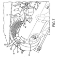
FIG. 7 illustrates a view of a landing gear electrical swivel installed on a landing gear in the gear-down position, in accordance with various embodiments; -
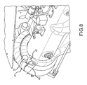
FIG. 8 illustrates a view of a landing gear electrical swivel having a cover and installed on a landing gear in the gear-down position, in accordance with various embodiments; -
FIG. 9 illustrates a view of a landing gear electrical swivel having a cover and installed on a landing gear in the gear-up position, in accordance with various embodiments; and -
FIGS. 10-11 illustrate detail views of the electrical contacts of a landing gear electrical swivel in accordance with various embodiments. - The detailed description of exemplary embodiments herein makes reference to the accompanying drawings, which show exemplary embodiments by way of illustration and their best mode. While these exemplary embodiments are described in sufficient detail to enable those skilled in the art to practice the inventions, it should be understood that other embodiments may be realized and that logical, chemical and mechanical changes may be made without departing from the scope of the disclosure. Thus, the detailed description herein is presented for purposes of illustration only and not of limitation. For example, the steps recited in any of the method or process descriptions may be executed in any order and are not necessarily limited to the order presented.
- Furthermore, any reference to singular includes plural embodiments, and any reference to more than one component or step may include a singular embodiment or step. Also, any reference to attached, fixed, connected or the like may include permanent, removable, temporary, partial, full and/or any other possible attachment option. Additionally, any reference to without contact (or similar phrases) may also include reduced contact or minimal contact.
- As used herein, phrases such as "make contact with," "coupled to," "touch," "interface with" and "engage" may be used interchangeably.
- In various embodiments, the present disclosure provides an electrical swivel system with reduced footprint. In this regard, a single electrical swivel system may conduct multiple currents and signals while beneficially decreasing the space in the landing gear storage bay occupied by the conducting hardware.
- In various embodiments, an aircraft landing gear system may comprise a landing gear, an electrical swivel system, and an airframe. Moreover, an electrical swivel system may comprise a movable swivel member and a fixed swivel member. For example, with reference to
Fig. 1 , an aircraftlanding gear system 5 comprises alanding gear 50, anairframe 60, and anelectrical swivel system 10 comprising a movableswivel member 20 and a fixedswivel member 30. - In various embodiments, a movable swivel member may comprise an external gear connector, a movable member interface apparatus, and a movable member mounting apparatus. For example, with reference to
Figs. 1 ,2 ,4 , and6 , in various embodiments, a movableswivel member 20 comprises alanding gear connector 25, a movablemember interface apparatus 26, and a movablemember mounting apparatus 29. - Similarly, in various embodiments, a fixed swivel member may comprise an external aircraft connector, a fixed member interface apparatus, and a fixed member mounting apparatus. For example, with reference to
Figs. 1 ,3 ,5 , and6 , in various embodiments, a fixedswivel member 30 may comprise anexternal aircraft connector 35, a fixedmember interface apparatus 36, and a fixedmember mounting apparatus 39. - With reference to
Fig. 1 , movablemember mounting apparatus 29 may mechanically attach movableswivel member 20 to landinggear 50. Similarly, fixedmember mounting apparatus 39 may mechanically attach fixedswivel member 30 toairframe 60. In this manner, movableswivel member 20 may move with the landing gear as it extends and retracts, while fixedswivel member 30 may remain stationary with respect to theairframe 60. Movableswivel member 20 and fixedswivel member 30 may be in movable mechanical communication, so that an electrical current or signal may be passed between components of movableswivel member 20 and components of fixedswivel member 30, even while movableswivel member 20 moves relative to fixedswivel member 30, for example, upon extension or retraction oflanding gear 50 relative toairframe 60. - In various embodiments, movable
member mounting apparatus 29 may comprise apertures and bolts, or may comprise welds, rivets, quick release fasteners, or may comprise any other mechanism by which the movableswivel member 20 may be mounted to thelanding gear 50. Similarly, in various embodiments, fixedmember mounting apparatus 39 may comprise apertures and bolts, or may comprise welds, rivets, quick release fasteners, or may comprise any other mechanism by which the fixedswivel member 30 may be mounted to theairframe 60. - As mentioned above, in various embodiments, movable
swivel member 20 may also comprise an external gear connector. In various embodiments, fixedswivel member 30 may also comprise an external aircraft connector. For example, with reference toFigs. 6-7 , movableswivel member 20 may comprise alanding gear connector 25 and a movablemember interface apparatus 26. Fixedswivel member 30 may comprise anexternal aircraft connector 35 and a fixedmember interface apparatus 36. - A current or signal may be introduced at
external aircraft connector 35 and conducted to fixedmember interface apparatus 36, by internal wiring, for example, by wires, circuit board traces, and/or wire brushes. Fixedmember interface apparatus 36 is mounted in rotatable mechanical communication with movablemember interface apparatus 26, thus the current or signal is electrically conducted from components of fixedmember interface apparatus 36 to corresponding components of movablemember interface apparatus 26 regardless of the position to which movablemember interface apparatus 26 is rotated. The current is then conducted from movablemember interface apparatus 26 tolanding gear connector 25 by internal wiring, for example, wires, circuit board traces, and/or wire brushes. In this manner, an electrical connection is substantially and continuously maintained across the landing gear joint, even when the landing gear is in motion between a gear-up and gear-down position. For example,Fig. 6 illustrates various elements when thelanding gear 50 is in a gear-up position, andFig. 7 illustrates these various elements when thelanding gear 50 is in a gear-down position. - In various embodiments,
landing gear connector 25 andexternal aircraft connector 35 may comprise signal connectors, or power connectors, or connectors conveying both signals and power. In various embodiments,external aircraft connector 35 andlanding gear connector 25 may comprise connectors specified under Aeronautical Radio, Inc. (ARINC) standards. In various embodiments,external aircraft connector 35 andlanding gear connector 25 may comprise an Amphenol Aerospace connector, available from Amphenol Corporation, Wallingford, CT. In various embodiments,external aircraft connector 35 andlanding gear connector 25 may comprise connectors from the D3999 connector series, although any suitable connector adapted for a desired operating environment may be used. - As mentioned above, in various embodiments, a fixed
swivel member 30 may comprise a fixedmember interface apparatus 36 and amovable swivel member 20 may comprise a movablemember interface apparatus 26. With reference toFigs. 10-11 , a fixedswivel member 30 may comprise a fixedmember interface apparatus 36 comprising a fixedtrack 38. Fixedtrack 38 may comprise electrical contacts adapted to interface with corresponding electrical contacts onmovable swivel member 20. For instance,movable swivel member 20 may comprise a movablemember interface apparatus 26 comprising amovable track 28.Movable track 28 may comprise electrical contacts adapted to interface with corresponding electrical contacts on fixedswivel member 30. - With particular reference to
Fig. 10 , in various embodiments, movablemember interface apparatus 26 may comprisemovable track 28 comprising a series ofbosses 43 andvalleys 44. Similarly, fixedmember interface apparatus 36 may comprise a fixedtrack 38 comprising a series ofbosses 43 andvalleys 44 adapted to correspond to those ofmovable track 28. For example, with reference toFig. 10 , eachboss 43 lands in a correspondingvalley 44. In various embodiments,movable track 28 may comprise at least one electrical contact. For example, anelectrical contact 21 may be placed on the upper sidewall of aboss 43. In various embodiments thiselectrical contact 21 conducts signals or current to anelectrical contact 31 placed on a corresponding sidewall of avalley 44 of fixedtrack 38 adapted to correspond tomovable track 28. In a similar manner,electrical contact 23 may be placed on a sidewall of avalley 44 ofmovable track 28 adapted to correspond toelectrical contact 33 of fixedtrack 38. - In similar manner, contacts may be placed on the top of a
boss 43 and the floor of avalley 44. For example, in various embodiments, anelectrical contact 22 may be placed on the top side of aboss 43. In various embodiments thiselectrical contact 22 conducts signals or current toelectrical contact 32 placed on a corresponding bottom of avalley 44 of fixedtrack 38 adapted to correspond tomovable track 28 of movablemember interface apparatus 26. - In various embodiments,
electrical contact 21 andelectrical contact 31 may conduct a different current or signal thanelectrical contact 22 andelectrical contact 32. In various embodiments,electrical contact 21 andelectrical contact 31 may conduct a different current or signal thanelectrical contact 23 andelectrical contact 33. Alternatively, any number of contacts may conduct the same current or signal, or different currents or signals, depending on the properties desired. For example, multiple pairs of contacts may conduct the same current or signal in order to increase the current handling capacity of a circuit, or to decrease parasitic effects, or to achieve other desired electrical or magnetic behaviors. In various embodiments, 8 discrete signals/currents are conducted by an electrical swivel system. - With particular reference to
Fig. 11 , in various embodiments, movablemember interface apparatus 26 may comprisemovable track 28 comprising a substantially planar surface. Similarly, fixedmember interface apparatus 36 may comprise a fixedtrack 38 comprising a substantially planar surface. In various embodiments,movable track 28 may comprise at least one electrical contact. For example, anelectrical contact 24 may be placed on the planar surface ofmovable track 28. In various embodiments thiselectrical contact 24 conducts signals or current to anelectrical contact 34 placed on a corresponding planar surface of fixedtrack 38 adapted to correspond tomovable track 28. - In various embodiments, electrical contacts may be arranged in any manner adapted to maintain electrical continuity while the landing gear moves. For instance, in various embodiments, fixed
track 38 andmovable track 28 may comprise triangular ridges and troughs, or any shape, or a combination of shapes. Furthermore, fixedtrack 38 andmovable track 28 may comprise shielding members, for example, unused troughs and/or valleys and/or grounded troughs and/or valleys. In various embodiments, interface apparatuses may comprise unused contacts and, optionally, shielding members, for instance, to ameliorate crosstalk, or to ameliorate parasitic inductance or capacitance, or to ameliorate arcing. In various embodiments, a fixedmember interface apparatus 36 and/or movablemember interface apparatus 26 may comprise shielding, for example, to provide isolation between classified and unclassified signals, or to provide isolation between high currents and small signals, or to satisfy Emission Security (EMSEC) standards, for example, to satisfy TEMPEST standards. - As discussed above, in various embodiments, a movable swivel member may comprise a tension member. For example, with reference to
Fig. 2 , amovable swivel member 20 may comprise atension member 27 disposed between movablemember interface apparatus 26 andmovable track 28. In various embodiments, thetension member 27 is a spring. In this manner, force may be applied by atension member 27 tomovable track 28 to impel it to maintain electrical connectivity with fixed swivel member 30 (seeFig. 1 ). In various embodiments, aseparate tension member 27 exists for eachmovable track 28, for example, so that each electrical contact is separately tensioned. - In various embodiments, a fixed swivel member may comprise a tension member. For example, with reference to
Fig. 3 , a fixedswivel member 30 may comprise atension member 37 disposed between fixedmember interface apparatus 36 and fixedtrack 38. In various embodiments, thetension member 37 is a spring. In this manner, force may be applied by atension member 37 to fixedtrack 38 to impel it to maintain electrical connectivity with movable swivel member 20 (seeFig. 1 ). In various embodiments, aseparate tension member 37 exists for each fixedtrack 38, for example, so each electrical contact is separately tensioned. - With reference to
Fig. 4 , in other various embodiments, atension member 27 of amovable swivel member 20 may be disposed between a movablemember mounting apparatus 29 and movablemember interface apparatus 26. In this manner, force may be applied by atension member 27 to movablemember interface apparatus 26 to impel eachmovable track 28 to maintain electrical connectivity with fixed swivel member 30 (seeFig. 1 ). In various embodiments, asingle tension member 27 exists for more than onemovable track 28, for example, so that multiple electrical contacts are jointly tensioned. - With reference to
Fig. 5 , in various embodiments, atension member 37 of a fixedswivel member 30 may be disposed between a fixedmember mounting apparatus 39 and fixedmember interface apparatus 36. In this manner, force may be applied by atension member 37 to fixedmember interface apparatus 36 to impel each fixedtrack 38 to maintain electrical connectivity with movable swivel member 20 (seeFig. 1 ). In various embodiments, asingle tension member 37 exists for more than one fixedtrack 38, for example, so multiple electrical contacts are jointly tensioned. - Thus, as one having ordinary skill in the art will appreciate, both the fixed swivel member and the movable swivel member may have tension members, or one may have a tension member and the other may not have a tension member. Moreover, one may have a single tension member for multiple fixed tracks or movable tracks, and one may have a separate tension member for each fixed track or movable track, or both may each have a single tension member for multiple fixed tracks or multiple movable tracks, or both may have a separate tension member for each fixed track or movable track. In this manner, any arrangement or combination of embodiments of tension members may be implemented.
- Moreover, one having ordinary skill in the art will appreciate that a tension member may comprise a spring. In other various embodiments, a tension member may comprise an inherent elasticity manufactured into an electrical contact, for example, the contact may comprise a compressible bent portion whereby force may be exerted on the tip of the contact. Moreover, in various embodiments, the contact comprises a wire brush.
- In various embodiments, an
electrical swivel system 10 may comprise a cover, for example, to protect various aspects of the system from the elements, for example dirt, dust, grease, water, and other environmental concerns. With reference toFigs. 8-9 , an electrical swivel system is illustrated further comprising acover 40. In various embodiments, thecover 40 comprises afirst rubber portion 41 and asecond rubber portion 42. In various embodiments, the cover substantially wraps around theelectrical swivel system 10, for example, afirst rubber portion 41 wrapping around one portion and asecond rubber portion 42 wrapping around a second portion. In this manner,landing gear connector 25 may move while extended betweenfirst rubber portion 41 andsecond rubber portion 42 whileelectrical swivel system 10 remains substantially sealed. However, in various embodiments, the cover may comprise a metal cover, for example, a piece of pressed sheet metal bent to encompass the entire electrical swivel system. In various embodiments, the cover may also provide electrical shielding. - In various embodiments, the movable swivel member and the fixed swivel member comprise complementary shapes. For example, with reference to
Fig. 7 , themovable swivel member 20 and the fixedswivel member 30 may comprise complementary shapes so that themovable swivel member 20 may nest within the fixedswivel member 30. In various embodiments, to "nest" means that a portion of one member passes through a plane of at least a portion of the other member. In various embodiments, themovable swivel member 20 may nest in a portion of the fixedswivel member 30 as depicted inFig. 7 . In various embodiments, with reference toFig. 10 , thebosses 43 may be said to nest within thevalleys 44. - In various embodiments, with reference to
Fig. 7 , the fixedswivel member 30 may comprise a first arc length. In other words, the fixedswivel member 30 may be shaped to follow a portion of the circumference of a circle. A fixedswivel member 30 may comprise an arc length of a circle centered on same axis as thelanding gear 50. In this manner, the fixedswivel member 30 may comprise an arc length of a circle having a center disposed coincident with the axis about whichlanding gear 50 moves. In various embodiments,movable swivel member 20 may comprise a second arc length wherein the second arc length is shorter than the first arc length. In other words, the movable swivel member may be shaped to follow a portion of the circumference of the circle. A movable swivel member may comprise an arc length of the circle centered on the same axis as thelanding gear 50. However, themovable swivel member 20 may comprise a shorter arc length than the fixedswivel member 30. In this manner, themovable swivel member 20 may curve identically to the fixedswivel member 30, but may be shorter than the fixedswivel member 30 so that it can travel to different points along fixedswivel member 30. - Thus, in various embodiments, the fixed
swivel member 30 comprises a first arc length having afirst end 45 and asecond end 46 as depicted inFig. 7 . In various embodiments, themovable swivel member 20 travels between the first end and the second end of the fixed swivel member in response to the landing gear extending/retracting. - Now, having described various components of electrical swivel systems, an electrical swivel system may be manufactured from various materials. In various embodiments, an electrical swivel system may comprise metal. An electrical swivel system may comprise aluminum, titanium, tungsten, carbon steel, copper, or stainless steel, though it may further comprise numerous other materials configured to provide desirable characteristics. In various embodiments, various portions of electrical swivel system as disclosed herein are made of different materials or combinations of materials, and/or may comprise coatings.
- In various embodiments, electrical swivel system may comprise multiple materials, or any material configuration suitable to enhance or reinforce the resiliency and/or support of the system when subjected to wear in an operating environment or to satisfy other desired electromagnetic, chemical, physical, or biological properties such as durability, signal isolation, dielectric constant, impedance, resistance, parasitic capacitance, parasitic inductance, parasitic diode effects, current handling capability, thermal dissipation, and footprint constraints, among others.
- For example, in various embodiments, the mounting apparatus, and/or a cover, and/or a tension member may comprise metals. In various embodiments, an interface apparatus may comprise a ceramic, or may comprise a plastic, or may comprise a metal with insulating coatings or sleeves, for example, to prevent contacts from shorting out.
- In various embodiments, while the electrical swivel systems described herein have been described in the context of aircraft applications, one will appreciate in light of the present disclosure, that the systems described herein may be used on various other applications wherein electrical connectivity is needed across structures moving with respect to each other. For example, the systems described herein may be used on propulsion systems, robotics systems, and industrial systems or processes.
- Benefits, other advantages, and solutions to problems have been described herein with regard to specific embodiments. Furthermore, the connecting lines shown in the various figures contained herein are intended to represent exemplary functional relationships and/or physical couplings between the various elements. It should be noted that many alternative or additional functional relationships or physical connections may be present in a practical system. However, the benefits, advantages, solutions to problems, and any elements that may cause any benefit, advantage, or solution to occur or become more pronounced are not to be construed as critical, required, or essential features or elements of the inventions. The scope of the inventions is accordingly to be limited by nothing other than the appended claims, in which reference to an element in the singular is not intended to mean "one and only one" unless explicitly so stated, but rather "one or more." Moreover, where a phrase similar to "at least one of A, B, or C" is used in the claims, it is intended that the phrase be interpreted to mean that A alone may be present in an embodiment, B alone may be present in an embodiment, C alone may be present in an embodiment, or that any combination of the elements A, B and C may be present in a single embodiment; for example, A and B, A and C, B and C, or A and B and C.
- Systems, methods and apparatus are provided herein. In the detailed description herein, references to "one embodiment", "an embodiment", "various embodiments", etc., indicate that the embodiment described may include a particular feature, structure, or characteristic, but every embodiment may not necessarily include the particular feature, structure, or characteristic. Moreover, such phrases are not necessarily referring to the same embodiment. Further, when a particular feature, structure, or characteristic is described in connection with an embodiment, it is submitted that it is within the knowledge of one skilled in the art to affect such feature, structure, or characteristic in connection with other embodiments whether or not explicitly described. After reading the description, it will be apparent to one skilled in the relevant art(s) how to implement the disclosure in alternative embodiments.
- Furthermore, no element, component, or method step in the present disclosure is intended to be dedicated to the public regardless of whether the element, component, or method step is explicitly recited in the claims. No claim element herein is to be construed under the provisions of 35 U.S.C. 112(f), unless the element is expressly recited using the phrase "means for." As used herein, the terms "comprises", "comprising", or any other variation thereof, are intended to cover a non-exclusive inclusion, such that a process, method, article, or apparatus that comprises a list of elements does not include only those elements but may include other elements not expressly listed or inherent to such process, method, article, or apparatus.
Claims (15)
- An electrical swivel system (10) comprising:a movable swivel member (20) comprising:a movable member mounting apparatus (29) adapted to mount the movable swivel member (20) to a landing gear (50);an external gear connector (25) through which electrical signals may be conducted;a movable member interface apparatus (26);a fixed swivel member (30) comprising:a fixed member mounting apparatus (39) adapted to mount the fixed swivel member (30) to an airframe (60);an external aircraft connector (35) through which electrical signals may be conducted; anda fixed member interface apparatus (36);wherein the movable member interface apparatus (26) comprises a movable track (28) comprising a moveable track electrical contact,wherein the fixed member interface apparatus (36) comprises a fixed track (38) comprising a fixed track electrical contact,wherein the movable track electrical contact contacts the fixed track electrical contact so that electrical current may be conducted therebetween,wherein the movable swivel member (20) and the fixed swivel member (30) comprise complementary shapes whereby the movable swivel member (20) nests within the fixed swivel member (30), andwherein the movable swivel member (20) travels along an arc length between a first end (45) of the fixed swivel member (30) and a second end (46) of the fixed swivel member (30).
- The electrical swivel system according to claim 1, wherein the movable swivel member (20) further comprises a tension member (27) disposed between the movable member mounting apparatus (29) and the movable member interface apparatus (26) whereby force is exerted on the moveable track electrical contact.
- The electrical swivel system according to claim 1 or 2, wherein the fixed swivel member (30) further comprises a tension member (37) disposed between the fixed member mounting apparatus (39) and the fixed member interface apparatus (36) whereby force is exerted on the fixed track electrical contact.
- The electrical swivel system according to claim 2 or 3, wherein the tension member (27,37) comprises a spring.
- The electrical swivel system according to any preceding claim, further comprising a cover (40).
- The electrical swivel system according to claim 5, wherein the cover comprises a first rubber portion (41) substantially wrapped around a first portion of the electrical swivel system (10) and a second rubber portion (42) substantially wrapped around a second portion of the electrical swivel system (10).
- The electrical swivel system according to any preceding claim, wherein at least one of the fixed track (38) and the movable track (28) comprise a planar surface.
- The electrical swivel system according to any preceding claim, wherein the movable track (28) comprises a series of bosses (43).
- The electrical swivel system according to claim 8, wherein the movable track electrical contact is positioned on sidewall of at least one of the series of bosses (43).
- The electrical swivel system according to claim 8 or 9, wherein the fixed track electrical contact is positioned on sidewall of at least one of the series of bosses (43).
- An aircraft landing gear system (5) comprising:a landing gear (50) comprising a first portion of an electrical system;an airframe comprising a second portion of the electrical system; andan electrical swivel system (10) comprising a movable swivel member (20) in electrical communication with the first portion of the electrical system and a fixed swivel member (30) in electrical communication with the second portion of the electrical system,whereby electric signals are conducted from the first portion of the electrical system to the second portion of the electrical system,wherein the movable swivel member (20) travels along an arc length between a first end (45) of the fixed swivel member (30) and a second end (46) of the fixed swivel member (30), andwherein the movable swivel member (20) and the fixed swivel member (30) comprise complementary shapes whereby the movable swivel member (20) nests within the fixed swivel member (30).
- The aircraft landing gear system according to claim 11,
wherein the movable swivel member (20) comprises:a movable member mounting apparatus (29) adapted to mount the movable swivel member (20) to the landing gear (50);an external gear connector (25) in electrical communication with the first portion of the electrical system and through which electrical signals may be conducted;a movable member interface apparatus (26);wherein the fixed swivel member (30) comprises:a fixed member mounting apparatus (39) adapted to mount the fixed swivel member (30) to the airframe (60);an external aircraft connector (35) in electrical communication with the second portion of the electrical system and through which electrical signals may be conducted; anda fixed member interface apparatus (36);wherein the movable member interface apparatus (26) comprises a movable track (28) comprising a movable track electrical contact,
wherein the fixed member interface apparatus (36) comprises a fixed track (38) comprising a fixed track electrical contact, and
wherein the movable track electrical contact contacts the fixed track electrical contact so that electrical current may be conducted therebetween. - The aircraft landing gear system according to claim 12, wherein the movable swivel member (20) further comprises a tension member (27) disposed between the movable member mounting apparatus (29) and the movable member interface apparatus (26) whereby force is exerted on the moveable track electrical contact.
- The aircraft landing gear system according to claim 12 or 13, wherein the fixed swivel member (30) further comprises a tension member (37) disposed between the fixed member mounting apparatus (39) and the fixed member interface apparatus (36) whereby force is exerted on the fixed track electrical contact.
- The aircraft landing gear system according to any of claims 11 to 14, wherein the electrical swivel system (10) further comprises a cover (40).
Applications Claiming Priority (1)
| Application Number | Priority Date | Filing Date | Title |
|---|---|---|---|
| US14/223,882 US9214777B2 (en) | 2014-03-24 | 2014-03-24 | Landing gear electrical swivel |
Publications (1)
| Publication Number | Publication Date |
|---|---|
| EP2924816A1 true EP2924816A1 (en) | 2015-09-30 |
Family
ID=52705991
Family Applications (1)
| Application Number | Title | Priority Date | Filing Date |
|---|---|---|---|
| EP15158460.4A Withdrawn EP2924816A1 (en) | 2014-03-24 | 2015-03-10 | Landing gear electrical swivel |
Country Status (2)
| Country | Link |
|---|---|
| US (2) | US9214777B2 (en) |
| EP (1) | EP2924816A1 (en) |
Families Citing this family (3)
| Publication number | Priority date | Publication date | Assignee | Title |
|---|---|---|---|---|
| US9214777B2 (en) * | 2014-03-24 | 2015-12-15 | Goodrich Corporation | Landing gear electrical swivel |
| GB2593447A (en) * | 2020-03-11 | 2021-09-29 | Airbus Operations Ltd | Aircraft systems and electrical connection apparatus |
| CN114577254B (en) * | 2022-05-07 | 2022-09-09 | 成都凯天电子股份有限公司 | High reliability detection method and system based on landing gear inductive proximity sensor |
Citations (4)
| Publication number | Priority date | Publication date | Assignee | Title |
|---|---|---|---|---|
| EP0716481A2 (en) * | 1994-12-08 | 1996-06-12 | Hughes Aircraft Company | Rotary electrical connector |
| US5704792A (en) * | 1995-05-22 | 1998-01-06 | Hughes Aircraft Company | Spring loaded rotary connector |
| GB2459199A (en) * | 2008-04-18 | 2009-10-21 | Boeing Co | A tip alarm system for an aircraft |
| WO2012084218A2 (en) * | 2010-12-20 | 2012-06-28 | Liebherr-Aerospace Lindenberg Gmbh | Landing gear for an aircraft |
Family Cites Families (33)
| Publication number | Priority date | Publication date | Assignee | Title |
|---|---|---|---|---|
| US2404969A (en) * | 1944-07-07 | 1946-07-30 | Westinghouse Electric Corp | Electrical machine |
| US4137474A (en) * | 1974-06-04 | 1979-01-30 | Kraftwerk Union Aktiengesellschaft | Gas-cooled slip ring for electrical machines |
| DE3164200D1 (en) * | 1980-11-13 | 1984-07-19 | Bbc Brown Boveri & Cie | Slip-ring device for electrical machines |
| US5104063A (en) * | 1990-04-27 | 1992-04-14 | Hartley James M | Aircraft landing gear prerotation system |
| US5054189A (en) * | 1990-10-25 | 1991-10-08 | Litton Systetms, Inc. | Method of manufacturing an electrical slip ring assembly |
| US5734218A (en) * | 1996-05-13 | 1998-03-31 | Litton Systems, Inc. | Electrical slip ring and method of manufacturing same |
| CA2228089A1 (en) * | 1997-04-14 | 1998-10-14 | Max Salzberg | Rotatable electrical connector assembly |
| NL1017236C2 (en) * | 2001-01-30 | 2002-07-31 | Ocu Technologies B V | Rotation connector and a method for manufacturing such a connector. |
| US6664697B2 (en) * | 2001-12-13 | 2003-12-16 | Northrop Grumman Corporation | Electrical slip ring apparatus having multiple spaced apart support structures |
| FR2857169B1 (en) * | 2003-07-01 | 2006-02-24 | Cit Alcatel | METHOD FOR MANUFACTURING ELECTRICALLY CONDUCTIVE ISOLATED ROTATING COLLECTOR ELEMENTS AND ROTATING COLLECTOR COMPRISING THESE ELECTRICALLY CONDUCTIVE ELEMENTS |
| US7114681B2 (en) * | 2004-06-03 | 2006-10-03 | The Boeing Company | Landing assist apparatus with offset landing probe |
| US7252266B2 (en) * | 2004-06-03 | 2007-08-07 | The Boeing Company | Landing assist apparatus eccentric bushing |
| US20050279882A1 (en) * | 2004-06-03 | 2005-12-22 | Muylaert Neal W | Landing assist probe retention strap |
| US7028949B2 (en) * | 2004-06-03 | 2006-04-18 | The Boeing Company | Landing assist probe mounting system |
| US20050279885A1 (en) * | 2004-06-03 | 2005-12-22 | Darrin Tebon | Landing assist apparatus with releasable slip ring |
| US7198226B2 (en) * | 2004-06-03 | 2007-04-03 | The Boeing Company | Landing assist apparatus retention strap spool |
| US7344108B2 (en) * | 2004-06-03 | 2008-03-18 | The Boeing Company | Landing assist apparatus interface bulkhead and method of installation |
| NO20044873D0 (en) * | 2004-11-09 | 2004-11-09 | Framo Eng As | EL power / signal transmission system |
| US7594626B2 (en) * | 2006-06-08 | 2009-09-29 | Rod F. Soderberg | Magnetically induced aircraft landing wheel rotation |
| US7559767B2 (en) * | 2007-05-15 | 2009-07-14 | Moog Inc. | High-frequency drum-style slip-ring modules |
| TWM331247U (en) * | 2007-10-05 | 2008-04-21 | Taiwan Long Hawn Entpr Co | Assembly slip ring |
| DK200801474A (en) * | 2008-10-27 | 2009-11-19 | Vestas Wind Sys As | Slip ring assembly with shaft holder |
| GB0911016D0 (en) * | 2009-06-25 | 2009-08-12 | Airbus Operations Ltd | Electrical power transmitting telescopic strut |
| ES2453866T3 (en) * | 2009-08-13 | 2014-04-08 | Alstom Renewable Technologies | Arrangement of slip rings for a rotary electric machine |
| US8025506B2 (en) * | 2010-01-20 | 2011-09-27 | Teledyne Odi, Inc. | Harsh environment rotary joint electrical connector |
| US9021684B2 (en) * | 2011-04-19 | 2015-05-05 | Tyco Electronics Corporation | Method of fabricating a slip ring component |
| DE102012200561A1 (en) * | 2012-01-16 | 2013-07-18 | Wobben Properties Gmbh | A slip ring transmission |
| FR3008956B1 (en) * | 2013-07-26 | 2018-05-04 | Safran Landing Systems | DEVICE FOR DRIVING ROTATION OF AN AIRCRAFT WHEEL |
| EP2843778B1 (en) * | 2013-09-02 | 2018-06-27 | LTN Servotechnik GmbH | Slip ring unit and method for monitoring the state of a slip ring unit |
| US9334850B2 (en) * | 2013-09-05 | 2016-05-10 | General Electric Company | System and method for centering wye ring in-situ |
| US10038357B2 (en) * | 2013-10-16 | 2018-07-31 | General Electric Company | Method for repairing or servicing a wye ring |
| US9391417B2 (en) * | 2013-11-13 | 2016-07-12 | Halliburton Energy Services, Inc. | Hydroplaning reducing slip ring apparatus |
| US9214777B2 (en) * | 2014-03-24 | 2015-12-15 | Goodrich Corporation | Landing gear electrical swivel |
-
2014
- 2014-03-24 US US14/223,882 patent/US9214777B2/en not_active Expired - Fee Related
-
2015
- 2015-03-10 EP EP15158460.4A patent/EP2924816A1/en not_active Withdrawn
- 2015-11-03 US US14/930,956 patent/US9315260B2/en not_active Expired - Fee Related
Patent Citations (4)
| Publication number | Priority date | Publication date | Assignee | Title |
|---|---|---|---|---|
| EP0716481A2 (en) * | 1994-12-08 | 1996-06-12 | Hughes Aircraft Company | Rotary electrical connector |
| US5704792A (en) * | 1995-05-22 | 1998-01-06 | Hughes Aircraft Company | Spring loaded rotary connector |
| GB2459199A (en) * | 2008-04-18 | 2009-10-21 | Boeing Co | A tip alarm system for an aircraft |
| WO2012084218A2 (en) * | 2010-12-20 | 2012-06-28 | Liebherr-Aerospace Lindenberg Gmbh | Landing gear for an aircraft |
Also Published As
| Publication number | Publication date |
|---|---|
| US9214777B2 (en) | 2015-12-15 |
| US20160052622A1 (en) | 2016-02-25 |
| US9315260B2 (en) | 2016-04-19 |
| US20150270672A1 (en) | 2015-09-24 |
Similar Documents
| Publication | Publication Date | Title |
|---|---|---|
| US9315260B2 (en) | Landing gear electrical swivel | |
| JP6495825B2 (en) | Connection device | |
| JP6552415B2 (en) | Sleeve for power cable | |
| US10462928B2 (en) | Composite cable assembly and server having the same | |
| US11862902B2 (en) | Electrical connector with electromagnetic shielding function | |
| US20180219305A1 (en) | High power module interfaces | |
| US7699635B2 (en) | Randomly-accessible electrical busbar with protective cover and associated mating connector | |
| EP4055696B1 (en) | Electrical windings for a low pressure environment | |
| EP2816361A1 (en) | Conductor assembly | |
| US9490600B2 (en) | High current slipring for multi fiber brushes | |
| EP3236536B1 (en) | Zipper-type electrical connector | |
| CN103026554A (en) | Electrical connector and electrical equipment comprising the same | |
| CN107039105B (en) | Cable, method for manufacturing cable and method for bundling cables | |
| US3027417A (en) | Extensible electric cable | |
| US20140138121A1 (en) | Isolation system for an electronic device | |
| US9579806B2 (en) | Robotic power and signal distribution using laminated cable with separator webs | |
| CN109119782B (en) | Removable power connection for power | |
| US20150162114A1 (en) | Structural integrated wiring loom | |
| US10359140B2 (en) | Feedback bulkhead connector assembly | |
| US9406462B2 (en) | Truss interconnect | |
| US9818506B2 (en) | Flexible low impedance power bus | |
| EP3652813B1 (en) | Electrical connector | |
| US8704102B2 (en) | Printed flexible multilayer twisted-pair shielded high speed data cable | |
| US20190195911A1 (en) | Electrical probe | |
| US10651814B2 (en) | Conductive path with noise filter |
Legal Events
| Date | Code | Title | Description |
|---|---|---|---|
| PUAI | Public reference made under article 153(3) epc to a published international application that has entered the european phase |
Free format text: ORIGINAL CODE: 0009012 |
|
| AK | Designated contracting states |
Kind code of ref document: A1 Designated state(s): AL AT BE BG CH CY CZ DE DK EE ES FI FR GB GR HR HU IE IS IT LI LT LU LV MC MK MT NL NO PL PT RO RS SE SI SK SM TR |
|
| AX | Request for extension of the european patent |
Extension state: BA ME |
|
| 17P | Request for examination filed |
Effective date: 20160324 |
|
| RBV | Designated contracting states (corrected) |
Designated state(s): AL AT BE BG CH CY CZ DE DK EE ES FI FR GB GR HR HU IE IS IT LI LT LU LV MC MK MT NL NO PL PT RO RS SE SI SK SM TR |
|
| STAA | Information on the status of an ep patent application or granted ep patent |
Free format text: STATUS: EXAMINATION IS IN PROGRESS |
|
| 17Q | First examination report despatched |
Effective date: 20170731 |
|
| STAA | Information on the status of an ep patent application or granted ep patent |
Free format text: STATUS: THE APPLICATION IS DEEMED TO BE WITHDRAWN |
|
| 18D | Application deemed to be withdrawn |
Effective date: 20191001 |