EP2924767A2 - Rechargeable battery - Google Patents
Rechargeable battery Download PDFInfo
- Publication number
- EP2924767A2 EP2924767A2 EP14199055.6A EP14199055A EP2924767A2 EP 2924767 A2 EP2924767 A2 EP 2924767A2 EP 14199055 A EP14199055 A EP 14199055A EP 2924767 A2 EP2924767 A2 EP 2924767A2
- Authority
- EP
- European Patent Office
- Prior art keywords
- terminal
- plate
- hole
- electrode
- rechargeable battery
- Prior art date
- Legal status (The legal status is an assumption and is not a legal conclusion. Google has not performed a legal analysis and makes no representation as to the accuracy of the status listed.)
- Withdrawn
Links
Images

Classifications
-
- H—ELECTRICITY
- H01—ELECTRIC ELEMENTS
- H01M—PROCESSES OR MEANS, e.g. BATTERIES, FOR THE DIRECT CONVERSION OF CHEMICAL ENERGY INTO ELECTRICAL ENERGY
- H01M50/00—Constructional details or processes of manufacture of the non-active parts of electrochemical cells other than fuel cells, e.g. hybrid cells
- H01M50/10—Primary casings; Jackets or wrappings
- H01M50/147—Lids or covers
-
- H—ELECTRICITY
- H01—ELECTRIC ELEMENTS
- H01M—PROCESSES OR MEANS, e.g. BATTERIES, FOR THE DIRECT CONVERSION OF CHEMICAL ENERGY INTO ELECTRICAL ENERGY
- H01M50/00—Constructional details or processes of manufacture of the non-active parts of electrochemical cells other than fuel cells, e.g. hybrid cells
- H01M50/50—Current conducting connections for cells or batteries
- H01M50/528—Fixed electrical connections, i.e. not intended for disconnection
-
- H—ELECTRICITY
- H01—ELECTRIC ELEMENTS
- H01M—PROCESSES OR MEANS, e.g. BATTERIES, FOR THE DIRECT CONVERSION OF CHEMICAL ENERGY INTO ELECTRICAL ENERGY
- H01M50/00—Constructional details or processes of manufacture of the non-active parts of electrochemical cells other than fuel cells, e.g. hybrid cells
- H01M50/10—Primary casings; Jackets or wrappings
- H01M50/172—Arrangements of electric connectors penetrating the casing
- H01M50/174—Arrangements of electric connectors penetrating the casing adapted for the shape of the cells
- H01M50/176—Arrangements of electric connectors penetrating the casing adapted for the shape of the cells for prismatic or rectangular cells
-
- H—ELECTRICITY
- H01—ELECTRIC ELEMENTS
- H01M—PROCESSES OR MEANS, e.g. BATTERIES, FOR THE DIRECT CONVERSION OF CHEMICAL ENERGY INTO ELECTRICAL ENERGY
- H01M50/00—Constructional details or processes of manufacture of the non-active parts of electrochemical cells other than fuel cells, e.g. hybrid cells
- H01M50/50—Current conducting connections for cells or batteries
- H01M50/531—Electrode connections inside a battery casing
-
- H—ELECTRICITY
- H01—ELECTRIC ELEMENTS
- H01M—PROCESSES OR MEANS, e.g. BATTERIES, FOR THE DIRECT CONVERSION OF CHEMICAL ENERGY INTO ELECTRICAL ENERGY
- H01M50/00—Constructional details or processes of manufacture of the non-active parts of electrochemical cells other than fuel cells, e.g. hybrid cells
- H01M50/50—Current conducting connections for cells or batteries
- H01M50/543—Terminals
-
- H—ELECTRICITY
- H01—ELECTRIC ELEMENTS
- H01M—PROCESSES OR MEANS, e.g. BATTERIES, FOR THE DIRECT CONVERSION OF CHEMICAL ENERGY INTO ELECTRICAL ENERGY
- H01M50/00—Constructional details or processes of manufacture of the non-active parts of electrochemical cells other than fuel cells, e.g. hybrid cells
- H01M50/50—Current conducting connections for cells or batteries
- H01M50/543—Terminals
- H01M50/552—Terminals characterised by their shape
- H01M50/553—Terminals adapted for prismatic, pouch or rectangular cells
-
- H—ELECTRICITY
- H01—ELECTRIC ELEMENTS
- H01M—PROCESSES OR MEANS, e.g. BATTERIES, FOR THE DIRECT CONVERSION OF CHEMICAL ENERGY INTO ELECTRICAL ENERGY
- H01M50/00—Constructional details or processes of manufacture of the non-active parts of electrochemical cells other than fuel cells, e.g. hybrid cells
- H01M50/50—Current conducting connections for cells or batteries
- H01M50/543—Terminals
- H01M50/562—Terminals characterised by the material
-
- H—ELECTRICITY
- H01—ELECTRIC ELEMENTS
- H01M—PROCESSES OR MEANS, e.g. BATTERIES, FOR THE DIRECT CONVERSION OF CHEMICAL ENERGY INTO ELECTRICAL ENERGY
- H01M50/00—Constructional details or processes of manufacture of the non-active parts of electrochemical cells other than fuel cells, e.g. hybrid cells
- H01M50/50—Current conducting connections for cells or batteries
- H01M50/543—Terminals
- H01M50/564—Terminals characterised by their manufacturing process
- H01M50/566—Terminals characterised by their manufacturing process by welding, soldering or brazing
-
- H—ELECTRICITY
- H01—ELECTRIC ELEMENTS
- H01M—PROCESSES OR MEANS, e.g. BATTERIES, FOR THE DIRECT CONVERSION OF CHEMICAL ENERGY INTO ELECTRICAL ENERGY
- H01M2220/00—Batteries for particular applications
- H01M2220/30—Batteries in portable systems, e.g. mobile phone, laptop
-
- Y—GENERAL TAGGING OF NEW TECHNOLOGICAL DEVELOPMENTS; GENERAL TAGGING OF CROSS-SECTIONAL TECHNOLOGIES SPANNING OVER SEVERAL SECTIONS OF THE IPC; TECHNICAL SUBJECTS COVERED BY FORMER USPC CROSS-REFERENCE ART COLLECTIONS [XRACs] AND DIGESTS
- Y02—TECHNOLOGIES OR APPLICATIONS FOR MITIGATION OR ADAPTATION AGAINST CLIMATE CHANGE
- Y02E—REDUCTION OF GREENHOUSE GAS [GHG] EMISSIONS, RELATED TO ENERGY GENERATION, TRANSMISSION OR DISTRIBUTION
- Y02E60/00—Enabling technologies; Technologies with a potential or indirect contribution to GHG emissions mitigation
- Y02E60/10—Energy storage using batteries
-
- Y—GENERAL TAGGING OF NEW TECHNOLOGICAL DEVELOPMENTS; GENERAL TAGGING OF CROSS-SECTIONAL TECHNOLOGIES SPANNING OVER SEVERAL SECTIONS OF THE IPC; TECHNICAL SUBJECTS COVERED BY FORMER USPC CROSS-REFERENCE ART COLLECTIONS [XRACs] AND DIGESTS
- Y02—TECHNOLOGIES OR APPLICATIONS FOR MITIGATION OR ADAPTATION AGAINST CLIMATE CHANGE
- Y02P—CLIMATE CHANGE MITIGATION TECHNOLOGIES IN THE PRODUCTION OR PROCESSING OF GOODS
- Y02P70/00—Climate change mitigation technologies in the production process for final industrial or consumer products
- Y02P70/50—Manufacturing or production processes characterised by the final manufactured product
Definitions
- the invention generally relates to a rechargeable battery.
- Rechargeable batteries often include an electrode assembly having a wound structure.
- the electrode assembly typically includes a positive electrode plate coated with a positive electrode active material, a negative electrode plate coated with a negative electrode active material and a separator interposed therebetween to prevent electric shorts.
- Rechargeable batteries also include a case accommodating the electrode assembly, an electrolytic solution injected into the case, and tend to have a cap assembly sealing the case. Such rechargeable batteries are manufactured by positioning the electrode assembly and the electrolytic solution into the case and sealing the case with the cap assembly.
- the cap assembly of such a rechargeable battery usually includes a cap plate including a through hole.
- the cap assembly typically also includes a terminal plate positioned under the cap plate and an insulation plate interposed between the cap plate and the terminal plate and electrically insulating the cap plate and the terminal plate from each other.
- the terminal plate and insulation plate both include through holes.
- the cap assembly also includes an electrode terminal connected to the through holes of the cap plate, the insulation plate and the terminal plate and electrically connected to the terminal plate.
- the electrode terminal is rotated and pressed by spinning equipment to be thermally deformed in the through holes of the cap plate, the insulation plate and the terminal plate to then be connected to the through holes.
- the electrode terminal may consequently have a tapered structure due to the rotation, resulting in an increase in contact resistance due to a reduced contact area between the electrode terminal and the terminal plate.
- the present invention sets out to overcome the above problems of the prior art.
- One inventive aspect is a rechargeable battery, which includes at least one step in a terminal through hole in a terminal plate by forming a bottom portion of the terminal through hole to be larger than a top portion of the terminal through hole, thereby stabilizing contact resistance between the terminal plate and electrode terminal by increasing a contact area therebetween.
- a rechargeable battery including rechargeable battery comprising an electrode assembly including a first electrode plate, a second electrode plate and a separator, a case in which the electrode assembly and an electrolytic solution are accommodated, and a cap assembly including a cap plate, an insulation plate, a terminal plate and an electrode terminal and coupled to a top opening of the case to seal the case, wherein the terminal plate includes a terminal through hole passing through between its top and surfaces to allow the electrode terminal to be inserted thereinto, and a cross-sectional area of the electrode terminal is larger than an inner diameter of the terminal through hole on the bottom surface of the terminal plate.
- An inner diameter of the terminal through hole on the bottom surface of the terminal plate may be larger than that of the terminal through hole on the top surface of the terminal through hole.
- the terminal through hole on the top surface of the terminal plate may have a different shape from that on the bottom surface of the terminal plate.
- the terminal plate may further include a protrusion part horizontally protruding on the top surface of the terminal plate toward the central axis of the terminal through hole.
- the terminal through hole may include a first terminal through hole formed to extend from the top surface to the bottom surface of the terminal plate and having a first inner diameter, and a second terminal through hole formed to extend from the bottom surface to the top surface of the terminal plate and having a second inner diameter larger than the first inner diameter of the first terminal through hole.
- At least one step may be provided between the first terminal through hole and the second terminal through hole.
- a central axis of the first terminal through hole and a central axis of the second terminal through hole may be positioned on the same line.
- a height of the first terminal through hole may be greater than that of the second terminal through hole.
- the terminal through hole may have a circular shape on the top surface of the terminal plate.
- the terminal through hole may be shaped of one of a circle and a polygon on the bottom surface of the terminal plate.
- the cap plate may include a terminal through hole passing through between its top and bottom surfaces to allow the electrode terminal to be inserted into the terminal through hole and may be electrically disconnected from the electrode terminal by a gasket surrounding an outer circumferential portion of the electrode terminal.
- the insulation plate may include a terminal through hole passing through between its top and bottom surfaces to allow the electrode terminal to be inserted into the terminal through hole and may be interposed between the cap plate and the terminal plate.
- a rechargeable battery including an electrode assembly including a first electrode plate, a second electrode plate and a separator, a case in which the electrode assembly and an electrolytic solution are accommodated, and a cap assembly including a cap plate, an insulation plate, a terminal plate and an electrode terminal and coupled to a top opening of the case to seal the case, wherein the terminal plate includes a terminal through hole passing through between its top and surfaces to allow the electrode terminal to be inserted thereinto, and the terminal plate includes at least one step provided in the terminal through hole between top and bottom surfaces of the terminal plate.
- An inner diameter of the terminal through hole on the bottom surface of the terminal plate may be larger than that of the terminal through hole on the top surface of the terminal through hole.
- a rechargeable battery comprising an electrode assembly including a first electrode plate, a second electrode plate and a separator; a case accommodating the electrode assembly, wherein the case has an opening; and a cap assembly including a cap plate, an insulation plate, a terminal plate and an electrode terminal, wherein the cap assembly substantially seals the opening of the case, wherein the terminal plate has a terminal through hole defined to pass through the terminal plate, wherein the terminal plate includes first and second surfaces opposing each other, wherein the first surface is closer to the electrode assembly than the second surface, wherein the electrode terminal includes first and second portions opposing each other, wherein the first portion is closer to the electrode assembly than the second portion, wherein at least the first portion of the electrode terminal is inserted into the terminal through hole, and wherein the diameter of the first portion of the electrode terminal is greater than a first diameter of the terminal through hole at the second surface of the terminal plate.
- the terminal through hole can have a second diameter at the first surface of the terminal plate and the second diameter can be greater than the first diameter.
- the terminal through hole can have different shapes at the first and second opposing surfaces of the terminal plate.
- the terminal plate can further include a protrusion part protruding toward the central axis of the terminal through hole.
- a recess can be formed adjacent to the first portion of the electrode terminal and at least a portion of the protrusion part can be inserted into the recess.
- the terminal through hole can include a first terminal through hole having the first diameter and downwardly extending from the second surface of the terminal plate and a second terminal through hole having a second diameter greater than the first diameter and upwardly extending from the first surface of the terminal plate.
- At least one axially aligned step can be formed between the first and second terminal through holes.
- the first and second terminal through holes can be concentric. The height of the first terminal through hole can be greater than that of the second terminal through hole.
- the terminal through hole can have a substantially circular shape on the second surface of the terminal plate.
- the terminal through hole can have a substantially circular or polygonal shape on the first surface of the terminal plate.
- the cap plate can have a cap through hole defined to pass through the cap plate, wherein at least the first portion of the electrode terminal is inserted into the cap through hole and wherein the rechargeable battery further comprises a gasket electrically insulating the cap plate from the electrode terminal.
- the insulation plate can have an insulation through hole defined to pass through the insulation plate, wherein at least the first portion of the electrode terminal is inserted into the insulation through hole and wherein the insulation plate is interposed between the cap plate and the terminal plate.
- a rechargeable battery comprising an electrode assembly including a first electrode plate, a second electrode plate and a separator; a case accommodating the electrode assembly, wherein the case has an opening; and a cap assembly including a cap plate, an insulation plate, a terminal plate and an electrode terminal, wherein the cap assembly substantially seals the opening of the case, wherein the terminal plate has a terminal through hole defined to pass through the terminal plate, wherein at least a portion of the electrode terminal is inserted into the terminal through hole, and wherein at least one step is formed in the terminal through hole between opposing surfaces of the terminal plate.
- the terminal plate can include first and second surfaces opposing each other, wherein the first surface is closer to the electrode assembly than the second surface, wherein the terminal through hole has a first diameter at the second surface of the terminal plate and a second diameter at the first surface of the terminal plate, and wherein the second diameter is greater than the first diameter.
- a rechargeable battery comprising an electrode assembly; a case accommodating the electrode assembly; a cap assembly substantially sealing the case, wherein the cap assembly includes a terminal plate having top and bottom surfaces with a stepped terminal through hole extending from the top surface to the bottom surface; and an electrode terminal extending through the terminal through hole of the terminal plate, wherein the electrode terminal has a bottom portion that is larger than a minimum diameter of the terminal through hole.
- the bottom surface of the terminal plate can include a recess that receives the bottom portion of the electrode terminal.
- the recess in the bottom portion of the electrode terminal can have a cross sectional area that is greater than the cross sectional area of the through hole at the top surface of the terminal plate.
- the shape of the terminal through hole at the top surface of the terminal plate can be different than the shape of the recess at the bottom surface of the terminal plate.
- the recess can form at least one step at the bottom surface of the terminal plate.
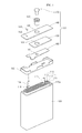
- FIGS. 1 , 2A , 2B , 3A and 3B a rechargeable battery according to an embodiment of the invention will be described with reference to FIGS. 1 , 2A , 2B , 3A and 3B .
- the rechargeable battery 100 includes an electrode assembly 110, a case 120 accommodating the electrode assembly 110, and a cap assembly 130 sealing a top opening 120a of the case 120.
- the electrode assembly 110 includes a first electrode plate 111, a second electrode plate 112 and a separator 113 that are wound roughly in a jelly roll configuration.
- the first electrode plate 111 and the second electrode plate 112 have different polarities.
- the first electrode plate 111 may be a positive electrode plate and the second electrode plate 112 may be a negative electrode plate, and vice versa.
- the electrode assembly 110 further includes a first electrode tab 114 and a second electrode tab 115 respectively welded to the first electrode plate 111 and the second electrode plate 112.
- the first electrode tab 114 has the same polarity as the first electrode plate 111 of the electrode assembly 110 and the second electrode tab 115 has the same polarity as the second electrode plate 112 of the electrode assembly 110.
- the following description will describe an embodiment wherein the first electrode tab 114 is a positive electrode tab and the second electrode tab 115 is a negative electrode tab.
- the first and second electrode tabs 114 and 115 protrude from a top portion of the electrode assembly 110.
- the electrode assembly 110 may further include an insulation tape 116 provided at a boundary portion from which the first and second electrode tabs 114 and 115 protrude to prevent electrode plates having different polarities from being electrically shorted.
- the case 120 may have a substantially hexahedral shape or another shape to accommodate the electrode assembly 110 in its internal space.
- the case 120 has a substantially hexahedral shape.
- the case 120 has the top opening 120a and the electrode assembly 110 is placed in the internal space of the case 120 through the top opening 120a.
- the case 120 is formed of a metal and may serve as a terminal.
- the case 120 may be formed of lightweight aluminum or an aluminum alloy.
- the cap assembly 130 includes a cap plate 140, an insulation plate 150, a terminal plate 160 and an electrode terminal 170.
- the cap assembly 130 is connected to a separate insulation case 180 that is connected to the top opening 120a of the case 120 to seal the case 120.
- the cap plate 140 may be a metal plate having a size and shape corresponding to the top opening 120a of the case 120.
- the first electrode tab 114 of the electrode assembly 110 passing through the insulation case 180 is welded to a bottom surface of the cap plate 140.
- the cap plate 140 has the same polarity as the first electrode tab 114 of the electrode assembly 110.
- a through hole or cap through hole 141 passing through between top and bottom surfaces of the cap plate 140 is formed in the center of the cap plate 140 and the electrode terminal 170 is inserted into the cap through hole 141.
- a tubular gasket 143 is mounted on an inner surface of the cap through hole 141. The gasket 143 is in close contact with the cap through hole 141 and the electrode terminal 170 between the cap through hole 141 and the electrode terminal 170 and electrically insulates the electrode terminal 170 and the cap plate 140 from each other. Accordingly, the cap through hole 141 of the cap plate 140 has a size corresponding to an outer diameter of the gasket 143.
- an electrolytic solution is injected into the internal space of the case 120 via an electrolyte injection hole 142 further provided at one side of the case 120.
- the electrolyte injection hole 142 is sealed by a plug 144.
- the insulation plate 150 is formed of an electrically insulating material and is arranged between the cap plate 140 and the terminal plate 160 to electrically insulate the cap plate 140 and the terminal plate 160 from each other.
- the insulation plate 150 includes a through hole or insulation through hole 151 located to correspond to the cap through hole 141 of the cap plate 140 to allow the electrode terminal 170 to be inserted into the through hole 151.
- the insulation plate 150 is connected to the electrode terminal 170 by inserting the electrode terminal 170 into the insulation through hole 151 of the insulation plate 150.
- the gasket 143 is further provided between the insulation through hole 151 of the insulation plate 150 and the electrode terminal 170.
- the insulation through hole 151 of the insulation plate 150 can have a size corresponding to the outer diameter of the gasket 143.
- the insulation through hole 151 of the insulation plate 150 can have a size corresponding to the cap through hole 141 of the cap plate 140.
- the terminal plate 160 may be a metal plate having a top surface 160a making close contact with a bottom surface of the insulation plate 150.
- a bottom surface 160b of the terminal plate 160 faces a top surface of the insulation case 180. Accordingly, the terminal plate 160 is interposed between the insulation plate 150 and the insulation case 180.
- the top surface 160a of the terminal plate 160 for example, has a smaller size than the bottom surface of the insulation plate 150.
- the terminal plate 160 is electrically insulated from the cap plate 140 by the insulation plate 150.
- the bottom surface 160b of the terminal plate 160 may be welded to the second electrode tab 115 of the electrode assembly 110 passing through the insulation case 180.
- the terminal plate 160 has a terminal through hole 161 passing through between the top surface 160a and the bottom surface 160b, and the electrode terminal 170 is inserted into the terminal through hole 161 to be electrically connected thereto.
- the terminal through hole 161 of the terminal plate 160 is located to correspond to the terminal through hole 141 of the cap plate 140.
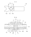
- a first inner diameter a of the terminal though hole 161 on the top surface 160a of the terminal plate 160 is less than a second inner diameter b of the bottom surface 160b of the terminal plate 160.
- the terminal through hole 161 on the top surface of the terminal plate 160 has a different shape and/or size from that on the bottom surface 160b of the terminal plate 160.
- the terminal through hole 161 includes a first terminal through hole 161a formed to extend from the top surface 160a to the bottom surface 160b of the terminal plate 160 and a second terminal through hole 161b formed to extend from the bottom surface 160b towards the top surface 160a of the terminal plate 160.
- central axes 161c of the first terminal through hole 161a and the second terminal through hole 161b are positioned on the same line, i.e. the first and second terminal through holes 161a and 161b are concentric.
- an inner diameter of the first terminal through hole 161a is substantially equal to the first inner diameter a on the top surface 160a of the terminal plate 160 and an inner diameter of the second terminal through hole 161b is substantially equal to the second inner diameter b on the bottom surface 160b of the terminal plate 160.
- the second inner diameter b of the second terminal through hole 161b is greater than the first inner diameter a of the first terminal through hole 161a.
- the terminal through hole 161 has at least one step formed due to the difference in the inner diameters between the first terminal through hole 161a and the second terminal through hole 161b.
- the terminal plate 160 further includes a protrusion part 162 horizontally protruding on the top surface 160a thereof toward the central axis 161c of the terminal through hole 161.
- the first inner diameter a of the first terminal through hole 161a is smaller than the second inner diameter b of the second terminal through hole 161b due to the protrusion part 162.
- the height of the first terminal through hole 161a may be greater than that of the second terminal through hole 161b.
- the terminal plate 160 may be configured such that the protrusion part 162 protrudes farther than an inner diameter of the gasket 143 toward the central axis 161c of the terminal through hole 161 to make the first inner diameter a of the first terminal through hole 161a less than the inner diameter of the gasket 143.
- the described technology is not limited thereto.
- the terminal plate 160 contacts the electrode terminal 170 such that it is in close contact with the first inner diameter a of the first terminal through hole 161a and a bottom surface 162a of the protrusion part 162.
- the terminal plate 160 is electrically connected to the electrode terminal 170.
- a region of the bottom surface 162a of the protrusion part 162, which is adjacent to the second inner diameter b of the terminal plate 160 may be exposed to a lower portion of the terminal plate 160.
- the second inner diameter b of the terminal plate 160 has a larger size than a cross-sectional area x of the bottom surface of the electrode terminal 170.
- the first terminal through hole 161a may have a substantially circular hole shape similar to the corresponding portion of the electrode terminal 170.
- the second terminal through hole 161b may have a substantially circular hole shape similar to the first terminal through hole 161a.
- the second terminal through hole 261b may have a substantially rectangular shape.
- the second terminal through hole 261b of a terminal plate 260 is substantially rectangular, but the described technology is not limited thereto.
- the second terminal through hole 261b of the terminal plate 260 may also have a substantially polygonal shape.
- a terminal plate 360 may further include a third terminal through hole 361c provided between a first terminal through hole 161a and a second terminal through hole 161b.
- the inner diameter of the third terminal through hole 361c may be greater than the first inner diameter a of the first terminal through hole 161a and may be less than the second inner diameter b of the second terminal through hole 161b. Accordingly, at least two steps may be formed between the first terminal through hole 161a and the second terminal through hole 161b due to the change in the inner diameter of the terminal through hole 361.
- the described technology is not limited to the above described number of steps in the terminal through hole 361.
- the electrode terminal 170 is inserted into the through holes 141,151 and 161 of the cap plate 140, the insulation plate 150 and the terminal plate 160.
- the electrode terminal 170 may be a metal pin having a substantially cylindrical shape.
- the electrode terminal 170 includes a body part 171 inserted in the through holes 141,151 and 161 and a head part 172 protruding a predetermined length to a top surface of the cap plate 140.
- the top surface of the cap plate 140 and the head part 172 of the electrode terminal 170 are electrically insulated from each other by the gasket 143.
- the gasket 143 is interposed between the body part 171 of the electrode terminal 170 and the cap plate 140 and between the body part 171 of the electrode terminal 170 and the insulation plate 150.
- the electrode terminal 170 is inserted into the terminal through hole 161 of the terminal plate 160 to contact the terminal plate 160.
- the electrode terminal 170 may be a negative terminal electrically connected to the terminal plate 160.
- the electrode terminal 170 is inserted into the through holes 141,151 and 161 of the cap plate 140, the insulation plate 150 and the terminal plate 160 while being rotated by spinning equipment.
- the electrode terminal 170 may have a lower portion outwardly spread from a central axis 161c.
- the terminal through hole 161 of the terminal plate 160 is configured to be stepped such that its bottom portion is larger than its top portion, thereby increasing the contact area between the terminal plate 160 and the electrode terminal 170 and reducing the contact resistance therebetween.
- the protrusion part 162 of the terminal plate 160 protrudes farther than an inner diameter of the gasket 143, the contact area between the terminal plate 160 and the electrode terminal 170 can be further increased.
- the insulation case 180 is formed of an electrically insulating material and is interposed between the cap assembly 130 and the electrode assembly 110 to electrically insulate the cap assembly 130 and the electrode assembly 110 from each other.
- the insulation case 180 includes tab holes 181 and 182 to allow the first electrode tab 114 and the second electrode tab 115 of the cap assembly 130 to protrude upward.
- the insulation case 180 electrically insulates the cap assembly 130 from a top end of the electrode assembly 110 from which the first electrode tab 114 and the second electrode tab 115 of the electrode assembly 110 protrude.
Landscapes
- Chemical & Material Sciences (AREA)
- Chemical Kinetics & Catalysis (AREA)
- Electrochemistry (AREA)
- General Chemical & Material Sciences (AREA)
- Engineering & Computer Science (AREA)
- Manufacturing & Machinery (AREA)
- Sealing Battery Cases Or Jackets (AREA)
- Connection Of Batteries Or Terminals (AREA)
- Secondary Cells (AREA)
Abstract
Description
- The invention generally relates to a rechargeable battery.
- Recently, compact and lightweight electrical/electronic devices such as cellular phones, notebook computers, and camcorders have been developed and manufactured. These devices typically employ a battery pack so that they can operate anywhere without reliance on a separate power source. Such battery packs include at least one battery incorporated therein to output a voltage of a predetermined level to drive portable electric/electronic devices for a given period of time. Battery packs generally use rechargeable secondary batteries due to the low cost of manufacturing these batteries.
- Rechargeable batteries often include an electrode assembly having a wound structure. The electrode assembly typically includes a positive electrode plate coated with a positive electrode active material, a negative electrode plate coated with a negative electrode active material and a separator interposed therebetween to prevent electric shorts. Rechargeable batteries also include a case accommodating the electrode assembly, an electrolytic solution injected into the case, and tend to have a cap assembly sealing the case. Such rechargeable batteries are manufactured by positioning the electrode assembly and the electrolytic solution into the case and sealing the case with the cap assembly.
- The cap assembly of such a rechargeable battery usually includes a cap plate including a through hole. The cap assembly typically also includes a terminal plate positioned under the cap plate and an insulation plate interposed between the cap plate and the terminal plate and electrically insulating the cap plate and the terminal plate from each other. The terminal plate and insulation plate both include through holes. The cap assembly also includes an electrode terminal connected to the through holes of the cap plate, the insulation plate and the terminal plate and electrically connected to the terminal plate.
- During manufacture, the electrode terminal is rotated and pressed by spinning equipment to be thermally deformed in the through holes of the cap plate, the insulation plate and the terminal plate to then be connected to the through holes. However, the electrode terminal may consequently have a tapered structure due to the rotation, resulting in an increase in contact resistance due to a reduced contact area between the electrode terminal and the terminal plate.
- The present invention sets out to overcome the above problems of the prior art.
- One inventive aspect is a rechargeable battery, which includes at least one step in a terminal through hole in a terminal plate by forming a bottom portion of the terminal through hole to be larger than a top portion of the terminal through hole, thereby stabilizing contact resistance between the terminal plate and electrode terminal by increasing a contact area therebetween.
- Another aspect is a rechargeable battery including rechargeable battery comprising an electrode assembly including a first electrode plate, a second electrode plate and a separator, a case in which the electrode assembly and an electrolytic solution are accommodated, and a cap assembly including a cap plate, an insulation plate, a terminal plate and an electrode terminal and coupled to a top opening of the case to seal the case, wherein the terminal plate includes a terminal through hole passing through between its top and surfaces to allow the electrode terminal to be inserted thereinto, and a cross-sectional area of the electrode terminal is larger than an inner diameter of the terminal through hole on the bottom surface of the terminal plate.
- An inner diameter of the terminal through hole on the bottom surface of the terminal plate may be larger than that of the terminal through hole on the top surface of the terminal through hole.
- The terminal through hole on the top surface of the terminal plate may have a different shape from that on the bottom surface of the terminal plate.
- The terminal plate may further include a protrusion part horizontally protruding on the top surface of the terminal plate toward the central axis of the terminal through hole.
- The terminal through hole may include a first terminal through hole formed to extend from the top surface to the bottom surface of the terminal plate and having a first inner diameter, and a second terminal through hole formed to extend from the bottom surface to the top surface of the terminal plate and having a second inner diameter larger than the first inner diameter of the first terminal through hole.
- At least one step may be provided between the first terminal through hole and the second terminal through hole.
- A central axis of the first terminal through hole and a central axis of the second terminal through hole may be positioned on the same line.
- A height of the first terminal through hole may be greater than that of the second terminal through hole.
- The terminal through hole may have a circular shape on the top surface of the terminal plate.
- The terminal through hole may be shaped of one of a circle and a polygon on the bottom surface of the terminal plate.
- The cap plate may include a terminal through hole passing through between its top and bottom surfaces to allow the electrode terminal to be inserted into the terminal through hole and may be electrically disconnected from the electrode terminal by a gasket surrounding an outer circumferential portion of the electrode terminal.
- The insulation plate may include a terminal through hole passing through between its top and bottom surfaces to allow the electrode terminal to be inserted into the terminal through hole and may be interposed between the cap plate and the terminal plate.
- Another aspect is a rechargeable battery including an electrode assembly including a first electrode plate, a second electrode plate and a separator, a case in which the electrode assembly and an electrolytic solution are accommodated, and a cap assembly including a cap plate, an insulation plate, a terminal plate and an electrode terminal and coupled to a top opening of the case to seal the case, wherein the terminal plate includes a terminal through hole passing through between its top and surfaces to allow the electrode terminal to be inserted thereinto, and the terminal plate includes at least one step provided in the terminal through hole between top and bottom surfaces of the terminal plate.
- An inner diameter of the terminal through hole on the bottom surface of the terminal plate may be larger than that of the terminal through hole on the top surface of the terminal through hole.
- Another aspect is a rechargeable battery comprising an electrode assembly including a first electrode plate, a second electrode plate and a separator; a case accommodating the electrode assembly, wherein the case has an opening; and a cap assembly including a cap plate, an insulation plate, a terminal plate and an electrode terminal, wherein the cap assembly substantially seals the opening of the case, wherein the terminal plate has a terminal through hole defined to pass through the terminal plate, wherein the terminal plate includes first and second surfaces opposing each other, wherein the first surface is closer to the electrode assembly than the second surface, wherein the electrode terminal includes first and second portions opposing each other, wherein the first portion is closer to the electrode assembly than the second portion, wherein at least the first portion of the electrode terminal is inserted into the terminal through hole, and wherein the diameter of the first portion of the electrode terminal is greater than a first diameter of the terminal through hole at the second surface of the terminal plate.
- The terminal through hole can have a second diameter at the first surface of the terminal plate and the second diameter can be greater than the first diameter. The terminal through hole can have different shapes at the first and second opposing surfaces of the terminal plate. The terminal plate can further include a protrusion part protruding toward the central axis of the terminal through hole. A recess can be formed adjacent to the first portion of the electrode terminal and at least a portion of the protrusion part can be inserted into the recess. The terminal through hole can include a first terminal through hole having the first diameter and downwardly extending from the second surface of the terminal plate and a second terminal through hole having a second diameter greater than the first diameter and upwardly extending from the first surface of the terminal plate.
- At least one axially aligned step can be formed between the first and second terminal through holes. The first and second terminal through holes can be concentric. The height of the first terminal through hole can be greater than that of the second terminal through hole. The terminal through hole can have a substantially circular shape on the second surface of the terminal plate. The terminal through hole can have a substantially circular or polygonal shape on the first surface of the terminal plate. The cap plate can have a cap through hole defined to pass through the cap plate, wherein at least the first portion of the electrode terminal is inserted into the cap through hole and wherein the rechargeable battery further comprises a gasket electrically insulating the cap plate from the electrode terminal. The insulation plate can have an insulation through hole defined to pass through the insulation plate, wherein at least the first portion of the electrode terminal is inserted into the insulation through hole and wherein the insulation plate is interposed between the cap plate and the terminal plate.
- Another aspect is a rechargeable battery comprising an electrode assembly including a first electrode plate, a second electrode plate and a separator; a case accommodating the electrode assembly, wherein the case has an opening; and a cap assembly including a cap plate, an insulation plate, a terminal plate and an electrode terminal, wherein the cap assembly substantially seals the opening of the case, wherein the terminal plate has a terminal through hole defined to pass through the terminal plate, wherein at least a portion of the electrode terminal is inserted into the terminal through hole, and wherein at least one step is formed in the terminal through hole between opposing surfaces of the terminal plate.
- The terminal plate can include first and second surfaces opposing each other, wherein the first surface is closer to the electrode assembly than the second surface, wherein the terminal through hole has a first diameter at the second surface of the terminal plate and a second diameter at the first surface of the terminal plate, and wherein the second diameter is greater than the first diameter.
- Another aspect is a rechargeable battery comprising an electrode assembly; a case accommodating the electrode assembly; a cap assembly substantially sealing the case, wherein the cap assembly includes a terminal plate having top and bottom surfaces with a stepped terminal through hole extending from the top surface to the bottom surface; and an electrode terminal extending through the terminal through hole of the terminal plate, wherein the electrode terminal has a bottom portion that is larger than a minimum diameter of the terminal through hole.
- The bottom surface of the terminal plate can include a recess that receives the bottom portion of the electrode terminal. The recess in the bottom portion of the electrode terminal can have a cross sectional area that is greater than the cross sectional area of the through hole at the top surface of the terminal plate. The shape of the terminal through hole at the top surface of the terminal plate can be different than the shape of the recess at the bottom surface of the terminal plate. The recess can form at least one step at the bottom surface of the terminal plate.
- At least some of the above and other features of the invention are set out in the claims.
- Additional aspects and/or advantages will be set forth in part in the description which follows and in part will be obvious from the description or may be learned by practice of the described technology.
-
-
FIG. 1 is an exploded perspective view illustrating a rechargeable battery according to an embodiment of the invention. -
FIGS. 2A and 2B are a bottom view and a partially cross-sectional view of the cap assembly of the rechargeable battery shown inFIG. 1 . -
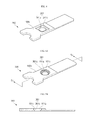
FIGS. 3A and 3B are a bottom perspective view and a cross-sectional view of the cap plate of the rechargeable battery shown inFIG. 1 . -
FIG. 4 is a bottom perspective view illustrating the cap plate of a rechargeable battery according to another embodiment of the invention. -
FIGS. 5A and 5B are a bottom perspective view and a cross-sectional view of the cap plate of the rechargeable battery shown inFIG. 4 . - Hereinafter, examples of embodiments of the invention will be described in detail with reference to the accompanying drawings such that they can easily be made and used by those skilled in the art. Throughout the specification, like numerals refer to like elements.
- Hereinafter, a rechargeable battery according to an embodiment of the invention will be described with reference to
FIGS. 1 ,2A ,2B ,3A and 3B . - The rechargeable battery 100 includes an
electrode assembly 110, acase 120 accommodating theelectrode assembly 110, and acap assembly 130 sealing atop opening 120a of thecase 120. - In some embodiments, the
electrode assembly 110 includes afirst electrode plate 111, asecond electrode plate 112 and aseparator 113 that are wound roughly in a jelly roll configuration. Thefirst electrode plate 111 and thesecond electrode plate 112 have different polarities. Thefirst electrode plate 111 may be a positive electrode plate and thesecond electrode plate 112 may be a negative electrode plate, and vice versa. - The
electrode assembly 110 further includes afirst electrode tab 114 and asecond electrode tab 115 respectively welded to thefirst electrode plate 111 and thesecond electrode plate 112. Thus, thefirst electrode tab 114 has the same polarity as thefirst electrode plate 111 of theelectrode assembly 110 and thesecond electrode tab 115 has the same polarity as thesecond electrode plate 112 of theelectrode assembly 110. The following description will describe an embodiment wherein thefirst electrode tab 114 is a positive electrode tab and thesecond electrode tab 115 is a negative electrode tab. The first andsecond electrode tabs electrode assembly 110. In addition, theelectrode assembly 110 may further include aninsulation tape 116 provided at a boundary portion from which the first andsecond electrode tabs - The
case 120 may have a substantially hexahedral shape or another shape to accommodate theelectrode assembly 110 in its internal space. In this embodiment, thecase 120 has a substantially hexahedral shape. Thecase 120 has thetop opening 120a and theelectrode assembly 110 is placed in the internal space of thecase 120 through thetop opening 120a. Thecase 120 is formed of a metal and may serve as a terminal. Thecase 120 may be formed of lightweight aluminum or an aluminum alloy. - The
cap assembly 130 includes acap plate 140, aninsulation plate 150, aterminal plate 160 and anelectrode terminal 170. Thecap assembly 130 is connected to aseparate insulation case 180 that is connected to thetop opening 120a of thecase 120 to seal thecase 120. - The
cap plate 140 may be a metal plate having a size and shape corresponding to thetop opening 120a of thecase 120. Thefirst electrode tab 114 of theelectrode assembly 110 passing through theinsulation case 180 is welded to a bottom surface of thecap plate 140. Thus, thecap plate 140 has the same polarity as thefirst electrode tab 114 of theelectrode assembly 110. - A through hole or cap through
hole 141 passing through between top and bottom surfaces of thecap plate 140 is formed in the center of thecap plate 140 and theelectrode terminal 170 is inserted into the cap throughhole 141. In order to insulate theelectrode terminal 170 and thecap plate 140 from each other, atubular gasket 143 is mounted on an inner surface of the cap throughhole 141. Thegasket 143 is in close contact with the cap throughhole 141 and theelectrode terminal 170 between the cap throughhole 141 and theelectrode terminal 170 and electrically insulates theelectrode terminal 170 and thecap plate 140 from each other. Accordingly, the cap throughhole 141 of thecap plate 140 has a size corresponding to an outer diameter of thegasket 143. - After the
cap plate 140 is assembled with thetop opening 120a of thecase 120, an electrolytic solution is injected into the internal space of thecase 120 via anelectrolyte injection hole 142 further provided at one side of thecase 120. In addition, after the electrolytic solution is injected into thecase 120, theelectrolyte injection hole 142 is sealed by aplug 144. - The
insulation plate 150 is formed of an electrically insulating material and is arranged between thecap plate 140 and theterminal plate 160 to electrically insulate thecap plate 140 and theterminal plate 160 from each other. Theinsulation plate 150 includes a through hole or insulation throughhole 151 located to correspond to the cap throughhole 141 of thecap plate 140 to allow theelectrode terminal 170 to be inserted into the throughhole 151. Theinsulation plate 150 is connected to theelectrode terminal 170 by inserting theelectrode terminal 170 into the insulation throughhole 151 of theinsulation plate 150. Thegasket 143 is further provided between the insulation throughhole 151 of theinsulation plate 150 and theelectrode terminal 170. In addition, the insulation throughhole 151 of theinsulation plate 150 can have a size corresponding to the outer diameter of thegasket 143. Thus, the insulation throughhole 151 of theinsulation plate 150 can have a size corresponding to the cap throughhole 141 of thecap plate 140. - The
terminal plate 160 may be a metal plate having atop surface 160a making close contact with a bottom surface of theinsulation plate 150. Abottom surface 160b of theterminal plate 160 faces a top surface of theinsulation case 180. Accordingly, theterminal plate 160 is interposed between theinsulation plate 150 and theinsulation case 180. Thetop surface 160a of theterminal plate 160, for example, has a smaller size than the bottom surface of theinsulation plate 150. Theterminal plate 160 is electrically insulated from thecap plate 140 by theinsulation plate 150. Thebottom surface 160b of theterminal plate 160 may be welded to thesecond electrode tab 115 of theelectrode assembly 110 passing through theinsulation case 180. - The
terminal plate 160 has a terminal throughhole 161 passing through between thetop surface 160a and thebottom surface 160b, and theelectrode terminal 170 is inserted into the terminal throughhole 161 to be electrically connected thereto. The terminal throughhole 161 of theterminal plate 160 is located to correspond to the terminal throughhole 141 of thecap plate 140. - A first inner diameter a of the terminal though
hole 161 on thetop surface 160a of theterminal plate 160 is less than a second inner diameter b of thebottom surface 160b of theterminal plate 160. The terminal throughhole 161 on the top surface of theterminal plate 160 has a different shape and/or size from that on thebottom surface 160b of theterminal plate 160. - The terminal through
hole 161 includes a first terminal throughhole 161a formed to extend from thetop surface 160a to thebottom surface 160b of theterminal plate 160 and a second terminal throughhole 161b formed to extend from thebottom surface 160b towards thetop surface 160a of theterminal plate 160. Here,central axes 161c of the first terminal throughhole 161a and the second terminal throughhole 161b are positioned on the same line, i.e. the first and second terminal throughholes hole 161a is substantially equal to the first inner diameter a on thetop surface 160a of theterminal plate 160 and an inner diameter of the second terminal throughhole 161b is substantially equal to the second inner diameter b on thebottom surface 160b of theterminal plate 160. Thus, the second inner diameter b of the second terminal throughhole 161b is greater than the first inner diameter a of the first terminal throughhole 161a. The terminal throughhole 161 has at least one step formed due to the difference in the inner diameters between the first terminal throughhole 161a and the second terminal throughhole 161b. - The
terminal plate 160 further includes aprotrusion part 162 horizontally protruding on thetop surface 160a thereof toward thecentral axis 161c of the terminal throughhole 161. The first inner diameter a of the first terminal throughhole 161a is smaller than the second inner diameter b of the second terminal throughhole 161b due to theprotrusion part 162. Here, the height of the first terminal throughhole 161a may be greater than that of the second terminal throughhole 161b. In addition, theterminal plate 160 may be configured such that theprotrusion part 162 protrudes farther than an inner diameter of thegasket 143 toward thecentral axis 161c of the terminal throughhole 161 to make the first inner diameter a of the first terminal throughhole 161a less than the inner diameter of thegasket 143. However, the described technology is not limited thereto. - The
terminal plate 160 contacts theelectrode terminal 170 such that it is in close contact with the first inner diameter a of the first terminal throughhole 161a and abottom surface 162a of theprotrusion part 162. Theterminal plate 160 is electrically connected to theelectrode terminal 170. Here, a region of thebottom surface 162a of theprotrusion part 162, which is adjacent to the second inner diameter b of theterminal plate 160, may be exposed to a lower portion of theterminal plate 160. Accordingly, the second inner diameter b of theterminal plate 160 has a larger size than a cross-sectional area x of the bottom surface of theelectrode terminal 170. - In order to make the first terminal through
hole 161a contact an outer circumferential surface of theelectrode terminal 170, the first terminal throughhole 161a may have a substantially circular hole shape similar to the corresponding portion of theelectrode terminal 170. The second terminal throughhole 161b may have a substantially circular hole shape similar to the first terminal throughhole 161a. However, as shown inFIG. 4 , the second terminal throughhole 261b may have a substantially rectangular shape. InFIG. 4 , the second terminal throughhole 261b of aterminal plate 260 is substantially rectangular, but the described technology is not limited thereto. The second terminal throughhole 261b of theterminal plate 260 may also have a substantially polygonal shape. - In addition, as shown in
FIGS. 5A and 5B , aterminal plate 360 may further include a third terminal throughhole 361c provided between a first terminal throughhole 161a and a second terminal throughhole 161b. The inner diameter of the third terminal throughhole 361c may be greater than the first inner diameter a of the first terminal throughhole 161a and may be less than the second inner diameter b of the second terminal throughhole 161b. Accordingly, at least two steps may be formed between the first terminal throughhole 161a and the second terminal throughhole 161b due to the change in the inner diameter of the terminal throughhole 361. However, the described technology is not limited to the above described number of steps in the terminal throughhole 361. - The
electrode terminal 170 is inserted into the through holes 141,151 and 161 of thecap plate 140, theinsulation plate 150 and theterminal plate 160. Theelectrode terminal 170 may be a metal pin having a substantially cylindrical shape. Theelectrode terminal 170 includes abody part 171 inserted in the through holes 141,151 and 161 and ahead part 172 protruding a predetermined length to a top surface of thecap plate 140. The top surface of thecap plate 140 and thehead part 172 of theelectrode terminal 170 are electrically insulated from each other by thegasket 143. - In addition, the
gasket 143 is interposed between thebody part 171 of theelectrode terminal 170 and thecap plate 140 and between thebody part 171 of theelectrode terminal 170 and theinsulation plate 150. Theelectrode terminal 170 is inserted into the terminal throughhole 161 of theterminal plate 160 to contact theterminal plate 160. Theelectrode terminal 170 may be a negative terminal electrically connected to theterminal plate 160. - The
electrode terminal 170 is inserted into the through holes 141,151 and 161 of thecap plate 140, theinsulation plate 150 and theterminal plate 160 while being rotated by spinning equipment. Here, theelectrode terminal 170 may have a lower portion outwardly spread from acentral axis 161c. The terminal throughhole 161 of theterminal plate 160 is configured to be stepped such that its bottom portion is larger than its top portion, thereby increasing the contact area between theterminal plate 160 and theelectrode terminal 170 and reducing the contact resistance therebetween. When theprotrusion part 162 of theterminal plate 160 protrudes farther than an inner diameter of thegasket 143, the contact area between theterminal plate 160 and theelectrode terminal 170 can be further increased. - The
insulation case 180 is formed of an electrically insulating material and is interposed between thecap assembly 130 and theelectrode assembly 110 to electrically insulate thecap assembly 130 and theelectrode assembly 110 from each other. In addition, theinsulation case 180 includes tab holes 181 and 182 to allow thefirst electrode tab 114 and thesecond electrode tab 115 of thecap assembly 130 to protrude upward. Thus, theinsulation case 180 electrically insulates thecap assembly 130 from a top end of theelectrode assembly 110 from which thefirst electrode tab 114 and thesecond electrode tab 115 of theelectrode assembly 110 protrude. - Although the inventive technology has been described with reference to certain exemplary embodiments thereof, it will be understood by those skilled in the art that a variety of modifications and variations may be made to the present invention without departing from the spirit or scope of the present invention defined in the appended claims, and their equivalents.
Claims (15)
- A rechargeable battery, comprising:an electrode assembly including a first electrode plate, a second electrode plate and a separator;a case accommodating the electrode assembly, wherein the case has an opening; anda cap assembly including a cap plate, an insulation plate, a terminal plate and an electrode terminal, wherein the cap assembly substantially seals the opening of the case, wherein the terminal plate has a terminal through hole defined to pass through the terminal plate, wherein the terminal plate includes first and second surfaces opposing each other, wherein the first surface is closer to the electrode assembly than the second surface, wherein the electrode terminal includes first and second portions opposing each other, wherein the first portion is closer to the electrode assembly than the second portion, wherein at least the first portion of the electrode terminal is inserted into the terminal through hole, and wherein the diameter of the first portion of the electrode terminal is greater than a first diameter of the terminal through hole at the second surface of the terminal plate.
- A rechargeable battery according to claim 1, wherein the terminal through hole has a second diameter at the first surface of the terminal plate and wherein the second diameter is greater than the first diameter.
- A rechargeable battery according to claim 1 or 2, wherein the terminal through hole has different shapes at the first and second opposing surfaces of the terminal plate.
- A rechargeable battery according to any preceding claim, wherein the terminal plate further includes a protrusion part protruding toward the central axis of the terminal through hole.
- A rechargeable battery according to claim 4, wherein a recess is formed adjacent to the first portion of the electrode terminal and wherein at least a portion of the protrusion part is inserted into the recess.
- A rechargeable battery according to claim 1, wherein the terminal through hole includes:a first terminal through hole having the first diameter and downwardly extending from the second surface of the terminal plate; anda second terminal through hole having a second diameter greater than the first diameter and upwardly extending from the first surface of the terminal plate.
- A rechargeable battery according to claim 6, wherein at least one axially aligned step is formed between the first and second terminal through holes.
- A rechargeable battery according to claim 6 or 7, wherein the first and second terminal through holes are concentric.
- A rechargeable battery according to claim 6, 7 or 8, wherein the height of the first terminal through hole is greater than that of the second terminal through hole.
- A rechargeable battery according to any preceding claim, wherein the terminal through hole has a substantially circular shape on the second surface of the terminal plate.
- A rechargeable battery according to any preceding claim, wherein the terminal through hole has a substantially circular or polygonal shape on the first surface of the terminal plate.
- A rechargeable battery comprising:an electrode assembly including a first electrode plate, a second electrode plate and a separator;a case accommodating the electrode assembly, wherein the case has an opening; anda cap assembly including a cap plate, an insulation plate, a terminal plate and an electrode terminal, wherein the cap assembly substantially seals the opening of the case, wherein the terminal plate has a terminal through hole defined to pass through the terminal plate, wherein at least a portion of the electrode terminal is inserted into the terminal through hole, wherein at least one step is formed in the terminal through hole between opposing surfaces of the terminal plate, wherein the terminal plate includes first and second surfaces opposing each other, wherein the first surface is closer to the electrode assembly than the second surface, wherein the terminal through hole has a first diameter at the second surface of the terminal plate and a second diameter at the first surface of the terminal plate, and wherein the second diameter is greater than the first diameter.
- A rechargeable battery comprising:an electrode assembly;a case accommodating the electrode assembly;a cap assembly substantially sealing the case, wherein the cap assembly includes a terminal plate having top and bottom surfaces with a stepped terminal through hole extending from the top surface to the bottom surface; andan electrode terminal extending through the terminal through hole of the terminal plate,wherein the electrode terminal has a bottom portion that is larger than a minimum diameter of the terminal through hole.
- A battery according to claim 13, wherein the bottom surface of the terminal plate includes a recess that receives the bottom portion of the electrode terminal.
- A battery according to claim 14, wherein the recess forms at least one step at the bottom surface of the terminal plate.
Applications Claiming Priority (1)
| Application Number | Priority Date | Filing Date | Title |
|---|---|---|---|
| KR1020140023696A KR20150101863A (en) | 2014-02-27 | 2014-02-27 | Rechargeable battery |
Publications (2)
| Publication Number | Publication Date |
|---|---|
| EP2924767A2 true EP2924767A2 (en) | 2015-09-30 |
| EP2924767A3 EP2924767A3 (en) | 2015-11-18 |
Family
ID=52133980
Family Applications (1)
| Application Number | Title | Priority Date | Filing Date |
|---|---|---|---|
| EP14199055.6A Withdrawn EP2924767A3 (en) | 2014-02-27 | 2014-12-18 | Rechargeable battery |
Country Status (5)
| Country | Link |
|---|---|
| US (1) | US20150243940A1 (en) |
| EP (1) | EP2924767A3 (en) |
| JP (1) | JP2015162458A (en) |
| KR (1) | KR20150101863A (en) |
| CN (1) | CN104882572A (en) |
Families Citing this family (13)
| Publication number | Priority date | Publication date | Assignee | Title |
|---|---|---|---|---|
| KR20150101864A (en) * | 2014-02-27 | 2015-09-04 | 삼성에스디아이 주식회사 | Secondary battery |
| KR101724910B1 (en) * | 2015-09-24 | 2017-04-07 | 현대자동차주식회사 | Fuel cell stack having multi-layer type current collector plate |
| KR102496391B1 (en) * | 2015-11-11 | 2023-02-06 | 삼성에스디아이 주식회사 | Secondary Battery |
| JP6731176B2 (en) * | 2016-01-21 | 2020-07-29 | 株式会社Gsユアサ | Electric storage element and method for manufacturing electric storage element |
| KR102611656B1 (en) * | 2016-08-30 | 2023-12-08 | 삼성에스디아이 주식회사 | Secondary battery |
| KR102909245B1 (en) * | 2019-12-13 | 2026-01-06 | 삼성에스디아이 주식회사 | Rechargeable battery |
| KR102927441B1 (en) * | 2020-06-23 | 2026-02-12 | 삼성에스디아이 주식회사 | Secondary battery |
| KR102885284B1 (en) * | 2020-07-01 | 2025-11-11 | 삼성에스디아이 주식회사 | Rechargeable battery |
| WO2022010249A1 (en) * | 2020-07-10 | 2022-01-13 | 삼성에스디아이 주식회사 | Rechargeable battery |
| US20220021055A1 (en) * | 2020-07-15 | 2022-01-20 | Samsung Sdi Co., Ltd. | Rechargeable battery |
| SE546405C2 (en) * | 2021-06-04 | 2024-10-29 | Northvolt Ab | A cylindrical secondary cell with shaped can hole wall and a method of its assembly |
| EP4475295A4 (en) * | 2022-05-16 | 2025-04-02 | Contemporary Amperex Technology (Hong Kong) Limited | END COVER, ELEMENT, BATTERY AND ELECTRICAL DEVICE ASSEMBLY |
| JP7677310B2 (en) | 2022-11-11 | 2025-05-15 | トヨタ自動車株式会社 | Energy storage cell |
Family Cites Families (5)
| Publication number | Priority date | Publication date | Assignee | Title |
|---|---|---|---|---|
| US7993777B2 (en) * | 2004-11-29 | 2011-08-09 | Samsung Sdi Co., Ltd. | Lithium secondary battery |
| US8765291B2 (en) * | 2009-05-20 | 2014-07-01 | Samsung Sdi Co., Ltd. | Rechargeable battery |
| KR101657332B1 (en) * | 2012-06-15 | 2016-09-13 | 삼성에스디아이 주식회사 | Rechargeable battery |
| KR20140096815A (en) * | 2013-01-29 | 2014-08-06 | 삼성에스디아이 주식회사 | Rechargeable battery |
| KR102154332B1 (en) * | 2014-02-27 | 2020-09-09 | 삼성에스디아이 주식회사 | Secondary Battery |
-
2014
- 2014-02-27 KR KR1020140023696A patent/KR20150101863A/en not_active Withdrawn
- 2014-05-07 JP JP2014095968A patent/JP2015162458A/en active Pending
- 2014-11-19 US US14/547,985 patent/US20150243940A1/en not_active Abandoned
- 2014-12-18 EP EP14199055.6A patent/EP2924767A3/en not_active Withdrawn
-
2015
- 2015-01-12 CN CN201510014651.0A patent/CN104882572A/en active Pending
Non-Patent Citations (1)
| Title |
|---|
| None |
Also Published As
| Publication number | Publication date |
|---|---|
| JP2015162458A (en) | 2015-09-07 |
| EP2924767A3 (en) | 2015-11-18 |
| KR20150101863A (en) | 2015-09-04 |
| US20150243940A1 (en) | 2015-08-27 |
| CN104882572A (en) | 2015-09-02 |
Similar Documents
| Publication | Publication Date | Title |
|---|---|---|
| EP2924767A2 (en) | Rechargeable battery | |
| CN104882626B (en) | Secondary battery | |
| US10665827B2 (en) | Cap assembly for a second battery and second battery | |
| US9136524B2 (en) | Secondary battery | |
| KR102246736B1 (en) | Rechargeable battery | |
| KR101683213B1 (en) | Rechargeable battery | |
| EP3082178B1 (en) | Rechargeable battery | |
| KR101679413B1 (en) | Hollow-shaped rechargeable battery | |
| KR102108277B1 (en) | Rechargeable battery | |
| US9853281B2 (en) | Secondary battery | |
| KR20150112879A (en) | Electrochemical energy storage device with flexible metal contact current collector and methods of manufacture | |
| KR100696785B1 (en) | Cylindrical lithium secondary battery | |
| KR20170017520A (en) | A secondary battery | |
| JP2004349241A (en) | Rechargeable battery | |
| JP2009094045A (en) | Secondary battery and battery module | |
| US9559341B2 (en) | Rechargeable battery having a vent unit at a joint in a cap plate | |
| US20100086847A1 (en) | Secondary battery | |
| KR20160106429A (en) | Rechargeable battery | |
| KR20160100673A (en) | Battery pack | |
| US10651454B2 (en) | Rechargeable battery | |
| KR20160036912A (en) | Rechargeable batter00y | |
| CN100466360C (en) | Rechargeable cylindrical lithium battery | |
| KR100670453B1 (en) | Cylindrical lithium secondary battery | |
| KR20070081559A (en) | Battery-free battery pack using interference fit rivets | |
| US10374208B2 (en) | Rechargeable battery |
Legal Events
| Date | Code | Title | Description |
|---|---|---|---|
| PUAI | Public reference made under article 153(3) epc to a published international application that has entered the european phase |
Free format text: ORIGINAL CODE: 0009012 |
|
| AK | Designated contracting states |
Kind code of ref document: A2 Designated state(s): AL AT BE BG CH CY CZ DE DK EE ES FI FR GB GR HR HU IE IS IT LI LT LU LV MC MK MT NL NO PL PT RO RS SE SI SK SM TR |
|
| AX | Request for extension of the european patent |
Extension state: BA ME |
|
| PUAL | Search report despatched |
Free format text: ORIGINAL CODE: 0009013 |
|
| AK | Designated contracting states |
Kind code of ref document: A3 Designated state(s): AL AT BE BG CH CY CZ DE DK EE ES FI FR GB GR HR HU IE IS IT LI LT LU LV MC MK MT NL NO PL PT RO RS SE SI SK SM TR |
|
| AX | Request for extension of the european patent |
Extension state: BA ME |
|
| RIC1 | Information provided on ipc code assigned before grant |
Ipc: H01M 2/22 20060101AFI20151009BHEP Ipc: H01M 2/30 20060101ALI20151009BHEP |
|
| 17P | Request for examination filed |
Effective date: 20160518 |
|
| RBV | Designated contracting states (corrected) |
Designated state(s): AL AT BE BG CH CY CZ DE DK EE ES FI FR GB GR HR HU IE IS IT LI LT LU LV MC MK MT NL NO PL PT RO RS SE SI SK SM TR |
|
| STAA | Information on the status of an ep patent application or granted ep patent |
Free format text: STATUS: THE APPLICATION IS DEEMED TO BE WITHDRAWN |
|
| 18D | Application deemed to be withdrawn |
Effective date: 20160519 |