EP2924572A2 - Réseaux de chaudière analytique au niveau d'un nuage virtuel - Google Patents
Réseaux de chaudière analytique au niveau d'un nuage virtuel Download PDFInfo
- Publication number
- EP2924572A2 EP2924572A2 EP15160980.7A EP15160980A EP2924572A2 EP 2924572 A2 EP2924572 A2 EP 2924572A2 EP 15160980 A EP15160980 A EP 15160980A EP 2924572 A2 EP2924572 A2 EP 2924572A2
- Authority
- EP
- European Patent Office
- Prior art keywords
- data
- boiler
- cloud
- boilers
- industrial
- Prior art date
- Legal status (The legal status is an assumption and is not a legal conclusion. Google has not performed a legal analysis and makes no representation as to the accuracy of the status listed.)
- Granted
Links
Images


Classifications
-
- F—MECHANICAL ENGINEERING; LIGHTING; HEATING; WEAPONS; BLASTING
- F22—STEAM GENERATION
- F22B—METHODS OF STEAM GENERATION; STEAM BOILERS
- F22B35/00—Control systems for steam boilers
- F22B35/18—Applications of computers to steam boiler control
-
- G—PHYSICS
- G06—COMPUTING; CALCULATING OR COUNTING
- G06F—ELECTRIC DIGITAL DATA PROCESSING
- G06F9/00—Arrangements for program control, e.g. control units
- G06F9/06—Arrangements for program control, e.g. control units using stored programs, i.e. using an internal store of processing equipment to receive or retain programs
- G06F9/46—Multiprogramming arrangements
- G06F9/50—Allocation of resources, e.g. of the central processing unit [CPU]
- G06F9/5061—Partitioning or combining of resources
- G06F9/5072—Grid computing
-
- G—PHYSICS
- G05—CONTROLLING; REGULATING
- G05B—CONTROL OR REGULATING SYSTEMS IN GENERAL; FUNCTIONAL ELEMENTS OF SUCH SYSTEMS; MONITORING OR TESTING ARRANGEMENTS FOR SUCH SYSTEMS OR ELEMENTS
- G05B13/00—Adaptive control systems, i.e. systems automatically adjusting themselves to have a performance which is optimum according to some preassigned criterion
- G05B13/02—Adaptive control systems, i.e. systems automatically adjusting themselves to have a performance which is optimum according to some preassigned criterion electric
- G05B13/04—Adaptive control systems, i.e. systems automatically adjusting themselves to have a performance which is optimum according to some preassigned criterion electric involving the use of models or simulators
Definitions
- the subject matter disclosed herein relates generally to industrial control systems, and, more particularly, to a cloud-based boiler control system that generates recommended set point parameters based on collection and analysis of data from an industrial boiler system.
- a system in one or more embodiments, includes a system interface component, a modeling component and a correlation analytics component.
- the system interface component collects industrial data associated with a set of boilers and demand data associated with a set of loads.
- the system interface component also stores the industrial data and the demand data on a cloud platform.
- the modeling component generates a boiler behavioral model for storage on the cloud platform based on analysis of the industrial data and the demand data.
- the boiler behavioral model defines at least one correlation between efficiency and capacity associated with the set of boilers.
- the correlation analytics component determines at least one set point parameter for the set of boilers based on analysis of the boiler behavioral model.
- one or more embodiments provide a method for receiving, at a cloud platform by a system comprising at least one processor, industrial data from one or more boilers of an industrial boiler system and demand data from one or more loads of the industrial boiler system.
- the method also includes creating, by the system, a boiler behavioral model based on analysis of the industrial data and the demand data including storing the boiler behavioral model on cloud storage of the cloud platform, wherein the boiler behavioral model encodes at least one correlation between efficiency and capacity associated with the one or more boilers.
- the method includes determining, by the system, at least one set point parameter for the one or more boilers based on an analysis of the boiler behavioral model..
- a non-transitory computer-readable medium having stored thereon instructions that, in response to execution, cause a system to perform operations, the operations, comprising receiving, via a cloud platform, industrial data from one or more boilers of an industrial boiler system and demand data from one or more loads of the industrial boiler system.
- the operations also comprise generating a boiler behavioral model based on analysis of the industrial data and the demand data, wherein the boiler behavioral model defines at least one correlation between efficiency and capacity associated with the one or more boilers.
- the operations comprise storing the boiler behavioral model on cloud storage of the cloud platform.
- the operations comprise generating at least one set point parameter for the one or more boilers based on an analysis of the boiler behavioral model.
- the terms "component,” “system,” “platform,” “layer,” “controller,” “terminal,” “station,” “node,” “interface” are intended to refer to a computer-related entity or an entity related to, or that is part of, an operational apparatus with one or more specific functionalities, wherein such entities can be either hardware, a combination of hardware and software, software, or software in execution.
- a component can be, but is not limited to being, a process running on a processor, a processor, a hard disk drive, multiple storage drives (of optical or magnetic storage medium) including affixed (e.g., screwed or bolted) or removable affixed solid-state storage drives; an object; an executable; a thread of execution; a computer-executable program, and/or a computer.
- affixed e.g., screwed or bolted
- the components may communicate via local and/or remote processes such as in accordance with a signal having one or more data packets (e.g., data from one component interacting with another component in a local system, distributed system, and/or across a network such as the Internet with other systems via the signal).
- a component can be an apparatus with specific functionality provided by mechanical parts operated by electric or electronic circuitry which is operated by a software or a firmware application executed by a processor, wherein the processor can be internal or external to the apparatus and executes at least a part of the software or firmware application.
- a component can be an apparatus that provides specific functionality through electronic components without mechanical parts, the electronic components can include a processor therein to execute software or firmware that provides at least in part the functionality of the electronic components.
- interface(s) can include input/output (I/O) components as well as associated processor, application, or Application Programming Interface (API) components. While the foregoing examples are directed to aspects of a component, the exemplified aspects or features also apply to a system, platform, interface, layer, controller, terminal, and the like.
- I/O input/output
- API Application Programming Interface
- the terms "to infer” and “inference” refer generally to the process of reasoning about or inferring states of the system, environment, and/or user from a set of observations as captured via events and/or data. Inference can be employed to identify a specific context or action, or can generate a probability distribution over states, for example. The inference can be probabilistic-that is, the computation of a probability distribution over states of interest based on a consideration of data and events. Inference can also refer to techniques employed for composing higher-level events from a set of events and/or data. Such inference results in the construction of new events or actions from a set of observed events and/or stored event data, whether or not the events are correlated in close temporal proximity, and whether the events and data come from one or several event and data sources.
- the term "or” is intended to mean an inclusive “or” rather than an exclusive “or.” That is, unless specified otherwise, or clear from the context, the phrase “X employs A or B” is intended to mean any of the natural inclusive permutations. That is, the phrase “X employs A or B” is satisfied by any of the following instances: X employs A; X employs B; or X employs both A and B.
- the articles “a” and “an” as used in this application and the appended claims should generally be construed to mean “one or more” unless specified otherwise or clear from the context to be directed to a singular form.
- a “set” in the subject disclosure includes one or more elements or entities.
- a set of controllers includes one or more controllers; a set of data resources includes one or more data resources; etc.
- group refers to a collection of one or more entities; e.g., a group of nodes refers to one or more nodes.
- Industrial controllers and their associated I/O devices are central to the operation of modern automation systems. These controllers interact with field devices on the plant floor to control automated processes relating to such objectives as product manufacture, material handling, batch processing, supervisory control, and other such applications. Industrial controllers store and execute user-defined control programs to effect decision-making in connection with the controlled process. Such programs can include, but are not limited to, ladder logic, sequential function charts, function block diagrams, structured text, or other such programming structures.
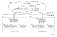
- FIG. 1 illustrates an example system 100 associated with a simplified boiler control architecture.
- System 100 can include boilers 102a-n.
- the boilers 102an can be configured to heat water or another type of fluid.
- the boilers 102a-n can provide output to the loads 104a-n.
- the loads 104a-n can include, but are not limited to, one or more heating loads, one or more process loads and/or one or more combination loads.
- the boilers 102a-n can provide steam (e.g., STEAM shown in FIG. 1 ) to the loads 104a-n (e.g., via a steam header, a pipeline, etc.).
- steam provided to the loads 104a-n by the boilers 102a-n can be low pressure steam.
- steam provided to the loads 104a-n by the boilers 102a-n can be high pressure steam.
- the boilers 102a-n can provide different output to the loads 104a-n.
- the boilers 102a-n can each receive a heat source (e.g., HEAT SOURCE shown in FIG. 1 ).
- the heat source can be fuel to heat the water or the other type of fluid.
- the boilers 102a-n can receive fuel oil, natural gas, coal and/or wood.
- the boilers 102a-n can additionally or alternatively employ another type of energy, such as but not limited to, electric energy and/or nuclear energy.
- Each of the boilers 102a-n can comprise a different efficiency and/or a different capacity.
- a first boiler 102a can be associated with a first efficiency and a first capacity
- a second boiler 102b can be associated with a second efficiency and a second capacity
- a third boiler 102n can be associated with a third efficiency and a third capacity
- each of the loads 104a-n can be associated with a demand.
- a first load 104a can be associated with a first demand
- a second load 104b can be associated with a second load 104b
- a third load 104n can be associated with a third demand, etc.
- the boilers 102-n can receive one or more set point parameters (e.g., operating setpoints) from a plant master control system 106.
- set point parameters e.g., operating setpoints
- demand data e.g., DEMAND DATA shown in FIG. 1
- a set point parameter can be associated with a target state for the boilers 102a-n.
- the target state can be, for example, a desired value of a process parameter (e.g., a temperature, a pressure, a flow, a tank level, etc.).
- Demand data associated with the loads 104a-n can be a total demand (e.g., a required demand) associated with the loads 104a-n.
- a demand associated with each of the loads 104a-n can be added to determine a total demand (e.g., a required demand) associated with the loads 104a-n.
- one or more embodiments of the present disclosure provide a boiler control system that executes on a cloud platform.
- the cloud-based boiler control system automatically identifies suitable set point parameters for a given boiler system application by leveraging cloud-side analytics and a boiler behavioral model generated based on industrial data and/or demand data collected and maintained on cloud storage (e.g., big data storage).
- the boiler behavioral model creates a virtual association between efficiency and capacity associated with a set of boilers in a boiler system application based on industrial data and/or demand data collected for the boiler control system.
- the cloud-based boiler control system monitors industrial data (e.g., process variables, other operational data, etc.) and/or demand data for the boiler control system, and incrementally builds a high-fidelity model of the boiler system over time as new system data is collected into the cloud.
- the boiler control system can apply iterative analytics to the model until set point parameters are converged upon that satisfy a defined optimization criterion (e.g., efficiency criterion and/or capacity criterion, maximum efficiency, etc.), and provide the calculated set point parameters to a user's client device, or directly to a controller (e.g., a plant master control system) and/or other industrial devices on the plant floor.
- a defined optimization criterion e.g., efficiency criterion and/or capacity criterion, maximum efficiency, etc.
- the boiler control system described herein mitigates the need to manually determine set point parameters and/or which boilers to operate using trial-and-error methods by leveraging big data analysis and machine modeling in the cloud platform to automatically generate suitable set point parameters for a given boiler control application.
- the boiler control system executes on a cloud platform as a generic boiler system, the cloud-based boiler control functionality can be provided as a service that is globally accessible to different end users regardless of location.
- FIG. 2 To illustrate an example cloud architecture that can be used to provide cloud-based boiler control services, an example high-level overview of an industrial enterprise (e.g., one or more boiler systems) that leverages cloud-based services is now described in connection with FIG. 2 .
- an industrial enterprise e.g., one or more boiler systems
- the industrial enterprise comprises one or more boiler systems 204, each having a number of industrial devices 208 and 210 in use.
- the industrial devices 208 and 210 can be associated with and/or can include one or more boilers and/or one or more loads operating within the respective boiler systems 204.
- Industrial devices 208 and 210 can include such devices as field devices such as sensors (e.g., analog sensors, digital sensors, etc.), meters and/or alarms; industrial controllers (e.g., programmable logic controllers or other types of programmable automation controllers); operator interfaces (e.g., human-machine interfaces, industrial monitors, graphic terminals, message displays, etc.); vision system devices (e.g., vision cameras); or other such industrial devices associated with a boiler and/or a load.
- sensors e.g., analog sensors, digital sensors, etc.
- meters and/or alarms e.g., meters and/or alarms
- industrial controllers e.g., programmable logic controllers or other types of programm
- Example automation systems can include one or more industrial controllers that facilitate monitoring and control of their respective processes.
- the controllers exchange data with the industrial devices 208 and 210 using native hardwired I/O or via a plant network such as EtherNet/IP, Data Highway Plus, ControlNet, Devicenet, or the like.
- a given controller typically receives any combination of digital or analog signals from the industrial devices 208 and 210 indicating a current state of the devices and their associated processes (e.g., temperature, pressure, fluid level, etc.), and executes a user-defined control program that performs automated decision-making for the controlled processes based on the received signals.
- the controller then outputs appropriate digital and/or analog control signaling to the industrial devices 208 and 210 in accordance with the decisions made by the control program.
- control program can comprise any suitable type of code used to process input signals read into the controller and to control output signals generated by the controller, including but not limited to ladder logic, sequential function charts, function block diagrams, structured text, or other such platforms.
- on-premise cloud agents 206 can collect data from industrial devices 208 and 210 - or from other data sources, including but not limited to data historians, business-level systems, etc. - and send this data to cloud platform 202 for processing and storage.
- Cloud platform 202 can be any infrastructure that allows cloud services 212 (such as the cloud-based boiler control system described herein) to be accessed and utilized by cloud-capable devices.
- Cloud platform 202 can be a public cloud accessible via the Internet by devices having Internet connectivity and appropriate authorizations to utilize the cloud services 212.
- cloud platform 202 can be provided by a cloud provider as a platform-as-a-service (PaaS), and the cloud services 212 can reside and execute on the cloud platform 202 as a cloud-based service.
- PaaS platform-as-a-service
- access to the cloud platform 202 and the cloud services 212 can be provided to customers as a subscription service by an owner of the cloud services 212.
- cloud platform 202 can be a private or semi-private cloud operated internally by the enterprise, or a shared or corporate cloud environment.
- An exemplary private cloud can comprise a set of servers hosting the cloud services 212 and residing on a corporate network protected by a firewall.
- Cloud services 212 can include, but are not limited to, data storage, data analysis, control applications (e.g., applications that can generate and deliver control instructions to industrial devices 208 and 210 based on analysis of real-time system data or other factors), visualization applications such as the cloud-based operator interface system described herein, reporting applications, Enterprise Resource Planning (ERP) applications, notification services, or other such applications.
- Cloud-based data analytics can include embodiments of the boiler control system described herein.
- Cloud platform 202 may also include one or more object models to facilitate data ingestion and processing in the cloud. If cloud platform 202 is a web-based cloud, cloud agents 206 at the respective boiler systems 204 may interact with cloud services 212 directly or via the Internet.
- the industrial devices 208 and 210 connect to the on-premise cloud agents 206 through a physical or wireless local area network or radio link. In another exemplary configuration, the industrial devices 208 and 210 may access the cloud platform 202 directly using integrated cloud agents. Cloud agents and their associated data collection and processing services are discussed in more detail below.
- Ingestion of industrial device data in the cloud platform 202 through the use of cloud agents 206 can offer a number of advantages particular to boiler control systems.
- cloud-based storage offered by the cloud platform 202 can be easily scaled to accommodate the large quantities of data generated daily by an industrial enterprise (e.g., one or more boiler systems).
- multiple boilers and/or multiple boiler systems can migrate respective industrial data and/or demand data to the cloud for aggregation, collation, collective analysis, visualization, and reporting.
- Cloud agents 206 can be configured to automatically detect and communicate with the cloud platform 202 upon installation associated with any boiler system, simplifying integration with existing cloud-based data storage, analysis, or reporting applications for a boiler system.
- cloud-based diagnostic applications can monitor the health of respective boiler systems or their associated industrial devices across an entire plant, or across multiple industrial facilities that make up an enterprise.
- Cloud-based boiler control applications can be used to track boiler efficiency and/or capacity throughout a period of operation.
- cloud based control applications can perform remote decision-making for a controlled boiler system based on data collected in the cloud from the boiler system, and issue control commands to the system via the cloud agent.
- These industrial cloud-computing applications are only intended to be exemplary, and the systems and methods described herein are not limited to these particular applications.
- the cloud platform 202 can allow software vendors to provide software as a service, removing the burden of software maintenance, upgrading, and backup from their customers.
- FIG. 3 illustrates an example architecture that uses cloud-based analytics to control boiler operation for the example system 100 illustrated in FIG. 1 .
- cloud agents 304a-n e.g., on-premise cloud agents
- industrial data e.g., boiler data, operational data, configuration data, etc.
- demand data associated with the boiler systems 302a-n.
- Each of the boiler systems 302a-n can include the boilers 102a-n, the loads 104a-n and/or a plant master control system 106.
- the industrial data can be time-series data (e.g., time-series sensor data, etc.).
- the cloud agents 304a-n can collect and/or determine the industrial data by monitoring boiler(s) and/or industrial devices included in the boiler systems 302a-n.
- the cloud agents 304a-n can collect the industrial data by monitoring analog tags associated with boiler(s) included in the boiler systems 302an.
- Analog tags can contain near real-time operational information for the boiler(s) included in the boiler systems 302a-n and/or can indicate alarm statuses. In an non-limiting example of a five-boiler system, this may entail collecting data from approximately 300 analog tags and 700 alarm tags, resulting in collection of approximately 30Gb of data per month.
- the cloud agents 304a-n can also collect and/or determine demand data associated with the boiler systems 302a-n.
- the cloud agents 304a-n can process the industrial data and/or the demand data for transmission to a cloud platform 316.
- the cloud agents 304a-n can push the industrial data and/or the demand data to the cloud platform 316 via cloud storage endpoint 310 for storage on cloud-based data storage 312.
- the cloud agents 304 can convert the industrial data and/or the demand data into a communication format (e.g., a HTTPS format, a SSL format, etc.).
- a firewall 305 can be implemented between the cloud agents 304a-n and the cloud platform 316.
- Analytic engine 314 can analyze the industrial data and/or the demand data in view of one or more operational rules to calculate efficiency curves for each boiler in the boiler systems 302a-n.
- the analytic engine 314 can also determine one or more set point parameters (e.g., SET POINT PARAMETER(S) shown in FIG. 3 ) for each boiler in the boiler systems 302a-n for a given demand associated with loads associated with the boiler systems 302a-n.
- the set point parameters can be transmitted to at least one user device 308.
- the set point parameters can be associated with a notification.
- the cloud platform 316 can deliver notifications (e.g., notifications associated with set point parameters) to at least one user device 308.
- the at least one user device 308 can include, but is not limited to, a desktop computer, a laptop computer, a tablet computer, a smartphone, or another type of user device.
- the cloud system can also generate a dashboard (e.g., DASHBOARD shown in FIG. 3 ) for delivery to the at least one user device 308 that can be used to remotely monitor performance of the boiler systems.
- the dashboard can leverage selected subsets of the industrial data (e.g., the collected boiler data), as well as results of the analyses performed by analytic engine 314, to display performance information, alarm diagnostics, status information, historical trends for the boiler systems 302a-n and/or other type of data associated with the boiler systems 302a-n.
- the dashboard can present the one or more set point parameters determined by the analytic engine 314 to a user via the at least one user device 308 (e.g., a user can be advised as to one or more set point parameters to employ in the boiler systems 302a-n via the dashboard presented on the at least one user device 308).
- FIG. 4 is a block diagram of an example cloud-based boiler control system 402 according to one or more embodiments of this disclosure.
- Aspects of the systems, apparatuses, or processes explained in this disclosure can constitute machine-executable components embodied within machine(s), e.g., embodied in one or more computer-readable mediums (or media) associated with one or more machines. Such components, when executed by one or more machines, e.g., computer(s), computing device(s), automation device(s), virtual machine(s), etc., can cause the machine(s) to perform the operations described.
- the cloud-based boiler control system 402 can be associated with cloud platform 202 and/or the cloud platform 316 (e.g., analytic engine 314).
- Cloud-based boiler control system 402 can include a system interface component 404, a client interface component 406, a correlation analytics component 408, a modeling component 410, one or more processors 412, and memory 414.
- one or more of the system interface component 404, client interface component 406, correlation analytics component 408, modeling component 410, the one or more processors 412, and memory 414 can be electrically and/or communicatively coupled to one another to perform one or more of the functions of the cloud-based boiler control system 402.
- components 404, 406, 408, and 410 can comprise software instructions stored on memory 414 and executed by processor(s) 412.
- Cloud-based boiler control system 402 may also interact with other hardware and/or software components not depicted in FIG. 4 .
- processor(s) 412 may interact with one or more external user interface devices, such as a keyboard, a mouse, a display monitor, a touchscreen, or other such interface devices.
- System interface component 404 can be configured to receive industrial data from one or more industrial assets comprising an industrial automation system (e.g., a boiler control system). For example, the system interface component 404 can collect industrial data associated with the boilers 102a-n and demand data associated with the set of loads 104a-n (e.g., the boiler systems 204, the boiler systems 302a-n, etc.). The system interface component 404 can also store the industrial data and the demand data on a cloud platform (e.g., the cloud platform 202, the cloud platform 316, etc.).
- an industrial automation system e.g., a boiler control system
- the system interface component 404 can collect industrial data associated with the boilers 102a-n and demand data associated with the set of loads 104a-n (e.g., the boiler systems 204, the boiler systems 302a-n, etc.).
- the system interface component 404 can also store the industrial data and the demand data on a cloud platform (e.g., the cloud platform 202, the cloud platform
- the industrial data and/or the demand data can be received directly from one or more cloud-capable industrial devices having integrated cloud interface capabilities (e.g., industrial devices 208, industrial devices 210, etc.) or via a cloud agent device (e.g., on-premise cloud agents 206, cloud agents 304a-n, etc.) that collects data from one or more industrial assets and ingests the collected data to the cloud platform for storage and processing by the cloud-based boiler control system 402.
- the system interface component 404 can generate one or more data sets based on the industrial data and the demand data.
- a data set can include information such as, but not limited to, total load in kilograms (e.g., steam total load), efficiency (e.g., a set of efficiencies for all boilers running at a particular load) and/or running capacity (e.g., a set of capacities for all boilers running at a particular load).
- the system interface component 404 can receive at least a portion of the industrial data and/or the demand data as a data packet from a cloud agent device associated with one or more boilers.
- Client interface component 406 can be configured to exchange data with a client device (e.g., the user device 306) to facilitate user interaction with the cloud-based boiler control system 402.
- the client device e.g., the user device 306
- the client device can be communicatively connected to a cloud platform (e.g., the cloud platform 202, the cloud platform 316, etc.) associated with the cloud-based boiler control system 402.
- Data exchanged with the client device via client interface component 406 can include, but is not limited to, a command from the client device to initiate boiler analysis for a given boiler system, recommended set point parameters delivered to the client device by the cloud-based boiler control system 402, information associated with which boilers to operate, a dashboard, user interface screens served to the client device by the cloud-based boiler control system 402, or other such information.
- Correlation analytics component 408 can be configured to determine and/or generate at least one set point parameter for the boilers 102a-n based on analysis of the industrial data and/or the demand data.
- correlation analytics component 408 can perform an iterative analysis of a boiler behavioral model that links efficiency and capacity associated with the set of boilers 102a-n to yield suitable set point parameters for the boilers 102a-n.
- the correlation analytics component 408 can be configured to determine which of the boilers 102a-n to operate based on analysis of the industrial data and/or the demand data.
- the correlation analytics component 408 can simulate an operating scenario for the boilers 102a-n represented by initial conditions based on the boiler behavioral model. The initial conditions can be random initial conditions.
- the initial conditions can include load data, boiler identification data, boiler capacity data, system efficiency data, fuel data, cost data and/or other data.
- the correlation analytics component 408 can apply a set of operational rules for the operating scenario. Operation rules can include rules such as, but not limited to, use at least two boilers for the operating scenario, worst single boiler for the operating scenario should be able to fulfill critical demand, etc.
- the correlation analytics component 408 can determine whether the operating scenario for the boilers 102a-n is associated with a maximum efficiency.
- the correlation analytics component 408 can modify the initial conditions in response to a determination that the operating scenario for the boilers 102a-n is not associated with the maximum efficiency.
- the correlation analytics component 408 can generate the at least one set point parameter in response to a determination that the operating scenario for the boilers 102a-n is associated with the maximum efficiency.
- Modeling component 410 can be configured to generate the boiler behavioral model based on the industrial data (e.g., process variable data, operational data, configuration data, or other information collected from the boilers 102a-n) and the demand data. For example, the modeling component 410 can generate a boiler behavioral model for storage on the cloud platform based on analysis of the industrial data and the demand data. The boiler behavioral model can define at least one correlation between efficiency and capacity associated with the set of boilers 102a-n. Modeling component 410 can incrementally refine the boiler behavioral model as new industrial data and/or new demand data is collected to produce a progressively higher fidelity model over time.
- the industrial data e.g., process variable data, operational data, configuration data, or other information collected from the boilers 102a-n
- the boiler behavioral model can define at least one correlation between efficiency and capacity associated with the set of boilers 102a-n.
- Modeling component 410 can incrementally refine the boiler behavioral model as new industrial data and/or new demand data is collected to produce a progressively higher fidelity model
- the one or more processors 412 can perform one or more of the functions described herein with reference to the systems and/or methods disclosed.
- Memory 414 can be a computer-readable storage medium storing computer-executable instructions and/or information for performing the functions described herein with reference to the systems and/or methods disclosed.
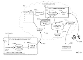
- FIG. 5 is a block diagram illustrating an example cloud-based boiler control system.
- the components of the boiler control system can be collectively implemented in a cloud platform 502 (e.g., cloud platform 202, cloud platform 316, etc.) as a service accessible to authorized users (e.g., subscribers to the cloud-based boiler control system).
- Boiler system 516 is deployed at a plant facility, and comprises one or more boilers (e.g., boilers 102a-n) and one or more loads (e.g., loads 104a-n).
- Industrial and demand data 510 (e.g., industrial data associated with the boilers 102a-n and demand data associated with the loads 104a-n) is collected from the boiler system 516 and sent to the cloud platform 502 via system interface component 404.
- the system interface component 404 can maintain a communication channel between the cloud platform 502 and one or more industrial devices or cloud agent devices on a plant floor associated with the boiler system 516.
- the industrial and demand data 510 is provided to the system interface component 404 directly by one or more cloud-capable industrial devices associated with the boiler system 516 (e.g., field devices, sensors, industrial controllers, human-machine interfaces, telemetry devices, etc.).
- the one or more industrial devices may include an integrated cloud interface component configured to couple the cloud-aware smart device to the system interface component 404 and exchange data with the cloud platform 502.
- the industrial and demand data 510 can be provided to the cloud platform 502 by one or more cloud agent devices that collect data from the industrial devices and push the data to the cloud platform 502, as will be described in more detail below.
- the industrial and demand data 510 can comprise such information as process variable values for a controlled process (e.g., temperatures, pressures, flows, levels, etc.), device configuration information (e.g., configuration parameters, analog output scale factors configured for an industrial controller, etc.), device or system level faults and alarms, machine cycle time information, calculated key performance indicators (KPIs), measured indicators of system performance over time, device or system documentation, device firmware revisions, demand information association with loads, and/or other such information relating to configuration and/or operating characteristics of the boiler system 516.
- KPIs key performance indicators
- the industrial and demand data 510 is moved to historical data storage 506, which comprises cloud storage allocated to the industrial enterprise that owns boiler system 516 for storage and analysis of respective industrial data and/or demand data.
- the cloud-based boiler control system (e.g., the cloud platform 502) generates suitable set point parameters for a given boiler application by leveraging a boiler behavioral model 504 built for the boiler system 516 (e.g., a unique boiler system).
- the boiler behavioral model 504 defines relationships between efficiency and capacity for the boiler system 516, allowing correlation analytics component 408 to determine suitable set point parameters for the boiler system 516.
- Modeling component 410 generates the boiler behavioral model 504 based on big data analysis of the historical system data (e.g., industrial data and demand data) maintained in historical data storage 506. The big data analysis can discover correlations between efficiency and capacity of the boiler system 516, which can be encoded in the boiler behavioral model 504.
- Correlation analytics component 408 analyzes the boiler behavioral model 504 to determine suitable set point parameters determined to yield maximum efficiency.
- Suggested set point parameters 508 are delivered by the client interface component 406 to a client device 514 associated with an authorized plant employee (e.g., a system designer).
- the client device 514 can be a user device (e.g., the user device 306).
- the user of client device 514 may then choose to apply the recommended set point parameters in the boiler system 516 (e.g., a controller of the boiler system 516).
- the client device 514 may interact with client interface component 406 (and thereby with the cloud platform 502) using a cloud interface application executing on the client device.
- Client interface component 406 may deliver the suggested set point parameters 508 to the cloud interface application, or to a controller program development environment executing on the client device 514 (which may include an integrated cloud interface to allow the controller development software to interact with both the cloud platform 502 and an industrial controller).
- Set point parameters 512 can then be downloaded to the boiler system 516 (e.g., a controller of the boiler system 516 using the controller development software).
- the cloud-based architecture described herein supports creation of a boiler control system in the cloud platform 502, thereby leveraging cloud-based analytics and big data analysis to facilitate determining the suggested set point parameters 508 for optimum efficiency and/or capacity associated with the boiler system 516.
- a virtual link is established between efficiency and capacity associated with one or more boilers of the boiler system 516 based on the boiler behavioral model 504 maintained in the cloud platform 502.
- the cloud-based boiler control system can employ an iterative analytical procedure to build the boiler behavioral model 504 and/or determine substantially optimized suggested set point parameters 508 for the boiler system 516.
- the industrial and demand data 510 associated with the boiler system 516 can be monitored and/or collected in the cloud platform 502 and stored in cloud-based historical data storage 506.
- the system uses an incremental learning system, whereby the correlation analytics component 408 leverages the boiler behavioral model 504 to correlate efficiency of the boiler system 516 with capacity of the boiler system 516.
- the modeling component 410 generates the boiler behavioral model 504 based on historical data collected from devices of the boiler system 516, and may iteratively update the boiler behavioral model 504 over time as new data (e.g., new industrial data and/or new demand data) is gathered from the boiler system 516 and correlated in the cloud platform 502.
- new data e.g., new industrial data and/or new demand data
- This iterative process of generating a simulated process response associated with the boiler system 516 and iteratively modifying set point parameters based on the results comprises a set point parameter optimization loop that gradually converges to the suggested set point parameters 508 determined to yield optimal efficiency and/or capacity associated with the boiler system 516.
- the suggested set point parameters 508 can be provided to the client device 514 via the client interface component 406 (e.g., a cloud interface). Therefore, the client interface component 406 can serve as a user interface for the cloud-based boiler control process.
- the client interface component 406 can also generate user prompts offering a user an option to apply the suggested set point parameters 508 to the actual controller of the boiler system 516.
- the client interface component 406 may allow the suggested set point parameters 508 to be exported to a separate controller programming interface for download to the controller.
- the cloud-based boiler control system may also save a record of the suggested set point parameters 508 together with a record of the simulated response data on cloud storage in association with a customer identifier associated with an owner of the boiler system 516, thereby providing a backup of set point parameter settings that can be retrieved at a future time if the controller must be re-configured due to loss of programming, or if a replacement controller requires configuration.
- the client interface component 406 can deliver the suggested set point parameters 508 to the client device 514 upon completion of the iterative set point parameter optimization process (e.g., when the process response satisfies a defined completion criterion). Since the modeling component 410 can update the boiler behavioral model 504 incrementally on the cloud platform 502 as new industrial data and/or new demand data is collected from the boiler system 516, the system may subsequently determine - based on the updated model - that adjustment of the previously determined set point parameters is likely to yield improved system performance, efficiency and/or capacity.
- the cloud-based boiler control system may be configured to automatically re-execute the set point parameter optimization sequence, either periodically or in response to defined conditions (e.g., a determination that the boiler behavioral model 504 has evolved by a defined degree relative to the model that yielded the current set point parameters).
- the client interface component 406 may deliver a notification to one or more client devices if the correlation analytics component 408 determines that new set point parameters determined based on an automatic re-execution of the boiler control sequence are likely to yield an improved system performance, efficiency and/or capacity relative to the current set point parameters (e.g., by comparing the new simulated process response with the previously saved simulated response generated using the current set point parameters).
- the client interface component 406 may deliver the suggested set point parameters 508 to the client device 514 together with the notification, or may deliver only the notification to the client device 514, providing a link to a network location at which the new suggested set point parameters 508 can be viewed and/or retrieved.
- the notification may also include an identification of the particular boiler system to which the new suggested set point parameters 508 are applicable, instructions regarding how to implement the new suggested set point parameters 508 on the industrial controller, etc.
- the client interface component 406 may leverage a customer model (not shown) stored on the cloud platform 502 in association with the customer identifier to determine how notifications regarding the suggested set point parameters 508 should be delivered.
- Example information maintained in the customer model can include a client identifier, client contact information specifying which plant personnel should be notified in the event that new set point parameters are to be recommended, notification preferences specifying how plant personnel should be notified ( e.g., email, mobile phone, text message, etc. ) , preferred technical support personnel to be contacted for support in connection with implementing the set point parameters on the customer's particular industrial controller, service contracts that are active between the customer and the technical support entity, and other such information.
- FIG. 6 illustrates an example reporting architecture supported by one or more embodiments of the cloud-based system described herein.
- data 603 is exported from an HMI application 608 executing on a plant floor (e.g., an HMI application 608 associated with a boiler system), and web pages 602 (e.g., HTML-5 web pages) are generated based on the exported data 603 using an HMI cloud factory 604.
- the data 603 can include, but is not limited to, project XML (extensible markup language) files, data tags, data objects, other data, etc.
- the web pages 602 can comprise one or more graphic reports 606 (e.g., view-only graphical reports) having a similar graphical and data layout to one or more HMI screens of HMI application 608.
- the web pages 602 are deployed to a website via a cloud platform 610 (e.g., cloud platform 202, cloud platform 316, cloud platform 502, etc.), where the pages can be remotely accessed by a client device (e.g., the user device 306, the client device 514, etc.).
- a view-only version of HMI application 608 can be remotely accessed to facilitate remote monitoring of one or more industrial processes.
- the web pages 602 can receive data from one or more cloud-level databases associated with the cloud platform 610. Therefore, a data pipeline (e.g., an automatically-generated data pipeline) can be implemented between the one or more cloud-level databases (e.g., the one or more cloud-level databases associated with the cloud platform 610) and an HMI web service associated with the web pages 602. For example, the data pipeline can be generated based on HMI tag configuration data (e.g., mapping data). Furthermore, the cloud platform 610 can determine which tags to read from the one or more cloud-level databases and/or which tags to write into the web pages 602 (e.g., a browser-based HMI) throughout the data pipeline.
- HMI tag configuration data e.g., mapping data
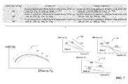
- the industrial data (e.g., collected time-series data) can be sorted by boiler, capacity, efficiency and/or load.
- the analytic engine 314 and/or the correlation analytics component 408 can sort the industrial data (e.g., the collected time-series data) by boiler, capacity, efficiency and/or load.
- an efficiency n-tuple representing a set of efficiencies for all boilers running at that load and a capacity n-tuple representing a set of capacities for all boilers running at that load are determined.
- an efficiency n-tuple 702 can be determined for a 1000 Kg load.
- a first boiler b1 can be associated with 20% efficiency
- a second boiler b2 can be associated with 35% efficiency
- a third boiler b3 can be associated with 40% efficiency.
- a capacity n-tuple 704 can be determined for the 1000 Kg load.
- the first boiler b1 can be associated with 33% capacity
- the second boiler b2 can be associated with 35% capacity
- the third boiler b3 can be associated with 10% capacity. Based on these relationships, efficiency curves can be calculated for each boiler.
- an efficiency curve 706 with respect to capacity can be calculated for the first boiler b1
- an efficiency curve 708 with respect to capacity can be calculated for the second boiler b2
- an efficiency curve 710 with respect to capacity can be calculated for the third boiler b3.
- an efficiency curve 712 with respect to load can be calculated for the first boiler b1, the second boiler b2 and the third boiler b3.
- analytic engine 314 and/or the correlation analytics component 408 can use iterative analysis to determine an optimal efficiency and/or an optimal capacity distribution between the available boilers based on the respective efficiencies, capacities, running costs, fuel consumptions, and/or other factors specific to each boiler.
- system interface component 404 of the cloud-based boiler control system can collect data from devices and assets comprising respective different boiler systems 806 for storage in cloud-based collective historical data storage 804.
- data maintained in collective historical data storage 804 can be collected anonymously with the consent of the respective customers.
- Collective historical data storage 804 can organize the collected data according to device type, system type, application type, applicable industry, or other relevant categories.
- Modeling component 410 can analyze the resulting multi-industry (e.g., multi-boiler and/or multi-boiler system), multi-customer data to learn industry-specific, device-specific, machine-specific, and/or application-specific trends, behavior patterns, thresholds, or other information that can be used to characterize relationships between efficiency and capacity of boilers across different types of systems, equipment, and devices.
- modeling component 410 can perform big data analysis on the multi-enterprise data maintained in collective historical data storage to learn and characterize operational trends or patterns as a function of industry type, application type, equipment in use, industrial asset configuration, device configuration settings, or other such variables. The modeling component 410 can then use results of this analysis to build application-specific boiler behavior models 802 based on an assessment of a particular customer's control system.
- modeling component 410 can identify a subset of the global data stored in collective historical data storage 804 relating to the asset or asset type, and perform analysis on this subset of data to determine how the asset or asset type performs over time for different set point parameters. For example, the modeling component 410 may monitor common industrial data of similar boiler systems, and record the set point parameters used for the respective boiler systems.
- the modeling component 410 can refine the boiler behavioral models 802 to more accurately link efficiency and capacity associated with a boiler system.
- modeling component 410 can learn common operating characteristics of many diverse configurations of boiler assets using different set point parameters at a high degree of granularity and under many different operating contexts.
- modeling component 410 can compare operational behavior of similar boiler applications across different device hardware platform or software configuration settings, and make a determination regarding which combination of hardware, configuration settings, and/or set point parameters yield preferred operational performance. Moreover, modeling component 410 can compare data across different verticals to determine whether system configurations used at one vertical could beneficially be packaged and implemented for another vertical. Some embodiments of the boiler control system can use such determinations as the basis for customer-specific recommendations. In general, collective historical data storage 804, together with modeling component 410, can serve as a repository for knowledge capture and best practices for a wide range of boilers, industries, industrial applications, and device combinations.
- any suitable technique can be used to migrate data from the device-level industrial systems on the plant floor to historical data storage 804.
- the boiler behavior modeling and boiler analytics performed by the modeling component 410 and the correlation analytics component 408 are agnostic with regard to the specific technology used to ingest plant floor data in the cloud platform.
- the analysis of the collected industrial data maintained in historical data storage 804 is decoupled from the particular technologies used to move the industrial data and/or demand data from the plant floor to the cloud platform.
- data from boiler devices and systems can be provided to a cloud platform 902 (e.g., cloud platform 202, cloud platform 316, cloud platform 502, etc.) for storage and analysis using cloud agent devices in some embodiments.
- FIG. 9 is an overview of a system that leverages an agent-based cloud infrastructure to provide data collection and processing services (such as the boiler control services described herein) to manufacturing sites associated with boiler systems. This system can provide remote collection and analysis services in connection with remote boiler control.
- a data concentrator 928 collects plant data from one or more industrial assets (e.g., data associated with one or more boilers and/or one or more loads) at a plant facility.
- These industrial assets can include industrial controllers that monitor and/or control industrial I/O devices, data servers and historians, remote I/O interfaces that remotely interface groups of I/O devices to one or more of the industrial controllers, boilers, loads, other industrial machines, other such assets, etc.
- data concentrator 928 can monitor one or more controller tags defined in a tag archive and store data in local data storage 936 (e.g., a local structured query language, or SQL, server) associated with a historian 938.
- the collected data can include historical data (e.g., alarm history, status history, trend data, etc.), live data values read from the industrial assets, sensor data associated with the industrial assets, alarm data generated by the industrial assets and/or other types of data.
- An on-premise cloud agent 940 is configured to collect the live or historical data from the industrial assets, either directly or by accessing data storage 936 associated with data concentrator 928.
- Cloud agent 940 can execute on any suitable hardware platform (e.g., a server, a LINUX box, etc.), and acts as a generic gateway that collects data items from the various industrial assets on the plant network and packages the collected data according to a generic, uniform data packaging schema used to move the on-premise data to the cloud platform 902.
- Cloud agent 940 provides a software mechanism to dynamically link on-premise-to-cloud gateways.
- Cloud agent 940 provides an expandable data type schema that allows new data types to be added without the need to redeploy the monitoring system to the cloud.
- the cloud agent 940 can intelligently sort and organize the data based on defined criteria, including but not limited to time of occurrence and/or user-defined priorities.
- Cloud agent 940 can be, for example, a service (e.g., a Windows service) that periodically collects and transmits serialized and compressed data into the cloud domain using standard web services over HTTPS/SSL.
- a service e.g., a Windows service
- FIG. 9 depicts data concentrator 928 as the data source for cloud agent 940. This configuration can be useful if there are a large number of data points to monitor, since the data concentrator can 928 can link multiple industrial devices or other data sources to a single cloud agent 940. However, some embodiments of cloud agent 940 can collect data directly from the industrial assets themselves; e.g., through a common industrial protocol link, or through middleware applications such as OPC clients.
- Cloud agent functionality is illustrated in more detail with reference to FIG. 10 .
- On-premise data collection is enabled by a collection of services that function as a virtual support engineer for processing data.
- Data concentrator 928 and cloud agent 940 respectively implement two main functions associated with data collection - data concentration using a historian 938 and associated data storage 936 (e.g., an SQL server), and cloud data enablement using cloud agent services executed by cloud agent 940.
- plant data 1010 e.g., industrial data and/or demand data
- plant data 1010 may comprise time series sensor data made up of thousands of data points updated at a rate of less than a second.
- Collection services component 1002 of cloud agent 940 implements collection services that collect device data, either from data concentrator's associated data storage (e.g., via an SQL query) or directly from the devices themselves via a common industrial protocol (CIP) link or other suitable communication protocol. For example, to obtain data from data concentrator 928, collection services component 1002 may periodically run a data extraction query (e.g., an SQL query) to extract data from data storage 936 associated with data concentrator 928. Collection services component 1002 can then compress the data and store the data in a compressed data file 1012.
- a data extraction query e.g., an SQL query
- Queue processing services executed by queue processing component 1004 can then read the compressed data file 1012 and reference a message queuing database 1014, which maintains and manage customer-specific data collection configuration information, as well as information relating to the customer's subscription to the cloud platform and associated cloud services. Based on configuration information in the message queuing database 1014, queue processing component 1004 packages the compressed data file 1012 into a data packet and pushes the data packet to the cloud platform.
- the cloud agent 940 can support injecting data packets as torrential data 1016.
- Message queuing database 1014 can include site-specific information identifying the data items to be collected (e.g., data tag identifiers), user-defined processing priorities for the data tags, firewall settings that allow cloud agent 940 to communicate with the cloud platform through a plant firewall, and other such configuration information. Configuration information in message queuing database 1014 instructs cloud agent 940 how to communicate with the identified data tags and with the remote data collection services on the cloud platform.
- cloud agent 940 can also perform local analytics on the data prior to moving the data to the cloud platform. This can comprise substantially any type of pre-processing or data refinement that may facilitate efficient transfer of the data to the cloud, prepare the data for enhanced analysis in the cloud, reduce the amount of cloud storage required to store the data, or other such benefits.
- cloud agent 940 may be configured to compress the collected data using any suitable data compression algorithm prior to migrating the data to the cloud platform. This can include detection and deletion of redundant data bits, truncation of precision bits, or other suitable compression operations.
- cloud agent 940 may be configured to aggregate data by combining related data from multiple sources.
- cloud agent 940 may filter the data according to any specified filtering criterion (e.g., filtering criteria defined in a filtering profile stored on the cloud agent). For example, defined filtering criteria may specify that pressure values exceeding a defined setpoint are to be filtered out prior to uploading the pressure values to the cloud.
- filtering criteria may specify that pressure values exceeding a defined setpoint are to be filtered out prior to uploading the pressure values to the cloud.
- cloud agent 940 may also transform a specified subset of the industrial data and/or the demand data from a first format to a second format in accordance with a requirement of a cloud-based analysis application.
- a cloud-based reporting application may require measured values in ASCII format.
- cloud agent 940 can convert a selected subset of the gathered data (e.g., the industrial data and/or the demand data) from floating point format to ASCII prior to pushing the data to the cloud platform for storage and processing. Converting the raw data at the industrial device before uploading to the cloud, rather than requiring this transformation to be performed on the cloud, can reduce the amount of processing load on the cloud side.
- Cloud agent 940 may also associate metadata with selected subsets of the data prior to migration to the cloud, thereby contextualizing the data within the industrial environment (e.g., boiler system environment). For example, cloud agent 940 can tag selected subsets of the data (e.g., the industrial data and/or the demand data) with a time indicator specifying a time at which the data was generated, a quality indicator, boiler identifier, a production area indicator specifying a production area within the industrial enterprise from which the data was collected, a machine or process state indicator specifying a state of a machine or process at the time the data was generated, a personnel identifier specifying an employee on duty at the time the data was generated, or other such contextual metadata. In this way, cloud agent 940 can perform layered processing of the collected data to generate meta-level knowledge that can subsequently be leveraged by cloud-based analysis tools to facilitate enhanced analysis of the data in view of a larger plant context.
- cloud agent 940 can tag selected subsets of the data (e.g., the industrial data and/
- cloud agent 940 can support HTTPS/SSL, certificate authority enabled transmission, and/or unique identity using MAC addresses. Cloud agent 940 can also support store-and-forward capability to ensure data is not lost if the agent becomes disconnected from the cloud.
- cloud agent 940 sends compressed data packet 924 to the cloud-based data collection and monitoring system on cloud platform 902 via a cloud storage fabric 916.
- the data packet 924 conveys parameters and data (compressed and serialized) used by the cloud-side services to reconstruct the domain data structure in the cloud using auxiliary tenant-level manifests.
- the cloud services direct remote storage of the received data into preconditioned transient blobs 910.
- the cloud platform 902 can use agent reasoning and collective bargain features to determine a data storage locale.
- users at the plant facility can dynamically configure one or more priority queues 904 that respectively define how the data packets are processed in the cloud platform 902.
- separate queues may be defined for alarms, live data, and historical data, allowing data to be organized according to these data types.
- the historical data queue can relate to time-series records, which can be accessed through an application programming interface (API) (e.g., an SQL API or other suitable API).
- API application programming interface
- the alarms queue can relate to abnormal situations, where the alarm data can also be accessed through the API.
- This alarms queue can comprise multiple queues associated with different alarm priorities, to allow for individual processing for different alarms having different levels of criticality.
- servers, controllers, switches, etc. can be monitored using a number of protocols, and at a certain point (e.g., at the end of a monitoring cycle) alarms can be queued and cloud agent 940 can send the alarms to the cloud.
- Alarms can be reactive (e.g., alarms that trigger when a motor fails, when a CPU crashes, when an interlock is tripped, etc.) or proactive (e.g., a monitoring system may track consumables on a machine and generate an alarm when time to reorder, monitor cycle counts on a machine and generate an alarm when to schedule preventative maintenance, generate an alarm when temperatures fall outside defined bandwidths, send a notification when a computer's memory is 80% full, etc.).
- the live data queue can relate to substantially real-time monitored data, such as current temperatures, current pressures, current levels, current flow, etc.
- the live data values can also be accessed through the API (e.g., a SQL API).
- the queues described above are not intended to be limiting, and it is to be appreciated that other types of priority queues can be defined according to the needs of the end user. For example, queues may be defined for specific devices or device types (e.g., motor drives) for uploading of device parameter and/or performance data.
- cloud agent 940 can allow the user to define these priority queues 904 from the on-site location and to define how data in each queue is handled. For example, the user can define, for each queue, an upload frequency, a priority level (e.g., which data queues should take processing priority over other data queues), identities of cloud partitions or databases in which data from the respective queues should be stored, and other such information.
- the live data queue may be defined to process live data values that are to be used by a remote operator interface application to view substantially real-time data from the plant facility, while historical data queue may be used to process historian data for archival storage in a historical database on cloud storage (e.g., historical data storage 915). Accordingly, the live data queue may be assigned a higher priority relative to the historical data queue, since data in the live data queue is more time-critical than data in the historical queue.
- users can assign priorities to respective data tags or tag groups at the customer site. These priority assignments can be stored in the message queuing database 1014 of the cloud agent 940. Accordingly, when queue processing component 1004 packages the collected data to be moved to the cloud platform, the collected data items can be packaged into data packets according to priority (as defined in message queuing database 1014), and the respective data packet headers populated with the appropriate priority level. If access to the cloud is unavailable, data will continue to be collected by collection services component 1002 and stored locally on the cloud agent in local storage associated with collections services. When communication to the cloud is restored, the stored data will be forwarded to cloud storage. Queue processing services can also encrypt and send storage account keys to the cloud platform for user verification.
- Message queuing services implemented by queue processing component 1004 of cloud agent 940 encapsulates or packages the compressed data file by adding customer-specific header information to yield a compressed data packed (e.g., compressed data packet 924 of FIG. 9 ).
- the queue processing component 1004 can access a message queuing database (e.g., message queuing database 1014 of FIG. 10 ), which stores customer site configuration information and manages the customer's subscription to the cloud platform services.
- the message queuing database 1014 may include such information as a customer identifier associated with the customer entity associated with the industrial enterprise (e.g., the boiler system), a boiler identifier, a site identifier associated with a particular plant facility from which the data was collected, a priority to be assigned to the data (which may be dependent on the type of information being sent; e.g., alarm data, historical data, live operational data, etc.), information required to facilitate connection to the customer's particular cloud fabric, or other such information.
- the information included in the header is based on this customer-specific information maintained in the message queuing database.
- An example compressed data packet is illustrated in FIG. 11 .
- the cloud agent's message queuing services add a header 1104 to compressed data file 1012 to yield the compressed data packet 924.
- the header 1104 contains customer-specific data read from message queuing database 1014.
- header 1104 can include a unique customer identifier, a site identifier representing a particular plant facility, a boiler identifier, a virtual support engineer identifier, a data priority for the data (e.g., the industrial data and/or the demand data) in the compressed data file 1012, a message type, and a process identifier that specifies a particular manifest application on the cloud platform that should be used to process the data on the cloud side.
- Packaging the data e.g., the industrial data and/or the demand data in this way can allow data from diverse data sources to be packaged together using a uniform, generic data packaging schema so that the data can be moved to the cloud infrastructure
- cloud agent 940 When cloud agent 940 sends a data packet to the cloud-based remote processing service, the service reads the packet's header information to determine a priority assigned to the data (e.g., as defined in a data priority field of the data packet) and sends the data packet (or the compressed data therein) to a selected one of the user defined priority queues 904 based on the priority.
- a data process service 908 processes data in the respective priority queues 904 according to the predefined processing definitions.
- the data processing service includes a worker role 932 that determines how the queued data is to be processed based on manifests (e.g., system manifests, tag manifests, and metric manifests) stored in a customer-specific manifest assembly 934.
- manifests e.g., system manifests, tag manifests, and metric manifests
- the user can interact with cloud agent 940 to configure a new manifest for the new queue, the manifest defining such aspects as processing priority for the data, upload frequency for the data, where the data is to be routed or stored within cloud storage, and other such information.
- Cloud agent 940 can then upload the new manifest 906 together with the data (or independently of the data).
- the new manifest 906 is then added to the customer's manifest assembly 934 with the other manifests defined for the customer, so that worker role 932 can leverage the new manifest 906 to determine how data in the new queue is to be processed.
- This new manifest 906 need only be uploaded to the cloud-based remote monitoring service once.
- the manifest may define where the data is to be stored within cloud storage (e.g., historical data storage 915, an Alarms and Live Data database, etc.), and whether processing of the new data queue is to take priority over other data queues.
- the manifest assembly 934 may only accept a new manifest if the manifest is accompanied by a unique key associated with the client.
- reporting services 914 can deliver data in cloud storage (e.g., from historical data storage 915, or controller gain values generated by correlation analytics component 408) to the client devices 922 in a defined format.
- reporting services 914 can leverage collected data stored in the cloud repository to provide remote operator interfaces to client devices 922 over the Internet.
- An analytic engine 918 executing on the cloud platform 902-and which may include correlation analytics component 408 - can also perform various types of analysis on the data stored in big data storage 912 and provide results to client devices 922.
- FIG. 12 is a block diagram illustrating an example agent architecture for collection of data (e.g., the industrial data and/or the demand data) from on-premise industrial devices according to one or more embodiments.
- data is collected from a number of devices and applications 1202 at the customer site, including an alarm database 1202a, data historian 1202b, motor drives 1202c and 1202d, live data server 1202e, and a customer database 1202f.
- these data sources comprise a diverse, heterogeneous collection of devices and applications, collection and pre-processing of data from these sources can be carried out by generic services 1204 (e.g., service libraries).
- generic services 1204 e.g., service libraries
- Generic services 1204 can include utilities for identifying the data locations (e.g., devices, applications, tags, registers, etc.) from which data (e.g., the industrial data and/or the demand data) is to be retrieved, utilities for compressing or otherwise pre-processing the data, and providing the data to the message queuing layers 1206 of the cloud agents.
- the workload services 1208 of the cloud agents can also utilize generic services 1210 to encapsulate and send the data to the cloud fabric.
- the message queuing layers 1206 and workload services 1208 make up the backbone of the decoupled agent architecture.
- FIGs 13-16 illustrate various methodologies in accordance with one or more embodiments of the subject application. While, for purposes of simplicity of explanation, the one or more methodologies shown herein are shown and described as a series of acts, it is to be understood and appreciated that the subject innovation is not limited by the order of acts, as some acts may, in accordance therewith, occur in a different order and/or concurrently with other acts from that shown and described herein. For example, those skilled in the art will understand and appreciate that a methodology could alternatively be represented as a series of interrelated states or events, such as in a state diagram. Moreover, not all illustrated acts may be required to implement a methodology in accordance with the innovation.
- interaction diagram(s) may represent methodologies, or methods, in accordance with the subject disclosure when disparate entities enact disparate portions of the methodologies.
- two or more of the disclosed example methods can be implemented in combination with each other, to accomplish one or more features or advantages described herein.
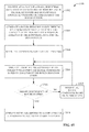
- FIG. 13 illustrates an example methodology 1300 for determining recommended set point capacities for each boiler.
- methodology 1300 can be associated with analytic engine 314 and/or cloud-based boiler control system 402.
- data sets are prepared based on collected time-series boiler data.
- data sets can be prepared based on industrial data associated with one or more boilers and/or demand data associated with one or more loads.
- Operational rules can include, for example, user-defined restrictions, requirements on operation of one or more of the boilers, etc. Operational rules can act as constraints on how capacity is shared between the boilers.
- initial conditions are set.
- the initial conditions can include an initial running capacity (%) for each boiler to satisfy a given load.
- initial conditions can include load data (e.g., fixed load data), capacity data associated with a particular boiler, system efficiency data, fuel data (e.g., fixed fuel data), cost data (e.g., fixed cost data) and/or other data.
- running capacity values for each boiler are adjusted based on at least a calculated system efficiency determined for an operating scenario represented by the initial conditions.
- running capacity values for each boiler can additionally or alternatively be adjusted based on estimated fuel consumption for each boiler and/or a cost of running each boiler under the initial conditions.
- the respective boiler set point parameters corresponding to the determined maximum system efficiency is then recommended.
- the respective boiler set point capacities corresponding to the determined maximum system efficiency can be provided to a user device and/or a controller for a boiler system.
- FIG. 14 illustrates an example methodology 1400 for determining set point parameters for a set of boilers using a cloud-based boiler control system.
- industrial data collected from one or more boilers associated with a boiler automation system is received at a cloud platform.
- the industrial data can be provided to the cloud platform directly by one or more cloud-capable industrial devices associated with the one or more boilers and/or can be provided to the cloud platform by one or more cloud agent devices that collect data from the industrial devices and push the data to the cloud platform.
- the industrial data can comprise such information as process variable values for a controlled process (e.g., temperatures, pressures, flows, levels, etc.), device configuration information (e.g., configuration parameters, analog output scale factors configured for an industrial controller, etc.), device or system level faults and alarms, machine cycle time information, calculated KPIs, measured indicators of system performance over time, device or system documentation, device firmware revisions, or other such information relating to configuration and operating characteristics of the one or more boilers.
- process variable values for a controlled process e.g., temperatures, pressures, flows, levels, etc.
- device configuration information e.g., configuration parameters, analog output scale factors configured for an industrial controller, etc.
- device or system level faults and alarms e.g., machine cycle time information
- calculated KPIs e.g., measured indicators of system performance over time
- device or system documentation e.g., device firmware revisions, or other such information relating to configuration and operating characteristics of the one or more boilers.
- demand data related to one or more loads associated with the boiler automation system is received at the cloud platform.
- demand data associated with one or more loads can be a total demand (e.g., a required demand) associated with the one or more loads.
- a demand associated with each of the one or more loads can be added to determine a total demand (e.g., a required demand) associated with the one or more loads.
- a correlation between efficiency and capacity associated with the one or more boilers is modeled based on analysis of the industrial data and the demand data to yield a boiler behavioral model.
- the boiler behavioral model can be incrementally refined as new industrial data and/or new demand data is collected to produce a progressively higher fidelity model over time.
- an iterative analysis of the boiler behavioral model is performed to identify set point parameters that satisfies a defined criterion. For example, iterative analysis of the boiler behavioral model can be performed to identify set point parameters associated with a maximum efficiency for the boiler automation system.
- the set point parameters are sent to a client device authorized to access the cloud platform. A user of the client device (e.g., the user device) may then choose to implement the set point parameters for the boiler automation system.
- FIG. 15 illustrates an example methodology 1500 for applying an iterative analysis technique in a cloud platform to identify substantially optimal set point parameters for a cloud-based boiler control system.
- industrial data associated with one or more boilers in a boiler system and demand data associated with one or more loads in the boiler system are received at a cloud platform.
- a boiler behavioral model defining relationships between efficiency and capacity of the boiler system is generated based on analysis of the industrial data and the demand data.
- initial conditions are set for iterative analysis.
- an operating scenario for the boiler system is simulated using the initial conditions based on analysis of the boiler behavioral model.
- a decision is made regarding whether the operating scenario for the boiler system is associated with a maximum efficiency.
- the methodology 1500 moves to 1512, where the initial conditions are modified based on tuning rules.
- the tuning rules e.g., defined tuning rules
- the methodology 1500 then returns to 1508, where the operating scenario for the boiler system is simulated using the initial conditions.
- Steps 1508-1512 are repeated until the boiler system is associated with a maximum efficiency, at which time the methodology 1500 moves to 1514, where set point parameters are sent to a client device authorized to access the cloud platform.
- the resulting set point parameters represent recommended set point parameters provided by the cloud-based boiler control system, which can be selectively applied by the end user to the actual boiler system (e.g., by entering or downloading the recommended set point parameters one or more devices of the boiler system).
- Embodiments, systems, and components described herein, as well as industrial control systems and industrial automation environments in which various aspects set forth in the subject specification can be carried out can include computer or network components such as servers, clients, programmable logic controllers (PLCs), automation controllers, communications modules, mobile computers, wireless components, control components and so forth which are capable of interacting across a network.
- Computers and servers include one or more processors-electronic integrated circuits that perform logic operations employing electric signals-configured to execute instructions stored in media such as random access memory (RAM), read only memory (ROM), a hard drives, as well as removable memory devices, which can include memory sticks, memory cards, flash drives, external hard drives, and so on.
- the term PLC or automation controller as used herein can include functionality that can be shared across multiple components, systems, and/or networks.
- one or more PLCs or automation controllers can communicate and cooperate with various network devices across the network. This can include substantially any type of control, communications module, computer, Input/Output (I/O) device, sensor, actuator, and human machine interface (HMI) that communicate via the network, which includes control, automation, and/or public networks.
- the PLC or automation controller can also communicate to and control various other devices such as standard or safety-rated I/O modules including analog, digital, programmed/intelligent I/O modules, other programmable controllers, communications modules, sensors, actuators, output devices, and the like.
- the network can include public networks such as the internet, intranets, and automation networks such as control and information protocol (CIP) networks including DeviceNet, ControlNet, and Ethernet/IP. Other networks include Ethernet, DH/DH+, Remote I/O, Fieldbus, Modbus, Profibus, CAN, wireless networks, serial protocols, and so forth.
- the network devices can include various possibilities (hardware and/or software components). These include components such as switches with virtual local area network (VLAN) capability, LANs, WANs, proxies, gateways, routers, firewalls, virtual private network (VPN) devices, servers, clients, computers, configuration tools, monitoring tools, and/or other devices.
- VLAN virtual local area network
- WANs wide area network
- proxies gateways
- routers virtual private network
- VPN virtual private network
- FIGs. 16 and 17 are intended to provide a brief, general description of a suitable environment in which the various aspects of the disclosed subject matter may be implemented.
- an example environment 1610 for implementing various aspects of the aforementioned subject matter includes a computer 1612.
- the computer 1612 includes a processing unit 1614, a system memory 1616, and a system bus 1618.
- the system bus 1618 couples system components including, but not limited to, the system memory 1616 to the processing unit 1614.
- the processing unit 1614 can be any of various available processors. Multi-core microprocessors and other multiprocessor architectures also can be employed as the processing unit 1614.
- the system bus 1618 can be any of several types of bus structure(s) including the memory bus or memory controller, a peripheral bus or external bus, and/or a local bus using any variety of available bus architectures including, but not limited to, 8-bit bus, Industrial Standard Architecture (ISA), Micro-Channel Architecture (MSA), Extended ISA (EISA), Intelligent Drive Electronics (IDE), VESA Local Bus (VLB), Peripheral Component Interconnect (PCI), Universal Serial Bus (USB), Advanced Graphics Port (AGP), Personal Computer Memory Card International Association bus (PCMCIA), and Small Computer Systems Interface (SCSI).
- ISA Industrial Standard Architecture
- MSA Micro-Channel Architecture
- EISA Extended ISA
- IDE Intelligent Drive Electronics
- VLB VESA Local Bus
- PCI Peripheral Component Interconnect
- USB Universal Serial Bus
- AGP Advanced Graphics Port
- PCMCIA Personal Computer Memory Card International Association bus
- SCSI Small Computer Systems Interface
- the system memory 1616 includes volatile memory 1620 and nonvolatile memory 1622.
- the basic input/output system (BIOS) containing the basic routines to transfer information between elements within the computer 1612, such as during start-up, is stored in nonvolatile memory 1622.
- nonvolatile memory 1622 can include read only memory (ROM), programmable ROM (PROM), electrically programmable ROM (EPROM), electrically erasable PROM (EEPROM), or flash memory.
- Volatile memory 1620 includes random access memory (RAM), which acts as external cache memory.
- RAM is available in many forms such as synchronous RAM (SRAM), dynamic RAM (DRAM), synchronous DRAM (SDRAM), double data rate SDRAM (DDR SDRAM), enhanced SDRAM (ESDRAM), Synchlink DRAM (SLDRAM), and direct Rambus RAM (DRRAM).
- SRAM synchronous RAM
- DRAM dynamic RAM
- SDRAM synchronous DRAM
- DDR SDRAM double data rate SDRAM
- ESDRAM enhanced SDRAM
- SLDRAM Synchlink DRAM
- DRRAM direct Rambus RAM
- Disk storage 1624 includes, but is not limited to, devices like a magnetic disk drive, floppy disk drive, tape drive, Jaz drive, Zip drive, LS-100 drive, flash memory card, or memory stick.
- disk storage 1624 can include storage media separately or in combination with other storage media including, but not limited to, an optical disk drive such as a compact disk ROM device (CD-ROM), CD recordable drive (CD-R Drive), CD rewritable drive (CD-RW Drive) or a digital versatile disk ROM drive (DVD-ROM).
- an optical disk drive such as a compact disk ROM device (CD-ROM), CD recordable drive (CD-R Drive), CD rewritable drive (CD-RW Drive) or a digital versatile disk ROM drive (DVD-ROM).
- a removable or non-removable interface is typically used such as interface 1626.
- FIG. 16 describes software that acts as an intermediary between users and the basic computer resources described in suitable operating environment 1610.
- Such software includes an operating system 1628.
- Operating system 1628 which can be stored on disk storage 1624, acts to control and allocate resources of the computer 1612.
- System applications 1630 take advantage of the management of resources by operating system 1628 through program modules 1632 and program data 1634 stored either in system memory 1616 or on disk storage 1624. It is to be appreciated that one or more embodiments of the subject disclosure can be implemented with various operating systems or combinations of operating systems.
- Input devices 1636 include, but are not limited to, a pointing device such as a mouse, trackball, stylus, touch pad, keyboard, microphone, joystick, game pad, satellite dish, scanner, TV tuner card, digital camera, digital video camera, web camera, and the like. These and other input devices connect to the processing unit 1614 through the system bus 1618 via interface port(s) 1638.
- Interface port(s) 1638 include, for example, a serial port, a parallel port, a game port, and a universal serial bus (USB).
- Output device(s) 1640 use some of the same type of ports as input device(s) 1636.
- a USB port may be used to provide input to computer 1612, and to output information from computer 1612 to an output device 1640.
- Output adapters 1642 are provided to illustrate that there are some output devices 1640 like monitors, speakers, and printers, among other output devices 1640, which require special adapters.
- the output adapters 1642 include, by way of illustration and not limitation, video and sound cards that provide a means of connection between the output device 1640 and the system bus 1618. It should be noted that other devices and/or systems of devices provide both input and output capabilities such as remote computer(s) 1644.
- Computer 1612 can operate in a networked environment using logical connections to one or more remote computers, such as remote computer(s) 1644.
- the remote computer(s) 1644 can be a personal computer, a server, a router, a network PC, a workstation, a microprocessor based appliance, a peer device or other common network node and the like, and typically includes many or all of the elements described relative to computer 1612. For purposes of brevity, only a memory storage device 2246 is illustrated with remote computer(s) 1644.
- Remote computer(s) 1644 is logically connected to computer 1612 through a network interface 1648 and then physically connected via communication connection 1650.
- Network interface 1648 encompasses communication networks such as local-area networks (LAN) and wide-area networks (WAN).
- LAN technologies include Fiber Distributed Data Interface (FDDI), Copper Distributed Data Interface (CDDI), Ethernet/IEEE 802.3, Token Ring/IEEE 802.5 and the like.
- WAN technologies include, but are not limited to, point-to-point links, circuit switching networks like Integrated Services Digital Networks (ISDN) and variations thereon, packet switching networks, and Digital Subscriber Lines (DSL).
- ISDN Integrated Services Digital Networks
- DSL Digital Subscriber Lines
- Communication connection(s) 1650 refers to the hardware/software employed to connect the network interface 1648 to the system bus 1618. While communication connection 1650 is shown for illustrative clarity inside computer 1612, it can also be external to computer 1612.
- the hardware/software necessary for connection to the network interface 1648 includes, for exemplary purposes only, internal and external technologies such as, modems including regular telephone grade modems, cable modems and DSL modems, ISDN adapters, and Ethernet cards.
- FIG. 17 is a schematic block diagram of a sample computing environment 1700 with which the disclosed subject matter can interact.
- the sample computing environment 1700 includes one or more client(s) 1702.
- the client(s) 1702 can be hardware and/or software (e.g., threads, processes, computing devices).
- the sample computing environment 1700 also includes one or more server(s) 1704.
- the server(s) 1704 can also be hardware and/or software (e.g., threads, processes, computing devices).
- the servers 1704 can house threads to perform transformations by employing one or more embodiments as described herein, for example.
- One possible communication between a client 1702 and servers 1704 can be in the form of a data packet adapted to be transmitted between two or more computer processes.
- the sample computing environment 1700 includes a communication framework 1706 that can be employed to facilitate communications between the client(s) 1702 and the server(s) 1704.
- the client(s) 1702 are operably connected to one or more client data store(s) 1708 that can be employed to store information local to the client(s) 1702.
- the server(s) 1704 are operably connected to one or more server data store(s) 1710 that can be employed to store information local to the servers 1704.
- the terms (including a reference to a "means") used to describe such components are intended to correspond, unless otherwise indicated, to any component which performs the specified function of the described component (e.g., a functional equivalent), even though not structurally equivalent to the disclosed structure, which performs the function in the herein illustrated exemplary aspects of the disclosed subject matter.
- the disclosed subject matter includes a system as well as a computer-readable medium having computer-executable instructions for performing the acts and/or events of the various methods of the disclosed subject matter.
- exemplary is used to mean serving as an example, instance, or illustration. Any aspect or design described herein as "exemplary” is not necessarily to be construed as preferred or advantageous over other aspects or designs. Rather, use of the word exemplary is intended to present concepts in a concrete fashion.
- Computer readable media can include but are not limited to magnetic storage devices (e.g., hard disk, floppy disk, magnetic strips...), optical disks [e.g., compact disk (CD), digital versatile disk (DVD)...], smart cards, and flash memory devices (e.g., card, stick, key drive).
- magnetic storage devices e.g., hard disk, floppy disk, magnetic strips
- optical disks e.g., compact disk (CD), digital versatile disk (DVD)...
- smart cards e.g., card, stick, key drive
Applications Claiming Priority (2)
| Application Number | Priority Date | Filing Date | Title |
|---|---|---|---|
| US201461970798P | 2014-03-26 | 2014-03-26 | |
| US14/562,233 US10208947B2 (en) | 2014-03-26 | 2014-12-05 | Cloud-level analytics for boiler networks |
Publications (3)
| Publication Number | Publication Date |
|---|---|
| EP2924572A2 true EP2924572A2 (fr) | 2015-09-30 |
| EP2924572A3 EP2924572A3 (fr) | 2016-08-31 |
| EP2924572B1 EP2924572B1 (fr) | 2019-06-19 |
Family
ID=52823465
Family Applications (1)
| Application Number | Title | Priority Date | Filing Date |
|---|---|---|---|
| EP15160980.7A Active EP2924572B1 (fr) | 2014-03-26 | 2015-03-26 | Réseaux de chaudière analytique au niveau d'un nuage virtuel |
Country Status (2)
| Country | Link |
|---|---|
| US (1) | US10208947B2 (fr) |
| EP (1) | EP2924572B1 (fr) |
Cited By (3)
| Publication number | Priority date | Publication date | Assignee | Title |
|---|---|---|---|---|
| EP3249481A1 (fr) * | 2016-05-25 | 2017-11-29 | Siemens Aktiengesellschaft | Système, contrôleur industriel et procédé configurés pour exécuter une commande en boucle fermée sur des données pour des applications en nuage |
| EP3570121A1 (fr) * | 2018-05-17 | 2019-11-20 | Quorso UK Limited | Réseau, système et procédé de commande |
| WO2023036426A1 (fr) * | 2021-09-09 | 2023-03-16 | Sumitomo SHI FW Energia Oy | Procédé de commande de chaudière à combustion, chaudière à combustion et système de calcul de chaudière |
Families Citing this family (45)
| Publication number | Priority date | Publication date | Assignee | Title |
|---|---|---|---|---|
| US20170315543A1 (en) * | 2015-03-30 | 2017-11-02 | Uop Llc | Evaluating petrochemical plant errors to determine equipment changes for optimized operations |
| US9864823B2 (en) | 2015-03-30 | 2018-01-09 | Uop Llc | Cleansing system for a feed composition based on environmental factors |
| US10095200B2 (en) | 2015-03-30 | 2018-10-09 | Uop Llc | System and method for improving performance of a chemical plant with a furnace |
| WO2016195547A1 (fr) * | 2015-05-29 | 2016-12-08 | Telefonaktiebolaget Lm Ericsson (Publ) | Procédés pour la compression et la décompression d'en-têtes de paquets de protocole internet, dispositifs, programmes d'ordinateur et produits-programmes d'ordinateur |
| US10514683B2 (en) * | 2015-09-16 | 2019-12-24 | Profire Energy, Inc. | Distributed networking system and method to implement a safety state environment |
| US10432754B2 (en) | 2015-09-16 | 2019-10-01 | Profire Energy, Inc | Safety networking protocol and method |
| US11619400B2 (en) * | 2015-11-06 | 2023-04-04 | Mestek, Inc. | Networked boiler system and method |
| US10225216B2 (en) * | 2016-05-25 | 2019-03-05 | Rockwell Automation Technologies, Inc. | Conversation interface agent for manufacturing operation information |
| US10382395B2 (en) * | 2016-07-25 | 2019-08-13 | Honeywell International Inc. | Industrial process control using IP communications with publisher subscriber pattern |
| US10545487B2 (en) | 2016-09-16 | 2020-01-28 | Uop Llc | Interactive diagnostic system and method for managing process model analysis |
| US10489867B2 (en) * | 2016-12-16 | 2019-11-26 | General Electric Company | Apparatus and method for deploying analytics |
| KR101835051B1 (ko) * | 2017-03-13 | 2018-03-08 | 주식회사 귀뚜라미 | IoT 보일러의 제어 시스템 및 방법 |
| US10754359B2 (en) | 2017-03-27 | 2020-08-25 | Uop Llc | Operating slide valves in petrochemical plants or refineries |
| US10678272B2 (en) | 2017-03-27 | 2020-06-09 | Uop Llc | Early prediction and detection of slide valve sticking in petrochemical plants or refineries |
| US10663238B2 (en) | 2017-03-28 | 2020-05-26 | Uop Llc | Detecting and correcting maldistribution in heat exchangers in a petrochemical plant or refinery |
| US10670027B2 (en) | 2017-03-28 | 2020-06-02 | Uop Llc | Determining quality of gas for rotating equipment in a petrochemical plant or refinery |
| US11396002B2 (en) | 2017-03-28 | 2022-07-26 | Uop Llc | Detecting and correcting problems in liquid lifting in heat exchangers |
| US10816947B2 (en) | 2017-03-28 | 2020-10-27 | Uop Llc | Early surge detection of rotating equipment in a petrochemical plant or refinery |
| US11037376B2 (en) | 2017-03-28 | 2021-06-15 | Uop Llc | Sensor location for rotating equipment in a petrochemical plant or refinery |
| US10794401B2 (en) | 2017-03-28 | 2020-10-06 | Uop Llc | Reactor loop fouling monitor for rotating equipment in a petrochemical plant or refinery |
| US10752845B2 (en) | 2017-03-28 | 2020-08-25 | Uop Llc | Using molecular weight and invariant mapping to determine performance of rotating equipment in a petrochemical plant or refinery |
| US10670353B2 (en) | 2017-03-28 | 2020-06-02 | Uop Llc | Detecting and correcting cross-leakage in heat exchangers in a petrochemical plant or refinery |
| US11130111B2 (en) | 2017-03-28 | 2021-09-28 | Uop Llc | Air-cooled heat exchangers |
| US10752844B2 (en) | 2017-03-28 | 2020-08-25 | Uop Llc | Rotating equipment in a petrochemical plant or refinery |
| US10962302B2 (en) | 2017-03-28 | 2021-03-30 | Uop Llc | Heat exchangers in a petrochemical plant or refinery |
| US10844290B2 (en) | 2017-03-28 | 2020-11-24 | Uop Llc | Rotating equipment in a petrochemical plant or refinery |
| US10794644B2 (en) | 2017-03-28 | 2020-10-06 | Uop Llc | Detecting and correcting thermal stresses in heat exchangers in a petrochemical plant or refinery |
| US10695711B2 (en) | 2017-04-28 | 2020-06-30 | Uop Llc | Remote monitoring of adsorber process units |
| US11365886B2 (en) | 2017-06-19 | 2022-06-21 | Uop Llc | Remote monitoring of fired heaters |
| US10913905B2 (en) | 2017-06-19 | 2021-02-09 | Uop Llc | Catalyst cycle length prediction using eigen analysis |
| US10739798B2 (en) | 2017-06-20 | 2020-08-11 | Uop Llc | Incipient temperature excursion mitigation and control |
| US11130692B2 (en) | 2017-06-28 | 2021-09-28 | Uop Llc | Process and apparatus for dosing nutrients to a bioreactor |
| DE102017115517A1 (de) * | 2017-07-11 | 2019-01-17 | Endress+Hauser Process Solutions Ag | Verfahren und Datenumsetzungseinheit zum Überwachen einer Anlage der Automatisierungstechnik |
| US10994240B2 (en) | 2017-09-18 | 2021-05-04 | Uop Llc | Remote monitoring of pressure swing adsorption units |
| US11194317B2 (en) | 2017-10-02 | 2021-12-07 | Uop Llc | Remote monitoring of chloride treaters using a process simulator based chloride distribution estimate |
| US11676061B2 (en) | 2017-10-05 | 2023-06-13 | Honeywell International Inc. | Harnessing machine learning and data analytics for a real time predictive model for a FCC pre-treatment unit |
| US11105787B2 (en) | 2017-10-20 | 2021-08-31 | Honeywell International Inc. | System and method to optimize crude oil distillation or other processing by inline analysis of crude oil properties |
| JP7317029B2 (ja) | 2018-02-12 | 2023-07-28 | アイオーニス ファーマシューティカルズ, インコーポレーテッド | 修飾化合物及びその使用 |
| US10901403B2 (en) | 2018-02-20 | 2021-01-26 | Uop Llc | Developing linear process models using reactor kinetic equations |
| US10734098B2 (en) | 2018-03-30 | 2020-08-04 | Uop Llc | Catalytic dehydrogenation catalyst health index |
| US10953377B2 (en) | 2018-12-10 | 2021-03-23 | Uop Llc | Delta temperature control of catalytic dehydrogenation process reactors |
| US11308447B2 (en) * | 2020-04-02 | 2022-04-19 | Rockwell Automation Technologies, Inc. | Cloud-based collaborative industrial automation design environment |
| BR112022021911A2 (pt) | 2020-04-28 | 2022-12-13 | Buckman Laboratories Int Inc | Método implementado por computador para análise de dados contextuais e intervenção proativa em processos de plantas industriais e sistema |
| EP4147105A1 (fr) * | 2020-05-08 | 2023-03-15 | Uop Llc | Système et procédé de diagnostic d'installation industrielle en temps réel pour la commande et l'analyse de processus de l'installation industrielle |
| US11853100B2 (en) * | 2021-04-12 | 2023-12-26 | EMC IP Holding Company LLC | Automated delivery of cloud native application updates using one or more user-connection gateways |
Family Cites Families (91)
| Publication number | Priority date | Publication date | Assignee | Title |
|---|---|---|---|---|
| USRE39989E1 (en) | 1989-10-31 | 2008-01-01 | Morris Walker C | Method and apparatus for transmission of analog and digital |
| US5793843A (en) | 1989-10-31 | 1998-08-11 | Intelligence Technology Corporation | Method and apparatus for transmission of data and voice |
| US5519605A (en) | 1994-10-24 | 1996-05-21 | Olin Corporation | Model predictive control apparatus and method |
| US7149590B2 (en) | 1996-05-06 | 2006-12-12 | Pavilion Technologies, Inc. | Kiln control and upset recovery using a model predictive control in series with forward chaining |
| US6675226B1 (en) | 1998-11-17 | 2004-01-06 | Rockwell Automation Technologies, Inc. | Network interface for industrial controller providing application programmer interface |
| US6640241B1 (en) | 1999-07-19 | 2003-10-28 | Groove Networks, Inc. | Method and apparatus for activity-based collaboration by a computer system equipped with a communications manager |
| US6850808B2 (en) | 1999-09-24 | 2005-02-01 | Rockwell Software Inc. | Method and system for developing a software program using compound templates |
| US6609034B1 (en) | 2000-03-29 | 2003-08-19 | Epicenter, Incorporated | System and method for remotely controlling and monitoring a plurality of computer systems |
| US20010053992A1 (en) * | 2000-03-31 | 2001-12-20 | Keisuke Eto | Industrial complex, sevice center, method for managing industrial complex, service regulation system, and shared operational information regulation system |
| US7133908B1 (en) | 2000-11-24 | 2006-11-07 | Xerox Corporation | Metrics and status presentation system and method using persistent template-driven web objects |
| US20020123996A1 (en) * | 2001-02-06 | 2002-09-05 | O'brien Christopher | Data mining system, method and apparatus for industrial applications |
| US6587754B2 (en) * | 2001-03-19 | 2003-07-01 | General Electric Company | System and methods for remote management of steam generating systems |
| US6975913B2 (en) | 2001-07-13 | 2005-12-13 | Siemens Aktiengesellschaft | Database system and method for industrial automation services |
| US6842660B2 (en) | 2001-10-31 | 2005-01-11 | Brooks Automation, Inc. | Device and method for communicating data in a process control system |
| US20030212818A1 (en) | 2002-05-08 | 2003-11-13 | Johannes Klein | Content based message dispatch |
| US9565275B2 (en) | 2012-02-09 | 2017-02-07 | Rockwell Automation Technologies, Inc. | Transformation of industrial data into useful cloud information |
| US7159209B1 (en) | 2002-08-19 | 2007-01-02 | Sprint Communications Company L.P. | Inter-application validation tool for use in enterprise architecture modeling |
| US7317969B2 (en) | 2002-09-30 | 2008-01-08 | Ctb Ip, Inc. | Method and system for managing and operating a plurality of farm houses |
| US7809384B2 (en) | 2002-11-05 | 2010-10-05 | Microsoft Corporation | User-input scheduling of synchronization operation on a mobile device based on user activity |
| US7339948B2 (en) | 2003-01-22 | 2008-03-04 | Rockwell Automation Technologies, Inc. | Industrial controller providing deterministic communication on ethernet |
| US7149919B2 (en) | 2003-05-15 | 2006-12-12 | Hewlett-Packard Development Company, L.P. | Disaster recovery system with cascaded resynchronization |
| US20050038579A1 (en) | 2003-08-15 | 2005-02-17 | Lewis Michael W. | Interactive maintenance management alarm handling |
| US20050193285A1 (en) | 2004-02-11 | 2005-09-01 | Eung-Sun Jeon | Method and system for processing fault information in NMS |
| US7676287B2 (en) | 2004-03-03 | 2010-03-09 | Fisher-Rosemount Systems, Inc. | Configuration system and method for abnormal situation prevention in a process plant |
| US7319857B2 (en) | 2004-09-13 | 2008-01-15 | Tekelec | Methods, systems, and computer program products for delivering messaging service messages |
| US7693585B2 (en) | 2004-09-30 | 2010-04-06 | Rockwell Automation Technologies, Inc. | Enabling object oriented capabilities in automation systems |
| US8942834B2 (en) | 2005-06-27 | 2015-01-27 | Rockwell Automation Technologies, Inc. | Method and apparatus for communicating transactions between an industrial controller and a programming interface |
| US20070019641A1 (en) | 2005-07-22 | 2007-01-25 | Rockwell Automation Technologies, Inc. | Execution of industrial automation applications on communication infrastructure devices |
| US20070067458A1 (en) | 2005-09-20 | 2007-03-22 | Rockwell Software, Inc. | Proxy server for integration of industrial automation data over multiple networks |
| US8688780B2 (en) | 2005-09-30 | 2014-04-01 | Rockwell Automation Technologies, Inc. | Peer-to-peer exchange of data resources in a control system |
| CN100399335C (zh) | 2005-11-15 | 2008-07-02 | 李利鹏 | 把源文档转换成目标网页文件的方法 |
| US8527252B2 (en) | 2006-07-28 | 2013-09-03 | Emerson Process Management Power & Water Solutions, Inc. | Real-time synchronized control and simulation within a process plant |
| US20080168092A1 (en) | 2007-01-10 | 2008-07-10 | General Electric Company | Systems and methods for turbine control simulation |
| AU2008239477B2 (en) | 2007-03-29 | 2010-08-05 | Irobot Corporation | Robot operator control unit configuration system and method |
| US8514872B2 (en) | 2007-06-19 | 2013-08-20 | Virtual Hold Technology, Llc | Accessory queue management system and method for interacting with a queuing system |
| US8548777B2 (en) | 2007-09-28 | 2013-10-01 | Rockwell Automation Technologies, Inc. | Automated recommendations from simulation |
| US8516521B2 (en) | 2008-01-14 | 2013-08-20 | Verizon Patent And Licensing Inc. | Interactive learning |
| CN101925866B (zh) | 2008-01-31 | 2016-06-01 | 费希尔-罗斯蒙特系统公司 | 具有用来补偿模型失配的调节的鲁棒的自适应模型预测控制器 |
| US8577655B2 (en) | 2008-06-26 | 2013-11-05 | Siemens Product Lifecycle Management Software Inc. | System and method for constructing virtual NC controllers for machine tool simulation |
| EP2228965A1 (fr) | 2009-03-12 | 2010-09-15 | Alcatel Lucent | Passerelle et procédé pour connecter un réseau IP à un réseau de capteurs |
| US8046444B2 (en) | 2009-03-30 | 2011-10-25 | Rockwell Automation Technologies, Inc. | Universal network adapter for industrial control networks |
| US8204717B2 (en) * | 2009-04-01 | 2012-06-19 | Honeywell International Inc. | Cloud computing as a basis for equipment health monitoring service |
| US9412137B2 (en) | 2009-04-01 | 2016-08-09 | Honeywell International Inc. | Cloud computing for a manufacturing execution system |
| US7970830B2 (en) | 2009-04-01 | 2011-06-28 | Honeywell International Inc. | Cloud computing for an industrial automation and manufacturing system |
| US10033779B2 (en) | 2009-07-08 | 2018-07-24 | Dejero Labs Inc. | Multipath data streaming over multiple wireless networks |
| US8433450B2 (en) | 2009-09-11 | 2013-04-30 | Emerson Process Management Power & Water Solutions, Inc. | Optimized control of power plants having air cooled condensers |
| US8761008B2 (en) * | 2009-10-29 | 2014-06-24 | The Boeing Company | System, apparatus, and method for communication in a tactical network |
| US20110134930A1 (en) | 2009-12-09 | 2011-06-09 | Mclaren Moray | Packet-based networking system |
| US8819701B2 (en) * | 2009-12-12 | 2014-08-26 | Microsoft Corporation | Cloud computing monitoring and management system |
| NZ607113A (en) | 2010-07-08 | 2014-08-29 | Greenbutton Ltd | A method for estimating job run time |
| EP2418554A1 (fr) | 2010-08-02 | 2012-02-15 | ABB Research Ltd. | Procédé et produits de programme informatique pour faciliter la supervision et commande d'un système technique |
| US9338238B2 (en) | 2010-12-03 | 2016-05-10 | Siemens Industry, Inc. | Operation scheduler for a building automation system |
| US8868915B2 (en) | 2010-12-06 | 2014-10-21 | Verizon Patent And Licensing Inc. | Secure authentication for client application access to protected resources |
| US9176742B2 (en) | 2010-12-27 | 2015-11-03 | Microsoft Technology Licensing, Llc | Converting desktop applications to web applications |
| US8756041B2 (en) | 2011-03-07 | 2014-06-17 | Rockwell Automation Technologies, Inc. | Industrial simulation using redirected I/O module configurations |
| JP5754704B2 (ja) | 2011-04-19 | 2015-07-29 | インターナショナル・ビジネス・マシーンズ・コーポレーションInternational Business Machines Corporation | 複数の産業制御システム間の通信を制御するシステム |
| US8798775B2 (en) | 2011-06-28 | 2014-08-05 | Rockwell Automation Technologies, Inc. | Binding graphic elements to controller data |
| JP5765122B2 (ja) | 2011-08-01 | 2015-08-19 | 株式会社Ihi | ラジアルフォイル軸受 |
| US9781205B2 (en) | 2011-09-12 | 2017-10-03 | Microsoft Technology Licensing, Llc | Coordination engine for cloud selection |
| JP5899749B2 (ja) | 2011-09-27 | 2016-04-06 | 株式会社リコー | 制御システム、制御装置、及び制御プログラム |
| US9163828B2 (en) | 2011-10-31 | 2015-10-20 | Emerson Process Management Power & Water Solutions, Inc. | Model-based load demand control |
| US9143563B2 (en) | 2011-11-11 | 2015-09-22 | Rockwell Automation Technologies, Inc. | Integrated and scalable architecture for accessing and delivering data |
| US9953280B2 (en) | 2011-11-15 | 2018-04-24 | Rockwell Automation Technologies, Inc. | Industry-specific workflows in a manufacturing execution system with premier integration |
| US20130124253A1 (en) | 2011-11-15 | 2013-05-16 | Rockwell Automation Technologies, Inc. | Industry-specific workflows in a manufacturing execution system |
| US20130225151A1 (en) | 2011-12-23 | 2013-08-29 | Microsoft Corporation | Mobile device parental control |
| US9384339B2 (en) | 2012-01-13 | 2016-07-05 | Telecommunication Systems, Inc. | Authenticating cloud computing enabling secure services |
| US9529348B2 (en) | 2012-01-24 | 2016-12-27 | Emerson Process Management Power & Water Solutions, Inc. | Method and apparatus for deploying industrial plant simulators using cloud computing technologies |
| US9477936B2 (en) | 2012-02-09 | 2016-10-25 | Rockwell Automation Technologies, Inc. | Cloud-based operator interface for industrial automation |
| US9189210B2 (en) | 2012-02-29 | 2015-11-17 | Avaya Inc. | Using source code generated from a data model file to generate a graphical user interface from objects in a database |
| US9195511B2 (en) | 2012-03-05 | 2015-11-24 | Accenture Global Services Limited | Differentiated service-based graceful degradation layer |
| US8948465B2 (en) | 2012-04-09 | 2015-02-03 | Accenture Global Services Limited | Biometric matching technology |
| US9317623B2 (en) | 2012-04-20 | 2016-04-19 | Yahoo! Inc. | Dynamic webpage image |
| US20130290952A1 (en) | 2012-04-25 | 2013-10-31 | Jerry W. Childers, JR. | Copying Virtual Machine Templates To Cloud Regions |
| EP2660667B1 (fr) | 2012-05-04 | 2021-11-10 | Rockwell Automation Technologies, Inc. | Passerelle de nuage pour systèmes d'information et de commande d'automatisation industrielle |
| WO2013170208A1 (fr) | 2012-05-10 | 2013-11-14 | Digimarc Corporation | Routeur basé sur la position |
| US9282898B2 (en) | 2012-06-25 | 2016-03-15 | Sprint Communications Company L.P. | End-to-end trusted communications infrastructure |
| US9467500B2 (en) | 2012-08-09 | 2016-10-11 | Rockwell Automation Technologies, Inc. | Remote industrial monitoring using a cloud infrastructure |
| US9253054B2 (en) | 2012-08-09 | 2016-02-02 | Rockwell Automation Technologies, Inc. | Remote industrial monitoring and analytics using a cloud infrastructure |
| US20140156234A1 (en) | 2012-12-03 | 2014-06-05 | Rockwell Automation Technologies, Inc., | Input output cloning for industrial automation |
| US20140157368A1 (en) | 2012-12-05 | 2014-06-05 | Srujal SHAH | Software authentication |
| US9665088B2 (en) | 2014-01-31 | 2017-05-30 | Fisher-Rosemount Systems, Inc. | Managing big data in process control systems |
| US9395708B2 (en) | 2013-03-11 | 2016-07-19 | Johnson Controls Technology Company | Systems and methods for adaptive sampling rate adjustment |
| US20140269531A1 (en) | 2013-03-14 | 2014-09-18 | Aliphcom | Intelligent connection management in wireless devices |
| US20140274005A1 (en) | 2013-03-13 | 2014-09-18 | Aliphcom | Intelligent connection management in wireless devices |
| US20140280796A1 (en) | 2013-03-14 | 2014-09-18 | Joyent, Inc. | Systems and methods for providing a distributed service configuration framework |
| US10324423B2 (en) | 2013-03-15 | 2019-06-18 | Fisher-Rosemount Systems, Inc. | Method and apparatus for controlling a process plant with location aware mobile control devices |
| CN203466840U (zh) | 2013-04-16 | 2014-03-05 | 北京天云融创科技有限公司 | 云服务监控系统 |
| CN103701953B (zh) | 2013-12-31 | 2017-05-24 | 北京智谷睿拓技术服务有限公司 | 传输方法及传输装置 |
| US9802309B2 (en) | 2014-07-24 | 2017-10-31 | X Development Llc | Methods and systems for generating instructions for a robotic system to carry out a task |
| WO2016018249A1 (fr) | 2014-07-29 | 2016-02-04 | Hewlett-Packard Development Company, L.P. | Surveillance de la dégradation thermique d'un processeur |
| US10207185B2 (en) | 2015-03-07 | 2019-02-19 | Sony Interactive Entertainment America Llc | Using connection quality history to optimize user experience |
-
2014
- 2014-12-05 US US14/562,233 patent/US10208947B2/en active Active
-
2015
- 2015-03-26 EP EP15160980.7A patent/EP2924572B1/fr active Active
Non-Patent Citations (1)
| Title |
|---|
| None |
Cited By (12)
| Publication number | Priority date | Publication date | Assignee | Title |
|---|---|---|---|---|
| EP3249481A1 (fr) * | 2016-05-25 | 2017-11-29 | Siemens Aktiengesellschaft | Système, contrôleur industriel et procédé configurés pour exécuter une commande en boucle fermée sur des données pour des applications en nuage |
| CN107436582A (zh) * | 2016-05-25 | 2017-12-05 | 西门子公司 | 对基于云的应用的数据闭环控制的系统、控制器及方法 |
| US10353348B2 (en) * | 2016-05-25 | 2019-07-16 | Siemens Aktiengesellschaft | System, industrial controller and method configured to execute a closed loop control on data for cloud based applications |
| EP3249481B1 (fr) | 2016-05-25 | 2019-10-02 | Siemens Aktiengesellschaft | Système, contrôleur industriel et procédé configurés pour exécuter une commande en boucle fermée sur des données pour des applications en nuage |
| EP3611581A1 (fr) * | 2016-05-25 | 2020-02-19 | Siemens Aktiengesellschaft | Système, commande industrielle et procédé conçu pour commander une activité industrielle |
| CN107436582B (zh) * | 2016-05-25 | 2020-06-02 | 西门子公司 | 对基于云的应用的数据闭环控制的系统、控制器及方法 |
| EP3611581B1 (fr) | 2016-05-25 | 2021-11-10 | Siemens Aktiengesellschaft | Commande industrielle et procédé conçu pour commander une activité industrielle |
| EP3570121A1 (fr) * | 2018-05-17 | 2019-11-20 | Quorso UK Limited | Réseau, système et procédé de commande |
| US10938672B2 (en) | 2018-05-17 | 2021-03-02 | Quorso UK Limited | Control network, system and method |
| GB2575710B (en) * | 2018-05-17 | 2023-01-25 | Quorso Uk Ltd | Control network, system and method |
| WO2023036426A1 (fr) * | 2021-09-09 | 2023-03-16 | Sumitomo SHI FW Energia Oy | Procédé de commande de chaudière à combustion, chaudière à combustion et système de calcul de chaudière |
| WO2023036921A1 (fr) * | 2021-09-09 | 2023-03-16 | Sumitomo SHI FW Energia Oy | Procédé de fonctionnement d'un réacteur de libération de chaleur, réacteur de libération de chaleur et système de calcul pour un réacteur de libération de chaleur |
Also Published As
| Publication number | Publication date |
|---|---|
| US10208947B2 (en) | 2019-02-19 |
| US20150276208A1 (en) | 2015-10-01 |
| EP2924572A3 (fr) | 2016-08-31 |
| EP2924572B1 (fr) | 2019-06-19 |
Similar Documents
| Publication | Publication Date | Title |
|---|---|---|
| EP2924572B1 (fr) | Réseaux de chaudière analytique au niveau d'un nuage virtuel | |
| US10764255B2 (en) | Secure command execution from a cloud monitoring system to a remote cloud agent | |
| US11783725B2 (en) | Snapshot management architecture for process control operator training system lifecycle | |
| EP3037901B1 (fr) | Émulation en nuage et modélisation de systèmes d'automatisation | |
| US10740293B2 (en) | Modular control manifest generator for cloud automation | |
| US9971317B2 (en) | Cloud-level industrial controller loop gain tuning based on industrial application type | |
| US10334048B2 (en) | On-premise data collection and ingestion using industrial cloud agents | |
| EP2924571B1 (fr) | Système de gestion de configuration d'un manifeste de cloud | |
| US20220236724A1 (en) | Dynamically reconfigurable data collection agent for fracking pump asset | |
| US10095202B2 (en) | Multiple controllers configuration management interface for system connectivity | |
| US9886012B2 (en) | Component factory for human-machine interface migration to a cloud platform | |
| US9825949B2 (en) | Device authentication to facilitate secure cloud management of industrial data | |
| EP2704401B1 (fr) | Surveillance industrielle à distance utilisant une infrastructure en nuage |
Legal Events
| Date | Code | Title | Description |
|---|---|---|---|
| PUAI | Public reference made under article 153(3) epc to a published international application that has entered the european phase |
Free format text: ORIGINAL CODE: 0009012 |
|
| AK | Designated contracting states |
Kind code of ref document: A2 Designated state(s): AL AT BE BG CH CY CZ DE DK EE ES FI FR GB GR HR HU IE IS IT LI LT LU LV MC MK MT NL NO PL PT RO RS SE SI SK SM TR |
|
| AX | Request for extension of the european patent |
Extension state: BA ME |
|
| PUAL | Search report despatched |
Free format text: ORIGINAL CODE: 0009013 |
|
| AK | Designated contracting states |
Kind code of ref document: A3 Designated state(s): AL AT BE BG CH CY CZ DE DK EE ES FI FR GB GR HR HU IE IS IT LI LT LU LV MC MK MT NL NO PL PT RO RS SE SI SK SM TR |
|
| AX | Request for extension of the european patent |
Extension state: BA ME |
|
| RIC1 | Information provided on ipc code assigned before grant |
Ipc: G06F 9/50 20060101AFI20160722BHEP Ipc: G05B 13/00 20060101ALI20160722BHEP Ipc: G05B 13/04 20060101ALI20160722BHEP |
|
| STAA | Information on the status of an ep patent application or granted ep patent |
Free format text: STATUS: REQUEST FOR EXAMINATION WAS MADE |
|
| 17P | Request for examination filed |
Effective date: 20170213 |
|
| RBV | Designated contracting states (corrected) |
Designated state(s): AL AT BE BG CH CY CZ DE DK EE ES FI FR GB GR HR HU IE IS IT LI LT LU LV MC MK MT NL NO PL PT RO RS SE SI SK SM TR |
|
| STAA | Information on the status of an ep patent application or granted ep patent |
Free format text: STATUS: EXAMINATION IS IN PROGRESS |
|
| 17Q | First examination report despatched |
Effective date: 20180215 |
|
| GRAP | Despatch of communication of intention to grant a patent |
Free format text: ORIGINAL CODE: EPIDOSNIGR1 |
|
| STAA | Information on the status of an ep patent application or granted ep patent |
Free format text: STATUS: GRANT OF PATENT IS INTENDED |
|
| INTG | Intention to grant announced |
Effective date: 20190118 |
|
| GRAS | Grant fee paid |
Free format text: ORIGINAL CODE: EPIDOSNIGR3 |
|
| GRAA | (expected) grant |
Free format text: ORIGINAL CODE: 0009210 |
|
| STAA | Information on the status of an ep patent application or granted ep patent |
Free format text: STATUS: THE PATENT HAS BEEN GRANTED |
|
| AK | Designated contracting states |
Kind code of ref document: B1 Designated state(s): AL AT BE BG CH CY CZ DE DK EE ES FI FR GB GR HR HU IE IS IT LI LT LU LV MC MK MT NL NO PL PT RO RS SE SI SK SM TR |
|
| REG | Reference to a national code |
Ref country code: GB Ref legal event code: FG4D |
|
| REG | Reference to a national code |
Ref country code: CH Ref legal event code: EP |
|
| REG | Reference to a national code |
Ref country code: IE Ref legal event code: FG4D |
|
| REG | Reference to a national code |
Ref country code: AT Ref legal event code: REF Ref document number: 1146367 Country of ref document: AT Kind code of ref document: T Effective date: 20190715 |
|
| REG | Reference to a national code |
Ref country code: DE Ref legal event code: R096 Ref document number: 602015032096 Country of ref document: DE |
|
| REG | Reference to a national code |
Ref country code: NL Ref legal event code: MP Effective date: 20190619 |
|
| PG25 | Lapsed in a contracting state [announced via postgrant information from national office to epo] |
Ref country code: FI Free format text: LAPSE BECAUSE OF FAILURE TO SUBMIT A TRANSLATION OF THE DESCRIPTION OR TO PAY THE FEE WITHIN THE PRESCRIBED TIME-LIMIT Effective date: 20190619 Ref country code: HR Free format text: LAPSE BECAUSE OF FAILURE TO SUBMIT A TRANSLATION OF THE DESCRIPTION OR TO PAY THE FEE WITHIN THE PRESCRIBED TIME-LIMIT Effective date: 20190619 Ref country code: NO Free format text: LAPSE BECAUSE OF FAILURE TO SUBMIT A TRANSLATION OF THE DESCRIPTION OR TO PAY THE FEE WITHIN THE PRESCRIBED TIME-LIMIT Effective date: 20190919 Ref country code: SE Free format text: LAPSE BECAUSE OF FAILURE TO SUBMIT A TRANSLATION OF THE DESCRIPTION OR TO PAY THE FEE WITHIN THE PRESCRIBED TIME-LIMIT Effective date: 20190619 Ref country code: AL Free format text: LAPSE BECAUSE OF FAILURE TO SUBMIT A TRANSLATION OF THE DESCRIPTION OR TO PAY THE FEE WITHIN THE PRESCRIBED TIME-LIMIT Effective date: 20190619 Ref country code: LT Free format text: LAPSE BECAUSE OF FAILURE TO SUBMIT A TRANSLATION OF THE DESCRIPTION OR TO PAY THE FEE WITHIN THE PRESCRIBED TIME-LIMIT Effective date: 20190619 |
|
| REG | Reference to a national code |
Ref country code: LT Ref legal event code: MG4D |
|
| PG25 | Lapsed in a contracting state [announced via postgrant information from national office to epo] |
Ref country code: GR Free format text: LAPSE BECAUSE OF FAILURE TO SUBMIT A TRANSLATION OF THE DESCRIPTION OR TO PAY THE FEE WITHIN THE PRESCRIBED TIME-LIMIT Effective date: 20190920 Ref country code: BG Free format text: LAPSE BECAUSE OF FAILURE TO SUBMIT A TRANSLATION OF THE DESCRIPTION OR TO PAY THE FEE WITHIN THE PRESCRIBED TIME-LIMIT Effective date: 20190919 Ref country code: RS Free format text: LAPSE BECAUSE OF FAILURE TO SUBMIT A TRANSLATION OF THE DESCRIPTION OR TO PAY THE FEE WITHIN THE PRESCRIBED TIME-LIMIT Effective date: 20190619 Ref country code: LV Free format text: LAPSE BECAUSE OF FAILURE TO SUBMIT A TRANSLATION OF THE DESCRIPTION OR TO PAY THE FEE WITHIN THE PRESCRIBED TIME-LIMIT Effective date: 20190619 |
|
| REG | Reference to a national code |
Ref country code: AT Ref legal event code: MK05 Ref document number: 1146367 Country of ref document: AT Kind code of ref document: T Effective date: 20190619 |
|
| PG25 | Lapsed in a contracting state [announced via postgrant information from national office to epo] |
Ref country code: RO Free format text: LAPSE BECAUSE OF FAILURE TO SUBMIT A TRANSLATION OF THE DESCRIPTION OR TO PAY THE FEE WITHIN THE PRESCRIBED TIME-LIMIT Effective date: 20190619 Ref country code: CZ Free format text: LAPSE BECAUSE OF FAILURE TO SUBMIT A TRANSLATION OF THE DESCRIPTION OR TO PAY THE FEE WITHIN THE PRESCRIBED TIME-LIMIT Effective date: 20190619 Ref country code: SK Free format text: LAPSE BECAUSE OF FAILURE TO SUBMIT A TRANSLATION OF THE DESCRIPTION OR TO PAY THE FEE WITHIN THE PRESCRIBED TIME-LIMIT Effective date: 20190619 Ref country code: EE Free format text: LAPSE BECAUSE OF FAILURE TO SUBMIT A TRANSLATION OF THE DESCRIPTION OR TO PAY THE FEE WITHIN THE PRESCRIBED TIME-LIMIT Effective date: 20190619 Ref country code: PT Free format text: LAPSE BECAUSE OF FAILURE TO SUBMIT A TRANSLATION OF THE DESCRIPTION OR TO PAY THE FEE WITHIN THE PRESCRIBED TIME-LIMIT Effective date: 20191021 Ref country code: AT Free format text: LAPSE BECAUSE OF FAILURE TO SUBMIT A TRANSLATION OF THE DESCRIPTION OR TO PAY THE FEE WITHIN THE PRESCRIBED TIME-LIMIT Effective date: 20190619 Ref country code: NL Free format text: LAPSE BECAUSE OF FAILURE TO SUBMIT A TRANSLATION OF THE DESCRIPTION OR TO PAY THE FEE WITHIN THE PRESCRIBED TIME-LIMIT Effective date: 20190619 |
|
| PG25 | Lapsed in a contracting state [announced via postgrant information from national office to epo] |
Ref country code: IT Free format text: LAPSE BECAUSE OF FAILURE TO SUBMIT A TRANSLATION OF THE DESCRIPTION OR TO PAY THE FEE WITHIN THE PRESCRIBED TIME-LIMIT Effective date: 20190619 Ref country code: ES Free format text: LAPSE BECAUSE OF FAILURE TO SUBMIT A TRANSLATION OF THE DESCRIPTION OR TO PAY THE FEE WITHIN THE PRESCRIBED TIME-LIMIT Effective date: 20190619 Ref country code: IS Free format text: LAPSE BECAUSE OF FAILURE TO SUBMIT A TRANSLATION OF THE DESCRIPTION OR TO PAY THE FEE WITHIN THE PRESCRIBED TIME-LIMIT Effective date: 20191019 Ref country code: SM Free format text: LAPSE BECAUSE OF FAILURE TO SUBMIT A TRANSLATION OF THE DESCRIPTION OR TO PAY THE FEE WITHIN THE PRESCRIBED TIME-LIMIT Effective date: 20190619 |
|
| PG25 | Lapsed in a contracting state [announced via postgrant information from national office to epo] |
Ref country code: TR Free format text: LAPSE BECAUSE OF FAILURE TO SUBMIT A TRANSLATION OF THE DESCRIPTION OR TO PAY THE FEE WITHIN THE PRESCRIBED TIME-LIMIT Effective date: 20190619 |
|
| PG25 | Lapsed in a contracting state [announced via postgrant information from national office to epo] |
Ref country code: PL Free format text: LAPSE BECAUSE OF FAILURE TO SUBMIT A TRANSLATION OF THE DESCRIPTION OR TO PAY THE FEE WITHIN THE PRESCRIBED TIME-LIMIT Effective date: 20190619 Ref country code: DK Free format text: LAPSE BECAUSE OF FAILURE TO SUBMIT A TRANSLATION OF THE DESCRIPTION OR TO PAY THE FEE WITHIN THE PRESCRIBED TIME-LIMIT Effective date: 20190619 |
|
| PG25 | Lapsed in a contracting state [announced via postgrant information from national office to epo] |
Ref country code: IS Free format text: LAPSE BECAUSE OF FAILURE TO SUBMIT A TRANSLATION OF THE DESCRIPTION OR TO PAY THE FEE WITHIN THE PRESCRIBED TIME-LIMIT Effective date: 20200224 |
|
| REG | Reference to a national code |
Ref country code: DE Ref legal event code: R097 Ref document number: 602015032096 Country of ref document: DE |
|
| PLBE | No opposition filed within time limit |
Free format text: ORIGINAL CODE: 0009261 |
|
| STAA | Information on the status of an ep patent application or granted ep patent |
Free format text: STATUS: NO OPPOSITION FILED WITHIN TIME LIMIT |
|
| PG2D | Information on lapse in contracting state deleted |
Ref country code: IS |
|
| 26N | No opposition filed |
Effective date: 20200603 |
|
| PG25 | Lapsed in a contracting state [announced via postgrant information from national office to epo] |
Ref country code: SI Free format text: LAPSE BECAUSE OF FAILURE TO SUBMIT A TRANSLATION OF THE DESCRIPTION OR TO PAY THE FEE WITHIN THE PRESCRIBED TIME-LIMIT Effective date: 20190619 |
|
| PG25 | Lapsed in a contracting state [announced via postgrant information from national office to epo] |
Ref country code: MC Free format text: LAPSE BECAUSE OF FAILURE TO SUBMIT A TRANSLATION OF THE DESCRIPTION OR TO PAY THE FEE WITHIN THE PRESCRIBED TIME-LIMIT Effective date: 20190619 |
|
| REG | Reference to a national code |
Ref country code: CH Ref legal event code: PL |
|
| REG | Reference to a national code |
Ref country code: BE Ref legal event code: MM Effective date: 20200331 |
|
| PG25 | Lapsed in a contracting state [announced via postgrant information from national office to epo] |
Ref country code: LU Free format text: LAPSE BECAUSE OF NON-PAYMENT OF DUE FEES Effective date: 20200326 |
|
| PG25 | Lapsed in a contracting state [announced via postgrant information from national office to epo] |
Ref country code: CH Free format text: LAPSE BECAUSE OF NON-PAYMENT OF DUE FEES Effective date: 20200331 Ref country code: IE Free format text: LAPSE BECAUSE OF NON-PAYMENT OF DUE FEES Effective date: 20200326 Ref country code: LI Free format text: LAPSE BECAUSE OF NON-PAYMENT OF DUE FEES Effective date: 20200331 |
|
| PG25 | Lapsed in a contracting state [announced via postgrant information from national office to epo] |
Ref country code: BE Free format text: LAPSE BECAUSE OF NON-PAYMENT OF DUE FEES Effective date: 20200331 |
|
| PG25 | Lapsed in a contracting state [announced via postgrant information from national office to epo] |
Ref country code: MT Free format text: LAPSE BECAUSE OF FAILURE TO SUBMIT A TRANSLATION OF THE DESCRIPTION OR TO PAY THE FEE WITHIN THE PRESCRIBED TIME-LIMIT Effective date: 20190619 Ref country code: CY Free format text: LAPSE BECAUSE OF FAILURE TO SUBMIT A TRANSLATION OF THE DESCRIPTION OR TO PAY THE FEE WITHIN THE PRESCRIBED TIME-LIMIT Effective date: 20190619 |
|
| PG25 | Lapsed in a contracting state [announced via postgrant information from national office to epo] |
Ref country code: MK Free format text: LAPSE BECAUSE OF FAILURE TO SUBMIT A TRANSLATION OF THE DESCRIPTION OR TO PAY THE FEE WITHIN THE PRESCRIBED TIME-LIMIT Effective date: 20190619 |
|
| PGFP | Annual fee paid to national office [announced via postgrant information from national office to epo] |
Ref country code: FR Payment date: 20230222 Year of fee payment: 9 |
|
| PGFP | Annual fee paid to national office [announced via postgrant information from national office to epo] |
Ref country code: GB Payment date: 20230221 Year of fee payment: 9 Ref country code: DE Payment date: 20230221 Year of fee payment: 9 |
|
| P01 | Opt-out of the competence of the unified patent court (upc) registered |
Effective date: 20230404 |