EP2924509A1 - Inspection method for sheet detection device, sheet detection device, and inspection apparatus - Google Patents
Inspection method for sheet detection device, sheet detection device, and inspection apparatus Download PDFInfo
- Publication number
- EP2924509A1 EP2924509A1 EP15160810.6A EP15160810A EP2924509A1 EP 2924509 A1 EP2924509 A1 EP 2924509A1 EP 15160810 A EP15160810 A EP 15160810A EP 2924509 A1 EP2924509 A1 EP 2924509A1
- Authority
- EP
- European Patent Office
- Prior art keywords
- sheet
- detection
- distance
- optical sensor
- reflective optical
- Prior art date
- Legal status (The legal status is an assumption and is not a legal conclusion. Google has not performed a legal analysis and makes no representation as to the accuracy of the status listed.)
- Granted
Links
- 238000001514 detection method Methods 0.000 title claims abstract description 300
- 238000000034 method Methods 0.000 title claims abstract description 50
- 238000007689 inspection Methods 0.000 title claims description 71
- 230000003287 optical effect Effects 0.000 claims description 58
- 239000011521 glass Substances 0.000 claims description 35
- 230000008859 change Effects 0.000 claims description 9
- 230000008569 process Effects 0.000 abstract description 29
- 238000012545 processing Methods 0.000 description 47
- 238000004891 communication Methods 0.000 description 8
- 230000001174 ascending effect Effects 0.000 description 7
- 230000007246 mechanism Effects 0.000 description 6
- 230000006870 function Effects 0.000 description 4
- 230000002093 peripheral effect Effects 0.000 description 3
- 238000002834 transmittance Methods 0.000 description 3
- 238000010586 diagram Methods 0.000 description 2
- 230000005611 electricity Effects 0.000 description 2
- 230000004048 modification Effects 0.000 description 2
- 238000012986 modification Methods 0.000 description 2
- 230000004044 response Effects 0.000 description 2
- 238000012546 transfer Methods 0.000 description 2
- 230000003321 amplification Effects 0.000 description 1
- 230000000694 effects Effects 0.000 description 1
- 238000003384 imaging method Methods 0.000 description 1
- 230000010365 information processing Effects 0.000 description 1
- 239000004973 liquid crystal related substance Substances 0.000 description 1
- 238000004519 manufacturing process Methods 0.000 description 1
- 238000003199 nucleic acid amplification method Methods 0.000 description 1
- 238000011144 upstream manufacturing Methods 0.000 description 1
Images


Classifications
-
- G—PHYSICS
- G01—MEASURING; TESTING
- G01B—MEASURING LENGTH, THICKNESS OR SIMILAR LINEAR DIMENSIONS; MEASURING ANGLES; MEASURING AREAS; MEASURING IRREGULARITIES OF SURFACES OR CONTOURS
- G01B11/00—Measuring arrangements characterised by the use of optical techniques
- G01B11/14—Measuring arrangements characterised by the use of optical techniques for measuring distance or clearance between spaced objects or spaced apertures
-
- G—PHYSICS
- G03—PHOTOGRAPHY; CINEMATOGRAPHY; ANALOGOUS TECHNIQUES USING WAVES OTHER THAN OPTICAL WAVES; ELECTROGRAPHY; HOLOGRAPHY
- G03G—ELECTROGRAPHY; ELECTROPHOTOGRAPHY; MAGNETOGRAPHY
- G03G15/00—Apparatus for electrographic processes using a charge pattern
- G03G15/55—Self-diagnostics; Malfunction or lifetime display
-
- G—PHYSICS
- G01—MEASURING; TESTING
- G01B—MEASURING LENGTH, THICKNESS OR SIMILAR LINEAR DIMENSIONS; MEASURING ANGLES; MEASURING AREAS; MEASURING IRREGULARITIES OF SURFACES OR CONTOURS
- G01B9/00—Measuring instruments characterised by the use of optical techniques
-
- G—PHYSICS
- G03—PHOTOGRAPHY; CINEMATOGRAPHY; ANALOGOUS TECHNIQUES USING WAVES OTHER THAN OPTICAL WAVES; ELECTROGRAPHY; HOLOGRAPHY
- G03G—ELECTROGRAPHY; ELECTROPHOTOGRAPHY; MAGNETOGRAPHY
- G03G15/00—Apparatus for electrographic processes using a charge pattern
- G03G15/60—Apparatus which relate to the handling of originals
- G03G15/607—Apparatus which relate to the handling of originals for detecting size, presence or position of original
-
- H—ELECTRICITY
- H04—ELECTRIC COMMUNICATION TECHNIQUE
- H04N—PICTORIAL COMMUNICATION, e.g. TELEVISION
- H04N1/00—Scanning, transmission or reproduction of documents or the like, e.g. facsimile transmission; Details thereof
- H04N1/00681—Detecting the presence, position or size of a sheet or correcting its position before scanning
-
- H—ELECTRICITY
- H04—ELECTRIC COMMUNICATION TECHNIQUE
- H04N—PICTORIAL COMMUNICATION, e.g. TELEVISION
- H04N1/00—Scanning, transmission or reproduction of documents or the like, e.g. facsimile transmission; Details thereof
- H04N1/00681—Detecting the presence, position or size of a sheet or correcting its position before scanning
- H04N1/00684—Object of the detection
- H04N1/00726—Other properties of the sheet, e.g. curvature or reflectivity
-
- H—ELECTRICITY
- H04—ELECTRIC COMMUNICATION TECHNIQUE
- H04N—PICTORIAL COMMUNICATION, e.g. TELEVISION
- H04N1/00—Scanning, transmission or reproduction of documents or the like, e.g. facsimile transmission; Details thereof
- H04N1/00681—Detecting the presence, position or size of a sheet or correcting its position before scanning
- H04N1/00742—Detection methods
- H04N1/0075—Detecting a change in reflectivity
-
- G—PHYSICS
- G03—PHOTOGRAPHY; CINEMATOGRAPHY; ANALOGOUS TECHNIQUES USING WAVES OTHER THAN OPTICAL WAVES; ELECTROGRAPHY; HOLOGRAPHY
- G03G—ELECTROGRAPHY; ELECTROPHOTOGRAPHY; MAGNETOGRAPHY
- G03G2215/00—Apparatus for electrophotographic processes
- G03G2215/00172—Apparatus for electrophotographic processes relative to the original handling
- G03G2215/00324—Document property detectors
-
- G—PHYSICS
- G03—PHOTOGRAPHY; CINEMATOGRAPHY; ANALOGOUS TECHNIQUES USING WAVES OTHER THAN OPTICAL WAVES; ELECTROGRAPHY; HOLOGRAPHY
- G03G—ELECTROGRAPHY; ELECTROPHOTOGRAPHY; MAGNETOGRAPHY
- G03G2215/00—Apparatus for electrophotographic processes
- G03G2215/00362—Apparatus for electrophotographic processes relating to the copy medium handling
- G03G2215/00535—Stable handling of copy medium
- G03G2215/00611—Detector details, e.g. optical detector
- G03G2215/00616—Optical detector
Definitions
- the present disclosure relates to an inspection technique for sheet detection devices including reflective optical sensors for detecting sheets such as documents and print sheets that are conveyed or placed in image processing apparatuses such as image forming apparatuses and image reading apparatuses.
- a reflective optical sensor is used for detecting a size of a document to be read or determining whether or not a document is in a predetermined detection area.
- the reflective optical sensor applies light to a document to be detected, and receives light reflected by the document.
- the received-light signal is outputted as an output signal from the reflective optical sensor, and is used for detecting the size of the document or determining whether or not the document is in the predetermined detection area.
- the output signal from the reflective optical sensor varies according to an image density in a document to be detected, and a distance to the document. That is, the brighter the image in the document to be detected is, the greater a value of the output signal from the reflective optical sensor is. Further, the less a distance between the reflective optical sensor and the document to be detected is, the greater the value of the output signal therefrom is.
- An inspection method for a sheet detection device is an inspection method for inspecting a sheet detection device that determines whether or not a sheet is in a detection area based on comparison between an output from a reflective optical sensor that outputs a signal according to an image density of the sheet to be detected and a distance to the sheet, and a predetermined threshold value.
- the inspection method includes a first step, a second step, and a third step.
- the sheet detection device is caused to perform a detection operation for a reference sheet while changing a distance between the reflective optical sensor and the reference sheet having a predetermined image density, and detecting a distance between the reflective optical sensor and the reference sheet when a sheet detection signal indicating that the reference sheet is detected is outputted by the sheet detection device.
- the second step whether or not a detection distance detected in the first step is equal to a predetermined reference value, is determined.
- an amount of light emission from a light emitter in the reflective optical sensor is changed when the detection distance detected in the first step is determined, in the second step, as being unequal to the reference value.
- the first step, the second step, and the third step are repeated until the detection distance detected in the first step is determined, in the second step, as being equal to the reference value.
- a sheet detection device includes a sheet detection portion, a support portion, a driving portion, a first control portion, a second control portion, a distance detection portion, and a determination portion.
- the sheet detection portion is configured to determine whether or not a sheet is in a detection area, based on comparison between an output from a reflective optical sensor that outputs a signal according to an image density of the sheet to be detected and a distance to the sheet, and a predetermined threshold value.
- the support portion is configured to support the reflective optical sensor such that the reflective optical sensor is movable in an approaching direction and a retreating direction relative to the sheet.
- the driving portion is configured to drive the reflective optical sensor in the approaching direction and the retreating direction.
- the first control portion is configured to cause the driving portion to change a distance between the sheet and the reflective optical sensor.
- the second control portion is configured to control an amount of light emission from a light emitter in the reflective optical sensor.
- the distance detection portion is configured to operate such that, according to control by the first control portion and the second control portion, the sheet detection portion performs a detection operation for a reference sheet while changing a distance between the reflective optical sensor and the reference sheet having a predetermined image density, and to detect a distance between the reflective optical sensor and the reference sheet when a sheet detection signal indicating that the reference sheet is detected is outputted by the sheet detection portion.
- the determination portion is configured to determine whether or not a detection distance detected by the distance detection portion is equal to a predetermined reference value.
- the second control portion changes an amount of light emission from the light emitter when the determination portion determines that the detection distance detected by the distance detection portion is unequal to the reference value, and repeatedly changes an amount of light emission until the determination portion determines that the detection distance detected by the distance detection portion is equal to the reference value.
- An inspection apparatus capable of communicating with a sheet detection device that includes: a reflective optical sensor that outputs a signal according to an image density of a sheet to be detected, and a distance to the sheet; a support portion that supports the reflective optical sensor such that the reflective optical sensor is movable in an approaching direction and a retreating direction relative to the sheet; and a driving portion that drives the reflective optical sensor in the approaching direction and the retreating direction, and that determines whether or not the sheet is in a detection area, based on comparison between an output from the reflective optical sensor and a predetermined threshold value, the inspection apparatus inspecting the sheet detection device.
- the inspection apparatus includes a first control portion, a second control portion, a distance detection portion, and a determination portion.
- the first control portion is configured to cause the driving portion to change a distance between the sheet and the reflective optical sensor.
- the second control portion is configured to control an amount of light emission from a light emitter in the reflective optical sensor.
- the distance detection portion is configured to operate such that, according to control by the first control portion and the second control portion, the sheet detection device performs a detection operation for a reference sheet while changing a distance between the reflective optical sensor and the reference sheet having a predetermined image density, and to detect a distance between the reflective optical sensor and the reference sheet when a sheet detection signal indicating that the reference sheet is detected is outputted by the sheet detection device.
- the determination portion is configured to determine whether or not a detection distance detected by the distance detection portion is equal to a predetermined reference value.
- the second control portion changes an amount of light emission from the light emitter when the determination portion determines that the detection distance detected by the distance detection portion is unequal to the reference value, and repeatedly changes an amount of light emission until the determination portion determines that the detection distance detected by the distance detection portion is equal to the reference value.
- the image processing apparatus 1 is a multifunction peripheral that includes an image reading function, a facsimile function, an image forming function, and the like.
- the image processing apparatus 1 includes an image reading portion 2, a document cover 3, an automatic document feeding device (Auto Document Feeder; hereinafter, referred to as an ADF) 4, an image forming portion 5, an operation display portion 6 (see FIG. 2 ), a sheet feed cassette 7, a communication interface (I/F) portion 8 (see FIG. 2 ), and a control portion 9 (see FIG. 2 ) that controls the above components.
- the image processing apparatus 1 that is a multifunction peripheral will be described.
- the image processing apparatus of the present disclosure is not limited thereto, and may be implemented as, for example, a printer, a facsimile device, a copying machine, or a scanner device.
- the image reading portion 2 executes an image reading process for reading image data from a document.
- the image reading portion 2 includes a contact glass 10 (glass plate), a reading unit 11, mirrors 12, 13, an optical lens 14, a Charge Coupled Device (CCD) 15, and the like.
- a contact glass 10 glass plate
- a reading unit 11 mirrors 12, 13, an optical lens 14
- CCD Charge Coupled Device
- the reading unit 11 includes an LED light source 16 and a mirror 17, and can be moved in a sub-scanning direction 18 (the left-right direction in FIG. 1 ) by a movement mechanism (not shown) using a driving motor such as a stepping motor.
- a driving motor such as a stepping motor.
- the mirror 17 When light is applied from the LED light source 16, the mirror 17 reflects, toward the mirror 12, light reflected by a document or a rear surface of the document cover 3. The light reflected by the mirror 17 is guided to the optical lens 14 through the mirrors 12, 13. The optical lens 14 focuses the incident light on the CCD 15.
- the CCD 15 is a photoelectric converter that converts the received light into an electric signal (voltage) according to an amount of the received light (intensity of brightness), to output the electric signal to the control portion 9.
- the control portion 9 generates image data of a document by subjecting the electric signal from the CCD 15 to image processing.
- the CCD 15 is used as an imaging device.
- a reading mechanism that includes a contact image sensor (CIS) having a focal length shorter than the CCD 15 may be used instead of the reading mechanism using the CCD 15, a reading mechanism that includes a contact image sensor (CIS) having a focal length shorter than the CCD 15 may be used.
- CIS contact image sensor
- the document cover 3 is pivotably mounted. By the document cover 3 being operated to pivot, the contact glass 10 on the upper surface of the image reading portion 2 is opened or closed.
- a cover-opening detection sensor (not shown) such as a limit switch is provided.
- the cover-opening detection sensor is actuated to output a detection signal (cover-opening detection signal) to the control portion 9.
- the image reading portion 2 reads an image of a document in the following procedure. Firstly, the document is placed on the contact glass 10, and the document cover 3 is then put into a closed position. Thereafter, when an image reading instruction is inputted through the operation display portion 6, one line of light is sequentially applied continuously from the LED light source 16 while the reading unit 11 is being moved rightward in the sub-scanning direction 18. Light reflected by the document or the rear surface of the document cover 3 is guided to the CCD 15 through the mirrors 17, 13, and 14, and the optical lens 14, and light amount data based on an amount of light received by the CCD 15 is sequentially outputted to the control portion 9. When light amount data for the entirety of the area to which light has been applied is obtained, the control portion 9 processes the light amount data, to generate image data of the document based on the light amount data.
- the ADF 4 is provided in the document cover 3.
- the ADF 4 sequentially feeds documents set on a document set portion 19, by means of a plurality of feed rollers, and moves the document rightward in the sub-scanning direction 18 through an automatic document reading position defined on the contact glass 10.
- the reading unit 11 is positioned below the automatic document reading position, and an image of the document being moved is read by the reading unit 11 at this position.
- the image forming portion 5 executes an image forming process (printing process) by electrophotography.
- the image forming portion 5 executes the image forming process according to image data read by the image reading portion 2 or a printing job inputted through the communication I/F portion 8 from an external information processing apparatus such as a personal computer.
- the image forming portion 5 includes a photosensitive drum 20, a charging portion 21, a developing portion 22, a toner container 23, a transfer roller 24, an electricity removing portion 25, a fixing roller 26, a pressure roller 27, and the like.
- the image forming portion 5 using electrophotography is illustrated.
- the image forming portion 5 is not limited to an image forming portion using electrophotography, and may be an image forming portion using an inkjet recording mode, or an image forming portion using another recording mode or printing mode.
- an image forming process on a print sheet fed from the sheet feed cassette 7 is performed in the following procedure. Firstly, when a printing job including a print instruction is inputted through the communication I/F portion 8, the photosensitive drum 20 is uniformly charged at a predetermined potential by the charging portion 21. Subsequently, light based on image data included in the printing job is applied to the surface of the photosensitive drum 20 by a laser scanner unit (not shown). Thus, an electrostatic latent image is formed on the surface of the photosensitive drum 20. The electrostatic latent image on the photosensitive drum 20 is developed (visualized) into a toner image by the developing portion 22. Toner (developer) is additionally supplied to the developing portion 22 from the toner container 23.
- the toner image formed on the photosensitive drum 20 is transferred to the print sheet by the transfer roller 24. Thereafter, the toner image having been transferred to the print sheet is heated and fused by the fixing roller 26, to be fixed onto the print sheet, when the print sheet passes between the fixing roller 26 and the pressure roller 27 and is discharged. Potential of the photosensitive drum 20 is removed by the electricity removing portion 25.
- the communication I/F portion 8 is an interface that executes data communication with an external device connected to the image processing apparatus 1 via a communication network such as the Internet or a LAN.
- a storage portion 28 is implemented as a non-volatile memory such as a hard disk drive. In the storage portion 28, an inspection table 100 described below is previously stored.
- the operation display portion 6 includes a display portion 29 and an operation portion 30.
- the display portion 29 is implemented as, for example, a color liquid crystal display, and displays various information to a user that operates the operation display portion 6.
- the operation portion 30 is implemented as various push button keys disposed adjacent to the display portion 29, a touch panel sensor disposed on a display screen of the display portion 29, and the like. To the operation portion 30, various instructions are inputted by a user of the image processing apparatus 1.
- the image reading portion 2 includes a sheet detection device 31.
- the sheet detection device 31 includes a sheet detection unit 32, a support portion 33, and an ascending and descending driving portion 34.
- the sheet detection unit 32 is an example of a sheet detection portion.
- the sheet detection unit 32 is mounted at a predetermined position below the contact glass 10 on which a document is placed, and detects a sheet in a predetermined detection area.
- the sheet detection unit 32 will be described below in detail.
- the ascending and descending driving portion 34 is an example of a driving portion of the present disclosure.
- the support portion 33 supports the sheet detection unit 32 such that the sheet detection unit 32 is movable in an approaching direction and a retreating direction relative to a sheet placed on the contact glass 10.
- the support portion 33 includes a support base 47 (see FIG. 4 ) on which the sheet detection unit 32 is mounted, and a rack member 35 that is a component of a rack and pinion mechanism 36.
- the sheet detection unit 32 is fixed to and supported by the support base 47.
- the support base 47 is connected to the rack member 35 that extends in a normal direction 37 (the up-down direction of the image processing apparatus 1; see FIG. 1 ) that is normal to the contact glass 10.
- the ascending and descending driving portion 34 includes: a driving motor 38 such as a stepping motor; a pinion member 39 that is a component of the rack and pinion mechanism 36; and a rotation amount detection portion 40.
- the driving motor 38 is a motor that can be driven to rotate in two directions, that is, forward and backward, and drives rotation of the pinion member 39.
- the pinion member 39 meshes with the rack member 35. Drive force from the driving motor 38 is transmitted to the support base 47 of the support portion 33 through the rack and pinion mechanism 36 including the pinion member 39 and the rack member 35.
- the driving motor 38 When drive current is supplied to the driving motor 38, the driving motor 38 generates drive force.
- the pinion member 39 rotates due to the drive force.
- the rack member 35 that meshes with the pinion member 39 moves upward or downward relative to the image processing apparatus 1. Since the support base 47 is connected to the rack member 35, the support base 47 also slides upward or downward. Therefore, the sheet detection unit 32 fixed to the support base 47 slides upward or downward (ascends or descends). That is, the ascending and descending driving portion 34 moves the sheet detection unit 32 in the approaching direction and the retreating direction relative to the contact glass 10 and a sheet placed on the contact glass 10.
- the rotation amount detection portion 40 is implemented as, for example, a well-known rotary encoder, and detects a rotation amount of a drive shaft (not shown) of the driving motor 38.
- An output signal from the rotation amount detection portion 40 is used for detecting a distance between the sheet and the sheet detection unit 32 (a light emitter 45 described below), specifically, a distance in the direction normal to the contact glass 10, as described below.
- the distance between the sheet and the sheet detection unit 32 represents a distance in the direction normal to the contact glass 10.
- the sheet detection unit 32 includes a sheet detection sensor 41, a driving circuit 42, an amplifier 43, and a comparator 44.
- the sheet detection sensor 41 is a reflective optical sensor that includes the light emitter 45 that has, for example, a light emitting diode, and a light receiver 46 that has, for example, a phototransistor. As shown in FIG. 4 , the sheet detection sensor 41 is mounted below the contact glass 10 having a surface (upper surface) on which a document is placed. Therefore, the sheet detection sensor 41 detects a sheet through the contact glass 10. That is, the light emitter 45 of the sheet detection sensor 41 applies light to a sheet in the detection area through the contact glass 10. The light receiver 46 receives, through the contact glass 10, light reflected by the sheet due to the light application. An amount of received light in the light receiver 46 depends on a distance to the sheet.
- the amount of received light also depends on an image density in the sheet.
- the light receiver 46 outputs a signal according to an amount of received light. An output signal from the light receiver 46 becomes an output signal from the sheet detection sensor 41. When no sheet is in the detection area, no reflected light is received by the light receiver 46. Therefore, an output from the sheet detection sensor 41 represents zero.
- the driving circuit 42 generates current to be supplied to the light emitter 45 of the sheet detection sensor 41 based on power supplied from a power supply (not shown), and supplies the generated current to the light emitter 45.
- the driving circuit 42 is able to vary a magnitude of current to be generated, according to a control signal from a second control portion 52 of the control portion 9.
- the light emitter 45 emits light with an amount of light emission based on the magnitude of the current supplied from the driving circuit 42. That is, an amount of light emission from the light emitter 45 can be controlled by the control portion 9.
- the amplifier 43 amplifies the output signal outputted by the light receiver 46 with a predetermined amplification factor.
- the comparator 44 compares the output signal outputted by the amplifier 43, with a predetermined threshold value, and outputs a signal representing the comparison result. That is, when the output signal from the amplifier 43 is higher than the threshold value, the comparator 44 outputs a HIGH signal. When the output signal from the amplifier 43 is lower than the threshold value, the comparator 44 outputs a LOW signal.
- the output signal representing the comparison result is outputted to the control portion 9.
- a sheet detection processing portion 50 of the control portion 9 determines whether or not a sheet is in the detection area, based on the output signal outputted by the comparator 44.
- the control portion 9 includes a Central Processing Unit (CPU), a Read Only Memory(ROM), and a Random Access Memory (RAM).
- the CPU is a processor that executes various calculation processes.
- the ROM is a non-volatile storage portion in which information such as control programs for causing the CPU to execute various processes is previously stored.
- the RAM is a volatile storage portion which is used as a temporary storage memory (work area) for various processes executed by the CPU.
- the control portion 9 controls operations of various components by the CPU executing the programs stored in the ROM.
- the image reading portion 2, the image forming portion 5, the operation display portion 6, the communication I/F portion 8, the storage portion 28, and the control portion 9 are connected to each other via a data bus 48 so as to perform data input and output among the components.
- the operation portion 30 includes an inspection mode setting operation portion 49 (see FIG. 2 ) that allows an operator to perform an operation for setting the image processing apparatus 1 so as to be in an inspection mode described below.
- the inspection mode is a mode in which whether or not an output from the sheet detection unit 32 is correct, is determined in an inspection, and when the output is not correct, the output is corrected.
- two kinds of reference sheets having different image densities are used.
- the two kinds of reference sheets are referred to as a first reference sheet and a second reference sheet. Image densities in the first reference sheet and the second reference sheet, respectively, are predefined.
- the reference sheets are placed on the contact glass 10 one by one.
- the control portion 9 sets the image processing apparatus 1 so as to be in the inspection mode.
- the image processing apparatus 1 in the inspection mode corresponds to an inspection apparatus of the present disclosure.
- the control portion 9 includes the sheet detection processing portion 50, a first control portion 51, the second control portion 52, a distance detection portion 53, and a determination portion 54, which are associated with the inspection mode.
- the sheet detection processing portion 50 performs a document detection process for determining whether or not a document is in the detection area, based on the output signal outputted by the comparator 44. That is, the sheet detection processing portion 50 determines that a sheet is in the detection area, when receiving a HIGH signal from the comparator 44. The sheet detection processing portion 50 determines that no sheet is in the detection area, when receiving a LOW signal from the comparator 44.
- the first control portion 51 controls the driving motor 38 mounted to the ascending and descending driving portion 34, to change a distance between a sheet and the sheet detection sensor 41 by means of the ascending and descending driving portion 34. That is, the first control portion 51 changes a driving direction of rotation of the driving motor 38, to change moving directions in which the support portion 33 and the sheet detection sensor 41 are moved.
- the first control portion 51 rotates the driving motor 38 forward, whereby the support portion 33 and the sheet detection sensor 41 can be moved upward.
- the first control portion 51 rotates the driving motor 38 backward, whereby the support portion 33 and the sheet detection sensor 41 can be moved downward.
- a predetermined position in a range in which the sheet detection sensor 41 is movable is set to a home position of the sheet detection sensor 41 in the inspection.
- the first control portion 51 controls the driving motor 38 to position the sheet detection sensor 41 at the home position.
- the first control portion 51 performs a movement control so as to move the sheet detection sensor 41 upward from the home position with a predetermined movement pitch until the sheet detection processing portion 50 detects the presence of a document.
- the determination portion 54 determines that an output from the sheet detection unit 32 is not correct as described below
- the first control portion 51 returns the sheet detection sensor 41 to the home position and then performs the movement control. As described below, each time the movement control is repeatedly performed, an amount of light emission from the light emitter 45 is changed.
- the second control portion 52 controls the driving circuit 42 to control an operation performed by the light emitter 45 in the sheet detection sensor 41. That is, the second control portion 52 controls current to be supplied from the driving circuit 42 to the light emitter 45, to switch a light emitting operation of the light emitter 45 between on and off, or change an amount of light emission from the light emitter 45.
- the distance detection portion 53 detects a distance 70 (see FIG. 4 ) between the sheet detection sensor 41, and each of the first reference sheet and the second reference sheet placed on the contact glass 10.
- the distance detection portion 53 obtains, from the rotation amount detection portion 40, information about an amount of rotation of the pinion member 39.
- a relationship between the amount of rotation of the pinion member 39 and a moving distance of the sheet detection sensor 41 is predefined.
- a distance between the home position and the reference sheet placed on the contact glass 10 is previously stored in the storage portion 28. Therefore, by a moving distance of the sheet detection sensor 41 from the home position being detected, a distance between the sheet detection sensor 41 and the reference sheet can be detected.
- a detection distance detected by the distance detection portion 53 is referred to as a first detection distance.
- a detection distance detected by the distance detection portion 53 is referred to as a second detection distance.
- the ascending and descending driving portion 34 is controlled by the first control portion 51, and light emission from the light emitter 45 is controlled by the second control portion 52.
- the distance detection portion 53 detects the first detection distance when the sheet detection processing portion 50 determines that a document is in the detection area.
- the determination portion 54 determines whether or not the first detection distance is equal to a predetermined first reference value.
- the distance detection portion 53 similarly performs, for the second reference sheet, a series of processes as performed for the first reference sheet. That is, the distance detection portion 53 operates to control the first control portion 51 and the second control portion 52 such that, while a distance between the second reference sheet and the sheet detection sensor 41 is being changed, an operation for detecting for the second reference sheet is performed by the sheet detection unit 32.
- the distance detection portion 53 detects the second detection distance when the sheet detection processing portion 50 determines that a document is in the detection area.
- the determination portion 54 determines whether or not the second detection distance is equal to a predetermined second reference value.
- the first reference value and the second reference value indicate distances represented by coordinates on a predetermined straight line 80 in a two-dimensional coordinate system in which the first detection distance and the second detection distance are variables, as shown in FIG. 5 .
- an inspection table 100 representing combinations of reference values for the first detection distance and reference values for the second detection distance, which correspond to coordinates on the straight line 80, is previously stored in the storage portion 28.
- the determination portion 54 determines whether or not the combination of the first detection distance and the second detection distance is predefined in the inspection table 100. In other words, the determination portion 54 determines whether or not a coordinate point corresponding to the combination of the first detection distance and the second detection distance detected by the distance detection portion 53 represents a coordinate on the straight line 80. When the determination portion 54 determines that the combination of the first detection distance and the second detection distance is defined in the inspection table 100 (a coordinate point corresponding to the combination of the first detection distance and the second detection distance represents a coordinate on the straight line 80), it is determined that the output from the sheet detection unit 32 is correct.
- FIG. 5 illustrates an example of a coordinate point 400 obtained when the determination portion 54 determines that the output from the sheet detection unit 32 is not correct.
- the reference values for the first detection distance and the second detection distance correspond to coordinate points on the straight line 80
- predetermined allowable errors may be set for the reference values. That is, reference values corresponding to coordinate points in a predetermined area 81 (see FIG. 5 ) including the straight line 80 in the two-dimensional coordinate system may be used as the reference values for the first detection distance and the second detection distance.
- the second control portion 52 changes an amount of light emission from the light emitter 45.
- the second control portion 52 can change current to be supplied to the light emitter 45 by the driving circuit 42, stepwise by a predetermined amount. Therefore, an amount of light emission from the light emitter 45 can be changed stepwise.
- the second control portion 52 increases an amount of light emission from the light emitter 45 by one step.
- the second control portion 52 stops controlling the amount of light emission, and sets the amount of light emission obtained at that time, as an amount of light emission in a normal state (for detecting a document). As described above, in the present embodiment, only when both the first detection distance and the second detection distance represent the reference values, the amount of light emission in a normal state (for detecting a document) is set.
- outputs from the sheet detection sensor 41 may be different due to an error.
- the causes for such a difference due to an error may be various.
- the sheet detection sensors 41 are produced on the assumption that the contact glasses 10 as products have the same light transmittance or refractive index.
- the sheet detection sensors 41 are not produced in consideration of a light transmittance or refractive index being different among the contact glasses 10 due to variation among products as the contact glasses 10. Therefore, outputs from the sheet detection sensors 41 may vary individually depending on the products.
- Such an error in output may cause erroneous detection for a document. That is, in a configuration where a document is detected by determining that the document is present when an output from the sheet detection sensor 41 is greater than a predetermined threshold value, in a case where the output from the sheet detection sensor 41 is less than the predetermined threshold value due to the error, it may be erroneously determined that the document is not in the detection area although the document is actually in the detection area.
- control portion 9 performing the process described below, erroneous detection for the document due to error in output from the sheet detection sensor 41 can be prevented or reduced.
- FIG. 6 is a flow chart showing a process performed by the control portion 9 in the inspection mode.
- the control portion 9 executes the process to be performed by the control portion 9 in the inspection mode.
- step S1, S2, ⁇ represent process procedure (step) numbers.
- the process performed by the control portion 9 in the inspection mode is for implementing an inspection method according to the present disclosure.
- the control portion 9 when the inspection mode setting operation portion 49 is operated, the control portion 9 causes the display portion 29 to display a message representing an instruction for placing the first reference sheet on the contact glass 10 (step S1). Further, the control portion 9 performs initialization for the inspection (step S2). In the initialization, for example, the first control portion 51 moves the sheet detection sensor 41 to the home position, and the second control portion 52 sets an amount of light emission from the light emitter 45 of the sheet detection sensor 41 as a minimum value in a predetermined light emission amount range. The control portion 9 waits for reception of an inspection start instruction signal inputted by an operator (NO in step S3).
- the second control portion 52 causes the light emitter 45 to emit light with a minimum amount of light emission, and the sheet detection processing portion 50 determines whether or not the first reference sheet is in the detection area, based on a signal outputted by the comparator 44 (step S4).
- the first control portion 51 moves the sheet detection sensor 41 upward by the movement pitch (step S6), and the process is then returned to step S4.
- step S5 When the sheet detection processing portion 50 determines in step S5 that the first reference sheet is in the detection area (YES in step S5), the control portion 9 detects the present distance (the first detection distance) between the sheet detection sensor 41 and the first reference sheet, and stores the distance in a register (not shown) of the CPU (step S7).
- the process step of step S7 includes a process of a first step of the present disclosure.
- control portion 9 causes the display portion 29 to display a message representing an instruction for placing the second reference sheet on the contact glass 10 (step S8). Further, the control portion 9 performs the initialization (step S9). The control portion 9 waits for reception of the inspection start instruction signal (NO in step S10).
- the control portion 9 When the control portion 9 receives the inspection start instruction signal (YES in step S10), the control portion 9 performs the same process steps as steps S4 to S7. That is, the second control portion 52 causes the light emitter 45 to emit light with a minimum amount of light emission, and the sheet detection processing portion 50 determines whether or not the second reference sheet is in the detection area, based on the output signal outputted by the comparator 44 (step S11). As a result of the determination, when the sheet detection processing portion 50 determines that the second reference sheet is not in the detection area (NO in step S12), the first control portion 51 moves the sheet detection sensor 41 upward by the movement pitch (step S13), and the process is then returned to step S11.
- step S12 When the sheet detection processing portion 50 determines in step S12 that the second reference sheet is in the detection area (YES in step S12), the control portion 9 detects the present distance (the second detection distance) between the sheet detection sensor 41 and the second reference sheet, and stores the distance in the register of the CPU (step S14).
- the process step of step S14 includes a process of the first step of the present disclosure.
- the determination portion 54 determines whether or not both the first detection distance and the second detection distance stored in the register of the CPU represent the reference values (whether or not a combination of the first detection distance and the second detection distance is defined in the inspection table 100) (step S15).
- the process step of step S15 corresponds to a process of a second step of the present disclosure.
- the determination portion 54 determines that at least one of the first detection distance and the second detection distance does not represent the reference value (NO in step S15)
- it is determined that the output from the sheet detection sensor 41 is not correct step S16.
- the second control portion 52 increases an amount of light emission from the light emitter 45 by one step (step S17), and the control portion 9 then returns the process to step S1.
- the process step of step S17 corresponds to a process of a third step of the present disclosure.
- the determination portion 54 determines that both the first detection distance and the second detection distance represent the reference values (YES in step S15)
- the second control portion 52 sets the present amount of light emission from the light emitter 45, as an amount of light emission for a document detection process, and the control portion 9 ends the process in the inspection mode.
- the sheet detection sensor 41 performs the detection operation, to detect a distance at which the output from the sheet detection sensor 41 represents the threshold value. Whether or not the detected distance is equal to the predetermined reference value is determined. When the distance is determined as being unequal to the predetermined reference value, an amount of light emission from the light emitter 45 of the sheet detection sensor 41 is increased. A series of process steps described above is repeated until the detection distance at which the output from the sheet detection sensor 41 represents the threshold value, becomes equal to the reference value.
- a document having an image density that is greatly different from that of the reference sheet used for the inspection may be placed on the contact glass 10. It is assumed that only one kind of reference sheet is used for the inspection. At this time, in a case where the sheet detection sensor 41 and the document are distant from each other over a distance to the reference sheet having been set in the inspection, and light is emitted by the light emitter 45 with an amount of light emission having been set in the inspection, a signal having a value different from the threshold value may be outputted by the sheet detection sensor 41.
- the present embodiment two kinds of reference sheets (the first reference sheet and the second reference sheet) that are different in image density are used to perform the inspection. Therefore, as compared to a case where only one kind of reference sheet is used to perform the inspection, the output from the sheet detection sensor 41 can be made correct also for documents with different image densities. As a result, documents with different image densities can be assuredly detected.
- the present disclosure is also applicable to a case where one kind of reference sheet is used to perform the inspection. In a case where only one kind of reference sheet is used to perform the inspection, one reference value for a distance between the reference sheet and the sheet detection sensor 41 is used, and the reference value is stored in the storage portion 28.
- steps S8 to S14 in the flow chart shown in FIG. 6 are omitted, and whether or not the detection distance between the reference sheet and the sheet detection sensor 41 as obtained when the reference sheet is determined as being in the detection area, is equal to the reference value, is determined in step S15.
- the output from the sheet detection sensor 41 can be made correct also when variation in image density among documents is increased. As a result, documents with various image densities can be more assuredly detected.
- the inspection is performed for the sheet detection sensor 41 that detects a document thruogh the contact glass 10. Therefore, an output from the sheet detection sensor 41 can be corrected even when variation among products as the contact glasses 10 occurs or there is stain or the like as well as the characteristics of the sheet detection sensor 41 itself change with the passage of time.
- the inspection as described above may be performed when the image processing apparatus 1 is being manufactured as well as after the product has been delivered.
- variation, among the image processing apparatuses 1, in document detection accuracy of the sheet detection unit 32, can be eliminated or reduced.
- the inspection is performed for the sensor for detecting documents.
- a subject to be detected by the sensor is not limited to a document.
- a subject to be detected may be sheets in general, such as a print sheet in an unprinted state or a print sheet in a printed state.
- the inspection is performed for the sheet detection sensor 41 that detects presence or absence of a document on the contact glass 10.
- a subject to be inspected is not limited to the sheet detection sensor 41.
- the inspection may be performed for such a sensor in the inspection method of the present disclosure.
- the image processing apparatus includes, at a predetermined position upstream of the image forming portion, a registration roller for conveying a print sheet to the image forming portion, and a registration sensor for detecting arrival of the print sheet at the registration roller and passing of the print sheet through the registration roller.
- the registration roller allows the print sheet to be conveyed to the image forming portion according to a time when the image forming operation is performed by the image forming portion.
- the inspection may be performed for the registration sensor in the inspection method of the present disclosure. Further, the inspection may be performed for not only a sensor that detects for sheets that are stationary but also a sensor that detects for sheets which are being conveyed.
- the image processing apparatus 1 has the inspection function as described above.
- the present disclosure includes an embodiment where a device which is separate from the image processing apparatus 1 causes the image processing apparatus 1 to perform the inspection as described above, as shown in FIG. 7 .
- a control device 200 is shown as the separate device that causes the image processing apparatus 1 to perform the inspection as described above.
- the control device 200 can perform wired or wireless communication with the image processing apparatus 1.
- the control device 200 includes a control portion 140, and the control portion 140 includes a sheet detection processing portion 150, a first control portion 151, a second control portion 152, a distance detection portion 153, and a determination portion 154 which are similar to the components 50 to 54, respectively, of the above embodiment.
- the image processing apparatus 1 is remotely operated to perform the inspection by these components 150 to 154. Also in such a configuration, the same effect as in the above embodiment can be obtained.
Landscapes
- Physics & Mathematics (AREA)
- General Physics & Mathematics (AREA)
- Engineering & Computer Science (AREA)
- Multimedia (AREA)
- Signal Processing (AREA)
- Facsimile Scanning Arrangements (AREA)
- Control Or Security For Electrophotography (AREA)
- Controlling Sheets Or Webs (AREA)
- Facsimiles In General (AREA)
- Optical Systems Of Projection Type Copiers (AREA)
Abstract
Description
- The present disclosure relates to an inspection technique for sheet detection devices including reflective optical sensors for detecting sheets such as documents and print sheets that are conveyed or placed in image processing apparatuses such as image forming apparatuses and image reading apparatuses.
- For image processing apparatuses such as multifunction peripherals and copying machines, a reflective optical sensor is used for detecting a size of a document to be read or determining whether or not a document is in a predetermined detection area. The reflective optical sensor applies light to a document to be detected, and receives light reflected by the document. The received-light signal is outputted as an output signal from the reflective optical sensor, and is used for detecting the size of the document or determining whether or not the document is in the predetermined detection area.
- The output signal from the reflective optical sensor varies according to an image density in a document to be detected, and a distance to the document. That is, the brighter the image in the document to be detected is, the greater a value of the output signal from the reflective optical sensor is. Further, the less a distance between the reflective optical sensor and the document to be detected is, the greater the value of the output signal therefrom is.
- An inspection method for a sheet detection device according to one aspect of the present disclosure is an inspection method for inspecting a sheet detection device that determines whether or not a sheet is in a detection area based on comparison between an output from a reflective optical sensor that outputs a signal according to an image density of the sheet to be detected and a distance to the sheet, and a predetermined threshold value. The inspection method includes a first step, a second step, and a third step. In the first step, the sheet detection device is caused to perform a detection operation for a reference sheet while changing a distance between the reflective optical sensor and the reference sheet having a predetermined image density, and detecting a distance between the reflective optical sensor and the reference sheet when a sheet detection signal indicating that the reference sheet is detected is outputted by the sheet detection device. In the second step, whether or not a detection distance detected in the first step is equal to a predetermined reference value, is determined. In the third step, an amount of light emission from a light emitter in the reflective optical sensor is changed when the detection distance detected in the first step is determined, in the second step, as being unequal to the reference value. The first step, the second step, and the third step are repeated until the detection distance detected in the first step is determined, in the second step, as being equal to the reference value.
- A sheet detection device according to another aspect of the present disclosure includes a sheet detection portion, a support portion, a driving portion, a first control portion, a second control portion, a distance detection portion, and a determination portion. The sheet detection portion is configured to determine whether or not a sheet is in a detection area, based on comparison between an output from a reflective optical sensor that outputs a signal according to an image density of the sheet to be detected and a distance to the sheet, and a predetermined threshold value. The support portion is configured to support the reflective optical sensor such that the reflective optical sensor is movable in an approaching direction and a retreating direction relative to the sheet. The driving portion is configured to drive the reflective optical sensor in the approaching direction and the retreating direction. The first control portion is configured to cause the driving portion to change a distance between the sheet and the reflective optical sensor. The second control portion is configured to control an amount of light emission from a light emitter in the reflective optical sensor. The distance detection portion is configured to operate such that, according to control by the first control portion and the second control portion, the sheet detection portion performs a detection operation for a reference sheet while changing a distance between the reflective optical sensor and the reference sheet having a predetermined image density, and to detect a distance between the reflective optical sensor and the reference sheet when a sheet detection signal indicating that the reference sheet is detected is outputted by the sheet detection portion. The determination portion is configured to determine whether or not a detection distance detected by the distance detection portion is equal to a predetermined reference value. The second control portion changes an amount of light emission from the light emitter when the determination portion determines that the detection distance detected by the distance detection portion is unequal to the reference value, and repeatedly changes an amount of light emission until the determination portion determines that the detection distance detected by the distance detection portion is equal to the reference value.
- An inspection apparatus according to still another aspect of the present disclosure is an inspection apparatus capable of communicating with a sheet detection device that includes: a reflective optical sensor that outputs a signal according to an image density of a sheet to be detected, and a distance to the sheet; a support portion that supports the reflective optical sensor such that the reflective optical sensor is movable in an approaching direction and a retreating direction relative to the sheet; and a driving portion that drives the reflective optical sensor in the approaching direction and the retreating direction, and that determines whether or not the sheet is in a detection area, based on comparison between an output from the reflective optical sensor and a predetermined threshold value, the inspection apparatus inspecting the sheet detection device. The inspection apparatus includes a first control portion, a second control portion, a distance detection portion, and a determination portion. The first control portion is configured to cause the driving portion to change a distance between the sheet and the reflective optical sensor. The second control portion is configured to control an amount of light emission from a light emitter in the reflective optical sensor. The distance detection portion is configured to operate such that, according to control by the first control portion and the second control portion, the sheet detection device performs a detection operation for a reference sheet while changing a distance between the reflective optical sensor and the reference sheet having a predetermined image density, and to detect a distance between the reflective optical sensor and the reference sheet when a sheet detection signal indicating that the reference sheet is detected is outputted by the sheet detection device. The determination portion is configured to determine whether or not a detection distance detected by the distance detection portion is equal to a predetermined reference value. The second control portion changes an amount of light emission from the light emitter when the determination portion determines that the detection distance detected by the distance detection portion is unequal to the reference value, and repeatedly changes an amount of light emission until the determination portion determines that the detection distance detected by the distance detection portion is equal to the reference value.
- This Summary is provided to introduce a selection of concepts in a simplified form that are further described below in the Detailed Description with reference where appropriate to the accompanying drawings. This Summary is not intended to identify key features or essential features of the claimed subject matter, nor is it intended to be used to limit the scope of the claimed subject matter. Furthermore, the claimed subject matter is not limited to implementations that solve any or all disadvantages noted in any part of this disclosure.
-
-
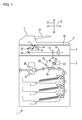
FIG. 1 is a schematic diagram of an internal configuration of an image processing apparatus according to one embodiment of the present disclosure. -
FIG. 2 is a block diagram illustrating an exemplary electrical configuration of the image processing apparatus. -
FIG. 3 illustrates a characteristic portion of the image processing apparatus. -
FIG. 4 illustrates a manner in which a sheet detection sensor is disposed. -
FIG. 5 is a graph showing a two-dimensional coordinate system in which a first detection distance and a second detection distance are variables, and combinations of reference values for the first detection distance and reference values for the second detection distance. -
FIG. 6 is a flow chart showing a process performed by a control portion in an inspection mode. -
FIG. 7 illustrates a modification of the embodiment according to the present disclosure. - Hereinafter, an embodiment of the present disclosure will be described with reference to the drawings. The embodiment described below represents an exemplary implementation of the present disclosure, and the technical scope of the present disclosure is not limited by the embodiment described below.
- Initially, with reference to
FIG. 1 andFIG. 2 , a schematic configuration of animage processing apparatus 1 according to an embodiment of the present disclosure will be described. Theimage processing apparatus 1 is a multifunction peripheral that includes an image reading function, a facsimile function, an image forming function, and the like. As shown inFIG. 1 , theimage processing apparatus 1 includes animage reading portion 2, adocument cover 3, an automatic document feeding device (Auto Document Feeder; hereinafter, referred to as an ADF) 4, animage forming portion 5, an operation display portion 6 (seeFIG. 2 ), asheet feed cassette 7, a communication interface (I/F) portion 8 (seeFIG. 2 ), and a control portion 9 (seeFIG. 2 ) that controls the above components. As an exemplary image processing apparatus of the present disclosure, theimage processing apparatus 1 that is a multifunction peripheral will be described. However, the image processing apparatus of the present disclosure is not limited thereto, and may be implemented as, for example, a printer, a facsimile device, a copying machine, or a scanner device. - The
image reading portion 2 executes an image reading process for reading image data from a document. As shown inFIG. 1 , theimage reading portion 2 includes a contact glass 10 (glass plate), areading unit 11,mirrors optical lens 14, a Charge Coupled Device (CCD) 15, and the like. - The
reading unit 11 includes anLED light source 16 and amirror 17, and can be moved in a sub-scanning direction 18 (the left-right direction inFIG. 1 ) by a movement mechanism (not shown) using a driving motor such as a stepping motor. When thereading unit 11 is moved in thesub-scanning direction 18 by the driving motor, light applied from theLED light source 16 toward thecontact glass 10 provided on the upper surface of theimage reading portion 2 is scanned in thesub-scanning direction 18. - When light is applied from the
LED light source 16, themirror 17 reflects, toward themirror 12, light reflected by a document or a rear surface of thedocument cover 3. The light reflected by themirror 17 is guided to theoptical lens 14 through themirrors optical lens 14 focuses the incident light on theCCD 15. - The
CCD 15 is a photoelectric converter that converts the received light into an electric signal (voltage) according to an amount of the received light (intensity of brightness), to output the electric signal to thecontrol portion 9. Thecontrol portion 9 generates image data of a document by subjecting the electric signal from theCCD 15 to image processing. In the present embodiment, an exemplary case where theCCD 15 is used as an imaging device is described. However, instead of the reading mechanism using theCCD 15, a reading mechanism that includes a contact image sensor (CIS) having a focal length shorter than theCCD 15 may be used. - To the
image reading portion 2, thedocument cover 3 is pivotably mounted. By thedocument cover 3 being operated to pivot, thecontact glass 10 on the upper surface of theimage reading portion 2 is opened or closed. In a pivoting support portion of thedocument cover 3, a cover-opening detection sensor (not shown) such as a limit switch is provided. When a user opens thedocument cover 3 such that an image of a document is read, the cover-opening detection sensor is actuated to output a detection signal (cover-opening detection signal) to thecontrol portion 9. - The
image reading portion 2 reads an image of a document in the following procedure. Firstly, the document is placed on thecontact glass 10, and thedocument cover 3 is then put into a closed position. Thereafter, when an image reading instruction is inputted through theoperation display portion 6, one line of light is sequentially applied continuously from the LEDlight source 16 while thereading unit 11 is being moved rightward in thesub-scanning direction 18. Light reflected by the document or the rear surface of thedocument cover 3 is guided to theCCD 15 through themirrors optical lens 14, and light amount data based on an amount of light received by theCCD 15 is sequentially outputted to thecontrol portion 9. When light amount data for the entirety of the area to which light has been applied is obtained, thecontrol portion 9 processes the light amount data, to generate image data of the document based on the light amount data. - The
ADF 4 is provided in thedocument cover 3. TheADF 4 sequentially feeds documents set on a document setportion 19, by means of a plurality of feed rollers, and moves the document rightward in thesub-scanning direction 18 through an automatic document reading position defined on thecontact glass 10. When the document is moved by theADF 4, thereading unit 11 is positioned below the automatic document reading position, and an image of the document being moved is read by thereading unit 11 at this position. - As shown in
FIG. 1 , theimage forming portion 5 executes an image forming process (printing process) by electrophotography. Theimage forming portion 5 executes the image forming process according to image data read by theimage reading portion 2 or a printing job inputted through the communication I/F portion 8 from an external information processing apparatus such as a personal computer. Specifically, theimage forming portion 5 includes aphotosensitive drum 20, a chargingportion 21, a developingportion 22, atoner container 23, atransfer roller 24, anelectricity removing portion 25, a fixingroller 26, apressure roller 27, and the like. In the present embodiment, theimage forming portion 5 using electrophotography, is illustrated. However, theimage forming portion 5 is not limited to an image forming portion using electrophotography, and may be an image forming portion using an inkjet recording mode, or an image forming portion using another recording mode or printing mode. - In the
image forming portion 5, an image forming process on a print sheet fed from thesheet feed cassette 7 is performed in the following procedure. Firstly, when a printing job including a print instruction is inputted through the communication I/F portion 8, thephotosensitive drum 20 is uniformly charged at a predetermined potential by the chargingportion 21. Subsequently, light based on image data included in the printing job is applied to the surface of thephotosensitive drum 20 by a laser scanner unit (not shown). Thus, an electrostatic latent image is formed on the surface of thephotosensitive drum 20. The electrostatic latent image on thephotosensitive drum 20 is developed (visualized) into a toner image by the developingportion 22. Toner (developer) is additionally supplied to the developingportion 22 from thetoner container 23. Subsequently, the toner image formed on thephotosensitive drum 20 is transferred to the print sheet by thetransfer roller 24. Thereafter, the toner image having been transferred to the print sheet is heated and fused by the fixingroller 26, to be fixed onto the print sheet, when the print sheet passes between the fixingroller 26 and thepressure roller 27 and is discharged. Potential of thephotosensitive drum 20 is removed by theelectricity removing portion 25. - In
FIG. 2 , the communication I/F portion 8 is an interface that executes data communication with an external device connected to theimage processing apparatus 1 via a communication network such as the Internet or a LAN. Astorage portion 28 is implemented as a non-volatile memory such as a hard disk drive. In thestorage portion 28, an inspection table 100 described below is previously stored. - The
operation display portion 6 includes adisplay portion 29 and anoperation portion 30. Thedisplay portion 29 is implemented as, for example, a color liquid crystal display, and displays various information to a user that operates theoperation display portion 6. Theoperation portion 30 is implemented as various push button keys disposed adjacent to thedisplay portion 29, a touch panel sensor disposed on a display screen of thedisplay portion 29, and the like. To theoperation portion 30, various instructions are inputted by a user of theimage processing apparatus 1. - The
image reading portion 2 includes asheet detection device 31. As shown inFIG. 3 , thesheet detection device 31 includes asheet detection unit 32, asupport portion 33, and an ascending and descending drivingportion 34. Thesheet detection unit 32 is an example of a sheet detection portion. Thesheet detection unit 32 is mounted at a predetermined position below thecontact glass 10 on which a document is placed, and detects a sheet in a predetermined detection area. Thesheet detection unit 32 will be described below in detail. The ascending and descending drivingportion 34 is an example of a driving portion of the present disclosure. - The
support portion 33 supports thesheet detection unit 32 such that thesheet detection unit 32 is movable in an approaching direction and a retreating direction relative to a sheet placed on thecontact glass 10. Thesupport portion 33 includes a support base 47 (seeFIG. 4 ) on which thesheet detection unit 32 is mounted, and arack member 35 that is a component of a rack andpinion mechanism 36. Thesheet detection unit 32 is fixed to and supported by thesupport base 47. Thesupport base 47 is connected to therack member 35 that extends in a normal direction 37 (the up-down direction of theimage processing apparatus 1; seeFIG. 1 ) that is normal to thecontact glass 10. - The ascending and descending driving
portion 34 includes: a drivingmotor 38 such as a stepping motor; apinion member 39 that is a component of the rack andpinion mechanism 36; and a rotationamount detection portion 40. The drivingmotor 38 is a motor that can be driven to rotate in two directions, that is, forward and backward, and drives rotation of thepinion member 39. Thepinion member 39 meshes with therack member 35. Drive force from the drivingmotor 38 is transmitted to thesupport base 47 of thesupport portion 33 through the rack andpinion mechanism 36 including thepinion member 39 and therack member 35. - When drive current is supplied to the driving
motor 38, the drivingmotor 38 generates drive force. Thepinion member 39 rotates due to the drive force. When thepinion member 39 rotates, therack member 35 that meshes with thepinion member 39 moves upward or downward relative to theimage processing apparatus 1. Since thesupport base 47 is connected to therack member 35, thesupport base 47 also slides upward or downward. Therefore, thesheet detection unit 32 fixed to thesupport base 47 slides upward or downward (ascends or descends). That is, the ascending and descending drivingportion 34 moves thesheet detection unit 32 in the approaching direction and the retreating direction relative to thecontact glass 10 and a sheet placed on thecontact glass 10. - The rotation
amount detection portion 40 is implemented as, for example, a well-known rotary encoder, and detects a rotation amount of a drive shaft (not shown) of the drivingmotor 38. An output signal from the rotationamount detection portion 40 is used for detecting a distance between the sheet and the sheet detection unit 32 (alight emitter 45 described below), specifically, a distance in the direction normal to thecontact glass 10, as described below. In the following description, the distance between the sheet and thesheet detection unit 32 represents a distance in the direction normal to thecontact glass 10. - The
sheet detection unit 32 includes asheet detection sensor 41, a drivingcircuit 42, anamplifier 43, and acomparator 44. - The
sheet detection sensor 41 is a reflective optical sensor that includes thelight emitter 45 that has, for example, a light emitting diode, and alight receiver 46 that has, for example, a phototransistor. As shown inFIG. 4 , thesheet detection sensor 41 is mounted below thecontact glass 10 having a surface (upper surface) on which a document is placed. Therefore, thesheet detection sensor 41 detects a sheet through thecontact glass 10. That is, thelight emitter 45 of thesheet detection sensor 41 applies light to a sheet in the detection area through thecontact glass 10. Thelight receiver 46 receives, through thecontact glass 10, light reflected by the sheet due to the light application. An amount of received light in thelight receiver 46 depends on a distance to the sheet. Further, the amount of received light also depends on an image density in the sheet. Thelight receiver 46 outputs a signal according to an amount of received light. An output signal from thelight receiver 46 becomes an output signal from thesheet detection sensor 41. When no sheet is in the detection area, no reflected light is received by thelight receiver 46. Therefore, an output from thesheet detection sensor 41 represents zero. - The driving
circuit 42 generates current to be supplied to thelight emitter 45 of thesheet detection sensor 41 based on power supplied from a power supply (not shown), and supplies the generated current to thelight emitter 45. The drivingcircuit 42 is able to vary a magnitude of current to be generated, according to a control signal from asecond control portion 52 of thecontrol portion 9. Thelight emitter 45 emits light with an amount of light emission based on the magnitude of the current supplied from the drivingcircuit 42. That is, an amount of light emission from thelight emitter 45 can be controlled by thecontrol portion 9. - The
amplifier 43 amplifies the output signal outputted by thelight receiver 46 with a predetermined amplification factor. Thecomparator 44 compares the output signal outputted by theamplifier 43, with a predetermined threshold value, and outputs a signal representing the comparison result. That is, when the output signal from theamplifier 43 is higher than the threshold value, thecomparator 44 outputs a HIGH signal. When the output signal from theamplifier 43 is lower than the threshold value, thecomparator 44 outputs a LOW signal. The output signal representing the comparison result is outputted to thecontrol portion 9. As described below, a sheetdetection processing portion 50 of thecontrol portion 9 determines whether or not a sheet is in the detection area, based on the output signal outputted by thecomparator 44. - The
control portion 9 includes a Central Processing Unit (CPU), a Read Only Memory(ROM), and a Random Access Memory (RAM). The CPU is a processor that executes various calculation processes. The ROM is a non-volatile storage portion in which information such as control programs for causing the CPU to execute various processes is previously stored. The RAM is a volatile storage portion which is used as a temporary storage memory (work area) for various processes executed by the CPU. Thecontrol portion 9 controls operations of various components by the CPU executing the programs stored in the ROM. - In the
image processing apparatus 1, theimage reading portion 2, theimage forming portion 5, theoperation display portion 6, the communication I/F portion 8, thestorage portion 28, and thecontrol portion 9 are connected to each other via adata bus 48 so as to perform data input and output among the components. - The
operation portion 30 includes an inspection mode setting operation portion 49 (seeFIG. 2 ) that allows an operator to perform an operation for setting theimage processing apparatus 1 so as to be in an inspection mode described below. The inspection mode is a mode in which whether or not an output from thesheet detection unit 32 is correct, is determined in an inspection, and when the output is not correct, the output is corrected. - In the present embodiment, in order to determine in the inspection whether or not an output from the
sheet detection sensor 41 is correct, two kinds of reference sheets having different image densities are used. The two kinds of reference sheets are referred to as a first reference sheet and a second reference sheet. Image densities in the first reference sheet and the second reference sheet, respectively, are predefined. In the inspection, the reference sheets are placed on thecontact glass 10 one by one. - When a mode setting operation is performed, for setting of the inspection mode, by the inspection mode
setting operation portion 49, thecontrol portion 9 sets theimage processing apparatus 1 so as to be in the inspection mode. Theimage processing apparatus 1 in the inspection mode corresponds to an inspection apparatus of the present disclosure. Thecontrol portion 9 includes the sheetdetection processing portion 50, afirst control portion 51, thesecond control portion 52, adistance detection portion 53, and adetermination portion 54, which are associated with the inspection mode. - The sheet
detection processing portion 50 performs a document detection process for determining whether or not a document is in the detection area, based on the output signal outputted by thecomparator 44. That is, the sheetdetection processing portion 50 determines that a sheet is in the detection area, when receiving a HIGH signal from thecomparator 44. The sheetdetection processing portion 50 determines that no sheet is in the detection area, when receiving a LOW signal from thecomparator 44. - The
first control portion 51 controls the drivingmotor 38 mounted to the ascending and descending drivingportion 34, to change a distance between a sheet and thesheet detection sensor 41 by means of the ascending and descending drivingportion 34. That is, thefirst control portion 51 changes a driving direction of rotation of the drivingmotor 38, to change moving directions in which thesupport portion 33 and thesheet detection sensor 41 are moved. Thefirst control portion 51 rotates the drivingmotor 38 forward, whereby thesupport portion 33 and thesheet detection sensor 41 can be moved upward. On the other hand, thefirst control portion 51 rotates the drivingmotor 38 backward, whereby thesupport portion 33 and thesheet detection sensor 41 can be moved downward. - A predetermined position in a range in which the
sheet detection sensor 41 is movable, is set to a home position of thesheet detection sensor 41 in the inspection. For the inspection, thefirst control portion 51 controls the drivingmotor 38 to position thesheet detection sensor 41 at the home position. Thefirst control portion 51 performs a movement control so as to move thesheet detection sensor 41 upward from the home position with a predetermined movement pitch until the sheetdetection processing portion 50 detects the presence of a document. Further, when thedetermination portion 54 determines that an output from thesheet detection unit 32 is not correct as described below, thefirst control portion 51 returns thesheet detection sensor 41 to the home position and then performs the movement control. As described below, each time the movement control is repeatedly performed, an amount of light emission from thelight emitter 45 is changed. - The
second control portion 52 controls the drivingcircuit 42 to control an operation performed by thelight emitter 45 in thesheet detection sensor 41. That is, thesecond control portion 52 controls current to be supplied from the drivingcircuit 42 to thelight emitter 45, to switch a light emitting operation of thelight emitter 45 between on and off, or change an amount of light emission from thelight emitter 45. - The
distance detection portion 53 detects a distance 70 (seeFIG. 4 ) between thesheet detection sensor 41, and each of the first reference sheet and the second reference sheet placed on thecontact glass 10. Thedistance detection portion 53 obtains, from the rotationamount detection portion 40, information about an amount of rotation of thepinion member 39. A relationship between the amount of rotation of thepinion member 39 and a moving distance of thesheet detection sensor 41 is predefined. Further, a distance between the home position and the reference sheet placed on thecontact glass 10 is previously stored in thestorage portion 28. Therefore, by a moving distance of thesheet detection sensor 41 from the home position being detected, a distance between thesheet detection sensor 41 and the reference sheet can be detected. When the first reference sheet is detected, a detection distance detected by thedistance detection portion 53 is referred to as a first detection distance. When the second reference sheet is detected, a detection distance detected by thedistance detection portion 53 is referred to as a second detection distance. - The ascending and descending driving
portion 34 is controlled by thefirst control portion 51, and light emission from thelight emitter 45 is controlled by thesecond control portion 52. Thus, as described below, while a distance between the first reference sheet and thesheet detection sensor 41 is being changed, an operation for detecting for the first reference sheet is performed by thesheet detection unit 32. Thedistance detection portion 53 detects the first detection distance when the sheetdetection processing portion 50 determines that a document is in the detection area. Thedetermination portion 54 determines whether or not the first detection distance is equal to a predetermined first reference value. - The
distance detection portion 53 similarly performs, for the second reference sheet, a series of processes as performed for the first reference sheet. That is, thedistance detection portion 53 operates to control thefirst control portion 51 and thesecond control portion 52 such that, while a distance between the second reference sheet and thesheet detection sensor 41 is being changed, an operation for detecting for the second reference sheet is performed by thesheet detection unit 32. Thedistance detection portion 53 detects the second detection distance when the sheetdetection processing portion 50 determines that a document is in the detection area. Thedetermination portion 54 determines whether or not the second detection distance is equal to a predetermined second reference value. - In the present embodiment, the first reference value and the second reference value indicate distances represented by coordinates on a predetermined
straight line 80 in a two-dimensional coordinate system in which the first detection distance and the second detection distance are variables, as shown inFIG. 5 . As shown inFIG. 2 , an inspection table 100 representing combinations of reference values for the first detection distance and reference values for the second detection distance, which correspond to coordinates on thestraight line 80, is previously stored in thestorage portion 28. - The
determination portion 54 determines whether or not the combination of the first detection distance and the second detection distance is predefined in the inspection table 100. In other words, thedetermination portion 54 determines whether or not a coordinate point corresponding to the combination of the first detection distance and the second detection distance detected by thedistance detection portion 53 represents a coordinate on thestraight line 80. When thedetermination portion 54 determines that the combination of the first detection distance and the second detection distance is defined in the inspection table 100 (a coordinate point corresponding to the combination of the first detection distance and the second detection distance represents a coordinate on the straight line 80), it is determined that the output from thesheet detection unit 32 is correct. When thedetermination portion 54 determines that the combination of the first detection distance and the second detection distance is not defined in the inspection table 100 (a coordinate point corresponding to the combination of the first detection distance and the second detection distance does not represent a coordinate on the straight line 80), it is determined that the output from thesheet detection unit 32 is not correct.FIG. 5 illustrates an example of a coordinatepoint 400 obtained when thedetermination portion 54 determines that the output from thesheet detection unit 32 is not correct. In the present embodiment, although the reference values for the first detection distance and the second detection distance correspond to coordinate points on thestraight line 80, predetermined allowable errors may be set for the reference values. That is, reference values corresponding to coordinate points in a predetermined area 81 (seeFIG. 5 ) including thestraight line 80 in the two-dimensional coordinate system may be used as the reference values for the first detection distance and the second detection distance. - When the
determination portion 54 determines that the output from thesheet detection unit 32 is not correct, thesecond control portion 52 changes an amount of light emission from thelight emitter 45. In the present embodiment, thesecond control portion 52 can change current to be supplied to thelight emitter 45 by the drivingcircuit 42, stepwise by a predetermined amount. Therefore, an amount of light emission from thelight emitter 45 can be changed stepwise. Each time thedetermination portion 54 determines that the output from thesheet detection unit 32 is not correct, thesecond control portion 52 increases an amount of light emission from thelight emitter 45 by one step. When thedetermination portion 54 determines that the output from thesheet detection unit 32 is correct, thesecond control portion 52 stops controlling the amount of light emission, and sets the amount of light emission obtained at that time, as an amount of light emission in a normal state (for detecting a document). As described above, in the present embodiment, only when both the first detection distance and the second detection distance represent the reference values, the amount of light emission in a normal state (for detecting a document) is set. - In the
sheet detection sensor 41, even when image densities of documents are the same, or even when distances to the documents are the same, outputs from thesheet detection sensor 41 may be different due to an error. The causes for such a difference due to an error may be various. One of the causes, in a configuration in which thecontact glass 10 on which a document is placed is disposed between thesheet detection sensor 41 and the document, is a variation among products due to error in manufacturing thecontact glasses 10. That is, in a case where a light transmittance or refractive index is different among thecontact glasses 10 due to variation among proudcts as thecontact glasses 10, even if the detection operation is performed for documents having the same image density in a state where distances to the documents are the same, amounts of received light in thesheet detection sensor 41 are different. As a result, error in output occurs. In general, thesheet detection sensors 41 are produced on the assumption that thecontact glasses 10 as products have the same light transmittance or refractive index. Thesheet detection sensors 41 are not produced in consideration of a light transmittance or refractive index being different among thecontact glasses 10 due to variation among products as thecontact glasses 10. Therefore, outputs from thesheet detection sensors 41 may vary individually depending on the products. - Such an error in output may cause erroneous detection for a document. That is, in a configuration where a document is detected by determining that the document is present when an output from the
sheet detection sensor 41 is greater than a predetermined threshold value, in a case where the output from thesheet detection sensor 41 is less than the predetermined threshold value due to the error, it may be erroneously determined that the document is not in the detection area although the document is actually in the detection area. - In the
image processing apparatus 1 of the present embodiment, by thecontrol portion 9 performing the process described below, erroneous detection for the document due to error in output from thesheet detection sensor 41 can be prevented or reduced. - Next, a process performed by the
control portion 9 in the inspection mode will be described.FIG. 6 is a flow chart showing a process performed by thecontrol portion 9 in the inspection mode. When the inspection modesetting operation portion 49 is operated, thecontrol portion 9 executes the process to be performed by thecontrol portion 9 in the inspection mode. In the flow chart ofFIG. 6 , step S1, S2, ··· represent process procedure (step) numbers. The process performed by thecontrol portion 9 in the inspection mode is for implementing an inspection method according to the present disclosure. - As shown in
FIG. 6 , when the inspection modesetting operation portion 49 is operated, thecontrol portion 9 causes thedisplay portion 29 to display a message representing an instruction for placing the first reference sheet on the contact glass 10 (step S1). Further, thecontrol portion 9 performs initialization for the inspection (step S2). In the initialization, for example, thefirst control portion 51 moves thesheet detection sensor 41 to the home position, and thesecond control portion 52 sets an amount of light emission from thelight emitter 45 of thesheet detection sensor 41 as a minimum value in a predetermined light emission amount range. Thecontrol portion 9 waits for reception of an inspection start instruction signal inputted by an operator (NO in step S3). - In the
control portion 9, when the inspection start instruction signal is received (YES in step S3), thesecond control portion 52 causes thelight emitter 45 to emit light with a minimum amount of light emission, and the sheetdetection processing portion 50 determines whether or not the first reference sheet is in the detection area, based on a signal outputted by the comparator 44 (step S4). As a result of the determination, when the sheetdetection processing portion 50 determines that the first reference sheet is not in the detection area (NO in step S5), thefirst control portion 51 moves thesheet detection sensor 41 upward by the movement pitch (step S6), and the process is then returned to step S4. - When the sheet
detection processing portion 50 determines in step S5 that the first reference sheet is in the detection area (YES in step S5), thecontrol portion 9 detects the present distance (the first detection distance) between thesheet detection sensor 41 and the first reference sheet, and stores the distance in a register (not shown) of the CPU (step S7). The process step of step S7 includes a process of a first step of the present disclosure. - After step S7, the
control portion 9 causes thedisplay portion 29 to display a message representing an instruction for placing the second reference sheet on the contact glass 10 (step S8). Further, thecontrol portion 9 performs the initialization (step S9). Thecontrol portion 9 waits for reception of the inspection start instruction signal (NO in step S10). - When the
control portion 9 receives the inspection start instruction signal (YES in step S10), thecontrol portion 9 performs the same process steps as steps S4 to S7. That is, thesecond control portion 52 causes thelight emitter 45 to emit light with a minimum amount of light emission, and the sheetdetection processing portion 50 determines whether or not the second reference sheet is in the detection area, based on the output signal outputted by the comparator 44 (step S11). As a result of the determination, when the sheetdetection processing portion 50 determines that the second reference sheet is not in the detection area (NO in step S12), thefirst control portion 51 moves thesheet detection sensor 41 upward by the movement pitch (step S13), and the process is then returned to step S11. - When the sheet
detection processing portion 50 determines in step S12 that the second reference sheet is in the detection area (YES in step S12), thecontrol portion 9 detects the present distance (the second detection distance) between thesheet detection sensor 41 and the second reference sheet, and stores the distance in the register of the CPU (step S14). The process step of step S14 includes a process of the first step of the present disclosure. - The
determination portion 54 determines whether or not both the first detection distance and the second detection distance stored in the register of the CPU represent the reference values (whether or not a combination of the first detection distance and the second detection distance is defined in the inspection table 100) (step S15). The process step of step S15 corresponds to a process of a second step of the present disclosure. As a result, when thedetermination portion 54 determines that at least one of the first detection distance and the second detection distance does not represent the reference value (NO in step S15), it is determined that the output from thesheet detection sensor 41 is not correct (step S16). In response to the determination result, thesecond control portion 52 increases an amount of light emission from thelight emitter 45 by one step (step S17), and thecontrol portion 9 then returns the process to step S1. The process step of step S17 corresponds to a process of a third step of the present disclosure. - When the
determination portion 54 determines that both the first detection distance and the second detection distance represent the reference values (YES in step S15), it is determined that the output from thesheet detection sensor 41 is correct (step S18). In response to the determination result, thesecond control portion 52 sets the present amount of light emission from thelight emitter 45, as an amount of light emission for a document detection process, and thecontrol portion 9 ends the process in the inspection mode. - As described above, in the present embodiment, while a distance between the reference sheet and the
sheet detection sensor 41 is being changed, thesheet detection sensor 41 performs the detection operation, to detect a distance at which the output from thesheet detection sensor 41 represents the threshold value. Whether or not the detected distance is equal to the predetermined reference value is determined. When the distance is determined as being unequal to the predetermined reference value, an amount of light emission from thelight emitter 45 of thesheet detection sensor 41 is increased. A series of process steps described above is repeated until the detection distance at which the output from thesheet detection sensor 41 represents the threshold value, becomes equal to the reference value. - Thus, error generated in the output from the
sheet detection sensor 41 is eliminated or reduced, to correct the output. As a result, a document can be assuredly detected. - A document having an image density that is greatly different from that of the reference sheet used for the inspection, may be placed on the
contact glass 10. It is assumed that only one kind of reference sheet is used for the inspection. At this time, in a case where thesheet detection sensor 41 and the document are distant from each other over a distance to the reference sheet having been set in the inspection, and light is emitted by thelight emitter 45 with an amount of light emission having been set in the inspection, a signal having a value different from the threshold value may be outputted by thesheet detection sensor 41. - On the other hand, in the present embodiment, two kinds of reference sheets (the first reference sheet and the second reference sheet) that are different in image density are used to perform the inspection. Therefore, as compared to a case where only one kind of reference sheet is used to perform the inspection, the output from the
sheet detection sensor 41 can be made correct also for documents with different image densities. As a result, documents with different image densities can be assuredly detected. However, the present disclosure is also applicable to a case where one kind of reference sheet is used to perform the inspection. In a case where only one kind of reference sheet is used to perform the inspection, one reference value for a distance between the reference sheet and thesheet detection sensor 41 is used, and the reference value is stored in thestorage portion 28. The same process steps as for the above embodiment are performed except that steps S8 to S14 in the flow chart shown inFIG. 6 are omitted, and whether or not the detection distance between the reference sheet and thesheet detection sensor 41 as obtained when the reference sheet is determined as being in the detection area, is equal to the reference value, is determined in step S15. - In a case where three or more kinds of reference sheets are used, the output from the
sheet detection sensor 41 can be made correct also when variation in image density among documents is increased. As a result, documents with various image densities can be more assuredly detected. - In the present embodiment, the inspection is performed for the
sheet detection sensor 41 that detects a document thruogh thecontact glass 10. Therefore, an output from thesheet detection sensor 41 can be corrected even when variation among products as thecontact glasses 10 occurs or there is stain or the like as well as the characteristics of thesheet detection sensor 41 itself change with the passage of time. - A preferred embodiment of the present disclosure has been described above. However, the present disclosure is not limited to the contents described above. Various modifications can be made.
- The inspection as described above may be performed when the
image processing apparatus 1 is being manufactured as well as after the product has been delivered. Thus, variation, among theimage processing apparatuses 1, in document detection accuracy of thesheet detection unit 32, can be eliminated or reduced. - Further, in the above embodiment, the inspection is performed for the sensor for detecting documents. However, a subject to be detected by the sensor is not limited to a document. A subject to be detected may be sheets in general, such as a print sheet in an unprinted state or a print sheet in a printed state.
- Further, in the above embodiment, the inspection is performed for the
sheet detection sensor 41 that detects presence or absence of a document on thecontact glass 10. However, a subject to be inspected is not limited to thesheet detection sensor 41. For example, in a case where whether or not a sheet is in a tray (not shown) is determiend by using the reflective optical sensor, in a case where the reflective optical sensor detects for a document set in the document setportion 19, or in a case where the reflective optical sensor detects for a given or greater number of print sheets in thesheet feed cassette 7, the inspection may be performed for such a sensor in the inspection method of the present disclosure. - Further, in some cases, the image processing apparatus includes, at a predetermined position upstream of the image forming portion, a registration roller for conveying a print sheet to the image forming portion, and a registration sensor for detecting arrival of the print sheet at the registration roller and passing of the print sheet through the registration roller. The registration roller allows the print sheet to be conveyed to the image forming portion according to a time when the image forming operation is performed by the image forming portion. In such an image processing apparatus, the inspection may be performed for the registration sensor in the inspection method of the present disclosure. Further, the inspection may be performed for not only a sensor that detects for sheets that are stationary but also a sensor that detects for sheets which are being conveyed.
- In the above embodiment, the
image processing apparatus 1 has the inspection function as described above. However, the present disclosure includes an embodiment where a device which is separate from theimage processing apparatus 1 causes theimage processing apparatus 1 to perform the inspection as described above, as shown inFIG. 7 . InFIG. 7 , acontrol device 200 is shown as the separate device that causes theimage processing apparatus 1 to perform the inspection as described above. Thecontrol device 200 can perform wired or wireless communication with theimage processing apparatus 1. Further, thecontrol device 200 includes acontrol portion 140, and thecontrol portion 140 includes a sheetdetection processing portion 150, afirst control portion 151, asecond control portion 152, adistance detection portion 153, and adetermination portion 154 which are similar to thecomponents 50 to 54, respectively, of the above embodiment. Theimage processing apparatus 1 is remotely operated to perform the inspection by thesecomponents 150 to 154. Also in such a configuration, the same effect as in the above embodiment can be obtained. - It is to be understood that the embodiments herein are illustrative and not restrictive, since the scope of the disclosure is defined by the appended claims rather than by the description preceding them, and all changes that fall within metes and bounds of the claims, or equivalence of such metes and bounds thereof are therefore intended to be embraced by the claims.
Claims (6)
- An inspection method for a sheet detection device (31), for inspecting the sheet detection device (31) that determines whether or not a sheet is in a detection area based on comparison between an output from a reflective optical sensor (41) that outputs a signal according to an image density of the sheet to be detected and a distance to the sheet, and a predetermined threshold value, the inspection method comprising:a first step (S7) of causing the sheet detection device (31) to perform a detection operation for a reference sheet while changing a distance between the reflective optical sensor (41) and the reference sheet having a predetermined image density, and detecting a distance between the reflective optical sensor (41) and the reference sheet when a sheet detection signal indicating that the reference sheet is detected is outputted by the sheet detection device (31);a second step (S15) of determining whether or not a detection distance detected in the first step (S7) is equal to a predetermined reference value; anda third step (S17) of changing an amount of light emission from a light emitter (45) in the reflective optical sensor (41) when the detection distance detected in the first step (S7) is determined, in the second step (S15), as being unequal to the reference value, whereinthe first step (S7), the second step (S15), and the third step (S17) are repeated until the detection distance detected in the first step (S7) is determined, in the second step (S15), as being equal to the reference value.
- The inspection method for the sheet detection device (31) according to claim 1, wherein
the reference sheet includes a first reference sheet and a second reference sheet that have different image densities, respectively,
the first, the second, and the third steps(S7,S15,S17) are performed for the first reference sheet and the second reference sheet, and
the reference value indicates a distance represented by a coordinate on a predetermined straight line in a two-dimensional coordinate system in which a detection distance detected for the first reference sheet and a detection distance detected for the second reference sheet are variables, and
whether or not a coordinate point corresponding to a combination of the detection distance, for the first reference sheet, detected in the first step (S7) and the detection distance, for the second reference sheet, detected in the first step (S7), represents the coordinate on the straight line, is determined in the second step (S15). - A sheet detection device (31) comprising:a sheet detection portion (32) configured to determine whether or not a sheet is in a detection area, based on comparison between an output from a reflective optical sensor (41) that outputs a signal according to an image density of the sheet to be detected and a distance to the sheet, and a predetermined threshold value;a support portion configured to support the reflective optical sensor (41) such that the reflective optical sensor (41) is movable in an approaching direction and a retreating direction relative to the sheet;a driving portion (34) configured to drive the reflective optical sensor (41) in the approaching direction and the retreating direction;a first control portion (51, 151) configured to cause the driving portion (34) to change a distance between the sheet and the reflective optical sensor (41);a second control portion (52, 152) configured to control an amount of light emission from a light emitter (45) in the reflective optical sensor (41);a distance detection portion (53, 153) configured to operate such that, according to control by the first control portion (51, 151) and the second control portion (52, 152), the sheet detection portion (32) performs a detection operation for a reference sheet while changing a distance between the reflective optical sensor (41) and the reference sheet having a predetermined image density, and to detect a distance between the reflective optical sensor (41) and the reference sheet when a sheet detection signal indicating that the reference sheet is detected is outputted by the sheet detection portion (32); anda determination portion (54, 154) configured to determine whether or not a detection distance detected by the distance detection portion (53, 153) is equal to a predetermined reference value, whereinthe second control portion (52, 152) changes an amount of light emission from the light emitter (45) when the determination portion (54, 154) determines that the detection distance detected by the distance detection portion (53, 153) is unequal to the reference value, and repeatedly changes an amount of light emission until the determination portion (54, 154) determines that the detection distance detected by the distance detection portion (53, 153) is equal to the reference value.
- The sheet detection device (31) according to claim 3, wherein
the reference sheet includes a first reference sheet and a second reference sheet that have different image densities, respectively,
the distance detection portion and the determination portion perform operations, respectively, for the first reference sheet and the second reference sheet,
the reference value indicates a distance represented by a coordinate on a predetermined straight line in a two-dimensional coordinate system in which a detection distance detected for the first reference sheet and a detection distance detected for the second reference sheet are variables, and
the determination portion (54, 154) determines whether or not a coordinate point corresponding to a combination of the detection distance, for the first reference sheet, detected by the distance detection portion (53, 153), and the detection distance, for the second reference sheet, detected by the distance detection portion (53, 153), represents the coordinate on the straight line. - The sheet detection device (31) according to claim 3 or 4, wherein
the sheet and the reference sheet are conveyed or placed on a surface of a glass plate (10), and
the reflective optical sensor (41) detects the sheet and the reference sheet on a rear surface side of the glass plate (10). - An inspection apparatus (1) capable of communicating with a sheet detection device (31) that includes: a reflective optical sensor (41) that outputs a signal according to an image density of a sheet to be detected, and a distance to the sheet; a support portion that supports the reflective optical sensor (41) such that the reflective optical sensor (41) is movable in an approaching direction and a retreating direction relative to the sheet; and a driving portion (34) that drives the reflective optical sensor (41) in the approaching direction and the retreating direction, and that determines whether or not the sheet is in a detection area, based on comparison between an output from the reflective optical sensor (41) and a predetermined threshold value, the inspection apparatus (1) inspecting the sheet detection device (31), the inspection apparatus (1) comprising:a first control portion (51, 151) configured to cause the driving portion (34) to change a distance between the sheet and the reflective optical sensor (41);a second control portion (52, 152) configured to control an amount of light emission from a light emitter (45) in the reflective optical sensor (41);a distance detection portion (53, 153) configured to operate such that, according to control by the first control portion (51, 151) and the second control portion (52, 152), the sheet detection device (31) performs a detection operation for a reference sheet while changing a distance between the reflective optical sensor (41) and the reference sheet having a predetermined image density, and to detect a distance between the reflective optical sensor (41) and the reference sheet when a sheet detection signal indicating that the reference sheet is detected is outputted by the sheet detection device (31); anda determination portion (54, 154) configured to determine whether or not a detection distance detected by the distance detection portion (53, 153) is equal to a predetermined reference value, whereinthe second control portion (52, 152) changes an amount of light emission from the light emitter (45) when the determination portion (54, 154) determines that the detection distance detected by the distance detection portion (53, 153) is unequal to the reference value, and repeatedly changes an amount of light emission until the determination portion (54, 154) determines that the detection distance detected by the distance detection portion (53, 153) is equal to the reference value.
Applications Claiming Priority (1)
| Application Number | Priority Date | Filing Date | Title |
|---|---|---|---|
| JP2014066771A JP5968353B2 (en) | 2014-03-27 | 2014-03-27 | Inspection method for sheet detection apparatus, sheet detection apparatus, image processing apparatus, and inspection apparatus |
Publications (2)
| Publication Number | Publication Date |
|---|---|
| EP2924509A1 true EP2924509A1 (en) | 2015-09-30 |
| EP2924509B1 EP2924509B1 (en) | 2019-05-22 |
Family
ID=53039186
Family Applications (1)
| Application Number | Title | Priority Date | Filing Date |
|---|---|---|---|
| EP15160810.6A Active EP2924509B1 (en) | 2014-03-27 | 2015-03-25 | Inspection method for sheet detection device, sheet detection device, and inspection apparatus |
Country Status (4)
| Country | Link |
|---|---|
| US (1) | US9506747B2 (en) |
| EP (1) | EP2924509B1 (en) |
| JP (1) | JP5968353B2 (en) |
| CN (1) | CN104950347B (en) |
Families Citing this family (4)
| Publication number | Priority date | Publication date | Assignee | Title |
|---|---|---|---|---|
| JP6630137B2 (en) * | 2015-11-30 | 2020-01-15 | 理想科学工業株式会社 | Image reading device |
| JP6659155B2 (en) * | 2016-02-29 | 2020-03-04 | キヤノン株式会社 | Image forming apparatus and control method of image forming apparatus |
| KR102133732B1 (en) * | 2018-09-28 | 2020-07-14 | 오재환 | External detection see-through door and cabinet having the same |
| US10904403B1 (en) * | 2019-07-15 | 2021-01-26 | Xerox Corporation | Methods, systems, and scanners for scanning bound documents with varying light intensity |
Citations (5)
| Publication number | Priority date | Publication date | Assignee | Title |
|---|---|---|---|---|
| EP0590533A1 (en) * | 1992-09-25 | 1994-04-06 | Mita Industrial Co. Ltd. | An image forming apparatus |
| US6400912B1 (en) * | 2000-09-21 | 2002-06-04 | Toshiba Tec Kabushiki Kaisha | Image forming apparatus with detection of media and setting a threshold for the detector |
| EP1372044A2 (en) * | 2002-06-12 | 2003-12-17 | Canon Kabushiki Kaisha | Image forming apparatus |
| JP2005067088A (en) * | 2003-08-26 | 2005-03-17 | Seiko Epson Corp | Printing operation state determination device, printing apparatus, and printing operation state determination method |
| US20130258329A1 (en) * | 2012-04-03 | 2013-10-03 | Seiko Epson Corporation | Inspection Apparatus, Inspection Method and Program for Inspection |
Family Cites Families (8)
| Publication number | Priority date | Publication date | Assignee | Title |
|---|---|---|---|---|
| JPS6019164A (en) * | 1983-07-13 | 1985-01-31 | Canon Inc | Image processing device |
| JPS62275768A (en) * | 1986-05-24 | 1987-11-30 | Sony Corp | Printer |
| JPH02125270A (en) * | 1988-11-04 | 1990-05-14 | Ricoh Co Ltd | copy control device |
| JPH10178551A (en) | 1996-12-16 | 1998-06-30 | Ricoh Co Ltd | Image forming device |
| JP4478669B2 (en) * | 2005-08-31 | 2010-06-09 | キヤノン株式会社 | Sensor and recording apparatus using the same |
| US7869047B2 (en) * | 2008-12-18 | 2011-01-11 | Eastman Kodak Company | In-line self spacing optical sensor assembly for a printer |
| US8849132B2 (en) * | 2011-03-31 | 2014-09-30 | Eastman Kodak Company | Compensating for periodic nonuniformity in electrophotographic printer |
| CN102736119A (en) * | 2012-07-03 | 2012-10-17 | 苏州天准精密技术有限公司 | A detection method for the passage of workpieces on an assembly line |
-
2014
- 2014-03-27 JP JP2014066771A patent/JP5968353B2/en not_active Expired - Fee Related
-
2015
- 2015-03-24 CN CN201510130609.5A patent/CN104950347B/en not_active Expired - Fee Related
- 2015-03-25 EP EP15160810.6A patent/EP2924509B1/en active Active
- 2015-03-25 US US14/668,753 patent/US9506747B2/en not_active Expired - Fee Related
Patent Citations (5)
| Publication number | Priority date | Publication date | Assignee | Title |
|---|---|---|---|---|
| EP0590533A1 (en) * | 1992-09-25 | 1994-04-06 | Mita Industrial Co. Ltd. | An image forming apparatus |
| US6400912B1 (en) * | 2000-09-21 | 2002-06-04 | Toshiba Tec Kabushiki Kaisha | Image forming apparatus with detection of media and setting a threshold for the detector |
| EP1372044A2 (en) * | 2002-06-12 | 2003-12-17 | Canon Kabushiki Kaisha | Image forming apparatus |
| JP2005067088A (en) * | 2003-08-26 | 2005-03-17 | Seiko Epson Corp | Printing operation state determination device, printing apparatus, and printing operation state determination method |
| US20130258329A1 (en) * | 2012-04-03 | 2013-10-03 | Seiko Epson Corporation | Inspection Apparatus, Inspection Method and Program for Inspection |
Also Published As
| Publication number | Publication date |
|---|---|
| JP5968353B2 (en) | 2016-08-10 |
| CN104950347B (en) | 2017-11-21 |
| CN104950347A (en) | 2015-09-30 |
| US20150276384A1 (en) | 2015-10-01 |
| US9506747B2 (en) | 2016-11-29 |
| JP2015192224A (en) | 2015-11-02 |
| EP2924509B1 (en) | 2019-05-22 |
Similar Documents
| Publication | Publication Date | Title |
|---|---|---|
| US8740213B2 (en) | Image forming apparatus, sheet feed control method, and storage medium | |
| JP5843808B2 (en) | Sheet conveying apparatus, image reading apparatus, and image forming apparatus | |
| US8867107B1 (en) | Image reading apparatus and reading apparatus | |
| EP2924509B1 (en) | Inspection method for sheet detection device, sheet detection device, and inspection apparatus | |
| CN105691008A (en) | Printing apparatus and control method for printing apparatus | |
| US20210321013A1 (en) | Image forming apparatus capable of reading sheet being conveyed | |
| US20190291993A1 (en) | Sheet feed apparatus and image processing apparatus | |
| US20200021704A1 (en) | Image forming apparatus | |
| US9374487B2 (en) | Image processing apparatus, image processing method, and non-transitory computer-readable storage medium | |
| US10759619B2 (en) | Image forming apparatus | |
| JP5975975B2 (en) | Image reading apparatus, image forming apparatus, and document width detection method | |
| JP2017165532A (en) | Paper feeding device and image forming apparatus having the same | |
| US9756204B2 (en) | Image reading device for reading image of document, image forming apparatus, and image reading method | |
| US9785085B2 (en) | Laser scanning unit, image forming apparatus, laser scanning method | |
| JP7331492B2 (en) | Image reader | |
| JP5740334B2 (en) | Optical scanning apparatus and image forming apparatus | |
| US20200019103A1 (en) | Image forming apparatus | |
| JP2014144856A (en) | Paper sheet conveying device, image forming apparatus, abnormality detection method | |
| JP2013038780A (en) | Image forming apparatus | |
| US9729748B1 (en) | Multi-function printing device having light guides between printing engine and scanner for measurement of print engine or other parameters | |
| JP6844522B2 (en) | Image processing device | |
| JP2023033680A (en) | Image reading device and image forming apparatus | |
| JP6311673B2 (en) | Sheet conveying apparatus, image forming apparatus, and sheet passing timing determination method | |
| JP2016220076A (en) | Document reading device and image formation device | |
| JP5826142B2 (en) | Information processing device |
Legal Events
| Date | Code | Title | Description |
|---|---|---|---|
| PUAI | Public reference made under article 153(3) epc to a published international application that has entered the european phase |
Free format text: ORIGINAL CODE: 0009012 |
|
| AK | Designated contracting states |
Kind code of ref document: A1 Designated state(s): AL AT BE BG CH CY CZ DE DK EE ES FI FR GB GR HR HU IE IS IT LI LT LU LV MC MK MT NL NO PL PT RO RS SE SI SK SM TR |
|
| AX | Request for extension of the european patent |
Extension state: BA ME |
|
| 17P | Request for examination filed |
Effective date: 20160329 |
|
| RBV | Designated contracting states (corrected) |
Designated state(s): AL AT BE BG CH CY CZ DE DK EE ES FI FR GB GR HR HU IE IS IT LI LT LU LV MC MK MT NL NO PL PT RO RS SE SI SK SM TR |
|
| GRAP | Despatch of communication of intention to grant a patent |
Free format text: ORIGINAL CODE: EPIDOSNIGR1 |
|
| STAA | Information on the status of an ep patent application or granted ep patent |
Free format text: STATUS: GRANT OF PATENT IS INTENDED |
|
| RIC1 | Information provided on ipc code assigned before grant |
Ipc: G01B 9/00 20060101ALI20181115BHEP Ipc: G03G 15/00 20060101AFI20181115BHEP Ipc: G01B 11/14 20060101ALI20181115BHEP Ipc: H04N 1/00 20060101ALI20181115BHEP |
|
| INTG | Intention to grant announced |
Effective date: 20181214 |
|
| GRAS | Grant fee paid |
Free format text: ORIGINAL CODE: EPIDOSNIGR3 |
|
| GRAA | (expected) grant |
Free format text: ORIGINAL CODE: 0009210 |
|
| STAA | Information on the status of an ep patent application or granted ep patent |
Free format text: STATUS: THE PATENT HAS BEEN GRANTED |
|
| AK | Designated contracting states |
Kind code of ref document: B1 Designated state(s): AL AT BE BG CH CY CZ DE DK EE ES FI FR GB GR HR HU IE IS IT LI LT LU LV MC MK MT NL NO PL PT RO RS SE SI SK SM TR |
|
| REG | Reference to a national code |
Ref country code: GB Ref legal event code: FG4D |
|
| REG | Reference to a national code |
Ref country code: CH Ref legal event code: EP |
|
| REG | Reference to a national code |
Ref country code: IE Ref legal event code: FG4D |
|
| REG | Reference to a national code |
Ref country code: DE Ref legal event code: R096 Ref document number: 602015030607 Country of ref document: DE |
|
| REG | Reference to a national code |
Ref country code: AT Ref legal event code: REF Ref document number: 1136840 Country of ref document: AT Kind code of ref document: T Effective date: 20190615 |
|
| REG | Reference to a national code |
Ref country code: NL Ref legal event code: MP Effective date: 20190522 |
|
| REG | Reference to a national code |
Ref country code: LT Ref legal event code: MG4D |
|
| PG25 | Lapsed in a contracting state [announced via postgrant information from national office to epo] |
Ref country code: HR Free format text: LAPSE BECAUSE OF FAILURE TO SUBMIT A TRANSLATION OF THE DESCRIPTION OR TO PAY THE FEE WITHIN THE PRESCRIBED TIME-LIMIT Effective date: 20190522 Ref country code: LT Free format text: LAPSE BECAUSE OF FAILURE TO SUBMIT A TRANSLATION OF THE DESCRIPTION OR TO PAY THE FEE WITHIN THE PRESCRIBED TIME-LIMIT Effective date: 20190522 Ref country code: FI Free format text: LAPSE BECAUSE OF FAILURE TO SUBMIT A TRANSLATION OF THE DESCRIPTION OR TO PAY THE FEE WITHIN THE PRESCRIBED TIME-LIMIT Effective date: 20190522 Ref country code: NO Free format text: LAPSE BECAUSE OF FAILURE TO SUBMIT A TRANSLATION OF THE DESCRIPTION OR TO PAY THE FEE WITHIN THE PRESCRIBED TIME-LIMIT Effective date: 20190822 Ref country code: SE Free format text: LAPSE BECAUSE OF FAILURE TO SUBMIT A TRANSLATION OF THE DESCRIPTION OR TO PAY THE FEE WITHIN THE PRESCRIBED TIME-LIMIT Effective date: 20190522 Ref country code: PT Free format text: LAPSE BECAUSE OF FAILURE TO SUBMIT A TRANSLATION OF THE DESCRIPTION OR TO PAY THE FEE WITHIN THE PRESCRIBED TIME-LIMIT Effective date: 20190922 Ref country code: AL Free format text: LAPSE BECAUSE OF FAILURE TO SUBMIT A TRANSLATION OF THE DESCRIPTION OR TO PAY THE FEE WITHIN THE PRESCRIBED TIME-LIMIT Effective date: 20190522 Ref country code: ES Free format text: LAPSE BECAUSE OF FAILURE TO SUBMIT A TRANSLATION OF THE DESCRIPTION OR TO PAY THE FEE WITHIN THE PRESCRIBED TIME-LIMIT Effective date: 20190522 Ref country code: NL Free format text: LAPSE BECAUSE OF FAILURE TO SUBMIT A TRANSLATION OF THE DESCRIPTION OR TO PAY THE FEE WITHIN THE PRESCRIBED TIME-LIMIT Effective date: 20190522 |
|
| PG25 | Lapsed in a contracting state [announced via postgrant information from national office to epo] |
Ref country code: BG Free format text: LAPSE BECAUSE OF FAILURE TO SUBMIT A TRANSLATION OF THE DESCRIPTION OR TO PAY THE FEE WITHIN THE PRESCRIBED TIME-LIMIT Effective date: 20190822 Ref country code: RS Free format text: LAPSE BECAUSE OF FAILURE TO SUBMIT A TRANSLATION OF THE DESCRIPTION OR TO PAY THE FEE WITHIN THE PRESCRIBED TIME-LIMIT Effective date: 20190522 Ref country code: LV Free format text: LAPSE BECAUSE OF FAILURE TO SUBMIT A TRANSLATION OF THE DESCRIPTION OR TO PAY THE FEE WITHIN THE PRESCRIBED TIME-LIMIT Effective date: 20190522 Ref country code: GR Free format text: LAPSE BECAUSE OF FAILURE TO SUBMIT A TRANSLATION OF THE DESCRIPTION OR TO PAY THE FEE WITHIN THE PRESCRIBED TIME-LIMIT Effective date: 20190823 |
|
| REG | Reference to a national code |
Ref country code: AT Ref legal event code: MK05 Ref document number: 1136840 Country of ref document: AT Kind code of ref document: T Effective date: 20190522 |
|
| PG25 | Lapsed in a contracting state [announced via postgrant information from national office to epo] |
Ref country code: EE Free format text: LAPSE BECAUSE OF FAILURE TO SUBMIT A TRANSLATION OF THE DESCRIPTION OR TO PAY THE FEE WITHIN THE PRESCRIBED TIME-LIMIT Effective date: 20190522 Ref country code: SK Free format text: LAPSE BECAUSE OF FAILURE TO SUBMIT A TRANSLATION OF THE DESCRIPTION OR TO PAY THE FEE WITHIN THE PRESCRIBED TIME-LIMIT Effective date: 20190522 Ref country code: AT Free format text: LAPSE BECAUSE OF FAILURE TO SUBMIT A TRANSLATION OF THE DESCRIPTION OR TO PAY THE FEE WITHIN THE PRESCRIBED TIME-LIMIT Effective date: 20190522 Ref country code: DK Free format text: LAPSE BECAUSE OF FAILURE TO SUBMIT A TRANSLATION OF THE DESCRIPTION OR TO PAY THE FEE WITHIN THE PRESCRIBED TIME-LIMIT Effective date: 20190522 Ref country code: RO Free format text: LAPSE BECAUSE OF FAILURE TO SUBMIT A TRANSLATION OF THE DESCRIPTION OR TO PAY THE FEE WITHIN THE PRESCRIBED TIME-LIMIT Effective date: 20190522 Ref country code: CZ Free format text: LAPSE BECAUSE OF FAILURE TO SUBMIT A TRANSLATION OF THE DESCRIPTION OR TO PAY THE FEE WITHIN THE PRESCRIBED TIME-LIMIT Effective date: 20190522 |
|
| REG | Reference to a national code |
Ref country code: DE Ref legal event code: R097 Ref document number: 602015030607 Country of ref document: DE |
|
| PG25 | Lapsed in a contracting state [announced via postgrant information from national office to epo] |
Ref country code: SM Free format text: LAPSE BECAUSE OF FAILURE TO SUBMIT A TRANSLATION OF THE DESCRIPTION OR TO PAY THE FEE WITHIN THE PRESCRIBED TIME-LIMIT Effective date: 20190522 Ref country code: IT Free format text: LAPSE BECAUSE OF FAILURE TO SUBMIT A TRANSLATION OF THE DESCRIPTION OR TO PAY THE FEE WITHIN THE PRESCRIBED TIME-LIMIT Effective date: 20190522 |
|
| PLBE | No opposition filed within time limit |
Free format text: ORIGINAL CODE: 0009261 |
|
| STAA | Information on the status of an ep patent application or granted ep patent |
Free format text: STATUS: NO OPPOSITION FILED WITHIN TIME LIMIT |
|
| PG25 | Lapsed in a contracting state [announced via postgrant information from national office to epo] |
Ref country code: TR Free format text: LAPSE BECAUSE OF FAILURE TO SUBMIT A TRANSLATION OF THE DESCRIPTION OR TO PAY THE FEE WITHIN THE PRESCRIBED TIME-LIMIT Effective date: 20190522 |
|
| 26N | No opposition filed |
Effective date: 20200225 |
|
| PG25 | Lapsed in a contracting state [announced via postgrant information from national office to epo] |
Ref country code: PL Free format text: LAPSE BECAUSE OF FAILURE TO SUBMIT A TRANSLATION OF THE DESCRIPTION OR TO PAY THE FEE WITHIN THE PRESCRIBED TIME-LIMIT Effective date: 20190522 |
|
| PGFP | Annual fee paid to national office [announced via postgrant information from national office to epo] |
Ref country code: DE Payment date: 20200310 Year of fee payment: 6 Ref country code: GB Payment date: 20200318 Year of fee payment: 6 |
|
| PG25 | Lapsed in a contracting state [announced via postgrant information from national office to epo] |
Ref country code: SI Free format text: LAPSE BECAUSE OF FAILURE TO SUBMIT A TRANSLATION OF THE DESCRIPTION OR TO PAY THE FEE WITHIN THE PRESCRIBED TIME-LIMIT Effective date: 20190522 |
|
| PGFP | Annual fee paid to national office [announced via postgrant information from national office to epo] |
Ref country code: FR Payment date: 20200214 Year of fee payment: 6 |
|
| PG25 | Lapsed in a contracting state [announced via postgrant information from national office to epo] |
Ref country code: MC Free format text: LAPSE BECAUSE OF FAILURE TO SUBMIT A TRANSLATION OF THE DESCRIPTION OR TO PAY THE FEE WITHIN THE PRESCRIBED TIME-LIMIT Effective date: 20190522 |
|
| REG | Reference to a national code |
Ref country code: CH Ref legal event code: PL |
|
| REG | Reference to a national code |
Ref country code: BE Ref legal event code: MM Effective date: 20200331 |
|
| PG25 | Lapsed in a contracting state [announced via postgrant information from national office to epo] |
Ref country code: LU Free format text: LAPSE BECAUSE OF NON-PAYMENT OF DUE FEES Effective date: 20200325 |
|
| PG25 | Lapsed in a contracting state [announced via postgrant information from national office to epo] |
Ref country code: CH Free format text: LAPSE BECAUSE OF NON-PAYMENT OF DUE FEES Effective date: 20200331 Ref country code: LI Free format text: LAPSE BECAUSE OF NON-PAYMENT OF DUE FEES Effective date: 20200331 Ref country code: IE Free format text: LAPSE BECAUSE OF NON-PAYMENT OF DUE FEES Effective date: 20200325 |
|
| PG25 | Lapsed in a contracting state [announced via postgrant information from national office to epo] |
Ref country code: BE Free format text: LAPSE BECAUSE OF NON-PAYMENT OF DUE FEES Effective date: 20200331 |
|
| REG | Reference to a national code |
Ref country code: DE Ref legal event code: R119 Ref document number: 602015030607 Country of ref document: DE |
|
| GBPC | Gb: european patent ceased through non-payment of renewal fee |
Effective date: 20210325 |
|
| PG25 | Lapsed in a contracting state [announced via postgrant information from national office to epo] |
Ref country code: DE Free format text: LAPSE BECAUSE OF NON-PAYMENT OF DUE FEES Effective date: 20211001 Ref country code: GB Free format text: LAPSE BECAUSE OF NON-PAYMENT OF DUE FEES Effective date: 20210325 Ref country code: FR Free format text: LAPSE BECAUSE OF NON-PAYMENT OF DUE FEES Effective date: 20210331 |
|
| PG25 | Lapsed in a contracting state [announced via postgrant information from national office to epo] |
Ref country code: MT Free format text: LAPSE BECAUSE OF FAILURE TO SUBMIT A TRANSLATION OF THE DESCRIPTION OR TO PAY THE FEE WITHIN THE PRESCRIBED TIME-LIMIT Effective date: 20190522 Ref country code: CY Free format text: LAPSE BECAUSE OF FAILURE TO SUBMIT A TRANSLATION OF THE DESCRIPTION OR TO PAY THE FEE WITHIN THE PRESCRIBED TIME-LIMIT Effective date: 20190522 |
|
| PG25 | Lapsed in a contracting state [announced via postgrant information from national office to epo] |
Ref country code: MK Free format text: LAPSE BECAUSE OF FAILURE TO SUBMIT A TRANSLATION OF THE DESCRIPTION OR TO PAY THE FEE WITHIN THE PRESCRIBED TIME-LIMIT Effective date: 20190522 Ref country code: IS Free format text: LAPSE BECAUSE OF FAILURE TO SUBMIT A TRANSLATION OF THE DESCRIPTION OR TO PAY THE FEE WITHIN THE PRESCRIBED TIME-LIMIT Effective date: 20190922 |