EP2924315A1 - Vehicle height adjustment device and method for mounting vehicle height adjustment device - Google Patents
Vehicle height adjustment device and method for mounting vehicle height adjustment device Download PDFInfo
- Publication number
- EP2924315A1 EP2924315A1 EP13857441.3A EP13857441A EP2924315A1 EP 2924315 A1 EP2924315 A1 EP 2924315A1 EP 13857441 A EP13857441 A EP 13857441A EP 2924315 A1 EP2924315 A1 EP 2924315A1
- Authority
- EP
- European Patent Office
- Prior art keywords
- shock absorber
- spring bearing
- movable spring
- vehicle height
- suspension spring
- Prior art date
- Legal status (The legal status is an assumption and is not a legal conclusion. Google has not performed a legal analysis and makes no representation as to the accuracy of the status listed.)
- Granted
Links
Images

Classifications
-
- B—PERFORMING OPERATIONS; TRANSPORTING
- B60—VEHICLES IN GENERAL
- B60G—VEHICLE SUSPENSION ARRANGEMENTS
- B60G15/00—Resilient suspensions characterised by arrangement, location or type of combined spring and vibration damper, e.g. telescopic type
- B60G15/02—Resilient suspensions characterised by arrangement, location or type of combined spring and vibration damper, e.g. telescopic type having mechanical spring
- B60G15/06—Resilient suspensions characterised by arrangement, location or type of combined spring and vibration damper, e.g. telescopic type having mechanical spring and fluid damper
- B60G15/062—Resilient suspensions characterised by arrangement, location or type of combined spring and vibration damper, e.g. telescopic type having mechanical spring and fluid damper the spring being arranged around the damper
-
- B—PERFORMING OPERATIONS; TRANSPORTING
- B60—VEHICLES IN GENERAL
- B60G—VEHICLE SUSPENSION ARRANGEMENTS
- B60G17/00—Resilient suspensions having means for adjusting the spring or vibration-damper characteristics, for regulating the distance between a supporting surface and a sprung part of vehicle or for locking suspension during use to meet varying vehicular or surface conditions, e.g. due to speed or load
- B60G17/02—Spring characteristics, e.g. mechanical springs and mechanical adjusting means
- B60G17/027—Mechanical springs regulated by fluid means
-
- B—PERFORMING OPERATIONS; TRANSPORTING
- B60—VEHICLES IN GENERAL
- B60G—VEHICLE SUSPENSION ARRANGEMENTS
- B60G17/00—Resilient suspensions having means for adjusting the spring or vibration-damper characteristics, for regulating the distance between a supporting surface and a sprung part of vehicle or for locking suspension during use to meet varying vehicular or surface conditions, e.g. due to speed or load
- B60G17/02—Spring characteristics, e.g. mechanical springs and mechanical adjusting means
- B60G17/027—Mechanical springs regulated by fluid means
- B60G17/0272—Mechanical springs regulated by fluid means the mechanical spring being a coil spring
-
- F—MECHANICAL ENGINEERING; LIGHTING; HEATING; WEAPONS; BLASTING
- F16—ENGINEERING ELEMENTS AND UNITS; GENERAL MEASURES FOR PRODUCING AND MAINTAINING EFFECTIVE FUNCTIONING OF MACHINES OR INSTALLATIONS; THERMAL INSULATION IN GENERAL
- F16F—SPRINGS; SHOCK-ABSORBERS; MEANS FOR DAMPING VIBRATION
- F16F9/00—Springs, vibration-dampers, shock-absorbers, or similarly-constructed movement-dampers using a fluid or the equivalent as damping medium
- F16F9/32—Details
-
- F—MECHANICAL ENGINEERING; LIGHTING; HEATING; WEAPONS; BLASTING
- F16—ENGINEERING ELEMENTS AND UNITS; GENERAL MEASURES FOR PRODUCING AND MAINTAINING EFFECTIVE FUNCTIONING OF MACHINES OR INSTALLATIONS; THERMAL INSULATION IN GENERAL
- F16F—SPRINGS; SHOCK-ABSORBERS; MEANS FOR DAMPING VIBRATION
- F16F9/00—Springs, vibration-dampers, shock-absorbers, or similarly-constructed movement-dampers using a fluid or the equivalent as damping medium
- F16F9/32—Details
- F16F9/44—Means on or in the damper for manual or non-automatic adjustment; such means combined with temperature correction
- F16F9/46—Means on or in the damper for manual or non-automatic adjustment; such means combined with temperature correction allowing control from a distance, i.e. location of means for control input being remote from site of valves, e.g. on damper external wall
-
- F—MECHANICAL ENGINEERING; LIGHTING; HEATING; WEAPONS; BLASTING
- F16—ENGINEERING ELEMENTS AND UNITS; GENERAL MEASURES FOR PRODUCING AND MAINTAINING EFFECTIVE FUNCTIONING OF MACHINES OR INSTALLATIONS; THERMAL INSULATION IN GENERAL
- F16F—SPRINGS; SHOCK-ABSORBERS; MEANS FOR DAMPING VIBRATION
- F16F9/00—Springs, vibration-dampers, shock-absorbers, or similarly-constructed movement-dampers using a fluid or the equivalent as damping medium
- F16F9/32—Details
- F16F9/56—Means for adjusting the length of, or for locking, the spring or damper, e.g. at the end of the stroke
-
- B—PERFORMING OPERATIONS; TRANSPORTING
- B60—VEHICLES IN GENERAL
- B60G—VEHICLE SUSPENSION ARRANGEMENTS
- B60G2202/00—Indexing codes relating to the type of spring, damper or actuator
- B60G2202/30—Spring/Damper and/or actuator Units
- B60G2202/31—Spring/Damper and/or actuator Units with the spring arranged around the damper, e.g. MacPherson strut
-
- B—PERFORMING OPERATIONS; TRANSPORTING
- B60—VEHICLES IN GENERAL
- B60G—VEHICLE SUSPENSION ARRANGEMENTS
- B60G2202/00—Indexing codes relating to the type of spring, damper or actuator
- B60G2202/30—Spring/Damper and/or actuator Units
- B60G2202/31—Spring/Damper and/or actuator Units with the spring arranged around the damper, e.g. MacPherson strut
- B60G2202/312—The spring being a wound spring
-
- B—PERFORMING OPERATIONS; TRANSPORTING
- B60—VEHICLES IN GENERAL
- B60G—VEHICLE SUSPENSION ARRANGEMENTS
- B60G2204/00—Indexing codes related to suspensions per se or to auxiliary parts
- B60G2204/10—Mounting of suspension elements
- B60G2204/12—Mounting of springs or dampers
- B60G2204/124—Mounting of coil springs
- B60G2204/1242—Mounting of coil springs on a damper, e.g. MacPerson strut
-
- B—PERFORMING OPERATIONS; TRANSPORTING
- B60—VEHICLES IN GENERAL
- B60G—VEHICLE SUSPENSION ARRANGEMENTS
- B60G2206/00—Indexing codes related to the manufacturing of suspensions: constructional features, the materials used, procedures or tools
- B60G2206/01—Constructional features of suspension elements, e.g. arms, dampers, springs
- B60G2206/90—Maintenance
- B60G2206/91—Assembly procedures
-
- B—PERFORMING OPERATIONS; TRANSPORTING
- B60—VEHICLES IN GENERAL
- B60G—VEHICLE SUSPENSION ARRANGEMENTS
- B60G2500/00—Indexing codes relating to the regulated action or device
- B60G2500/30—Height or ground clearance
Definitions
- the present invention relates to a vehicle height adjusting device and an assembling method for vehicle height adjusting device.
- a shock absorber for generating a damping force and a suspension spring for biasing the shock absorber in an extending direction are provided in parallel between a vehicle body and a wheel in a vehicle to suppress the transmission of a shock caused by road surface unevenness to the vehicle body by absorbing the shock caused by the road surface unevenness by the suspension spring and suppressing extending and contracting motions of the suspension spring associated with shock absorption by the shock absorber.
- a vehicle height adjusting device for adjusting the vehicle height is installed in a vehicle in some cases.
- a vehicle height adjusting device disclosed in JP2010-149550A includes a movable spring bearing mounted on the outer periphery of an outer tube of a shock absorber and configured to support one side end of a suspension spring for biasing the shock absorber in an extending direction, and a driving mechanism configured to drive the movable spring bearing in an axial direction of the shock absorber.
- the driving mechanism is actuated to drive the movable spring bearing toward the suspension spring, whereby the vehicle height can be increased by extending the shock absorber. Further, if the vehicle height becomes too high, the driving mechanism is actuated to drive the movable spring bearing toward a side opposite to the suspension spring, whereby the vehicle height can be decreased by compressing the shock absorber.
- the movable spring bearing it is considered to sandwich the movable spring bearing by the suspension spring and an auxiliary spring and bias the movable spring bearing toward the suspension spring, i.e. in a direction to compress the suspension spring by the auxiliary spring in order to enable the movable spring bearing to be driven toward the suspension spring also when the load of the suspension spring is large.
- the movable spring bearing moves in the axial direction and needs to be sandwiched by the suspension spring and the auxiliary spring, wherefore it becomes difficult to assemble the suspension spring and the auxiliary spring.
- the present invention was developed in view of the above problem and aims to provide a vehicle height adjusting device capable of facilitating an assembling operation of a suspension spring and an auxiliary spring even if the auxiliary spring is provided and an assembling method for vehicle height adjusting device.
- a vehicle height adjusting device includes an annular movable spring bearing mounted on the outer periphery of an outer tube of a shock absorber, the movable spring bearing being configured to support one side end of a suspension spring for biasing the shock absorber in an extending direction, a driving mechanism configured to drive the movable spring bearing in an axial direction of the shock absorber, an auxiliary spring configured to bias the movable spring bearing toward the suspension spring, and a stopper member mounted on the outer periphery of the outer tube of the shock absorber, the stopper member being configured to restrict a movement of the movable spring bearing toward the suspension spring.
- a vehicle height adjusting device includes a guide tube held on the outer periphery of an outer tube of a shock absorber, an annular movable spring bearing mounted on the outer tube of the shock absorber via the guide tube, the movable spring bearing being configured to support one side end of a suspension spring for biasing the shock absorber in an extending direction, a driving mechanism configured to drive the movable spring bearing in an axial direction of the shock absorber, an auxiliary spring configured to bias the movable spring bearing toward the suspension spring, a stopper member mounted on the outer tube of the shock absorber via the guide tube, the stopper member being configured to restrict a movement of the movable spring bearing toward the suspension spring, and a supporting member fixed to the outer tube of the shock absorber and bulging outwardly from the outer tube of the shock absorber.
- An assembling method for the vehicle height adjusting device includes inserting the outer tube of the shock absorber into the guide tube after a jack assembly is constituted by mounting the movable spring bearing, the auxiliary spring, the stopper member and the driving mechanism on the outer periphery of the guide tube, and supporting one side end of the suspension spring on the movable spring bearing, pressing the jack assembly against the supporting member by the suspension spring and fixing the jack assembly to the outer tube of the shock absorber.
- a vehicle height adjusting device is mounted on the outer periphery of an outer tube T of a shock absorber D and includes an annular movable spring bearing 1 for supporting one side end (upper end in FIG. 1 ) of a suspension spring S1 for biasing the shock absorber D in an extending direction, a driving mechanism M for driving the movable spring bearing 1 in an axial direction of the shock absorber D, an auxiliary spring S2 for biasing the movable spring bearing 1 toward the suspension spring S1 (lower side in FIG. 1 ) and a snap ring (stopper member) 2 on a wheel side for restricting a movement of the movable spring bearing 1 toward the suspension spring (lower side in FIG. 1 ).
- the shock absorber D includes the outer tube T coupled to a vehicle body side via a vehicle body side bracket B1 and a piston rod R coupled to a wheel side via a wheel side bracket B2 and is set to be of an inverted type.
- the piston rod R is inserted into the outer tube T movably in the axial direction, and the shock absorber D extends and contracts by projecting and retracting movements of the piston rod R into and from the outer tube T.
- the shock absorber D can suppress extending and contracting motions of the suspension spring S1 by generating a predetermined damping force as it extends and contracts.
- Various proposals have been made on a configuration of the shock absorber D for generating a damping force and any configuration may be adopted. Thus, the detailed configuration of the shock absorber D is not described here.
- the shock absorber D is set to be of the inverted type in the present embodiment, it may be set to be of an upright type by coupling the piston rod R to the vehicle body side and coupling the outer tube T to the wheel side.
- the suspension spring S1 is mounted on the outer periphery of the shock absorber D.
- the suspension spring S1 is a coil spring.
- the suspension spring S1 is interposed between the movable spring bearing 1 coupled to the vehicle body side and a fixed spring bearing 3 coupled to the wheel side and biases the movable spring bearing 1 and the fixed spring bearing 3 in directions to separate them from each other.
- the suspension spring S1 can bias the shock absorber D in such an extending direction where the piston rod R comes out from the outer tube T.
- the movable spring bearing 1 coupled to the vehicle body side is annularly formed, mounted on the outer periphery of the outer tube T of the shock absorber D movably in the axial direction and constitutes the vehicle height adjusting device for adjusting a vehicle height by extending and contracting the shock absorber D.
- the fixed spring bearing 3 is annularly formed, supported by the wheel side bracket B2 and pressed against the wheel side bracket B2 by the suspension spring S1 so as not to move in the axial direction.
- the vehicle height adjusting device includes the movable spring bearing 1, the driving mechanism M for driving the movable spring bearing 1 in the axial direction of the shock absorber D, the auxiliary spring S2 for biasing the movable spring bearing 1 toward the suspension spring S1, the snap ring (stopper member) 2 on the wheel side mounted on the outer periphery of the outer tube T and configured to restrict a movement of the movable spring bearing 1 toward the suspension spring S1 (lower side in FIG. 1 ) as described above.
- the vehicle height adjusting device includes a guide tube 4 formed into a tubular shape and held on the outer periphery of the outer tube T and a supporting member 5 fixed to the outer tube T of the shock absorber D and bulging outwardly from the outer tube T.
- the movable spring bearing 1 is made movable in the axial direction of the shock absorber D by sliding in contact with the outer peripheral surface of the guide tube 4, and mounted on the outer tube T of the shock absorber D via the guide tube 4. Further, as shown in FIG. 2 , the movable spring bearing 1 includes an annular bearing portion 10 for supporting a vehicle body side end (one side end) of the suspension spring S1 and a tubular guide portion 11 erected substantially perpendicularly from the inner peripheral edge of a surface of the bearing portion 10 on the side of the suspension spring S1 (lower surface in FIG. 2 ), and supports the inner periphery of a vehicle body side end portion (one side end portion) of the suspension spring S1 by the guide portion 11. Further, the bearing portion 10 is so formed that an inner peripheral portion 10a is thicker than an outer peripheral portion 10b and projects toward a side opposite to the suspension spring S1 (upper side in FIG. 2 ).
- the driving mechanism M for driving the movable spring bearing 1 includes a housing 6 fixed to a side opposite to the suspension spring S1 of the movable spring bearing 1 (upper side in FIGS. 1 and 2 ) on the outer periphery of the guide tube 4, a jack chamber J formed between the housing 6 and the guide tube 4 and filled with working fluid and a jack piston 7 held in contact with a side of the movable spring bearing 1 opposite to the suspension spring 1 (upper side in FIGS. 1 and 2 ) and configured to close an opening of the jack chamber J on the side of the suspension spring S1 (lower side in FIGS. 1 and 2 ) by being movably inserted between the housing 6 and the guide tube 4. Further, a pump P ( FIG. 1 ) for sucking and discharging the working fluid into and from the jack chamber is connected to the driving mechanism M.
- the housing 6 is formed into a bottomed tubular shape, includes an annular bottom portion 60 and a tubular portion 61 having a tubular shape and erected substantially perpendicularly from a surface of the bottom portion 60 on the side of the suspension spring S1 (lower surface in FIG. 2 ) and is so arranged that the bottom portion 60 is facing toward the supporting member 5 (upper side in FIG. 2 ) and the tubular portion 61 is facing toward the suspension spring S1 (lower side in FIG. 2 ). Further, the housing 6 is fixed by being pressed against the supporting member 5 by the suspension spring S1 and a pin 63 erected from a joint surface 62 of the housing 6 with which the supporting member 5 is in contact is mounted on the housing 6.
- the tubular portion 61 of the housing 6 is arranged with a predetermined clearance defined between the tubular portion 61 and the outer periphery of the guide tube 4, and working fluid made of non-compressive liquid is stored in this clearance, thereby forming the annular jack chamber J.
- the bottom portion 60 of the housing 6 is such that an inner peripheral portion 60a projects inwardly from the tubular portion 61 and an annular seal 64 is mounted on the inner periphery. Since the seal 64 is held in close contact with the outer peripheral surface of the guide tube 4, the outflow of the working fluid in the jack chamber J from the clearance between the bottom portion 60 of the housing 6 and the guide tube 4 can be prevented by closing the opening of the jack chamber J opposite to the suspension spring S1 (upper side in FIG. 2 ) in a liquid-tight manner by the inner peripheral portion 60a of the bottom portion 60.
- the bottom portion 60 of the housing 6 is formed to have a larger inner diameter on the side of the supporting member 5 (upper side in FIG. 2 ) than on the other part and a step 65 is formed on the inner peripheral surface of the bottom portion 60. Furthermore, the bottom portion 60 is such that an outer peripheral portion 60b bulges outwardly from the tubular portion 61.
- the jack piston 7 includes an annular piston portion 70 for closing the opening of the jack chamber J on the side of the suspension spring S1 (lower side in FIG. 2 ) by being movably inserted between the tubular portion 61 of the housing 6 and the guide tube 4 and an extending portion 71 connected to a part of the piston portion 70 on the side of the suspension spring S1 (lower side in FIG. 2 ).
- Annular seals 72, 73 are respectively mounted on the inner and outer peripheries of the piston portion 70, the seal 72 on an inner peripheral side slides in contact with the outer peripheral surface of the guide tube 4 and the seal 73 on an outer peripheral side slides in contact with the inner peripheral surface of the tubular portion 61.
- the jack piston 7 can close the opening of the jack chamber J on the side of the suspension spring S1 (lower side in FIG. 2 ) in a liquid-tight manner by sliding in contact with the outer peripheral surface of the guide tube 4 via the seal 72 on the inner peripheral side and sliding in contact with the inner peripheral surface of the tubular portion 61 via the seal 73 on the outer peripheral side.
- a state where the jack piston 7 is most inserted in the housing 6 is a jack minimum position and a state where the jack piston 7 is most retracted from the housing 6 is a jack maximum position in a movable range of the jack piston 7, an end portion 71a of the extending portion 71 on the side of the suspension spring S1 projects downwardly from the tubular portion 61 of the housing 6 also at the jack minimum position where the movable spring bearing 1 is most retracted. That is, the jack piston 7 is so set that the end portion 71a of the extending portion 71 on the side of the suspension spring S1 constantly projects from the housing 6.
- the pump P is connected to the jack chamber J via a hose H and sucks and discharges the working fluid into and from the jack chamber J by being driven by an unillustrated motor. It should be noted that various proposals have been made on the pump P for sucking and discharging the working fluid and any configuration may be adopted. Thus, the detailed configuration of the pump P is not described here. Further, although the pump P is an electric pump to be driven by the motor in the present embodiment, it may be a manual pump to be manually driven.
- the auxiliary spring S2 is a coil spring in the present embodiment. As shown in FIG. 2 , the auxiliary spring S2 is arranged on the outer periphery of the tubular portion 61 of the housing 6 and interposed between the outer peripheral portion 10b of the bearing portion 10 of the movable spring bearing 1 and the outer peripheral portion 60b of the bottom portion 60 of the housing 6. Thus, the auxiliary spring S2 is arranged in series with the suspension spring S1 and acts in a direction to bias the movable spring bearing 1 toward the suspension spring S1 (lower side in FIG. 2 ) and compress the suspension spring S1.
- a load of the auxiliary spring S2 is maximized at the jack minimum position where the movable spring bearing 1 is most retracted in a state where the vehicle height adjusting device and the suspension spring S1 are assembled with the shock absorber D.
- the load of the auxiliary spring S2 at this time is referred to as an assembling-time maximum load of the auxiliary spring S2 below.
- a load of the suspension spring S1 is minimized at the jack minimum position and when the shock absorber D is most extended in the state where the vehicle height adjusting device and the suspension spring S1 are assembled with the shock absorber D.
- the load of the suspension spring S1 at this time is referred to as an assembling-time minimum load of the suspension spring below.
- the load of the auxiliary spring S2 is constantly smaller than that of the suspension spring S1 in the state where the vehicle height adjusting device and the suspension spring S1 are assembled with the shock absorber D.
- the movable spring bearing 1 is constantly maintained in a state pressed against and held in contact with the end portion 71a of the jack piston 7 on the side of the suspension spring S1 by the suspension spring S1 in the state where the vehicle the suspension spring S1 and the auxiliary spring S2 are assembled.
- the guide tube 4 is formed into a tubular shape, has the outer tube T of the shock absorber D inserted thereinto and is arranged on the wheel side (lower side in FIGS. 1 and 2 ) of the supporting member 5 as described above. Further, as shown in FIG. 2 , an annular groove (not denoted by a reference sign) extending in a circumference direction is formed on each of the outer peripheries of opposite end portions of the guide tube 4, and snap rings 2, 40 are respectively mounted in the grooves.
- the snap ring 40 on the vehicle body side (upper side in FIG. 2 ) is set to be caught by the step 65 formed on the inner peripheral surface of the bottom portion 60 of the housing 6, and the guide tube 4 is held in a state suspended from the housing 6 via the snap ring 40.
- the movable spring bearing 1 and the jack piston 7 slide in contact with the guide tube 4 between the snap rings 2, 40.
- the snap ring 2 on the wheel side is a stopper member mounted on the outer periphery of the outer tube T via the guide tube 4 and configured to restrict a movement of the movable spring bearing 1 toward the suspension spring S1 (lower side in FIG. 2 ).
- the snap ring 2 on the wheel side which is a stopper member, is provided at such a position as not to come into contact with the movable spring bearing 1 even at the jack maximum position where the movable spring bearing 1 is most advanced in a state where both the suspension spring S1 and the auxiliary spring S2 are assembled, and set not to hinder a movement of the movable spring bearing 1.
- the supporting member 5 is fixed to the outer tube T of the shock absorber D and bulges outwardly from the outer tube T.
- the supporting member 5 is arranged on an end portion of the outer tube T on the vehicle body side (upper end portion in FIGS. 1 and 2 ). It should be noted that the supporting member 5 has only to be fixed to the outer tube T so as not to move and the supporting member 5 and the outer tube T may be joined by any method such as screwing, welding, fitting or integral forming.
- the supporting member 5 is formed with a pin insertion hole 51 perforated on a joint surface 50 with which the housing 6 is in contact. By inserting the pin 63 erected on the housing 6 into the pin insertion hole 51, the rotation of the housing 6 and the supporting member 5 can be stopped.
- a rotation stopping mechanism is constituted by the pin 63 and the pin insertion hole 51.
- the movable spring bearing 1, the auxiliary spring S2, the snap rings 2, 40, the housing 6 and the jack piston 7 are mounted on the outer periphery of the guide tube 4, thereby constituting a jack assembly A.
- the movable spring bearing 1 is retained by the snap ring (stopper member) 2 on the wheel side and the housing 6 is also retained by the snap ring 40 on the vehicle body side.
- the movable spring bearing 1 and the housing 6 are biased in directions to separate from each other by the auxiliary spring S2, the movable spring bearing 1 and the housing 6 do not come off from the guide tube 4 and a structure as the jack assembly A can be maintained.
- the outer tube T of the shock absorber D having the supporting member 5 fixed thereto is inserted into the guide tube 4 with an end opposite to the supporting member 5 (lower end in FIG. 3 ) in the lead and the pin 63 is inserted into the pin insertion hole 51.
- the suspension spring S1 is interposed between the fixed spring bearing 3 ( FIG. 1 ) mounted on the wheel side bracket B2 fixed to the piston rod R and the movable spring bearing 1 of the jack assembly A.
- the jack assembly A is pressed against the supporting member 5 by a spring force of the suspension spring S1 and fixed to the outer tube T of the shock absorber D.
- FIG. 4 is a front view partly in section showing a state where a vehicle height adjusting device of the comparative example and a suspension spring are assembled with a shock absorber.
- the vehicle height adjusting device of the comparative example is mounted on the outer periphery of an outer tube T2 of a shock absorber D2 and includes a movable spring bearing 8 for supporting one side end (upper end in FIG. 4 ) of a suspension spring S3 for biasing the shock absorber D2 in an extending direction and a driving mechanism M2 for driving the movable spring bearing 8 in an axial direction of the shock absorber D2.
- the driving mechanism M2 of the comparative example includes an annular housing 90 fixed to a side opposite to the suspension spring S3 of the movable spring bearing 8 (upper side in FIG. 4 ) on the outer periphery of the outer tube T2, a jack chamber J2 formed between the housing 90 and the outer tube T2 and filled with working fluid and a jack piston 91 connected to a side of the movable spring bearing 8 opposite to the suspension spring S3 (upper side in FIG. 4 ) and configured to close an opening of the jack chamber J2 on the side of the suspension spring S3 (lower side in FIG. 4 ) by being movably inserted between the housing 90 and the outer tube T2. Further, a pump P for sucking and discharging the working fluid into and from the jack chamber J2 is connected to the driving mechanism M2.
- the jack piston 91 is pushed out from the housing 90 and the shock absorber D2 is extended by supplying the working fluid into the jack chamber J2 by the pump P, whereby the vehicle height can be increased. Further, if the vehicle height becomes too high, the jack piston 91 is pushed into the housing 90 and the shock absorber D2 is compressed by discharging the working fluid from the jack chamber J2 by the pump P, whereby the vehicle height can be decreased.
- the movable spring bearing 8 it is considered to sandwich the movable spring bearing 8 by the suspension spring S3 and an auxiliary spring and bias the movable spring bearing 8 toward the suspension spring S3, i.e. in a direction to compress the suspension spring S3 by the auxiliary spring in order to facilitate the supply of the working fluid into the jack chamber J2 also when the load of the suspension spring S3 is large.
- the movable spring bearing 8 moves in the axial direction and needs to be sandwiched by the suspension spring S3 and the auxiliary spring, wherefore it becomes difficult to assemble the suspension spring S3 and the auxiliary spring.
- the vehicle height adjusting device includes the annular movable spring bearing 1 mounted on the outer periphery of the outer tube T of the shock absorber D and configured to support one side end (upper end in FIG. 1 ) of the suspension spring S1 for biasing the shock absorber D in the extending direction, the driving mechanism M for driving the movable spring bearing 1 in the axial direction of the shock absorber D, the auxiliary spring S2 for biasing the movable spring bearing 1 toward the suspension spring S1 (lower side in FIG. 1 ) and the snap ring (stopper member) 2 on the wheel side mounted on the outer periphery of the outer tube T and configured to restrict a movement of the movable spring bearing 1 toward the suspension spring S1 (lower side in FIG. 1 ).
- the suspension spring S1 can be easily assembled and an assembling operation of the suspension spring S1 and the auxiliary spring S2 can be facilitated.
- the snap ring (stopper member) 2 can restrict a movement of the movable spring bearing 1 toward the suspension spring S1 and also restrict a movement of the jack piston 7 toward the suspension spring S1.
- the jack piston 7 by setting the jack piston 7 so as not to come out of the housing 6 in a state where the movable spring bearing 1 is in contact with the snap ring (stopper member) 2 and the jack piston 7 is in contact with the movable spring bearing 1, it can be prevented that the jack piston 7 comes out of the housing 6 and the working fluid leaks out from the jack chamber J even if the working fluid is excessively supplied to the jack chamber J and the jack piston 7 is retracted from the housing 6 beyond the jack maximum position.
- the working fluid can be easily supplied to the jack chamber J also when the load of the suspension spring S1 is large.
- the snap ring 2 on the wheel side which is a stopper member, is provided at such a position as not to come into contact with the movable spring bearing 1 in the state where the suspension spring S1 and the auxiliary spring S2 are assembled.
- the snap ring (stopper member) 2 on the wheel side does not hinder a movement of the movable spring bearing 1 in an assembling completed state where both the auxiliary spring S2 and the suspension spring S1 are assembled. Further, the snap ring (stopper member) 2 on the wheel side can restrict a movement of the movable spring bearing 1 toward the suspension spring S1 (lower side in FIG. 1 ) in a state where the suspension spring S1 is not assembled.
- the vehicle height adjusting device includes the guide tube 4 held on the outer periphery of the outer tube T, and the movable spring bearing 1 and the snap ring (stopper member) 2 on the wheel side are mounted on the above outer tube T via the guide tube 4.
- the movable spring bearing 1 and the snap ring 2 on the wheel side can be held on the outer periphery of the guide tube 4 when the movable spring bearing 1 and the snap ring (stopper member) 2 on the wheel side are assembled with the outer tube T of the shock absorber D after being assembled in advance to constitute the jack assembly A as in the present embodiment.
- the movable spring bearing 1 and the snap ring 2 on the wheel side can be easily integrated as the jack assembly A. This is particularly effective in the case of assembling the constituted jack assembly A with the outer tube T of the shock absorber D.
- the movable spring bearing 1 can be easily maintained in a range where the slide-contact surface of the guide tube 4 is formed. Thus, it can be suppressed that the movable spring bearing 1 is detached from the guide tube 4 and the inner peripheral surface of the guide tube 4 is damaged.
- the driving mechanism M includes the housing 6 fixed to the side opposite to the suspension spring S1 of the movable spring bearing 1 (upper side in FIG. 1 ) on the outer periphery of the guide tube 4, the jack chamber J formed between the housing 6 and the guide tube 4 and filled with the working fluid, and the jack piston 7 held in contact with the side of the movable spring bearing 1 opposite to the suspension spring S1 (upper side in FIG. 1 ) and configured to close the opening of the jack chamber J on the side of the suspension spring S1 (lower side in FIG. 1 ) by being movably inserted between the housing 6 and the guide tube 4.
- the vehicle height adjusting device includes the pump P for sucking and discharging the working fluid into and from the jack chamber J.
- the movable spring bearing 1 can be easily driven via the jack piston 7 by sucking and discharging the working fluid into and from the jack chamber J and causing the jack piston 7 to project from and retract into the housing 6.
- the movable spring bearing 1 easily moves.
- it is particularly effective to restrict a movement of the movable spring bearing 1 by mounting the snap ring (stopper member) 2 on the wheel side.
- the vehicle height adjusting device includes the supporting member 5 fixed to the outer tube T and bulging outwardly from the outer tube T.
- the housing 6 is fixed to the outer tube T via the supporting member 5 by being pressed against the supporting member 5 by the suspension spring S1 and the guide tube 4 is mounted on the outer tube T via the housing 6 by being held in the state suspended from the inner periphery of the housing 6.
- the housing 6 and the guide tube 4 can be fixed to the outer tube T of the shock absorber D by the spring force of the suspension spring S1 and can be easily assembled.
- the rotation of the housing 6 and the supporting member 5 are stopped by the rotation stopping mechanism (pin 63 and pin insertion hole 51).
- suspension spring S1 acts to rotate the housing 6 relative to the supporting member 5 as it extends and contracts when the housing 6 is fixed by being pressed against the supporting member 5 by the spring force of the suspension spring S1, i.e. when the housing 6 and the supporting member 5 are connected only by contact, such rotation can be hindered and the action of a load on the hose H linking the jack chamber J and the pump P can be suppressed.
- the housing 6 is formed into a bottomed tubular shape and includes the annular bottom portion 60 to be mounted on the outer periphery of the guide tube 4 in a liquid-tight manner and the tubular portion 61 erected substantially perpendicularly from the surface of the bottom portion 60 on the side of the suspension spring S1 (lower surface in FIG. 2 ) and having the jack chamber J formed between the tubular portion 61 and the guide tube 4, the outer peripheral portion 60b of the bottom portion 60 bulges outwardly from the tubular portion 61, and the auxiliary spring S2 is interposed between the outer peripheral portion 60b of the bottom portion 60 and the movable spring bearing 1 on the outer periphery of the tubular portion 61.
- the assembling operation of the auxiliary spring S2 can be facilitated. Further since the auxiliary spring S2 is arranged on the outer periphery of the jack chamber J, the vehicle height adjusting device can be formed compactly.
- the auxiliary spring S2 can be integrated with the movable spring bearing 1, the snap ring (stopper member) 2 on the wheel side, the guide tube 4, the housing 6 and the jack piston 7 and constitute the jack assembly A. This is particularly effective in the case of assembling the constituted jack assembly A with the outer tube T of the shock absorber D as in the present embodiment.
- the jack assembly A is constituted by mounting the movable spring bearing 1, the auxiliary spring S2, the snap ring (stopper member) 2 on the wheel side, the housing 6 and the jack piston 7 on the outer periphery of the guide tube 4, the outer tube T is inserted into the guide tube 4, the one side end (upper end in FIG. 1 ) of the suspension spring S1 is supported on the movable spring bearing 1, and the jack assembly A is fixed to the outer tube T by being pressed against the supporting member 5 by the suspension spring S1.
- the assembling operation can be facilitated as compared with the case where the movable spring bearing 1, the auxiliary spring S2, the snap ring (stopper member) 2 on the wheel side, the housing 6 and the jack piston 7 are respectively assembled after the guide tube 4 is assembled with the outer tube T of the shock absorber D.
- the stopper member is the snap ring 2 in the above embodiment, it may be other than a snap ring and may be, for example, a projection integrally molded on the guide tube 4 or the outer tube T.
- the movable spring bearing 1, the stopper member (snap ring 2 on the wheel side), the housing 6 and the jack piston 7 are mounted on the outer periphery of the guide tube 4 and these are mounted on the outer periphery of the outer tube T of the shock absorber D via the guide tube 4.
- they may be directly mounted on the outer tube T.
- the configuration of the driving mechanism M for driving the movable spring bearing 1 and the configurations and shapes of the housing 6 and the jack piston 7 constituting the driving mechanism M are not limited to the above ones and the configurations and shapes can be appropriately selected as long as the movable spring bearing 1 can be driven.
- the supporting member 5 to be fixed to the outer tube T of the shock absorber D is provided and the housing 6 is fixed to the outer tube T by being pressed against the supporting member 5 by the suspension spring S1.
- the method for fixing the housing 6 is not limited to this and the housing 6 may be fixed to the outer tube T by any method such as fitting, screwing, welding or integral forming.
- the rotation of the housing 6 and the supporting member 5 is stopped by inserting the pin 63 erected on the housing 6 into the pin insertion hole 51 formed on the supporting member 5 in the above embodiment
- the pin insertion hole 51 may be formed on the housing 6 and the pin 63 may be erected on the supporting member 5.
- the rotation of the housing 6 and the supporting member 5 may be stopped by a method other than the pin 63 and the pin insertion hole 51 and the configuration of the rotation stopping mechanism can be appropriately selected.
- suspension spring S1 and the auxiliary spring S2 are coil springs in the above embodiment, either one or both of them may be air spring(s). Furthermore, the mounted position of the auxiliary spring S2 is not limited to the above one and the auxiliary spring S2 may be arranged in the jack chamber J.
- the movable spring bearing 1, the auxiliary spring S2, the stopper member (snap ring 2 on the wheel side), the housing 6 and the jack piston 7 are assembled with the outer tube T of the shock absorber D after being mounted on the outer periphery of the guide tube 4 in advance and integrated as the jack assembly A in the above embodiment, there is no limitation to this and the assembling method can be appropriately selected.
Landscapes
- Engineering & Computer Science (AREA)
- Mechanical Engineering (AREA)
- General Engineering & Computer Science (AREA)
- Fluid-Damping Devices (AREA)
- Vehicle Body Suspensions (AREA)
Abstract
Description
- The present invention relates to a vehicle height adjusting device and an assembling method for vehicle height adjusting device.
- Generally, a shock absorber for generating a damping force and a suspension spring for biasing the shock absorber in an extending direction are provided in parallel between a vehicle body and a wheel in a vehicle to suppress the transmission of a shock caused by road surface unevenness to the vehicle body by absorbing the shock caused by the road surface unevenness by the suspension spring and suppressing extending and contracting motions of the suspension spring associated with shock absorption by the shock absorber.
- Further, if the vehicle is loaded with a large amount of freight and/or many passengers, compression amounts of the suspension spring and the shock absorber may become large and a vehicle height may become too low. On the contrary, if the vehicle is loaded with a small amount of freight and/or a few passengers, the compression amounts of the suspension spring and the shock absorber may become small and the vehicle height may become too high. Accordingly, a vehicle height adjusting device for adjusting the vehicle height is installed in a vehicle in some cases.
- For example, a vehicle height adjusting device disclosed in
JP2010-149550A - Accordingly, if a vehicle height becomes too low, the driving mechanism is actuated to drive the movable spring bearing toward the suspension spring, whereby the vehicle height can be increased by extending the shock absorber. Further, if the vehicle height becomes too high, the driving mechanism is actuated to drive the movable spring bearing toward a side opposite to the suspension spring, whereby the vehicle height can be decreased by compressing the shock absorber.
- However, in the case of an adjustment in a direction to increase the vehicle height by the above vehicle height adjusting device, a large force is necessary to drive the movable spring bearing toward the suspension spring since a load of the suspension spring is large.
- Accordingly, it is considered to sandwich the movable spring bearing by the suspension spring and an auxiliary spring and bias the movable spring bearing toward the suspension spring, i.e. in a direction to compress the suspension spring by the auxiliary spring in order to enable the movable spring bearing to be driven toward the suspension spring also when the load of the suspension spring is large. However, in this case, the movable spring bearing moves in the axial direction and needs to be sandwiched by the suspension spring and the auxiliary spring, wherefore it becomes difficult to assemble the suspension spring and the auxiliary spring.
- The present invention was developed in view of the above problem and aims to provide a vehicle height adjusting device capable of facilitating an assembling operation of a suspension spring and an auxiliary spring even if the auxiliary spring is provided and an assembling method for vehicle height adjusting device.
- According to one aspect of the present invention, a vehicle height adjusting device includes an annular movable spring bearing mounted on the outer periphery of an outer tube of a shock absorber, the movable spring bearing being configured to support one side end of a suspension spring for biasing the shock absorber in an extending direction, a driving mechanism configured to drive the movable spring bearing in an axial direction of the shock absorber, an auxiliary spring configured to bias the movable spring bearing toward the suspension spring, and a stopper member mounted on the outer periphery of the outer tube of the shock absorber, the stopper member being configured to restrict a movement of the movable spring bearing toward the suspension spring.
- According to another aspect of the present invention, a vehicle height adjusting device includes a guide tube held on the outer periphery of an outer tube of a shock absorber, an annular movable spring bearing mounted on the outer tube of the shock absorber via the guide tube, the movable spring bearing being configured to support one side end of a suspension spring for biasing the shock absorber in an extending direction, a driving mechanism configured to drive the movable spring bearing in an axial direction of the shock absorber, an auxiliary spring configured to bias the movable spring bearing toward the suspension spring, a stopper member mounted on the outer tube of the shock absorber via the guide tube, the stopper member being configured to restrict a movement of the movable spring bearing toward the suspension spring, and a supporting member fixed to the outer tube of the shock absorber and bulging outwardly from the outer tube of the shock absorber. An assembling method for the vehicle height adjusting device includes inserting the outer tube of the shock absorber into the guide tube after a jack assembly is constituted by mounting the movable spring bearing, the auxiliary spring, the stopper member and the driving mechanism on the outer periphery of the guide tube, and supporting one side end of the suspension spring on the movable spring bearing, pressing the jack assembly against the supporting member by the suspension spring and fixing the jack assembly to the outer tube of the shock absorber.
-
-
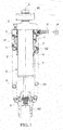
FIG. 1 is a front view partly in section showing a state where a vehicle height adjusting device according to an embodiment of the present invention and a suspension spring are assembled with a shock absorber. -
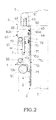
FIG. 2 is a view enlargedly showing a main part ofFIG. 1 . -
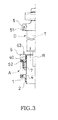
FIG. 3 is a view showing a step of assembling the vehicle height adjusting device according to the embodiment of the present invention. -
FIG. 4 is a front view partly in section showing a state where a vehicle height adjusting device of a comparative example and a suspension spring are assembled with a shock absorber. - Hereinafter, an embodiment of the present invention is described with reference to the accompanying drawings.
- As shown in
FIG. 1 , a vehicle height adjusting device according to the present embodiment is mounted on the outer periphery of an outer tube T of a shock absorber D and includes an annular movable spring bearing 1 for supporting one side end (upper end inFIG. 1 ) of a suspension spring S1 for biasing the shock absorber D in an extending direction, a driving mechanism M for driving the movable spring bearing 1 in an axial direction of the shock absorber D, an auxiliary spring S2 for biasing the movable spring bearing 1 toward the suspension spring S1 (lower side inFIG. 1 ) and a snap ring (stopper member) 2 on a wheel side for restricting a movement of the movable spring bearing 1 toward the suspension spring (lower side inFIG. 1 ). - The shock absorber D includes the outer tube T coupled to a vehicle body side via a vehicle body side bracket B1 and a piston rod R coupled to a wheel side via a wheel side bracket B2 and is set to be of an inverted type. The piston rod R is inserted into the outer tube T movably in the axial direction, and the shock absorber D extends and contracts by projecting and retracting movements of the piston rod R into and from the outer tube T.
- The shock absorber D can suppress extending and contracting motions of the suspension spring S1 by generating a predetermined damping force as it extends and contracts. Various proposals have been made on a configuration of the shock absorber D for generating a damping force and any configuration may be adopted. Thus, the detailed configuration of the shock absorber D is not described here. Further, although the shock absorber D is set to be of the inverted type in the present embodiment, it may be set to be of an upright type by coupling the piston rod R to the vehicle body side and coupling the outer tube T to the wheel side.
- The suspension spring S1 is mounted on the outer periphery of the shock absorber D. In the present embodiment, the suspension spring S1 is a coil spring. The suspension spring S1 is interposed between the movable spring bearing 1 coupled to the vehicle body side and a fixed spring bearing 3 coupled to the wheel side and biases the movable spring bearing 1 and the fixed spring bearing 3 in directions to separate them from each other. Thus, the suspension spring S1 can bias the shock absorber D in such an extending direction where the piston rod R comes out from the outer tube T.
- As described above, the movable spring bearing 1 coupled to the vehicle body side is annularly formed, mounted on the outer periphery of the outer tube T of the shock absorber D movably in the axial direction and constitutes the vehicle height adjusting device for adjusting a vehicle height by extending and contracting the shock absorber D. Further, the fixed spring bearing 3 is annularly formed, supported by the wheel side bracket B2 and pressed against the wheel side bracket B2 by the suspension spring S1 so as not to move in the axial direction.
- In the present embodiment, the vehicle height adjusting device includes the movable spring bearing 1, the driving mechanism M for driving the movable spring bearing 1 in the axial direction of the shock absorber D, the auxiliary spring S2 for biasing the movable spring bearing 1 toward the suspension spring S1, the snap ring (stopper member) 2 on the wheel side mounted on the outer periphery of the outer tube T and configured to restrict a movement of the movable spring bearing 1 toward the suspension spring S1 (lower side in
FIG. 1 ) as described above. In addition, the vehicle height adjusting device includes aguide tube 4 formed into a tubular shape and held on the outer periphery of the outer tube T and a supportingmember 5 fixed to the outer tube T of the shock absorber D and bulging outwardly from the outer tube T. - The movable spring bearing 1 is made movable in the axial direction of the shock absorber D by sliding in contact with the outer peripheral surface of the
guide tube 4, and mounted on the outer tube T of the shock absorber D via theguide tube 4. Further, as shown inFIG. 2 , the movable spring bearing 1 includes an annular bearingportion 10 for supporting a vehicle body side end (one side end) of the suspension spring S1 and atubular guide portion 11 erected substantially perpendicularly from the inner peripheral edge of a surface of thebearing portion 10 on the side of the suspension spring S1 (lower surface inFIG. 2 ), and supports the inner periphery of a vehicle body side end portion (one side end portion) of the suspension spring S1 by theguide portion 11. Further, thebearing portion 10 is so formed that an innerperipheral portion 10a is thicker than an outerperipheral portion 10b and projects toward a side opposite to the suspension spring S1 (upper side inFIG. 2 ). - The driving mechanism M for driving the movable spring bearing 1 includes a
housing 6 fixed to a side opposite to the suspension spring S1 of the movable spring bearing 1 (upper side inFIGS. 1 and2 ) on the outer periphery of theguide tube 4, a jack chamber J formed between thehousing 6 and theguide tube 4 and filled with working fluid and ajack piston 7 held in contact with a side of the movable spring bearing 1 opposite to the suspension spring 1 (upper side inFIGS. 1 and2 ) and configured to close an opening of the jack chamber J on the side of the suspension spring S1 (lower side inFIGS. 1 and2 ) by being movably inserted between thehousing 6 and theguide tube 4. Further, a pump P (FIG. 1 ) for sucking and discharging the working fluid into and from the jack chamber is connected to the driving mechanism M. - As shown in
FIG. 2 , thehousing 6 is formed into a bottomed tubular shape, includes anannular bottom portion 60 and a tubular portion 61 having a tubular shape and erected substantially perpendicularly from a surface of thebottom portion 60 on the side of the suspension spring S1 (lower surface inFIG. 2 ) and is so arranged that thebottom portion 60 is facing toward the supporting member 5 (upper side inFIG. 2 ) and the tubular portion 61 is facing toward the suspension spring S1 (lower side inFIG. 2 ). Further, thehousing 6 is fixed by being pressed against the supportingmember 5 by the suspension spring S1 and apin 63 erected from ajoint surface 62 of thehousing 6 with which the supportingmember 5 is in contact is mounted on thehousing 6. - The tubular portion 61 of the
housing 6 is arranged with a predetermined clearance defined between the tubular portion 61 and the outer periphery of theguide tube 4, and working fluid made of non-compressive liquid is stored in this clearance, thereby forming the annular jack chamber J. - The
bottom portion 60 of thehousing 6 is such that an innerperipheral portion 60a projects inwardly from the tubular portion 61 and anannular seal 64 is mounted on the inner periphery. Since theseal 64 is held in close contact with the outer peripheral surface of theguide tube 4, the outflow of the working fluid in the jack chamber J from the clearance between thebottom portion 60 of thehousing 6 and theguide tube 4 can be prevented by closing the opening of the jack chamber J opposite to the suspension spring S1 (upper side inFIG. 2 ) in a liquid-tight manner by the innerperipheral portion 60a of thebottom portion 60. - Further, the
bottom portion 60 of thehousing 6 is formed to have a larger inner diameter on the side of the supporting member 5 (upper side inFIG. 2 ) than on the other part and astep 65 is formed on the inner peripheral surface of thebottom portion 60. Furthermore, thebottom portion 60 is such that an outerperipheral portion 60b bulges outwardly from the tubular portion 61. - The
jack piston 7 includes anannular piston portion 70 for closing the opening of the jack chamber J on the side of the suspension spring S1 (lower side inFIG. 2 ) by being movably inserted between the tubular portion 61 of thehousing 6 and theguide tube 4 and an extendingportion 71 connected to a part of thepiston portion 70 on the side of the suspension spring S1 (lower side inFIG. 2 ). -
Annular seals piston portion 70, theseal 72 on an inner peripheral side slides in contact with the outer peripheral surface of theguide tube 4 and theseal 73 on an outer peripheral side slides in contact with the inner peripheral surface of the tubular portion 61. Thus, thejack piston 7 can close the opening of the jack chamber J on the side of the suspension spring S1 (lower side inFIG. 2 ) in a liquid-tight manner by sliding in contact with the outer peripheral surface of theguide tube 4 via theseal 72 on the inner peripheral side and sliding in contact with the inner peripheral surface of the tubular portion 61 via theseal 73 on the outer peripheral side. - Further, assuming that a state where the
jack piston 7 is most inserted in thehousing 6 is a jack minimum position and a state where thejack piston 7 is most retracted from thehousing 6 is a jack maximum position in a movable range of thejack piston 7, anend portion 71a of the extendingportion 71 on the side of the suspension spring S1 projects downwardly from the tubular portion 61 of thehousing 6 also at the jack minimum position where the movable spring bearing 1 is most retracted. That is, thejack piston 7 is so set that theend portion 71a of the extendingportion 71 on the side of the suspension spring S1 constantly projects from thehousing 6. - As shown in
FIG. 1 , the pump P is connected to the jack chamber J via a hose H and sucks and discharges the working fluid into and from the jack chamber J by being driven by an unillustrated motor. It should be noted that various proposals have been made on the pump P for sucking and discharging the working fluid and any configuration may be adopted. Thus, the detailed configuration of the pump P is not described here. Further, although the pump P is an electric pump to be driven by the motor in the present embodiment, it may be a manual pump to be manually driven. - The auxiliary spring S2 is a coil spring in the present embodiment. As shown in
FIG. 2 , the auxiliary spring S2 is arranged on the outer periphery of the tubular portion 61 of thehousing 6 and interposed between the outerperipheral portion 10b of thebearing portion 10 of the movable spring bearing 1 and the outerperipheral portion 60b of thebottom portion 60 of thehousing 6. Thus, the auxiliary spring S2 is arranged in series with the suspension spring S1 and acts in a direction to bias the movable spring bearing 1 toward the suspension spring S1 (lower side inFIG. 2 ) and compress the suspension spring S1. - Assuming that forces acting on the suspension spring S1 and the auxiliary spring S2 are loads, a load of the auxiliary spring S2 is maximized at the jack minimum position where the movable spring bearing 1 is most retracted in a state where the vehicle height adjusting device and the suspension spring S1 are assembled with the shock absorber D. The load of the auxiliary spring S2 at this time is referred to as an assembling-time maximum load of the auxiliary spring S2 below. Further, a load of the suspension spring S1 is minimized at the jack minimum position and when the shock absorber D is most extended in the state where the vehicle height adjusting device and the suspension spring S1 are assembled with the shock absorber D. The load of the suspension spring S1 at this time is referred to as an assembling-time minimum load of the suspension spring below.
- Since the assembling-time maximum load of the auxiliary spring S2 is set to be smaller than the assembling-time minimum load of the
suspension spring S 1, the load of the auxiliary spring S2 is constantly smaller than that of the suspension spring S1 in the state where the vehicle height adjusting device and the suspension spring S1 are assembled with the shock absorber D. Thus, themovable spring bearing 1 is constantly maintained in a state pressed against and held in contact with theend portion 71a of thejack piston 7 on the side of the suspension spring S1 by the suspension spring S1 in the state where the vehicle the suspension spring S1 and the auxiliary spring S2 are assembled. - The
guide tube 4 is formed into a tubular shape, has the outer tube T of the shock absorber D inserted thereinto and is arranged on the wheel side (lower side inFIGS. 1 and2 ) of the supportingmember 5 as described above. Further, as shown inFIG. 2 , an annular groove (not denoted by a reference sign) extending in a circumference direction is formed on each of the outer peripheries of opposite end portions of theguide tube 4, andsnap rings - The
snap ring 40 on the vehicle body side (upper side inFIG. 2 ) is set to be caught by thestep 65 formed on the inner peripheral surface of thebottom portion 60 of thehousing 6, and theguide tube 4 is held in a state suspended from thehousing 6 via thesnap ring 40. - Further, the
movable spring bearing 1 and thejack piston 7 slide in contact with theguide tube 4 between the snap rings 2, 40. In the present embodiment, thesnap ring 2 on the wheel side is a stopper member mounted on the outer periphery of the outer tube T via theguide tube 4 and configured to restrict a movement of themovable spring bearing 1 toward the suspension spring S1 (lower side inFIG. 2 ). - The
snap ring 2 on the wheel side, which is a stopper member, is provided at such a position as not to come into contact with themovable spring bearing 1 even at the jack maximum position where themovable spring bearing 1 is most advanced in a state where both the suspension spring S1 and the auxiliary spring S2 are assembled, and set not to hinder a movement of themovable spring bearing 1. - As described above, the supporting
member 5 is fixed to the outer tube T of the shock absorber D and bulges outwardly from the outer tube T. The supportingmember 5 is arranged on an end portion of the outer tube T on the vehicle body side (upper end portion inFIGS. 1 and2 ). It should be noted that the supportingmember 5 has only to be fixed to the outer tube T so as not to move and the supportingmember 5 and the outer tube T may be joined by any method such as screwing, welding, fitting or integral forming. Further, as shown inFIG. 2 , the supportingmember 5 is formed with apin insertion hole 51 perforated on ajoint surface 50 with which thehousing 6 is in contact. By inserting thepin 63 erected on thehousing 6 into thepin insertion hole 51, the rotation of thehousing 6 and the supportingmember 5 can be stopped. In the present embodiment, a rotation stopping mechanism is constituted by thepin 63 and thepin insertion hole 51. - Next, an assembling method for the vehicle height adjusting device according to the present embodiment is described.
- First, as shown in
FIG. 3 , themovable spring bearing 1, the auxiliary spring S2, the snap rings 2, 40, thehousing 6 and thejack piston 7 are mounted on the outer periphery of theguide tube 4, thereby constituting a jack assembly A. At this time, themovable spring bearing 1 is retained by the snap ring (stopper member) 2 on the wheel side and thehousing 6 is also retained by thesnap ring 40 on the vehicle body side. Thus, even if themovable spring bearing 1 and thehousing 6 are biased in directions to separate from each other by the auxiliary spring S2, themovable spring bearing 1 and thehousing 6 do not come off from theguide tube 4 and a structure as the jack assembly A can be maintained. - Then, the outer tube T of the shock absorber D having the supporting
member 5 fixed thereto is inserted into theguide tube 4 with an end opposite to the supporting member 5 (lower end inFIG. 3 ) in the lead and thepin 63 is inserted into thepin insertion hole 51. - Subsequently, the suspension spring S1 is interposed between the fixed spring bearing 3 (
FIG. 1 ) mounted on the wheel side bracket B2 fixed to the piston rod R and themovable spring bearing 1 of the jack assembly A. At this time, the jack assembly A is pressed against the supportingmember 5 by a spring force of the suspension spring S1 and fixed to the outer tube T of the shock absorber D. - Next, the operation of the vehicle height adjusting device according to the present embodiment is described.
- When the pump P is driven to supply the working fluid to the jack chamber J, the
jack piston 7 is pushed out from thehousing 6. In this way, the outer tube T is pushed upwardly inFIG. 1 and the shock absorber D is extended, wherefore the vehicle height can be increased. A state of the vehicle height adjusting device at the jack maximum position where themovable spring bearing 1 is most advanced is shown to the right of a center axis X ofFIG. 1 . - When the pump P is driven to discharge the working fluid from the jack chamber J, the
jack piston 7 is pushed into thehousing 6. In this way, the outer tube T is pushed downwardly inFIG. 1 and the shock absorber D is compressed, wherefore the vehicle height can be decreased. A state of the vehicle height adjusting device at the jack minimum position where themovable spring bearing 1 is most retracted is shown to the left of the center axis X ofFIG. 1 . - Next, functions and effects of the vehicle height adjusting device of the present embodiment are described with reference to a comparative example of the present embodiment.
-
FIG. 4 is a front view partly in section showing a state where a vehicle height adjusting device of the comparative example and a suspension spring are assembled with a shock absorber. - As shown in
FIG. 4 , the vehicle height adjusting device of the comparative example is mounted on the outer periphery of an outer tube T2 of a shock absorber D2 and includes amovable spring bearing 8 for supporting one side end (upper end inFIG. 4 ) of a suspension spring S3 for biasing the shock absorber D2 in an extending direction and a driving mechanism M2 for driving themovable spring bearing 8 in an axial direction of the shock absorber D2. - The driving mechanism M2 of the comparative example includes an
annular housing 90 fixed to a side opposite to the suspension spring S3 of the movable spring bearing 8 (upper side inFIG. 4 ) on the outer periphery of the outer tube T2, a jack chamber J2 formed between thehousing 90 and the outer tube T2 and filled with working fluid and ajack piston 91 connected to a side of themovable spring bearing 8 opposite to the suspension spring S3 (upper side inFIG. 4 ) and configured to close an opening of the jack chamber J2 on the side of the suspension spring S3 (lower side inFIG. 4 ) by being movably inserted between thehousing 90 and the outer tube T2. Further, a pump P for sucking and discharging the working fluid into and from the jack chamber J2 is connected to the driving mechanism M2. - Thus, if the vehicle height becomes too low, the
jack piston 91 is pushed out from thehousing 90 and the shock absorber D2 is extended by supplying the working fluid into the jack chamber J2 by the pump P, whereby the vehicle height can be increased. Further, if the vehicle height becomes too high, thejack piston 91 is pushed into thehousing 90 and the shock absorber D2 is compressed by discharging the working fluid from the jack chamber J2 by the pump P, whereby the vehicle height can be decreased. - However, in the case of an adjustment in a direction to increase the vehicle height by the vehicle height adjusting device of the comparative example, a large force is necessary to drive the pump P, supply the working fluid into the jack chamber J2 and push out the
jack piston 91 since a load of the suspension spring S3 is large. - Accordingly, it is considered to sandwich the
movable spring bearing 8 by the suspension spring S3 and an auxiliary spring and bias themovable spring bearing 8 toward the suspension spring S3, i.e. in a direction to compress the suspension spring S3 by the auxiliary spring in order to facilitate the supply of the working fluid into the jack chamber J2 also when the load of the suspension spring S3 is large. However, in this case, themovable spring bearing 8 moves in the axial direction and needs to be sandwiched by the suspension spring S3 and the auxiliary spring, wherefore it becomes difficult to assemble the suspension spring S3 and the auxiliary spring. - Contrary to this, the vehicle height adjusting device according to the present embodiment includes the annular
movable spring bearing 1 mounted on the outer periphery of the outer tube T of the shock absorber D and configured to support one side end (upper end inFIG. 1 ) of the suspension spring S1 for biasing the shock absorber D in the extending direction, the driving mechanism M for driving themovable spring bearing 1 in the axial direction of the shock absorber D, the auxiliary spring S2 for biasing themovable spring bearing 1 toward the suspension spring S1 (lower side inFIG. 1 ) and the snap ring (stopper member) 2 on the wheel side mounted on the outer periphery of the outer tube T and configured to restrict a movement of themovable spring bearing 1 toward the suspension spring S1 (lower side inFIG. 1 ). - According to this, even if the
movable spring bearing 1 is biased toward the suspension spring S1 (lower side inFIG. 1 ) by the auxiliary spring S2 when the suspension spring S1 is assembled, a movement of themovable spring bearing 1 can be restricted by thesnap ring 2 on the wheel side, which is a stopper member. Thus, the suspension spring S1 can be easily assembled and an assembling operation of the suspension spring S1 and the auxiliary spring S2 can be facilitated. - Further, the snap ring (stopper member) 2 can restrict a movement of the
movable spring bearing 1 toward the suspension spring S1 and also restrict a movement of thejack piston 7 toward the suspension spring S1. - Accordingly, by setting the
jack piston 7 so as not to come out of thehousing 6 in a state where themovable spring bearing 1 is in contact with the snap ring (stopper member) 2 and thejack piston 7 is in contact with themovable spring bearing 1, it can be prevented that thejack piston 7 comes out of thehousing 6 and the working fluid leaks out from the jack chamber J even if the working fluid is excessively supplied to the jack chamber J and thejack piston 7 is retracted from thehousing 6 beyond the jack maximum position. - Further, by providing the auxiliary spring S2, the working fluid can be easily supplied to the jack chamber J also when the load of the suspension spring S1 is large.
- Furthermore, in the present embodiment, the
snap ring 2 on the wheel side, which is a stopper member, is provided at such a position as not to come into contact with themovable spring bearing 1 in the state where the suspension spring S1 and the auxiliary spring S2 are assembled. - Accordingly, the snap ring (stopper member) 2 on the wheel side does not hinder a movement of the
movable spring bearing 1 in an assembling completed state where both the auxiliary spring S2 and the suspension spring S1 are assembled. Further, the snap ring (stopper member) 2 on the wheel side can restrict a movement of themovable spring bearing 1 toward the suspension spring S1 (lower side inFIG. 1 ) in a state where the suspension spring S1 is not assembled. - Further, in the present embodiment, the vehicle height adjusting device includes the
guide tube 4 held on the outer periphery of the outer tube T, and themovable spring bearing 1 and the snap ring (stopper member) 2 on the wheel side are mounted on the above outer tube T via theguide tube 4. - Accordingly, it is sufficient to apply surface processing to smoothen the outer peripheral surface of the
guide tube 4 as a slide-contact surface since themovable spring bearing 1 slides in contact with the outer peripheral surface of theguide tube 4. Surface processing can be easily performed as compared with the case where the outer peripheral surface of the outer tube T is surface-processed as a slide-contact surface. - Further, the
movable spring bearing 1 and thesnap ring 2 on the wheel side can be held on the outer periphery of theguide tube 4 when themovable spring bearing 1 and the snap ring (stopper member) 2 on the wheel side are assembled with the outer tube T of the shock absorber D after being assembled in advance to constitute the jack assembly A as in the present embodiment. Thus, themovable spring bearing 1 and thesnap ring 2 on the wheel side can be easily integrated as the jack assembly A. This is particularly effective in the case of assembling the constituted jack assembly A with the outer tube T of the shock absorber D. - Furthermore, by mounting the snap ring (stopper member) 2 on the wheel side on the
guide tube 4, themovable spring bearing 1 can be easily maintained in a range where the slide-contact surface of theguide tube 4 is formed. Thus, it can be suppressed that themovable spring bearing 1 is detached from theguide tube 4 and the inner peripheral surface of theguide tube 4 is damaged. - Further, in the present embodiment, the driving mechanism M includes the
housing 6 fixed to the side opposite to the suspension spring S1 of the movable spring bearing 1 (upper side inFIG. 1 ) on the outer periphery of theguide tube 4, the jack chamber J formed between thehousing 6 and theguide tube 4 and filled with the working fluid, and thejack piston 7 held in contact with the side of themovable spring bearing 1 opposite to the suspension spring S1 (upper side inFIG. 1 ) and configured to close the opening of the jack chamber J on the side of the suspension spring S1 (lower side inFIG. 1 ) by being movably inserted between thehousing 6 and theguide tube 4. Furthermore, the vehicle height adjusting device includes the pump P for sucking and discharging the working fluid into and from the jack chamber J. - Accordingly, the
movable spring bearing 1 can be easily driven via thejack piston 7 by sucking and discharging the working fluid into and from the jack chamber J and causing thejack piston 7 to project from and retract into thehousing 6. - Further, if the
jack piston 7 is in contact with themovable spring bearing 1 and not connected to themovable spring bearing 1 by fitting, adhesion or the like as in the present embodiment, themovable spring bearing 1 easily moves. Thus, it is particularly effective to restrict a movement of themovable spring bearing 1 by mounting the snap ring (stopper member) 2 on the wheel side. - Further, in the present embodiment, the vehicle height adjusting device includes the supporting
member 5 fixed to the outer tube T and bulging outwardly from the outer tube T. Thehousing 6 is fixed to the outer tube T via the supportingmember 5 by being pressed against the supportingmember 5 by the suspension spring S1 and theguide tube 4 is mounted on the outer tube T via thehousing 6 by being held in the state suspended from the inner periphery of thehousing 6. - Accordingly, the
housing 6 and theguide tube 4 can be fixed to the outer tube T of the shock absorber D by the spring force of the suspension spring S1 and can be easily assembled. - Further, in the present embodiment, the rotation of the
housing 6 and the supportingmember 5 are stopped by the rotation stopping mechanism (pin 63 and pin insertion hole 51). - Accordingly, even if the suspension spring S1 acts to rotate the
housing 6 relative to the supportingmember 5 as it extends and contracts when thehousing 6 is fixed by being pressed against the supportingmember 5 by the spring force of the suspension spring S1, i.e. when thehousing 6 and the supportingmember 5 are connected only by contact, such rotation can be hindered and the action of a load on the hose H linking the jack chamber J and the pump P can be suppressed. - Further, in the present embodiment, the
housing 6 is formed into a bottomed tubular shape and includes theannular bottom portion 60 to be mounted on the outer periphery of theguide tube 4 in a liquid-tight manner and the tubular portion 61 erected substantially perpendicularly from the surface of thebottom portion 60 on the side of the suspension spring S1 (lower surface inFIG. 2 ) and having the jack chamber J formed between the tubular portion 61 and theguide tube 4, the outerperipheral portion 60b of thebottom portion 60 bulges outwardly from the tubular portion 61, and the auxiliary spring S2 is interposed between the outerperipheral portion 60b of thebottom portion 60 and themovable spring bearing 1 on the outer periphery of the tubular portion 61. - Accordingly, the assembling operation of the auxiliary spring S2 can be facilitated. Further since the auxiliary spring S2 is arranged on the outer periphery of the jack chamber J, the vehicle height adjusting device can be formed compactly.
- Further, since being supported by the
housing 6, the auxiliary spring S2 can be integrated with themovable spring bearing 1, the snap ring (stopper member) 2 on the wheel side, theguide tube 4, thehousing 6 and thejack piston 7 and constitute the jack assembly A. This is particularly effective in the case of assembling the constituted jack assembly A with the outer tube T of the shock absorber D as in the present embodiment. - Further, in the present embodiment, after the jack assembly A is constituted by mounting the
movable spring bearing 1, the auxiliary spring S2, the snap ring (stopper member) 2 on the wheel side, thehousing 6 and thejack piston 7 on the outer periphery of theguide tube 4, the outer tube T is inserted into theguide tube 4, the one side end (upper end inFIG. 1 ) of the suspension spring S1 is supported on themovable spring bearing 1, and the jack assembly A is fixed to the outer tube T by being pressed against the supportingmember 5 by the suspension spring S1. - Accordingly, the assembling operation can be facilitated as compared with the case where the
movable spring bearing 1, the auxiliary spring S2, the snap ring (stopper member) 2 on the wheel side, thehousing 6 and thejack piston 7 are respectively assembled after theguide tube 4 is assembled with the outer tube T of the shock absorber D. - Embodiments of the present invention were described above, but the above embodiments are merely examples of applications of the present invention, and the technical scope of the present invention is not limited to the specific constitutions of the above embodiments.
- For example, although the stopper member is the
snap ring 2 in the above embodiment, it may be other than a snap ring and may be, for example, a projection integrally molded on theguide tube 4 or the outer tube T. - Further, in the above embodiment, the
movable spring bearing 1, the stopper member (snap ring 2 on the wheel side), thehousing 6 and thejack piston 7 are mounted on the outer periphery of theguide tube 4 and these are mounted on the outer periphery of the outer tube T of the shock absorber D via theguide tube 4. However, they may be directly mounted on the outer tube T. - Further, the configuration of the driving mechanism M for driving the
movable spring bearing 1 and the configurations and shapes of thehousing 6 and thejack piston 7 constituting the driving mechanism M are not limited to the above ones and the configurations and shapes can be appropriately selected as long as themovable spring bearing 1 can be driven. - Further, in the above embodiment, the supporting
member 5 to be fixed to the outer tube T of the shock absorber D is provided and thehousing 6 is fixed to the outer tube T by being pressed against the supportingmember 5 by the suspension spring S1. However, the method for fixing thehousing 6 is not limited to this and thehousing 6 may be fixed to the outer tube T by any method such as fitting, screwing, welding or integral forming. - Further, although the rotation of the
housing 6 and the supportingmember 5 is stopped by inserting thepin 63 erected on thehousing 6 into thepin insertion hole 51 formed on the supportingmember 5 in the above embodiment, thepin insertion hole 51 may be formed on thehousing 6 and thepin 63 may be erected on the supportingmember 5. Furthermore, the rotation of thehousing 6 and the supportingmember 5 may be stopped by a method other than thepin 63 and thepin insertion hole 51 and the configuration of the rotation stopping mechanism can be appropriately selected. - Further, although the suspension spring S1 and the auxiliary spring S2 are coil springs in the above embodiment, either one or both of them may be air spring(s). Furthermore, the mounted position of the auxiliary spring S2 is not limited to the above one and the auxiliary spring S2 may be arranged in the jack chamber J.
- Further, although the
movable spring bearing 1, the auxiliary spring S2, the stopper member (snap ring 2 on the wheel side), thehousing 6 and thejack piston 7 are assembled with the outer tube T of the shock absorber D after being mounted on the outer periphery of theguide tube 4 in advance and integrated as the jack assembly A in the above embodiment, there is no limitation to this and the assembling method can be appropriately selected. - With respect to the above description, the contents of application No.
2012-254440, with a filing date of November 20, 2012
Claims (8)
- A vehicle height adjusting device, comprising:an annular movable spring bearing mounted on the outer periphery of an outer tube of a shock absorber, the movable spring bearing being configured to support one side end of a suspension spring for biasing the shock absorber in an extending direction;a driving mechanism configured to drive the movable spring bearing in an axial direction of the shock absorber;an auxiliary spring configured to bias the movable spring bearing toward the suspension spring; anda stopper member mounted on the outer periphery of the outer tube of the shock absorber, the stopper member being configured to restrict a movement of the movable spring bearing toward the suspension spring.
- The vehicle height adjusting device according to claim 1, wherein:the stopper member is provided at such a position as not to come into contact with the movable spring bearing in a state where the suspension spring and the auxiliary spring are assembled.
- The vehicle height adjusting device according to claim 1, further comprising:a guide tube held on the outer periphery of the outer tube of the shock absorber, wherein:the movable spring bearing and the stopper member are mounted on the outer tube of the shock absorber via the guide tube.
- The vehicle height adjusting device according to claim 3, wherein:the driving mechanism comprises:a housing fixed to a side opposite to the suspension spring of the movable spring bearing on the outer periphery of the guide tube;a jack chamber formed between the housing and the guide tube and filled with working fluid; anda jack piston held in contact with a side of the movable spring bearing opposite to the suspension spring, the jack piston being configured to close an opening of the jack chamber on the side of the suspension spring by being movably inserted between the housing and the guide tube; andthe vehicle height adjusting device further comprises a pump configured to suck and discharge the working fluid into and from the jack chamber.
- The vehicle height adjusting device according to claim 4, further comprising:a supporting member fixed to the outer tube of the shock absorber and bulging outwardly from the outer tube of the shock absorber, wherein:the housing is fixed to the outer tube of the shock absorber via the supporting member by being pressed against the supporting member by the suspension spring; andthe guide tube is mounted on the outer tube of the shock absorber via the housing by being held in a state suspended from the inner periphery of the housing.
- The vehicle height adjusting device according to claim 5, further comprising:a rotation stopping mechanism configured to stop the rotation of the housing and the supporting member.
- The vehicle height adjusting device according to claim 4, wherein:the housing comprises:an annular bottom portion formed into a bottomed tubular shape and mounted on the outer periphery of the guide tube in a liquid-tight manner; anda tubular portion erected on a surface of the bottom portion on the side of the suspension spring and forming the jack chamber between the tubular portion and the guide tube;an outer peripheral portion of the bottom portion bulges outwardly from the tubular portion; andthe auxiliary spring is interposed between the outer peripheral portion of the bottom portion and the movable spring bearing on the outer periphery of the tubular portion.
- An assembling method for a vehicle height adjusting device, the vehicle height adjusting device comprising:a guide tube held on the outer periphery of an outer tube of a shock absorber;an annular movable spring bearing mounted on the outer tube of the shock absorber via the guide tube, the movable spring bearing being configured to support one side end of a suspension spring for biasing the shock absorber in an extending direction;a driving mechanism configured to drive the movable spring bearing in an axial direction of the shock absorber;an auxiliary spring configured to bias the movable spring bearing toward the suspension spring;a stopper member mounted on the outer tube of the shock absorber via the guide tube, the stopper member being configured to restrict a movement of the movable spring bearing toward the suspension spring; anda supporting member fixed to the outer tube of the shock absorber and bulging outwardly from the outer tube of the shock absorber,the assembling method comprising:inserting the outer tube of the shock absorber into the guide tube after a jack assembly is constituted by mounting the movable spring bearing, the auxiliary spring, the stopper member and the driving mechanism on the outer periphery of the guide tube; andsupporting one side end of the suspension spring on the movable spring bearing, pressing the jack assembly against the supporting member by the suspension spring and fixing the jack assembly to the outer tube of the shock absorber.
Applications Claiming Priority (2)
| Application Number | Priority Date | Filing Date | Title |
|---|---|---|---|
| JP2012254440A JP5936125B2 (en) | 2012-11-20 | 2012-11-20 | Vehicle height adjustment device and method of assembling vehicle height adjustment device |
| PCT/JP2013/080892 WO2014080842A1 (en) | 2012-11-20 | 2013-11-15 | Vehicle height adjustment device and method for mounting vehicle height adjustment device |
Publications (3)
| Publication Number | Publication Date |
|---|---|
| EP2924315A1 true EP2924315A1 (en) | 2015-09-30 |
| EP2924315A4 EP2924315A4 (en) | 2016-07-27 |
| EP2924315B1 EP2924315B1 (en) | 2018-04-11 |
Family
ID=50776025
Family Applications (1)
| Application Number | Title | Priority Date | Filing Date |
|---|---|---|---|
| EP13857441.3A Not-in-force EP2924315B1 (en) | 2012-11-20 | 2013-11-15 | Vehicle height adjustment device and method for mounting vehicle height adjustment device |
Country Status (5)
| Country | Link |
|---|---|
| US (1) | US9352631B2 (en) |
| EP (1) | EP2924315B1 (en) |
| JP (1) | JP5936125B2 (en) |
| CN (1) | CN104797843B (en) |
| WO (1) | WO2014080842A1 (en) |
Cited By (2)
| Publication number | Priority date | Publication date | Assignee | Title |
|---|---|---|---|---|
| US10479157B2 (en) * | 2015-11-13 | 2019-11-19 | Thyssenkrupp Bilstein Gmbh | Receiving arrangement of a support spring for a suspension strut |
| EP4200143A1 (en) * | 2020-08-21 | 2023-06-28 | Multimatic, Inc. | Dual rate vehicle suspension system with adjustable ride height |
Families Citing this family (20)
| Publication number | Priority date | Publication date | Assignee | Title |
|---|---|---|---|---|
| JP5936127B2 (en) * | 2012-12-06 | 2016-06-15 | Kyb株式会社 | Vehicle height adjustment device |
| US9573435B2 (en) * | 2013-09-29 | 2017-02-21 | Elka Suspension Inc. | Dual inline hydraulic device |
| US9751374B2 (en) * | 2014-09-22 | 2017-09-05 | GM Global Technology Operations LLC | Vehicle and a height adjustment system for the vehicle |
| JP2017032014A (en) * | 2015-07-30 | 2017-02-09 | Kyb株式会社 | Shock absorber |
| JP6487802B2 (en) * | 2015-07-30 | 2019-03-20 | Kyb株式会社 | Shock absorber |
| CN105172508A (en) * | 2015-10-12 | 2015-12-23 | 力帆实业(集团)股份有限公司 | Buffering device of shock absorber |
| CA3009807C (en) * | 2016-01-08 | 2019-09-17 | Multimatic Inc. | Dual rate vehicle suspension system |
| DE102016202314B4 (en) * | 2016-02-16 | 2024-05-16 | Zf Friedrichshafen Ag | Adjustable spring carrier |
| JP6788984B2 (en) * | 2016-03-28 | 2020-11-25 | Kyb株式会社 | Buffer |
| US10052928B2 (en) * | 2016-04-07 | 2018-08-21 | GM Global Technology Operations LLC | Ride height control actuator |
| US10160279B2 (en) * | 2016-11-23 | 2018-12-25 | GM Global Technology Operations LLC | Hydraulically operated actuator for controlling vehicle ride height |
| DE102018212109A1 (en) * | 2018-07-20 | 2020-01-23 | Bayerische Motoren Werke Aktiengesellschaft | Height adjustable spring assembly for a vehicle |
| KR102635917B1 (en) * | 2018-08-29 | 2024-02-08 | 현대자동차주식회사 | Apparatus of adjusting vehicle height for suspension |
| US11021031B2 (en) * | 2018-10-29 | 2021-06-01 | Polaris Industries Inc. | Suspension pre-load adjustment system |
| US10953717B2 (en) * | 2019-05-13 | 2021-03-23 | Honda Motor Co., Ltd. | Wear mitigated damper assembly for a vehicle |
| CN110654193A (en) * | 2019-08-27 | 2020-01-07 | 重庆长安汽车股份有限公司 | A shock absorber with adjustable body height |
| US11400790B2 (en) * | 2020-01-30 | 2022-08-02 | Schaeffler Technologies AG & Co. KG | Concentric hydraulic ride height actuator for a motor vehicle |
| JP7503003B2 (en) * | 2021-01-19 | 2024-06-19 | カヤバモーターサイクルサスペンション株式会社 | Shock absorber |
| CN113103838B (en) * | 2021-05-08 | 2023-01-31 | 南京信息职业技术学院 | Suspension lifting device suitable for new energy automobile and new energy automobile |
| JP7671191B2 (en) * | 2021-07-05 | 2025-05-01 | カヤバ株式会社 | Shock absorber with height adjustment function |
Family Cites Families (21)
| Publication number | Priority date | Publication date | Assignee | Title |
|---|---|---|---|---|
| JP2514195B2 (en) * | 1986-12-23 | 1996-07-10 | 株式会社 昌和製作所 | Shock absorber with vehicle height adjuster |
| JPH0659769B2 (en) * | 1987-10-19 | 1994-08-10 | 日産自動車株式会社 | Double link type suspension system |
| ES2087603T3 (en) * | 1989-11-10 | 1996-07-16 | Suzuki Co Ltd | MOTORCYCLE WITH BODY HEIGHT ADJUSTMENT MECHANISM. |
| JP2911556B2 (en) * | 1990-07-09 | 1999-06-23 | 株式会社ショーワ | Hydraulic shock absorber for vehicles with jack unit for height adjustment |
| JPH04131531A (en) * | 1990-09-20 | 1992-05-06 | Nissan Motor Co Ltd | Spring for suspension |
| JP2585418Y2 (en) * | 1993-02-26 | 1998-11-18 | カヤバ工業株式会社 | Height adjustment device |
| JPH07332424A (en) * | 1994-06-01 | 1995-12-22 | Showa:Kk | Spring initial load adjustment mechanism for shock absorber |
| JPH0996333A (en) * | 1995-09-29 | 1997-04-08 | Kayaba Ind Co Ltd | Mounting length adjustment structure |
| JPH1044738A (en) * | 1996-08-06 | 1998-02-17 | Showa:Kk | Height adjustment device |
| JPH10299811A (en) * | 1997-04-25 | 1998-11-13 | Showa:Kk | Vehicle height adjusting device and method of using the same |
| JP2000055108A (en) * | 1998-08-03 | 2000-02-22 | Honda Motor Co Ltd | Damper with height adjustment function |
| JP4254983B2 (en) * | 1999-11-19 | 2009-04-15 | 株式会社ショーワ | Hydraulic shock absorber |
| JP2005106256A (en) * | 2003-10-02 | 2005-04-21 | Sumitomo Rubber Ind Ltd | Suspension device |
| JP2006044482A (en) * | 2004-08-05 | 2006-02-16 | Sumitomo Rubber Ind Ltd | Suspension device |
| JP4602876B2 (en) * | 2005-09-07 | 2010-12-22 | カヤバ工業株式会社 | Adjustment mechanism of initial load in suspension spring of shock absorber |
| JP4839196B2 (en) * | 2006-03-28 | 2011-12-21 | カヤバ工業株式会社 | Vehicle height adjustment device |
| JP4500786B2 (en) * | 2006-04-27 | 2010-07-14 | カヤバ工業株式会社 | Shock absorber |
| JP4998936B2 (en) * | 2006-06-19 | 2012-08-15 | ヤマハモーターハイドロリックシステム株式会社 | Spring characteristic variable device in vehicle suspension system |
| JP4726077B2 (en) * | 2006-11-24 | 2011-07-20 | カヤバ工業株式会社 | Shock absorber with height adjustment function |
| DE102007015888A1 (en) * | 2007-04-02 | 2008-10-09 | Bayerische Motoren Werke Aktiengesellschaft | Spring arrangement with adjustable spring rate and strut |
| JP5379468B2 (en) | 2008-12-24 | 2013-12-25 | カヤバ工業株式会社 | Vehicle height adjustment device |
-
2012
- 2012-11-20 JP JP2012254440A patent/JP5936125B2/en active Active
-
2013
- 2013-11-15 CN CN201380059795.7A patent/CN104797843B/en not_active Expired - Fee Related
- 2013-11-15 EP EP13857441.3A patent/EP2924315B1/en not_active Not-in-force
- 2013-11-15 WO PCT/JP2013/080892 patent/WO2014080842A1/en not_active Ceased
- 2013-11-15 US US14/439,671 patent/US9352631B2/en not_active Expired - Fee Related
Cited By (2)
| Publication number | Priority date | Publication date | Assignee | Title |
|---|---|---|---|---|
| US10479157B2 (en) * | 2015-11-13 | 2019-11-19 | Thyssenkrupp Bilstein Gmbh | Receiving arrangement of a support spring for a suspension strut |
| EP4200143A1 (en) * | 2020-08-21 | 2023-06-28 | Multimatic, Inc. | Dual rate vehicle suspension system with adjustable ride height |
Also Published As
| Publication number | Publication date |
|---|---|
| US9352631B2 (en) | 2016-05-31 |
| JP5936125B2 (en) | 2016-06-15 |
| EP2924315B1 (en) | 2018-04-11 |
| JP2014101944A (en) | 2014-06-05 |
| CN104797843B (en) | 2016-09-21 |
| CN104797843A (en) | 2015-07-22 |
| US20150290992A1 (en) | 2015-10-15 |
| WO2014080842A1 (en) | 2014-05-30 |
| EP2924315A4 (en) | 2016-07-27 |
Similar Documents
| Publication | Publication Date | Title |
|---|---|---|
| US9352631B2 (en) | Vehicle height adjusting device and assembling method for vehicle height adjusting device | |
| CN104838166B (en) | Vehicle height adjustment device | |
| US8408561B2 (en) | Vehicle height adjusting device | |
| CN101240830A (en) | hydraulic buffer | |
| CN101883932B (en) | Vibration damping device | |
| US11231109B2 (en) | Method for manufacturing sealing device, and sealing device | |
| US20190176558A1 (en) | Adjustable Spring Bracke | |
| US8047340B2 (en) | Suspension spring adjusting apparatus of hydraulic shock absorber | |
| CN106051018B (en) | The damper and vehicle chassis of adjustable bodywork height | |
| JP7671191B2 (en) | Shock absorber with height adjustment function | |
| EP3196503A1 (en) | Shock absorber | |
| JP6764865B2 (en) | Suspension damping device with hydraulic device and such device to adjust the ground clearance of the vehicle | |
| JP2014084972A (en) | Car height adjustment device | |
| CN119677973A (en) | Anti-vibration device | |
| KR101778517B1 (en) | Double-lip seal of brake chamber for vehicle | |
| CN221293455U (en) | Pedal sense simulator and automobile | |
| JP4836743B2 (en) | Seal structure of sliding part | |
| CN118896127B (en) | Air spring and vehicle | |
| CN222479313U (en) | Guide rod assembly, base assembly and air spring damper | |
| JP5110285B2 (en) | Hydraulic shock absorber | |
| CN205877052U (en) | Shock absorber and vehicle chassis of adjustable automobile body height | |
| CN120819597A (en) | An air spring | |
| CN121773278A (en) | Vehicle height adjusting device | |
| JP2016064727A (en) | Front fork |
Legal Events
| Date | Code | Title | Description |
|---|---|---|---|
| PUAI | Public reference made under article 153(3) epc to a published international application that has entered the european phase |
Free format text: ORIGINAL CODE: 0009012 |
|
| 17P | Request for examination filed |
Effective date: 20150616 |
|
| AK | Designated contracting states |
Kind code of ref document: A1 Designated state(s): AL AT BE BG CH CY CZ DE DK EE ES FI FR GB GR HR HU IE IS IT LI LT LU LV MC MK MT NL NO PL PT RO RS SE SI SK SM TR |
|
| AX | Request for extension of the european patent |
Extension state: BA ME |
|
| RAP1 | Party data changed (applicant data changed or rights of an application transferred) |
Owner name: KYB CORPORATION |
|
| DAX | Request for extension of the european patent (deleted) | ||
| RA4 | Supplementary search report drawn up and despatched (corrected) |
Effective date: 20160623 |
|
| RIC1 | Information provided on ipc code assigned before grant |
Ipc: F16F 9/32 20060101ALI20160617BHEP Ipc: B60G 17/08 20060101ALI20160617BHEP Ipc: B60G 15/06 20060101ALI20160617BHEP Ipc: F16F 9/46 20060101AFI20160617BHEP |
|
| GRAP | Despatch of communication of intention to grant a patent |
Free format text: ORIGINAL CODE: EPIDOSNIGR1 |
|
| INTG | Intention to grant announced |
Effective date: 20171121 |
|
| GRAS | Grant fee paid |
Free format text: ORIGINAL CODE: EPIDOSNIGR3 |
|
| RIN1 | Information on inventor provided before grant (corrected) |
Inventor name: AMANO, YUKI Inventor name: MOCHIZUKI, TAKAHISA |
|
| GRAA | (expected) grant |
Free format text: ORIGINAL CODE: 0009210 |
|
| AK | Designated contracting states |
Kind code of ref document: B1 Designated state(s): AL AT BE BG CH CY CZ DE DK EE ES FI FR GB GR HR HU IE IS IT LI LT LU LV MC MK MT NL NO PL PT RO RS SE SI SK SM TR |
|
| REG | Reference to a national code |
Ref country code: GB Ref legal event code: FG4D |
|
| REG | Reference to a national code |
Ref country code: CH Ref legal event code: EP |
|
| REG | Reference to a national code |
Ref country code: AT Ref legal event code: REF Ref document number: 988369 Country of ref document: AT Kind code of ref document: T Effective date: 20180415 |
|
| REG | Reference to a national code |
Ref country code: IE Ref legal event code: FG4D |
|
| REG | Reference to a national code |
Ref country code: DE Ref legal event code: R096 Ref document number: 602013035901 Country of ref document: DE |
|
| REG | Reference to a national code |
Ref country code: NL Ref legal event code: MP Effective date: 20180411 |
|
| REG | Reference to a national code |
Ref country code: LT Ref legal event code: MG4D |
|
| PG25 | Lapsed in a contracting state [announced via postgrant information from national office to epo] |
Ref country code: NL Free format text: LAPSE BECAUSE OF FAILURE TO SUBMIT A TRANSLATION OF THE DESCRIPTION OR TO PAY THE FEE WITHIN THE PRESCRIBED TIME-LIMIT Effective date: 20180411 |
|
| PG25 | Lapsed in a contracting state [announced via postgrant information from national office to epo] |
Ref country code: FI Free format text: LAPSE BECAUSE OF FAILURE TO SUBMIT A TRANSLATION OF THE DESCRIPTION OR TO PAY THE FEE WITHIN THE PRESCRIBED TIME-LIMIT Effective date: 20180411 Ref country code: LT Free format text: LAPSE BECAUSE OF FAILURE TO SUBMIT A TRANSLATION OF THE DESCRIPTION OR TO PAY THE FEE WITHIN THE PRESCRIBED TIME-LIMIT Effective date: 20180411 Ref country code: PL Free format text: LAPSE BECAUSE OF FAILURE TO SUBMIT A TRANSLATION OF THE DESCRIPTION OR TO PAY THE FEE WITHIN THE PRESCRIBED TIME-LIMIT Effective date: 20180411 Ref country code: BG Free format text: LAPSE BECAUSE OF FAILURE TO SUBMIT A TRANSLATION OF THE DESCRIPTION OR TO PAY THE FEE WITHIN THE PRESCRIBED TIME-LIMIT Effective date: 20180711 Ref country code: SE Free format text: LAPSE BECAUSE OF FAILURE TO SUBMIT A TRANSLATION OF THE DESCRIPTION OR TO PAY THE FEE WITHIN THE PRESCRIBED TIME-LIMIT Effective date: 20180411 Ref country code: NO Free format text: LAPSE BECAUSE OF FAILURE TO SUBMIT A TRANSLATION OF THE DESCRIPTION OR TO PAY THE FEE WITHIN THE PRESCRIBED TIME-LIMIT Effective date: 20180711 Ref country code: AL Free format text: LAPSE BECAUSE OF FAILURE TO SUBMIT A TRANSLATION OF THE DESCRIPTION OR TO PAY THE FEE WITHIN THE PRESCRIBED TIME-LIMIT Effective date: 20180411 Ref country code: ES Free format text: LAPSE BECAUSE OF FAILURE TO SUBMIT A TRANSLATION OF THE DESCRIPTION OR TO PAY THE FEE WITHIN THE PRESCRIBED TIME-LIMIT Effective date: 20180411 |
|
| PG25 | Lapsed in a contracting state [announced via postgrant information from national office to epo] |
Ref country code: GR Free format text: LAPSE BECAUSE OF FAILURE TO SUBMIT A TRANSLATION OF THE DESCRIPTION OR TO PAY THE FEE WITHIN THE PRESCRIBED TIME-LIMIT Effective date: 20180712 Ref country code: HR Free format text: LAPSE BECAUSE OF FAILURE TO SUBMIT A TRANSLATION OF THE DESCRIPTION OR TO PAY THE FEE WITHIN THE PRESCRIBED TIME-LIMIT Effective date: 20180411 Ref country code: RS Free format text: LAPSE BECAUSE OF FAILURE TO SUBMIT A TRANSLATION OF THE DESCRIPTION OR TO PAY THE FEE WITHIN THE PRESCRIBED TIME-LIMIT Effective date: 20180411 Ref country code: LV Free format text: LAPSE BECAUSE OF FAILURE TO SUBMIT A TRANSLATION OF THE DESCRIPTION OR TO PAY THE FEE WITHIN THE PRESCRIBED TIME-LIMIT Effective date: 20180411 |
|
| REG | Reference to a national code |
Ref country code: AT Ref legal event code: MK05 Ref document number: 988369 Country of ref document: AT Kind code of ref document: T Effective date: 20180411 |
|
| PG25 | Lapsed in a contracting state [announced via postgrant information from national office to epo] |
Ref country code: PT Free format text: LAPSE BECAUSE OF FAILURE TO SUBMIT A TRANSLATION OF THE DESCRIPTION OR TO PAY THE FEE WITHIN THE PRESCRIBED TIME-LIMIT Effective date: 20180813 |
|
| REG | Reference to a national code |
Ref country code: DE Ref legal event code: R097 Ref document number: 602013035901 Country of ref document: DE |
|
| PG25 | Lapsed in a contracting state [announced via postgrant information from national office to epo] |
Ref country code: DK Free format text: LAPSE BECAUSE OF FAILURE TO SUBMIT A TRANSLATION OF THE DESCRIPTION OR TO PAY THE FEE WITHIN THE PRESCRIBED TIME-LIMIT Effective date: 20180411 Ref country code: EE Free format text: LAPSE BECAUSE OF FAILURE TO SUBMIT A TRANSLATION OF THE DESCRIPTION OR TO PAY THE FEE WITHIN THE PRESCRIBED TIME-LIMIT Effective date: 20180411 Ref country code: AT Free format text: LAPSE BECAUSE OF FAILURE TO SUBMIT A TRANSLATION OF THE DESCRIPTION OR TO PAY THE FEE WITHIN THE PRESCRIBED TIME-LIMIT Effective date: 20180411 Ref country code: CZ Free format text: LAPSE BECAUSE OF FAILURE TO SUBMIT A TRANSLATION OF THE DESCRIPTION OR TO PAY THE FEE WITHIN THE PRESCRIBED TIME-LIMIT Effective date: 20180411 Ref country code: SK Free format text: LAPSE BECAUSE OF FAILURE TO SUBMIT A TRANSLATION OF THE DESCRIPTION OR TO PAY THE FEE WITHIN THE PRESCRIBED TIME-LIMIT Effective date: 20180411 Ref country code: RO Free format text: LAPSE BECAUSE OF FAILURE TO SUBMIT A TRANSLATION OF THE DESCRIPTION OR TO PAY THE FEE WITHIN THE PRESCRIBED TIME-LIMIT Effective date: 20180411 |
|
| PGFP | Annual fee paid to national office [announced via postgrant information from national office to epo] |
Ref country code: DE Payment date: 20181126 Year of fee payment: 6 |
|
| PLBE | No opposition filed within time limit |
Free format text: ORIGINAL CODE: 0009261 |
|
| STAA | Information on the status of an ep patent application or granted ep patent |
Free format text: STATUS: NO OPPOSITION FILED WITHIN TIME LIMIT |
|
| PG25 | Lapsed in a contracting state [announced via postgrant information from national office to epo] |
Ref country code: SM Free format text: LAPSE BECAUSE OF FAILURE TO SUBMIT A TRANSLATION OF THE DESCRIPTION OR TO PAY THE FEE WITHIN THE PRESCRIBED TIME-LIMIT Effective date: 20180411 |
|
| PGFP | Annual fee paid to national office [announced via postgrant information from national office to epo] |
Ref country code: GB Payment date: 20181123 Year of fee payment: 6 Ref country code: IT Payment date: 20181130 Year of fee payment: 6 Ref country code: FR Payment date: 20181122 Year of fee payment: 6 |
|
| 26N | No opposition filed |
Effective date: 20190114 |
|
| PG25 | Lapsed in a contracting state [announced via postgrant information from national office to epo] |
Ref country code: SI Free format text: LAPSE BECAUSE OF FAILURE TO SUBMIT A TRANSLATION OF THE DESCRIPTION OR TO PAY THE FEE WITHIN THE PRESCRIBED TIME-LIMIT Effective date: 20180411 |
|
| REG | Reference to a national code |
Ref country code: CH Ref legal event code: PL |
|
| PG25 | Lapsed in a contracting state [announced via postgrant information from national office to epo] |
Ref country code: MC Free format text: LAPSE BECAUSE OF FAILURE TO SUBMIT A TRANSLATION OF THE DESCRIPTION OR TO PAY THE FEE WITHIN THE PRESCRIBED TIME-LIMIT Effective date: 20180411 Ref country code: LU Free format text: LAPSE BECAUSE OF NON-PAYMENT OF DUE FEES Effective date: 20181115 |
|
| REG | Reference to a national code |
Ref country code: BE Ref legal event code: MM Effective date: 20181130 |
|
| REG | Reference to a national code |
Ref country code: IE Ref legal event code: MM4A |
|
| PG25 | Lapsed in a contracting state [announced via postgrant information from national office to epo] |
Ref country code: CH Free format text: LAPSE BECAUSE OF NON-PAYMENT OF DUE FEES Effective date: 20181130 Ref country code: LI Free format text: LAPSE BECAUSE OF NON-PAYMENT OF DUE FEES Effective date: 20181130 |
|
| PG25 | Lapsed in a contracting state [announced via postgrant information from national office to epo] |
Ref country code: IE Free format text: LAPSE BECAUSE OF NON-PAYMENT OF DUE FEES Effective date: 20181115 |
|
| PG25 | Lapsed in a contracting state [announced via postgrant information from national office to epo] |
Ref country code: BE Free format text: LAPSE BECAUSE OF NON-PAYMENT OF DUE FEES Effective date: 20181130 |
|
| PG25 | Lapsed in a contracting state [announced via postgrant information from national office to epo] |
Ref country code: MT Free format text: LAPSE BECAUSE OF NON-PAYMENT OF DUE FEES Effective date: 20181115 |
|
| PG25 | Lapsed in a contracting state [announced via postgrant information from national office to epo] |
Ref country code: TR Free format text: LAPSE BECAUSE OF FAILURE TO SUBMIT A TRANSLATION OF THE DESCRIPTION OR TO PAY THE FEE WITHIN THE PRESCRIBED TIME-LIMIT Effective date: 20180411 |
|
| REG | Reference to a national code |
Ref country code: DE Ref legal event code: R119 Ref document number: 602013035901 Country of ref document: DE |
|
| PG25 | Lapsed in a contracting state [announced via postgrant information from national office to epo] |
Ref country code: CY Free format text: LAPSE BECAUSE OF FAILURE TO SUBMIT A TRANSLATION OF THE DESCRIPTION OR TO PAY THE FEE WITHIN THE PRESCRIBED TIME-LIMIT Effective date: 20180411 Ref country code: HU Free format text: LAPSE BECAUSE OF FAILURE TO SUBMIT A TRANSLATION OF THE DESCRIPTION OR TO PAY THE FEE WITHIN THE PRESCRIBED TIME-LIMIT; INVALID AB INITIO Effective date: 20131115 Ref country code: MK Free format text: LAPSE BECAUSE OF NON-PAYMENT OF DUE FEES Effective date: 20180411 |
|
| PG25 | Lapsed in a contracting state [announced via postgrant information from national office to epo] |
Ref country code: IS Free format text: LAPSE BECAUSE OF FAILURE TO SUBMIT A TRANSLATION OF THE DESCRIPTION OR TO PAY THE FEE WITHIN THE PRESCRIBED TIME-LIMIT Effective date: 20180811 |
|
| GBPC | Gb: european patent ceased through non-payment of renewal fee |
Effective date: 20191115 |
|
| PG25 | Lapsed in a contracting state [announced via postgrant information from national office to epo] |
Ref country code: GB Free format text: LAPSE BECAUSE OF NON-PAYMENT OF DUE FEES Effective date: 20191115 Ref country code: IT Free format text: LAPSE BECAUSE OF NON-PAYMENT OF DUE FEES Effective date: 20191115 Ref country code: FR Free format text: LAPSE BECAUSE OF NON-PAYMENT OF DUE FEES Effective date: 20191130 Ref country code: DE Free format text: LAPSE BECAUSE OF NON-PAYMENT OF DUE FEES Effective date: 20200603 |