EP2923891A2 - Vehicle interior lighting device - Google Patents
Vehicle interior lighting device Download PDFInfo
- Publication number
- EP2923891A2 EP2923891A2 EP15152982.3A EP15152982A EP2923891A2 EP 2923891 A2 EP2923891 A2 EP 2923891A2 EP 15152982 A EP15152982 A EP 15152982A EP 2923891 A2 EP2923891 A2 EP 2923891A2
- Authority
- EP
- European Patent Office
- Prior art keywords
- light
- mode
- emitting
- emitting elements
- door
- Prior art date
- Legal status (The legal status is an assumption and is not a legal conclusion. Google has not performed a legal analysis and makes no representation as to the accuracy of the status listed.)
- Withdrawn
Links
Images






Classifications
-
- F—MECHANICAL ENGINEERING; LIGHTING; HEATING; WEAPONS; BLASTING
- F21—LIGHTING
- F21V—FUNCTIONAL FEATURES OR DETAILS OF LIGHTING DEVICES OR SYSTEMS THEREOF; STRUCTURAL COMBINATIONS OF LIGHTING DEVICES WITH OTHER ARTICLES, NOT OTHERWISE PROVIDED FOR
- F21V23/00—Arrangement of electric circuit elements in or on lighting devices
- F21V23/003—Arrangement of electric circuit elements in or on lighting devices the elements being electronics drivers or controllers for operating the light source, e.g. for a LED array
-
- H—ELECTRICITY
- H05—ELECTRIC TECHNIQUES NOT OTHERWISE PROVIDED FOR
- H05B—ELECTRIC HEATING; ELECTRIC LIGHT SOURCES NOT OTHERWISE PROVIDED FOR; CIRCUIT ARRANGEMENTS FOR ELECTRIC LIGHT SOURCES, IN GENERAL
- H05B45/00—Circuit arrangements for operating light-emitting diodes [LED]
-
- B—PERFORMING OPERATIONS; TRANSPORTING
- B60—VEHICLES IN GENERAL
- B60Q—ARRANGEMENT OF SIGNALLING OR LIGHTING DEVICES, THE MOUNTING OR SUPPORTING THEREOF OR CIRCUITS THEREFOR, FOR VEHICLES IN GENERAL
- B60Q3/00—Arrangement of lighting devices for vehicle interiors; Lighting devices specially adapted for vehicle interiors
- B60Q3/60—Arrangement of lighting devices for vehicle interiors; Lighting devices specially adapted for vehicle interiors characterised by optical aspects
- B60Q3/62—Arrangement of lighting devices for vehicle interiors; Lighting devices specially adapted for vehicle interiors characterised by optical aspects using light guides
- B60Q3/64—Arrangement of lighting devices for vehicle interiors; Lighting devices specially adapted for vehicle interiors characterised by optical aspects using light guides for a single lighting device
-
- B—PERFORMING OPERATIONS; TRANSPORTING
- B60—VEHICLES IN GENERAL
- B60Q—ARRANGEMENT OF SIGNALLING OR LIGHTING DEVICES, THE MOUNTING OR SUPPORTING THEREOF OR CIRCUITS THEREFOR, FOR VEHICLES IN GENERAL
- B60Q3/00—Arrangement of lighting devices for vehicle interiors; Lighting devices specially adapted for vehicle interiors
- B60Q3/70—Arrangement of lighting devices for vehicle interiors; Lighting devices specially adapted for vehicle interiors characterised by the purpose
- B60Q3/74—Arrangement of lighting devices for vehicle interiors; Lighting devices specially adapted for vehicle interiors characterised by the purpose for overall compartment lighting; for overall compartment lighting in combination with specific lighting, e.g. room lamps with reading lamps
-
- B—PERFORMING OPERATIONS; TRANSPORTING
- B60—VEHICLES IN GENERAL
- B60Q—ARRANGEMENT OF SIGNALLING OR LIGHTING DEVICES, THE MOUNTING OR SUPPORTING THEREOF OR CIRCUITS THEREFOR, FOR VEHICLES IN GENERAL
- B60Q3/00—Arrangement of lighting devices for vehicle interiors; Lighting devices specially adapted for vehicle interiors
- B60Q3/80—Circuits; Control arrangements
-
- B—PERFORMING OPERATIONS; TRANSPORTING
- B60—VEHICLES IN GENERAL
- B60Q—ARRANGEMENT OF SIGNALLING OR LIGHTING DEVICES, THE MOUNTING OR SUPPORTING THEREOF OR CIRCUITS THEREFOR, FOR VEHICLES IN GENERAL
- B60Q3/00—Arrangement of lighting devices for vehicle interiors; Lighting devices specially adapted for vehicle interiors
- B60Q3/80—Circuits; Control arrangements
- B60Q3/82—Switches specially adapted for vehicle interior lighting, e.g. switching by tilting the lens
-
- F—MECHANICAL ENGINEERING; LIGHTING; HEATING; WEAPONS; BLASTING
- F21—LIGHTING
- F21S—NON-PORTABLE LIGHTING DEVICES; SYSTEMS THEREOF; VEHICLE LIGHTING DEVICES SPECIALLY ADAPTED FOR VEHICLE EXTERIORS
- F21S43/00—Signalling devices specially adapted for vehicle exteriors, e.g. brake lamps, direction indicator lights or reversing lights
-
- F—MECHANICAL ENGINEERING; LIGHTING; HEATING; WEAPONS; BLASTING
- F21—LIGHTING
- F21V—FUNCTIONAL FEATURES OR DETAILS OF LIGHTING DEVICES OR SYSTEMS THEREOF; STRUCTURAL COMBINATIONS OF LIGHTING DEVICES WITH OTHER ARTICLES, NOT OTHERWISE PROVIDED FOR
- F21V23/00—Arrangement of electric circuit elements in or on lighting devices
- F21V23/04—Arrangement of electric circuit elements in or on lighting devices the elements being switches
-
- F—MECHANICAL ENGINEERING; LIGHTING; HEATING; WEAPONS; BLASTING
- F21—LIGHTING
- F21W—INDEXING SCHEME ASSOCIATED WITH SUBCLASSES F21K, F21L, F21S and F21V, RELATING TO USES OR APPLICATIONS OF LIGHTING DEVICES OR SYSTEMS
- F21W2106/00—Interior vehicle lighting devices
-
- F—MECHANICAL ENGINEERING; LIGHTING; HEATING; WEAPONS; BLASTING
- F21—LIGHTING
- F21W—INDEXING SCHEME ASSOCIATED WITH SUBCLASSES F21K, F21L, F21S and F21V, RELATING TO USES OR APPLICATIONS OF LIGHTING DEVICES OR SYSTEMS
- F21W2107/00—Use or application of lighting devices on or in particular types of vehicles
- F21W2107/10—Use or application of lighting devices on or in particular types of vehicles for land vehicles
-
- H—ELECTRICITY
- H05—ELECTRIC TECHNIQUES NOT OTHERWISE PROVIDED FOR
- H05B—ELECTRIC HEATING; ELECTRIC LIGHT SOURCES NOT OTHERWISE PROVIDED FOR; CIRCUIT ARRANGEMENTS FOR ELECTRIC LIGHT SOURCES, IN GENERAL
- H05B45/00—Circuit arrangements for operating light-emitting diodes [LED]
- H05B45/10—Controlling the intensity of the light
Definitions
- Embodiments described herein relate to a vehicle interior lighting device.
- a vehicle interior lighting device including a light-emitting diode as a light source and provided in the interior of an automobile.
- Such a vehicle interior lighting device includes a switch for switching an ON mode for lighting the light-emitting diode, an OFF mode for extinguishing the light-emitting diode, and a DOOR mode for lighting the light-emitting diode when a door of the vehicle is in an open state and extinguishing the light-emitting diode when doors of the vehicle are in a closed state.
- the vehicle interior lighting device distinguishes the modes according to states of an operation section of the switch.
- a vehicle interior lighting device including: a plurality of light-emitting elements; a switch for switching an ON mode for lighting at least a part of the plurality of light-emitting elements and a DOOR mode for lighting at least a part of the plurality of light-emitting elements when a door of a vehicle is in an open state and extinguishing the plurality of light-emitting elements when doors of the vehicle are in a closed state; and a control section configured to control light-emitting states of the plurality of light-emitting elements to set an amount of light in the DOOR mode to be more than an amount of light in the ON mode.
- the vehicle interior lighting device it is possible to easily distinguish the ON mode and the DOOR mode and improve the safety in getting on and off the vehicle.
- the control section can control the light-emitting states of the plurality of light-emitting elements to further set a lighting pattern in the ON mode and a lighting pattern in the DOOR mode to be different from each other.
- the control section can control the light-emitting states of the plurality of light-emitting elements to further set a light-emitting region in the ON mode and a light-emitting region in the DOOR mode to be different from each other.
- the transmittance of light of a first member provided in the light-emitting region in the ON mode can be set different from the transmittance of light of a second member provided in the light-emitting region in the DOOR mode.
- the first member and the second member can be joined by a two-color molding method or fitting.
- An end section on a light incident side of the second member can be formed to face a part of the plurality of light-emitting elements.
- a vehicle interior lighting device including: a plurality of first light-emitting elements; a plurality of second light-emitting elements; a switch for switching an ON mode for lighting at least a part of the plurality of first light-emitting elements and the plurality of second light-emitting elements and a DOOR mode for lighting at least a part of the plurality of first light-emitting elements and the plurality of second light-emitting elements when a door of a vehicle is in an open state and extinguishing the plurality of first light-emitting elements and the plurality of second light-emitting elements when doors of the vehicle are in a closed state; and a control section configured to control light-emitting states of the plurality of first light-emitting elements and the plurality of second light-emitting elements to set at least any one of a light-emitting color, chromaticity, and color temperature in the ON mode and at least any one of a light-emitting color, chromat
- the control section can control light-emitting states of the plurality of first light-emitting elements and the plurality of second light-emitting elements to further set a lighting pattern in the ON mode and a lighting pattern in the DOOR mode to be different from each other.
- the control section can control light-emitting states of the plurality of first light-emitting elements and the plurality of second light-emitting elements to further set a light-emitting region in the ON mode and a light-emitting region in the DOOR mode to be different from each other.
- the transmittance of light of a first member provided in the light-emitting region in the ON mode can be set different from the transmittance of light of a second member provided in the light-emitting region in the DOOR mode.
- the first member and the second member can be joined by a two-color molding method or fitting.
- An end section on a light incident side of the second member can be formed to face a part of the plurality of first light-emitting elements and the plurality of second light-emitting elements.
- a vehicle interior lighting device including: a plurality of light-emitting elements; a switch for switching an ON mode for lighting at least a part of the plurality of light-emitting elements and a DOOR mode for lighting at least a part of the plurality of light-emitting elements when a door of a vehicle is in an open state and extinguishing the plurality of light-emitting elements when doors of the vehicle are in a closed state; and a control section configured to control light-emitting states of the plurality of light-emitting elements to set a light-emitting region in the ON mode and a light-emitting region in the DOOR mode to be different from each other.
- the vehicle interior lighting device can further include an optical element provided in at least one of the light-emitting region in the ON mode and the light-emitting region in the DOOR mode and configured to generate a desired light condensation characteristic and a desired luminous intensity distribution characteristic.
- the control section can control light-emitting states of the plurality of light-emitting elements to cause the plurality of light-emitting elements to irradiate light on an entire vehicle interior in the ON mode and irradiate light on at least one of the vicinities of the doors of the vehicle and the vicinities of seats in the DOOR mode.
- the transmittance of light of a first member provided in the light-emitting region in the ON mode can be set different from the transmittance of light of a second member provided in the light-emitting region in the DOOR mode.
- the first member and the second member can be joined by a two-color molding method or fitting.
- An end section on a light incident side of the second member can be formed to face a part of the plurality of light-emitting elements.
- the control section can control light-emitting states of the plurality of light-emitting elements to further set at least any one of a light-emitting color, chromaticity, color temperature, and an amount of light in the ON mode and at least any one of a light-emitting color, chromaticity, color temperature, and an amount of light in the DOOR mode to be different from each other.
- the control section can control light-emitting states of the plurality of light-emitting elements to further set a lighting pattern in the ON mode and a lighting pattern in the DOOR mode to be different from each other.
- FIG. 1 is a schematic perspective view for illustrating a vehicle interior lighting device 1 according to an embodiment.
- FIG. 2 is a schematic sectional view of the vehicle interior lighting device 1.
- FIG. 2 is a schematic sectional view in an A-A line direction in FIG. 1 .
- FIG. 3 is a schematic exploded view of the vehicle interior lighting device 1.
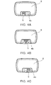
- FIGS. 4A to 4C are schematic views for illustrating switching of modes.
- the vehicle interior lighting device 1 can be provided in, for example, an opening provided on a ceiling surface, a sidewall surface, or the like of the interior of an automobile.
- the vehicle interior lighting device 1 includes a housing 2, a light-emitting section 3, a frame 4, an operation section 5, and a cover 6.
- the housing 2 assumes a box shape. One end section 2a of the housing 2 is opened. At the end section 2a of the housing 2, a flange section 2b projecting toward the outside of the housing 2 is provided. The flange section 2b assumes an annular shape and is provided to surround the end section 2a of the housing 2.
- the light-emitting section 3 is provided on a bottom surface 2c on the inside of the housing 2.
- a side surface 2d on the inside of the housing 2 is formed as a slope.
- the side surface 2d inclines in a direction in which the bottom surface 2c side of the side surface 2d approaches the center side of the housing 2.
- a part of light irradiated from a light-emitting element 3b is made incident on the side surface 2d.
- the light made incident on the side surface 2d is reflected and irradiated to the outside of the vehicle interior lighting device 1 via the cover 6 (see FIG. 2 ).
- the side surface 2d is a surface perpendicular to the bottom surface 2c, a part of the light made incident on the side surface 2d is less easily irradiated to the outside of the vehicle interior lighting device 1.
- the side surface 2d inclines in the direction in which the bottom surface 2c side of the side surface 2d approaches the center side of the housing 2. Therefore, the light made incident on the side surface 2d is easily irradiated to the outside of the vehicle interior lighting device 1.
- the material of the housing 2 is not particularly limited.
- the housing 2 can be formed using, for example, a resin material or a metal material.
- the material of the housing 2 is preferably a material having high reflectance to the light irradiated from the light-emitting element 3b.
- Examples of the material having high reflectance include white resin and resin mixed with particles of titanium oxide or the like.
- the material of the housing 2 is preferably a material having high heat conductivity.
- Examples of the material having high heat conductivity include high heat conductivity resin, metal, and ceramics such as aluminum oxide and aluminum nitride.
- the high heat conductivity resin is resin obtained by mixing fibers or particles made of carbon, aluminum oxide, or the like having high heat conductivity in resin of, for example, PET (Polyethyleneterephthalate) or nylon.
- the light-emitting section 3 includes a substrate 3a, a light-emitting element 3b, a switch 3c, and a control section 3d.
- the substrate 3a assumes a tabular shape.
- a not-shown wiring pattern is provided on the surface of the substrate 3a.
- the substrate 3a can be formed of, for example, ceramics such as aluminum oxide or aluminum nitride, an organic material such as paper phenol or glass epoxy, or a metal plate, the surface of which is coated with an insulating material.
- the insulating material when the surface of the metal plate is coated with the insulating material, the insulating material may be made of an organic material or may be made of an inorganic material.
- the substrate 3a When a heat value of the light-emitting element 3b or the like is large, it is preferable to form the substrate 3a using a material having high heat conductivity from the viewpoint of thermal radiation.
- the material having high heat conductivity include ceramics such as aluminum oxide and aluminum nitride, the high heat conductivity resin, and a metal plate, the surface of which is coated with an insulator.
- the substrate 3a may be a single layer or a multilayer.
- One end of a not-shown power-supply terminal is connected to the not-shown wiring pattern of the substrate 3a.
- the other end of the not-shown power-supply terminal is exposed from the housing 2.
- An external power supply or the like is connected to the not-shown power-supply terminal exposed from the housing 2 via a not-shown socket or the like.
- a plurality of the light-emitting elements 3b are provided on the substrate 3a.
- the light-emitting elements 3b can be, for example, light-emitting diodes or laser diodes.
- the number of the light-emitting elements 3b is not particularly limited.
- the number of the light-emitting elements 3b can be changed as appropriate according to the use, the size, and the like of the vehicle interior lighting device 1. That is, the number of the light-emitting elements 3b only has to be two or more.
- the arrangement of the plurality of light-emitting elements 3b may be regular arrangement such as a matrix shape or a concentric circle shape or may be any arrangement.
- a connection method for the light-emitting elements 3b and the not-shown wiring pattern provided on the surface of the substrate 3a is not particularly limited.
- the light-emitting elements 3b can be electrically connected to the not-shown wiring pattern via a wire.
- the light-emitting elements 3b may be mounted by COB (Chip On Board) directly connected to the not-shown wiring pattern.
- the light-emitting elements 3b can be directly provided on the substrate 3a or can be provided on the substrate 3a via an envelope like, for example, a PLCC (Plastic Leaded Chip Carrier) type.
- PLCC Poly Leaded Chip Carrier
- annular reflectors surrounding the light-emitting elements 3b can be provided, the light-emitting elements 3b can be sealed by resin, or phosphors can be included in the resin for sealing the light-emitting element 3b.
- the switch 3c is provided on the substrate 3a.
- the switch 3c is electrically connected to the not-shown wiring pattern provided on the surface of the substrate 3a.
- the switch 3c can be, for example, a slide switch.
- a knob 3c1 provided in the switch 3c is slid to the left and right via the operation section 5, whereby an ON mode, an OFF mode, and a DOOR mode can be switched.
- the operation section 5 is slid to the left side to switch the vehicle interior lighting device 1 to the ON mode.
- the operation section 5 is slid to the center to switch the vehicle interior lighting device 1 to the DOOR mode.
- the operation section 5 is slid to the right side to switch the vehicle interior lighting device 1 to the OFF mode.
- the ON mode is a mode for lighting at least a part of the plurality of light-emitting elements 3b.
- the OFF mode is a mode for extinguishing the plurality of light-emitting elements 3b.
- the DOOR mode is a mode for lighting at least a part of the plurality of light-emitting elements 3b when a door of a vehicle is in an open state and extinguishing the plurality of light-emitting elements 3b when doors of the vehicle are in a closed state.
- the control section 3d is provided on the substrate 3a.
- the control section 3d controls light-emitting states of the plurality of light-emitting elements 3b to set an amount of light in the DOOR mode to be more than an amount of light in the ON mode.
- the control section 3d can also control the light-emitting states of the plurality of light-emitting elements 3b to set a lighting pattern in the ON mode and a lighting pattern in the DOOR mode to be different from each other.
- the control section 3d can also control the light-emitting states of the plurality of light-emitting elements 3b to set a light-emitting region in the ON mode and a light-emitting region in the DOOR mode to be different from each other.
- the control section 3d can also control the light-emitting states of the plurality of light-emitting elements 3b to set at least any one of a light-emitting color, chromaticity, color temperature, and an amount of light in the ON mode and at least any one of a light-emitting color, chromaticity, color temperature, and an amount of light in the DOOR mode to be different from each other.
- the control section 3d controls the light-emitting states of the plurality of light-emitting elements 3b to set an amount of light obtained when the doors of the vehicle are in the closed state in the DOOR mode to be equal to or less than a half, one fifth, one tenth, or one hundredth of an amount of light obtained when a door of the vehicle is in the open state.
- the control section 3d can also set the amount of light obtained when the doors of the vehicle are in the closed state in the DOOR mode to be equal to or less than a half, one fifth, one tenth, or one hundredth of an amount of light in the ON mode.
- the control section 3d can be a control circuit including circuit components such as a resistor, a capacitor, and an integrated circuit or can be a control section including an arithmetic element and a storage element and configured to cause the arithmetic element to operate with software stored in the storage element.
- the frame 4 is provided on the end section 2a side (an opening side) of the housing 2.
- the frame 4 includes an edge section 4a and a retaining section 4b.
- the edge section 4a assumes a frame shape.
- a claw section 4a1 is provided in the edge section 4a.
- the distal end of the claw section 4a1 projects toward the center side of the frame 4 to make it possible to retain the flange section 2b of the housing 2.
- the frame 4 is fixed to the end section 2a side of the housing 2 by the claw section 4a1 (see FIG. 2 ).
- One end of the retaining section 4b is provided in the edge section 4a.
- the other end of the retaining section 4b projects toward the center side of the frame 4.
- a hole section 4b1 for attaching the operation section 5 is provided in the retaining section 4b.
- the hole section 4b1 has a shape extending in a predetermined direction.
- a not-shown guide section is provided on the inside of the hole section 4b1 to make it possible to retain the operation section 5 and slide the operation section 5 along the hole section 4b1.
- the edge section 4a is provided under the cover 6. Therefore, the area of the cover 6, which is an irradiation surface of light, can be increased in size.
- the retaining section 4b is exposed from the cover 6. Therefore, by changing the color, the shape, and the like of the retaining section 4b, it is easy to obtain optimum design of the vehicle interior lighting device 1 for each of a plurality of kinds of design of interior materials in the vehicle interior.
- the housing 2 from a material having high light reflectivity or a material having high heat conductivity and, attaching importance to a design property, form the frame 4, which includes the retaining section 4b exposed from the cover 6, from various materials.
- the material of the frame 4 can be selected from various materials such as a metal material, a resin material, and ceramics.
- the operation section 5 is provided on the inside of the hole section 4b1. One end of the operation section 5 projects from the retaining section 4b. A not-shown recessed section is provided at the other end of the operation section 5.
- the knob 3c1 of the switch 3c is inserted into the not-shown recessed section. Therefore, by sliding the operation section 5, it is possible to slide the knob 3c1 of the switch 3c.
- the operation section 5 is retained by the retaining section 4b. Therefore, it is possible to suppress force applied to the operation section 5 from being transmitted to the switch 3c. As a result, it is possible to suppress breakage of the switch 3c.
- the material of the operation section 5 is not particularly limited.
- various materials such as a metal material, a resin material, and ceramics can be used.
- a slide switch is adopted as the switch 3c to slide the operation section 5.
- the switch 3c and the operation section 5 are not limited to this.
- FIG. 5 is a schematic perspective view for illustrating an operation section 5a according to another embodiment.
- a push button switch can also be adopted as the switch 3c to depress the operation section 5a.
- the switch 3c and the operation sections 5 and 5a only have to be capable of switching the ON mode, the OFF mode, and the DOOR mode.
- the cover 6 is provided on the frame 4.
- the cover 6 is provided to cover the edge section 4a of the frame 4 and the opening of the frame 4.
- the cover 6 includes a cutout section 6a (see FIG. 3 ).
- the retaining section 4b of the frame 4 is provided on the inside of the cutout section 6a. Therefore, the retaining section 4b of the frame 4 can be exposed from the cover 6.
- the cover 6 has a curved surface shape convex on the center side.
- the shape of the cover 6 is not limited to the illustrated shape and can be changed as appropriate according to the use of the vehicle interior lighting device 1, the design of the interior materials in the vehicle interior, and the like.
- the cover 6 is provided to suppress glare. Therefore, the transmittance of light of the cover 6 is set low in order to reduce the intensity of incident light.
- the transmittance of light is reduced by applying diffusion treatment such as blasting to at least one of an incident surface and an irradiation surface of the cover 6 or providing a scattering layer including a scattering material in at least one of the incident surface and the irradiation surface of the cover 6.
- diffusion treatment such as blasting to at least one of an incident surface and an irradiation surface of the cover 6 or providing a scattering layer including a scattering material in at least one of the incident surface and the irradiation surface of the cover 6.
- the transmittance of light can also be reduced by forming the cover 6 from a translucent material including the scattering material.
- the scattering material can be, for example, a material obtained by adding, to the translucent material, particulates having a refractive index different from the refractive index of the translucent material.
- the particulates can be, for example, particulates made of titanium oxide.
- the linear transmittance of light in the cover 6 is set to 60% or lower, it is possible to effectively suppress glare.
- the linear transmittance of light in the cover 6 is set to 30% or higher and 50% or lower, it is possible to more effectively suppress glare without spoiling the functions of the vehicle interior lighting device.
- the control section 3d is further explained.
- the modes can be switched by operating the operation section 5.
- a passenger can distinguish the modes according to a state of the operation section 5 (e.g., a slide position of the operation section 5).
- the state of the operation section 5 is invisible at night and the like.
- an indicator consisting of a light-emitting diode or the like can also be provided in the vicinity of the operation section 5.
- control section 3d that controls light-emitting states of the plurality of light-emitting elements 3b is provided.
- control section 3d controls the light-emitting states of the plurality of light-emitting elements 3b to set an amount of light in the DOOR mode to be more than an amount of light in the ON mode.
- the control section 3d can set the amount of light in the DOOR mode to be more than the amount of light in the ON mode by, for example, changing a current value applied to the plurality of light-emitting elements 3b or changing the number of the light-emitting elements 3b to be lit.
- the control section 3d can also control light-emitting states of the plurality of light-emitting elements 3b to set an amount of light obtained when the doors of the vehicle are in the closed state in the DOOR mode to be equal to or less than a half, one fifth, one tenth, or one hundredth of an amount of light obtained when a door of the vehicle is in the open state.
- the control section 3d can also set the amount of light obtained when the doors of the vehicle are in the closed state in the DOOR mode to be equal to or less than a half, one fifth, one tenth, or one hundredth of the amount of light in the ON mode.
- the vehicle interior lighting device 1 is in the DOOR mode if the vehicle interior lighting device 1 is slightly lit.
- Purposes of lighting in the ON mode are improvement of comfortableness in the vehicle interior, improvement of visibility in hand work of the passenger, improvement of safety, and the like.
- Purposes of lighting in the DOOR mode are improvement of visibility in getting on and off the vehicle, improvement of visibility from other vehicles, and the like.
- control section 3d sets the amount of light obtained when the doors of the vehicle are in the closed state to be equal to or less than a half, one fifth, one tenth, or one hundredth of an amount of light obtained when a door of the vehicle is in the open state.
- the amount of light obtained when the doors of the vehicle are in the closed state is set to be equal to or less than a half and, preferably, equal to or less than one fifth of the amount of light obtained when a door of the vehicle is in the open state, it is possible to suppress the distinction for the DOOR mode from being deteriorated.
- the amount of light obtained when the doors of the vehicle are in the closed state is preferably set to be equal to or less than one tenth and more preferable set to be equal to or less than one hundredth of the amount of light obtained when a door of the vehicle is in the open state.
- the control section 3d can also control the light-emitting states of the plurality of light-emitting elements 3b to set a lighting pattern in the ON mode and a lighting pattern in the DOOR mode to be different from each other.
- the control section 3d can also control the light-emitting states of the plurality of light-emitting elements 3b to set a light-emitting region in the ON mode and a light-emitting region in the DOOR mode to be different from each other.
- FIGS. 6A and 6B are schematic views for illustrating the light-emitting region in the ON mode and the light-emitting region in the DOOR mode set different from each other.
- the light-emitting region can be divided into a light-emitting region 16a and a light-emitting region 16b in the longitudinal direction of the cover 6.
- the light-emitting region can be divided into a light-emitting region 16c and a light-emitting region 16d in the latitudinal direction of the cover 6.
- the control section 3d can light the light-emitting elements 3b corresponding to the light-emitting regions to set the light-emitting region in the ON mode and the light-emitting region in the DOOR mode to be different from each other.
- the number of light-emitting regions is not limited to two. A plurality of light-emitting regions only have to be provided.
- the number of the light-emitting regions it is possible to set the number of the light-emitting regions to the number same as the number of the doors of the vehicle and provide the light-emitting regions respectively corresponding to the plurality of doors.
- the control section 3d can also control light-emitting states of the plurality of light-emitting elements 3b to cause the light-emitting elements 3b to irradiate light on the entire vehicle interior in the ON mode and irradiate light at least on the vicinities of the doors of the vehicle and the vicinities of the seats in the DOOR mode.
- the cover 6 can also be divided to match the light-emitting regions.
- FIGS. 7A and 7B are also schematic views for illustrating the light-emitting region in the ON mode and the light-emitting region in the DOOR mode set different from each other.
- FIG. 7B is a schematic sectional view in a B-B line direction in FIG. 7A .
- the light-emitting region can be divided into a frame-like light-emitting region 16e provided in a peripheral edge portion of the cover 6 and a planar light-emitting region 16f provided in the center of the cover 6.
- the lighting in the ON mode it is possible to light the light-emitting elements 3b only in the light-emitting region 16e or in the light-emitting region 16f and the light-emitting region 16e.
- the lighting in the DOOR mode it is possible to light the light-emitting elements 3b only in the light-emitting region 16e.
- the lighting in the DOOR mode it is possible to light the light-emitting elements 3b only in the light-emitting region 16f or in the light-emitting region 16f and the light-emitting region 16e and set an amount of light in the DOOR mode to be larger than an amount of light in the ON mode.
- the lighting in the ON mode it is possible to light the light-emitting elements 3b only in the light-emitting region 16f.
- the lighting in the DOOR mode it is possible to light the light-emitting elements 3b only in the light-emitting region 16e where the amount of light in the DOOR mode is adjusted to be higher than the amount of light in the ON mode or in the light-emitting region 16f and the light-emitting region 16e.
- a light guide section 6b extending to the inside of the housing 2 can be provided in the peripheral edge portion of the cover 6.
- the light guide section 6b can be formed from a translucent material.
- the transmittance of light of the light guide section 6b (equivalent to an example of the second member) and the transmittance of light of a portion corresponding to the light-emitting region 16e of the cover 6 (equivalent to an example of the second member) are different from the transmittance of light of a portion corresponding to the light-emitting region 16f of the cover 6 (equivalent to an example of the first member).
- the transmittance of light of the light guide section 6b and the transmittance of light of the portion corresponding to the light-emitting region 16e of the cover 6 can be set higher than the transmittance of light of the portion corresponding to the light-emitting region 16f of the cover 6.
- An end section on a light incident side of the light guide section 6b is provided right above the light-emitting element 3b provided at the peripheral edge of the substrate 3a.
- the end section on the light incident side of the light guide section 6b faces a part of the plurality of light-emitting elements 3b.
- the light guide section 6b, the portion corresponding to the light-emitting region 16e of the cover 6, and the portion corresponding to the light-emitting region 16f of the cover 6 can be joined by a two-color molding method or fitting.
- the light-emitting region is divided into the frame-like light-emitting region 16e provided in the peripheral edge portion of the cover 6 and the planar light-emitting region 16f provided in the center of the cover 6.
- light-emitting regions are not limited to this.
- the number of light-emitting regions, the shapes of the light-emitting regions, the sizes of the light-emitting regions, and the like can be changed as appropriate according to the size, the design, the use, and the like of the vehicle interior lighting device 1.
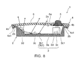
- FIG. 8 is a schematic sectional view of the vehicle interior lighting device 1 according to still another embodiment.
- FIG. 9 is a schematic exploded view of the vehicle interior lighting device 1.
- FIGS. 10A and 10B are schematic diagrams for illustrating disposing forms of light-emitting elements 3b1 and 3b2.
- the light-emitting section 3 includes the substrate 3a, the light-emitting element 3b1 (equivalent to an example of the first light-emitting element), the light-emitting element 3b2 (equivalent to an example of the second light-emitting element), the switch 3c, and the control section 3d.
- a part of lights irradiated from the light-emitting element 3b1 and the light-emitting element 3b2 is made incident on the side surface 2d.
- the light made incident on the side surface 2d is reflected and irradiated to the outside of the vehicle interior lighting device 1 via the cover 6.
- Pluralities of the light-emitting elements 3b1 and 3b2 are provided on the substrate 3a.
- the light-emitting elements 3b1 and 3b2 can be, for example, light-emitting diodes or laser diodes.
- the numbers of the light-emitting elements 3b1 and 3b2 are not particularly limited.
- the numbers of the light-emitting elements 3b1 and 3b2 can be changed as appropriate according to the use, the size, and the like of the vehicle interior lighting device 1. That is, the numbers of the light-emitting elements 3b1 and 3b2 only have to be two or more.
- At least any one of a light-emitting color, chromaticity, and color temperature of lights irradiated from the light-emitting elements 3b1 can be set different from at least any one of a light-emitting color, chromaticity, and color temperature of lights irradiated from the light-emitting elements 3b2.
- the light-emitting colors, the chromaticities, and the color temperatures can be set different by changing semiconductor materials forming the light-emitting elements 3b1 and 3b2 or can be set different by changing phosphors provided on emission surfaces of the light-emitting elements 3b1 and 3b2.
- the arrangement of the pluralities of light-emitting elements 3b1 and 3b2 may be regular arrangement such as a matrix shape or a concentric circle shape or may be any arrangement.
- the light-emitting elements 3b1 and the light-emitting elements 3b2 contiguous to each other as shown in FIG. 10A and alternately arrange the light-emitting elements 3b1 and the light-emitting elements 3b2 as shown in FIG. 10B .
- the ON mode is a mode for lighting at least a part of the pluralities of light-emitting elements 3b1 and 3b2.
- An OFF mode is a mode for extinguishing the pluralities of light-emitting elements 3b1 and 3b2.
- the DOOR mode is a mode for lighting at least a part of the pluralities of light-emitting elements 3b1 and 3b2 when a door of a vehicle is in an open state and extinguishing the pluralities of the light-emitting elements 3b1 and 3b2 when doors of the vehicle are in a closed state.
- a connection method for the light-emitting elements 3b1 and 3b2 and a not-shown wiring pattern provided on the surface of the substrate 3a is not particularly limited.
- the light-emitting elements 3b1 and 3b2 can be electrically connected to the not-shown wiring pattern via a wire.
- the light-emitting elements 3b1 and 3b2 may be mounted by COB (Chip On Board) directly connected to the not-shown wiring pattern.
- the light-emitting elements 3b1 and 3b2 can be directly provided on the substrate 3a or can be provided on the substrate 3a via an envelope like, for example, a PLCC (Plastic Leaded Chip Carrier) type.
- PLCC Poly Leaded Chip Carrier
- annular reflectors surrounding the light-emitting elements 3b1 and 3b2 can be provided, the light-emitting elements 3b1 and 3b2 can be sealed by resin, or phosphors can be included in the resin for sealing the light-emitting elements 3b1 and 3b2.
- the control section 3d controls light-emitting states of the pluralities of the light-emitting elements 3b1 and 3b2 to set at least any one of a light-emitting color, chromaticity, and color temperature in the ON mode and at least any one of a light-emitting color, chromaticity, and color temperature in the DOOR mode to be different from each other.
- the control section 3d can also control the light-emitting states of the pluralities of light-emitting elements 3b1 and 3b2 to set a lighting pattern in the ON mode and the lighting pattern in the DOOR mode to be different from each other.
- the control section 3d can also control the light-emitting states of the pluralities of light-emitting elements 3b1 and 3b2 to set a light-emitting region in the ON mode and a light-emitting region in the DOOR mode to be different from each other.
- the control section 3d controls the light-emitting states of the pluralities of the light-emitting elements 3b1 and 3b2 to set at least any one of the light-emitting color, the chromaticity, and the color temperature in the ON mode and at least any one of the light-emitting color, the chromaticity, and the color temperature to be different from each other.
- control section 3d can set at least any one of the light-emitting color, the chromaticity, and the color temperature in the ON mode and at least any one of the light-emitting color, the chromaticity, and the color temperature to be different from each other by, for example, lighting any ones of the light-emitting elements 3b1 and the light-emitting elements 3b2 or changing the number and an amount of light of the light-emitting elements 3b1 to be lit and the number and an amount of light of the light-emitting elements 3b2 to be lit.
- control section 3d can change the amounts of light by changing current amounts applied to the light-emitting elements 3b1 and 3b2.
- Purposes of lighting in the ON mode are improvement of comfortableness in the vehicle interior, improvement of visibility in hand work of the passenger, improvement of safety, and the like.
- Purposes of lighting in the DOOR mode are improvement of visibility in getting on and off the vehicle, improvement of visibility from other vehicles, and the like.
- the control section 3d can control the light-emitting states of the pluralities of light-emitting elements 3b1 and 3b2 to set a lighting pattern in the ON mode and a lighting pattern in the DOOR mode to be different from each other.
- control section 3d can also control the light-emitting states of the plurality of light-emitting elements 3b1 and 3b2 to set a light-emitting region in the ON mode and a light-emitting region in the DOOR mode to be different from each other.
- the control section 3d can light the light-emitting elements 3b1 and 3b2 corresponding to the light-emitting regions to set the light-emitting region in the ON mode and the light-emitting region in the DOOR mode to be different from each other.
- the number of light-emitting regions is not limited to two. A plurality of light-emitting regions only have to be provided.
- the number of the light-emitting regions it is possible to set the number of the light-emitting regions to the number same as the number of the doors of the vehicle and provide the light-emitting regions respectively corresponding to the plurality of doors.
- the cover 6 can also be divided to match the light-emitting regions.
- FIGS. 11A and 11B are schematic views for illustrating the light-emitting region in the ON mode and the light-emitting region in the DOOR mode set different from each other.
- FIG. 8B is a schematic sectional view in a B-B line direction in FIG. 8A .
- the light-emitting region can be divided into the frame-like light-emitting region 16e provided in a peripheral edge portion of the cover 6 and the planar light-emitting region 16f provided in the center of the cover 6.
- an end section on a light incident side of the light guide section 6b is provided right above the light-emitting elements 3b1 and 3b2 provided at the peripheral edge of the substrate 3a.
- the end section on the light incident side of the light guide section 6b faces a part of the pluralities of light-emitting elements 3b1 and 3b2.
- the light guide section 6b, the portion corresponding to the light-emitting region 16e of the cover 6, and the portion corresponding to the light-emitting region 16f of the cover 6 can be joined by a two-color molding method or fitting.
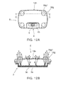
- FIGS. 12A and 12B are schematic diagrams for illustrating a light-emitting region in the ON mode and a light-emitting region in the DOOR mode set different from each other.
- FIG. 12B is a schematic sectional view in a C-C line direction in FIG. 12A .
- the light-emitting region can be divided into light-emitting regions 16g provided at the four corners of the cover 6 and a planar light-emitting region 16h provided mainly in the center of the cover 6.
- the light-emitting elements 3b1 and 3b2 are possible to light the light-emitting elements 3b1 and 3b2 to only in the light-emitting region 16h or in the light-emitting region 16h and the light-emitting regions 16g.
- Optical elements 16g1 can be provided in the light-emitting regions 16g.
- the optical elements 16g1 can be, for example, convex lenses illustrated in FIG. 12B .
- the optical elements 16g1 are not limited to the convex lenses and only have to be optical elements that can generate a desired light condensation characteristic (condense lights in a predetermined position) or generate a desired luminous intensity distribution characteristic (cause desired spread of light).
- the optical elements 16g1 are the convex lenses, it is easy to condense lights in the vicinities of the doors of the vehicle and in the vicinities of seats.
- the light-emitting regions 16g are provided at the four corners of the cover 6.
- the light-emitting regions 16g are not limited to this.
- the number, the shape, the disposing positions, and the like of the light-emitting regions 16g can be changed as appropriate according to the use of the vehicle interior lighting device, the design of interior materials in the vehicle interior, and the like.
- the number of the light-emitting regions 16g can be set the same as the number of the doors of the vehicle.
- the light-emitting regions 16g can be respectively provided for the plurality of doors.
- the optical elements can be provided in at least one of the light-emitting region 16h and the light-emitting regions 16g.
Landscapes
- Engineering & Computer Science (AREA)
- Mechanical Engineering (AREA)
- General Engineering & Computer Science (AREA)
- Microelectronics & Electronic Packaging (AREA)
- Arrangements Of Lighting Devices For Vehicle Interiors, Mounting And Supporting Thereof, Circuits Therefore (AREA)
Abstract
Description
- Embodiments described herein relate to a vehicle interior lighting device.
- There is a vehicle interior lighting device including a light-emitting diode as a light source and provided in the interior of an automobile.
- Such a vehicle interior lighting device includes a switch for switching an ON mode for lighting the light-emitting diode, an OFF mode for extinguishing the light-emitting diode, and a DOOR mode for lighting the light-emitting diode when a door of the vehicle is in an open state and extinguishing the light-emitting diode when doors of the vehicle are in a closed state.
- The vehicle interior lighting device distinguishes the modes according to states of an operation section of the switch.
- However, it is hard to see the states of the operation section. For example, it is likely that a passenger mistakes the ON mode for the DOOR mode and leaves the vehicle and the light-emitting diode is left in a lit state.
- There is proposed a vehicle interior lighting device in which an amount of light of a bulb in the DOOR mode is less than an amount of light of the bulb in the ON mode.
- However, if the amount of light of the bulb in the DOOR mode is reduced, it is likely that the safety in getting on and off the vehicle is deteriorated.
-
-
FIG. 1 is a schematic view for illustrating a vehicle interior lighting device according to an embodiment; -
FIG. 2 is a schematic sectional view of the vehicle interior lighting device; -
FIG. 3 is a schematic exploded view of the vehicle interior lighting device; -
FIGS. 4A to 4C are schematic views for illustrating switching of modes; -
FIG. 5 is a schematic perspective view for illustrating an operation section according to another embodiment; -
FIG. 6A is a schematic view for illustrating a light-emitting region in an ON mode and a light-emitting region in a DOOR mode set different from each other; -
FIG. 6B is a schematic sectional view in a B-B line direction inFIG. 6A ; -
FIGS. 7A and 7B are schematic views for illustrating the light-emitting region in the ON mode and the light-emitting region in the DOOR mode set different from each other; -
FIG. 8 is a schematic sectional view of a vehicle interior lighting device according to still another embodiment; -
FIG. 9 is a schematic exploded view of the vehicle interior lighting device; -
FIGS. 10A and 10B are schematic views for illustrating disposing forms of light-emitting elements; -
FIG. 11A is a schematic view for illustrating a light-emitting region in an ON mode and a light-emitting region in a DOOR mode set different from each other; -
FIG. 11B is a schematic sectional view in a B-B line direction inFIG. 11A ; -
FIG. 12A is a schematic view for illustrating the light-emitting region in the ON mode and the light-emitting region in the DOOR mode set different from each other; and -
FIG. 12B is a schematic sectional view in a C-C line direction inFIG. 12A . - In general, according to one embodiment, there is provided a vehicle interior lighting device including: a plurality of light-emitting elements; a switch for switching an ON mode for lighting at least a part of the plurality of light-emitting elements and a DOOR mode for lighting at least a part of the plurality of light-emitting elements when a door of a vehicle is in an open state and extinguishing the plurality of light-emitting elements when doors of the vehicle are in a closed state; and a control section configured to control light-emitting states of the plurality of light-emitting elements to set an amount of light in the DOOR mode to be more than an amount of light in the ON mode.
- With the vehicle interior lighting device, it is possible to easily distinguish the ON mode and the DOOR mode and improve the safety in getting on and off the vehicle.
- The control section can control the light-emitting states of the plurality of light-emitting elements to further set a lighting pattern in the ON mode and a lighting pattern in the DOOR mode to be different from each other.
- Consequently, it is possible to more easily distinguish the ON mode and the DOOR mode and further improve the safety in getting on and off the vehicle.
- It is also possible to perform lighting rendition.
- The control section can control the light-emitting states of the plurality of light-emitting elements to further set a light-emitting region in the ON mode and a light-emitting region in the DOOR mode to be different from each other.
- Consequently, it is possible to more easily distinguish the ON mode and the DOOR mode and further improve the safety during getting on and getting off.
- It is also possible to perform lighting rendition.
- In this case, the transmittance of light of a first member provided in the light-emitting region in the ON mode can be set different from the transmittance of light of a second member provided in the light-emitting region in the DOOR mode.
- Consequently, it is possible to more easily distinguish the ON mode and the DOOR mode and further improve the safety during getting on and getting off.
- It is also possible to perform more sophisticated lighting rendition.
- The first member and the second member can be joined by a two-color molding method or fitting. An end section on a light incident side of the second member can be formed to face a part of the plurality of light-emitting elements.
- Consequently, it is possible to more easily distinguish the ON mode and the DOOR mode and further improve the safety during getting on and getting off.
- It is also possible to perform more sophisticated lighting rendition.
- According to another embodiment, there is provided a vehicle interior lighting device including: a plurality of first light-emitting elements; a plurality of second light-emitting elements; a switch for switching an ON mode for lighting at least a part of the plurality of first light-emitting elements and the plurality of second light-emitting elements and a DOOR mode for lighting at least a part of the plurality of first light-emitting elements and the plurality of second light-emitting elements when a door of a vehicle is in an open state and extinguishing the plurality of first light-emitting elements and the plurality of second light-emitting elements when doors of the vehicle are in a closed state; and a control section configured to control light-emitting states of the plurality of first light-emitting elements and the plurality of second light-emitting elements to set at least any one of a light-emitting color, chromaticity, and color temperature in the ON mode and at least any one of a light-emitting color, chromaticity, and color temperature in the DOOR mode to be different from each other.
- With the vehicle-interior lighting device, it is possible to easily distinguish the ON mode and the DOOR mode.
- The control section can control light-emitting states of the plurality of first light-emitting elements and the plurality of second light-emitting elements to further set a lighting pattern in the ON mode and a lighting pattern in the DOOR mode to be different from each other.
- Consequently, it is possible to more easily distinguish the ON mode and the DOOR mode.
- It is also possible to perform lighting rendition.
- The control section can control light-emitting states of the plurality of first light-emitting elements and the plurality of second light-emitting elements to further set a light-emitting region in the ON mode and a light-emitting region in the DOOR mode to be different from each other.
- Consequently, it is possible to more easily distinguish the ON mode and the DOOR mode.
- It is also possible to perform lighting rendition.
- In this case, the transmittance of light of a first member provided in the light-emitting region in the ON mode can be set different from the transmittance of light of a second member provided in the light-emitting region in the DOOR mode.
- Consequently, it is possible to more easily distinguish the ON mode and the DOOR mode.
- It is also possible to perform more sophisticated lighting rendition.
- The first member and the second member can be joined by a two-color molding method or fitting. An end section on a light incident side of the second member can be formed to face a part of the plurality of first light-emitting elements and the plurality of second light-emitting elements.
- Consequently, it is possible to more easily distinguish the ON mode and the DOOR mode.
- It is also possible to perform more sophisticated lighting rendition.
- According to still another embodiment, there is provided a vehicle interior lighting device including: a plurality of light-emitting elements; a switch for switching an ON mode for lighting at least a part of the plurality of light-emitting elements and a DOOR mode for lighting at least a part of the plurality of light-emitting elements when a door of a vehicle is in an open state and extinguishing the plurality of light-emitting elements when doors of the vehicle are in a closed state; and a control section configured to control light-emitting states of the plurality of light-emitting elements to set a light-emitting region in the ON mode and a light-emitting region in the DOOR mode to be different from each other.
- With the vehicle interior lighting device, it is possible to easily distinguish the ON mode and the DOOR mode.
- The vehicle interior lighting device can further include an optical element provided in at least one of the light-emitting region in the ON mode and the light-emitting region in the DOOR mode and configured to generate a desired light condensation characteristic and a desired luminous intensity distribution characteristic.
- Consequently, it is possible to more easily distinguish the ON mode and the DOOR mode.
- It is also possible to perform lighting rendition.
- The control section can control light-emitting states of the plurality of light-emitting elements to cause the plurality of light-emitting elements to irradiate light on an entire vehicle interior in the ON mode and irradiate light on at least one of the vicinities of the doors of the vehicle and the vicinities of seats in the DOOR mode.
- Consequently, it is possible to perform irradiation of light corresponding to a purpose of lighting in the ON mode and a purpose of lighting in the DOOR mode.
- It is also possible to perform lighting rendition.
- The transmittance of light of a first member provided in the light-emitting region in the ON mode can be set different from the transmittance of light of a second member provided in the light-emitting region in the DOOR mode.
- Consequently, it is possible to further improve distinction for the DOOR mode.
- It is also possible to perform more sophisticated lighting rendition.
- The first member and the second member can be joined by a two-color molding method or fitting. An end section on a light incident side of the second member can be formed to face a part of the plurality of light-emitting elements.
- Consequently, it is possible to further improve the distinction for the DOOR mode.
- It is also possible to perform more sophisticated lighting rendition.
- The control section can control light-emitting states of the plurality of light-emitting elements to further set at least any one of a light-emitting color, chromaticity, color temperature, and an amount of light in the ON mode and at least any one of a light-emitting color, chromaticity, color temperature, and an amount of light in the DOOR mode to be different from each other.
- Consequently, it is possible to easily distinguish the ON mode and the DOOR mode.
- It is also possible to perform more sophisticated lighting rendition.
- The control section can control light-emitting states of the plurality of light-emitting elements to further set a lighting pattern in the ON mode and a lighting pattern in the DOOR mode to be different from each other.
- Consequently, it is possible to more easily distinguish the ON mode and the DOOR mode.
- It is also possible to perform more sophisticated lighting rendition.
- Embodiments are illustrated below with reference to the drawings. Note that, in the figures, the same constituent elements are denoted by the same reference numerals and signs and detailed explanation of the constituent elements is omitted as appropriate.
-
FIG. 1 is a schematic perspective view for illustrating a vehicleinterior lighting device 1 according to an embodiment. -
FIG. 2 is a schematic sectional view of the vehicleinterior lighting device 1. - Note that
FIG. 2 is a schematic sectional view in an A-A line direction inFIG. 1 . -
FIG. 3 is a schematic exploded view of the vehicleinterior lighting device 1. -
FIGS. 4A to 4C are schematic views for illustrating switching of modes. - The vehicle
interior lighting device 1 can be provided in, for example, an opening provided on a ceiling surface, a sidewall surface, or the like of the interior of an automobile. - As shown in
FIGS. 1 to 3 , the vehicleinterior lighting device 1 includes ahousing 2, a light-emittingsection 3, aframe 4, anoperation section 5, and acover 6. - The
housing 2 assumes a box shape. Oneend section 2a of thehousing 2 is opened. At theend section 2a of thehousing 2, aflange section 2b projecting toward the outside of thehousing 2 is provided. Theflange section 2b assumes an annular shape and is provided to surround theend section 2a of thehousing 2. - The light-emitting
section 3 is provided on abottom surface 2c on the inside of thehousing 2. - A
side surface 2d on the inside of thehousing 2 is formed as a slope. Theside surface 2d inclines in a direction in which thebottom surface 2c side of theside surface 2d approaches the center side of thehousing 2. - A part of light irradiated from a light-emitting
element 3b is made incident on theside surface 2d. The light made incident on theside surface 2d is reflected and irradiated to the outside of the vehicleinterior lighting device 1 via the cover 6 (seeFIG. 2 ). - For example, when the
side surface 2d is a surface perpendicular to thebottom surface 2c, a part of the light made incident on theside surface 2d is less easily irradiated to the outside of the vehicleinterior lighting device 1. - In this embodiment, the
side surface 2d inclines in the direction in which thebottom surface 2c side of theside surface 2d approaches the center side of thehousing 2. Therefore, the light made incident on theside surface 2d is easily irradiated to the outside of the vehicleinterior lighting device 1. - The material of the
housing 2 is not particularly limited. Thehousing 2 can be formed using, for example, a resin material or a metal material. - In this case, when it is taken into account that a part of the light irradiated from the light-emitting
element 3b is made incident on theside surface 2d, the material of thehousing 2 is preferably a material having high reflectance to the light irradiated from the light-emittingelement 3b. - Examples of the material having high reflectance include white resin and resin mixed with particles of titanium oxide or the like.
- When a heat value of the light-emitting
element 3b or the like provided in the light-emittingsection 3 is large, the material of thehousing 2 is preferably a material having high heat conductivity. - Examples of the material having high heat conductivity include high heat conductivity resin, metal, and ceramics such as aluminum oxide and aluminum nitride.
- Note that the high heat conductivity resin is resin obtained by mixing fibers or particles made of carbon, aluminum oxide, or the like having high heat conductivity in resin of, for example, PET (Polyethyleneterephthalate) or nylon.
- The light-emitting
section 3 includes asubstrate 3a, a light-emittingelement 3b, aswitch 3c, and acontrol section 3d. - The
substrate 3a assumes a tabular shape. A not-shown wiring pattern is provided on the surface of thesubstrate 3a. - The
substrate 3a can be formed of, for example, ceramics such as aluminum oxide or aluminum nitride, an organic material such as paper phenol or glass epoxy, or a metal plate, the surface of which is coated with an insulating material. - Note that, when the surface of the metal plate is coated with the insulating material, the insulating material may be made of an organic material or may be made of an inorganic material.
- When a heat value of the light-emitting
element 3b or the like is large, it is preferable to form thesubstrate 3a using a material having high heat conductivity from the viewpoint of thermal radiation. Examples of the material having high heat conductivity include ceramics such as aluminum oxide and aluminum nitride, the high heat conductivity resin, and a metal plate, the surface of which is coated with an insulator. - The
substrate 3a may be a single layer or a multilayer. - One end of a not-shown power-supply terminal is connected to the not-shown wiring pattern of the
substrate 3a. The other end of the not-shown power-supply terminal is exposed from thehousing 2. An external power supply or the like is connected to the not-shown power-supply terminal exposed from thehousing 2 via a not-shown socket or the like. - A plurality of the light-emitting
elements 3b are provided on thesubstrate 3a. - The light-emitting
elements 3b can be, for example, light-emitting diodes or laser diodes. - The number of the light-emitting
elements 3b is not particularly limited. The number of the light-emittingelements 3b can be changed as appropriate according to the use, the size, and the like of the vehicleinterior lighting device 1. That is, the number of the light-emittingelements 3b only has to be two or more. - The arrangement of the plurality of light-emitting
elements 3b may be regular arrangement such as a matrix shape or a concentric circle shape or may be any arrangement. - A connection method for the light-emitting
elements 3b and the not-shown wiring pattern provided on the surface of thesubstrate 3a is not particularly limited. For example, the light-emittingelements 3b can be electrically connected to the not-shown wiring pattern via a wire. For example, the light-emittingelements 3b may be mounted by COB (Chip On Board) directly connected to the not-shown wiring pattern. - The light-emitting
elements 3b can be directly provided on thesubstrate 3a or can be provided on thesubstrate 3a via an envelope like, for example, a PLCC (Plastic Leaded Chip Carrier) type. - Further, according to necessity, annular reflectors surrounding the light-emitting
elements 3b can be provided, the light-emittingelements 3b can be sealed by resin, or phosphors can be included in the resin for sealing the light-emittingelement 3b. - The
switch 3c is provided on thesubstrate 3a. Theswitch 3c is electrically connected to the not-shown wiring pattern provided on the surface of thesubstrate 3a. - The
switch 3c can be, for example, a slide switch. - As shown in
FIGS. 4A to 4C , a knob 3c1 provided in theswitch 3c is slid to the left and right via theoperation section 5, whereby an ON mode, an OFF mode, and a DOOR mode can be switched. - For example, as shown in
FIG. 4A , theoperation section 5 is slid to the left side to switch the vehicleinterior lighting device 1 to the ON mode. As shown inFIG. 4B , theoperation section 5 is slid to the center to switch the vehicleinterior lighting device 1 to the DOOR mode. As shown inFIG. 4C , theoperation section 5 is slid to the right side to switch the vehicleinterior lighting device 1 to the OFF mode. - Note that the ON mode is a mode for lighting at least a part of the plurality of light-emitting
elements 3b. - The OFF mode is a mode for extinguishing the plurality of light-emitting
elements 3b. - The DOOR mode is a mode for lighting at least a part of the plurality of light-emitting
elements 3b when a door of a vehicle is in an open state and extinguishing the plurality of light-emittingelements 3b when doors of the vehicle are in a closed state. - The
control section 3d is provided on thesubstrate 3a. - The
control section 3d controls light-emitting states of the plurality of light-emittingelements 3b to set an amount of light in the DOOR mode to be more than an amount of light in the ON mode. - The
control section 3d can also control the light-emitting states of the plurality of light-emittingelements 3b to set a lighting pattern in the ON mode and a lighting pattern in the DOOR mode to be different from each other. - The
control section 3d can also control the light-emitting states of the plurality of light-emittingelements 3b to set a light-emitting region in the ON mode and a light-emitting region in the DOOR mode to be different from each other. - The
control section 3d can also control the light-emitting states of the plurality of light-emittingelements 3b to set at least any one of a light-emitting color, chromaticity, color temperature, and an amount of light in the ON mode and at least any one of a light-emitting color, chromaticity, color temperature, and an amount of light in the DOOR mode to be different from each other. - The
control section 3d controls the light-emitting states of the plurality of light-emittingelements 3b to set an amount of light obtained when the doors of the vehicle are in the closed state in the DOOR mode to be equal to or less than a half, one fifth, one tenth, or one hundredth of an amount of light obtained when a door of the vehicle is in the open state. - The
control section 3d can also set the amount of light obtained when the doors of the vehicle are in the closed state in the DOOR mode to be equal to or less than a half, one fifth, one tenth, or one hundredth of an amount of light in the ON mode. - The
control section 3d can be a control circuit including circuit components such as a resistor, a capacitor, and an integrated circuit or can be a control section including an arithmetic element and a storage element and configured to cause the arithmetic element to operate with software stored in the storage element. - Note that details of the
control section 3d are explained below. - The
frame 4 is provided on theend section 2a side (an opening side) of thehousing 2. - The
frame 4 includes anedge section 4a and aretaining section 4b. - The
edge section 4a assumes a frame shape. A claw section 4a1 is provided in theedge section 4a. The distal end of the claw section 4a1 projects toward the center side of theframe 4 to make it possible to retain theflange section 2b of thehousing 2. Theframe 4 is fixed to theend section 2a side of thehousing 2 by the claw section 4a1 (seeFIG. 2 ). - One end of the retaining
section 4b is provided in theedge section 4a. The other end of the retainingsection 4b projects toward the center side of theframe 4. A hole section 4b1 for attaching theoperation section 5 is provided in theretaining section 4b. The hole section 4b1 has a shape extending in a predetermined direction. A not-shown guide section is provided on the inside of the hole section 4b1 to make it possible to retain theoperation section 5 and slide theoperation section 5 along the hole section 4b1. - The
edge section 4a is provided under thecover 6. Therefore, the area of thecover 6, which is an irradiation surface of light, can be increased in size. - That is, according to this embodiment, it is possible to increase an illumination area.
- The retaining
section 4b is exposed from thecover 6. Therefore, by changing the color, the shape, and the like of the retainingsection 4b, it is easy to obtain optimum design of the vehicleinterior lighting device 1 for each of a plurality of kinds of design of interior materials in the vehicle interior. - For example, it is possible to, attaching importance to functions of the vehicle interior lighting device, form the
housing 2 from a material having high light reflectivity or a material having high heat conductivity and, attaching importance to a design property, form theframe 4, which includes the retainingsection 4b exposed from thecover 6, from various materials. - In this case, the material of the
frame 4 can be selected from various materials such as a metal material, a resin material, and ceramics. - Furthermore, by replacing only the
frame 4, it is possible to obtain optimum design of the vehicleinterior lighting device 1 for each of the plurality of kinds of design of the interior materials. - The
operation section 5 is provided on the inside of the hole section 4b1. One end of theoperation section 5 projects from the retainingsection 4b. A not-shown recessed section is provided at the other end of theoperation section 5. The knob 3c1 of theswitch 3c is inserted into the not-shown recessed section. Therefore, by sliding theoperation section 5, it is possible to slide the knob 3c1 of theswitch 3c. - By sliding the
operation section 5 along the hole section 4b1, it is possible to switch the ON mode, the OFF mode, and the DOOR mode. - In this case, the
operation section 5 is retained by the retainingsection 4b. Therefore, it is possible to suppress force applied to theoperation section 5 from being transmitted to theswitch 3c. As a result, it is possible to suppress breakage of theswitch 3c. - The material of the
operation section 5 is not particularly limited. For example, various materials such as a metal material, a resin material, and ceramics can be used. - Note that a slide switch is adopted as the
switch 3c to slide theoperation section 5. However, theswitch 3c and theoperation section 5 are not limited to this. -
FIG. 5 is a schematic perspective view for illustrating anoperation section 5a according to another embodiment. - For example, as shown in
FIG. 5 , a push button switch can also be adopted as theswitch 3c to depress theoperation section 5a. - That is, the
switch 3c and theoperation sections - The
cover 6 is provided on theframe 4. In this case, thecover 6 is provided to cover theedge section 4a of theframe 4 and the opening of theframe 4. - The
cover 6 includes acutout section 6a (seeFIG. 3 ). The retainingsection 4b of theframe 4 is provided on the inside of thecutout section 6a. Therefore, the retainingsection 4b of theframe 4 can be exposed from thecover 6. - The
cover 6 has a curved surface shape convex on the center side. However, the shape of thecover 6 is not limited to the illustrated shape and can be changed as appropriate according to the use of the vehicleinterior lighting device 1, the design of the interior materials in the vehicle interior, and the like. - The
cover 6 is provided to suppress glare. Therefore, the transmittance of light of thecover 6 is set low in order to reduce the intensity of incident light. - For example, the transmittance of light is reduced by applying diffusion treatment such as blasting to at least one of an incident surface and an irradiation surface of the
cover 6 or providing a scattering layer including a scattering material in at least one of the incident surface and the irradiation surface of thecover 6. - The transmittance of light can also be reduced by forming the
cover 6 from a translucent material including the scattering material. - The scattering material can be, for example, a material obtained by adding, to the translucent material, particulates having a refractive index different from the refractive index of the translucent material. The particulates can be, for example, particulates made of titanium oxide.
- In this case, if the linear transmittance of light in the
cover 6 is set to 60% or lower, it is possible to effectively suppress glare. - If the linear transmittance of light in the
cover 6 is set to 30% or higher and 50% or lower, it is possible to more effectively suppress glare without spoiling the functions of the vehicle interior lighting device. - The
control section 3d is further explained. - For example, as illustrated in
FIGS. 4A to 4C , the modes can be switched by operating theoperation section 5. - A passenger can distinguish the modes according to a state of the operation section 5 (e.g., a slide position of the operation section 5).
- However, it is hard to see the state of the
operation section 5. For example, the state of theoperation section 5 is invisible at night and the like. - Therefore, for example, it is likely that the passenger mistakes the ON mode for the DOOR mode and leaves the vehicle and the light-emitting
elements 3b are left in a lit state. - In this case, in order to distinguish the modes, an indicator consisting of a light-emitting diode or the like can also be provided in the vicinity of the
operation section 5. - However, when harmony with the design of the interior materials in the vehicle interior is taken into account, a large indicator cannot be provided.
- Therefore, even if the indicator is provided, it is difficult to distinguish the modes.
- If the indicator is provided, complication of structure and an increase in costs are caused.
- Therefore, the
control section 3d that controls light-emitting states of the plurality of light-emittingelements 3b is provided. - In this case, the
control section 3d controls the light-emitting states of the plurality of light-emittingelements 3b to set an amount of light in the DOOR mode to be more than an amount of light in the ON mode. - The
control section 3d can set the amount of light in the DOOR mode to be more than the amount of light in the ON mode by, for example, changing a current value applied to the plurality of light-emittingelements 3b or changing the number of the light-emittingelements 3b to be lit. - Consequently, even when it is hard to see the state of the
operation section 5 and the indicator, it is possible to easily distinguish the ON mode and the DOOR mode. - Furthermore, it is possible to improve the safety in getting on and off the vehicle.
- The
control section 3d can also control light-emitting states of the plurality of light-emittingelements 3b to set an amount of light obtained when the doors of the vehicle are in the closed state in the DOOR mode to be equal to or less than a half, one fifth, one tenth, or one hundredth of an amount of light obtained when a door of the vehicle is in the open state. - The
control section 3d can also set the amount of light obtained when the doors of the vehicle are in the closed state in the DOOR mode to be equal to or less than a half, one fifth, one tenth, or one hundredth of the amount of light in the ON mode. - Consequently, when the doors of the vehicle is in the closed state, it is seen that the vehicle
interior lighting device 1 is in the DOOR mode if the vehicleinterior lighting device 1 is slightly lit. - Therefore, even when it is hard to see the state of the
operation section 5 and the indicator, it is possible to easily distinguish the ON mode and the DOOR mode. - Furthermore, it is possible to increase an amount of light when the doors of the vehicle are in the open state in the DOOR mode. Therefore, it is possible to improve the safety in getting on and off the vehicle.
- Purposes of lighting in the ON mode are improvement of comfortableness in the vehicle interior, improvement of visibility in hand work of the passenger, improvement of safety, and the like.
- Purposes of lighting in the DOOR mode are improvement of visibility in getting on and off the vehicle, improvement of visibility from other vehicles, and the like.
- Therefore, it is possible to set an amount of light in the ON mode according to a purpose of lighting in the ON mode and set an amount of light in the DOOR mode according to a purpose of lighting in the DOOR mode.
- For example, in the lighting in the ON mode, it is possible to reduce the amount of light taking into account comfortableness in the vehicle interior.
- Note that, in the lighting in the ON mode, it is also possible to increase the amount of light taking into account improvement of visibility in hand work of the passenger, improvement of safety, and the like.
- In the lighting in the DOOR mode, it is possible to increase the amount of light taking into account visibility in getting on and off the vehicle and visibility from other vehicles.
- In order to improve distinction for the DOOR mode, the
control section 3d sets the amount of light obtained when the doors of the vehicle are in the closed state to be equal to or less than a half, one fifth, one tenth, or one hundredth of an amount of light obtained when a door of the vehicle is in the open state. - In this case, if a difference between the amounts of light is too small, the distinction for the DOOR mode is deteriorated.
- According to the knowledge obtained by the inventors, if the amount of light obtained when the doors of the vehicle are in the closed state is set to be equal to or less than a half and, preferably, equal to or less than one fifth of the amount of light obtained when a door of the vehicle is in the open state, it is possible to suppress the distinction for the DOOR mode from being deteriorated.
- In this case, as a difference between the amounts of light is larger, it is possible to more easily distinguish the ON mode and the DOOR mode.
- According to the knowledge obtained by the inventors, the amount of light obtained when the doors of the vehicle are in the closed state is preferably set to be equal to or less than one tenth and more preferable set to be equal to or less than one hundredth of the amount of light obtained when a door of the vehicle is in the open state.
- The
control section 3d can also control the light-emitting states of the plurality of light-emittingelements 3b to set a lighting pattern in the ON mode and a lighting pattern in the DOOR mode to be different from each other. - In this case, it is possible to set the lighting pattern in the ON mode according to a purpose of lighting in the ON mode and set the lighting pattern in the DOOR mode according to a purpose of lighting in the DOOR mode.
- For example, in the lighting in the ON mode, it is possible to perform continuous lighting taking into account comfortableness in the vehicle interior, visibility in hand work, safety, and the like.
- In the lighting in the DOOR mode, it is possible to perform blinking taking into account visibility from other vehicles.
- In the lighting in the DOOR mode, it is also possible to gradually increase or gradually reduce the amount of light from the start of the lighting or increase or reduce the amount of light stepwise.
- Note that, in the lighting in the ON mode, it is also possible to perform blinking or gradually increase or reduce the amount of light from the start of the lighting or increase or reduce the amount of light stepwise from the start of the lighting.
- In this case, it is possible to perform continuous lighting in the lighting in the DOOR mode.
- Consequently, even when it is hard to see the state of the
operation section 5 and the indicator, it is possible to easily distinguish the ON mode and the DOOR mode. - Furthermore, it is also possible to perform lighting rendition.
- The
control section 3d can also control the light-emitting states of the plurality of light-emittingelements 3b to set a light-emitting region in the ON mode and a light-emitting region in the DOOR mode to be different from each other. -
FIGS. 6A and 6B are schematic views for illustrating the light-emitting region in the ON mode and the light-emitting region in the DOOR mode set different from each other. - For example, as shown in
FIG. 6A , the light-emitting region can be divided into a light-emittingregion 16a and a light-emittingregion 16b in the longitudinal direction of thecover 6. - For example, in the lighting in the ON mode, it is possible to light the light-emitting
elements 3b in the light-emittingregion 16a and the light-emittingregion 16b. - In the DOOR mode, it is possible to light the light-emitting
elements 3b in one of the light-emittingregion 16a and the light-emittingregion 16b. - In this case, it is possible to light the light-emitting
elements 3b in the light-emitting region present in a direction where a door of the vehicle opens. - Consequently, it is possible to easily specify the opened door.
- The light-emitting region can be divided into a light-emitting
region 16c and a light-emittingregion 16d in the latitudinal direction of thecover 6. - For example, in the lighting in the ON mode, it is possible to light the light-emitting
elements 3b in the light-emittingregion 16c and the light-emittingregion 16d. - In the lighting in the DOOR mode, it is possible to light the light-emitting
elements 3b in one of the light-emittingregion 16c and the light-emittingregion 16d. - In this case, it is possible to light the light-emitting
elements 3b in the light-emitting region present in a direction where a door of the vehicle opens. - Consequently, it is possible to easily specify the opened door.
- The
control section 3d can light the light-emittingelements 3b corresponding to the light-emitting regions to set the light-emitting region in the ON mode and the light-emitting region in the DOOR mode to be different from each other. - The number of light-emitting regions is not limited to two. A plurality of light-emitting regions only have to be provided.
- In this case, it is possible to set the number of the light-emitting regions to the number same as the number of the doors of the vehicle and provide the light-emitting regions respectively corresponding to the plurality of doors.
- The
control section 3d can also control light-emitting states of the plurality of light-emittingelements 3b to cause the light-emittingelements 3b to irradiate light on the entire vehicle interior in the ON mode and irradiate light at least on the vicinities of the doors of the vehicle and the vicinities of the seats in the DOOR mode. - As illustrated in
FIGS. 6A and 6B , thecover 6 can also be divided to match the light-emitting regions. - However, the division of the
cover 6 is not always necessary and can be performed as appropriate according to necessity of design or the like. -
FIGS. 7A and 7B are also schematic views for illustrating the light-emitting region in the ON mode and the light-emitting region in the DOOR mode set different from each other. - Note that
FIG. 7B is a schematic sectional view in a B-B line direction inFIG. 7A . - As shown in
FIGS. 7A and 7B , the light-emitting region can be divided into a frame-like light-emittingregion 16e provided in a peripheral edge portion of thecover 6 and a planar light-emittingregion 16f provided in the center of thecover 6. - For example, in the lighting in the ON mode, it is possible to light the light-emitting
elements 3b only in the light-emittingregion 16e or in the light-emittingregion 16f and the light-emittingregion 16e. In this case, in the lighting in the DOOR mode, it is possible to light the light-emittingelements 3b only in the light-emittingregion 16e. - In the lighting in the DOOR mode, it is possible to light the light-emitting
elements 3b only in the light-emittingregion 16f or in the light-emittingregion 16f and the light-emittingregion 16e and set an amount of light in the DOOR mode to be larger than an amount of light in the ON mode. - In the lighting in the ON mode, it is possible to light the light-emitting
elements 3b only in the light-emittingregion 16f. In this case, in the lighting in the DOOR mode, it is possible to light the light-emittingelements 3b only in the light-emittingregion 16e where the amount of light in the DOOR mode is adjusted to be higher than the amount of light in the ON mode or in the light-emittingregion 16f and the light-emittingregion 16e. - As shown in
FIG. 7B , alight guide section 6b extending to the inside of thehousing 2 can be provided in the peripheral edge portion of thecover 6. - The
light guide section 6b can be formed from a translucent material. - The transmittance of light of the
light guide section 6b (equivalent to an example of the second member) and the transmittance of light of a portion corresponding to the light-emittingregion 16e of the cover 6 (equivalent to an example of the second member) are different from the transmittance of light of a portion corresponding to the light-emittingregion 16f of the cover 6 (equivalent to an example of the first member). - In this case, the transmittance of light of the
light guide section 6b and the transmittance of light of the portion corresponding to the light-emittingregion 16e of thecover 6 can be set higher than the transmittance of light of the portion corresponding to the light-emittingregion 16f of thecover 6. - An end section on a light incident side of the
light guide section 6b is provided right above the light-emittingelement 3b provided at the peripheral edge of thesubstrate 3a. - That is, the end section on the light incident side of the
light guide section 6b faces a part of the plurality of light-emittingelements 3b. - Therefore, a light amount in the light-emitting
region 16e can be increased. As a result, even when the width dimension of the frame-like light-emittingregion 16e is small, it is possible to increase visibility. - The
light guide section 6b, the portion corresponding to the light-emittingregion 16e of thecover 6, and the portion corresponding to the light-emittingregion 16f of thecover 6 can be joined by a two-color molding method or fitting. - Note that, in the above illustration, the light-emitting region is divided into the frame-like light-emitting
region 16e provided in the peripheral edge portion of thecover 6 and the planar light-emittingregion 16f provided in the center of thecover 6. However, light-emitting regions are not limited to this. - The number of light-emitting regions, the shapes of the light-emitting regions, the sizes of the light-emitting regions, and the like can be changed as appropriate according to the size, the design, the use, and the like of the vehicle
interior lighting device 1. -
FIG. 8 is a schematic sectional view of the vehicleinterior lighting device 1 according to still another embodiment. -
FIG. 9 is a schematic exploded view of the vehicleinterior lighting device 1. -
FIGS. 10A and 10B are schematic diagrams for illustrating disposing forms of light-emitting elements 3b1 and 3b2. - As shown in
FIGS. 8 and9 , the light-emittingsection 3 includes thesubstrate 3a, the light-emitting element 3b1 (equivalent to an example of the first light-emitting element), the light-emitting element 3b2 (equivalent to an example of the second light-emitting element), theswitch 3c, and thecontrol section 3d. - A part of lights irradiated from the light-emitting element 3b1 and the light-emitting element 3b2 is made incident on the
side surface 2d. The light made incident on theside surface 2d is reflected and irradiated to the outside of the vehicleinterior lighting device 1 via thecover 6. - Pluralities of the light-emitting elements 3b1 and 3b2 are provided on the
substrate 3a. - The light-emitting elements 3b1 and 3b2 can be, for example, light-emitting diodes or laser diodes.
- The numbers of the light-emitting elements 3b1 and 3b2 are not particularly limited. The numbers of the light-emitting elements 3b1 and 3b2 can be changed as appropriate according to the use, the size, and the like of the vehicle
interior lighting device 1. That is, the numbers of the light-emitting elements 3b1 and 3b2 only have to be two or more. - At least any one of a light-emitting color, chromaticity, and color temperature of lights irradiated from the light-emitting elements 3b1 can be set different from at least any one of a light-emitting color, chromaticity, and color temperature of lights irradiated from the light-emitting elements 3b2.
- The light-emitting colors, the chromaticities, and the color temperatures can be set different by changing semiconductor materials forming the light-emitting elements 3b1 and 3b2 or can be set different by changing phosphors provided on emission surfaces of the light-emitting elements 3b1 and 3b2.
- The arrangement of the pluralities of light-emitting elements 3b1 and 3b2 may be regular arrangement such as a matrix shape or a concentric circle shape or may be any arrangement.
- However, it is preferable to arrange the light-emitting elements 3b1 and the light-emitting elements 3b2 contiguous to each other as shown in
FIG. 10A and alternately arrange the light-emitting elements 3b1 and the light-emitting elements 3b2 as shown inFIG. 10B . - With such an arrangement form, it is possible to set a luminous intensity distribution characteristic of the vehicle
interior lighting device 1 in an ON mode and a luminous intensity distribution characteristic of the vehicleinterior lighting device 1 in a DOOR mode to be substantially the same. - Note that the ON mode is a mode for lighting at least a part of the pluralities of light-emitting elements 3b1 and 3b2.
- An OFF mode is a mode for extinguishing the pluralities of light-emitting elements 3b1 and 3b2.
- The DOOR mode is a mode for lighting at least a part of the pluralities of light-emitting elements 3b1 and 3b2 when a door of a vehicle is in an open state and extinguishing the pluralities of the light-emitting elements 3b1 and 3b2 when doors of the vehicle are in a closed state.
- A connection method for the light-emitting elements 3b1 and 3b2 and a not-shown wiring pattern provided on the surface of the
substrate 3a is not particularly limited. For example, the light-emitting elements 3b1 and 3b2 can be electrically connected to the not-shown wiring pattern via a wire. For example, the light-emitting elements 3b1 and 3b2 may be mounted by COB (Chip On Board) directly connected to the not-shown wiring pattern. - The light-emitting elements 3b1 and 3b2 can be directly provided on the
substrate 3a or can be provided on thesubstrate 3a via an envelope like, for example, a PLCC (Plastic Leaded Chip Carrier) type. - Further, according to necessity, annular reflectors surrounding the light-emitting elements 3b1 and 3b2 can be provided, the light-emitting elements 3b1 and 3b2 can be sealed by resin, or phosphors can be included in the resin for sealing the light-emitting elements 3b1 and 3b2.
- The
control section 3d controls light-emitting states of the pluralities of the light-emitting elements 3b1 and 3b2 to set at least any one of a light-emitting color, chromaticity, and color temperature in the ON mode and at least any one of a light-emitting color, chromaticity, and color temperature in the DOOR mode to be different from each other. - The
control section 3d can also control the light-emitting states of the pluralities of light-emitting elements 3b1 and 3b2 to set a lighting pattern in the ON mode and the lighting pattern in the DOOR mode to be different from each other. - The
control section 3d can also control the light-emitting states of the pluralities of light-emitting elements 3b1 and 3b2 to set a light-emitting region in the ON mode and a light-emitting region in the DOOR mode to be different from each other. - The
control section 3d controls the light-emitting states of the pluralities of the light-emitting elements 3b1 and 3b2 to set at least any one of the light-emitting color, the chromaticity, and the color temperature in the ON mode and at least any one of the light-emitting color, the chromaticity, and the color temperature to be different from each other. - In this case, the
control section 3d can set at least any one of the light-emitting color, the chromaticity, and the color temperature in the ON mode and at least any one of the light-emitting color, the chromaticity, and the color temperature to be different from each other by, for example, lighting any ones of the light-emitting elements 3b1 and the light-emitting elements 3b2 or changing the number and an amount of light of the light-emitting elements 3b1 to be lit and the number and an amount of light of the light-emitting elements 3b2 to be lit. - Note that the
control section 3d can change the amounts of light by changing current amounts applied to the light-emitting elements 3b1 and 3b2. - Consequently, even when it is hard to see a state of the
operation section 5 and an indicator, it is possible to easily distinguish the ON mode and the DOOR mode. - Purposes of lighting in the ON mode are improvement of comfortableness in the vehicle interior, improvement of visibility in hand work of the passenger, improvement of safety, and the like.
- Purposes of lighting in the DOOR mode are improvement of visibility in getting on and off the vehicle, improvement of visibility from other vehicles, and the like.
- Therefore, it is possible to set at least any one of the light-emitting color, the chromaticity, and the color temperature in the ON mode according to a purpose of lighting in the ON mode and set any one of the light-emitting color, the chromaticity, and the color temperature in the DOOR mode according to a purpose of lighting in the DOOR mode.
- For example, in the lighting in the ON mode, it is possible to irradiate light of a warm color taking into account comfortableness in the vehicle interior.
- In the lighting in the DOOR mode, it is possible to irradiate light of a bluish white color taking into account visibility in getting on and off the vehicle and visibility from other vehicles.
- The
control section 3d can control the light-emitting states of the pluralities of light-emitting elements 3b1 and 3b2 to set a lighting pattern in the ON mode and a lighting pattern in the DOOR mode to be different from each other. - In this case, it is possible to set the lighting pattern in the ON mode according to the purpose of the lighting in the ON mode and set the lighting pattern in the DOOR mode according to the purpose of the lighting in the DOOR mode.
- For example, in the lighting in the ON mode, it is possible to perform continuous lighting taking into account comfortableness in the vehicle interior, visibility in hand work, safety, and the like.
- In the lighting in the DOOR mode, it is possible to perform blinking taking into account visibility from other vehicles.
- In the lighting in the DOOR mode, it is also possible to gradually increase or gradually reduce the amount of light from the start of the lighting or increase or reduce the amount of light stepwise.
- Note that, in the lighting in the ON mode, it is also possible to gradually increase or reduce the amount of light from the start of the lighting or increase or reduce the amount of light stepwise from the start of the lighting.
- In this case, it is possible to perform continuous lighting in the lighting in the DOOR mode.
- Consequently, even when it is hard to see the state of the
operation section 5 and the indicator, it is possible to easily distinguish the ON mode and the DOOR mode. - Furthermore, it is also possible to perform lighting rendition.
- As illustrated in
FIGS. 6A and 6B , thecontrol section 3d can also control the light-emitting states of the plurality of light-emitting elements 3b1 and 3b2 to set a light-emitting region in the ON mode and a light-emitting region in the DOOR mode to be different from each other. - The
control section 3d can light the light-emitting elements 3b1 and 3b2 corresponding to the light-emitting regions to set the light-emitting region in the ON mode and the light-emitting region in the DOOR mode to be different from each other. - The number of light-emitting regions is not limited to two. A plurality of light-emitting regions only have to be provided.
- In this case, it is possible to set the number of the light-emitting regions to the number same as the number of the doors of the vehicle and provide the light-emitting regions respectively corresponding to the plurality of doors.
- As shown in
FIGS. 6A and 6B , thecover 6 can also be divided to match the light-emitting regions. - However, the division of the
cover 6 is not always necessary and can be performed as appropriate according to necessity of design or the like. -
FIGS. 11A and 11B are schematic views for illustrating the light-emitting region in the ON mode and the light-emitting region in the DOOR mode set different from each other. - Note that
FIG. 8B is a schematic sectional view in a B-B line direction inFIG. 8A . - As shown in
FIGS. 11A and 11B , the light-emitting region can be divided into the frame-like light-emittingregion 16e provided in a peripheral edge portion of thecover 6 and the planar light-emittingregion 16f provided in the center of thecover 6. - For example, an end section on a light incident side of the
light guide section 6b is provided right above the light-emitting elements 3b1 and 3b2 provided at the peripheral edge of thesubstrate 3a. - That is, the end section on the light incident side of the
light guide section 6b faces a part of the pluralities of light-emitting elements 3b1 and 3b2. - Therefore, a light amount in the light-emitting
region 16e can be increased. As a result, even when the width dimension of the frame-like light-emittingregion 16e is small, it is possible to increase visibility. - The
light guide section 6b, the portion corresponding to the light-emittingregion 16e of thecover 6, and the portion corresponding to the light-emittingregion 16f of thecover 6 can be joined by a two-color molding method or fitting. -
FIGS. 12A and 12B are schematic diagrams for illustrating a light-emitting region in the ON mode and a light-emitting region in the DOOR mode set different from each other. - Note that
FIG. 12B is a schematic sectional view in a C-C line direction inFIG. 12A . - As shown in
FIGS. 12A and 12B , the light-emitting region can be divided into light-emittingregions 16g provided at the four corners of thecover 6 and a planar light-emittingregion 16h provided mainly in the center of thecover 6. - For example, in the lighting in the ON mode, it is possible to light the light-emitting elements 3b1 and 3b2 to only in the light-emitting
region 16h or in the light-emittingregion 16h and the light-emittingregions 16g. - In the lighting in the DOOR mode, it is possible to light the light-emitting elements 3b1 and 3b2 only in the light-emitting
regions 16g. - Optical elements 16g1 can be provided in the light-emitting
regions 16g. - The optical elements 16g1 can be, for example, convex lenses illustrated in
FIG. 12B . The optical elements 16g1 are not limited to the convex lenses and only have to be optical elements that can generate a desired light condensation characteristic (condense lights in a predetermined position) or generate a desired luminous intensity distribution characteristic (cause desired spread of light). - However, if the optical elements 16g1 are the convex lenses, it is easy to condense lights in the vicinities of the doors of the vehicle and in the vicinities of seats.
- Therefore, it is possible to easily distinguish the ON mode and the DOOR mode and improve visibility and safety in getting on and off the vehicle.
- It is also possible to perform lighting rendition.
- Note that, in the above illustration, the light-emitting
regions 16g are provided at the four corners of thecover 6. However, the light-emittingregions 16g are not limited to this. - The number, the shape, the disposing positions, and the like of the light-emitting
regions 16g can be changed as appropriate according to the use of the vehicle interior lighting device, the design of interior materials in the vehicle interior, and the like. - In this case, the number of the light-emitting
regions 16g can be set the same as the number of the doors of the vehicle. The light-emittingregions 16g can be respectively provided for the plurality of doors. - The optical elements can be provided in at least one of the light-emitting
region 16h and the light-emittingregions 16g. - While certain embodiments have been described, these embodiments have been presented by way of example only, and are not intended to limit the scope of the inventions. Indeed, the novel embodiments described herein may be embodied in a variety of other forms; furthermore, various omissions, substitutions and changes in the form of the embodiments described herein may be made without departing from the spirit of the inventions. The accompanying claims and their equivalents are intended to cover such forms or modifications as would fall within the scope and spirit of the inventions. Moreover, above-mentioned embodiments can be combined mutually and can be carried out.
Claims (17)
- A vehicle interior lighting device (1) comprising:a plurality of light-emitting elements (3b);a switch (3c) for switching an ON mode for lighting at least a part of the plurality of light-emitting elements (3b) and a DOOR mode for lighting at least a part of the plurality of light-emitting elements (3b) when a door of a vehicle is in an open state and extinguishing the plurality of light-emitting elements (3b) when doors of the vehicle are in a closed sate; anda control section (3d) configured to control light-emitting states of the plurality of light-emitting elements (3b) to set an amount of light in the DOOR mode to be more than an amount of light in the ON mode.
- The device (1) according to claim 1, wherein the control section (3d) controls the light-emitting states of the plurality of light-emitting elements (3b) to further set a lighting pattern in the ON mode and a lighting pattern in the DOOR mode to be different from each other.
- The device (1) according to claim 1 or 2, wherein the control section (3d) controls the light-emitting states of the plurality of light-emitting elements (3b) to further set a light-emitting region in the ON mode and a light-emitting region in the DOOR mode to be different from each other.
- The device (1) according to claim 3, wherein transmittance of light of a first member (16f) provided in the light-emitting region in the ON mode is set different from transmittance of light of a second member (6a, 16e) provided in the light-emitting region in the DOOR mode.
- The device (1) according to claim 4, wherein
the first member (16f) and the second member (6a, 16a) are joined by a two-color molding method or fitting, and
an end section on a light incident side of the second member (6a, 16e) is formed to face a part of the plurality of light-emitting elements (3b). - A vehicle interior lighting device (1) comprising:a plurality of first light-emitting elements (3b1);a plurality of second light-emitting elements (3b2);a switch (3c) for switching an ON mode for lighting at least a part of the plurality of first light-emitting elements (3b1) and the plurality of second light-emitting elements (3b2) and a DOOR mode for lighting at least a part of the plurality of first light-emitting elements (3b1) and the plurality of second light-emitting elements (3b2) when a door of a vehicle is in an open state and extinguishing the plurality of first light-emitting elements (3b1) and the plurality of second light-emitting elements (3b2) when doors of the vehicle are in a closed sate; anda control section (3d) configured to control light-emitting states of the plurality of first light-emitting elements (3b1) and the plurality of second light-emitting elements (3b2) to set at least any one of a light-emitting color, chromaticity, and color temperature in the ON mode and at least any one of a light-emitting color, chromaticity, and color temperature in the DOOR mode to be different from each other.
- The device (1) according to claim 6, wherein the control section (3d) controls light-emitting states of the plurality of first light-emitting elements (3b1) and the plurality of second light-emitting elements (3b2) to further set a lighting pattern in the ON mode and a lighting pattern in the DOOR mode to be different from each other.
- The device (1) according to claim 6 or 7, wherein the control section (3d) controls light-emitting states of the plurality of first light-emitting elements (3b1) and the plurality of second light-emitting elements (3b2) to further set a light-emitting region in the ON mode and a light-emitting region in the DOOR mode to be different from each other.
- The device (1) according to claim 8, wherein transmittance of light of a first member (16f) provided in the light-emitting region in the ON mode is set different from transmittance of light of a second member (6a, 16e) provided in the light-emitting region in the DOOR mode.
- The device (1) according to claim 9, wherein
the first member (16f) and the second member (6a, 16e) are joined by a two-color molding method or fitting, and
an end section on a light incident side of the second member (6a, 16e) is formed to face a part of the plurality of first light-emitting elements (3b1) and the plurality of second light-emitting elements (3b2). - A vehicle interior lighting device (1) comprising:a plurality of light-emitting elements (3b);a switch (3c) for switching an ON mode for lighting at least a part of the plurality of light-emitting elements (3b) and a DOOR mode for lighting at least a part of the plurality of light-emitting elements (3b) when a door of a vehicle is in an open state and extinguishing the plurality of light-emitting elements (3b) when doors of the vehicle are in a closed sate; anda control section (3d) configured to control light-emitting states of the plurality of light-emitting elements (3b) to set a light-emitting region in the ON mode and a light-emitting region in the DOOR mode to be different from each other.
- The device (1) according to claim 11, further comprising an optical element (16g1) provided in at least one of the light-emitting region in the ON mode and the light-emitting region in the DOOR mode and configured to generate at least one of a desired light condensation characteristic and a desired luminous intensity distribution characteristic.
- The device (1) according to claim 11 or 12, wherein the control section (3d) controls light-emitting states of the plurality of light-emitting elements (3b) to cause the plurality of light-emitting elements (3b) to irradiate light on an entire vehicle interior in the ON mode and irradiate light on at least one of the vicinities of the doors of the vehicle and the vicinities of seats in the DOOR mode.
- The device (1) according to any one of claims 11 to 13, wherein transmittance of light of a first member (16f) provided in the light-emitting region in the ON mode is set different from transmittance of light of a second member (6a, 16e) provided in the light-emitting region in the DOOR mode.
- The device (1) according to claim 14, wherein
the first member (16f) and the second member (6a, 16e) are joined by a two-color molding method or fitting, and
an end section on a light incident side of the second member (6a, 16e) is formed to face a part of the plurality of light-emitting elements (3b). - The device (1) according to any one of claims 11 to 15, wherein the control section (3d) controls light-emitting states of the plurality of light-emitting elements (3b) to further set at least any one of a light-emitting color, chromaticity, color temperature, and an amount of light in the ON mode and at least any one of a light-emitting color, chromaticity, color temperature, and an amount of light in the DOOR mode to be different from each other.
- The device (1) according to any one of claims 11 to 16, wherein the control section (3d) controls light-emitting states of the plurality of light-emitting elements (3b) to further set a lighting pattern in the ON mode and a lighting pattern in the DOOR mode to be different from each other.
Applications Claiming Priority (4)
| Application Number | Priority Date | Filing Date | Title |
|---|---|---|---|
| JP2014062209A JP6252984B2 (en) | 2014-03-25 | 2014-03-25 | Car interior lighting system |
| JP2014062723A JP6252985B2 (en) | 2014-03-25 | 2014-03-25 | Car interior lighting system |
| JP2014062722A JP2015182691A (en) | 2014-03-25 | 2014-03-25 | Vehicle interior lighting device |
| JP2014062448A JP2015182678A (en) | 2014-03-25 | 2014-03-25 | Vehicle interior lighting device |
Publications (2)
| Publication Number | Publication Date |
|---|---|
| EP2923891A2 true EP2923891A2 (en) | 2015-09-30 |
| EP2923891A3 EP2923891A3 (en) | 2015-11-04 |
Family
ID=52423631
Family Applications (1)
| Application Number | Title | Priority Date | Filing Date |
|---|---|---|---|
| EP15152982.3A Withdrawn EP2923891A3 (en) | 2014-03-25 | 2015-01-29 | Vehicle interior lighting device |
Country Status (3)
| Country | Link |
|---|---|
| US (1) | US20150274070A1 (en) |
| EP (1) | EP2923891A3 (en) |
| CN (1) | CN104949026A (en) |
Cited By (2)
| Publication number | Priority date | Publication date | Assignee | Title |
|---|---|---|---|---|
| FR3047941A1 (en) * | 2016-02-24 | 2017-08-25 | Valeo Vision | LIGHTING SYSTEM FOR THE CABIN OF A MOTOR VEHICLE |
| FR3047946A1 (en) * | 2016-02-24 | 2017-08-25 | Valeo Vision | READER, IN PARTICULAR FOR THE CABINET OF A MOTOR VEHICLE |
Families Citing this family (6)
| Publication number | Priority date | Publication date | Assignee | Title |
|---|---|---|---|---|
| US9789823B2 (en) * | 2015-11-03 | 2017-10-17 | Ford Global Technologies Llc | Illuminated tiered cargo area storage for vehicle |
| CN105650570B (en) * | 2016-03-31 | 2018-02-06 | 常州星宇车灯股份有限公司 | Automobile room lamp based on capacitive touch switch |
| JP6526611B2 (en) * | 2016-10-07 | 2019-06-05 | 矢崎総業株式会社 | Car interior lighting device |
| DE102017205789B4 (en) * | 2017-04-05 | 2022-04-21 | Volkswagen Aktiengesellschaft | Interior light for a motor vehicle |
| CN110949249B (en) * | 2019-11-28 | 2021-10-26 | 中国第一汽车股份有限公司 | Control method, regulation method and control system for automobile indoor lamp |
| CN114340082B (en) * | 2021-12-20 | 2023-12-26 | 华人运通(江苏)技术有限公司 | Door trim lighting system, control method, storage medium and vehicle |
Family Cites Families (8)
| Publication number | Priority date | Publication date | Assignee | Title |
|---|---|---|---|---|
| JP3959917B2 (en) * | 1999-06-28 | 2007-08-15 | 豊田合成株式会社 | Vehicle interior lighting device |
| US6851841B2 (en) * | 2001-11-28 | 2005-02-08 | Toyoda Gosei Co., Ltd. | Illumination device |
| JP4013562B2 (en) * | 2002-01-25 | 2007-11-28 | 豊田合成株式会社 | Lighting device |
| JP4029077B2 (en) * | 2004-03-31 | 2008-01-09 | 株式会社ホンダアクセス | Automotive interior lighting equipment |
| JP4706598B2 (en) * | 2006-08-24 | 2011-06-22 | 市光工業株式会社 | Vehicle room lamp |
| JP4572895B2 (en) * | 2006-12-20 | 2010-11-04 | 市光工業株式会社 | Vehicle room lamp |
| JP5017029B2 (en) * | 2007-09-12 | 2012-09-05 | 矢崎総業株式会社 | Interior lighting for vehicles |
| JP5338637B2 (en) * | 2009-11-24 | 2013-11-13 | トヨタ紡織株式会社 | Vehicle interior light |
-
2015
- 2015-01-28 CN CN201510044112.1A patent/CN104949026A/en active Pending
- 2015-01-29 EP EP15152982.3A patent/EP2923891A3/en not_active Withdrawn
- 2015-01-30 US US14/609,943 patent/US20150274070A1/en not_active Abandoned
Non-Patent Citations (1)
| Title |
|---|
| None |
Cited By (4)
| Publication number | Priority date | Publication date | Assignee | Title |
|---|---|---|---|---|
| FR3047941A1 (en) * | 2016-02-24 | 2017-08-25 | Valeo Vision | LIGHTING SYSTEM FOR THE CABIN OF A MOTOR VEHICLE |
| FR3047946A1 (en) * | 2016-02-24 | 2017-08-25 | Valeo Vision | READER, IN PARTICULAR FOR THE CABINET OF A MOTOR VEHICLE |
| EP3210828A1 (en) * | 2016-02-24 | 2017-08-30 | Valeo Vision | Lighting system for the passenger compartment of a motor vehicle |
| US10399487B2 (en) | 2016-02-24 | 2019-09-03 | Valeo Vision | Lighting system for motor vehicle passenger compartment |
Also Published As
| Publication number | Publication date |
|---|---|
| EP2923891A3 (en) | 2015-11-04 |
| CN104949026A (en) | 2015-09-30 |
| US20150274070A1 (en) | 2015-10-01 |
Similar Documents
| Publication | Publication Date | Title |
|---|---|---|
| EP2923891A2 (en) | Vehicle interior lighting device | |
| US5452190A (en) | Optoelectronic component | |
| EP2458266B1 (en) | Light emitting diode (LED) lamp | |
| EP3425023B1 (en) | White light emitting devices | |
| US20120008305A1 (en) | Solid state lighting system with optic providing occluded remote phosphor | |
| US20080130305A1 (en) | LED Lights for Interior Automotive Lighting | |
| US9057497B2 (en) | LED module having a double diffuser | |
| US9409514B2 (en) | Light device with frame provided for holding switch operating section | |
| US7665869B2 (en) | Light for the passenger compartment of a motor vehicle | |
| US7661859B2 (en) | Operation panel | |
| US8403551B2 (en) | Lighting device | |
| US9512981B2 (en) | Luminaire for interior lamp provided in automobile | |
| JP6252984B2 (en) | Car interior lighting system | |
| US9821712B2 (en) | Vehicle interior lighting device | |
| JP6252985B2 (en) | Car interior lighting system | |
| KR20100009796A (en) | Automobile vanity mirror apparatus | |
| JP2548886B2 (en) | Optoelectronic device | |
| JP2015182678A (en) | Vehicle interior lighting device | |
| JP2015182691A (en) | Vehicle interior lighting device | |
| JP6683944B2 (en) | Vehicle interior operation switch | |
| JP2009241664A (en) | Vehicular lighting system | |
| JP6667139B2 (en) | Interior lighting system | |
| WO2026053721A1 (en) | Lighting device | |
| JP2018099951A (en) | Vehicle cabin internal lighting device | |
| CN108877573A (en) | Pattern luminescent panel, light emitting device, car light and motor vehicles |
Legal Events
| Date | Code | Title | Description |
|---|---|---|---|
| PUAI | Public reference made under article 153(3) epc to a published international application that has entered the european phase |
Free format text: ORIGINAL CODE: 0009012 |
|
| AK | Designated contracting states |
Kind code of ref document: A2 Designated state(s): AL AT BE BG CH CY CZ DE DK EE ES FI FR GB GR HR HU IE IS IT LI LT LU LV MC MK MT NL NO PL PT RO RS SE SI SK SM TR |
|
| AX | Request for extension of the european patent |
Extension state: BA ME |
|
| PUAL | Search report despatched |
Free format text: ORIGINAL CODE: 0009013 |
|
| AK | Designated contracting states |
Kind code of ref document: A3 Designated state(s): AL AT BE BG CH CY CZ DE DK EE ES FI FR GB GR HR HU IE IS IT LI LT LU LV MC MK MT NL NO PL PT RO RS SE SI SK SM TR |
|
| AX | Request for extension of the european patent |
Extension state: BA ME |
|
| RIC1 | Information provided on ipc code assigned before grant |
Ipc: B60Q 3/02 20060101AFI20150925BHEP Ipc: B60Q 3/00 20060101ALI20150925BHEP |
|
| STAA | Information on the status of an ep patent application or granted ep patent |
Free format text: STATUS: THE APPLICATION IS DEEMED TO BE WITHDRAWN |
|
| 18D | Application deemed to be withdrawn |
Effective date: 20160505 |