EP2923885A1 - Seat apparatus - Google Patents
Seat apparatus Download PDFInfo
- Publication number
- EP2923885A1 EP2923885A1 EP15159876.0A EP15159876A EP2923885A1 EP 2923885 A1 EP2923885 A1 EP 2923885A1 EP 15159876 A EP15159876 A EP 15159876A EP 2923885 A1 EP2923885 A1 EP 2923885A1
- Authority
- EP
- European Patent Office
- Prior art keywords
- lever
- seat
- upper arm
- internal gear
- lower arm
- Prior art date
- Legal status (The legal status is an assumption and is not a legal conclusion. Google has not performed a legal analysis and makes no representation as to the accuracy of the status listed.)
- Withdrawn
Links
- 230000005540 biological transmission Effects 0.000 claims abstract description 16
- 239000002184 metal Substances 0.000 description 6
- 238000010276 construction Methods 0.000 description 3
- 230000000694 effects Effects 0.000 description 3
- 230000002093 peripheral effect Effects 0.000 description 2
- 230000000149 penetrating effect Effects 0.000 description 1
Images


Classifications
-
- B—PERFORMING OPERATIONS; TRANSPORTING
- B60—VEHICLES IN GENERAL
- B60N—SEATS SPECIALLY ADAPTED FOR VEHICLES; VEHICLE PASSENGER ACCOMMODATION NOT OTHERWISE PROVIDED FOR
- B60N2/00—Seats specially adapted for vehicles; Arrangement or mounting of seats in vehicles
- B60N2/02—Seats specially adapted for vehicles; Arrangement or mounting of seats in vehicles the seat or part thereof being movable, e.g. adjustable
- B60N2/04—Seats specially adapted for vehicles; Arrangement or mounting of seats in vehicles the seat or part thereof being movable, e.g. adjustable the whole seat being movable
- B60N2/12—Seats specially adapted for vehicles; Arrangement or mounting of seats in vehicles the seat or part thereof being movable, e.g. adjustable the whole seat being movable slidable and tiltable
-
- B—PERFORMING OPERATIONS; TRANSPORTING
- B60—VEHICLES IN GENERAL
- B60N—SEATS SPECIALLY ADAPTED FOR VEHICLES; VEHICLE PASSENGER ACCOMMODATION NOT OTHERWISE PROVIDED FOR
- B60N2/00—Seats specially adapted for vehicles; Arrangement or mounting of seats in vehicles
- B60N2/02—Seats specially adapted for vehicles; Arrangement or mounting of seats in vehicles the seat or part thereof being movable, e.g. adjustable
- B60N2/20—Seats specially adapted for vehicles; Arrangement or mounting of seats in vehicles the seat or part thereof being movable, e.g. adjustable the back-rest being tiltable, e.g. to permit easy access
-
- B—PERFORMING OPERATIONS; TRANSPORTING
- B60—VEHICLES IN GENERAL
- B60N—SEATS SPECIALLY ADAPTED FOR VEHICLES; VEHICLE PASSENGER ACCOMMODATION NOT OTHERWISE PROVIDED FOR
- B60N2/00—Seats specially adapted for vehicles; Arrangement or mounting of seats in vehicles
- B60N2/02—Seats specially adapted for vehicles; Arrangement or mounting of seats in vehicles the seat or part thereof being movable, e.g. adjustable
- B60N2/22—Seats specially adapted for vehicles; Arrangement or mounting of seats in vehicles the seat or part thereof being movable, e.g. adjustable the back-rest being adjustable
- B60N2/225—Seats specially adapted for vehicles; Arrangement or mounting of seats in vehicles the seat or part thereof being movable, e.g. adjustable the back-rest being adjustable by cycloidal or planetary mechanisms
- B60N2/2252—Seats specially adapted for vehicles; Arrangement or mounting of seats in vehicles the seat or part thereof being movable, e.g. adjustable the back-rest being adjustable by cycloidal or planetary mechanisms in which the central axis of the gearing lies inside the periphery of an orbital gear, e.g. one gear without sun gear
Definitions
- This disclosure generally relates to a seat apparatus.
- Patent reference 1 A known seat apparatus is disclosed in JP2003-182415A (hereinafter referred to as Patent reference 1).
- the seat apparatus includes a lower arm which is provided at a seat cushion and an upper arm which is provided at a seatback. Because the upper arm is pivotally connected to the lower arm via a pin, the upper arm pivots in a front-rear direction via the pin.
- a pivot member is fixed to the upper arm so as to integrally pivotally move therewith.
- a first link is pivotally connected to the lower arm via the pin. A first end of the first link is attached with a contact pin. A second end of the first link is linked with a lock member which selectively restricts the movement of a seat in the front-rear direction.
- the contact pin is disposed on a pivot trajectory of the pivot member when the upper arm pivots forward.
- forward inclination a forward-inclined state
- the lock member allows the movement of the seat in the front-rear direction because the first link is pressed by the pivot member and pivots. Accordingly, the seat moves in the front-rear direction in connection with the forward inclination of the seatback.
- a seat reclining apparatus is disclosed in JP2009-82241A (hereinafter referred to as Patent reference 2).
- the seat reclining apparatus includes a lower arm and an upper arm. Respective pivot centers of the lower arm and the upper arm are eccentric from each other to adjust and hold an inclination angle of a seatback relative to a seat cushion.
- the seat reclining apparatus is provided with, for example, an internal gear, an external gear, a wedge member and a cam shaft.
- the internal gear is formed at the lower arm.
- the external gear includes teeth fewer than the teeth of the internal gear and is formed at the upper arm.
- the wedge member holds the internal gear and the external gear eccentrically to engage the internal gear with the external gear.
- the cam shaft is disposed coaxially with the lower arm (internal gear) and axially supports the upper arm.
- the cam shaft moves the wedge member.
- the upper arm revolves while the wedge member holds the internal gear and the external gear meshed with each other to decrease the rotary speed of the cam shaft which corresponds to the rotation of the upper arm during the revolving.
- the seatback pivots (is inclined) relative to the seat cushion by the rotation of the upper arm relative to the lower arm.
- the seat apparatus includes a structure in which the pivot centers of the lower arm and the upper arm are eccentric from each other, when the seat back is inclined forward, the pivot member presses the first link (the contact pin) in a state where the upper arm is eccentric from the lower arm. Accordingly, the lock member which is linked with the first link does not securely allow the movement of the seat.
- a seat apparatus includes a seat, a seat cushion of the seat, a seatback of the seat, a lower arm being fixed to the seat cushion, the lower arm including one of an internal gear and an external gear which includes teeth fewer than teeth of the internal gear, the external gear eccentrically meshing with the internal gear, an upper arm being fixed to the seatback, the upper arm including the other of the internal gear and the external gear, a lock member being supported at the seat cushion, the lock member restricting and allowing a movement of the seat, a lever being coaxially disposed with one of the internal gear and the external gear provided at the lower arm, the lever being rotatably connected to the lower arm, the lever being linked with an operation of the lock member to restrict the movement, and a transmission portion disposed between the lower arm and the upper arm, the transmission portion transmitting a rotation of the upper arm which corresponds to a forward inclination of the seatback to the lever by absorbing an eccentricity of the internal gear and the external gear.
- the rotation of the upper arm corresponding to, or in accordance with the forward inclination of the seatback is transmitted to the lever while the eccentricity of the internal gear and the external gear is absorbed by the transmission portion.
- the lock member which is linked with the lever is operated to allow the movement.
- the lock member which is supported at the seat cushion further securely allows the movement because the lock member is linked with the lever which is disposed coaxially with the internal gear of the lower arm being fixed to the seat cushion and is rotatably linked with the lower arm.
- the lever serves as a first lever and the seat apparatus further includes a second lever being rotatably connected to the lower arm, the second lever disposed on a rotation trajectory of a rotation of the first lever, the rotation corresponding to the forward inclination of the seatback, and a release portion being disposed between the first lever and the second lever.
- the first lever rotates the second lever in accordance with the rotation of the first lever to operate the lock member to allow the movement.
- the release portion releases the second lever from the rotation of the first lever in a case where a rotary amount of the rotation of the first lever, the rotation corresponding to the forward inclination of the seatback exceeds a predetermined amount.
- the first lever rotates in response to the rotation of the upper arm which corresponds to, or in accordance with the forward inclination of the seatback. Accordingly, the lock member is operated to allow the movement in response to the rotation of the second lever. When the rotary amount of the first lever exceeds a predetermined amount, the second lever is released from the first lever (the holding surface). Thus, the lock member is operated to restrict the movement of the seat.
- the transmission portion includes a protrusion protruding from one of the upper arm and the lever, and a recessed portion being provided at the other of the upper arm and the lever, the recessed portion being inserted with the protrusion, the protrusion which is movable, to absorb the eccentricity of the internal gear and the external gear.
- the transmission portion is easily constructed with the protrusion and the recessed portion.
- the lock member can securely allow the movement of the seat in accordance with the forward inclination of the seatback.
- a front-rear direction of a seat is referred to as a front-rear direction.
- a width direction of the seat is referred to as a width direction.
- a lower rail 2 extending in a front-rear direction is fixed to a floor 1 of a vehicle.
- An upper rail 3 is relatively movably mounted to the lower rail 2 to be movable in the front-rear direction.
- the lower rail 2 is provided in a pair and is disposed away from each other in the width direction.
- the upper rail 3 is provided in a pair and is disposed away from each other in the width direction.
- FIG. 1A and 1B shows the lower rail 2 and the upper rail 3 which are positioned on the left in a forward moving direction.
- a seat 5 which corresponds to a seating portion of a passenger is fixed and supported by the upper rails 3.
- the seat 5 includes a seat cushion 6 and a seatback 7.
- the seat cushion 6 corresponds to a seat.
- the seatback 7 is inclinedly or tiltedly supported relative to a rear end portion of the seat cushion 6. That is, the seat back 7 is supported relative to the rear end portion of the seat cushion 6 so as to pivot relative to the rear end portion. Accordingly, the seatback 7 is inclined forward and rearward relative to the seat cushion 6.
- the upper rail 3 supports a lock member 9 which selectively engages with the lower rail 2.
- the lock member 9 is biased by an appropriate biasing member to be engaged with the lower rail 2.
- the lock member 9 restricts the relative movement of the lower rail 2 and the upper rail 3, that is, the movement of the seat 5 in the front-rear direction.
- the lock member 9 is linked with the seatback 7 and is disengaged from the lower rail 2 against the biasing force of the biasing member in response to, for example, a forward inclination or a forward tilt or a leaned forward of the seatback 7. Accordingly, the lock member 9 allows the relative movement of the lower rail 2 and the upper rail 3, that is, the movement of the seat 5 in the front-rear direction.
- the vehicle is provided with a retracting space S which is disposed at a rear of the lower rail 2.
- the retracting space S is provided to store the retracted seat 5 which moves rearward along the lower rail 2 while the seatback 7 is in the forward-inclined state or the forward tilting state.
- the seat cushion 6 is fixed with a lower arm 10 which is made from, for example, metal plate.
- the seatback 7 is fixed with an upper arm 15 which is made from, for example, metal plate.
- An upper end portion of the lower arm 10 and a lower end portion of the upper arm 15 are disposed overlappingly with each other in the width direction.
- the overlapped portions of the lower arm 10 and the upper arm 15 are provided with an internal gear 11 and an external gear 16, respectively.
- the internal gear 11 is formed in a bottomed, substantially cylindrical shape and is recessed in the width direction from a surface of the lower arm 10 which opposes the upper arm 15.
- the external gear 16 is formed in a substantial columnar shape and protrudes toward the lower arm 10 in the width direction to be housed in the internal gear 11.
- the internal gear 11 and the external gear 16 are meshed with each other eccentrically. Respective centers of the internal gear 11 and the external gear 16 are referred to as a first center O1 and a second center 02. Teeth of the external gear 16 are set to be fewer than teeth of the internal gear 11.
- a known hypocycloid reduction gear is configured with the internal gear 11, the external gear 16, a wedge member and a cam shaft. Because the wedge member holds the internal gear 11 and the external gear 16 eccentrically, the internal gear 11 and the external gear 16 mesh with each other.
- the cam shaft is disposed coaxially with the internal gear 11 and axially supports the upper arm 15. The cam shaft moves the wedge member.
- the cam shaft is connected to output shafts of an appropriate operation handle or an appropriate electric motor and integrally rotates with the operation handle or the electric motor in response to the rotation of the output shafts.
- the upper arm 15 revolves while the wedge member holds the internal gear 11 and the external gear 16 to be meshed with each other to decrease the rotary speed of the cam shaft which corresponds to the rotation of the upper arm 15 during the revolving.
- the upper arm 15 rotates relative to the lower arm 10 in accordance with the difference of the respective numbers of the teeth of internal gear 11 and the external gear 16. Because the upper arm 15 rotates relative to the lower arm 10, the seatback 7 rotates (is inclined or tilted) relative to the seat cushion 6.
- the lower arm 10 is provided with a substantially-cylindrical bearing portion 12 which is disposed coaxially with the first center O1 and protrudes toward the upper arm 15 in the width direction.
- the bearing portion 12 is disposed in the upper arm 15 while including a play which accepts the eccentricity of the internal gear 11 and the external gear 16.
- the bearing portion 12 is inserted with a first lever 21 (i.e., serving as a lever) which is positioned overlappingly with the upper arm 15 at an opposite side from a side where the lower arm 10 is overlappingly provided in the width direction.
- the first lever 21 is made from, for example, metal plate, and is rotatably supported by the lower arm 10 via the bearing portion 12.
- the first lever 21 is unmovably supported by the lower arm 10 in the axial direction via the bearing portion 12.
- the first lever 21 includes a substantially longitudinal connection piece 22 disposed along the upper arm 15 and extending upward shown in Fig. 2A .
- a distal end of the connection piece 22 protrudes outward relative to an end (upper end) of the lower arm 10.
- the distal end of the connection piece 22 is provided with a substantially U-shaped engagement groove 22a (i.e., serving as a transmission portion, a recessed portion) recessed toward the first center O1.
- the recessed amount of the engagement groove 22a toward the first center O1 is set to be larger than an opening width of the engagement groove 22a in a circumferential direction relative to the first center O1.
- the recessed amount of the engagement groove 22a toward the first center O1 is set to be equivalent to a distance which is twice the distance between the first center O1 and the second center 02.
- the upper arm 15 is provided with a substantially cylindrical protrusion 17 (i.e., serving as a transmission portion, a protrusion) which has a diameter equivalent to the opening width of the engagement groove 22a and protrudes in the width direction.
- the protrusion 17 is disposed in the engagement groove 22a and transmits the rotation of the upper arm 15 to the first lever 21 when the upper arm 15 rotates relative to the lower arm 10.
- the protrusion 17 moves in the radial direction relative to the first center O1 within the range of the recessed amount of the engagement groove 22a.
- the protrusion 17 moves within the engagement groove 22a to absorb the eccentricity.
- Each of the protrusion 17 and the engagement groove 22a serves as the transmission portion.
- the first lever 21 includes a substantially fan-shaped pressing piece 23 extending forward and downward shown in Fig. 2A .
- An outer peripheral surface of the pressing piece 23 is provided outward relative to an end (lower end) of the upper arm 15.
- the outer peripheral surface of the pressing piece 23 extends in the circumferential direction relative to the first center O1 and includes a holding surface 23a (i.e., serving as a release portion).
- a pressing surface 23b is positioned at a side surface which corresponds to a surface of the pressing piece 23, the surface which precedes in the anti-clockwise direction relative to the first center O1.
- the pressing surface 23b extends in the radial direction relative to the first center O1.
- the lower arm 10 is provided with a bracket 25 which is made from, for example, metal plate.
- the bracket 25 is fixed to the lower arm 10 below the upper arm 15 and is overlappingly fixed at a side where the first lever 21 is disposed in the width direction.
- a substantially columnar support pin 26 protrudes from the bracket 25 in the width direction. Accordingly, a second lever 30 and a cable lever 40 are rotatably supported in the sequentially-overlapped manner in the width direction from the side where the first lever 21 is disposed.
- the second lever 30 is made from, for example, metal plate and includes a first lever protruding piece 31 and a second lever protruding piece 32 serving as a pair and extending upward and rearward in the radial direction, respectively, relative to the support pin 26 to be formed in a substantially L shape.
- a distal end of the first lever protruding piece 31 is provided with a substantially columnar engagement pin 33 which protrudes in the width direction.
- the first lever protruding piece 31 is positioned closer to the lower arm 10 than the pressing piece 23 in the width direction.
- the first lever protruding piece 31 is positioned off a rotation trajectory of the pressing piece 23 in the anti-clockwise direction relative to the first center O1 in accordance with the forward inclination of the seatback 7, that is, the rotation of the upper arm 15 in the anti-clockwise direction.
- the engagement pin 33 is disposed on the rotation trajectory of the pressing piece 23 in the anti-clockwise direction relative to the first center O1 in accordance with the forward inclination of the seatback 7.
- a distal end of the second lever protruding piece 32 is provided with a substantially columnar pressing pin 34 which protrudes in the width direction.
- the cable lever 40 is made from, for example, metal plate and includes a third lever protruding piece 41 and a fourth lever protruding piece 42 serving as a pair and extending rearward and forward in the radial direction, respectively, relative to the support pin 26.
- a distal end of the third lever protruding piece 41 is provided with a longitudinal hole 43 which extends in a circumferential direction relative to the support pin 26 and which opens in the width direction.
- the pressing pin 34 of the second lever 30 is disposed in the longitudinal hole 43.
- a distal end of the fourth lever protruding piece 42 is connected to a first terminal of a cable 45 which extends from the bracket 25.
- a second terminal of the cable 45 is connected to the lock member 9. Because the cable 45 is pulled by the fourth lever protruding piece 42 in accordance with the rotation of the cable lever 40 in the clockwise direction, the lock member 9 is operated to allow the movement of the seat 5 in the front-rear direction.
- the cable lever 40 is constantly biased by an appropriate biasing member in the anticlockwise direction.
- the bracket 25 is provided with a stopper piece 27 which protrudes in the width direction to be disposed on the rotation trajectory of the fourth protruding piece 42 in the anti-clockwise direction.
- the cable lever 40 is normally held at a predetermined rotary position (hereinafter referred to as an initial position) where the fourth lever protruding piece 42 is in contact with the stopper piece 27 by the biasing force of the biasing member.
- the lock member 9 restricts the movement of the seat 5 in the front-rear direction.
- the second lever 30 is constantly biased by an appropriate biasing member in the clockwise direction with a biasing force smaller than the biasing force applied to the cable lever 40.
- the second lever 30 is normally held at a predetermined rotational position (hereinafter referred to as an initial position) where the pressing pin 34 presses the inner wall surface of the longitudinal hole 43, the inner wall surface that precedes in the clockwise direction by the biasing force of the biasing member.
- an initial position a predetermined rotational position
- the seatback 7 is in an occupied state and the pressing piece 23 of the first lever 21 is disposed away from the engagement pin 33 of the second lever 30.
- the second lever 30 and the cable lever 40 are held at the respective initial positions.
- the lock member 9 restricts the movement of the seat 5 in the front-rear direction.
- the upper arm 15 is shifted radially away from the lower arm 10 on the straight line which connects the first center O1 and the engagement groove 22a.
- the external gear 16 of the upper arm 15 meshes with the internal gear 11 in a state where the second center 02 of the external gear 16 of the upper arm 15 is shifted radially away from the lower arm 10 on the straight line which connects the first center O1 and the engagement groove 22a.
- the lock member 9 which is connected to the cable 45 is set to allow the movement of the seat 5 in the front-rear direction no later than the time when an outer circumferential end of the pressing surface 23b, or an outer end of the pressure surface 23b in the radial direction reaches the engagement pin 33.
- the engagement pin 33 slides on the pressing surface 23b and reaches the holding surface 23a when the seatback 7 is further inclined forward, the engagement pin 33 slides on the holding surface 23a in the circumferential direction and is held thereby. Accordingly, the second lever 30 is held at the rotational position and the lock member 9 holds the seat 5 to be in the allowed state of the movement of the seat 5 in the front-rear direction.
- the lock member 9 still holds the allowed state of the movement of the seat 5 in the front-rear direction.
- the upper arm 15 is shifted radially closer to the lower arm 10 on the straight line which connects the first center O1 and the engagement groove 22a. That is, the external gear 16 of the upper arm 15 meshes with the internal gear 11 in a state where the second center 02 of the external gear 16 is shifted closer to the lower arm 10 on the straight line which connects the first center O1 and the engagement groove 22a.
- the protrusion 17 in Fig. 2A is disposed at a different position from the protrusion 17 in Fig. 2B within the engagement groove 22a.
- the second center 02 of the external gear 16 is disposed on the straight line which connects the first center O1 and the engagement groove 22a.
- the rotational position (inclination angle) of the upper arm 15 relative to the lower arm 10 corresponds to the rotational position (inclination angle) of the first lever 21 relative to the lower arm 10.
- the eccentricity of the internal gear 11 and the external gear 16 is absorbed by a space or a clearance between the protrusion 17 and the engagement groove 22a and the rotation of the upper arm 15 is transmitted to the first lever 21 as long as the second center 02 is disposed on the straight line which connects the first center O1 and the engagement groove 22a.
- the eccentricity of the internal gear 11 and the external gear 16 is absorbed at least by a distance between the first center O1 and the second center 02 in the straight line direction by an application of the space or the clearance between the protrusion 17 and the engagement groove 22a. Accordingly, the rotation of the upper arm 15 is securely transmitted to the first lever 21.
- the first lever 21 is rotatably connected to the lower arm 10 fixed to the seat cushion 6 and is linked with the lock member 9 which is supported at the seat cushion 6.
- the cable 45 is further stably pulled by the fourth lever protruding piece 42 in accordance with, for example, the rotation of the first lever 21.
- the lock member 9 further stably allows the movement of the seat 5.
- the seat 5 which is in the allowed state of the movement in the front-rear direction moves rearward to be stored in the retracting space S. Then, the movement of the seat 5 is restricted to fix the seat 5 which is stored in the retracting space S.
- the biasing power of the appropriate biasing member can be applied to move the seat 5 which is in the allowed state of the movement in the front-rear direction rearward.
- the seat 5 can be pulled with, for example, a rope by an application of the change of the posture of the seat 5 in accordance with the forward inclination of the seatback 7.
- the seat 5 can be pulled manually.
- the rotation of the upper arm 15 corresponding to, or in accordance with the forward inclination of the seatback 7 is transmitted to the first lever 21 while the eccentricity of the internal gear 11 and the external gear 16 is absorbed by the engagement groove 22a and the protrusion 17.
- the lock member 9 which is linked with the first lever 21 is operated to allow the movement of the seat 5.
- the lock member 9 which is supported at the seat cushion 6 further securely allows the movement of the seat 5 because the lock member 9 is linked with the first lever 21 which is disposed coaxially with the internal gear 11 of the lower arm 10 being fixed to the seat cushion 6 and is rotatably linked with the lower arm 10.
- the first lever 21 rotates in response to the rotation of the upper arm 15 which corresponds to, or in accordance with the forward inclination of the seatback 7. Accordingly, the lock member 9 is operated to allow the movement of the seat 5 in response to the rotation of the second lever 30.
- the holding surface 23a of the first lever 21 passes through the engagement pin 33 of the second lever 30, that is, when the rotary amount of the first lever 21 exceeds a predetermined amount, the second lever 30 is released from the first lever 21 (the holding surface 23a).
- the lock member 9 is operated to restrict the movement of the seat 5.
- the protrusion 17 and the engagement groove 22a are easily configured to absorb the eccentricity of the internal gear 11 and the external gear 16.
- the aforementioned first embodiment can be modified as follows.
- an upper arm 50 of the second embodiment which corresponds to the upper arm 15 in the first embodiment, includes a substantially longitudinal engagement hole 51 (i.e., serving as a transmission portion, a recessed portion).
- the engagement hole 51 extends in the radial direction relative to the second center 02 and penetrates the upper arm 50 in the width direction.
- the engagement hole 51 is disposed outward relative to the end (upper end) of the lower arm 10.
- the engagement hole 51 may be a recessed portion recessed in the width direction without penetrating the upper arm 50.
- the protrusion 57 protrudes in the width direction toward the upper arm 50 and is inserted into and positioned in the engagement hole 51. Accordingly, when the upper arm 50 rotates relative to the lower arm 10, the rotation of the upper arm 50 is transmitted to the first lever 55 via the protrusion 57.
- the protrusion 57 moves in the radial direction relative to the second center 02 within the range of the opening width of the engagement hole 51 in the extending direction (the radial direction).
- the protrusion 57 moves in the engagement hole 51 to absorb the eccentricity of the internal gear 11 and the external gear 16.
- Each of the engagement hole 51 and the protrusion 57 serves as the transmission portion.
- the lower arm 10 is shifted radially away from the upper arm 50 on the straight line which connects the second center 02 and the engagement hole 51 when the seatback 7 is in the occupied state. That is, the internal gear 11 of the lower arm 10 meshes with the external gear 16 of the upper arm 50 in a state where the first center O1 of the internal gear 11 of the lower arm 10 is shifted away from the upper arm 50 on the straight line which connects the second center 02 and the engagement hole 51.
- the lower arm 10 is shifted radially closer to the lower arm 10 on the straight line which connects the second center 02 and the engagement hole 51.
- the internal gear 11 of the lower arm 10 meshes with the external gear 16 of the upper arm 50 in a state where the first center O1 of the internal gear 11 of the lower arm 10 is shifted closer to the upper arm 50 on the straight line which connects the second center 02 and the engagement hole 51.
- the protrusion 57 in Fig. 3A is disposed at a different position from the protrusion 57 in Fig. 3B within the engagement hole 51.
- the first center O1 of the internal gear 11 is disposed on the straight line which connects the second center 02 and the engagement hole 51.
- the rotational position (the inclination angle) of the upper arm 50 relative to the lower arm 10 corresponds to the rotational position (the inclination angle) of the first lever 55 relative to the lower arm 10.
- the second embodiment can obtain the similar effects and advantages as those obtained in the first embodiment.
- the first lever 21, 55 and the lock member 9 are connected desirably.
- the second lever 30 does not have to be provided.
- the positional relationship of the lower arm 10 and the upper arm 15, 50 are replaced with each other.
- the positional relationship of the internal gear 11 and the external gear 16 are replaced with each other.
- the lower arm 10 (or the upper arm 15, 50) is provided with a separate internal gear.
- the upper arm 15, 50 (or the lower arm 10) is provided with a separate external gear.
- the seatback 7 is inclined forward to store the seat 5 in the retracting space S.
- the seatback 7 is inclined forward to be disposed on the seat cushion 6 to be used as a table.
Landscapes
- Engineering & Computer Science (AREA)
- Aviation & Aerospace Engineering (AREA)
- Transportation (AREA)
- Mechanical Engineering (AREA)
- Chairs For Special Purposes, Such As Reclining Chairs (AREA)
- Seats For Vehicles (AREA)
Abstract
Description
- This disclosure generally relates to a seat apparatus.
- A known seat apparatus is disclosed in
JP2003-182415A - A seat reclining apparatus is disclosed in
JP2009-82241A - In a case where the seat apparatus includes a structure in which the pivot centers of the lower arm and the upper arm are eccentric from each other, when the seat back is inclined forward, the pivot member presses the first link (the contact pin) in a state where the upper arm is eccentric from the lower arm. Accordingly, the lock member which is linked with the first link does not securely allow the movement of the seat.
- A need thus exists for a seat apparatus that securely allow a movement of a seat by a lock member in response to a forward inclination of a seatback.
- According to an aspect of this disclosure, a seat apparatus includes a seat, a seat cushion of the seat, a seatback of the seat, a lower arm being fixed to the seat cushion, the lower arm including one of an internal gear and an external gear which includes teeth fewer than teeth of the internal gear, the external gear eccentrically meshing with the internal gear, an upper arm being fixed to the seatback, the upper arm including the other of the internal gear and the external gear, a lock member being supported at the seat cushion, the lock member restricting and allowing a movement of the seat, a lever being coaxially disposed with one of the internal gear and the external gear provided at the lower arm, the lever being rotatably connected to the lower arm, the lever being linked with an operation of the lock member to restrict the movement, and a transmission portion disposed between the lower arm and the upper arm, the transmission portion transmitting a rotation of the upper arm which corresponds to a forward inclination of the seatback to the lever by absorbing an eccentricity of the internal gear and the external gear.
- According to the aforementioned construction, the rotation of the upper arm corresponding to, or in accordance with the forward inclination of the seatback is transmitted to the lever while the eccentricity of the internal gear and the external gear is absorbed by the transmission portion. Then, the lock member which is linked with the lever is operated to allow the movement. As such, the lock member which is supported at the seat cushion further securely allows the movement because the lock member is linked with the lever which is disposed coaxially with the internal gear of the lower arm being fixed to the seat cushion and is rotatably linked with the lower arm.
- According to another aspect of this disclosure, the lever serves as a first lever and the seat apparatus further includes a second lever being rotatably connected to the lower arm, the second lever disposed on a rotation trajectory of a rotation of the first lever, the rotation corresponding to the forward inclination of the seatback, and a release portion being disposed between the first lever and the second lever. The first lever rotates the second lever in accordance with the rotation of the first lever to operate the lock member to allow the movement. The release portion releases the second lever from the rotation of the first lever in a case where a rotary amount of the rotation of the first lever, the rotation corresponding to the forward inclination of the seatback exceeds a predetermined amount.
- According to the aforementioned construction, the first lever rotates in response to the rotation of the upper arm which corresponds to, or in accordance with the forward inclination of the seatback. Accordingly, the lock member is operated to allow the movement in response to the rotation of the second lever. When the rotary amount of the first lever exceeds a predetermined amount, the second lever is released from the first lever (the holding surface). Thus, the lock member is operated to restrict the movement of the seat.
- According to further aspect of this disclosure, the transmission portion includes a protrusion protruding from one of the upper arm and the lever, and a recessed portion being provided at the other of the upper arm and the lever, the recessed portion being inserted with the protrusion, the protrusion which is movable, to absorb the eccentricity of the internal gear and the external gear.
- According to the aforementioned construction, the transmission portion is easily constructed with the protrusion and the recessed portion.
- According to this disclosure, the lock member can securely allow the movement of the seat in accordance with the forward inclination of the seatback.
- The foregoing and additional features and characteristics of this disclosure will become more apparent from the following detailed description considered with the reference to the accompanying drawings, wherein:
-
Fig. 1A is a side view of a seat in a case where the seat is in a forward-inclined state according to first and second embodiments disclosed here; -
Fig. 1B is a side view of the seat in a case where the seat is in the further forward-inclined state from the state inFig. 1A according to the first and second embodiments; -
Fig. 2A is a side view of a seat apparatus in a case where the seat is in an occupied state according to the first embodiment; -
Fig. 2B is a side view of the seat apparatus in a case where the seat is in the forward-inclined state according to the first embodiment; -
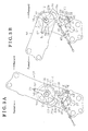
Fig. 3A is a side view of a seat apparatus in a case where the seat is in the occupied state according to the second embodiment; and -
Fig. 3B is a side view of the seat apparatus in a case where the seat is in the forward-inclined state according to the second embodiment. - A seat apparatus of first and second embodiments will be explained with reference to the drawings. Hereinafter, a front-rear direction of a seat is referred to as a front-rear direction. A width direction of the seat is referred to as a width direction. As shown in
Fig. 1A , a lower rail 2 extending in a front-rear direction is fixed to a floor 1 of a vehicle. Anupper rail 3 is relatively movably mounted to the lower rail 2 to be movable in the front-rear direction. The lower rail 2 is provided in a pair and is disposed away from each other in the width direction. Theupper rail 3 is provided in a pair and is disposed away from each other in the width direction. Each ofFigs. 1A and 1B shows the lower rail 2 and theupper rail 3 which are positioned on the left in a forward moving direction. Aseat 5 which corresponds to a seating portion of a passenger is fixed and supported by the upper rails 3. Theseat 5 includes aseat cushion 6 and aseatback 7. Theseat cushion 6 corresponds to a seat. Theseatback 7 is inclinedly or tiltedly supported relative to a rear end portion of theseat cushion 6. That is, the seat back 7 is supported relative to the rear end portion of theseat cushion 6 so as to pivot relative to the rear end portion. Accordingly, theseatback 7 is inclined forward and rearward relative to theseat cushion 6. - The
upper rail 3 supports a lock member 9 which selectively engages with the lower rail 2. The lock member 9 is biased by an appropriate biasing member to be engaged with the lower rail 2. Basically, the lock member 9 restricts the relative movement of the lower rail 2 and theupper rail 3, that is, the movement of theseat 5 in the front-rear direction. The lock member 9 is linked with theseatback 7 and is disengaged from the lower rail 2 against the biasing force of the biasing member in response to, for example, a forward inclination or a forward tilt or a leaned forward of theseatback 7. Accordingly, the lock member 9 allows the relative movement of the lower rail 2 and theupper rail 3, that is, the movement of theseat 5 in the front-rear direction. - The vehicle is provided with a retracting space S which is disposed at a rear of the lower rail 2. The retracting space S is provided to store the retracted
seat 5 which moves rearward along the lower rail 2 while theseatback 7 is in the forward-inclined state or the forward tilting state. - Next, the connection structure between the
seat cushion 6 and theseatback 7 will be explained. As shown inFig. 2A , theseat cushion 6 is fixed with alower arm 10 which is made from, for example, metal plate. Theseatback 7 is fixed with anupper arm 15 which is made from, for example, metal plate. An upper end portion of thelower arm 10 and a lower end portion of theupper arm 15 are disposed overlappingly with each other in the width direction. The overlapped portions of thelower arm 10 and theupper arm 15 are provided with aninternal gear 11 and anexternal gear 16, respectively. Theinternal gear 11 is formed in a bottomed, substantially cylindrical shape and is recessed in the width direction from a surface of thelower arm 10 which opposes theupper arm 15. Theexternal gear 16 is formed in a substantial columnar shape and protrudes toward thelower arm 10 in the width direction to be housed in theinternal gear 11. Theinternal gear 11 and theexternal gear 16 are meshed with each other eccentrically. Respective centers of theinternal gear 11 and theexternal gear 16 are referred to as a first center O1 and asecond center 02. Teeth of theexternal gear 16 are set to be fewer than teeth of theinternal gear 11. A known hypocycloid reduction gear is configured with theinternal gear 11, theexternal gear 16, a wedge member and a cam shaft. Because the wedge member holds theinternal gear 11 and theexternal gear 16 eccentrically, theinternal gear 11 and theexternal gear 16 mesh with each other. The cam shaft is disposed coaxially with theinternal gear 11 and axially supports theupper arm 15. The cam shaft moves the wedge member. - The cam shaft is connected to output shafts of an appropriate operation handle or an appropriate electric motor and integrally rotates with the operation handle or the electric motor in response to the rotation of the output shafts. By the movement of the wedge member in response to the rotation of the cam shaft, the
upper arm 15 revolves while the wedge member holds theinternal gear 11 and theexternal gear 16 to be meshed with each other to decrease the rotary speed of the cam shaft which corresponds to the rotation of theupper arm 15 during the revolving. In other words, theupper arm 15 rotates relative to thelower arm 10 in accordance with the difference of the respective numbers of the teeth ofinternal gear 11 and theexternal gear 16. Because theupper arm 15 rotates relative to thelower arm 10, theseatback 7 rotates (is inclined or tilted) relative to theseat cushion 6. - The
lower arm 10 is provided with a substantially-cylindrical bearing portion 12 which is disposed coaxially with the first center O1 and protrudes toward theupper arm 15 in the width direction. The bearingportion 12 is disposed in theupper arm 15 while including a play which accepts the eccentricity of theinternal gear 11 and theexternal gear 16. The bearingportion 12 is inserted with a first lever 21 (i.e., serving as a lever) which is positioned overlappingly with theupper arm 15 at an opposite side from a side where thelower arm 10 is overlappingly provided in the width direction. Thefirst lever 21 is made from, for example, metal plate, and is rotatably supported by thelower arm 10 via the bearingportion 12. Thefirst lever 21 is unmovably supported by thelower arm 10 in the axial direction via the bearingportion 12. - The
first lever 21 includes a substantiallylongitudinal connection piece 22 disposed along theupper arm 15 and extending upward shown inFig. 2A . A distal end of theconnection piece 22 protrudes outward relative to an end (upper end) of thelower arm 10. The distal end of theconnection piece 22 is provided with a substantiallyU-shaped engagement groove 22a (i.e., serving as a transmission portion, a recessed portion) recessed toward the first center O1. The recessed amount of theengagement groove 22a toward the first center O1 is set to be larger than an opening width of theengagement groove 22a in a circumferential direction relative to the first center O1. Specifically, the recessed amount of theengagement groove 22a toward the first center O1 is set to be equivalent to a distance which is twice the distance between the first center O1 and thesecond center 02. - The
upper arm 15 is provided with a substantially cylindrical protrusion 17 (i.e., serving as a transmission portion, a protrusion) which has a diameter equivalent to the opening width of theengagement groove 22a and protrudes in the width direction. Theprotrusion 17 is disposed in theengagement groove 22a and transmits the rotation of theupper arm 15 to thefirst lever 21 when theupper arm 15 rotates relative to thelower arm 10. Along with the movement of theupper arm 15, theprotrusion 17 moves in the radial direction relative to the first center O1 within the range of the recessed amount of theengagement groove 22a. Accordingly, in a case where theupper arm 15 is shifted radially from thelower arm 10 on a straight line which connects the first center O1 and theengagement groove 22a because theinternal gear 11 and theexternal gear 16 are eccentrically meshed with each other, theprotrusion 17 moves within theengagement groove 22a to absorb the eccentricity. Each of theprotrusion 17 and theengagement groove 22a serves as the transmission portion. - The
first lever 21 includes a substantially fan-shapedpressing piece 23 extending forward and downward shown inFig. 2A . An outer peripheral surface of thepressing piece 23 is provided outward relative to an end (lower end) of theupper arm 15. The outer peripheral surface of thepressing piece 23 extends in the circumferential direction relative to the first center O1 and includes a holdingsurface 23a (i.e., serving as a release portion). Apressing surface 23b is positioned at a side surface which corresponds to a surface of thepressing piece 23, the surface which precedes in the anti-clockwise direction relative to the first center O1. Thepressing surface 23b extends in the radial direction relative to the first center O1. - The
lower arm 10 is provided with abracket 25 which is made from, for example, metal plate. Thebracket 25 is fixed to thelower arm 10 below theupper arm 15 and is overlappingly fixed at a side where thefirst lever 21 is disposed in the width direction. A substantiallycolumnar support pin 26 protrudes from thebracket 25 in the width direction. Accordingly, asecond lever 30 and acable lever 40 are rotatably supported in the sequentially-overlapped manner in the width direction from the side where thefirst lever 21 is disposed. - The
second lever 30 is made from, for example, metal plate and includes a firstlever protruding piece 31 and a secondlever protruding piece 32 serving as a pair and extending upward and rearward in the radial direction, respectively, relative to thesupport pin 26 to be formed in a substantially L shape. A distal end of the firstlever protruding piece 31 is provided with a substantiallycolumnar engagement pin 33 which protrudes in the width direction. The firstlever protruding piece 31 is positioned closer to thelower arm 10 than thepressing piece 23 in the width direction. The firstlever protruding piece 31 is positioned off a rotation trajectory of thepressing piece 23 in the anti-clockwise direction relative to the first center O1 in accordance with the forward inclination of theseatback 7, that is, the rotation of theupper arm 15 in the anti-clockwise direction. Theengagement pin 33 is disposed on the rotation trajectory of thepressing piece 23 in the anti-clockwise direction relative to the first center O1 in accordance with the forward inclination of theseatback 7. Thus, because thepressing piece 23 rotates in the anti-clockwise direction in accordance with the forward inclination of theseatback 7, theengagement pin 33 is pressed by thepressing piece 23 to rotate thesecond lever 30 in the clockwise direction. A distal end of the secondlever protruding piece 32 is provided with a substantially columnarpressing pin 34 which protrudes in the width direction. - The
cable lever 40 is made from, for example, metal plate and includes a thirdlever protruding piece 41 and a fourthlever protruding piece 42 serving as a pair and extending rearward and forward in the radial direction, respectively, relative to thesupport pin 26. A distal end of the thirdlever protruding piece 41 is provided with alongitudinal hole 43 which extends in a circumferential direction relative to thesupport pin 26 and which opens in the width direction. Thepressing pin 34 of thesecond lever 30 is disposed in thelongitudinal hole 43. Thus, thecable lever 40 rotates in the clockwise direction relative to thesupport pin 26 because thepressing pin 34 presses an inner wall surface of thelongitudinal hole 43 in accordance with the rotation of thesecond lever 30 in the clockwise direction. - A distal end of the fourth
lever protruding piece 42 is connected to a first terminal of acable 45 which extends from thebracket 25. A second terminal of thecable 45 is connected to the lock member 9. Because thecable 45 is pulled by the fourthlever protruding piece 42 in accordance with the rotation of thecable lever 40 in the clockwise direction, the lock member 9 is operated to allow the movement of theseat 5 in the front-rear direction. - The
cable lever 40 is constantly biased by an appropriate biasing member in the anticlockwise direction. Thebracket 25 is provided with astopper piece 27 which protrudes in the width direction to be disposed on the rotation trajectory of the fourth protrudingpiece 42 in the anti-clockwise direction. Thus, thecable lever 40 is normally held at a predetermined rotary position (hereinafter referred to as an initial position) where the fourthlever protruding piece 42 is in contact with thestopper piece 27 by the biasing force of the biasing member. At this time, because thecable 45 is not pulled by the fourthlever protruding piece 42, the lock member 9 restricts the movement of theseat 5 in the front-rear direction. - The
second lever 30 is constantly biased by an appropriate biasing member in the clockwise direction with a biasing force smaller than the biasing force applied to thecable lever 40. Thus, thesecond lever 30 is normally held at a predetermined rotational position (hereinafter referred to as an initial position) where thepressing pin 34 presses the inner wall surface of thelongitudinal hole 43, the inner wall surface that precedes in the clockwise direction by the biasing force of the biasing member. At this time, because thesecond lever 30 is positioned away from thestopper piece 27, thesecond lever 30 does not interfere with thestopper piece 27. - Next, effects and advantages attained by the first embodiment will be explained. As shown in
Fig. 2A , theseatback 7 is in an occupied state and thepressing piece 23 of thefirst lever 21 is disposed away from theengagement pin 33 of thesecond lever 30. At this time, thesecond lever 30 and thecable lever 40 are held at the respective initial positions. The lock member 9 restricts the movement of theseat 5 in the front-rear direction. Theupper arm 15 is shifted radially away from thelower arm 10 on the straight line which connects the first center O1 and theengagement groove 22a. That is, theexternal gear 16 of theupper arm 15 meshes with theinternal gear 11 in a state where thesecond center 02 of theexternal gear 16 of theupper arm 15 is shifted radially away from thelower arm 10 on the straight line which connects the first center O1 and theengagement groove 22a. - In such a state, when the cam shaft rotates to have the
seatback 7 inclined forward, theseatback 7 rotates (is inclined forward) relative to theseat cushion 6 in response to the rotation of theupper arm 15 relative to thelower arm 10. Then, because theprotrusion 17 presses the inner wall surface of theengagement groove 22a, thefirst lever 21 rotates in the anti-clockwise direction relative to the first center O1. Along with that, because thepressing surface 23b of thepressing piece 23 reaches theengagement pin 33 of thesecond lever 30 and pushes theengagement pin 33, thesecond lever 30 rotates in the clockwise direction relative to thesupport pin 26. Because thepressing pin 34 presses the inner wall surface of thelongitudinal hole 43, thecable lever 40 rotates in the clockwise direction relative to thesupport pin 26. Along with that, the fourthlever protruding piece 42 pulls thecable 45 to operate the lock member 9 to allow the movement of theseat 5 in the front-rear direction. - When the
seatback 7 is inclined forward, thepressing surface 23b of thepressing piece 23 presses theengagement pin 33 so that theengagement pin 33 slides in an outer circumferential direction. That is, theengagement pin 33 rotates in the clockwise direction in response to the rotation of thefirst lever 21 in the anti-clockwise direction. The lock member 9 which is connected to thecable 45 is set to allow the movement of theseat 5 in the front-rear direction no later than the time when an outer circumferential end of thepressing surface 23b, or an outer end of thepressure surface 23b in the radial direction reaches theengagement pin 33. In a case where theengagement pin 33 slides on thepressing surface 23b and reaches the holdingsurface 23a when theseatback 7 is further inclined forward, theengagement pin 33 slides on the holdingsurface 23a in the circumferential direction and is held thereby. Accordingly, thesecond lever 30 is held at the rotational position and the lock member 9 holds theseat 5 to be in the allowed state of the movement of theseat 5 in the front-rear direction. - As shown in
Fig. 2B , when theengagement pin 33 reaches an end of the holdingsurface 23a in response to the further forward inclination of theseatback 7, the forward inclination of theseatback 7 is completed. At this time, the lock member 9 still holds the allowed state of the movement of theseat 5 in the front-rear direction. Further, theupper arm 15 is shifted radially closer to thelower arm 10 on the straight line which connects the first center O1 and theengagement groove 22a. That is, theexternal gear 16 of theupper arm 15 meshes with theinternal gear 11 in a state where thesecond center 02 of theexternal gear 16 is shifted closer to thelower arm 10 on the straight line which connects the first center O1 and theengagement groove 22a. - As shown in
Figs. 2A and 2B which illustrate before and after the change of the posture of theseatback 7 by the forward inclination, respectively, theprotrusion 17 inFig. 2A is disposed at a different position from theprotrusion 17 inFig. 2B within theengagement groove 22a. However, inFigs. 2A and 2B , thesecond center 02 of theexternal gear 16 is disposed on the straight line which connects the first center O1 and theengagement groove 22a. The rotational position (inclination angle) of theupper arm 15 relative to thelower arm 10 corresponds to the rotational position (inclination angle) of thefirst lever 21 relative to thelower arm 10. - As above, when the
upper arm 15 revolves while theinternal gear 11 and theexternal gear 16 are held in the meshed state, the eccentricity of theinternal gear 11 and theexternal gear 16 is absorbed by a space or a clearance between theprotrusion 17 and theengagement groove 22a and the rotation of theupper arm 15 is transmitted to thefirst lever 21 as long as thesecond center 02 is disposed on the straight line which connects the first center O1 and theengagement groove 22a. Even if thesecond center 02 is not disposed on the straight line which connects the first center O1 and theengagement groove 22a, the eccentricity of theinternal gear 11 and theexternal gear 16 is absorbed at least by a distance between the first center O1 and thesecond center 02 in the straight line direction by an application of the space or the clearance between theprotrusion 17 and theengagement groove 22a. Accordingly, the rotation of theupper arm 15 is securely transmitted to thefirst lever 21. - As described above, the
first lever 21 is rotatably connected to thelower arm 10 fixed to theseat cushion 6 and is linked with the lock member 9 which is supported at theseat cushion 6. Thus, despite the eccentricity of the upper arm 15 (the external gear 16) relative to the lower arm 10 (the internal gear 11), thecable 45 is further stably pulled by the fourthlever protruding piece 42 in accordance with, for example, the rotation of thefirst lever 21. Accordingly, the lock member 9 further stably allows the movement of theseat 5. - As shown in
Fig. 2B . when theupper arm 15 is rotated to have theseatback 7 further inclined forward in a state where the forward inclination of theseatback 7 is completed, the holdingsurface 23a of thefirst lever 21 which rotates in accordance with the rotation of theupper arm 15 passes through theengagement pin 33 of thesecond lever 30 to release thesecond lever 30. At this time, each of thesecond lever 30 and thecable lever 40 returns to the initial position by being biased by the corresponding biasing member. Then, the lock member 9 restricts the movement of theseat 5 in the front-rear direction. The end of the holdingsurface 23a or the end of the holdingsurface 23a in the preceding direction configures a release portion. - That is, as shown in
Fig. 1B , in a state where the forward inclination of theseatback 7 is completed, theseat 5 which is in the allowed state of the movement in the front-rear direction moves rearward to be stored in the retracting space S. Then, the movement of theseat 5 is restricted to fix theseat 5 which is stored in the retracting space S. The biasing power of the appropriate biasing member can be applied to move theseat 5 which is in the allowed state of the movement in the front-rear direction rearward. Alternatively, theseat 5 can be pulled with, for example, a rope by an application of the change of the posture of theseat 5 in accordance with the forward inclination of theseatback 7. Alternatively, theseat 5 can be pulled manually. - As described above, according to the first embodiment, following effects and advantages may be attained.
- According to the aforementioned first embodiment, the rotation of the
upper arm 15 corresponding to, or in accordance with the forward inclination of theseatback 7 is transmitted to thefirst lever 21 while the eccentricity of theinternal gear 11 and theexternal gear 16 is absorbed by theengagement groove 22a and theprotrusion 17. Then, the lock member 9 which is linked with thefirst lever 21 is operated to allow the movement of theseat 5. As such, the lock member 9 which is supported at theseat cushion 6 further securely allows the movement of theseat 5 because the lock member 9 is linked with thefirst lever 21 which is disposed coaxially with theinternal gear 11 of thelower arm 10 being fixed to theseat cushion 6 and is rotatably linked with thelower arm 10. - According to the aforementioned first embodiment, the
first lever 21 rotates in response to the rotation of theupper arm 15 which corresponds to, or in accordance with the forward inclination of theseatback 7. Accordingly, the lock member 9 is operated to allow the movement of theseat 5 in response to the rotation of thesecond lever 30. When the holdingsurface 23a of thefirst lever 21 passes through theengagement pin 33 of thesecond lever 30, that is, when the rotary amount of thefirst lever 21 exceeds a predetermined amount, thesecond lever 30 is released from the first lever 21 (the holdingsurface 23a). Thus, the lock member 9 is operated to restrict the movement of theseat 5. - According to the aforementioned first embodiment, the
protrusion 17 and theengagement groove 22a are easily configured to absorb the eccentricity of theinternal gear 11 and theexternal gear 16. The aforementioned first embodiment can be modified as follows. - The positional relationship of the
upper arm 15 and thefirst lever 21 can be replaced with each other. The positional relationship of theprotrusion 17 and theengagement groove 22a can be replaced with each other. That is, as shown inFigs. 3A and 3B , anupper arm 50 of the second embodiment, which corresponds to theupper arm 15 in the first embodiment, includes a substantially longitudinal engagement hole 51 (i.e., serving as a transmission portion, a recessed portion). Theengagement hole 51 extends in the radial direction relative to thesecond center 02 and penetrates theupper arm 50 in the width direction. Theengagement hole 51 is disposed outward relative to the end (upper end) of thelower arm 10. Alternatively, theengagement hole 51 may be a recessed portion recessed in the width direction without penetrating theupper arm 50. - A
connection piece 56 of a first lever 55 (i.e., serving as a lever) of the second embodiment, which corresponds to theconnection piece 22 of thefirst lever 21 in the first embodiment, includes a distal end which is provided with a substantially pawl-shaped protrusion 57 (i.e., serving as a transmission portion, a protrusion). Theprotrusion 57 protrudes in the width direction toward theupper arm 50 and is inserted into and positioned in theengagement hole 51. Accordingly, when theupper arm 50 rotates relative to thelower arm 10, the rotation of theupper arm 50 is transmitted to thefirst lever 55 via theprotrusion 57. Theprotrusion 57 moves in the radial direction relative to thesecond center 02 within the range of the opening width of theengagement hole 51 in the extending direction (the radial direction). - Thus, in a case where the
lower arm 10 is shifted radially from theupper arm 50 on a straight line which connects thesecond center 02 and theengagement hole 51 because theinternal gear 11 and theexternal gear 16 eccentrically mesh with each other, theprotrusion 57 moves in theengagement hole 51 to absorb the eccentricity of theinternal gear 11 and theexternal gear 16. Each of theengagement hole 51 and theprotrusion 57 serves as the transmission portion. - As shown in
Fig. 3A , thelower arm 10 is shifted radially away from theupper arm 50 on the straight line which connects thesecond center 02 and theengagement hole 51 when theseatback 7 is in the occupied state. That is, theinternal gear 11 of thelower arm 10 meshes with theexternal gear 16 of theupper arm 50 in a state where the first center O1 of theinternal gear 11 of thelower arm 10 is shifted away from theupper arm 50 on the straight line which connects thesecond center 02 and theengagement hole 51. As shown inFig. 3B , in a case where the forward inclination of theseatback 7 is completed, thelower arm 10 is shifted radially closer to thelower arm 10 on the straight line which connects thesecond center 02 and theengagement hole 51. That is, theinternal gear 11 of thelower arm 10 meshes with theexternal gear 16 of theupper arm 50 in a state where the first center O1 of theinternal gear 11 of thelower arm 10 is shifted closer to theupper arm 50 on the straight line which connects thesecond center 02 and theengagement hole 51. - Thus, before and after the forward inclination of the
seatback 7, theprotrusion 57 inFig. 3A is disposed at a different position from theprotrusion 57 inFig. 3B within theengagement hole 51. However, inFigs. 3A and 3B , the first center O1 of theinternal gear 11 is disposed on the straight line which connects thesecond center 02 and theengagement hole 51. The rotational position (the inclination angle) of theupper arm 50 relative to thelower arm 10 corresponds to the rotational position (the inclination angle) of thefirst lever 55 relative to thelower arm 10. As above, the second embodiment can obtain the similar effects and advantages as those obtained in the first embodiment. - According to the first and second embodiments, the
first lever second lever 30 does not have to be provided. - According to the first and second embodiments, the positional relationship of the
lower arm 10 and theupper arm internal gear 11 and theexternal gear 16 are replaced with each other. - According to the first and second embodiments, the lower arm 10 (or the
upper arm 15, 50) is provided with a separate internal gear. Theupper arm 15, 50 (or the lower arm 10) is provided with a separate external gear. - According to the first and second embodiments, the
seatback 7 is inclined forward to store theseat 5 in the retracting space S. Alternatively, for example, theseatback 7 is inclined forward to be disposed on theseat cushion 6 to be used as a table.
Claims (3)
- A seat apparatus, comprising:a seat (5);a seat cushion (6) of the seat (5);a seatback (7) of the seat (5);a lower arm (10) being fixed to the seat cushion (6), the lower arm (10) including one of an internal gear (11) and an external gear (16) which includes teeth fewer than teeth of the internal gear (11), the external gear (16) eccentrically meshing with the internal gear (11);an upper arm (15, 50) being fixed to the seatback (7), the upper arm (15, 50) including the other of the internal gear (11) and the external gear (16);a lock member (9) being supported at the seat cushion (6), the lock member (9) being configured to restrict and allow a movement of the seat (5);a lever (21, 55) being coaxially disposed with one of the internal gear (11) and the external gear (16) provided at the lower arm (10), the lever (21, 55) being rotatably connected to the lower arm (10), the lever (21, 55) being linked with an operation of the lock member (9) to restrict the movement; anda transmission portion (17, 22a, 51, 57) disposed between the lower arm (10) and the upper arm (15, 50), the transmission portion (17, 22a, 51, 57) being configured to transmit a rotation of the upper arm (15, 50) which corresponds to a forward inclination of the seatback (7) to the lever (21, 55) by absorbing an eccentricity of the internal gear (11) and the external gear (16).
- The seat apparatus according to claim 1, wherein the lever (21, 55) serves as a first lever (21, 55);
the seat apparatus further comprising:a second lever (30) being rotatably connected to the lower arm (10), the second lever (30) disposed on a rotation trajectory of a rotation of the first lever (21, 55), the rotation corresponding to the forward inclination of the seatback (7); anda release portion (23a) being disposed between the first lever (21, 55) and the second lever (30); whereinthe first lever (21, 55) is configured to rotate the second lever (30) in accordance with the rotation of the first lever (21, 55) to operate the lock member (9) to allow the movement; andthe release portion (23a) is configured to release the second lever (30) from the rotation of the first lever (21, 55) in a case where a rotary amount of the rotation of the first lever (21, 55), the rotation corresponding to the forward inclination of the seatback (7) exceeds a predetermined amount. - The seat apparatus according to either claim 1 or 2; wherein the transmission portion (17, 22a, 51, 57) includes;
a protrusion (17, 57) protruding from one of the upper arm (15, 50) and the lever (55); and
a recessed portion (22a, 51) being provided at the other of the upper arm (15, 50) and the lever (21, 55), the recessed portion (22a, 51) being inserted with the protrusion (17, 57), the protrusion (17, 57) which is movable, to absorb the eccentricity of the internal gear (11) and the external gear (16).
Applications Claiming Priority (1)
| Application Number | Priority Date | Filing Date | Title |
|---|---|---|---|
| JP2014061834A JP6295763B2 (en) | 2014-03-25 | 2014-03-25 | Sheet device |
Publications (1)
| Publication Number | Publication Date |
|---|---|
| EP2923885A1 true EP2923885A1 (en) | 2015-09-30 |
Family
ID=52686247
Family Applications (1)
| Application Number | Title | Priority Date | Filing Date |
|---|---|---|---|
| EP15159876.0A Withdrawn EP2923885A1 (en) | 2014-03-25 | 2015-03-19 | Seat apparatus |
Country Status (4)
| Country | Link |
|---|---|
| US (1) | US9586502B2 (en) |
| EP (1) | EP2923885A1 (en) |
| JP (1) | JP6295763B2 (en) |
| CN (1) | CN204712903U (en) |
Families Citing this family (6)
| Publication number | Priority date | Publication date | Assignee | Title |
|---|---|---|---|---|
| JP6237465B2 (en) * | 2014-05-23 | 2017-11-29 | トヨタ紡織株式会社 | Vehicle seat |
| DE102015218873B4 (en) * | 2015-07-20 | 2018-04-26 | Adient Luxembourg Holding S.À R.L. | vehicle seat |
| US9902296B2 (en) * | 2016-05-25 | 2018-02-27 | Lear Corporation | Seatback drive system spring down, power up |
| CN105946632B (en) * | 2016-06-15 | 2018-01-26 | 合肥云鹤安道拓汽车座椅有限公司 | A kind of convenient unlocking mechanism of taking a seat |
| US10464453B2 (en) * | 2017-09-19 | 2019-11-05 | Kiekert Ag | Motor vehicle seat, in particular a motor vehicle rear seat |
| CN109435793A (en) * | 2018-09-29 | 2019-03-08 | 延锋安道拓座椅有限公司 | A kind of unlocking mechanism convenient for rear passenger disengaging |
Citations (4)
| Publication number | Priority date | Publication date | Assignee | Title |
|---|---|---|---|---|
| DE10012009A1 (en) * | 2000-03-11 | 2001-09-20 | Faurecia Autositze Gmbh & Co | Angle setting fitting with free slue device for vehicle seat free slue bearing formed by boring of free slue device and through aperture in angle setting fitting component |
| JP2003182415A (en) | 2001-12-25 | 2003-07-03 | Aisin Seiki Co Ltd | Seat device |
| WO2007087876A1 (en) * | 2006-01-24 | 2007-08-09 | Keiper Gmbh & Co. Kg | Fitting for a vehicle seat |
| JP2009062241A (en) | 2007-09-07 | 2009-03-26 | Hokkaido Univ | Graphene sheet manufacturing method |
Family Cites Families (8)
| Publication number | Priority date | Publication date | Assignee | Title |
|---|---|---|---|---|
| JPH0546690Y2 (en) * | 1988-08-31 | 1993-12-07 | ||
| JPH0289946U (en) * | 1988-12-28 | 1990-07-17 | ||
| CA2316259C (en) * | 1998-01-28 | 2003-07-08 | Bertrand Faure Components Ltd. | Rotary recliner control mechanism for multifunction vehicle seat applications |
| JP2004058928A (en) * | 2002-07-31 | 2004-02-26 | Fuji Kiko Co Ltd | Vehicle seat folding mechanism |
| DE10315375A1 (en) * | 2003-04-03 | 2004-11-11 | Keiper Gmbh & Co. Kg | Fitting system for a vehicle seat |
| JP4302756B2 (en) * | 2007-06-29 | 2009-07-29 | トヨタ紡織株式会社 | Vehicle seat |
| JP5076780B2 (en) | 2007-09-27 | 2012-11-21 | アイシン精機株式会社 | Vehicle seat reclining device |
| JP5880312B2 (en) * | 2012-06-26 | 2016-03-09 | トヨタ紡織株式会社 | Vehicle seat |
-
2014
- 2014-03-25 JP JP2014061834A patent/JP6295763B2/en not_active Expired - Fee Related
-
2015
- 2015-02-24 US US14/630,154 patent/US9586502B2/en not_active Expired - Fee Related
- 2015-03-19 EP EP15159876.0A patent/EP2923885A1/en not_active Withdrawn
- 2015-03-19 CN CN201520157438.0U patent/CN204712903U/en not_active Expired - Fee Related
Patent Citations (4)
| Publication number | Priority date | Publication date | Assignee | Title |
|---|---|---|---|---|
| DE10012009A1 (en) * | 2000-03-11 | 2001-09-20 | Faurecia Autositze Gmbh & Co | Angle setting fitting with free slue device for vehicle seat free slue bearing formed by boring of free slue device and through aperture in angle setting fitting component |
| JP2003182415A (en) | 2001-12-25 | 2003-07-03 | Aisin Seiki Co Ltd | Seat device |
| WO2007087876A1 (en) * | 2006-01-24 | 2007-08-09 | Keiper Gmbh & Co. Kg | Fitting for a vehicle seat |
| JP2009062241A (en) | 2007-09-07 | 2009-03-26 | Hokkaido Univ | Graphene sheet manufacturing method |
Also Published As
| Publication number | Publication date |
|---|---|
| JP2015182645A (en) | 2015-10-22 |
| US9586502B2 (en) | 2017-03-07 |
| CN204712903U (en) | 2015-10-21 |
| JP6295763B2 (en) | 2018-03-20 |
| US20150274037A1 (en) | 2015-10-01 |
Similar Documents
| Publication | Publication Date | Title |
|---|---|---|
| US9586502B2 (en) | Seat apparatus | |
| KR100840404B1 (en) | Hinge mechanism for vehicle seat and seat with hinge mechanism | |
| US6715835B2 (en) | Seat reclining apparatus | |
| JP6196185B2 (en) | Vehicle seat and manufacturing method thereof | |
| US7992938B2 (en) | Seat reclining apparatus for vehicle | |
| JP6232983B2 (en) | Deceleration device and seat drive device | |
| US20200215935A1 (en) | Vehicle seat device | |
| KR100380572B1 (en) | Backlash reducing structure for recliner adjuster | |
| JP4653523B2 (en) | Vehicle seat reclining device | |
| JP2006204506A (en) | Reclining adjuster | |
| CN101638064A (en) | Seat reclining apparatus for vehicle | |
| CN102811883A (en) | Adjusting Apparatus | |
| EP1764258A2 (en) | Seat reclining apparatus | |
| JP6588025B2 (en) | Rotation motion control mechanism and seat | |
| US9176518B2 (en) | Handle returning apparatus and seat lifting apparatus for vehicle | |
| KR20110054714A (en) | Dial Type Seat Heightening Device | |
| JP4968326B2 (en) | Vehicle seat reclining device | |
| JP2008154992A (en) | Vehicle seat reclining device | |
| CN113795405A (en) | An adjustment accessory for a vehicle seat and a vehicle seat | |
| JP5781890B2 (en) | Reduction gear mechanism | |
| JP2002291563A (en) | Vehicle seat reclining device | |
| KR101432223B1 (en) | Vehicle seat with a memory device | |
| JP6647787B2 (en) | Clutch unit | |
| JP2019014422A (en) | Reclining device | |
| JP2007330443A (en) | Vehicle seat reclining device |
Legal Events
| Date | Code | Title | Description |
|---|---|---|---|
| PUAI | Public reference made under article 153(3) epc to a published international application that has entered the european phase |
Free format text: ORIGINAL CODE: 0009012 |
|
| AK | Designated contracting states |
Kind code of ref document: A1 Designated state(s): AL AT BE BG CH CY CZ DE DK EE ES FI FR GB GR HR HU IE IS IT LI LT LU LV MC MK MT NL NO PL PT RO RS SE SI SK SM TR |
|
| AX | Request for extension of the european patent |
Extension state: BA ME |
|
| 17P | Request for examination filed |
Effective date: 20160329 |
|
| RBV | Designated contracting states (corrected) |
Designated state(s): AL AT BE BG CH CY CZ DE DK EE ES FI FR GB GR HR HU IE IS IT LI LT LU LV MC MK MT NL NO PL PT RO RS SE SI SK SM TR |
|
| RIC1 | Information provided on ipc code assigned before grant |
Ipc: B60N 2/20 20060101ALI20180924BHEP Ipc: B60N 2/225 20060101AFI20180924BHEP |
|
| GRAP | Despatch of communication of intention to grant a patent |
Free format text: ORIGINAL CODE: EPIDOSNIGR1 |
|
| INTG | Intention to grant announced |
Effective date: 20181114 |
|
| STAA | Information on the status of an ep patent application or granted ep patent |
Free format text: STATUS: THE APPLICATION IS DEEMED TO BE WITHDRAWN |
|
| 18D | Application deemed to be withdrawn |
Effective date: 20190326 |