EP2923657A1 - Modular powered surgical instrument with detachable shaft assemblies - Google Patents
Modular powered surgical instrument with detachable shaft assemblies Download PDFInfo
- Publication number
- EP2923657A1 EP2923657A1 EP15161151.4A EP15161151A EP2923657A1 EP 2923657 A1 EP2923657 A1 EP 2923657A1 EP 15161151 A EP15161151 A EP 15161151A EP 2923657 A1 EP2923657 A1 EP 2923657A1
- Authority
- EP
- European Patent Office
- Prior art keywords
- assembly
- housing
- surgical instrument
- shaft assembly
- closure
- Prior art date
- Legal status (The legal status is an assumption and is not a legal conclusion. Google has not performed a legal analysis and makes no representation as to the accuracy of the status listed.)
- Granted
Links
- 230000000712 assembly Effects 0.000 title description 38
- 238000000429 assembly Methods 0.000 title description 38
- 238000010304 firing Methods 0.000 claims description 155
- 239000012636 effector Substances 0.000 claims description 128
- 238000005520 cutting process Methods 0.000 claims description 52
- 230000033001 locomotion Effects 0.000 claims description 48
- 238000010168 coupling process Methods 0.000 claims description 25
- 230000008878 coupling Effects 0.000 claims description 24
- 238000005859 coupling reaction Methods 0.000 claims description 24
- 230000004044 response Effects 0.000 claims description 17
- 238000009434 installation Methods 0.000 claims description 3
- 238000004891 communication Methods 0.000 description 71
- 230000015654 memory Effects 0.000 description 68
- 210000001519 tissue Anatomy 0.000 description 54
- 238000000034 method Methods 0.000 description 40
- 230000001954 sterilising effect Effects 0.000 description 39
- 238000004659 sterilization and disinfection Methods 0.000 description 39
- 230000007246 mechanism Effects 0.000 description 32
- 230000005355 Hall effect Effects 0.000 description 25
- 238000012544 monitoring process Methods 0.000 description 16
- 239000012530 fluid Substances 0.000 description 15
- 230000005540 biological transmission Effects 0.000 description 13
- 238000010586 diagram Methods 0.000 description 13
- 230000006870 function Effects 0.000 description 13
- 238000006073 displacement reaction Methods 0.000 description 12
- 239000003990 capacitor Substances 0.000 description 11
- 239000004020 conductor Substances 0.000 description 10
- 230000037361 pathway Effects 0.000 description 10
- 239000000463 material Substances 0.000 description 9
- 238000003860 storage Methods 0.000 description 9
- 230000009471 action Effects 0.000 description 8
- 238000004519 manufacturing process Methods 0.000 description 8
- 238000001356 surgical procedure Methods 0.000 description 8
- 230000000007 visual effect Effects 0.000 description 8
- 230000006835 compression Effects 0.000 description 7
- 238000007906 compression Methods 0.000 description 7
- 238000012545 processing Methods 0.000 description 7
- 239000000126 substance Substances 0.000 description 7
- 239000000758 substrate Substances 0.000 description 7
- 238000004140 cleaning Methods 0.000 description 6
- 230000013011 mating Effects 0.000 description 6
- 230000002829 reductive effect Effects 0.000 description 6
- 230000001133 acceleration Effects 0.000 description 5
- 230000008901 benefit Effects 0.000 description 5
- 230000008859 change Effects 0.000 description 5
- 239000003638 chemical reducing agent Substances 0.000 description 5
- PCHJSUWPFVWCPO-UHFFFAOYSA-N gold Chemical compound [Au] PCHJSUWPFVWCPO-UHFFFAOYSA-N 0.000 description 5
- 229910052737 gold Inorganic materials 0.000 description 5
- 239000010931 gold Substances 0.000 description 5
- 238000012986 modification Methods 0.000 description 5
- 230000004048 modification Effects 0.000 description 5
- 230000001953 sensory effect Effects 0.000 description 5
- RYGMFSIKBFXOCR-UHFFFAOYSA-N Copper Chemical group [Cu] RYGMFSIKBFXOCR-UHFFFAOYSA-N 0.000 description 4
- 238000010276 construction Methods 0.000 description 4
- 229910001416 lithium ion Inorganic materials 0.000 description 4
- 230000036961 partial effect Effects 0.000 description 4
- 230000008569 process Effects 0.000 description 4
- 230000005855 radiation Effects 0.000 description 4
- 230000002441 reversible effect Effects 0.000 description 4
- 238000012414 sterilization procedure Methods 0.000 description 4
- 230000001360 synchronised effect Effects 0.000 description 4
- HBBGRARXTFLTSG-UHFFFAOYSA-N Lithium ion Chemical compound [Li+] HBBGRARXTFLTSG-UHFFFAOYSA-N 0.000 description 3
- 238000001514 detection method Methods 0.000 description 3
- 230000005669 field effect Effects 0.000 description 3
- 230000002439 hemostatic effect Effects 0.000 description 3
- 230000000670 limiting effect Effects 0.000 description 3
- 238000007747 plating Methods 0.000 description 3
- 239000000853 adhesive Substances 0.000 description 2
- 230000001070 adhesive effect Effects 0.000 description 2
- 230000015572 biosynthetic process Effects 0.000 description 2
- 238000004590 computer program Methods 0.000 description 2
- 230000007797 corrosion Effects 0.000 description 2
- 238000005260 corrosion Methods 0.000 description 2
- 230000009849 deactivation Effects 0.000 description 2
- 239000003814 drug Substances 0.000 description 2
- 229940079593 drug Drugs 0.000 description 2
- 238000002651 drug therapy Methods 0.000 description 2
- 230000000694 effects Effects 0.000 description 2
- 238000001415 gene therapy Methods 0.000 description 2
- 238000003780 insertion Methods 0.000 description 2
- 230000037431 insertion Effects 0.000 description 2
- 230000036244 malformation Effects 0.000 description 2
- 230000005055 memory storage Effects 0.000 description 2
- 230000002093 peripheral effect Effects 0.000 description 2
- 230000000717 retained effect Effects 0.000 description 2
- 238000007789 sealing Methods 0.000 description 2
- 239000004065 semiconductor Substances 0.000 description 2
- 238000013519 translation Methods 0.000 description 2
- 230000001960 triggered effect Effects 0.000 description 2
- 238000002604 ultrasonography Methods 0.000 description 2
- 241000894006 Bacteria Species 0.000 description 1
- 241000238366 Cephalopoda Species 0.000 description 1
- IAYPIBMASNFSPL-UHFFFAOYSA-N Ethylene oxide Chemical compound C1CO1 IAYPIBMASNFSPL-UHFFFAOYSA-N 0.000 description 1
- 235000014676 Phragmites communis Nutrition 0.000 description 1
- 238000013459 approach Methods 0.000 description 1
- 238000003491 array Methods 0.000 description 1
- 238000005452 bending Methods 0.000 description 1
- 230000009286 beneficial effect Effects 0.000 description 1
- 210000000988 bone and bone Anatomy 0.000 description 1
- 230000015556 catabolic process Effects 0.000 description 1
- 239000002131 composite material Substances 0.000 description 1
- 230000007423 decrease Effects 0.000 description 1
- 238000006731 degradation reaction Methods 0.000 description 1
- 230000000994 depressogenic effect Effects 0.000 description 1
- 238000013461 design Methods 0.000 description 1
- 238000005516 engineering process Methods 0.000 description 1
- 230000007613 environmental effect Effects 0.000 description 1
- 239000002360 explosive Substances 0.000 description 1
- 239000000835 fiber Substances 0.000 description 1
- 239000003779 heat-resistant material Substances 0.000 description 1
- 238000007654 immersion Methods 0.000 description 1
- 238000012423 maintenance Methods 0.000 description 1
- 230000007257 malfunction Effects 0.000 description 1
- 239000000203 mixture Substances 0.000 description 1
- 239000003607 modifier Substances 0.000 description 1
- 239000012811 non-conductive material Substances 0.000 description 1
- 230000003287 optical effect Effects 0.000 description 1
- 230000002085 persistent effect Effects 0.000 description 1
- 238000002360 preparation method Methods 0.000 description 1
- 238000003825 pressing Methods 0.000 description 1
- 210000004872 soft tissue Anatomy 0.000 description 1
- 239000007787 solid Substances 0.000 description 1
- 230000000153 supplemental effect Effects 0.000 description 1
- 230000002123 temporal effect Effects 0.000 description 1
- 238000004804 winding Methods 0.000 description 1
- 230000003245 working effect Effects 0.000 description 1
Images


Classifications
-
- A—HUMAN NECESSITIES
- A61—MEDICAL OR VETERINARY SCIENCE; HYGIENE
- A61B—DIAGNOSIS; SURGERY; IDENTIFICATION
- A61B17/00—Surgical instruments, devices or methods, e.g. tourniquets
- A61B17/068—Surgical staplers, e.g. containing multiple staples or clamps
- A61B17/072—Surgical staplers, e.g. containing multiple staples or clamps for applying a row of staples in a single action, e.g. the staples being applied simultaneously
- A61B17/07207—Surgical staplers, e.g. containing multiple staples or clamps for applying a row of staples in a single action, e.g. the staples being applied simultaneously the staples being applied sequentially
-
- A—HUMAN NECESSITIES
- A61—MEDICAL OR VETERINARY SCIENCE; HYGIENE
- A61B—DIAGNOSIS; SURGERY; IDENTIFICATION
- A61B17/00—Surgical instruments, devices or methods, e.g. tourniquets
- A61B17/068—Surgical staplers, e.g. containing multiple staples or clamps
- A61B17/0682—Surgical staplers, e.g. containing multiple staples or clamps for applying U-shaped staples or clamps, e.g. without a forming anvil
- A61B17/0686—Surgical staplers, e.g. containing multiple staples or clamps for applying U-shaped staples or clamps, e.g. without a forming anvil having a forming anvil staying below the tissue during stapling
-
- A—HUMAN NECESSITIES
- A61—MEDICAL OR VETERINARY SCIENCE; HYGIENE
- A61B—DIAGNOSIS; SURGERY; IDENTIFICATION
- A61B17/00—Surgical instruments, devices or methods, e.g. tourniquets
- A61B17/32—Surgical cutting instruments
- A61B17/320016—Endoscopic cutting instruments, e.g. arthroscopes, resectoscopes
-
- A—HUMAN NECESSITIES
- A61—MEDICAL OR VETERINARY SCIENCE; HYGIENE
- A61B—DIAGNOSIS; SURGERY; IDENTIFICATION
- A61B90/00—Instruments, implements or accessories specially adapted for surgery or diagnosis and not covered by any of the groups A61B1/00 - A61B50/00, e.g. for luxation treatment or for protecting wound edges
- A61B90/90—Identification means for patients or instruments, e.g. tags
- A61B90/98—Identification means for patients or instruments, e.g. tags using electromagnetic means, e.g. transponders
-
- A—HUMAN NECESSITIES
- A61—MEDICAL OR VETERINARY SCIENCE; HYGIENE
- A61L—METHODS OR APPARATUS FOR STERILISING MATERIALS OR OBJECTS IN GENERAL; DISINFECTION, STERILISATION OR DEODORISATION OF AIR; CHEMICAL ASPECTS OF BANDAGES, DRESSINGS, ABSORBENT PADS OR SURGICAL ARTICLES; MATERIALS FOR BANDAGES, DRESSINGS, ABSORBENT PADS OR SURGICAL ARTICLES
- A61L2/00—Methods or apparatus for disinfecting or sterilising materials or objects other than foodstuffs or contact lenses; Accessories therefor
- A61L2/02—Methods or apparatus for disinfecting or sterilising materials or objects other than foodstuffs or contact lenses; Accessories therefor using physical phenomena
- A61L2/04—Heat
- A61L2/06—Hot gas
- A61L2/07—Steam
-
- A—HUMAN NECESSITIES
- A61—MEDICAL OR VETERINARY SCIENCE; HYGIENE
- A61L—METHODS OR APPARATUS FOR STERILISING MATERIALS OR OBJECTS IN GENERAL; DISINFECTION, STERILISATION OR DEODORISATION OF AIR; CHEMICAL ASPECTS OF BANDAGES, DRESSINGS, ABSORBENT PADS OR SURGICAL ARTICLES; MATERIALS FOR BANDAGES, DRESSINGS, ABSORBENT PADS OR SURGICAL ARTICLES
- A61L2/00—Methods or apparatus for disinfecting or sterilising materials or objects other than foodstuffs or contact lenses; Accessories therefor
- A61L2/02—Methods or apparatus for disinfecting or sterilising materials or objects other than foodstuffs or contact lenses; Accessories therefor using physical phenomena
- A61L2/08—Radiation
- A61L2/081—Gamma radiation
-
- A—HUMAN NECESSITIES
- A61—MEDICAL OR VETERINARY SCIENCE; HYGIENE
- A61L—METHODS OR APPARATUS FOR STERILISING MATERIALS OR OBJECTS IN GENERAL; DISINFECTION, STERILISATION OR DEODORISATION OF AIR; CHEMICAL ASPECTS OF BANDAGES, DRESSINGS, ABSORBENT PADS OR SURGICAL ARTICLES; MATERIALS FOR BANDAGES, DRESSINGS, ABSORBENT PADS OR SURGICAL ARTICLES
- A61L2/00—Methods or apparatus for disinfecting or sterilising materials or objects other than foodstuffs or contact lenses; Accessories therefor
- A61L2/02—Methods or apparatus for disinfecting or sterilising materials or objects other than foodstuffs or contact lenses; Accessories therefor using physical phenomena
- A61L2/08—Radiation
- A61L2/082—X-rays
-
- A—HUMAN NECESSITIES
- A61—MEDICAL OR VETERINARY SCIENCE; HYGIENE
- A61L—METHODS OR APPARATUS FOR STERILISING MATERIALS OR OBJECTS IN GENERAL; DISINFECTION, STERILISATION OR DEODORISATION OF AIR; CHEMICAL ASPECTS OF BANDAGES, DRESSINGS, ABSORBENT PADS OR SURGICAL ARTICLES; MATERIALS FOR BANDAGES, DRESSINGS, ABSORBENT PADS OR SURGICAL ARTICLES
- A61L2/00—Methods or apparatus for disinfecting or sterilising materials or objects other than foodstuffs or contact lenses; Accessories therefor
- A61L2/02—Methods or apparatus for disinfecting or sterilising materials or objects other than foodstuffs or contact lenses; Accessories therefor using physical phenomena
- A61L2/08—Radiation
- A61L2/087—Particle radiation, e.g. electron-beam, alpha or beta radiation
-
- A—HUMAN NECESSITIES
- A61—MEDICAL OR VETERINARY SCIENCE; HYGIENE
- A61L—METHODS OR APPARATUS FOR STERILISING MATERIALS OR OBJECTS IN GENERAL; DISINFECTION, STERILISATION OR DEODORISATION OF AIR; CHEMICAL ASPECTS OF BANDAGES, DRESSINGS, ABSORBENT PADS OR SURGICAL ARTICLES; MATERIALS FOR BANDAGES, DRESSINGS, ABSORBENT PADS OR SURGICAL ARTICLES
- A61L2/00—Methods or apparatus for disinfecting or sterilising materials or objects other than foodstuffs or contact lenses; Accessories therefor
- A61L2/16—Methods or apparatus for disinfecting or sterilising materials or objects other than foodstuffs or contact lenses; Accessories therefor using chemical substances
- A61L2/20—Gaseous substances, e.g. vapours
- A61L2/206—Ethylene oxide
-
- A—HUMAN NECESSITIES
- A61—MEDICAL OR VETERINARY SCIENCE; HYGIENE
- A61L—METHODS OR APPARATUS FOR STERILISING MATERIALS OR OBJECTS IN GENERAL; DISINFECTION, STERILISATION OR DEODORISATION OF AIR; CHEMICAL ASPECTS OF BANDAGES, DRESSINGS, ABSORBENT PADS OR SURGICAL ARTICLES; MATERIALS FOR BANDAGES, DRESSINGS, ABSORBENT PADS OR SURGICAL ARTICLES
- A61L2/00—Methods or apparatus for disinfecting or sterilising materials or objects other than foodstuffs or contact lenses; Accessories therefor
- A61L2/26—Accessories or devices or components used for biocidal treatment
-
- B—PERFORMING OPERATIONS; TRANSPORTING
- B25—HAND TOOLS; PORTABLE POWER-DRIVEN TOOLS; MANIPULATORS
- B25F—COMBINATION OR MULTI-PURPOSE TOOLS NOT OTHERWISE PROVIDED FOR; DETAILS OR COMPONENTS OF PORTABLE POWER-DRIVEN TOOLS NOT PARTICULARLY RELATED TO THE OPERATIONS PERFORMED AND NOT OTHERWISE PROVIDED FOR
- B25F3/00—Associations of tools for different working operations with one portable power-drive means; Adapters therefor
-
- B—PERFORMING OPERATIONS; TRANSPORTING
- B25—HAND TOOLS; PORTABLE POWER-DRIVEN TOOLS; MANIPULATORS
- B25F—COMBINATION OR MULTI-PURPOSE TOOLS NOT OTHERWISE PROVIDED FOR; DETAILS OR COMPONENTS OF PORTABLE POWER-DRIVEN TOOLS NOT PARTICULARLY RELATED TO THE OPERATIONS PERFORMED AND NOT OTHERWISE PROVIDED FOR
- B25F5/00—Details or components of portable power-driven tools not particularly related to the operations performed and not otherwise provided for
-
- H—ELECTRICITY
- H01—ELECTRIC ELEMENTS
- H01M—PROCESSES OR MEANS, e.g. BATTERIES, FOR THE DIRECT CONVERSION OF CHEMICAL ENERGY INTO ELECTRICAL ENERGY
- H01M10/00—Secondary cells; Manufacture thereof
- H01M10/42—Methods or arrangements for servicing or maintenance of secondary cells or secondary half-cells
- H01M10/425—Structural combination with electronic components, e.g. electronic circuits integrated to the outside of the casing
-
- H—ELECTRICITY
- H01—ELECTRIC ELEMENTS
- H01R—ELECTRICALLY-CONDUCTIVE CONNECTIONS; STRUCTURAL ASSOCIATIONS OF A PLURALITY OF MUTUALLY-INSULATED ELECTRICAL CONNECTING ELEMENTS; COUPLING DEVICES; CURRENT COLLECTORS
- H01R35/00—Flexible or turnable line connectors, i.e. the rotation angle being limited
- H01R35/02—Flexible line connectors without frictional contact members
- H01R35/025—Flexible line connectors without frictional contact members having a flexible conductor wound around a rotation axis
-
- H—ELECTRICITY
- H01—ELECTRIC ELEMENTS
- H01R—ELECTRICALLY-CONDUCTIVE CONNECTIONS; STRUCTURAL ASSOCIATIONS OF A PLURALITY OF MUTUALLY-INSULATED ELECTRICAL CONNECTING ELEMENTS; COUPLING DEVICES; CURRENT COLLECTORS
- H01R39/00—Rotary current collectors, distributors or interrupters
- H01R39/02—Details for dynamo electric machines
- H01R39/08—Slip-rings
- H01R39/10—Slip-rings other than with external cylindrical contact surface, e.g. flat slip-rings
-
- H—ELECTRICITY
- H02—GENERATION; CONVERSION OR DISTRIBUTION OF ELECTRIC POWER
- H02J—CIRCUIT ARRANGEMENTS OR SYSTEMS FOR SUPPLYING OR DISTRIBUTING ELECTRIC POWER; SYSTEMS FOR STORING ELECTRIC ENERGY
- H02J5/00—Circuit arrangements for transfer of electric power between ac networks and dc networks
-
- H—ELECTRICITY
- H02—GENERATION; CONVERSION OR DISTRIBUTION OF ELECTRIC POWER
- H02J—CIRCUIT ARRANGEMENTS OR SYSTEMS FOR SUPPLYING OR DISTRIBUTING ELECTRIC POWER; SYSTEMS FOR STORING ELECTRIC ENERGY
- H02J7/00—Circuit arrangements for charging or depolarising batteries or for supplying loads from batteries
- H02J7/0047—Circuit arrangements for charging or depolarising batteries or for supplying loads from batteries with monitoring or indicating devices or circuits
- H02J7/0048—Detection of remaining charge capacity or state of charge [SOC]
-
- A—HUMAN NECESSITIES
- A61—MEDICAL OR VETERINARY SCIENCE; HYGIENE
- A61B—DIAGNOSIS; SURGERY; IDENTIFICATION
- A61B17/00—Surgical instruments, devices or methods, e.g. tourniquets
- A61B17/068—Surgical staplers, e.g. containing multiple staples or clamps
-
- A—HUMAN NECESSITIES
- A61—MEDICAL OR VETERINARY SCIENCE; HYGIENE
- A61B—DIAGNOSIS; SURGERY; IDENTIFICATION
- A61B18/00—Surgical instruments, devices or methods for transferring non-mechanical forms of energy to or from the body
- A61B18/04—Surgical instruments, devices or methods for transferring non-mechanical forms of energy to or from the body by heating
- A61B18/12—Surgical instruments, devices or methods for transferring non-mechanical forms of energy to or from the body by heating by passing a current through the tissue to be heated, e.g. high-frequency current
- A61B18/14—Probes or electrodes therefor
- A61B18/1442—Probes having pivoting end effectors, e.g. forceps
- A61B18/1445—Probes having pivoting end effectors, e.g. forceps at the distal end of a shaft, e.g. forceps or scissors at the end of a rigid rod
-
- A—HUMAN NECESSITIES
- A61—MEDICAL OR VETERINARY SCIENCE; HYGIENE
- A61B—DIAGNOSIS; SURGERY; IDENTIFICATION
- A61B17/00—Surgical instruments, devices or methods, e.g. tourniquets
- A61B2017/00017—Electrical control of surgical instruments
-
- A—HUMAN NECESSITIES
- A61—MEDICAL OR VETERINARY SCIENCE; HYGIENE
- A61B—DIAGNOSIS; SURGERY; IDENTIFICATION
- A61B17/00—Surgical instruments, devices or methods, e.g. tourniquets
- A61B2017/00017—Electrical control of surgical instruments
- A61B2017/00022—Sensing or detecting at the treatment site
- A61B2017/00039—Electric or electromagnetic phenomena other than conductivity, e.g. capacity, inductivity, Hall effect
-
- A—HUMAN NECESSITIES
- A61—MEDICAL OR VETERINARY SCIENCE; HYGIENE
- A61B—DIAGNOSIS; SURGERY; IDENTIFICATION
- A61B17/00—Surgical instruments, devices or methods, e.g. tourniquets
- A61B2017/00017—Electrical control of surgical instruments
- A61B2017/00022—Sensing or detecting at the treatment site
- A61B2017/00084—Temperature
-
- A—HUMAN NECESSITIES
- A61—MEDICAL OR VETERINARY SCIENCE; HYGIENE
- A61B—DIAGNOSIS; SURGERY; IDENTIFICATION
- A61B17/00—Surgical instruments, devices or methods, e.g. tourniquets
- A61B2017/00017—Electrical control of surgical instruments
- A61B2017/00115—Electrical control of surgical instruments with audible or visual output
- A61B2017/00119—Electrical control of surgical instruments with audible or visual output alarm; indicating an abnormal situation
- A61B2017/00123—Electrical control of surgical instruments with audible or visual output alarm; indicating an abnormal situation and automatic shutdown
-
- A—HUMAN NECESSITIES
- A61—MEDICAL OR VETERINARY SCIENCE; HYGIENE
- A61B—DIAGNOSIS; SURGERY; IDENTIFICATION
- A61B17/00—Surgical instruments, devices or methods, e.g. tourniquets
- A61B2017/00017—Electrical control of surgical instruments
- A61B2017/00137—Details of operation mode
-
- A—HUMAN NECESSITIES
- A61—MEDICAL OR VETERINARY SCIENCE; HYGIENE
- A61B—DIAGNOSIS; SURGERY; IDENTIFICATION
- A61B17/00—Surgical instruments, devices or methods, e.g. tourniquets
- A61B2017/00017—Electrical control of surgical instruments
- A61B2017/00199—Electrical control of surgical instruments with a console, e.g. a control panel with a display
-
- A—HUMAN NECESSITIES
- A61—MEDICAL OR VETERINARY SCIENCE; HYGIENE
- A61B—DIAGNOSIS; SURGERY; IDENTIFICATION
- A61B17/00—Surgical instruments, devices or methods, e.g. tourniquets
- A61B2017/00017—Electrical control of surgical instruments
- A61B2017/00212—Electrical control of surgical instruments using remote controls
-
- A—HUMAN NECESSITIES
- A61—MEDICAL OR VETERINARY SCIENCE; HYGIENE
- A61B—DIAGNOSIS; SURGERY; IDENTIFICATION
- A61B17/00—Surgical instruments, devices or methods, e.g. tourniquets
- A61B2017/00017—Electrical control of surgical instruments
- A61B2017/00221—Electrical control of surgical instruments with wireless transmission of data, e.g. by infrared radiation or radiowaves
-
- A—HUMAN NECESSITIES
- A61—MEDICAL OR VETERINARY SCIENCE; HYGIENE
- A61B—DIAGNOSIS; SURGERY; IDENTIFICATION
- A61B17/00—Surgical instruments, devices or methods, e.g. tourniquets
- A61B2017/00017—Electrical control of surgical instruments
- A61B2017/00225—Systems for controlling multiple different instruments, e.g. microsurgical systems
-
- A—HUMAN NECESSITIES
- A61—MEDICAL OR VETERINARY SCIENCE; HYGIENE
- A61B—DIAGNOSIS; SURGERY; IDENTIFICATION
- A61B17/00—Surgical instruments, devices or methods, e.g. tourniquets
- A61B2017/00367—Details of actuation of instruments, e.g. relations between pushing buttons, or the like, and activation of the tool, working tip, or the like
- A61B2017/00398—Details of actuation of instruments, e.g. relations between pushing buttons, or the like, and activation of the tool, working tip, or the like using powered actuators, e.g. stepper motors, solenoids
-
- A—HUMAN NECESSITIES
- A61—MEDICAL OR VETERINARY SCIENCE; HYGIENE
- A61B—DIAGNOSIS; SURGERY; IDENTIFICATION
- A61B17/00—Surgical instruments, devices or methods, e.g. tourniquets
- A61B2017/00367—Details of actuation of instruments, e.g. relations between pushing buttons, or the like, and activation of the tool, working tip, or the like
- A61B2017/00407—Ratchet means
-
- A—HUMAN NECESSITIES
- A61—MEDICAL OR VETERINARY SCIENCE; HYGIENE
- A61B—DIAGNOSIS; SURGERY; IDENTIFICATION
- A61B17/00—Surgical instruments, devices or methods, e.g. tourniquets
- A61B2017/0046—Surgical instruments, devices or methods, e.g. tourniquets with a releasable handle; with handle and operating part separable
- A61B2017/00464—Surgical instruments, devices or methods, e.g. tourniquets with a releasable handle; with handle and operating part separable for use with different instruments
-
- A—HUMAN NECESSITIES
- A61—MEDICAL OR VETERINARY SCIENCE; HYGIENE
- A61B—DIAGNOSIS; SURGERY; IDENTIFICATION
- A61B17/00—Surgical instruments, devices or methods, e.g. tourniquets
- A61B2017/00477—Coupling
-
- A—HUMAN NECESSITIES
- A61—MEDICAL OR VETERINARY SCIENCE; HYGIENE
- A61B—DIAGNOSIS; SURGERY; IDENTIFICATION
- A61B17/00—Surgical instruments, devices or methods, e.g. tourniquets
- A61B2017/00681—Aspects not otherwise provided for
- A61B2017/00725—Calibration or performance testing
-
- A—HUMAN NECESSITIES
- A61—MEDICAL OR VETERINARY SCIENCE; HYGIENE
- A61B—DIAGNOSIS; SURGERY; IDENTIFICATION
- A61B17/00—Surgical instruments, devices or methods, e.g. tourniquets
- A61B2017/00681—Aspects not otherwise provided for
- A61B2017/00734—Aspects not otherwise provided for battery operated
-
- A—HUMAN NECESSITIES
- A61—MEDICAL OR VETERINARY SCIENCE; HYGIENE
- A61B—DIAGNOSIS; SURGERY; IDENTIFICATION
- A61B17/00—Surgical instruments, devices or methods, e.g. tourniquets
- A61B17/068—Surgical staplers, e.g. containing multiple staples or clamps
- A61B17/072—Surgical staplers, e.g. containing multiple staples or clamps for applying a row of staples in a single action, e.g. the staples being applied simultaneously
- A61B2017/07214—Stapler heads
- A61B2017/07271—Stapler heads characterised by its cartridge
-
- A—HUMAN NECESSITIES
- A61—MEDICAL OR VETERINARY SCIENCE; HYGIENE
- A61B—DIAGNOSIS; SURGERY; IDENTIFICATION
- A61B17/00—Surgical instruments, devices or methods, e.g. tourniquets
- A61B17/068—Surgical staplers, e.g. containing multiple staples or clamps
- A61B17/072—Surgical staplers, e.g. containing multiple staples or clamps for applying a row of staples in a single action, e.g. the staples being applied simultaneously
- A61B2017/07214—Stapler heads
- A61B2017/07278—Stapler heads characterised by its sled or its staple holder
-
- A—HUMAN NECESSITIES
- A61—MEDICAL OR VETERINARY SCIENCE; HYGIENE
- A61B—DIAGNOSIS; SURGERY; IDENTIFICATION
- A61B17/00—Surgical instruments, devices or methods, e.g. tourniquets
- A61B17/068—Surgical staplers, e.g. containing multiple staples or clamps
- A61B17/072—Surgical staplers, e.g. containing multiple staples or clamps for applying a row of staples in a single action, e.g. the staples being applied simultaneously
- A61B2017/07214—Stapler heads
- A61B2017/07285—Stapler heads characterised by its cutter
-
- A—HUMAN NECESSITIES
- A61—MEDICAL OR VETERINARY SCIENCE; HYGIENE
- A61B—DIAGNOSIS; SURGERY; IDENTIFICATION
- A61B17/00—Surgical instruments, devices or methods, e.g. tourniquets
- A61B17/28—Surgical forceps
- A61B17/29—Forceps for use in minimally invasive surgery
- A61B17/2909—Handles
- A61B2017/2912—Handles transmission of forces to actuating rod or piston
-
- A—HUMAN NECESSITIES
- A61—MEDICAL OR VETERINARY SCIENCE; HYGIENE
- A61B—DIAGNOSIS; SURGERY; IDENTIFICATION
- A61B17/00—Surgical instruments, devices or methods, e.g. tourniquets
- A61B17/28—Surgical forceps
- A61B17/29—Forceps for use in minimally invasive surgery
- A61B2017/2926—Details of heads or jaws
- A61B2017/2927—Details of heads or jaws the angular position of the head being adjustable with respect to the shaft
- A61B2017/2929—Details of heads or jaws the angular position of the head being adjustable with respect to the shaft with a head rotatable about the longitudinal axis of the shaft
-
- A—HUMAN NECESSITIES
- A61—MEDICAL OR VETERINARY SCIENCE; HYGIENE
- A61B—DIAGNOSIS; SURGERY; IDENTIFICATION
- A61B34/00—Computer-aided surgery; Manipulators or robots specially adapted for use in surgery
- A61B34/30—Surgical robots
- A61B2034/302—Surgical robots specifically adapted for manipulations within body cavities, e.g. within abdominal or thoracic cavities
-
- A—HUMAN NECESSITIES
- A61—MEDICAL OR VETERINARY SCIENCE; HYGIENE
- A61B—DIAGNOSIS; SURGERY; IDENTIFICATION
- A61B90/00—Instruments, implements or accessories specially adapted for surgery or diagnosis and not covered by any of the groups A61B1/00 - A61B50/00, e.g. for luxation treatment or for protecting wound edges
- A61B90/06—Measuring instruments not otherwise provided for
- A61B2090/064—Measuring instruments not otherwise provided for for measuring force, pressure or mechanical tension
- A61B2090/065—Measuring instruments not otherwise provided for for measuring force, pressure or mechanical tension for measuring contact or contact pressure
-
- A—HUMAN NECESSITIES
- A61—MEDICAL OR VETERINARY SCIENCE; HYGIENE
- A61B—DIAGNOSIS; SURGERY; IDENTIFICATION
- A61B90/00—Instruments, implements or accessories specially adapted for surgery or diagnosis and not covered by any of the groups A61B1/00 - A61B50/00, e.g. for luxation treatment or for protecting wound edges
- A61B90/08—Accessories or related features not otherwise provided for
- A61B2090/0803—Counting the number of times an instrument is used
-
- A—HUMAN NECESSITIES
- A61—MEDICAL OR VETERINARY SCIENCE; HYGIENE
- A61B—DIAGNOSIS; SURGERY; IDENTIFICATION
- A61B90/00—Instruments, implements or accessories specially adapted for surgery or diagnosis and not covered by any of the groups A61B1/00 - A61B50/00, e.g. for luxation treatment or for protecting wound edges
- A61B90/08—Accessories or related features not otherwise provided for
- A61B2090/0807—Indication means
- A61B2090/0808—Indication means for indicating correct assembly of components, e.g. of the surgical apparatus
-
- A—HUMAN NECESSITIES
- A61—MEDICAL OR VETERINARY SCIENCE; HYGIENE
- A61B—DIAGNOSIS; SURGERY; IDENTIFICATION
- A61B90/00—Instruments, implements or accessories specially adapted for surgery or diagnosis and not covered by any of the groups A61B1/00 - A61B50/00, e.g. for luxation treatment or for protecting wound edges
- A61B90/08—Accessories or related features not otherwise provided for
- A61B2090/0807—Indication means
- A61B2090/081—Indication means for contamination or dirt
-
- A—HUMAN NECESSITIES
- A61—MEDICAL OR VETERINARY SCIENCE; HYGIENE
- A61B—DIAGNOSIS; SURGERY; IDENTIFICATION
- A61B90/00—Instruments, implements or accessories specially adapted for surgery or diagnosis and not covered by any of the groups A61B1/00 - A61B50/00, e.g. for luxation treatment or for protecting wound edges
- A61B90/08—Accessories or related features not otherwise provided for
- A61B2090/0807—Indication means
- A61B2090/0811—Indication means for the position of a particular part of an instrument with respect to the rest of the instrument, e.g. position of the anvil of a stapling instrument
-
- A—HUMAN NECESSITIES
- A61—MEDICAL OR VETERINARY SCIENCE; HYGIENE
- A61B—DIAGNOSIS; SURGERY; IDENTIFICATION
- A61B90/00—Instruments, implements or accessories specially adapted for surgery or diagnosis and not covered by any of the groups A61B1/00 - A61B50/00, e.g. for luxation treatment or for protecting wound edges
- A61B90/08—Accessories or related features not otherwise provided for
- A61B2090/0813—Accessories designed for easy sterilising, i.e. re-usable
-
- A—HUMAN NECESSITIES
- A61—MEDICAL OR VETERINARY SCIENCE; HYGIENE
- A61B—DIAGNOSIS; SURGERY; IDENTIFICATION
- A61B90/00—Instruments, implements or accessories specially adapted for surgery or diagnosis and not covered by any of the groups A61B1/00 - A61B50/00, e.g. for luxation treatment or for protecting wound edges
- A61B90/08—Accessories or related features not otherwise provided for
- A61B2090/0814—Preventing re-use
-
- A—HUMAN NECESSITIES
- A61—MEDICAL OR VETERINARY SCIENCE; HYGIENE
- A61B—DIAGNOSIS; SURGERY; IDENTIFICATION
- A61B34/00—Computer-aided surgery; Manipulators or robots specially adapted for use in surgery
- A61B34/70—Manipulators specially adapted for use in surgery
- A61B34/76—Manipulators having means for providing feel, e.g. force or tactile feedback
-
- A—HUMAN NECESSITIES
- A61—MEDICAL OR VETERINARY SCIENCE; HYGIENE
- A61B—DIAGNOSIS; SURGERY; IDENTIFICATION
- A61B90/00—Instruments, implements or accessories specially adapted for surgery or diagnosis and not covered by any of the groups A61B1/00 - A61B50/00, e.g. for luxation treatment or for protecting wound edges
- A61B90/06—Measuring instruments not otherwise provided for
-
- A—HUMAN NECESSITIES
- A61—MEDICAL OR VETERINARY SCIENCE; HYGIENE
- A61B—DIAGNOSIS; SURGERY; IDENTIFICATION
- A61B90/00—Instruments, implements or accessories specially adapted for surgery or diagnosis and not covered by any of the groups A61B1/00 - A61B50/00, e.g. for luxation treatment or for protecting wound edges
- A61B90/90—Identification means for patients or instruments, e.g. tags
-
- A—HUMAN NECESSITIES
- A61—MEDICAL OR VETERINARY SCIENCE; HYGIENE
- A61L—METHODS OR APPARATUS FOR STERILISING MATERIALS OR OBJECTS IN GENERAL; DISINFECTION, STERILISATION OR DEODORISATION OF AIR; CHEMICAL ASPECTS OF BANDAGES, DRESSINGS, ABSORBENT PADS OR SURGICAL ARTICLES; MATERIALS FOR BANDAGES, DRESSINGS, ABSORBENT PADS OR SURGICAL ARTICLES
- A61L2202/00—Aspects relating to methods or apparatus for disinfecting or sterilising materials or objects
- A61L2202/10—Apparatus features
- A61L2202/14—Means for controlling sterilisation processes, data processing, presentation and storage means, e.g. sensors, controllers, programs
-
- A—HUMAN NECESSITIES
- A61—MEDICAL OR VETERINARY SCIENCE; HYGIENE
- A61L—METHODS OR APPARATUS FOR STERILISING MATERIALS OR OBJECTS IN GENERAL; DISINFECTION, STERILISATION OR DEODORISATION OF AIR; CHEMICAL ASPECTS OF BANDAGES, DRESSINGS, ABSORBENT PADS OR SURGICAL ARTICLES; MATERIALS FOR BANDAGES, DRESSINGS, ABSORBENT PADS OR SURGICAL ARTICLES
- A61L2202/00—Aspects relating to methods or apparatus for disinfecting or sterilising materials or objects
- A61L2202/20—Targets to be treated
- A61L2202/24—Medical instruments, e.g. endoscopes, catheters, sharps
-
- H—ELECTRICITY
- H01—ELECTRIC ELEMENTS
- H01M—PROCESSES OR MEANS, e.g. BATTERIES, FOR THE DIRECT CONVERSION OF CHEMICAL ENERGY INTO ELECTRICAL ENERGY
- H01M10/00—Secondary cells; Manufacture thereof
- H01M10/42—Methods or arrangements for servicing or maintenance of secondary cells or secondary half-cells
- H01M10/48—Accumulators combined with arrangements for measuring, testing or indicating the condition of cells, e.g. the level or density of the electrolyte
-
- H—ELECTRICITY
- H01—ELECTRIC ELEMENTS
- H01M—PROCESSES OR MEANS, e.g. BATTERIES, FOR THE DIRECT CONVERSION OF CHEMICAL ENERGY INTO ELECTRICAL ENERGY
- H01M10/00—Secondary cells; Manufacture thereof
- H01M10/42—Methods or arrangements for servicing or maintenance of secondary cells or secondary half-cells
- H01M10/425—Structural combination with electronic components, e.g. electronic circuits integrated to the outside of the casing
- H01M2010/4278—Systems for data transfer from batteries, e.g. transfer of battery parameters to a controller, data transferred between battery controller and main controller
-
- H—ELECTRICITY
- H01—ELECTRIC ELEMENTS
- H01M—PROCESSES OR MEANS, e.g. BATTERIES, FOR THE DIRECT CONVERSION OF CHEMICAL ENERGY INTO ELECTRICAL ENERGY
- H01M2220/00—Batteries for particular applications
- H01M2220/30—Batteries in portable systems, e.g. mobile phone, laptop
-
- H—ELECTRICITY
- H01—ELECTRIC ELEMENTS
- H01M—PROCESSES OR MEANS, e.g. BATTERIES, FOR THE DIRECT CONVERSION OF CHEMICAL ENERGY INTO ELECTRICAL ENERGY
- H01M50/00—Constructional details or processes of manufacture of the non-active parts of electrochemical cells other than fuel cells, e.g. hybrid cells
- H01M50/20—Mountings; Secondary casings or frames; Racks, modules or packs; Suspension devices; Shock absorbers; Transport or carrying devices; Holders
- H01M50/204—Racks, modules or packs for multiple batteries or multiple cells
- H01M50/207—Racks, modules or packs for multiple batteries or multiple cells characterised by their shape
- H01M50/213—Racks, modules or packs for multiple batteries or multiple cells characterised by their shape adapted for cells having curved cross-section, e.g. round or elliptic
-
- H—ELECTRICITY
- H01—ELECTRIC ELEMENTS
- H01R—ELECTRICALLY-CONDUCTIVE CONNECTIONS; STRUCTURAL ASSOCIATIONS OF A PLURALITY OF MUTUALLY-INSULATED ELECTRICAL CONNECTING ELEMENTS; COUPLING DEVICES; CURRENT COLLECTORS
- H01R2201/00—Connectors or connections adapted for particular applications
- H01R2201/12—Connectors or connections adapted for particular applications for medicine and surgery
-
- H—ELECTRICITY
- H01—ELECTRIC ELEMENTS
- H01R—ELECTRICALLY-CONDUCTIVE CONNECTIONS; STRUCTURAL ASSOCIATIONS OF A PLURALITY OF MUTUALLY-INSULATED ELECTRICAL CONNECTING ELEMENTS; COUPLING DEVICES; CURRENT COLLECTORS
- H01R39/00—Rotary current collectors, distributors or interrupters
- H01R39/64—Devices for uninterrupted current collection
-
- H—ELECTRICITY
- H02—GENERATION; CONVERSION OR DISTRIBUTION OF ELECTRIC POWER
- H02J—CIRCUIT ARRANGEMENTS OR SYSTEMS FOR SUPPLYING OR DISTRIBUTING ELECTRIC POWER; SYSTEMS FOR STORING ELECTRIC ENERGY
- H02J2310/00—The network for supplying or distributing electric power characterised by its spatial reach or by the load
- H02J2310/10—The network having a local or delimited stationary reach
- H02J2310/20—The network being internal to a load
- H02J2310/23—The load being a medical device, a medical implant, or a life supporting device
-
- H—ELECTRICITY
- H02—GENERATION; CONVERSION OR DISTRIBUTION OF ELECTRIC POWER
- H02J—CIRCUIT ARRANGEMENTS OR SYSTEMS FOR SUPPLYING OR DISTRIBUTING ELECTRIC POWER; SYSTEMS FOR STORING ELECTRIC ENERGY
- H02J7/00—Circuit arrangements for charging or depolarising batteries or for supplying loads from batteries
- H02J7/007—Regulation of charging or discharging current or voltage
- H02J7/007188—Regulation of charging or discharging current or voltage the charge cycle being controlled or terminated in response to non-electric parameters
- H02J7/007192—Regulation of charging or discharging current or voltage the charge cycle being controlled or terminated in response to non-electric parameters in response to temperature
-
- H—ELECTRICITY
- H02—GENERATION; CONVERSION OR DISTRIBUTION OF ELECTRIC POWER
- H02J—CIRCUIT ARRANGEMENTS OR SYSTEMS FOR SUPPLYING OR DISTRIBUTING ELECTRIC POWER; SYSTEMS FOR STORING ELECTRIC ENERGY
- H02J7/00—Circuit arrangements for charging or depolarising batteries or for supplying loads from batteries
- H02J7/02—Circuit arrangements for charging or depolarising batteries or for supplying loads from batteries for charging batteries from ac mains by converters
Definitions
- the present invention relates to surgical instruments and, in various circumstances, to surgical stapling and cutting instruments and staple cartridges therefor that are designed to staple and cut tissue.
- proximal and distal are used herein with reference to a clinician manipulating the handle portion of the surgical instrument.
- proximal referring to the portion closest to the clinician and the term “distal” referring to the portion located away from the clinician.
- distal referring to the portion located away from the clinician.
- spatial terms such as “vertical,” “horizontal,” “up,” and “down” may be used herein with respect to the drawings.
- surgical instruments are used in many orientations and positions, and these terms are not intended to be limiting and/or absolute.
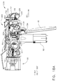
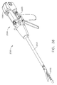
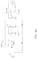
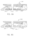
- FIGS. 1-6 depict a motor-driven surgical cutting and fastening instrument 10 that may or may not be reused.
- the instrument 10 includes a housing 12 that comprises a handle 14 that is configured to be grasped, manipulated and actuated by the clinician.
- the housing 12 is configured for operable attachment to an interchangeable shaft assembly 200 that has a surgical end effector 300 operably coupled thereto that is configured to perform one or more surgical tasks or procedures.
- an interchangeable shaft assembly 200 that has a surgical end effector 300 operably coupled thereto that is configured to perform one or more surgical tasks or procedures.
- housing may also encompass a housing or similar portion of a robotic system that houses or otherwise operably supports at least one drive system that is configured to generate and apply at least one control motion which could be used to actuate the interchangeable shaft assemblies disclosed herein and their respective equivalents.
- frame may refer to a portion of a handheld surgical instrument.
- frame may also represent a portion of a robotically controlled surgical instrument and/or a portion of the robotic system that may be used to operably control a surgical instrument.
- the interchangeable shaft assemblies disclosed herein may be employed with various robotic systems, instruments, components and methods disclosed in U.S. Patent Application Serial No.
- the housing 12 depicted in FIGS. 1-3 is shown in connection with an interchangeable shaft assembly 200 that includes an end effector 300 that comprises a surgical cutting and fastening device that is configured to operably support a surgical staple cartridge 304 therein.
- the housing 12 may be configured for use in connection with interchangeable shaft assemblies that include end effectors that are adapted to support different sizes and types of staple cartridges, have different shaft lengths, sizes, and types, etc.
- the housing 12 may also be effectively employed with a variety of other interchangeable shaft assemblies including those assemblies that are configured to apply other motions and forms of energy such as radio frequency (RF) energy, ultrasonic energy and/or motion to end effector arrangements adapted for use in connection with various surgical applications and procedures.
- RF radio frequency
- end effectors, shaft assemblies, handles, surgical instruments, and/or surgical instrument systems can utilize any suitable fastener, or fasteners, to fasten tissue.
- a fastener cartridge comprising a plurality of fasteners removably stored therein can be removably inserted into and/or attached to the end effector of a shaft assembly.
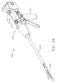
- FIG. 1 illustrates the surgical instrument 10 with an interchangeable shaft assembly 200 operably coupled thereto.
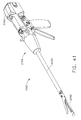
- FIGS. 2 and 3 illustrate attachment of the interchangeable shaft assembly 200 to the housing 12 or handle 14.
- the handle 14 comprises a pair of interconnectable handle housing segments 16 and 18 that may be interconnected by screws, snap features, adhesive, etc.
- the handle housing segments 16, 18 cooperate to form a pistol grip portion 19 that can be gripped and manipulated by the clinician.
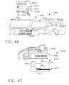
- the handle 14 operably supports a plurality of drive systems therein that are configured to generate and apply various control motions to corresponding portions of the interchangeable shaft assembly that is operably attached thereto.
- the handle 14 further includes a frame 20 that operably supports a plurality of drive systems.
- the frame 20 operably supports a "first" or closure drive system, generally designated as 30, which may be employed to apply closing and opening motions to the interchangeable shaft assembly 200 that is operably attached or coupled thereto.
- the closure drive system 30 includes an actuator in the form of a closure trigger 32 that is pivotally supported by the frame 20. More specifically, as illustrated in FIG. 4 , the closure trigger 32 is pivotally coupled to the housing 14 by a pin 33.
- the closure drive system 30 further includes a closure linkage assembly 34 that is pivotally coupled to the closure trigger 32.
- the closure linkage assembly 34 includes a first closure link 36 and a second closure link 38 that are pivotally coupled to the closure trigger 32 by a pin 35.
- the second closure link 38 may also be referred to herein as an "attachment member” and includes a transverse attachment pin 37.
- the first closure link 36 has a locking wall or end 39 thereon that is configured to cooperate with a closure release assembly 60 that is pivotally coupled to the frame 20.
- the closure release assembly 60 comprises a release button assembly 62 that has a distally protruding locking pawl 64 formed thereon.
- the release button assembly 62 may be pivoted in a counterclockwise direction by a release spring (not shown).
- a release spring not shown.
- the closure release assembly 60 serves to lock the closure trigger 32 in the fully actuated position.
- the clinician desires to unlock the closure trigger 32 to permit it to be biased to the unactuated position, the clinician simply pivots the closure release button assembly 62 such that the locking pawl 64 is moved out of engagement with the locking wall 39 on the first closure link 36.
- the closure trigger 32 may pivot back to the unactuated position.
- Other closure trigger locking and release arrangements may also be employed.
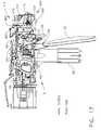
- FIGS. 13-15 illustrate the closure trigger 32 in its unactuated position which is associated with an open, or unclamped, configuration of the shaft assembly 200 in which tissue can be positioned between the jaws of the shaft assembly 200.
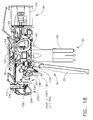
- FIGS. 16-18 illustrate the closure trigger 32 in its actuated position which is associated with a closed, or clamped, configuration of the shaft assembly 200 in which tissue is clamped between the jaws of the shaft assembly 200.
- FIGS. 14 and 17 the reader will appreciate that, when the closure trigger 32 is moved from its unactuated position ( FIG. 14 ) to its actuated position ( FIG. 17 ), the closure release button 62 is pivoted between a first position ( FIG. 14 ) and a second position ( FIG. 17 ).
- the rotation of the closure release button 62 can be referred to as being an upward rotation; however, at least a portion of the closure release button 62 is being rotated toward the circuit board 100.
- the closure release button 62 can include an arm 61 extending therefrom and a magnetic element 63, such as a permanent magnet mounted to the arm 61.
- a magnetic element 63 such as a permanent magnet mounted to the arm 61.
- the circuit board 100 includes at least one sensor configured to detect the movement of the magnetic element 63.
- a Hall effect sensor 65 can be mounted to the bottom surface of the circuit board 100. The Hall effect sensor 65 is configured to detect changes in a magnetic field surrounding the Hall effect sensor 65 caused by the movement of the magnetic element 63.
- the Hall effect sensor 65 is in signal communication with a microcontroller 7004 ( FIG. 59 ) which can determine whether the closure release button 62 is in its first position, which is associated with the unactuated position of the closure trigger 32 and the open configuration of the end effector, its second position, which is associated with the actuated position of the closure trigger 32 and the closed configuration of the end effector, and/or any position between the first position and the second position.
- a microcontroller 7004 FIG. 59
- the handle 14 and the frame 20 operably support another drive system referred to herein as a firing drive system 80 that is configured to apply firing motions to corresponding portions of the interchangeable shaft assembly attached thereto.
- the firing drive system may 80 also be referred to herein as a "second drive system”.
- the firing drive system 80 employs an electric motor 82, located in the pistol grip portion 19 of the handle 14.
- the motor 82 may be a DC brushed driving motor having a maximum rotation of, approximately, 25,000 RPM.
- the motor may include a brushless motor, a cordless motor, a synchronous motor, a stepper motor, or any other suitable electric motor.
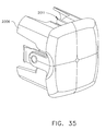
- the motor 82 is powered by a power source 90 that may comprise a removable power pack 92. As can be seen in FIG.
- the power pack 92 may comprise a proximal housing portion 94 that is configured for attachment to a distal housing portion 96.
- the proximal housing portion 94 and the distal housing portion 96 are configured to operably support a plurality of batteries 98 therein.
- Batteries 98 may each comprise a Lithium Ion ("LI") or other suitable battery.
- the distal housing portion 96 is configured for removable operable attachment to a control circuit board assembly 100 which is also operably coupled to the motor 82.
- a number of batteries 98 may be connected in series may be used as the power source for the surgical instrument 10.
- the power source 90 may be replaceable and/or rechargeable.
- the electric motor 82 includes a rotatable shaft (not shown) that operably interfaces with a gear reducer assembly 84 that is mounted in meshing engagement with a with a set, or rack, of drive teeth 122 on a longitudinally-movable drive member 120.
- a voltage polarity provided by the power source 90 operates the electric motor 82 in a clockwise direction wherein the voltage polarity applied to the electric motor by the battery can be reversed in order to operate the electric motor 82 in a counter-clockwise direction.
- the drive member 120 will be axially driven in the distal direction "DD".
- the handle 14 includes a switch which can be configured to reverse the polarity applied to the electric motor 82 by the power source 90.
- the handle 14 can also include a sensor that is configured to detect the position of the drive member 120 and/or the direction in which the drive member 120 is being moved.
- Actuation of the motor 82 is controlled by a firing trigger 130 that is pivotally supported on the handle 14.
- the firing trigger 130 can be pivoted between an unactuated position and an actuated position.
- the firing trigger 130 is biased into the unactuated position by a spring 132 or other biasing arrangement such that when the clinician releases the firing trigger 130, it is pivoted or otherwise returned to the unactuated position by the spring 132 or biasing arrangement.
- the firing trigger 130 is positioned "outboard" of the closure trigger 32 as was discussed above.
- a firing trigger safety button 134 is pivotally mounted to the closure trigger 32 by pin 35.
- the safety button 134 is positioned between the firing trigger 130 and the closure trigger 32 and has a pivot arm 136 protruding therefrom. See FIG. 4 .
- the safety button 134 When the closure trigger 32 is in the unactuated position, the safety button 134 is contained in the handle 14 where the clinician cannot readily access it and move it between a safety position preventing actuation of the firing trigger 130 and a firing position wherein the firing trigger 130 can be fired. As the clinician depresses the closure trigger 32, the safety button 134 and the firing trigger 130 pivot down wherein they can then be manipulated by the clinician.
- the handle 14 includes a closure trigger 32 and a firing trigger 130.
- the firing trigger 130 is pivotably mounted to the closure trigger 32.
- the closure trigger 32 includes an arm 31 extending therefrom and the firing trigger 130 is pivotably mounted to the arm 31 about a pivot pin 33.
- the closure trigger 32 is moved from its unactuated position ( FIG. 14 ) to its actuated position ( FIG. 17 )
- the firing trigger 130 descends downwardly, as outlined above.
- the firing trigger 130 can be depressed to operate the motor of the surgical instrument firing system.
- the handle 14 can include a tracking system, such as system 800 configured to determine the position of the closure trigger 32 and/or the position of the firing trigger 130.
- a tracking system 800 includes a magnetic element, such as permanent magnet 802which is mounted to an arm 801 extending from the firing trigger 130.
- the tracking system 800 comprises one or more sensors, such as a first Hall effect sensor 803 and a second Hall effect sensor 804which are configured to track the position of the magnet 802. Upon comparing FIGS.
- the reader will appreciate that, when the closure trigger 32 is moved from its unactuated position to its actuated position, the magnet 802 moves between a first position adjacent the first Hall effect sensor 803 and a second position adjacent the second Hall effect sensor 804.
- FIGS. 17 and 18A the reader will further appreciate that, when the firing trigger 130 is moved from an unfired position ( FIG. 17 ) to a fired position ( FIG. 18A ), the magnet 802 moves relative to the second Hall effect sensor 804.
- the sensors 803 and 804 track the movement of the magnet 802 and are in signal communication with a microcontroller on the circuit board 100.
- the microcontroller can determine the position of the magnet 802 along a predefined path and, based on that position, the microcontroller can determine whether the closure trigger 32 is in its unactuated position, its actuated position, or a position therebetween.
- the microcontroller can determine the position of the magnet 802 along a predefined path and, based on that position, the microcontroller can determine whether the firing trigger 130 is in its unfired position, its fully fired position, or a position therebetween.
- the longitudinally movable drive member 120 has a rack of teeth 122 formed thereon for meshing engagement with a corresponding drive gear 86 of the gear reducer assembly 84.
- a manually-actuatable "bailout” assembly 140 is configured to enable the clinician to manually retract the longitudinally movable drive member 120 should the motor 82 become disabled.
- An exemplary bailout assembly 140 includes a lever or bailout handle assembly 142 that is configured to be manually pivoted into ratcheting engagement with teeth 124 also provided in the drive member 120.
- the clinician can manually retract the drive member 120 by using the bailout handle assembly 142 to ratchet the drive member 120 in the proximal direction "PD".
- US 2010/0089970 discloses bailout arrangements and other components, arrangements and systems that may also be employed with the instruments disclosed herein.
- U.S. Patent Application Serial No. 12/249,117 entitled POWERED SURGICAL CUTTING AND STAPLING APPARATUS WITH MANUALLY RETRACTABLE FIRING SYSTEM, now U.S. Patent Application Publication No. 2010/0089970 , is hereby incorporated by reference in its entirety.
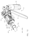
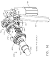
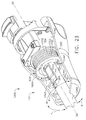
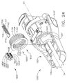
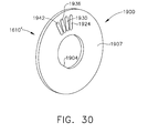
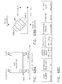
- the interchangeable shaft assembly 200 includes a surgical end effector 300 that comprises an elongated channel 302 that is configured to operably support a staple cartridge 304 therein.
- the end effector 300 further includes an anvil 306 that is pivotally supported relative to the elongated channel 302.
- the interchangeable shaft assembly 200 further includes an articulation joint 270 and an articulation lock 350 ( FIG. 8 ) which is configured to releasably hold the end effector 300 in a desired position relative to a shaft axis SA-SA. Details regarding the construction and operation of the end effector 300, the articulation joint 270 and the articulation lock 350 are set forth in U.S. Patent Application Serial No.
- the interchangeable shaft assembly 200 further includes a proximal housing or nozzle 201 comprised of nozzle portions 202 and 203.
- the interchangeable shaft assembly 200 further includes a closure tube 260 which is utilized to close and/or open the anvil 306 of the end effector 300.
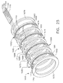
- the shaft assembly 200 includes a spine 210 which can be configured to fixably support a shaft frame portion 212 of the articulation lock 350. See FIG. 8 .
- the spine 210 is configured to, one, slidably support a firing member 220 therein and, two, slidably support the closure tube 260 which extends around the spine 210.
- the spine 210 is also configured to slidably support a proximal articulation driver 230.
- the articulation driver 230 has a distal end 231 that is configured to operably engage the articulation lock 350.
- the articulation lock 350 interfaces with an articulation frame 352 that is adapted to operably engage a drive pin (not shown) on the end effector frame (not shown).
- the spine 210 comprises a proximal end 211 which is rotatably supported in a chassis 240.
- the proximal end 211 of the spine 210 has a thread 214 formed thereon for threaded attachment to a spine bearing 216 configured to be supported within the chassis 240. See FIG. 7 .
- Such an arrangement facilitates rotatable attachment of the spine 210 to the chassis 240 such that the spine 210 may be selectively rotated about a shaft axis SA-SA relative to the chassis 240.
- the interchangeable shaft assembly 200 includes a closure shuttle 250 that is slidably supported within the chassis 240 such that it may be axially moved relative thereto.
- the closure shuttle 250 includes a pair of proximally-protruding hooks 252 that are configured for attachment to the attachment pin 37 that is attached to the second closure link 38 as will be discussed in further detail below.
- a proximal end 261 of the closure tube 260 is coupled to the closure shuttle 250 for relative rotation thereto.
- a U shaped connector 263 is inserted into an annular slot 262 in the proximal end 261 of the closure tube 260 and is retained within vertical slots 253 in the closure shuttle 250. See FIG.
- Such an arrangement serves to attach the closure tube 260 to the closure shuttle 250 for axial travel therewith while enabling the closure tube 260 to rotate relative to the closure shuttle 250 about the shaft axis SA-SA.
- a closure spring 268 is journaled on the closure tube 260 and serves to bias the closure tube 260 in the proximal direction "PD" which can serve to pivot the closure trigger into the unactuated position when the shaft assembly is operably coupled to the handle 14.
- the interchangeable shaft assembly 200 further includes an articulation joint 270.
- Other interchangeable shaft assemblies may be used that are not capable of articulation.
- the articulation joint 270 includes a double pivot closure sleeve assembly 271.
- the double pivot closure sleeve assembly 271 includes an end effector closure sleeve assembly 272 having upper and lower distally projecting tangs 273, 274.
- An end effector closure sleeve assembly 272 includes a horseshoe aperture 275 and a tab 276 for engaging an opening tab on the anvil 306 in the various manners described in U.S. Patent Application Serial No.
- An upper double pivot link 277 includes upwardly projecting distal and proximal pivot pins that engage respectively an upper distal pin hole in the upper proximally projecting tang 273 and an upper proximal pin hole in an upper distally projecting tang 264 on the closure tube 260.
- a lower double pivot link 278 includes upwardly projecting distal and proximal pivot pins that engage respectively a lower distal pin hole in the lower proximally projecting tang 274 and a lower proximal pin hole in the lower distally projecting tang 265. See also FIG. 8 .
- the closure tube 260 is translated distally (direction "DD") to close the anvil 306 in response to the actuation of the closure trigger 32.
- the anvil 306 is closed by distally translating the closure tube 260 and thus the shaft closure sleeve assembly 272, causing it to strike a proximal surface on the anvil 360 in the manner described in the aforementioned reference U.S. Patent Application Serial No. 13/803,086 .
- the anvil 306 is opened by proximally translating the closure tube 260 and the shaft closure sleeve assembly 272, causing tab 276 and the horseshoe aperture 275 to contact and push against the anvil tab to lift the anvil 306.
- the shaft closure tube 260 In the anvil-open position, the shaft closure tube 260 is moved to its proximal position.
- the surgical instrument 10 may further include an articulation lock 350 of the types and construction described in further detail in U.S. Patent Application Serial No. 13/803,086 which is configured and operated to selectively lock the end effector 300 in position.
- an articulation lock 350 of the types and construction described in further detail in U.S. Patent Application Serial No. 13/803,086 which is configured and operated to selectively lock the end effector 300 in position.
- Such arrangement enables the end effector 300 to be rotated, or articulated, relative to the shaft closure tube 260 when the articulation lock 350 is in its unlocked state. In such an unlocked state, the end effector 300 can be positioned and pushed against soft tissue and/or bone surrounding the surgical site within the patient in order to cause the end effector 300 to articulate relative to the closure tube 260.
- the end effector 300 may also be articulated relative to the closure tube 260 by an articulation driver 230.
- the interchangeable shaft assembly 200 further includes a firing member 220 that is supported for axial travel within the shaft spine 210.
- the firing member 220 includes an intermediate firing shaft portion 222 that is configured for attachment to a distal cutting portion or knife bar 280.
- the firing member 220 may also be referred to herein as a "second shaft” and/or a "second shaft assembly”.
- the intermediate firing shaft portion 222 includes a longitudinal slot 223 in the distal end thereof which is configured to receive a tab 284 on the proximal end 282 of the distal knife bar 280.
- the longitudinal slot 223 and the proximal end 282 are sized and configured to permit relative movement therebetween and comprise a slip joint 286.
- the slip joint 286 permits the intermediate firing shaft portion 222 of the firing drive 220 to be moved to articulate the end effector 300 without moving, or at least substantially moving, the knife bar 280.
- the intermediate firing shaft portion 222 can be advanced distally until a proximal sidewall of the longitudinal slot 223 comes into contact with the tab 284 in order to advance the knife bar 280 and fire the staple cartridge positioned within the channel 302
- the shaft spine 210 has an elongate opening or window 213 therein to facilitate assembly and insertion of the intermediate firing shaft portion 222 into the shaft frame 210.
- a top frame segment 215 is engaged with the shaft frame 212 to enclose the intermediate firing shaft portion 222 and knife bar 280 therein. Further description of the operation of the firing member 220 may be found in U.S. Patent Application Serial No. 13/803,086 .
- the shaft assembly 200 includes a clutch assembly 400 which is configured to selectively and releasably couple the articulation driver 230 to the firing member 220.
- the clutch assembly 400 includes a lock collar, or sleeve 402, positioned around the firing member 220 wherein the lock sleeve 402 can be rotated between an engaged position in which the lock sleeve 402 couples the articulation driver 360 to the firing member 220 and a disengaged position in which the articulation driver 360 is not operably coupled to the firing member 200.
- lock sleeve 402 When lock sleeve 402 is in its engaged position, distal movement of the firing member 220 can move the articulation driver 360 distally and, correspondingly, proximal movement of the firing member 220 can move the articulation driver 230 proximally.
- lock sleeve 402 When lock sleeve 402 is in its disengaged position, movement of the firing member 220 is not transmitted to the articulation driver 230 and, as a result, the firing member 220 can move independently of the articulation driver 230.
- the articulation driver 230 can be held in position by the articulation lock 350 when the articulation driver 230 is not being moved in the proximal or distal directions by the firing member 220.
- the lock sleeve 402 comprises a cylindrical, or an at least substantially cylindrical, body including a longitudinal aperture 403 defined therein configured to receive the firing member 220.
- the lock sleeve 402 comprises diametrically-opposed, inwardly-facing lock protrusions 404 and an outwardly-facing lock member 406.
- the lock protrusions 404 are configured to be selectively engaged with the firing member 220.
- the lock protrusions 404 are positioned within a drive notch 224 defined in the firing member 220 such that a distal pushing force and/or a proximal pulling force can be transmitted from the firing member 220 to the lock sleeve 402.
- the second lock member 406 is received within a drive notch 232 defined in the articulation driver 230 such that the distal pushing force and/or the proximal pulling force applied to the lock sleeve 402 can be transmitted to the articulation driver 230.
- the firing member 220, the lock sleeve 402, and the articulation driver 230 will move together when the lock sleeve 402 is in its engaged position.
- the lock protrusions 404 is not positioned within the drive notch 224 of the firing member 220 and, as a result, a distal pushing force and/or a proximal pulling force is not transmitted from the firing member 220 to the lock sleeve 402.
- the distal pushing force and/or the proximal pulling force are not transmitted to the articulation driver 230.
- the firing member 220 can be slid proximally and/or distally relative to the lock sleeve 402 and the proximal articulation driver 230.
- the shaft assembly 200 further includes a switch drum 500 that is rotatably received on the closure tube 260.
- the switch drum 500 comprises a hollow shaft segment 502 that has a shaft boss 504 formed thereon for receive an outwardly protruding actuation pin 410 therein.
- the actuation pin 410 extends through a slot 267 into a longitudinal slot 408 provided in the lock sleeve 402 to facilitate axial movement of the lock sleeve 402 when it is engaged with the articulation driver 230.
- a rotary torsion spring 420 is configured to engage the boss 504 on the switch drum 500 and a portion of the nozzle housing 203 as shown in FIG. 10 to apply a biasing force to the switch drum 500.
- the switch drum 500 further comprises at least partially circumferential openings 506 defined therein which, referring to FIGS. 5 and 6 , are configured to receive circumferential mounts 204, 205 extending from the nozzle halves 202, 203 and permit relative rotation, but not translation, between the switch drum 500 and the proximal nozzle 201.
- the mounts 204 and 205 also extend through openings 266 in the closure tube 260 to be seated in recesses 211 in the shaft spine 210.
- rotation of the nozzle 201 to a point where the mounts 204, 205 reach the end of their respective slots 506 in the switch drum 500 will result in rotation of the switch drum 500 about the shaft axis SA-SA.
- the nozzle 201 may be employed to operably engage and disengage the articulation drive system with the firing drive system in the various manners described in further detail in U.S. Patent Application Serial No. 13/803,086 .
- the shaft assembly 200 comprises a slip ring assembly 600 which is configured to conduct electrical power to and/or from the end effector 300 and/or communicate signals to and/or from the end effector 300.
- the slip ring assembly 600 comprises a proximal connector flange 604 mounted to a chassis flange 242 extending from the chassis 240 and a distal connector flange 601 positioned within a slot defined in the shaft housings 202, 203.
- the proximal connector flange 604 comprises a first face and the distal connector flange 601 comprises a second face which is positioned adjacent to and movable relative to the first face.
- the distal connector flange 601 can rotate relative to the proximal connector flange 604 about the shaft axis SA-SA.
- the proximal connector flange 604 comprises a plurality of concentric, or at least substantially concentric, conductors 602 defined in the first face thereof.
- a connector 607 is mounted on the proximal side of the connector flange 601 and has a plurality of contacts (not shown) wherein each contact corresponds to and is in electrical contact with one of the conductors 602. Such an arrangement permits relative rotation between the proximal connector flange 604 and the distal connector flange 601 while maintaining electrical contact therebetween.
- the proximal connector flange 604 includes an electrical connector 606 which places the conductors 602 in signal communication with a shaft circuit board 610 mounted to the shaft chassis 240.
- a wiring harness comprising a plurality of conductors extends between the electrical connector 606 and the shaft circuit board 610.
- the electrical connector 606 extend proximally through a connector opening 243 defined in the chassis mounting flange 242. See FIG. 7 .
- U.S. Patent Application Serial No. 13/800,067 entitled STAPLE CARTRIDGE TISSUE THICKNESS SENSOR SYSTEM, filed on March 13, 2013, is incorporated by reference in its entirety.
- the shaft assembly 200 includes a proximal portion which is fixably mounted to the handle 14 and a distal portion which is rotatable about a longitudinal axis.
- the rotatable distal shaft portion can be rotated relative to the proximal portion about the slip ring assembly 600, as discussed above.
- the distal connector flange 601 of the slip ring assembly 600 is positioned within the rotatable distal shaft portion.
- the switch drum 500 is also positioned within the rotatable distal shaft portion. When the rotatable distal shaft portion is rotated, the distal connector flange 601 and the switch drum 500 are rotated synchronously with one another.
- the switch drum 500 can be rotated between a first position and a second position relative to the distal connector flange 601.
- the articulation drive system is operably disengaged from the firing drive system and, thus, the operation of the firing drive system does not articulate the end effector 300 of the shaft assembly 200.
- the switch drum 500 is in its second position, the articulation drive system is operably engaged with the firing drive system and, thus, the operation of the firing drive system articulates the end effector 300 of the shaft assembly 200.
- the switch drum 500 is moved between its first position and its second position, the switch drum 500 is moved relative to distal connector flange 601.
- the shaft assembly 200 comprises at least one sensor configured to detect the position of the switch drum 500.
- the distal connector flange 601 comprises a Hall effect sensor 605 and the switch drum 500 comprises a magnetic element, such as permanent magnet 505.
- the Hall effect sensor 605 is configured to detect the position of the permanent magnet 505. When the switch drum 500 is rotated between its first position and its second position, the permanent magnet 505 moves relative to the Hall effect sensor 605.
- the Hall effect sensor 605 detects changes in a magnetic field created when the permanent magnet 505 is moved.
- the Hall effect sensor 605 is in signal communication with the shaft circuit board 610 and/or the handle circuit board 100. Based on the signal from the Hall effect sensor 605, a microcontroller on the shaft circuit board 610 and/or the handle circuit board 100 can determine whether the articulation drive system is engaged with or disengaged from the firing drive system.
- the chassis 240 includes at least one, and preferably two, tapered attachment portions 244 formed thereon that are adapted to be received within corresponding dovetail slots 702 formed within a distal attachment flange portion 700 of the frame 20.
- Each dovetail slot 702 is tapered or, stated another way, is somewhat V-shaped to seatingly receive the attachment portions 244 therein.
- a shaft attachment lug 226 is formed on the proximal end of the intermediate firing shaft 222.
- the shaft attachment lug 226 is received in a firing shaft attachment cradle 126 formed in the distal end 125 of the longitudinal drive member 120. See FIGS. 3 and 6 .
- Various shaft assembly embodiments employ a latch system 710 for removably coupling the shaft assembly 200 to the housing 12 and more specifically to the frame 20.
- the latch system 710 includes a lock member or lock yoke 712 that is movably coupled to the chassis 240.
- the lock yoke 712 has a U-shape with two spaced downwardly extending legs 714.
- the legs 714 each have a pivot lug 716 formed thereon that are adapted to be received in corresponding holes 245 formed in the chassis 240.
- Such arrangement facilitates pivotal attachment of the lock yoke 712 to the chassis 240.
- the lock yoke 712 includes two proximally protruding lock lugs 714 that are configured for releasable engagement with corresponding lock detents or grooves 704 in the distal attachment flange 700 of the frame 20. See FIG. 3 .
- the lock yoke 712 is biased in the proximal direction by a spring or biasing member (not shown). Actuation of the lock yoke 712 is accomplished by a latch button 722 that is slidably mounted on a latch actuator assembly 720 that is mounted to the chassis 240.
- the latch button 722 is biased in a proximal direction relative to the lock yoke 712.
- the lock yoke 712 can be moved to an unlocked position by biasing the latch button the in distal direction which also causes the lock yoke 712 to pivot out of retaining engagement with the distal attachment flange 700 of the frame 20.
- the lock lugs 716 are retainingly seated within the corresponding lock detents or grooves 704 in the distal attachment flange 700.
- an interchangeable shaft assembly that includes an end effector of the type described herein that is adapted to cut and fasten tissue, as well as other types of end effectors
- the clinician may actuate the closure trigger 32 to grasp and manipulate the target tissue into a desired position. Once the target tissue is positioned within the end effector 300 in a desired orientation, the clinician may then fully actuate the closure trigger 32 to close the anvil 306 and clamp the target tissue in position for cutting and stapling. In that instance, the first drive system 30 has been fully actuated. After the target tissue has been clamped in the end effector 300, it may be desirable to prevent the inadvertent detachment of the shaft assembly 200 from the housing 12.
- a latch system 710 is configured to prevent such inadvertent detachment.
- the lock yoke 712 includes at least one and preferably two lock hooks 718 that are adapted to contact corresponding lock lug portions 256 that are formed on the closure shuttle 250.
- the lock yoke 712 may be pivoted in a distal direction to unlock the interchangeable shaft assembly 200 from the housing 12.
- the lock hooks 718 do not contact the lock lug portions 256 on the closure shuttle 250.
- the lock yoke 712 is prevented from being pivoted to an unlocked position. See FIGS. 16-18 .
- the clinician were to attempt to pivot the lock yoke 712 to an unlocked position or the lock yoke 712 was in advertently bumped or contacted in a manner that might otherwise cause it to pivot distally, the lock hooks 718 on the lock yoke 712 will contact the lock lugs 256 on the closure shuttle 250 and prevent movement of the lock yoke 712 to an unlocked position.
- Attachment of the interchangeable shaft assembly 200 to the handle 14 will now be described with reference to FIG. 3 .
- the clinician positions the chassis 240 of the interchangeable shaft assembly 200 above or adjacent to the distal attachment flange 700 of the frame 20 such that the tapered attachment portions 244 formed on the chassis 240 are aligned with the dovetail slots 702 in the frame 20.
- the clinician then moves the shaft assembly 200 along an installation axis IA that is perpendicular to the shaft axis SA-SA to seat the attachment portions 244 in "operable engagement" with the corresponding dovetail receiving slots 702.
- the shaft attachment lug 226 on the intermediate firing shaft 222 will also be seated in the cradle 126 in the longitudinally movable drive member 120 and the portions of pin 37 on the second closure link 38 will be seated in the corresponding hooks 252 in the closure yoke 250.
- operble engagement in the context of two components means that the two components are sufficiently engaged with each other so that upon application of an actuation motion thereto, the components may carry out their intended action, function and/or procedure.
- a first system comprises a frame system which couples and/or aligns the frame or spine of the shaft assembly 200 with the frame 20 of the handle 14.
- Another system comprises a closure drive system 30 which can operably connect the closure trigger 32 of the handle 14 and the closure tube 260 and the anvil 306 of the shaft assembly 200.
- the closure tube attachment yoke 250 of the shaft assembly 200 is engaged with the pin 37 on the second closure link 38.
- Another system comprises the firing drive system 80 which operably connects the firing trigger 130 of the handle 14 with the intermediate firing shaft 222 of the shaft assembly 200.
- the shaft attachment lug 226 is operably connected with the cradle 126 of the longitudinal drive member 120.
- Another system comprises an electrical system which, one, signals to a controller in the handle 14, such as microcontroller that the shaft assembly 200 has been operably engaged with the handle 14 and/or, two, conducts power and/or communication signals between the shaft assembly 200 and the handle 14.
- the shaft assembly 200 can include an electrical connector 4010 that is operably mounted to the shaft circuit board 610.
- the electrical connector 4010 is configured for mating engagement with a corresponding electrical connector 4000 on the handle control board 100. Further details regaining the circuitry and control systems may be found in U.S. Patent Application Serial No. 13/803,086 , the entire disclosure of which was previously incorporated by reference herein.
- the fifth system consists of the latching system for releasably locking the shaft assembly 200 to the handle 14.
- an exemplary electrical connector 4000 comprises a first contact 4001a, a second contact 4001b, a third contact 4001c, a fourth contact 4001d, a fifth contact 4001e, and a sixth contact 4001f. While the illustrated embodiment utilizes six contacts, other embodiments are envisioned which may utilize more than six contacts or fewer than six contacts.
- the first contact 4001a is in electrical communication with a transistor 4008, contacts 4001b-4001e are in electrical communication with a microcontroller 7004, and the sixth contact 4001f is in electrical communication with a ground.
- One or more of the electrical contacts 4001b-4001e is in electrical communication with one or more output channels of the microcontroller 7004 and can be energized, or have a voltage potential applied thereto, when the handle 1042 is in a powered state.
- One or more of the electrical contacts 4001b-4001e is in electrical communication with one or more input channels of the microcontroller 7004 and, when the handle 14 is in a powered state, the microcontroller 7004 is configured to detect when a voltage potential is applied to such electrical contacts.
- a shaft assembly such as shaft assembly 200 is assembled to the handle 14, the electrical contacts 4001a-4001f are not in communication with each other.
- the electrical contacts 4001a-4001f of the electrical connector 4000 are exposed and, one or more of the contacts 4001a-4001f may be accidentally placed in electrical communication with each other. Such circumstances can arise when one or more of the contacts 4001a-4001f come into contact with an electrically conductive material.
- the microcontroller 7004 can receive an erroneous input and/or the shaft assembly 200 can receive an erroneous output.
- the handle 14 may be unpowered when a shaft assembly, such as shaft assembly 200is not attached to the handle 14.
- the handle 1042 can be powered when a shaft assembly, such as shaft assembly 200 is not attached thereto and the microcontroller 7004 is configured to ignore inputs, or voltage potentials, applied to the contacts in electrical communication with the microcontroller 7004, e.g., contacts 4001b-4001euntil a shaft assembly is attached to the handle 14. Even though the microcontroller 7004 may be supplied with power to operate other functionalities of the handle 14, the handle 14 may be in a powered-down state. In a way, the electrical connector 4000 may be in a powered-down state as voltage potentials applied to the electrical contacts 4001b-4001e do not affect the operation of the handle 14.
- contacts 4001b-4001e are in a powered-down state
- the electrical contacts 4001a and 4001f which are not in electrical communication with the microcontroller 7004, may not be in a powered-down state.
- sixth contact 4001f may remain in electrical communication with a ground regardless of whether the handle 14 is in a powered-up or a powered-down state.
- the transistor 4008, and/or any other suitable arrangement of transistors, such as transistor 4010 and/or switches may be configured to control the supply of power from a power source 4004, such as a battery 90 within the handle 14 to the first electrical contact 4001a regardless of whether the handle 14 is in a powered-up or a powered-down state.
- the shaft assembly 200 can be configured to change the state of the transistor 4008 when the shaft assembly 200 is engaged with the handle 14.
- a Hall effect sensor 4002 can be configured to switch the state of transistor 4010 which, as a result, switches the state of transistor 4008 and ultimately supplies power from power source 4004 to first contact 4001a. In this way, both the power circuits and the signal circuits to the connector 4000 are powered down when a shaft assembly is not installed to the handle 14 and powered up when a shaft assembly is installed to the handle 14.
- the handle 14 includes the Hall effect sensor 4002 which is configured to detect a detectable element, such as a magnetic element 4007 ( FIG. 3 )on a shaft assembly, such as shaft assembly 200when the shaft assembly is coupled to the handle 14.
- the Hall effect sensor 4002 is powered by a power source 4006, such as a batterywhich, in effect, amplifies the detection signal of the Hall effect sensor 4002 and communicates with an input channel of the microcontroller 7004 via the circuit illustrated in FIG. 59 .
- the microcontroller 7004 can enter into its normal, or powered-up, operating state. In such an operating state, the microcontroller 7004 will evaluate the signals transmitted to one or more of the contacts 4001b-4001e from the shaft assembly and/or transmit signals to the shaft assembly through one or more of the contacts 4001b-4001e in normal use thereof.
- the shaft assembly 1200 may have to be fully seated before the Hall effect sensor 4002 can detect the magnetic element 4007.
- a Hall effect sensor 4002 can be utilized to detect the presence of the shaft assembly 200
- any suitable system of sensors and/or switches can be utilized to detect whether a shaft assembly has been assembled to the handle 14. In this way, both the power circuits and the signal circuits to the connector 4000 can be powered down when a shaft assembly is not installed to the handle 14 and powered up when a shaft assembly is installed to the handle 14.
- any number of magnetic sensing elements may be employed to detect whether a shaft assembly has been assembled to the handle 14.
- the technologies used for magnetic field sensing include search coil, fluxgate, optically pumped, nuclear precession, SQUID, Hall-effect, anisotropic magnetoresistance, giant magnetoresistance, magnetic tunnel junctions, giant magnetoimpedance, magnetostrictive/piezoelectric composites, magnetodiode, magnetotransistor, fiber optic, magnetooptic, and microelectromechanical systems-based magnetic sensors, among others.
- the microcontroller 7004 generally comprises a microprocessor ("processor") and one or more memory units operationally coupled to the processor. By executing instruction code stored in the memory, the processor controls various components of the surgical instrument, such as the motor, various drive systems, and/or a user display.
- the microcontroller 7004 may be implemented using integrated and/or discrete hardware elements, software elements, and/or a combination of both.
- Examples of integrated hardware elements include processors, microprocessors, microcontrollers, integrated circuits, application specific integrated circuits (ASIC), programmable logic devices (PLD), digital signal processors (DSP), field programmable gate arrays (FPGA), logic gates, registers, semiconductor devices, chips, microchips, chip sets, microcontrollers, system-on-chip (SoC), and/or system-in-package (SIP).
- Examples of discrete hardware elements may include circuits and/or circuit elements such as logic gates, field effect transistors, bipolar transistors, resistors, capacitors, inductors, and/or relays.
- the microcontroller 7004 may include a hybrid circuit comprising discrete and integrated circuit elements or components on one or more substrates.
- the microcontroller 7004 may be an LM 4F230H5QR, available from Texas Instruments.
- the Texas Instruments LM4F230H5QR is an ARM Cortex-M4F Processor Core comprising on-chip memory of 256 KB single-cycle flash memory, or other non-volatile memory, up to 40 MHz, a prefetch buffer to improve performance above 40 MHz, a 32 KB single-cycle serial random access memory (SRAM), internal read-only memory (ROM) loaded with StellarisWare ® software, 2KB electrically erasable programmable read-only memory (EEPROM), one or more pulse width modulation (PWM) modules, one or more quadrature encoder inputs (QEI) analog, one or more 12-bit Analog-to-Digital Converters (ADC) with 12 analog input channels, among other features that are readily available.
- Other microcontrollers may be readily substituted for use with the present disclosure. Accordingly, the present disclosure should not be limited in this context.
- the handle 14 and/or the shaft assembly 200 include systems and configurations configured to prevent, or at least reduce the possibility of, the contacts of the handle electrical connector 4000 and/or the contacts of the shaft electrical connector 4010 from becoming shorted out when the shaft assembly 200 is not assembled, or completely assembled, to the handle 14.
- the handle electrical connector 4000 is at least partially recessed within a cavity 4009 defined in the handle frame 20.
- the six contacts 4001a-4001f of the electrical connector 4000 are completely recessed within the cavity 4009. Such arrangements reduce the possibility of an object accidentally contacting one or more of the contacts 4001a-4001f.
- the shaft electrical connector 4010 are positioned within a recess defined in the shaft chassis 240 which reduces the possibility of an object accidentally contacting one or more of the contacts 4011a-4011f of the shaft electrical connector 4010.
- the shaft contacts 4011a-4011f comprise male contacts.
- Each shaft contact 4011a-4011f may comprise a flexible projection extending therefrom which can be configured to engage a corresponding handle contact 4001a-4001f.
- the handle contacts 4001a-4001f comprise female contacts.
- Each handle contact 4001a-4001f can comprise a flat surface against which the male shaft contacts 4001a-4001f can wipe, or slide, and maintain an electrically conductive interface therebetween.
- the direction in which the shaft assembly 200 is assembled to the handle 14 is parallel to, or at least substantially parallel to, the handle contacts 4001a-4001f such that the shaft contacts 4011a-4011f slide against the handle contacts 4001a-4001f when the shaft assembly 200 is assembled to the handle 14.
- the handle contacts 4001a-4001f can comprise male contacts and the shaft contacts 4011a-4011f can comprise female contacts.
- the handle contacts 4001a-4001f and the shaft contacts 4011a-4011f can comprise any suitable arrangement of contacts.
- the handle 14 comprises a connector guard configured to at least partially cover the handle electrical connector 4000 and/or a connector guard configured to at least partially cover the shaft electrical connector 4010.
- a connector guard prevents, or at least reduces the possibility of, an object accidentally touching the contacts of an electrical connector when the shaft assembly is not assembled to, or only partially assembled to, the handle.
- the connector guard can be movable. For instance, the connector guard can be moved between a guarded position in which it at least partially guards a connector and an unguarded position in which it does not guard, or at least guards less of, the connector.
- the connector guard can be displaced as the shaft assembly is being assembled to the handle.
- the shaft assembly can contact and displace the handle connector guard as the shaft assembly is being assembled to the handle.
- the handle can contact and displace the shaft connector guard as the shaft assembly is being assembled to the handle.
- the connector guard can comprise a door, and the door can comprise a beveled surface which, when contacted by the handle or shaft, facilitates the displacement of the door in a certain direction.
- the connector guard can be translated and/or rotated.
- the connector guard can comprise at least one film which covers the contacts of an electrical connector and, when the shaft assembly is assembled to the handle, the film is ruptured. For example, the male contacts of a connector can penetrate the film before engaging the corresponding contacts positioned underneath the film.
- the surgical instrument includes a system which can selectively power-up, or activate, the contacts of an electrical connector, such as the electrical connector 4000.
- the contacts can be transitioned between an unactivated condition and an activated condition.
- the contacts can be transitioned between a monitored condition, a deactivated condition, and an activated condition.
- the microcontroller 7004 can monitor the contacts 4001a-4001f when a shaft assembly has not been assembled to the handle 14 to determine whether one or more of the contacts 4001a-4001f may have been shorted.
- the microcontroller 7004 is configured to apply a low voltage potential to each of the contacts 4001a-4001f and assess whether only a minimal resistance is present at each of the contacts.
- Such an operating state can comprise the monitored condition.
- the microcontroller 7004 deactivates that contact, more than one contact, or, alternatively, all of the contacts.
- Such an operating state can comprise the deactivated condition. If a shaft assembly is assembled to the handle 14 and it is detected by the microcontroller 7004, as discussed above, the microcontroller 7004 increases the voltage potential to the contacts 4001a-4001f. Such an operating state can comprise the activated condition.
- the various shaft assemblies disclosed herein may employ sensors and various other components that require electrical communication with the controller in the housing. These shaft assemblies generally are configured to be able to rotate relative to the housing necessitating a connection that facilitates such electrical communication between two or more components that may rotate relative to each other.
- the connector arrangements must be relatively robust in nature while also being somewhat compact to fit into the shaft assembly connector portion.
- FIGS. 19-22 depict one form of electric coupler or slip ring connector 1600 that may be employed with, for example an interchangeable shaft assembly 1200 or a variety of other applications that require electrical connections between components that rotate relative to each other.
- the shaft assembly 1200 is similar to shaft assembly 200 described herein and includes a closure tube or outer shaft 1260 and a proximal nozzle 1201 (the upper half of nozzle 1201 is omitted for clarity).
- the outer shaft 1260 is mounted on a shaft spine 1210 such that the outer tube 1260 is selectively axially movable thereon.
- the proximal ends of the shaft spine 1210 and the outer tube 1260 are rotatably coupled to a chassis 1240 for rotation relative thereto about a shaft axis SA-SA.
- the proximal nozzle 1201 includes mounts or mounting lugs 1204 ( FIG. 20 ) that protrude inwardly from the nozzle portions and extend through corresponding openings 1266 in the outer tube 1260 to be seated in corresponding recesses 1211 in the shaft spine 1210.
- mounts or mounting lugs 1204 FIG. 20
- the clinician simply rotates the nozzle 1201 as represented by arrows "R" in FIG. 19 .
- the distal electrical component 1800 is rotatable with the nozzle 1201 about the shaft axis SA-SA.
- the electrical component 1800 comprises a connector, battery, etc. that includes contacts 1802, 1804, 1806, and 1808 that are laterally displaced from each other.
- the slip ring connector 1600 further includes a mounting member 1610 that includes a cylindrical body portion 1612 that defines an annular mounting surface 1613.
- a distal flange 1614 may be formed on at least one end of the cylindrical body portion 1612.
- the body portion 1612 of the mounting member 1610 is sized to be non-rotatably mounted on a mounting hub 1241 on the chassis 1240.
- one distal flange 1614 is provided on one end of the body portion 1612.
- a second flange 1243 is formed on the chassis 1240 such that when the body portion 1612 is fixedly (non-rotatably) mounted thereon, the second flange 1243 abuts the proximal end of the body portion 1612.
- the slip ring connector 1600 also employs a unique and novel annular circuit trace assembly 1620 that is wrapped around the annular mounting surface 1613 of the body portion 1612 such that it is received between the first and second flanges 1614 and 1243.
- the circuit trace assembly 1620 comprise an adhesive-backed flexible substrate 1622 that is wrapped around the circumference of the body portion 1612 (i.e., the annular mounting surface 1613). Prior to being wrapped around the body portion 1612, the flexible substrate 1622 has a "T-shape" with a first annular portion 1624 and a lead portion 1626. As can also be seen in FIGS.
- the circuit trace assembly 1620 further includes circuit traces 1630, 1640, 1650, 1660 that comprise electrically-conductive gold-plated traces.
- circuit traces 1630, 1640, 1650, 1660 that comprise electrically-conductive gold-plated traces.
- Each electrically-conductive circuit trace includes an "annular portion” that will form an annular part of the trace when the substrate is wrapped around the body portion 1612 as well as another "lead portion” that extends transversely from or perpendicular from the annular portion. More specifically, referring to FIG. 22 , first electrically-conductive circuit trace 1630 has a first annular portion 1632 and first lead portion 1634.
- the second electrically-conductive circuit trace 1640 has a second annular portion 1642 and a second lead portion 1644 extending transversely or perpendicularly therefrom.
- the third electrically conductive circuit trace 1650 has a third annular portion 1652 and a third lead portion 1654 extending transversely or perpendicularly therefrom.
- the fourth electrically-conductive circuit trace has a fourth annular portion 1662 and a fourth lead portion 1664 extending transversely or perpendicularly therefrom.
- the electrically-conductive circuit traces 1630, 1640, 1650, 1660 may be applied to the flexible substrate 1622 while the substrate is in a planar orientation (i.e., prior to being wrapped onto the annular body portion 1612 of the mounting member 1610) using conventional manufacturing techniques. As can be seen in FIG. 22 , the annular portions 1632, 1642,1652,1662 are laterally displaced from each other. Likewise, the lead portions 1634, 1644, 1654, 1664 are laterally displaced from each other.
- the ends of the portion of the substrate that contains the annular portions 1632, 1642, 1652, 1664 are butted together such that the annular portions 1632, 1642, 1652, 1664 form discrete continuous annular electrically-conductive paths 1636, 1646, 1656, 1666, respectively that extend around the shaft axis SA-SA.
- the electrically-conductive paths 1636, 1646, 1656, and 1666 are laterally or axially displaced from each other along the shaft axis SA-SA.
- the lead portion 1626 may extend through a slot 1245 in the flange 1243 and be electrically coupled to a circuit board (see e.g., FIG. 7 - circuit board 610) or other suitable electrical component(s).
- the electrical component 1800 is mounted within the nozzle 1261 for rotation about the mounting member 1610 such that: contact 1802 is in constant electrical contact with the first annular electrically-conductive path 1636; contact 1804 is in constant electrical contact with the second annular electrically-conductive path 1646; contact 1806 is in constant electrical contact with the third annular electrically-conductive path 1656; and contact 1808 is in constant electrical contact with the fourth electrically-conductive path 1666.
- contact 1802 is in constant electrical contact with the first annular electrically-conductive path 1636
- contact 1804 is in constant electrical contact with the second annular electrically-conductive path 1646
- contact 1806 is in constant electrical contact with the third annular electrically-conductive path 1656
- contact 1808 is in constant electrical contact with the fourth electrically-conductive path 1666.
- the various advantages of the slip ring connector 1600 may also be obtained in applications wherein the mounting member 1610 is supported for rotation about the shaft axis SA-SA and the electrical component 1800 is fixedly mounted relative thereto.
- the slip ring connector 1600 may be
- the slip ring connector 1600 comprises a radial slip ring that provides a conductive contact means of passing signal(s) and power to and from any radial position and after shaft rotation.
- the electrical component comprises a battery contact
- the battery contact position can be situated relative to the mounting member to minimize any tolerance stack up between those components.
- the coupler arrangement represents a low cost coupling arrangement that can be assembled with minimal manufacturing costs.
- the gold plated traces may also minimize the likelihood of corrosion.
- the unique and novel contact arrangement facilitates complete clockwise and counterclockwise rotation about the shaft axis SA-SA while remaining in electrical contact with the corresponding annular electrically-conductive paths.
- FIGS. 23-25 depict one form of electric coupler or slip ring connector 1600' that may be employed with, for example an interchangeable shaft assembly 1200' or a variety of other applications that require electrical connections between components that rotate relative to each other.
- the shaft assembly1200' is similar to shaft assembly 1200 described herein and includes a closure tube or outer shaft 1260 and a proximal nozzle 1201 (the upper half of nozzle 1201 is omitted for clarity).
- the outer shaft 1260 is mounted on a shaft spine 1210 such that the outer tube 1260 may be selectively axially movable thereon.
- the proximal ends of the shaft spine 1210 and the outer tube 1260 are rotatably coupled to a chassis 1240' for rotation relative thereto about a shaft axis SA-SA.
- the proximal nozzle 1201 includes mounts or mounting lugs that protrude inwardly from the nozzle portions and extend through corresponding openings 1266 in the outer tube 1260 to be seated in corresponding recesses 1211 in the shaft spine 1210.
- the clinician simply rotates the nozzle 1201 as represented by arrows "R" in FIG. 23 .
- the distal electrical component 1800' is rotatable with the nozzle 1201 and the wires/traces attached thereto.
- the electrical component 1800 comprises a connector, battery, etc. that includes contacts 1802', 1804', 1806', 1808' that are laterally displaced from each other.
- the slip ring connector 1600' further includes a laminated slip ring assembly 1610' that is fabricated from a plurality of conductive rings that are laminated together. More specifically and with reference to FIG. 25 , one form of slip ring assembly 1610' comprises a first non-electrically conductive flange 1670 that forms a distal end of the slip ring assembly 1610'.
- the flange 1670 is fabricated from a high-heat resistant material.
- a first electrically conductive ring 1680 is positioned immediately adjacent the first flange 1670.
- the first electrically conductive ring 1680 comprises a first copper ring 1681 that has a first gold plating 1682 thereon.
- a second non-electrically conductive ring 1672 is adjacent to the first electrically-conductive ring 1680.
- a second electrically-conductive ring 1684 is adjacent to the second non-electrically-conductive ring 1672.
- the second electrically-conductive ring 1684 comprises a second copper ring 1685 that has a second gold plating 1686 thereon.
- a third non-electrically-conductive ring 1674 is adjacent to the second electrically-conductive ring 1684.
- a third electrically conductive ring 1688 is adjacent to the third non-electrically conductive ring 1674.
- the third electrically conductive ring 1688 comprises a third copper ring 1689 that has a third gold plating 1690 thereon.
- a fourth non-electrically conductive ring 1676 is adjacent to the third electrically-conductive ring 1688.
- a fourth electrically conductive ring 1692 is adjacent to the fourth non-electrically-conductive ring 1676.
- the fourth electrically-conductive ring 1692 is adjacent to the fourth non-electrically conductive ring 1676.
- a fifth non-electrically conductive ring 1678 is adjacent to the fourth electrically-conductive ring 1692 and forms the proximal end of the mounting member 1610'.
- the non-electrically conductive rings 1670, 1672, 1674, 1676, and 1678 may be fabricated from the same material.
- the first electrically-conductive ring 1680 forms a first annular electrically-conductive pathway 1700.
- the second electrically-conductive ring 1682 forms a second annular electrically-conductive pathway 1702 that is laterally or axially spaced from the first annular electrically-conductive pathway 1700.
- the third electrically-conductive ring 1688 forms a third annular electrically conductive pathway 1704 that is laterally or axially spaced from the second annular electrically-conductive pathway1702.
- the fourth electrically-conductive ring 1692 forms a fourth annular electrically-conductive pathway 1706 that is laterally or axially spaced from the third annular electrically-conductive pathway 1704.
- the slip ring assembly 1610' comprises a one piece molded high temperature resistant, non-conductive material with molded in channels for electromagnetic forming (EMF - Magneformed) copper rings.
- the slip ring connector 1600' further includes a non-conductive transverse mounting member 1720 that is adapted to be inserted into axially-aligned notches 1710 in each of the rings 1670, 1680, 1672, 1684, 1674, 1688, 1676, 1692, and 1678.
- the transverse mounting member 1720 has a first circuit trace 1722 thereon that is adapted for electrical contact with the first annular electrically-conductive pathway 1700 when the transverse mounting member 1672 is mounted within the notches 1710.
- a second circuit trace 1724 is printed on the transverse mounting member 1720 and is configured for electrical contact with the second annular electrically conductive pathway 1702.
- a third circuit trace 1726 is printed on the transverse mounting member 1720 and is configured for electrical contact with the third annular electrically-conductive pathway 1704.
- a fourth circuit trace 1728 is printed on the transverse mounting member 1720 and is configured for electrical contact with the fourth annular electrically-conductive pathway 1706.
- the slip ring assembly 1610' is configured to be fixedly (non-rotatably) received on a mounting hub 1241' on the chassis 1240'.
- the transverse mounting member 1720 is received within groove 1243' formed in the mounting hub 1241' which acts as a keyway for the transverse mounting member 1720 and which serves to prevent the slip ring assembly 1610' from rotating relative to the mounting hub 1241'.
- the electrical component 1800' is mounted within the nozzle 1201 for rotation about the slip ring assembly 1610' such that: contact 1802' is in constant electrical contact with the first annular electrically-conductive path 1700; contact 1804' is in constant electrical contact with the second annular electrically-conductive path 1702; contact 1806' is in constant electrical contact with the third annular electrically-conductive path 1704; and contact 1808' is in constant electrical contact with the fourth electrically-conductive path 1706.
- the various advantages of the slip ring connector 1600' may also be obtained in applications wherein the slip ring assembly 1610' is supported for rotation about the shaft axis SA-SA and the electrical component 1800' is fixedly mounted relative thereto. It will be further appreciated that the slip ring connector 1600' may be effectively employed in connection with a variety of different components and applications outside the field of surgery wherein it is desirable to provide electrical connections between components that rotate relative to each other.
- the slip ring connector 1600' comprises a radial slip ring that provides a conductive contact means of passing signal(s) and power to and from any radial position and after shaft rotation.
- the electrical component comprises a battery contact
- the battery contact position can be situated relative to the mounting member to minimize any tolerance stack-up between those components.
- the slip ring connector 1600' represents a low cost coupling arrangement that can be assembled with minimal manufacturing costs.
- the gold plated traces may also minimize the likelihood of corrosion.
- the unique and novel contact arrangement facilitates complete clockwise and counterclockwise rotation about the shaft axis while remaining in electrical contact with the corresponding annular electrically-conductive paths.
- FIGS. 26-30 depict another form of electric coupler or slip ring connector 1600" that may be employed with, for example an interchangeable shaft assembly 1200" or a variety of other applications that require electrical connections between components that rotate relative to each other.
- the shaft assembly 1200" is similar to shaft assemblies 1200 and/or 1200' described herein except for the differences noted below.
- the shaft assembly 1200" includes a closure tube or outer shaft 1260 and a proximal nozzle 1201 (the upper half of nozzle 1201 is omitted for clarity).
- the outer shaft 1260 is mounted on a shaft spine 1210 such that the outer tube 1260 is selectively axially movable thereon.
- the proximal ends of the shaft spine 1210 and the outer tube 1260 are rotatably coupled to a chassis 1240" for rotation relative thereto about a shaft axis SA-SA.
- the proximal nozzle 1201 includes mounts or mounting lugs that protrude inwardly from the nozzle portions and extend through corresponding openings 1266 in the outer tube 1260 to be seated in corresponding recesses 1211 in the shaft spine 1210.
- the clinician simply rotates the nozzle 1201.
- conductors such as wires and/or traces (not shown) are received or mounted within the outer tube 1260 or could even be routed along the outer tube 1260 from the sensors to a distal electrical component 1800"' mounted within the nozzle 1201.
- the electrical component 1800" is mounted in the nozzle 1201 such that it is substantially aligned with the shaft axis SA-SA.
- the distal electrical component 1800" is rotatable about the shaft axis SA-SA with the nozzle 1201 and the wires/traces attached thereto.
- the electrical component 1800" may comprise a connector, a battery, etc. that includes four contacts 1802", 1804", 1806", 1808" that are laterally displaced from each other.
- the slip ring connector 1600" further includes a slip ring assembly 1610" that includes a base ring 1900 that is fabricated from a non-electrically conductive material and has a central mounting bore 1902 therethrough.
- the mounting bore 1902 has a flat surface 1904 and is configured for non-rotational attachment to a mounting flange assembly 1930 that is supported at a distal end of the chassis 1240".
- a distal side 1905 of the base ring 1900 has a series of concentric electrical-conductive rings 1906, 1908, 1910, and 1912 attached or laminated thereto.
- the rings 1906, 1908, 1910, and 1912 may be attached to the base ring 1900 by any suitable method.
- the base ring 1900 further includes a circuit trace extending therethrough that is coupled to each of the electrically-conductive rings 1906, 1908, 1910, and 1912.
- a first circuit trace 1922 extends through a first hole 1920 in the base ring 1900 and is coupled to the first electrically conductive ring 1906.
- the first circuit trace 1922 terminates in a first proximal contact portion 1924 on the proximal side 1907 of the base ring 1900. See FIG. 30 .
- a second circuit trace 1928 extends through a second hole 1926 in the base ring 1900 and is coupled to the second electrically-conductive ring 1908.
- the second circuit trace 1928 terminates in a second proximal contact 1930 on the proximal side 1907 of the base ring 1900.
- a third circuit trace 1934 extends through a third hole 1932 in the base ring and is attached to the third electrically-conductive ring 1910.
- the third circuit trace 1934 terminates in a third proximal contact 1936 on the proximal side 1907 of the base ring.
- a fourth circuit trace 1940 extends through a fourth hole 1938 in the base ring 1900 to be attached to the fourth electrically-conductive ring 1912.
- the fourth circuit trace 1940 terminates in a fourth proximal contact 1942 on the proximal side 1907 of the base ring 1900.
- the base ring 1900 is configured to be non-rotatably supported within the nozzle 1201 by a mounting flange 1950 that is non-rotatably coupled to the mounting hub portion 1241" of the chassis 1240".
- the mounting hub portion 1241" is formed with a flat surface 1243" for supporting a transverse mounting member of the type described above that includes a plurality (preferably four) leads that may be coupled to a circuit board or other corresponding electrical components supported on the chassis in the various manners and arrangements described herein as well as in U.S. Patent Application Serial No. 13/803,086.
- the transverse support member has been omitted for clarity in FIGS. 26 and 27 . However, as can be seen in FIGS.
- the mounting flange 1950 has a notch 1952 therein that is adapted to engage a portion of the flat surface 1243" on the mounting hub portion 1241".
- the mounting flange 1950 further includes a flange hub portion 1954 that comprises a series of spring tabs 1956 that serve to fixedly attach the base ring 1900 to the mounting flange 1950. It will be understood that the closure tube 1260 and spine 1210 extend through the flange hub 1954 and are rotatable relative thereto with the nozzle 1201.
- the electrical component 1800" is mounted within the nozzle 1201 for rotation about the slip ring assembly 1610" such that contact 1802" in the component 1800" is in constant electrical contact with rings 1906; contact 1804" is in contact with ring 1908; contact 1806" is in contact with ring 1910; and contact 1808" is in contact with ring 1912 even when the nozzle 1201 is rotated relative to the chassis 1240".
- the various advantages of the slip ring connector 1600" may also be obtained in applications wherein the slip ring assembly 1610" is supported for rotation about the shaft axis SA-SA and the electrical component 1800" is fixedly mounted relative thereto.
- the slip ring connector 1600" may be effectively employed in connection with a variety of different components and applications outside the field of surgery wherein it is desirable to provide electrical connections between components that rotate relative to each other.
- the slip ring connector 1600" comprises a radial slip ring that provides a conductive contact means of passing signal(s) and power to and from any radial position and after shaft rotation.
- the electrical component comprises a battery contact
- the battery contact position can be situated relative to the mounting member to minimize any tolerance stack-up between those components.
- the slip ring connector 1600" represents a low cost and compact coupling arrangement that can be assembled with minimal manufacturing costs.
- the unique and novel contact arrangement facilitates complete clockwise and counterclockwise rotation about the shaft axis while remaining in electrical contact with the corresponding annular electrically-conductive rings.
- FIGS. 31-36 generally depict a motor-driven surgical fastening and cutting instrument 2000.
- the surgical instrument 2000 includes a handle assembly 2002, a shaft assembly 2004, and a power assembly 2006 (or "power source” or “power pack”).
- the shaft assembly 2004 includes an end effector 2008 which can be configured to act as an endocutter for clamping, severing, and/or stapling tissue, although, in other instances, different types of end effectors may be used, such as end effectors for other types of surgical devices, graspers, cutters, staplers, clip appliers, access devices, drug/gene therapy devices, ultrasound devices, RF device, and/or laser devices.
- end effector 2008 can be configured to act as an endocutter for clamping, severing, and/or stapling tissue, although, in other instances, different types of end effectors may be used, such as end effectors for other types of surgical devices, graspers, cutters, staplers, clip appliers, access devices, drug/gen
- the handle assembly 2002 can be employed with a plurality of interchangeable shaft assemblies such as the shaft assembly 2004.
- Such interchangeable shaft assemblies comprise surgical end effectors such as the end effector 2008 that can be configured to perform one or more surgical tasks or procedures.
- suitable interchangeable shaft assemblies are disclosed in U.S. Provisional Patent Application Serial No. 61/782,866, entitled CONTROL SYSTEM OF A SURGICAL INSTRUMENT, filed March 14, 2013. The entire disclosure of U.S. Provisional Patent Application Serial No. 61/782,866, entitled CONTROL SYSTEM OF A SURGICAL INSTRUMENT, filed March 14, 2013, is hereby incorporated by reference herein in its entirety.
- the handle assembly 2002 comprises a housing 2010 that consists of a handle 2012 that may be configured to be grasped, manipulated and actuated by a clinician.
- housing also may encompass a housing or similar portion of a robotic system that houses or otherwise operably supports at least one drive system that is configured to generate and apply at least one control motion which could be used to actuate the interchangeable shaft assemblies disclosed herein and their respective equivalents.
- the interchangeable shaft assemblies disclosed herein may be employed with various robotic systems, instruments, components and methods disclosed in U.S. Patent Application Serial No.
- the handle assembly 2002 operably supports a plurality of drive systems therein that can be configured to generate and apply various control motions to corresponding portions of the interchangeable shaft assembly that is operably attached thereto.
- the handle assembly 2002 operably supports a first or closure drive system, which may be employed to apply closing and opening motions to the shaft assembly 2004 while operably attached or coupled to the handle assembly 2002.
- the handle assembly 2002 operably supports a firing drive system that can be configured to apply firing motions to corresponding portions of the interchangeable shaft assembly attached thereto.
- the handle assembly 2002 includes a motor 2014 which can be controlled by a motor driver 2015 and can be employed by the firing system of the surgical instrument 2000.
- the motor 2014 may be a DC brushed driving motor having a maximum rotation of, approximately, 25,000 RPM.
- the motor 2014 may include a brushless motor, a cordless motor, a synchronous motor, a stepper motor, or any other suitable electric motor.
- the motor driver 2015 may comprise an H-Bridge FET 2019, as illustrated in FIG. 33 .
- the motor 2014 is powered by the power assembly 2006 ( FIG. 35 ), which is releasably mounted to the handle assembly 2002, power assembly 2006 being configured to supply control power to the surgical instrument 2000.
- the power assembly 2006 comprises a battery 2007 ( FIG.
- the power assembly 2006 may be referred to as a battery pack.
- the battery cells of the power assembly 2006 may be replaceable and/or rechargeable.
- the battery cells may be Lithium-Ion batteries which can be separably couplable to the power assembly 2006.
- the electric motor 2014 includes a rotatable shaft (not shown) that operably interfaces with a gear reducer assembly that can be mounted in meshing engagement with a set, or rack, of drive teeth on a longitudinally-movable drive member.
- a voltage polarity provided by the battery 2007 ( FIG. 36 ) operates the electric motor 2014 to drive the longitudinally-movable drive member to effectuate the end effector 2008.
- the motor 2014 can be configured to drive the longitudinally-movable drive member to advance a firing mechanism to fire staples into tissue captured by the end effector 2008 from a staple cartridge assembled with the end effector 2008 and/or advance a cutting member 2011 ( FIG. 34 ) to cut tissue captured by the end effector 2008.
- the surgical instrument 2000 comprises a lockout mechanism to prevent a user from coupling incompatible handle assemblies and power assemblies.
- the power assembly 2006 includes a mating element 2011.
- the mating element 2011 is a tab extending from the power assembly 2006.
- the handle assembly 2002 comprises a corresponding mating element (not shown) for mating engagement with the mating element 2011.
- Such an arrangement can be useful in preventing a user from coupling incompatible handle assemblies and power assemblies.
- the power assembly 2006 can be configured to meet the power requirements of various interchangeable shaft assemblies.
- the cutting member 2011 of the shaft assembly 2004 can be configured to travel a distance D1 along the end effector 2008.
- another interchangeable shaft assembly 2004' may include a cutting member 2011' which can be configured to travel a distance D2, different from the distance D1, along an end effector 2008' of the interchangeable shaft assembly 2004'.
- the power assembly 2006 can be configured to provide a first power output sufficient to power the motor 2014 to advance the cutting member 2011 the distance D1 while the interchangeable shaft assembly 2004 is coupled to the handle assembly 2002 and to provide a second power output, different from the first power output, which is sufficient to power the motor 2014 to advance the cutting member 2011' the distance D2 while the interchangeable shaft assembly 2004' is coupled to the handle assembly 2002.
- the power assembly 2006 includes a power management controller 2016 ( FIG. 33
- the handle assembly 2002 is releasably coupled or attached to an interchangeable shaft assembly such as the shaft assembly 2004.
- the handle assembly 2002 is releasably coupled or attached to the power assembly 2006.
- Various coupling means can be utilized to releasably couple the handle assembly 2002 to the shaft assembly 2004 and/or to the power assembly 2006.
- Exemplary coupling mechanisms are described in U.S. Provisional Patent Application Serial No. 61/782,866 , entitled CONTROL SYSTEM OF A SURGICAL INSTRUMENT, and filed March 14, 2013.
- the shaft assembly 2004 includes a shaft attachment module 2018 ( FIG.
- a latch actuator assembly that is configured to cooperate with a lock yoke that is pivotally coupled to the shaft attachment module 2018 for selective pivotal travel relative thereto, wherein the lock yoke includes proximally protruding lock lugs that are configured for releasable engagement with corresponding lock detents or grooves formed in a hand assembly attachment module 2020 of the handle assembly 2002.
- the shaft assembly 2004 includes a shaft assembly controller 2022 which communicates with the power management controller 2016 through an interface 2024 while the shaft assembly 2004 and the power assembly 2006 are coupled to the handle assembly 2002.
- the interface 2024 comprises a first interface portion 2025 which includes one or more electric connectors 2026 for coupling engagement with corresponding shaft assembly electric connectors 2028 and a second interface portion 2027 which includes one or more electric connectors 2030 for coupling engagement with corresponding power assembly electric connectors 2032 to permit electrical communication between the shaft assembly controller 2022 and the power management controller 2016 while the shaft assembly 2004 and the power assembly 2006 are coupled to the handle assembly 2002.
- One or more communication signals can be transmitted through the interface 2024 to communicate one or more of the power requirements of the attached interchangeable shaft assembly 2004 to the power management controller 2016.
- the power management controller modulates the power output of the battery 2007 of the power assembly 2006, as described below in greater detail, in accordance with the power requirements of the attached shaft assembly 2004.
- One or more of the electric connectors 2026, 2028, 2030, and/or 2032 comprises switches which can be activated after mechanical coupling engagement of the handle assembly 2002 to the shaft assembly 2004 and/or to the power assembly 2006 to allow electrical communication between the shaft assembly controller 2022 and the power management controller 2016.
- the interface 2024 facilitates transmission of the one or more communication signals between the power management controller 2016 and the shaft assembly controller 2022 by routing such communication signals through a main controller 2017 ( FIG. 33 ) residing in the handle assembly 2002.
- the interface 2024 can facilitate a direct line of communication between the power management controller 2016 and the shaft assembly controller 2022 through the handle assembly 2002 while the shaft assembly 2004 and the power assembly 2006 are coupled to the handle assembly 2002.
- the main microcontroller 2017 may be any single core or multicore processor such as those known under the trade name ARM Cortex by Texas Instruments.
- the surgical instrument 2000 may comprise a power management controller 2016 such as a safety microcontroller platform comprising two microcontroller-based families such as TMS570 and RM4x known under the trade name Hercules ARM Cortex R4, also by Texas Instruments. Nevertheless, other suitable substitutes for microcontrollers and safety processor may be employed, without limitation.
- the safety processor 1004 may be configured specifically for IEC 61508 and ISO 26262 safety critical applications, among others, to provide advanced integrated safety features while delivering scalable performance, connectivity, and memory options.
- the microcontroller 2017 may be an LM 4F230H5QR, available from Texas Instruments.
- the Texas Instruments LM4F230H5QR is an ARM Cortex-M4F Processor Core comprising on-chip memory of 256 KB single-cycle flash memory, or other non-volatile memory, up to 40 MHz, a prefetch buffer to improve performance above 40 MHz, a 32 KB single-cycle serial random access memory (SRAM), internal read-only memory (ROM) loaded with StellarisWare ® software, 2KB electrically erasable programmable read-only memory (EEPROM), one or more pulse width modulation (PWM) modules, one or more quadrature encoder inputs (QEI) analog, one or more 12-bit Analog-to-Digital Converters (ADC) with 12 analog input channels, among other features that are readily available for the product datasheet.
- the present disclosure should not be limited in this context.
- the power assembly 2006 includes a power management circuit 2034 which comprises the power management controller 2016, a power modulator 2038, and a current sense circuit 2036.
- the power management circuit 2034 is configured to modulate power output of the battery 2007 based on the power requirements of the shaft assembly 2004 while the shaft assembly 2004 and the power assembly 2006 are coupled to the handle assembly 2002.
- the power management controller 2016 can be programmed to control the power modulator 2038 of the power output of the power assembly 2006 and the current sense circuit 2036 can be employed to monitor power output of the power assembly 2006 to provide feedback to the power management controller 2016 about the power output of the battery 2007 so that the power management controller 2016 may adjust the power output of the power assembly 2006 to maintain a desired output, as illustrated in FIG. 37 .
- the power management controller 2016 and/or the shaft assembly controller 2022 each may comprise one or more processors and/or memory units which may store a number of software modules. Although certain modules and/or blocks of the surgical instrument 2000 may be described by way of example, it can be appreciated that a greater or lesser number of modules and/or blocks may be used.
- modules and/or blocks may be implemented by one or more hardware components, e.g., processors, Digital Signal Processors (DSPs), Programmable Logic Devices (PLDs), Application Specific Integrated Circuits (ASICs), circuits, registers and/or software components, e.g., programs, subroutines, logic and/or combinations of hardware and software components.
- DSPs Digital Signal Processors
- PLDs Programmable Logic Devices
- ASICs Application Specific Integrated Circuits
- registers and/or software components e.g., programs, subroutines, logic and/or combinations of hardware and software components.
- the surgical instrument 2000 comprises an output device 2042 which includes one or more devices for providing a sensory feedback to a user. Such devices may comprise visual feedback devices (e.g., an LCD display screen, LED indicators), audio feedback devices (e.g., a speaker, a buzzer) or tactile feedback devices (e.g., haptic actuators).
- the output device 2042 comprises a display 2043 which is included in the handle assembly 2002, as illustrated in FIG. 36 .
- the shaft assembly controller 2022 and/or the power management controller 2016 provide feedback to a user of the surgical instrument 2000 through the output device 2042.
- the interface 2024 is configured to connect the shaft assembly controller 2022 and/or the power management controller 2016 to the output device 2042, but the reader will appreciate that the output device 2042 can instead be integrated with the power assembly 2006; in such circumstances, communication between the output device 2042 and the shaft assembly controller 2022 may be accomplished through the interface 2024 while the shaft assembly 2004 is coupled to the handle assembly 2002.
- the surgical instrument 2050 is similar in many respects to the surgical fastening and cutting instrument 2000 ( FIG. 31 ).
- the surgical instrument 2050 includes an end effector 2052 which is similar in many respects to the end effector 2008.
- the end effector 2052 is configured to act as an endocutter for clamping, severing, and/or stapling tissue.
- the surgical instrument 2050 includes an interchangeable working assembly 2054 which include a handle assembly 2053 and a shaft 2055 extending between the handle assembly 2053 and the end effector 2052, as illustrated in FIG. 38 .
- the surgical instrument 2050 includes a power assembly 2056 which can be employed with a plurality of interchangeable working assemblies such as the interchangeable working assembly 2054.
- Such interchangeable working assemblies may include surgical end effectors such as the end effector 2052 that can be configured to perform one or more surgical tasks or procedures.
- the handle assembly 2053 and the shaft 2055 may be integrated into a single unit. Alternatively, the handle assembly 2053 and the shaft 2055 may be separably couplable to each other.
- the surgical instrument 2050 operably supports a plurality of drive systems which are powered by the power assembly 2056 while the power assembly 2056 is coupled to the interchangeable working assembly 2054.
- the interchangeable working assembly 2054 operably supports a closure drive system, which is employed to apply closing and opening motions to the end effector 2052.
- the interchangeable working assembly 2054 operably supports a firing drive system that is configured to apply firing motions to the end effector 2052. Examples of drive systems suitable for use with the surgical instrument 2050 are described in U.S. Provisional Patent Application Serial No. 61/782,866 , entitled CONTROL SYSTEM OF A SURGICAL INSTRUMENT, and filed March 14, 2013, the entire disclosure of which is incorporated by reference herein in its entirety.
- the power assembly 2056 of the surgical instrument 2050 is separably coupled to an interchangeable working assembly such as the interchangeable working assembly 2054.
- Various coupling means can be utilized to releasably couple the power assembly 2056 to the interchangeable working assembly 2054.
- Exemplary coupling mechanisms are described herein and are described in U.S. Provisional Patent Application Serial No. 61/782,866 , entitled CONTROL SYSTEM OF A SURGICAL INSTRUMENT, and filed March 14, 2013, the entire disclosure of which is incorporated by reference herein in its entirety.
- the power assembly 2056 includes a power source 2058 such as a battery which can be configured to power the interchangeable working assembly 2054 while coupled to the power assembly 2056.
- the power assembly 2056 includes a memory 2060 which is configured to receive and store information about the battery 2058 and/or the interchangeable working assembly 2054 such as the state of charge of the battery 2058, the number of treatment cycles performed using the battery 2058, and/or identification information for the interchangeable working assemblies coupled to the power assembly 2056 during the life cycle of the battery 2058.
- the interchangeable working assembly 2054 includes a controller 2062 which is configured to provide the memory 2060 with such information about the battery 2058 and/or the interchangeable working assembly 2054.
- the power assembly 2056 includes an interface 2064 which is configured to facilitate electrical communication between the memory 2060 of the power assembly 2056 and a controller of an interchangeable working assembly that is coupled to the power assembly 2056 such as the controller 2062 of the interchangeable working assembly 2054.
- the interface 2064 comprises one or more connectors 2066 for coupling engagement with corresponding working assembly connectors 2068 to permit electrical communication between the controller 2062 and the memory 2060 while the interchangeable working assembly 2054 is coupled to the power assembly 2056.
- One or more of the electric connectors 2066 and/or 2068 comprise switches which can be activated after coupling engagement of the interchangeable working assembly 2054 and the power assembly 2056 to allow electric communication between the controller 2062 and the memory 2060.
- the power assembly 2056 includes a state of charge monitoring circuit 2070.
- the state of charge monitoring circuit 2070 may comprise a coulomb counter.
- the controller 2062 is in communication with the state of charge monitoring circuit 2070 while the interchangeable working assembly 2054 is coupled to the power assembly 2056.
- the state of charge monitoring circuit 2070 is operable to provide for accurate monitoring of charge states of the battery 2058.
- FIG. 40 depicts an exemplary module 2072 for use with a controller of an interchangeable working assembly such as the controller 2062 of the interchangeable working assembly 2054 while coupled to the power assembly 2056.
- the controller 2062 may comprise one or more processors and/or memory units which store a number of software modules such as the module 2072.
- certain modules and/or blocks of the surgical instrument 2050 may be described by way of example, it can be appreciated that a greater or lesser number of modules and/or blocks may be used.
- modules and/or blocks may be implemented by one or more hardware components, e.g., processors, DSPs, PLDs, ASICs, circuits, registers and/or software components, e.g., programs, subroutines, logic and/or combinations of hardware and software components.
- hardware components e.g., processors, DSPs, PLDs, ASICs, circuits, registers and/or software components, e.g., programs, subroutines, logic and/or combinations of hardware and software components.
- the interface 2064 facilitates communication between the controller 2062 and the memory 2060 and/or the state of charge monitoring circuit 2070 to execute the module 2072, as illustrated in FIG. 40 .
- the controller 2062 of the interchangeable working assembly 2054 utilizes the state of charge monitoring circuit 2070 to measure the state of charge of the battery 2058.
- the controller 2062 then accesses the memory 2060 and determines whether a previous value for the state of charge of the battery 2058 is stored in the memory 2060. When a previous value is detected, the controller 2060 compares the measured value to the previously stored value. When the measured value is different from the previously stored value, the controller 2060 updates the previously stored value.
- the controller 2060 stores the measured value into the memory 2060.
- the controller 2060 provides visual feedback to a user of the surgical instrument 2050 as to the measured state of charge of the battery 2058.
- the controller 2060 displays the measured value of the state of charge of the battery 2058 on an LCD display screen which can be integrated with the interchangeable working assembly 2054.
- the module 2072 also can be executed by other controllers upon coupling the interchangeable working assemblies of such other controllers to the power assembly 2056. For example, a user may disconnect the interchangeable working assembly 2054 from the power assembly 2056. The user may then connect another interchangeable working assembly comprising another controller to the power assembly 2056.
- Such controller in turn utilizes the coulomb counting circuit 2070 to measure the state of charge of the battery 2058 and then accesses the memory 2060 and determines whether a previous value for the state of charge of the battery 2058 is stored in the memory 2060 such as a value entered by the controller 2060 while the interchangeable working assembly 2054 was coupled to the power assembly 2056. When a previous value is detected, the controller compares the measured value to the previously stored value. When the measured value is different from the previously stored value, the controller updates the previously stored value.
- FIG. 41 depicts a surgical instrument 2090 which is similar in many respects to the surgical instrument 2000 ( FIG. 31 ) and/orthe surgical instrument 2050 ( FIG. 38 ).
- the surgical instrument 2090 includes an end effector 2092 which is similar in many respects to the end effector 2008 and/or the end effector 2052.
- the end effector 2092 is configured to act as an endocutter for clamping, severing, and/or stapling tissue.
- the surgical instrument 2090 includes an interchangeable working assembly 2094 which includes a handle assembly 2093 and a shaft 2095 which extends between the handle assembly 2093 and the end effector 2092.
- the surgical instrument 2090 includes a power assembly 2096 which can be employed with a plurality of interchangeable working assemblies such as the interchangeable working assembly 2094.
- Such interchangeable working assemblies comprise surgical end effectors such as the end effector 2092 that can be configured to perform one or more surgical tasks or procedures.
- the handle assembly 2093 and the shaft 2095 may be integrated into a single unit. Alternatively, the handle assembly 2093 and the shaft 2095 can be separably couplable to each other.
- the power assembly 2096 of the surgical instrument 2090 is separably couplable to an interchangeable working assembly such as the interchangeable working assembly 2094.
- Various coupling means can be utilized to releasably couple the power assembly 2096 to the interchangeable working assembly 2094.
- the surgical instrument 2090 operably supports one or more drive systems which are powered by the power assembly 2096 while the power assembly 2096 is coupled to the interchangeable working assembly 2094.
- the interchangeable working assembly 2094 operably supports a closure drive system, which is employed to apply closing and/or opening motions to the end effector 2092.
- the interchangeable working assembly 2094 operably supports a firing drive system that is configured to apply firing motions to the end effector 2092.
- the interchangeable working assembly 2094 includes a motor such as the motor 2014 ( FIG. 44 ) and a motor driver such as the motor driver 2015 ( FIG. 44 ) which are employed to motivate the closure drive system and/or the firing drive system of the interchangeable working assembly 2094.
- the motor 2014 is powered by a battery 2098 ( FIG. 42 ) which resides in the power assembly 2096.
- the battery 2098 includes a number of battery cells connected in series that can be used as a power source to power the motor 2014.
- the battery cells of the power assembly 2096 may be replaceable and/or rechargeable.
- the battery cells can be Lithium-Ion batteries which can be separably couplable to the power assembly 2096.
- a voltage polarity provided by the power assembly 2096 operates the motor 2014 to drive a longitudinally-movable drive member to effectuate the end effector 2092.
- the motor 2014 can be configured to drive the longitudinally-movable drive member to advance a cutting member to cut tissue captured by the end effector 2092 and/or a firing mechanism to fire staples from a staple cartridge assembled with the end effector 2092. The staples can be fired into tissue captured by the end effector 2092.
- the interchangeable working assembly 2094 includes a working assembly controller 2102 ( FIGS. 44 and 45 ) and the power assembly 2096 includes a power assembly controller 2100 ( FIGS. 42 and 43 ).
- the working assembly controller 2102 is configured to generate one or more signals to communicate with the power assembly controller 2100.
- the working assembly controller 2102 generates the one or more signals to communicate with the power assembly controller 2100 by modulating power transmission from the power assembly 2096 to the interchangeable working assembly 2094 while the power assembly 2096 is coupled to the interchangeable working assembly 2094.
- the power assembly controller 2100 is configured to perform one or more functions in response to receiving the one or more signals generated by the working assembly controller 2102.
- the interchangeable working assembly 2094 comprises a power requirement and the working assembly controller 2102 is configured to generate a signal to instruct the power assembly controller 2100 to select a power output of the battery 2098 in accordance with the power requirement of the interchangeable working assembly 2094; the signal is generated, as described above, by modulating power transmission from the power assembly 2096 to the interchangeable working assembly 2094 while the power assembly 2096 is coupled to the interchangeable working assembly 2094.
- the power assembly controller 2100 sets the power output of the battery 2098 to accommodate the power requirement of the interchangeable working assembly 2094.
- various interchangeable working assemblies may be utilized with the power assembly 2096.
- the various interchangeable working assemblies may comprise various power requirements and may generate signals unique to their power requirements during their coupling engagement with the power assembly 2096 to alert the power assembly controller 2100 to set the power output of the battery 2098 in accordance with their power requirements.
- the power assembly 2096 includes a power modulator control 2106 which comprises one or more field-effect transistors (FETs), a Darlington array, an adjustable amplifier, and/or any other power modulator.
- the power assembly controller 2100 actuates the power modulator control 2106 to set the power output of the battery 2098 to the power requirement of the interchangeable working assembly 2094 in response to the signal generated by working assembly controller 2102 while the interchangeable working assembly 2094 is coupled to the power assembly 2096.
- FETs field-effect transistors
- the power assembly controller 2100 actuates the power modulator control 2106 to set the power output of the battery 2098 to the power requirement of the interchangeable working assembly 2094 in response to the signal generated by working assembly controller 2102 while the interchangeable working assembly 2094 is coupled to the power assembly 2096.
- the power assembly controller 2100 is configured to monitor power transmission from the power assembly 2096 to the interchangeable working assembly 2094 for the one or more signals generated by the working assembly controller 2102 of the interchangeable working assembly 2094 while the interchangeable working assembly 2094 is coupled to the power assembly 2096.
- the power assembly controller 2100 utilizes a voltage monitoring mechanism for monitoring the voltage across the battery 2098 to detect the one or more signals generated by the working assembly controller 2102.
- a voltage conditioner can be utilized to scale the voltage of the battery 2098 to be readable by an Analog to Digital Converter (ADC) of the power assembly controller 2100.
- the voltage conditioner comprises a voltage divider 2108 which creates a reference voltage or a low voltage signal proportional to the voltage of the battery 2098 which is measured and reported to the power assembly controller 2100 through the ADC.
- the power assembly 2096 comprises a current monitoring mechanism for monitoring current transmitted to the interchangeable working assembly 2094 to detect the one or more signals generated by the working assembly controller 2102.
- the power assembly 2096 may comprise a current sensor 2110 which can be utilized to monitor current transmitted to the interchangeable working assembly 2094.
- the monitored current can be reported to the power assembly controller 2100 through an ADC.
- the power assembly controller 2100 may be configured to simultaneously monitor both of the current transmitted to the interchangeable working assembly 2094 and the corresponding voltage across the battery 2098 to detect the one or more signals generated by the working assembly controller 2102.
- various other mechanisms for monitoring current and/or voltage can be utilized by the power assembly controller 2100 to detect the one or more signals generated by the working assembly controller 2102; all such mechanisms are contemplated by the present disclosure.
- the working assembly controller 2102 is configured to generate the one or more signals for communication with the power assembly controller 2100 by effectuating the motor driver 2015 to modulate the power transmitted to the motor 2014 from the battery 2098.
- the voltage across the battery 2098 and/or the current drawn from the battery 2098 to power the motor 2014 form discrete patterns or waveforms that represent the one or more signals.
- the power assembly controller 2100 is configured to monitor the voltage across the battery 2098 and/or the current drawn from the battery 2098 for the one or more signals generated by the working assembly controller 2102.
- the power assembly controller 2100 Upon detecting a signal, the power assembly controller 2100 is configured to perform one or more functions that correspond to the detected signal. For example, upon detecting a first signal, the power assembly controller 2100 can be configured to actuate the power modulator control 2106 to set the power output of the battery 2098 to a first duty cycle. Upon detecting a second signal, the power assembly controller 2100 can be configured to actuate the power modulator control 2106 to set the power output of the battery 2098 to a second duty cycle different from the first duty cycle.
- the interchangeable working assembly 2094 includes a power modulation circuit 2012 which comprises one or more field-effect transistors (FETs) which can be controlled by the working assembly controller 2102 to generate a signal or a waveform recognizable by the power assembly controller 2100.
- the working assembly controller 2102 operates the power modulation circuit 2012 to amplify the voltage higher than the voltage of the battery 2098 to trigger a new power mode of the power assembly 2096.
- the power assembly 2096 comprises a switch 2104 which is switchable between an open position and a closed position.
- the switch 2104 can be transitioned from the open position to the closed positioned when the power assembly 2096 is coupled with the interchangeable working assembly 2094.
- the switch 2104 can be manually transitioned from the open position to the closed position after the power assembly 2096 is coupled with the interchangeable working assembly 2094. While the switch 2104 is in the open position, components of the power assembly 2096 draw sufficiently low or no power to retain capacity of the battery 2098 for clinical use.
- the switch 2104 can be a mechanical, reed, hall, or any other suitable switching mechanism.
- the power assembly 2096 may include an optional power supply 2105 which is configured to provide sufficient power to various components of the power assembly 2096 during use of the battery 2098.
- the interchangeable working assembly 2094 also may include an optional power supply 2107 which is configured to provide sufficient power to various components of the interchangeable working assembly 2094.
- the power assembly 2096 is coupled to the interchangeable working assembly 2094.
- the switch 2104 can be transitioned to the closed configuration to electrically connect the interchangeable working assembly 2094 to the power assembly 2096.
- the interchangeable working assembly 2094 powers up and, at least initially, draws relatively low current from the battery 2098.
- the interchangeable working assembly 2094 may draw less than or equal to 1 ampere to power various components of the interchangeable working assembly 2094.
- the power assembly 2096 also may power up as the switch 2014 is transitioned to the closed position.
- the power assembly controller 2100 begins to monitor current draw from the interchangeable working assembly 2094, as described in greater detail above, by monitoring voltage across the battery 2098 and/or current transmission from the battery 2098 to the interchangeable working assembly 2094.
- the working assembly controller 2102 To generate and transmit a communication signal to the power assembly controller 2100 via power modulation, the working assembly controller 2102 employs the motor drive 2015 to pulse power to the motor 2014 in patterns or waveforms of power spikes.
- the working assembly controller 2102 can be configured to communicate with the motor driver 2015 to rapidly switch the direction of motion of the motor 2014 by rapidly switching the voltage polarity across the windings of the motor 2014 to limit the effective current transmission to the motor 2014 resulting from the power spikes.
- the effective motor displacement resulting from the power spikes can be reduced to minimize effective displacement of a drive system of the surgical instrument 2090 that is coupled to the motor 2014 in response to the power spikes.
- the working assembly controller 2102 communicates with the power assembly controller 2100 by employing the motor driver 2015 to draw power from the battery 2098 in spikes arranged in predetermined packets or groups which can be repeated over predetermined time periods to form patterns detectable by the power assembly controller 2100.
- the power assembly controller 2100 is configured to monitor voltage across the battery 2100 for predetermined voltage patterns such as the voltage pattern 2103 ( FIG. 47A ) and/or predetermined current patterns such as the current pattern 2109 ( FIG. 47B ) using voltage and/or current monitoring mechanisms as described in greater detail above.
- the power assembly controller 2100 is configured to perform one or more functions upon detecting of a pattern. The reader will appreciate that the communication between the power assembly controller 2100 and the working assembly controller 2102 via power transmission modulation reduces the number of connection lines needed between the interchangeable working assembly 2094 and the power assembly 2096.
- the power assembly 2096 can be employed with various interchangeable working assemblies of multiple generations which may comprise different power requirements. Some of the various interchangeable workings assemblies may comprise communication systems, as described above, while others may lack such communication systems. For example, the power assembly 2096 can be utilized with a first generation interchangeable working assembly which lacks the communication system described above. Alternatively, the power assembly 2096 can be utilized with a second generation interchangeable working assembly such as the interchangeable working assembly 2094 which comprises a communication system, as described above.
- the first generation interchangeable working assembly comprises a first power requirement and the second generation interchangeable working assembly comprises a second power requirement which can be different from the first power requirement.
- the first power requirement may be less than the second power requirement.
- the power assembly 2096 comprises a first power mode for use with the first generation interchangeable working assembly and a second power mode for use with the second generation interchangeable working assembly.
- the power assembly 2096 can be configured to operate at a default first power mode corresponding to the power requirement of the first generation interchangeable working assembly.
- the default first power mode of the power assembly 2096 accommodates the first power requirement of the first generation interchangeable working assembly.
- the working assembly controller 2102 of the interchangeable working assembly 2094 communicates, as described above, with the power assembly controller 2100 of the power assembly 2096 to switch the power assembly 2096 to the second power mode to accommodate the second power requirement of the interchangeable working assembly 2094.
- the power assembly 2096 will remain in the default first power mode while connected to the first generation interchangeable working assembly.
- the battery 2098 can be rechargeable. It may be desirable to drain the battery 2098 prior to shipping the power assembly 2096.
- a dedicated drainage circuit can be activated to drain the battery 2098 in preparation for shipping of the power assembly 2096.
- the battery 2098 is recharged for use during a surgical procedure. However, the drainage circuit may continue to consume energy from the battery 2098 during clinical use.
- the interchangeable working assembly controller 2102 is configured to transmit a drainage circuit deactivation signal to the power assembly controller 2100 by modulating power transmission from the battery 2098 to the motor 2014, as described in greater detail above.
- the power assembly controller 2100 is programmed to deactivate the drainage circuit to prevent drainage of the battery 2098 by the drainage circuit in response to the drainage circuit deactivation signal.
- various communication signals can be generated by the working assembly controller 2102 to instruct the power assembly controller 2100 to perform various functions while the power assembly 2096 is coupled to the interchangeable working assembly 2094.
- the power assembly controller 2100 and/or the working assembly controller 2102 comprise one or more processors and/or memory units which may store a number of software modules.
- modules and/or blocks of the surgical instrument 2050 may be described by way of example, it can be appreciated that a greater or lesser number of modules and/or blocks may be used.
- modules and/or blocks may be implemented by one or more hardware components, e.g., processors, DSPs, PLDs, ASICs, circuits, registers and/or software components, e.g., programs, subroutines, logic and/or combinations of hardware and software components.
- FIG. 48 generally depicts a motor-driven surgical instrument 2200.
- the surgical instrument 2200 includes a handle assembly 2202, a shaft assembly 2204, and a power assembly 2206 (or "power source” or “power pack”).
- the shaft assembly 2204 includes an end effector 2208 which can be configured to act as an endocutter for clamping, severing, and/or stapling tissue, although different types of end effectors may be used, such as end effectors for other types of surgical devices, graspers, cutters, staplers, clip appliers, access devices, drug/gene therapy devices, ultrasound, RF and/or laser devices, etc.
- end effector 2208 can be configured to act as an endocutter for clamping, severing, and/or stapling tissue, although different types of end effectors may be used, such as end effectors for other types of surgical devices, graspers, cutters, staplers, clip appliers, access devices, drug/gene therapy devices, ultrasound, RF and
- the handle assembly 2202 is separably couplable to the shaft assembly 2204.
- the handle assembly 2202 can be employed with a plurality of interchangeable shaft assemblies which comprise surgical end effectors such as the end effector 2208 that can be configured to perform one or more surgical tasks or procedures.
- one or more of the interchangeable shaft assemblies may employ end effectors that are adapted to support different sizes and types of staple cartridges, have different shaft lengths, sizes, and types, etc. Examples of suitable interchangeable shaft assemblies are disclosed in U.S. Provisional Patent Application Serial No. 61/782,866 , entitled CONTROL SYSTEM OF A SURGICAL INSTRUMENT, and filed March 14, 2013, the entire disclosure of which is hereby incorporated by reference herein in its entirety.
- the handle assembly 2202 comprises a housing 2210 that consists of a handle 2212 that may be configured to be grasped, manipulated, and/or actuated by a clinician.
- housing 2210 also may encompass a housing or similar portion of a robotic system that houses or otherwise operably supports at least one drive system that is configured to generate and apply at least one control motion which could be used to actuate the shaft assembly 2204 disclosed herein and its respective equivalents.
- the housing 2210 disclosed herein may be employed with various robotic systems, instruments, components and methods disclosed in U.S. Patent Application Serial No.
- the surgical instrument 2200 may be a surgical fastening and cutting instrument.
- the housing 2210 operably supports one or more drive systems.
- the housing 2210 supports a drive system referred to herein as firing drive system 2214 that is configured to apply firing motions to the end effector 2208.
- the firing drive system 2214 employs an electric motor 2216, which can be located in the handle 2212.
- the motor 2216 may be a DC brushed driving motor having a maximum rotation of, approximately, 25,000 RPM.
- the motor may include a brushless motor, a cordless motor, a synchronous motor, a stepper motor, or any other suitable electric motor.
- a battery 2218 (or "power source” or “power pack”), such as a Li ion battery may be coupled to the handle 2212 to supply power to a control circuit board assembly 2220 and ultimately to the motor 2216.
- the electric motor 2216 includes a rotatable shaft (not shown) that operably interfaces with a gear reducer assembly 2222 that is mounted in meshing engagement with a set, or rack, of drive teeth 2224 on a longitudinally-movable drive member 2226.
- a voltage polarity provided by the battery 2218 operates the electric motor 2216 in a clockwise direction wherein the voltage polarity applied to the electric motor by the battery 2218 can be reversed in order to operate the electric motor 2216 in a counter-clockwise direction.
- the handle 2212 includes a switch which is configured to reverse the polarity applied to the electric motor 2216 by the battery 2218.
- the handle 2212 also includes a sensor that is configured to detect the position of the drive member 2226 and/orthe direction in which the drive member 2226 is being moved.
- the longitudinally movable drive member 2226 includes a rack of drive teeth 2224 formed thereon for meshing engagement with the gear reducer assembly 2222.
- the surgical instrument 2200 includes a manually-actuatable "bailout" assembly 2228 that is configured to enable a clinician to manually retract the longitudinally movable drive member 2226 when a bailout error is detected such as when the motor 2216 malfunctions during operation of the surgical instrument 2200 which may cause tissue captured by the end effector 2208 to be trapped.
- the bailout assembly 2228 includes a lever or bailout handle 2230 configured to be manually moved or pivoted into ratcheting engagement with the teeth 2224 in the drive member 2226.
- the clinician can manually retract the drive member 2226 by using the bailout handle 2230 to ratchet the drive member 2226 in the proximal direction "P" to release the trapped tissue from the end effector 2208.
- Exemplary bailout arrangements and other components, arrangements and systems that may be employed with the various instruments disclosed herein are disclosed in U.S. Patent Application Serial No. 12/249,117 , entitled POWERED SURGICAL CUTTING AND STAPLING APPARATUS WITH MANUALLY RETRACTABLE FIRING SYSTEM, now U.S. Patent Application Publication No. 2010/0089970 , which is hereby incorporated by reference herein in its entirety.
- the bailout handle 2230 of the bailout assembly 2228 resides within the housing 2210 of the handle assembly 2202. Access to the bailout handle 2230 is controlled by a bailout door 2232.
- the bailout door 2232 is releasably locked to the housing 2210 to control access to the bailout handle 2230.
- the bailout door 2232 includes a locking mechanism such as a snap-type locking mechanism 2234 for locking engagement with the housing 2210.
- Other locking mechanisms for locking the bailout door 2232 to the housing 2210 are contemplated by the present disclosure.
- a clinician may obtain access to the bailout handle 2230 by unlocking the locking mechanism 2234 and opening the bailout door 2232.
- the bailout door 2232 is separably coupled to the housing 2232 and can be detached from the housing 2210 to provide access to the bailout handle 2230.
- the bailout door 2232 is pivotally coupled to the housing 2210 via hinges (not shown) and can be pivoted relative to the housing 2210 to provide access to the bailout handle 2230.
- the bailout door 2232 can be a sliding door which can be slidably movable relative to the housing 2210 to provide access to the bailout handle 2230.
- the surgical instrument 2200 includes a bailout feedback system 2236 which is configured to guide and/or provide feedback to a clinician through the various steps of utilizing the bailout assembly 2228, as described below in greater detail.
- the bailout feedback system 2236 may include a microcontroller 2238 and/or one or more bailout feedback elements.
- the electrical and electronic circuit elements associated with the bailout feedback system 2236 and/or the bailout feedback elements are supported by the control circuit board assembly 2220.
- the microcontroller 2238 generally comprises a memory 2240 and a microprocessor 2242 ("processor") operationally coupled to the memory 2240.
- the processor 2242 controls a motor driver 2244 circuit generally utilized to control the position and velocity of the motor 2216.
- the processor 2242 signals the motor driver 2244 to stop and/or disable the motor 2216, as described in greater detail below.
- the processor 2242 controls a separate motor override circuit which comprises a motor override switch that can stop and/or disable the motor 2216 during operation of the surgical instrument 2200 in response to an override signal from the processor 2242.
- processor as used herein includes any suitable microprocessor, microcontroller, or other basic computing device that incorporates the functions of a computer's central processing unit (CPU) on an integrated circuit or at most a few integrated circuits.
- the processor is a multipurpose, programmable device that accepts digital data as input, processes it according to instructions stored in its memory, and provides results as output. It is an example of sequential digital logic, as it has internal memory. Processors operate on numbers and symbols represented in the binary numeral system.
- the processor 2242 may be any single core or multicore processor such as those known under the trade name ARM Cortex by Texas Instruments.
- the surgical instrument 2200 comprises a safety processor such as a safety microcontroller platform comprising two microcontroller-based families such as TMS570 and RM4x known under the trade name Hercules ARM Cortex R4, also by Texas Instruments. Nevertheless, other suitable substitutes for microcontrollers and safety processor may be employed, without limitation.
- the safety processor 1004 may be configured specifically for IEC 61508 and ISO 26262 safety critical applications, to provide advanced integrated safety features while delivering scalable performance, connectivity, and memory options.
- the microcontroller 2238 may be an LM 4F230H5QR, available from Texas Instruments.
- the Texas Instruments LM4F230H5QR is an ARM Cortex-M4F Processor Core comprising on-chip memory 2240 of 256 KB single-cycle flash memory, or other non-volatile memory, up to 40 MHz, a prefetch buffer to improve performance above 40 MHz, a 32 KB single-cycle serial random access memory (SRAM), internal read-only memory (ROM) loaded with StellarisWare ® software, 2KB electrically erasable programmable read-only memory (EEPROM), one or more pulse width modulation (PWM) modules, one or more quadrature encoder inputs (QEI) analog, one or more 12-bit Analog-to-Digital Converters (ADC) with 12 analog input channels, among other features that are readily available for the product datasheet.
- Other microcontrollers may be readily substituted for use in the bailout feedback system 2236. Accordingly, the present disclosure should not be limited
- the bailout feedback system 2236 may include a bailout door feedback element 2246.
- the bailout door feedback element 2246 is configured to alert the processor 2242 that the locking mechanism 2234 is unlocked.
- the bailout door feedback element 2246 may comprise a switch circuit (not shown) operably coupled to the processor 2242; the switch circuit can be configured to be transitioned to an open configuration when the locking mechanism 2234 is unlocked by a clinician and/or transitioned to a closed configuration when the locking mechanism 2234 is locked by the clinician.
- the bailout door feedback element 2246 comprises at least one sensor (not shown) operably coupled to the processor 2242; the sensor can be configured to be triggered when the locking mechanism 2234 is transitioned to unlocked and/or locked configurations by the clinician.
- the bailout door feedback element 2246 may include other means for detecting the locking and/or unlocking of the locking mechanism 2234 by the clinician.
- the bailout door feedback element 2246 comprises a switch circuit (not shown) operably coupled to the processor 2242; the switch circuit is configured to be transitioned to an open configuration when the bailout door 2232 is removed or opened and/or transitioned to a closed configuration when the bailout door 2232 is installed or closed.
- the bailout door feedback element 2246 comprises at least one sensor (not shown) operably coupled to the processor 2242; the sensor is configured to be triggered when the bailout door 2232 is removed or opened and/or when the bailout door 2232 is closed or installed.
- the bailout door feedback element 2246 may include other means for detecting the locking and/or unlocking of the locking mechanism 2234 and/or the opening and/or closing of the bailout door 2232 by the clinician.
- the bailout feedback system 2236 comprises one or more additional feedback elements 2248 which comprise additional switch circuits and/or sensors in operable communication with the processor 2242; the additional switch circuits and/or sensors are employed by the processor 2242 to measure other parameters associated with the bailout feedback system 2236.
- the bailout feedback system 2236 may comprise one or more interfaces which include one or more devices for providing a sensory feedback to a user. Such devices may comprise visual feedback devices such as display screens and/or LED indicators. Such devices may comprise audio feedback devices such as speakers and/or buzzers. Such devices may comprise tactile feedback devices such as haptic actuators. Such devices may comprise combinations of visual feedback devices, audio feedback devices, and/or tactile feedback devices. As illustrated in FIG.
- the one or more interfaces comprise a display 2250 which is included in the handle assembly 2202.
- the processor 2242 employs the display 2250 to alert, guide, and/or provide feedback to a user of the surgical instrument 2200 with regard to performing a manual bailout of the surgical instrument 2200 using the bailout assembly 2228.
- the bailout feedback system 2236 comprises one or more embedded applications implemented as firmware, software, hardware, or any combination thereof; or the bailout feedback system 2236 comprises various executable modules such as software, programs, data, drivers, and/or application program interfaces (APIs).
- FIG. 52 depicts an exemplary module 2252 that is stored in the memory 2240. The module 2252 can be executed by the processor 2242 to alert, guide, and/or provide feedback to a user of the surgical instrument 2200 with regard to performing a manual bailout of the surgical instrument 2200 using the bailout assembly 2228.
- the module 2252 is executed by the processor 2242 to provide the user with instructions as to how to access and/or use the bailout assembly 2228 to perform the manual bailout of the surgical instrument 2200.
- the module 2252 comprises one or more decision-making steps such as a decision-making step 2254 with regard to the detection of one or more errors requiring the manual bailout of the surgical instrument 2200.
- the processor 2242 is configured to detect a bailout error in response to the occurrence of one or more intervening events during the normal operation of the surgical instrument 2200.
- the processor 2242 is configured to detect a bailout error when one or more bailout error signals are received by the processor 2242; the bailout error signals can be communicated to the processor 2242 by other processors and/or sensors of the surgical instrument 2200.
- An exemplary bailout error can be detected by the processor 2242 when a temperature of the surgical instrument 2200, as detected by a sensor (not shown), exceeds a threshold.
- the surgical instrument 2200 may comprise a positioning system (not shown) for sensing and recording the position of the longitudinally-movable drive member 2226 during a firing stroke of the firing drive system 2214.
- the processor 2242 is configured to detect a bailout error when one or more of the recorded positions of the longitudinally-movable drive member 2226 is not are accordance with a predetermined threshold.
- the processor 2242 when the processor 2242 detects a bailout error in the decision-making step 2254, the processor 2242 responds by stopping and/or disabling the motor 2216. In additionthe processor 2242 may store a bailed out state in the memory 2240 after detecting the bailout error, as illustrated in FIG. 52 . In other words, the processor 2242 stores in the memory 2240 a status indicating that a bailout error has been detected. As described above, the memory 2240 can be a non-volatile memory which may preserve the stored status that a bailout error has been detected when the surgical instrument 2200 is reset by the user.
- the motor 2216 can be stopped and/or disabled by disconnecting the battery 2218 from the motor 2216.
- the processor 2242 may employ the driver 2244 to stop and/or disable the motor 2216.
- the processor 2242 employs the motor override circuit to stop and/or disable the motor 2216. Stopping and/or disabling the motor 2216 prevents a user of the surgical instrument 2200 from using the motor 2216 at least until the manual bailout is performed. The reader will appreciate that stopping and/or disabling the motor 2216 in response to the detection of a bailout error can be advantageous in protecting tissue captured by the surgical instrument 2200.
- the module 2252 includes a decision-making step 2256 for detecting whether the bailout door 2232 is removed.
- the processor 2242 is operationally coupled to the bailout door feedback element 2246 which is configured to alert the processor 2242 as to whether the bailout door 2232 is removed.
- the processor 2242 is programmed to detect that the bailout door 2232 is removed when the bailout door feedback element 2246 reports that the locking mechanism 2234 is unlocked.
- the processor 2242 is programmed to detect that the bailout door 2232 is removed when the bailout door feedback element 2246 reports that the bailout door 2232 is opened.
- the processor 2242 is programmed to detect that the bailout door 2232 is removed when the bailout door feedback element 2246 reports that the locking mechanism 2234 is unlocked and that the bailout door 2232 is opened.
- the processor 2242 when the processor 2242 does not detect a bailout error in the decision-making step 2254 and does not detect that the bailout door 2232 is removed in the decision-making step 2256, the processor 2242 does not interrupt the normal operation of the surgical instrument 2200 and proceeds with various clinical algorithms.
- the processor 2242 does not detect a bailout error in the decision-making step 2254 but detects that the bailout door 2232 is removed in the decision-making step 2256
- the processor 2242 responds by stopping and/or disabling the motor 2216, as described above.
- the processor 2242 also provides the user with instructions to reinstall the bailout door 2232, as described in greater detail below.
- the processor 2242 detects that the bailout door 2232 is reinstalled, while no bailout error is detected, the processor 2242 is configured to reconnect the power to the motor 2216 and allow the user to continue with clinical algorithms, as illustrated in FIG. 52 .
- the processor 2242 does not reconnect power to the motor 2216 and continues providing the user with the instructions to reinstall the bailout door 2232.
- the processor 2242 may provide the user with a warning that the bailout door 2232 needs to be reinstalled in order to continue with the normal operation of the surgical instrument 2200.
- the surgical instrument 2200 can be equipped with an override mechanism (not shown) to permit the user to reconnect power to the motor 2216 even when the bailout door 2216 is not installed.
- the processor 2242 is configured to provide the user with a sensory feedback when the processor 2242 detects that the bailout door 2232 is removed.
- the processor 2242 can be configured to provide the user with a sensory feedback when the processor 2242 detects that the bailout door 2232 is reinstalled.
- Various devices can be employed by the processor 2242 to provide the sensory feedback to the user. Such devices may comprise visual feedback devices such as display screens and/or LED indicators. Such devices may comprise audio feedback devices such as speakers and/or buzzers. Such devices may comprise tactile feedback devices such as haptic actuators. Such devices may comprise combinations of visual feedback devices, audio feedback devices, and/or tactile feedback devices.
- the processor 2242 employs the display 2250 to instruct the user to reinstall the bailout door 2232.
- the processor 2242 may present an alert symbol next to an image of the bailout door 2232 to the user through the display 2250.
- the processor 2242 may present an animated image of the bailout door 2232 being installed.
- Other images, symbols, and/or words can be displayed through the display 2250 to alert the user of the surgical instrument 2200 to reinstall the bailout door 2232.
- the processor 2242 signals the user of the surgical instrument 2200 to perform the manual bailout using the bailout handle 2230.
- the processor 2242 can signal the user to perform the manual bailout by providing the user with a visual, audio, and/or tactile feedback.
- the processor 2242 can signal the user of the surgical instrument 2200 to perform the manual bailout by flashing a backlight of the display 2250.
- the processor 2242 then provides the user with instructions to perform the manual bailout.
- the instructions depend on whether the bailout door 2232 is installed; a decision making step 2258 determines the type of instructions provided to the user.
- the processor 2242 When the processor 2242 detects that the bailout door 2232 is installed, the processor 2242 provides the user with instructions to remove the bailout door 2232 and instructions to operate the bailout handle 2230. However, when the processor 2242 detects that the bailout door 2232 is removed, the processor 2242 provides the user with the instructions to operate the bailout handle 2230 but not the instructions to remove the bailout door 2232.
- the instructions provided by the processor 2242 to the user to remove the bailout door 2232 and/or to operate the bailout handle 2230 comprise one or more steps; the steps are presented to the user in a chronological order.
- the steps comprise actions to be performed by the user.
- the user may proceed through the steps of the manual bailout by performing the actions presented in each of the steps.
- the actions required in one or more of the steps can be presented to the user in the form of animated images displayed on the display 2250.
- One or more of the steps can be presented to the user as messages which may include words, symbols, and/or images that guide the user through the manual bailout.
- One or more of the steps of performing the manual bailout can be combined in one or more messages. Each message may comprise a separate step.
- the steps and/or the messages providing the instructions for the manual bailout can be presented to the user in predetermined time intervals to allow the user sufficient time to comply with the presented steps and/or messages.
- the processor 2242 can be programed to continue presenting a step and/or a message until feedback is received by the processor 2242 that the step has been performed.
- the feedback can be provided to the processor 2242 by the bailout door feedback element 2246.
- Other mechanisms and/or sensors can be employed by the processor 2242 to obtain feedback that a step has been completed.
- the user can be instructed to alert that processor 2242 when a step is completed by pressing an alert button.
- the display 2250 may comprise a capacitive screen which may provide the user with an interface to alert the processor 2242 when a step is completed. For example, the user may press the capacitive screen to move to the next step of the manual bailout instructions after a current step is completed.
- the processor 2242 is configured to employ the display 2250 to present an animated image 2260 depicting a hand moving toward the bailout door 2232.
- the processor 2242 continues to display the animated image 2260 for a time interval sufficient for the user to engage the bailout door 2232.
- the processor 2242 then replaces the animated image 2260 with an animated image 2262 depicting a finger engaging the bailout door locking mechanism 2234.
- the processor 2242 continues to display the animated image 2262 for a time interval sufficient for the user to unlock the locking mechanism 2234.
- the processor 2242 continues to display the animated image 2262 until the bailout door feedback element 2246 reports that the locking mechanism 2234 is unlocked.
- the processor 2242 continues to display the animated image 2262 until the user alerts the processor 2242 that the step of unlocking the locking mechanism 2234 is completed.
- the processor 2242 then replaces the animated image 2262 with an animated image 2264 depicting a finger removing the bailout door 2232.
- the processor 2242 continues to display the animated image 2264 for a time interval sufficient for the user to remove the bailout door 2232.
- the processor 2242 continues to display the animated image 2264 until the bailout door feedback element 2246 reports that the bailout door 2232 is removed, or until the user alerts the processor 2242 that the step of removing the bailout door 2232 has been removed.
- the processor 2242 is configured to continue to repeat displaying the animated images 2260, 2262, and 2246 in their respective order when the processor 2242 continues to detect that the bailout door is installed at the decision making step 2258.
- the processor 2242 After detecting that the bailout door 2232 is removed, the processor 2242 proceeds to guide the user through the steps of operating the bailout handle 2230.
- the processor 2242 replaces the animated image 2264 with an animated image 2266 depicting a finger lifting the bailout handle 2230 into ratcheting engagement with the teeth 2224 in the drive member 2226, as described above.
- the processor 2242 continues to display the animated image 2266 for a time interval sufficient for the user to lift the bailout handle 2230, or until the processor receives feedback that the bailout handle 2230 has been lifted. For example, the processor 2242 may continue to display the animated image 2266 until the user alerts the processor 2242 that the step of lifting the bailout handle 2230 has been removed.
- the user can manually retract the drive member 2226 by using the bailout handle 2230 to ratchet the drive member 2226 in the proximal direction "P," to release tissue trapped by the end effector 2208.
- the processor 2242 replaces the animated image 2266 with an animated image 2268 depicting a finger repeatedly pulling then pushing the bailout handle 2230 to simulate the ratcheting of the bailout handle 2230.
- the processor 2242 continues to display the animated image 2268 for a time interval sufficient for the user to ratchet the drive member 2226 to default position.
- the processor 2242 continues to display the animated image 2268 until the processor 2242 receives feedback that the drive member 2226 has been retracted.
- FIG. 53 depicts a module 2270 which is similar in many respects to the module 2258.
- the module 2252 is also stored in the memory 2240 and/or executed by the processor 2242 to alert, guide, and/or provide feedback to a user of the surgical instrument 2200 with regard to performing a manual bailout of the surgical instrument 2200.
- the surgical instrument 2200 may not comprise a bailout door.
- the module 2270 can be employed by the processor 2242 to provide the user with instructions as to how to operate the bailout handle 2230.
- the processor 2242 when the processor 2242 does not detect a bailout error in the decision-making step 2254 of the module 2270, the processor 2242 does not interrupt the normal operation of the surgical instrument 2200 and proceeds with various clinical algorithms. However, when the processor 2242 detects a bailout error in the decision-making step 2254 of the module 2270, the processor 2242 responds by stopping and/or disabling the motor 2216. In additionthe processor 2242 also may store a bailed out state in the memory 2240 after detecting the bailout error, as illustrated in FIG. 53 .
- the processor 2242 signals the user of the surgical instrument 2200 to perform the manual bailout by flashing the backlight of the display 2250; the processor 2242 then proceed directly to providing the user with the instructions to operate the bailout handle 2230, as described above.
- FIGS. 52 and/or 53 are illustrative examples of the instructions that can be provided to the user of the surgical instrument 2200 to perform a manual bailout.
- the modules 2252 and/or 2270 can be configured to provide more orfewer steps than those illustrated in FIGS. 52 and 53 .
- the reader will also appreciate that the modules 2252 and/or 2270 are exemplary modules; various other modules can be executed by the processor 2242 to provide the user of the surgical instrument 2200 with instructions to perform the manual bailout.
- the processor 2242 is configured to present to the user of the surgical instrument 2200 the steps and/or messages for performing a manual bailout in predetermined time intervals.
- time intervals may be the same or may vary depending on the complexity of the task to be performed by the user.
- time intervals can be any time interval in the range of about 1 second to about 10 minutes.
- time intervals can be any time interval in the range of about 1 second to about 1 minute.
- Other time intervals are contemplated by the present disclosure.
- a power assembly such as, for example the power assembly 2006 illustrated in FIGS. 31-33 , is configured to monitor the number of uses of the power assembly 2006 and/or a surgical instrument 2000 coupled to the power assembly 2006.
- the power assembly 2006 maintains a usage cycle count corresponding to the number of uses.
- the power assembly 2006 and/or the surgical instrument 2000 performs one or more actions based on the usage cycle count. For examplewhen the usage cycle count exceeds a predetermined usage limit, the power assembly 2006 and/or a surgical instrument 2000 may disable the power assembly 2006, disable the surgical instrument 2000, indicate that a reconditioning or service cycle is required, provide a usage cycle count to an operator and/or a remote system, and/or perform any other suitable action.
- the usage cycle count is determined by any suitable system, such as a mechanical limiter, a usage cycle circuit, and/or any other suitable system coupled to the battery 2006 and/or the surgical instrument 2000.
- FIG. 54 illustrates one example of a power assembly 2400 comprising a usage cycle circuit 2402 configured to monitor a usage cycle count of the power assembly 2400.
- the power assembly 2400 is coupled to a surgical instrument 2410.
- the usage cycle circuit 2402 comprises a processor 2404 and a use indicator 2406.
- the use indicator 2406 is configured to provide a signal to the processor 2404 to indicate a use of the battery back 2400 and/or a surgical instrument 2410 coupled to the power assembly 2400.
- a "use” may comprise any suitable action, condition, and/or parameter such as changing a modular component of a surgical instrument 2410, deploying or firing a disposable component coupled to the surgical instrument 2410, delivering electrosurgical energy from the surgical instrument 2410, reconditioning the surgical instrument 2410 and/or the power assembly 2400, exchanging the power assembly 2400, recharging the power assembly 2400, and/or exceeding a safety limitation of the surgical instrument 2410 and/or the battery back 2400.
- a usage cycle, or use is defined by one or more power assembly 2400 parameters.
- a usage cycle comprises using more than 5% of the total energy available from the power assembly 2400 when the power assembly 2400 is at a full charge level.
- a usage cycle comprises a continuous energy drain from the power assembly 2400 exceeding a predetermined time limit.
- a usage cycle may correspond to five minutes of continuous and/or total energy draw from the power assembly 2400.
- the power assembly 2400 may comprise a usage cycle circuit 2402 having a continuous power draw to maintain one or more components of the usage cycle circuit 2402, such as the use indicator 2406 and/or a counter 2408, in an active state.
- the processor 2404 maintains a usage cycle count.
- the usage cycle count indicates the number of uses detected by the use indicator 2406 for the power assembly 2400 and/or the surgical instrument 2410.
- the processor 2404 increments and/or decrements the usage cycle count based on input from the use indicator 2406.
- the usage cycle count is used to control one or more operations of the power assembly 2400 and/or the surgical instrument 2410. For example a power assembly 2400 is disabled when the usage cycle count exceeds a predetermined usage limit.
- the usage cycle count may start at a predetermined amount and may be decremented by the processor 2404. In this instance, the processor 2404 initiates and/or prevents one or more operations of the power assembly 2400 when the usage cycle count falls below a predetermined usage limit.
- the usage cycle count is maintained by a counter 2408.
- the counter 2408 comprises any suitable circuit, such as a memory module, an analog counter, and/or any circuit configured to maintain a usage cycle count.
- the counter 2408 may be formed integrally with the processor 2404. In other instances, the counter 2408 comprises a separate component, such as a solid state memory module.
- the usage cycle count is provided to a remote system, such as a central database.
- the usage cycle count is transmitted by a communications module 2412 to the remote system.
- the communications module 2412 is configured to use any suitable communications medium, such as wired and/or wireless communication. In some instances, the communications module 2412 is configured to receive one or more instructions from the remote system, such as a control signal when the usage cycle count exceeds the predetermined usage limit.
- the use indicator 2406 may be configured to monitor the number of modular components used with a surgical instrument 2410 coupled to the power assembly 2400.
- a modular component may comprise a modular shaft, a modular end effector, and/or any other modular component.
- the use indicator 2406 monitors the use of one or more disposable components, such as insertion and/or deployment of a staple cartridge within an end effector coupled to the surgical instrument 2410.
- the use indicator 2406 comprises one or more sensors for detecting the exchange of one or more modular and/or disposable components of the surgical instrument 2410.
- the use indicator 2406 may be configured to monitor single patient surgical procedures performed while the power assembly 2400 is installed.
- the use indicator 2406 is configured to monitor firings of the surgical instrument 2410 while the power assembly 2400 is coupled to the surgical instrument 2410.
- a firing may correspond to deployment of a staple cartridge, application of electrosurgical energy, and/or any other suitable surgical event.
- the use indicator 2406 comprises one or more circuits for measuring the number of firings while the power assembly 2400 is installed.
- the use indicator 2406 provides a signal to the processor 2404 when a single patient procedure is performed and the processor 2404 increments the usage cycle count.
- the use indicator 2406 may comprise a circuit configured to monitor one or more parameters of the power source 2414, such as a current draw from the power source 2414.
- the one or more parameters of the power source 2414 correspond to one or more operations performable by the surgical instrument 2410, such as a cutting and sealing operation.
- the use indicator 2406 provides the one or more parameters to the processor 2404, which increments the usage cycle count when the one or more parameters indicate that a procedure has been performed.
- the use indicator 2406 may comprise a timing circuit configured to increment a usage cycle count after a predetermined time period.
- the predetermined time period corresponds to a single patient procedure time, which is the time required for an operator to perform a procedure, such as a cutting and sealing procedure.
- the processor 2404 polls the use indicator 2406 to determine when the single patient procedure time has expired.
- the processor 2404 increments the usage cycle count. After incrementing the usage cycle count, the processor 2404 resets the timing circuit of the use indicator 2406.
- the use indicator 2406 may comprises a time constant that approximates the single patient procedure time.
- FIG. 55 illustrates one instance of power assembly 2500 comprising a usage cycle circuit 2502 having a resistor-capacitor (RC) timing circuit 2506.
- the RC timing circuit 2506 comprises a time constant defined by a resistor-capacitor pair.
- the time constant is defined by the values of the resistor 2516 and the capacitor 2518
- a processor 2504 polls the RC timing circuit 2506.
- the processor 2504 increments the usage cycle count. For example, the processor 2504 may poll the voltage of the capacitor 2518 of the resistor-capacitor pair 2506.
- the processor 2504 increments the usage cycle count.
- the processor 2504 may be coupled to the RC timing circuit 2506 by, for example, an A/D 2520. After incrementing the usage cycle count, the processor 2504 turns on a transistor 2522 to connect the RC timing circuit 2506 to a power source 2514 to charge the capacitor 2518 of the RC timing circuit 2506. Once the capacitor 2518 is fully charged, the transistor 2522 is opened and the RC timing circuit 2506 is allowed to discharge, as governed by the time constant, to indicate a subsequent single patient procedure.
- FIG. 56 illustrates one instance of a power assembly 2550 comprising a usage cycle circuit 2552 having a rechargeable battery 2564 and a clock 2560.
- the rechargeable battery 2564 is charged by the power source 2558.
- the rechargeable battery 2564 comprises enough power to run the clock 2560 for at least the single patient procedure time.
- the clock 2560 may comprise a real time clock, a processor configured to implement a time function, or any other suitable timing circuit.
- the processor 2554 receives a signal from the clock 2560 and increments the usage cycle count when the clock 2560 indicates that the single patient procedure time has been exceeded.
- the processor 2554 resets the clock 2560 after incrementing the usage cycle count. For example, the processor 2554 closes a transistor 2562 to recharge the rechargeable battery 2564. Once the rechargeable battery 2564 is fully charged, the processor 2554 opens the transistor 2562, and allows the clock 2560 to run while the rechargeable battery 2564 discharges.
- the use indicator 2406 comprises a sensor configured to monitor one or more environmental conditions experienced by the power assembly 2400.
- the use indicator 2406 may comprise an accelerometer.
- the accelerometer is configured to monitor acceleration of the power assembly 2400.
- the power assembly 2400 comprises a maximum acceleration tolerance. Acceleration above a predetermined threshold indicates that the power assembly 2400 has been dropped.
- the processor 2404 increments a usage cycle count.
- the use indicator 2406 comprises a moisture sensor.
- the moisture sensor is configured to indicate when the power assembly 2400 has been exposed to moisture.
- the moisture sensor may comprise an immersion sensor configured to indicate when the power assembly 2400 has been fully immersed in a cleaning fluid, a moisture sensor configured to indicate when moisture is in contact with the power assembly 2400 during use, and/or any other suitable moisture sensor.
- the use indicator 2406 may comprise a chemical exposure sensor.
- the chemical exposure sensor is configured to indicate when the power assembly 2400 has come into contact with harmful and/or dangerous chemicals. For example, during a sterilization procedure, an inappropriate chemical may be used that leads to degradation of the power assembly 2400.
- the processor 2404 increments the usage cycle count when the use indicator 2406 detects an inappropriate chemical.
- the usage cycle circuit 2402 may be configured to monitor the number of reconditioning cycles experienced by the power assembly 2400.
- a reconditioning cycle may comprise a cleaning cycle, a sterilization cycle, a charging cycle, routine and/or preventative maintenance, and/or any other suitable reconditioning cycle.
- the use indicator 2406 is configured to detect a reconditioning cycle.
- the use indicator 2406 may comprise a moisture sensor to detect a cleaning and/or sterilization cycle.
- the usage cycle circuit 2402 monitors the number of reconditioning cycles experienced by the power assembly 2400 and disables the power assembly 2400 after the number of reconditioning cycles exceeds a predetermined threshold.
- the usage cycle circuit 2402 may be configured to monitor the number of power assembly 2400 exchanges. The usage cycle circuit 2402 increments the usage cycle count each time the power assembly 2400 is exchanged. When the maximum number of exchanges is exceeded, the usage cycle circuit 2402 locks out the power assembly 2400 and/or the surgical instrument 2410. When the power assembly 2400 is coupled the surgical instrument 2410, the usage cycle circuit 2402 may identify the serial number of the power assembly 2400 and locks the power assembly 2400 such that the power assembly 2400 is usable only with the surgical instrument 2410. The usage cycle circuit 2402 increments the usage cycle each time the power assembly 2400 is removed from and/or coupled to the surgical instrument 2410.
- the usage cycle count may correspond to sterilization of the power assembly 2400.
- the use indicator 2406 comprises a sensor configured to detect one or more parameters of a sterilization cycle, such as a temperature parameter, a chemical parameter, a moisture parameter, and/or any other suitable parameter.
- the processor 2404 increments the usage cycle count when a sterilization parameter is detected.
- the usage cycle circuit 2402 disables the power assembly 2400 after a predetermined number of sterilizations. In some instances, the usage cycle circuit 2402 is reset during a sterilization cycle, a voltage sensor to detect a recharge cycle, and/or any suitable sensor.
- the processor 2404 increments the usage cycle count when a reconditioning cycle is detected.
- the usage cycle circuit 2402 is disabled when a sterilization cycle is detected.
- the usage cycle circuit 2402 is reactivated and/or reset when the power assembly 2400 is coupled to the surgical instrument 2410.
- the use indicator comprises a zero power indicator.
- the zero power indicator changes state during a sterilization cycle and is checked by the processor 2404 when the power assembly 2400 is coupled to a surgical instrument 2410. When the zero power indicator indicates that a sterilization cycle has occurred, the processor 2404 increments the usage cycle count.
- a counter 2408 maintains the usage cycle count.
- the counter 2408 may comprise a non-volatile memory module.
- the processor 2404 increments the usage cycle count stored in the non-volatile memory module each time a usage cycle is detected.
- the memory module is accessed by the processor 2404 and/or a control circuit, such as the control circuit 1100.
- the processor 2404 disables the power assembly 2400.
- the usage cycle count is maintained by a plurality of circuit components.
- the counter 2408 comprises a resistor (or fuse) pack. After each use of the power assembly 2400, a resistor (or fuse) is burned to an open position, changing the resistance of the resistor pack.
- the power assembly 2400 and/or the surgical instrument 2410 reads the remaining resistance.
- the resistor pack has a predetermined resistance, such as an infinite resistance corresponding to an open circuit, which indicates that the power assembly 2400 has reached its usage limit. In some instances, the resistance of the resistor pack is used to derive the number of uses remaining.
- the usage cycle circuit 2402 may prevent further use of the power assembly 2400 and/or the surgical instrument 2410 when the usage cycle count exceeds a predetermined usage limit.
- the usage cycle count associated with the power assembly 2400 also may be provided to an operator utilizing a screen formed integrally with the surgical instrument 2410.
- the surgical instrument 2410 provides an indication to the operator that the usage cycle count has exceeded a predetermined limit for the power assembly 2400, and prevents further operation of the surgical instrument 2410.
- the usage cycle circuit 2402 may be configured to physically prevent operation when the predetermined usage limit is reached.
- the power assembly 2400 comprises a shield configured to deploy over contacts of the power assembly 2400 when the usage cycle count exceeds the predetermined usage limit.
- the shield prevents recharge and use of the power assembly 2400 by covering the electrical connections of the power assembly 2400.
- the usage cycle circuit 2402 may be located at least partially within the surgical instrument 2410 and is configured to maintain a usage cycle count for the surgical instrument 2410.
- FIG. 54 illustrates one or more components of the usage cycle circuit 2402 within the surgical instrument 2410 in phantom, illustrating the alternative positioning of the usage cycle circuit 2402. When a predetermined usage limit of the surgical instrument 2410 is exceeded, the usage cycle circuit 2402 disables and/or prevents operation of the surgical instrument 2410.
- the usage cycle count is incremented by the usage cycle circuit 2402 when the use indicator 2406 detects a specific event and/or requirement, such as firing of the surgical instrument 2410, a predetermined time period corresponding to a single patient procedure time, based on one or more motor parameters of the surgical instrument 2410, in response to a system diagnostic indicating that one or more predetermined thresholds are met, and/or any other suitable requirement.
- a specific event and/or requirement such as firing of the surgical instrument 2410, a predetermined time period corresponding to a single patient procedure time, based on one or more motor parameters of the surgical instrument 2410, in response to a system diagnostic indicating that one or more predetermined thresholds are met, and/or any other suitable requirement.
- the use indicator 2406 comprises a timing circuit corresponding to a single patient procedure time.
- the use indicator 2406 comprises one or more sensors configured to detect a specific event and/or condition of the surgical instrument 2410.
- the usage cycle circuit 2402 may be configured to prevent operation of the surgical instrument 2410 after the predetermined usage limit is reached.
- the surgical instrument 2410 may comprise a visible indicator to indicate when the predetermined usage limit has been reached and/or exceeded. For example, a flag, such as a red flag, may pop-up from the surgical instrument 2410, such as from the handle, to provide a visual indication to the operator that the surgical instrument 2410 has exceeded the predetermined usage limit.
- the usage cycle circuit 2402 may be coupled to a display formed integrally with the surgical instrument 2410. The usage cycle circuit 2402 displays a message indicating that the predetermined usage limit has been exceeded. The surgical instrument 2410 may provide an audible indication to the operator that the predetermined usage limit has been exceeded.
- the surgical instrument 2410 emits an audible tone when the predetermined usage limit is exceeded and the power assembly 2400 is removed from the surgical instrument 2410.
- the audible tone indicates the last use of the surgical instrument 2410 and indicates that the surgical instrument 2410 should be disposed or reconditioned.
- the usage cycle circuit 2402 may be configured to transmit the usage cycle count of the surgical instrument 2410 to a remote location, such as a central database.
- the usage cycle circuit 2402 comprises a communications module 2412 configured to transmit the usage cycle count to the remote location.
- the communications module 2412 may utilize any suitable communications system, such as wired or wireless communications system.
- the remote location may comprise a central database configured to maintain usage information.
- the power assembly 2400 when the power assembly 2400 is coupled to the surgical instrument 2410, the power assembly 2400 records a serial number of the surgical instrument 2410. The serial number is transmitted to the central database when the power assembly 2400 is coupled to a charger.
- the central database maintains a count corresponding to each use of the surgical instrument 2410.
- a bar code associated with the surgical instrument 2410 may be scanned each time the surgical instrument 2410 is used.
- the central database provides a signal to the surgical instrument 2410 indicating that the surgical instrument 2410 should be discarded.
- the surgical instrument 2410 may be configured to lock and/or prevent operation of the surgical instrument 2410 when the usage cycle count exceeds a predetermined usage limit.
- the surgical instrument 2410 may comprise a disposable instrument and is discarded after the usage cycle count exceeds the predetermined usage limit.
- the surgical instrument 2410 comprises a reusable surgical instrument which may be reconditioned after the usage cycle count exceeds the predetermined usage limit.
- the surgical instrument 2410 initiates a reversible lockout after the predetermined usage limit is met. A technician reconditions the surgical instrument 2410 and releases the lockout utilizing a specialized technician key configured to reset the usage cycle circuit 2402.
- FIG. 57 illustrates one instance of a combined sterilization and charging system 2600 configured to charge and sterilize a battery 2602 simultaneously.
- the combined sterilization and charging system 2600 comprises a sterilization chamber 2604.
- a battery 2602 is placed within the sterilization chamber 2604. In some instances, the battery 2602 is coupled to a surgical instrument.
- a charging cable 2606 is mounted through a wall 2608 of the sterilization chamber 2604. The wall 2608 is sealed around the charging cable 2606 to maintain a sterile environment within the sterilization chamber 2604 during sterilization.
- the charging cable 2606 comprises a first end configured to couple to the power assembly 2602 within the sterilization chamber 2604 and a second end coupled to a battery charger 2610 located outside of the sterilization chamber 2604. Because the charging cable 2606 passes through the wall 2608 of the sterilization chamber 2604 while maintaining a sterile environment within the sterilization chamber 2604, the power assembly 2602 may be charged and sterilized simultaneously.
- the charging profile applied by the battery charger 2610 is configured to match the sterilization cycle of the sterilization chamber 2604. For example a sterilization procedure time is about 28 to 38 minutes.
- the battery charger 2610 is configured to provide a charging profile that charges the battery during the sterilization procedure time. In some instances, the charging profile may extend over a cooling-off period following the sterilization procedure.
- the charging profile may be adjusted by the battery charger 2610 based on feedback from the power assembly 2602 and/or the sterilization chamber 2604.
- a sensor 2612 is located within the sterilization chamber 2604. The sensor 2612 is configured to monitor one or more characteristics of the sterilization chamber 2604, such as chemicals present in the sterilization chamber 2604, temperature of the sterilization chamber 2604, and/or any other suitable characteristic of the sterilization chamber 2604.
- the sensor 2612 is coupled to the battery charger 2610 by a cable 2614 extending through the wall 2608 of the sterilization chamber 2604.
- the cable 2614 is sealed such that the sterilization chamber 2604 may maintain a sterile environment.
- the battery charger 2610 adjusts the charging profile based on feedback from the sensor 2614. For example the battery charger 2610 receives temperature data from the sensor 2612 and adjusts the charging profile when the temperature of the sterilization chamber 2604 and/or the power assembly 2602 exceeds a predetermined temperature. As another example, the battery charger 2610 receives chemical composition information from the sensor 2612 and prevents charging of the power assembly 2602 when a chemical, such as H 2 O 2 , approaches explosive limits.
- FIG. 58 illustrates one instance of a combination sterilization and charging system 2650 configured for a power assembly 2652 having a battery charger 2660 formed integrally therewith.
- An alternating current (AC) source 2666 is located outside of the sterilization chamber 2654 and is coupled the battery charger 2660 by an AC cable 2656 mounted through a wall 2658 of the sterilization chamber 2654. The wall 2658 is sealed around the AC cable 2656.
- the battery charger 2660 operates similar to the battery charger 2610 illustrated in FIG. 57 . In some instances, the battery charger 2660 receives feedback from a sensor 2662 located within the sterilization chamber 2654 and coupled to the battery charger 2660 by a cable 2664.
- the surgical instrument can include a magnet and a sensor.
- the magnet and the sensor can cooperate to detect various conditions of a fastener cartridge, such as the presence of a fastener cartridge in an end effector of the surgical instrument, the type of fastener cartridge loaded in the end effector, and/or the firing state of a loaded fastener cartridge.
- a jaw 902 of an end effector 900 comprises a magnet 910 and a fastener cartridge 920 comprises a sensor 930.
- the magnet 910 is positioned at the distal end 906 of an elongate channel 904 sized and configured to receive the fastener cartridge 920.
- the sensor 930 is at least partially embedded or retained in the distal end 926 of the nose 924 of the fastener cartridge 920.
- the sensor 924 is in signal communication with the microcontroller of the surgical instrument.
- the sensor 930 detects the presence of the magnet 910 when the fastener cartridge 920 is positioned in the elongate channel 904 of the jaw 902.
- the sensor 930 detects when the fastener cartridge 920 is improperly positioned in the elongate channel 904 and/or not loaded into the elongate channel 904 and can communicate the cartridge loading state to the microcontroller of the surgical system.
- the magnet 910 can be positioned in the fastener cartridge 920 and the sensor 930 can be positioned in the end effector 900.
- the sensor 930 may detect the type of fastener cartridge 920 loaded in the end effector 900.
- the senor 930 can detect the type of cartridge, e.g., the cartridge length, the number of fasteners and/or the fastener height(s), positioned in the jaw 902 based on the detected magnetic signal. Additionally or alternatively, the sensor 930 can detect if the fastener cartridge 920 is properly seated in the end effector 900.
- the end effector 900 and the fastener cartridge 920 comprise a plurality of magnets and/or a plurality of sensors and the sensor(s) can detect whether the fastener cartridge 920 is properly positioned and/or aligned based on the position of multiple magnets relative to the sensor(s).
- an end effector 3000 includes a plurality of magnets and a plurality of sensors.
- a jaw 3002 includes a plurality of magnets 3010, 3012 positioned at the distal end 3006 thereof.
- the fastener cartridge 3020 includes a plurality of sensors 3030, 3032 positioned at the distal end 3026 of the nose 3024.
- the sensors 3030, 3032 detect the presence of the fastener cartridge 3020 in the elongate channel 3004 of the jaw 3002.
- the sensors 3030, 3032 comprise Hall Effect sensors.
- Various sensors are described in U.S. Patent No. 8,210,411, filed September 23, 2008 , and entitled MOTOR-DRIVEN SURGICAL CUTTING INSTRUMENT.
- a magnet can be positioned on a moveable component of a fastener cartridge.
- a magnet can be positioned on a component of the fastener cartridge that moves during a firing stroke.
- a sensor in the end effector can detect the firing state of the fastener cartridge.
- a magnet 3130 is positioned on the sled 3122 of a fastener cartridge 3120.
- a sensor 1110 is positioned in the jaw 3102 of the end effector 3100.
- the sled 3122 translates during a firing stroke.
- the sled 3120 remains at the distal end of the fastener cartridge 3120 after the firing stroke.
- a jaw 3202 of an end effector 3200 includes a plurality of sensors 3210, 3212.
- a proximal sensor 3212 is positioned in the proximal portion of the jaw 3202, and a distal sensor 3210 is positioned in the distal portion of the jaw 3202.
- the sensors 3210, 3212 can detect the position of the sled 3122 as the sled 3122 moves during a firing stroke.
- the sensors 3210, 3212 can comprise Hall Effect sensors.
- an end effector can include a plurality of electrical contacts, which can detect the presence and/or firing state of a fastener cartridge.
- an end effector 3300 includes a jaw 3302 defining a channel 3304 configured to receive a fastener cartridge 3320.
- the jaw 3302 and the fastener cartridge 3320 comprise electrical contacts.
- the elongate channel 3304 defines a bottom surface 3306, and an electrical contact 3310 is positioned on the bottom surface 3306.
- a plurality of electrical contacts 3310 can be defined in the elongate channel 3304.
- the electrical contacts 3310 form part of a firing-state circuit 3340, which is in signal communication with a microcontroller of the surgical system.
- the electrical contacts 3310 are electrically coupled to and/or in communication with a power supply, and form electrically active ends of an open circuit.
- One of the electrical contacts 3310 can be powered such that a voltage potential is created intermediate the electrical contacts 3310.
- One of the contacts can be coupled to an output channel of the microprocessor which can apply a voltage potential to the contact.
- Another contact can be coupled to an input channel of the microprocessor.
- the electrical contacts 3310 are insulated from the frame 3306 of the jaw 3302.
- the fastener cartridge 3320 also includes an electrical contact 3330, or a plurality of electrical contacts.
- the electrical contact 3330 is positioned on a moveable element of the fastener cartridge 3320.
- the electrical contact 3330 is positioned on the sled 3322 of the fastener cartridge 3320, and thus, the electrical contact 3330 moves in the fastener cartridge 3320 during a firing stroke.
- the electrical contact 3330 comprises a metallic bar or plate on the sled 3320.
- the electrical contact 3330 in the fastener cartridge 3320 cooperates with the electrical contact(s) 3310 in the end effector 3300.
- the electrical contact 3330 contacts the electrical contact(s) 3310 when the sled 3322 is positioned in a particular position, or a range of positions, in the fastener cartridge 3320.
- the electrical contact 3330 contacts the electrical contacts 3310 when the sled 3322 is unfired, and thus, positioned in a proximal position in the fastener cartridge 3320. In such circumstances, the electrical contact 3330 closes the circuit between the electrical contacts 3310.
- the firing-state circuit 3340 communicates the closed circuit, i.e., the unfired cartridge indication, to the microcontroller of the surgical system.
- the electrical contact 3330 moves out of electrically contact with the electrical contacts 3310.
- the firing-state circuit 3340 communicates the open circuit, i.e., the fired cartridge indication, to the microcontroller of the surgical system.
- the microcontroller may only initiate a firing stroke when an unspent cartridge is indicated by the firing-state circuit 3340.
- the electrical contact 3330 can comprise an electromechanical fuse. The fuse breaks or shorts when the sled 3322 is fired through a firing stroke.
- an end effector 3400 includes a jaw 3402 and a cartridge-present circuit 3440.
- the jaw 3402 comprises an electrical contact 3410, or a plurality of electrical contacts 3410, in an elongate channel 3404 thereof.
- a fastener cartridge 3420 includes an electrical contact 3430, or a plurality of electrical contacts 3430, on an outer surface of the fastener cartridge 3420.
- the electrical contacts 3430 are positioned and/or mounted to a fixed or stationary component of the fastener cartridge 3420.
- the electrical contacts 3430 of the fastener cartridge 3420 contact the electrical contacts 3410 of the end effector 3400 when the fastener cartridge 3420 is loaded into the elongate channel 3404.
- the cartridge-present circuit 3440 Prior to placement of the fastener cartridge 3420 in the elongate channel 3404, the cartridge-present circuit 3440 can be an open circuit. When the fastener cartridge 3420 is properly seated in the jaw 3402, the electrical contacts 3410 and 3430 form the closed cartridge-present circuit 3440. In instances where the jaw 3402 and/or the fastener cartridge 3420 comprise a plurality of electrical contacts 3410, 3430, the cartridge-present circuit 3440 can comprise a plurality of circuits. Moreover the cartridge-present circuit 3440 can optionally identify the type of cartridge loaded in the jaw 3402 based on the number and/or arrangement of electrical contacts 3430 on the fastener cartridge 3420 and the corresponding open and/or closed circuits of the cartridge-present circuit 3440.
- the electrical contacts 3410 in the jaw 3402 are in signal communication with the microcontroller of the surgical system.
- the electrical contacts 3410 can be wired to a power source and/or can communicate with the microcontroller via a wired and/or wireless connection.
- the cartridge-present circuit 3440 communicates the cartridge presence or absence to the microcontroller of the surgical system. A firing stroke is prevented when the cartridge-present circuit 3440 indicates the absence of a fastener cartridge in the end effector jaw 3402. Moreover, a firing stroke is permitted when the cartridge--present circuit 3440 indicates the presence of a fastener cartridge 3420 in the end effector jaw 3402.
- the fastener cartridge can include a nonvolatile memory unit, which can be embedded or removably coupled to the fastener cartridge.
- a nonvolatile memory unit can be in signal communication with the microcontroller via hardware, such as the electrical contacts described herein, radio frequency, or various other suitable forms of data transmission.
- the microcontroller can communicate data and feedback to the nonvolatile memory unit in the fastener cartridge, and thus, the fastener cartridge can store information.
- the information can be securely stored and access thereto can be restricted as suitable and appropriate for the circumstances.
- the nonvolatile memory unit can comprise information regarding the fastener cartridge characteristics and/or the compatibility thereof with various other components of the modular surgical system.
- the nonvolatile memory unit can provide compatibility information to the microcontroller of the surgical system.
- the microcontroller can verify the validity or compatibility of the modular assembly.
- the microcontroller can confirm that the handle component can fire the fastener cartridge and/or that the fastener cartridge appropriate fits the end effector.
- the microcontroller can communicate the compatibility or lack thereof to the operator of the surgical system, and/or may prevent a surgical function if the modular components are incompatible.
- the surgical instrument can include a sensor, which can cooperate with a magnet to detect various characteristics of the surgical instrument, operation, and surgical site.
- the sensor can comprise a Hall Effect sensor and, in other instances, the sensor can comprise a magnetoresistive sensor as depicted in FIGS. 68(A)-68(C) .
- a surgical end effector can comprise a first jaw, which can be configured to receive a fastener cartridge, and a second jaw.
- the first jaw and/or the fastener cartridge can comprise a magnetic element, such as a permanent magnet and the second jaw can comprise a magnetoresistive sensor.
- the first jaw and/or the fastener cartridge can comprise a magnetoresistive sensor and the second jaw can comprise a magnetic element.
- the magnetoresistive sensor may have various characteristics listed in the table in FIG. 68(C) and/or similar specifications.
- the change in resistance caused by movement of the magnetic element relative to the magnetoresistive sensor can affect and/or vary the properties of the magnetic circuit depicted in FIG. 68(B) .
- the magnetoresistive sensor can detect the position of the magnetic element, and thus, can detect the thickness of tissue clamped between the opposing first and second jaws.
- the magnetoresistive sensor can be in signal communication with the microcontroller, and the magnetoresistive sensor can wirelessly transmit data to an antenna in signal communication with the microcontroller.
- a passive circuit can comprise the magnetoresistive sensor.
- the antenna can be positioned in the end effector, and can detect a wireless signal from the magnetoresistive sensor and/or microprocessor operably coupled thereto. In such circumstances, an exposed electrical connection between the end effector comprising the antenna and the fastener cartridge comprising the magnetoresistive sensor can be avoided.
- the antenna can be wired and/or in wireless communication with the microcontroller of the surgical instrument.
- Tissue can contain fluid and, when the tissue is compressed, the fluid may be pressed from the compressed tissue.
- tissue when tissue is clamped between opposing jaws of a surgical end effector, fluid may flow and/or be displaced from the clamped tissue.
- Fluid flow or displacement in clamped tissue can depend on various characteristics of the tissue, such as the thickness and/or type of tissue, as well as various characteristics of the surgical operation, such as the desired tissue compression and/or the elapsed clamping time.
- fluid displacement between the opposing jaws of an end effector may contribute to malformation of staples formed between the opposing jaws.
- the displacement of fluid during and/or following staple formation can induce bending and/or other uncontrolled movement of a staple away from its desired or intended formation. Accordingly it may be desirable to control the firing stroke, e.g., to control the firing speed, in relationship to the detected fluid flow, or lack thereof, intermediate opposing jaws of a surgical end effector.
- the fluid displacement in clamped tissue can be determined or approximated by various measurable and/or detectable tissue characteristics.
- the degree of tissue compression can correspond to the degree of fluid displacement in the clamped tissue. In various instances, a higher degree of tissue compression can correspond to more fluid flow and a reduced degree of tissue compression can correspond to less fluid flow.
- a sensor positioned in the end effector jaws can detect the force exerted on the jaws by the compressed tissue.
- a sensor on or operably associated with the cutting element can detect the resistance on the cutting element as the cutting element is advanced through, and transects, the clamped tissue. In such circumstances, the detected cutting and/or firing resistance can correspond to the degree of tissue compression. When tissue compression is high the cutting element resistance can be greater, and when tissue compression is lower the cutting element resistance can be reduced.
- the cutting element resistance can indicate the amount of fluid displacement.
- the fluid displacement in clamped tissue can be determined or approximated by the force required to fire the cutting element, i.e., the force-to-fire.
- the force-to-fire can correspond to the cutting element resistance.
- the force-to-fire can be measured or approximated by a microcontroller in signal communication with the electric motor that drives the cutting element. For example, where the cutting element resistance is higher, the electric motor can require more current to drive the cutting element through the tissue. Similarly, if the cutting element resistance is lower, the electric motor can require less current to drive the cutting element through the tissue.
- the microcontroller can detect the amount of current drawn by the electric motor during the firing stroke.
- the microcontroller can include a current sensor, which can detect the current utilized to fire the cutting element through the tissue.
- a surgical instrument assembly or system can be configured to detect the compressive force in the clamped tissue.
- an electric motor can drive the firing element, and a microcontroller is in signal communication with the electric motor.
- the microcontroller determines the current drawn by the electric motor.
- the force-to-fire corresponds to the current drawn by the electric motor throughout the firing stroke, as described above.
- the microcontroller of the surgical instrument determines if the current drawn by the electric motor increases during the firing stroke and, if so, can calculate the percentage increase of the current.
- the microcontroller can compare the current draw increase during the firing stroke to a predefined threshold value.
- the predefined threshold value can be 5%, 10%, 25%, 50% and/or 100% and the microcontroller can compare the current increase detected during a firing stroke to the predefined threshold value.
- the threshold increase can be a value or range of values between 5% and 100%, and, in still other instances, the threshold increase can be less than 5% or greater than 100%.
- the microcontroller can compare the percentage of current draw change to 50%.
- the microcontroller can determine if the current drawn by the electric motor during the firing stroke exceeds a percentage of the maximum current or a baseline value.
- the microcontroller can determine if the current exceeds 5%, 10%, 25%, 50% and/or 100% of the maximum motor current.
- the microcontroller can compare the current drawn by the electric motor during the firing stroke to a predefined baseline value.
- the microcontroller can utilize an algorithm to determine the change in current drawn by the electric motor during a firing stroke.
- the current sensor can detect the current drawn by the electric motor at various times and/or intervals during the firing stroke.
- the current sensor can continually detect the current drawn by the electric motor and/or can intermittently detect the current draw by the electric motor.
- the algorithm can compare the most recent current reading to the immediately proceeding current reading. Additionally or alternatively, the algorithm can compare a sample reading within a time period X to a previous current reading.
- the algorithm can compare the sample reading to a previous sample reading within a previous time period X, such as the immediately proceeding time period X.
- the algorithm can calculate the trending average of current drawn by the motor.
- the algorithm can calculate the average current draw during a time period X that includes the most recent current reading and can compare that average current draw to the average current draw during an immediately proceeding time period time X.
- the microcontroller if the microcontroller detects a current increase that is greater than the threshold change or value, the microcontroller proceeds to step 3503, and the firing speed of the firing element is reduced.
- the microcontroller communicates with the electric motor to slow the firing speed of the firing element.
- the firing speed can be reduced by a predefined step unit and/or a predefined percentage.
- the microcontroller comprises a velocity control module, which can affect changes in the cutting element speed and/or can maintain the cutting element speed.
- the velocity control module can comprise a resistor, a variable resistor, a pulse width modulation circuit, and/or a frequency modulation circuit.
- the microcontroller proceeds to step 3505, wherein the firing speed of the firing element is maintained.
- the microcontroller continues to monitor the current drawn by the electric motor and changes thereto during at least a portion of the firing stroke.
- the microcontroller and/or velocity control module thereof adjust the firing element velocity throughout the firing stroke in accordance with the detected current draw. In such instances, controlling the firing speed based on the approximated fluid flow or displacement in the clamped tissue can reduce the incidence of staple malformation in the clamped tissue.
- the microcontroller adjusts the firing element velocity by pausing the firing element for a predefined period of time. For example, similar to the embodiment depicted in FIG. 60 , if the microcontroller detects a current draw that exceeds a predefined threshold value at step 3511, the microcontroller proceeds to step 3513 and the firing element is paused.
- the microcontroller can pause movement and/or translation of the firing element for one second if the current increase measured by the microcontroller exceeds the threshold value. In other instances, the firing stroke can be paused for a fraction of a second and/or more than one second.
- the microcontroller proceeds to step 3515 and the firing element continues to progress through the firing stroke without adjusting the velocity of the firing element.
- the microcontroller can be configured to pause and slow the firing element during a firing stroke. For example, for a first increase in current draw, the firing element can be paused, and for a second, different increase in current draw, the velocity of the firing element can be reduced. In still other circumstances, the microcontroller can command an increase in the velocity of the firing element if the current draw decreases below a threshold value.
- the surgical instruments described herein may comprise one or more processors (e.g., microprocessor, microcontroller) coupled to various sensors.
- processors e.g., microprocessor, microcontroller
- storage having operating logic
- communication interface are coupled to each other.
- the processor may be configured to execute the operating logic.
- the processor may be any one of a number of single or multi-core processors known in the art.
- the storage may comprise volatile and non-volatile storage media configured to store persistent and temporal (working) copy of the operating logic.
- the operating logic may be configured to process the collected biometric associated with motion data of the user, as described above.
- the operating logic may be configured to perform the initial processing, and transmit the data to the computer hosting the application to determine and generate instructions.
- the operating logic may be further configured to receive information from and provide feedback to a hosting computer.
- the operating logic may be configured to assume a larger role in receiving information and determining the feedback. In either case, whether determined on its own or responsive to instructions from a hosting computer, the operating logic may be further configured to control and provide feedback to the user.
- the operating logic may be implemented in instructions supported by the instruction set architecture (ISA) of the processor, or in higher level languages and compiled into the supported ISA.
- the operating logic may comprise one or more logic units or modules.
- the operating logic may be implemented in an object oriented manner.
- the operating logic may be configured to be executed in a multi-tasking and/or multi-thread manner.
- the operating logic may be implemented in hardware such as a gate array.
- the communication interface may be configured to facilitate communication between a peripheral device and the computing system.
- the communication may include transmission of the collected biometric data associated with position, posture, and/or movement data of the user's body part(s) to a hosting computer, and transmission of data associated with the tactile feedback from the host computer to the peripheral device.
- the communication interface may be a wired or a wireless communication interface.
- An example of a wired communication interface may include, but is not limited to, a Universal Serial Bus (USB) interface.
- USB Universal Serial Bus
- An example of a wireless communication interface may include, but is not limited to, a Bluetooth interface.
- the processor may be packaged together with the operating logic.
- the processor may be packaged together with the operating logic to form a System in Package (SiP).
- the processor may be integrated on the same die with the operating logic.
- the processor may be packaged together with the operating logic to form a System on Chip (SoC).
- SoC System on Chip
- software, program modules, and/or engines include any software element arranged to perform particular operations or implement particular abstract data types.
- Software, program modules, and/or engines can include routines, programs, objects, components, data structures and the like that perform particular tasks or implement particular abstract data types.
- An implementation of the software, program modules, and/or engines components and techniques may be stored on and/or transmitted across some form of computer-readable media.
- computer-readable media can be any available medium or media useable to store information and accessible by a computing device.
- Some embodiments also may be practiced in distributed computing environments where operations are performed by one or more remote processing devices that are linked through a communications network.
- software, program modules, and/or engines may be located in both local and remote computer storage media including memory storage devices.
- a memory such as a random access memory (RAM) or other dynamic storage device may be employed for storing information and instructions to be executed by the processor.
- the memory also may be used for storing temporary variables or other intermediate information during execution of instructions to be executed by the processor.
- the functional components such as software, engines, and/or modules may be implemented by hardware elements that may include processors, microprocessors, circuits, circuit elements (e.g., transistors, resistors, capacitors, inductors, and so forth), integrated circuits, application specific integrated circuits (ASIC), programmable logic devices (PLD), digital signal processors (DSP), field programmable gate array (FPGA), logic gates, registers, semiconductor device, chips, microchips, chip sets, and so forth.
- processors microprocessors, circuits, circuit elements (e.g., transistors, resistors, capacitors, inductors, and so forth), integrated circuits, application specific integrated circuits (ASIC), programmable logic devices (PLD), digital signal processors (DSP), field programmable gate array (FPGA), logic gates, registers, semiconductor device, chips, microchips, chip sets, and so forth.
- ASIC application specific integrated circuits
- PLD programmable logic devices
- DSP digital signal processors
- FPGA field programm
- Examples of software, engines, and/or modules may include software components, programs, applications, computer programs, application programs, system programs, machine programs, operating system software, middleware, firmware, software modules, routines, subroutines, functions, methods, procedures, software interfaces, application program interfaces (API), instruction sets, computing code, computer code, code segments, computer code segments, words, values, symbols, or any combination thereof. Determining whether an embodiment is implemented using hardware elements and/or software elements may vary in accordance with any number of factors, such as desired computational rate, power levels, heat tolerances, processing cycle budget, input data rates, output data rates, memory resources, data bus speeds and other design or performance constraints.
- One or more of the modules described herein may comprise one or more embedded applications implemented as firmware, software, hardware, or any combination thereof.
- One or more of the modules described herein may comprise various executable modules such as software, programs, data, drivers, application program interfaces (APIs), and so forth.
- the firmware may be stored in a memory of the controller 2016 and/or the controller 2022 which may comprise a nonvolatile memory (NVM), such as in bit-masked read-only memory (ROM) or flash memory.
- NVM nonvolatile memory
- ROM bit-masked read-only memory
- flash memory such as in bit-masked read-only memory (ROM) or flash memory.
- storing the firmware in ROM may preserve flash memory.
- the nonvolatile memory may comprise other types of memory including programmable ROM (PROM), erasable programmable ROM (EPROM), electrically erasable programmable ROM (EEPROM), or battery backed random-access memory (RAM) such as dynamic RAM (DRAM), Double-Data-Rate DRAM (DDRAM), and/or synchronous DRAM (SDRAM).
- PROM programmable ROM
- EPROM erasable programmable ROM
- EEPROM electrically erasable programmable ROM
- RAM battery backed random-access memory
- DRAM dynamic RAM
- DDRAM Double-Data-Rate DRAM
- SDRAM synchronous DRAM
- various embodiments may be implemented as an article of manufacture.
- the article of manufacture may include a computer readable storage medium arranged to store logic, instructions and/or data for performing various operations of one or more embodiments.
- the article of manufacture may comprise a magnetic disk, optical disk, flash memory or firmware containing computer program instructions suitable for execution by a general purpose processor or application specific processor. The embodiments, however, are not limited in this context.
- Some embodiments also may be practiced in distributed computing environments where operations are performed by one or more remote processing devices that are linked through a communications network.
- software, control modules, logic, and/or logic modules may be located in both local and remote computer storage media including memory storage devices.
- processing refers to the action and/or processes of a computer or computing system, or similar electronic computing device, such as a general purpose processor, a DSP, ASIC, FPGA or other programmable logic device, discrete gate or transistor logic, discrete hardware components, or any combination thereof designed to perform the functions described herein that manipulates and/or transforms data represented as physical quantities (e.g., electronic) within registers and/or memories into other data similarly represented as physical quantities within the memories, registers or other such information storage, transmission or display devices.
- physical quantities e.g., electronic
- Coupled and “connected” along with their derivatives. These terms are not intended as synonyms for each other. For example, some embodiments may be described using the terms “connected” and/or “coupled” to indicate that two or more elements are in direct physical or electrical contact with each other. The term “coupled,” however, also may mean that two or more elements are not in direct contact with each other, but yet still co-operate or interact with each other. With respect to software elements the term “coupled” may refer to interfaces, message interfaces, application program interface (API), exchanging messages, and so forth.
- API application program interface
- the disclosed embodiments have application in conventional endoscopic and open surgical instrumentation as well as application in robotic-assisted surgery.
- Embodiments of the devices disclosed herein can be designed to be disposed of after a single use, or they can be designed to be used multiple times. Embodiments may, in either or both cases, be reconditioned for reuse after at least one use. Reconditioning may include any combination of the steps of disassembly of the device, followed by cleaning or replacement of particular pieces, and subsequent reassembly. In particular, embodiments of the device may be disassembled, and any number of the particular pieces or parts of the device may be selectively replaced or removed in any combination. Upon cleaning and/or replacement of particular parts, embodiments of the device may be reassembled for subsequent use either at a reconditioning facility, or by a surgical team immediately prior to a surgical procedure.
- reconditioning of a device may utilize a variety of techniques for disassembly, cleaning/replacement, and reassembly. Use of such techniques, and the resulting reconditioned device, are all within the scope of the present application.
- a new or used instrument may be obtained and when necessary cleaned.
- the instrument may then be sterilized.
- the instrument is placed in a closed and sealed container, such as a plastic orTYVEK bag.
- the container and instrument may then be placed in a field of radiation that can penetrate the container, such as gamma radiation, x-rays, or high-energy electrons.
- the radiation may kill bacteria on the instrument and in the container.
- the sterilized instrument may then be stored in the sterile container.
- the sealed container may keep the instrument sterile until it is opened in a medical facility.
- a device also may be sterilized using any other technique known in the art, including but not limited to beta or gamma radiation, ethylene oxide, or steam.
- any two components so associated also can be viewed as being “operably connected,” or “operably coupled,” to each other to achieve the desired functionality, and any two components capable of being so associated also can be viewed as being “operably couplable,” to each other to achieve the desired functionality.
- operably couplable include but are not limited to physically mateable and/or physically interacting components, and/or wirelessly interactable, and/or wirelessly interacting components, and/or logically interacting, and/or logically interactable components.
- Coupled and “connected” along with their derivatives. It should be understood that these terms are not intended as synonyms for each other. For example, some aspects may be described using the term “connected” to indicate that two or more elements are in direct physical or electrical contact with each other. In another example, some aspects may be described using the term “coupled” to indicate that two or more elements are in direct physical or electrical contact. The term “coupled,” however, also may mean that two or more elements are not in direct contact with each other, but yet still co-operate or interact with each other.
- one or more components may be referred to herein as “configured to,” “configurable to,” “operable/operative to,” “adapted/adaptable,” “able to,” “conformable/conformed to,” etc.
- “configured to” can generally encompass active-state components and/or inactive-state components and/or standby-state components, unless context requires otherwise.
Abstract
Description
- The present invention relates to surgical instruments and, in various circumstances, to surgical stapling and cutting instruments and staple cartridges therefor that are designed to staple and cut tissue.
- The features and advantages of this invention, and the manner of attaining them, will become more apparent and the invention itself will be better understood by reference to the following description of embodiments of the invention taken in conjunction with the accompanying drawings, wherein:
-
FIG. 1 is a perspective view of a surgical instrument that has an interchangeable shaft assembly operably coupled thereto; -
FIG. 2 is an exploded assembly view of the interchangeable shaft assembly and surgical instrument ofFIG. 1 ; -
FIG. 3 is another exploded assembly view showing portions of the interchangeable shaft assembly and surgical instrument ofFIGS. 1 and2 ; -
FIG. 4 is an exploded assembly view of a portion of the surgical instrument ofFIGS. 1-3 ; -
FIG. 5 is a cross-sectional side view of a portion of the surgical instrument ofFIG. 4 with the firing trigger in a fully actuated position; -
FIG. 6 is another cross-sectional view of a portion of the surgical instrument ofFIG. 5 with the firing trigger in an unactuated position; -
FIG. 7 is an exploded assembly view of one form of an interchangeable shaft assembly; -
FIG. 8 is another exploded assembly view of portions of the interchangeable shaft assembly ofFIG. 7 ; -
FIG. 9 is another exploded assembly view of portions of the interchangeable shaft assembly ofFIGS. 7 and8 ; -
FIG. 10 is a cross-sectional view of a portion of the interchangeable shaft assembly ofFIGS. 7-9 ; -
FIG. 11 is a perspective view of a portion of the shaft assembly ofFIGS. 7-10 with the switch drum omitted for clarity; -
FIG. 12 is another perspective view of the portion of the interchangeable shaft assembly ofFIG. 11 with the switch drum mounted thereon; -
FIG. 13 is a perspective view of a portion of the interchangeable shaft assembly ofFIG. 11 operably coupled to a portion of the surgical instrument ofFIG. 1 illustrated with the closure trigger thereof in an unactuated position; -
FIG. 14 is a right side elevational view of the interchangeable shaft assembly and surgical instrument ofFIG. 13 ; -
FIG. 15 is a left side elevational view of the interchangeable shaft assembly and surgical instrument ofFIGS. 13 and14 ; -
FIG. 16 is a perspective view of a portion of the interchangeable shaft assembly ofFIG. 11 operably coupled to a portion of the surgical instrument ofFIG. 1 illustrated with the closure trigger thereof in an actuated position and a firing trigger thereof in an unactuated position; -
FIG. 17 is a right side elevational view of the interchangeable shaft assembly and surgical instrument ofFIG. 16 ; -
FIG. 18 is a left side elevational view of the interchangeable shaft assembly and surgical instrument ofFIGS. 16 and17 ; -
FIG. 18A is a right side elevational view of the interchangeable shaft assembly ofFIG. 11 operably coupled to a portion of the surgical instrument ofFIG. 1 illustrated with the closure trigger thereof in an actuated position and the firing trigger thereof in an actuated position; -
FIG. 19 is a perspective view of a portion of an interchangeable shaft assembly showing an electrical coupler arrangement; -
FIG. 20 is an exploded assembly view of portions of the interchangeable shaft assembly and electrical coupler ofFIG. 19 ; -
FIG. 21 is a perspective view of circuit trace assembly; -
FIG. 22 is a plan view of a portion of the circuit trace assembly ofFIG. 21 ; -
FIG. 23 is a perspective view of a portion of another interchangeable shaft assembly showing another electrical coupler arrangement; -
FIG. 24 is an exploded assembly view of portions of the interchangeable shaft assembly and electrical coupler ofFIG. 23 ; -
FIG. 25 is an exploded slip ring assembly of the electrical coupler ofFIGS. 23 and24 ; -
FIG. 26 is a perspective view of a portion of another interchangeable shaft assembly showing another electrical coupler arrangement; -
FIG. 27 is an exploded assembly view of portions of the interchangeable shaft assembly and electrical coupler ofFIG. 26 ; -
FIG. 28 is a front perspective view of a portion of the slip ring assembly of the electrical coupler ofFIGS. 26 and27 ; -
FIG. 29 is an exploded assembly view of the slip ring assembly portion ofFIG. 28 ; and -
FIG. 30 is a rear perspective view of the portion of slip ring assembly ofFIGS. 28 and 29 ; -
FIG. 31 is a perspective view of a surgical instrument comprising a power assembly, a handle assembly, and an interchangeable shaft assembly; -
FIG. 32 is perspective view of the surgical instrument ofFIG. 31 with the interchangeable shaft assembly separated from the handle assembly; -
FIG. 33 is a circuit diagram of the surgical instrument ofFIG. 31 ; -
FIG. 34 is a block diagram of interchangeable shaft assemblies for use with the surgical instrument ofFIG. 31 ; -
FIG. 35 is a perspective view of the power assembly of the surgical instrument ofFIG. 31 separated from the handle assembly; -
FIG. 36 is a block diagram the surgical instrument ofFIG. 31 illustrating interfaces between the handle assembly and the power assembly and between the handle assembly and the interchangeable shaft assembly; -
FIG. 37 is a power management module of the surgical instrument ofFIG. 31 ; -
FIG. 38 is a perspective view of a surgical instrument comprising a power assembly and an interchangeable working assembly assembled with the power assembly; -
FIG. 39 is a block diagram of the surgical instrument ofFIG. 38 illustrating an interface between the interchangeable working assembly and the power assembly; -
FIG. 40 is a block diagram illustrating a module of the surgical instrument ofFIG. 38 ; -
FIG. 41 is a perspective view of a surgical instrument comprising a power assembly and a interchangeable working assembly assembled with the power assembly; -
FIG. 42 is a circuit diagram of an exemplary power assembly of the surgical instrument ofFIG. 41 ; -
FIG. 43 is a circuit diagram of an exemplary power assembly of the surgical instrument ofFIG. 41 ; -
FIG. 44 is a circuit diagram of an exemplary interchangeable working assembly of the surgical instrument ofFIG. 41 ; -
FIG. 45 is a circuit diagram of an exemplary interchangeable working assembly of the surgical instrument ofFIG. 41 ; -
FIG. 46 is a block diagram depicting an exemplary module of the surgical instrument ofFIG. 41 ; -
FIG. 47A is a graphical representation of an exemplary communication signal generated by a working assembly controller of the interchangeable working assembly of the surgical instrument ofFIG. 41 as detected by a voltage monitoring mechanism; -
FIG. 47B is a graphical representation of an exemplary communication signal generated by a working assembly controller of the interchangeable working assembly of the surgical instrument ofFIG. 41 as detected by a current monitoring mechanism; and -
FIG. 47C is a graphical representation of effective motor displacement of a motor of the interchangeable working assembly ofFIG. 41 in response to the communication signal generated by the working assembly controller ofFIG. 47A ; -
FIG. 48 is a perspective view of a surgical instrument comprising a handle assembly and a shaft assembly including an end effector; -
FIG. 49 is a perspective view of the handle assembly of the surgical instrument ofFIG. 48 ; -
FIG. 50 is an exploded view of the handle assembly of the surgical instrument ofFIG. 48 ; -
FIG. 51 is a schematic diagram of a bailout feedback system of the surgical instrument ofFIG. 48 ; -
FIG. 52 is a block diagram of a module for use with the bailout feedback system ofFIG. 51 ; -
FIG. 53 is a block diagram of a module for use with the bailout feedback system ofFIG. 51 ; -
FIG. 54 illustrates one instance of a power assembly comprising a usage cycle circuit configured to generate a usage cycle count of the battery back; -
FIG. 55 illustrates one instance of a usage cycle circuit comprising a resistor-capacitor timer; -
FIG. 56 illustrates one instance of a usage cycle circuit comprising a timer and a rechargeable battery; -
FIG. 57 illustrates one instance of a combination sterilization and charging system configured to sterilize and charge a power assembly simultaneously; -
FIG. 58 illustrates one instance of a combination sterilization and charging system configured to sterilize and charge a power assembly having a battery charger formed integrally therein; -
FIG. 59 is a schematic of a system for powering down an electrical connector of a surgical instrument handle when a shaft assembly is not coupled thereto; -
FIG. 60 is a flowchart depicting a method for adjusting the velocity of a firing element according to various embodiments of the present disclosure; -
FIG. 61 is a flowchart depicting a method for adjusting the velocity of a firing element according to various embodiments of the present disclosure; -
FIG. 62 is a partial, perspective view of an end effector and a fastener cartridge according to various embodiments of the present disclosure; -
FIG. 63 is partial, perspective view of an end effector and a fastener cartridge according to various embodiments of the present disclosure; -
FIG. 64 is a cross-sectional, elevation view of an end effector and a fastener cartridge according to various embodiments of the present disclosure; -
FIG. 65 is a cross-sectional, elevation view of an end effector and a fastener cartridge according to various embodiments of the present disclosure; -
FIG. 66 is a partial, perspective view of an end effector with portions removed and a fastener cartridge according to various embodiments of the present disclosure; -
FIG. 67 is a partial, perspective view of an end effector with portions removed and a fastener cartridge according to various embodiments of the present disclosure; -
FIG. 68(A) is a schematic depicting an integrated circuit according to various embodiments of the present disclosure; -
FIG. 68(B) is a schematic depicting a magnetoresistive circuit according to various embodiments of the present disclosure; and -
FIG. 68(C) is a table listing various specifications of a magnetoresistive sensor according to various embodiments of the present disclosure. - Certain exemplary embodiments will now be described to provide an overall understanding of the principles of the structure, function, manufacture, and use of the devices and methods disclosed herein.
- The terms "proximal" and "distal" are used herein with reference to a clinician manipulating the handle portion of the surgical instrument. The term "proximal" referring to the portion closest to the clinician and the term "distal" referring to the portion located away from the clinician. It will be further appreciated that, for convenience and clarity, spatial terms such as "vertical," "horizontal," "up," and "down" may be used herein with respect to the drawings. However, surgical instruments are used in many orientations and positions, and these terms are not intended to be limiting and/or absolute.
-
FIGS. 1-6 depict a motor-driven surgical cutting andfastening instrument 10 that may or may not be reused. In the illustrated embodiment, theinstrument 10 includes ahousing 12 that comprises ahandle 14 that is configured to be grasped, manipulated and actuated by the clinician. Thehousing 12 is configured for operable attachment to aninterchangeable shaft assembly 200 that has asurgical end effector 300 operably coupled thereto that is configured to perform one or more surgical tasks or procedures. As the present Detailed Description proceeds, it will be understood that the various unique and novel arrangements of the various forms of interchangeable shaft assemblies disclosed herein may also be effectively employed in connection with robotically-controlled surgical systems. Thus, the term "housing" may also encompass a housing or similar portion of a robotic system that houses or otherwise operably supports at least one drive system that is configured to generate and apply at least one control motion which could be used to actuate the interchangeable shaft assemblies disclosed herein and their respective equivalents. The term "frame" may refer to a portion of a handheld surgical instrument. The term "frame" may also represent a portion of a robotically controlled surgical instrument and/or a portion of the robotic system that may be used to operably control a surgical instrument. For example, the interchangeable shaft assemblies disclosed herein may be employed with various robotic systems, instruments, components and methods disclosed inU.S. Patent Application Serial No. 13/118,241 , entitled SURGICAL STAPLING INSTRUMENTS WITH ROTATABLE STAPLE DEPLOYMENT ARRANGEMENTS, now U.S. Patent Application Publication No.US 2012/0298719U.S. Patent Application Serial No. 13/118,241 , entitled SURGICAL STAPLING INSTRUMENTS WITH ROTATABLE STAPLE DEPLOYMENT ARRANGEMENTS, now U.S. Patent Application Publication No.US 2012/0298719 - The
housing 12 depicted inFIGS. 1-3 is shown in connection with aninterchangeable shaft assembly 200 that includes anend effector 300 that comprises a surgical cutting and fastening device that is configured to operably support a surgicalstaple cartridge 304 therein. Thehousing 12 may be configured for use in connection with interchangeable shaft assemblies that include end effectors that are adapted to support different sizes and types of staple cartridges, have different shaft lengths, sizes, and types, etc. In addition, thehousing 12 may also be effectively employed with a variety of other interchangeable shaft assemblies including those assemblies that are configured to apply other motions and forms of energy such as radio frequency (RF) energy, ultrasonic energy and/or motion to end effector arrangements adapted for use in connection with various surgical applications and procedures. Furthermore, the end effectors, shaft assemblies, handles, surgical instruments, and/or surgical instrument systems can utilize any suitable fastener, or fasteners, to fasten tissue. For instance, a fastener cartridge comprising a plurality of fasteners removably stored therein can be removably inserted into and/or attached to the end effector of a shaft assembly. -
FIG. 1 illustrates thesurgical instrument 10 with aninterchangeable shaft assembly 200 operably coupled thereto.FIGS. 2 and3 illustrate attachment of theinterchangeable shaft assembly 200 to thehousing 12 or handle 14. As can be seen inFIG. 4 , thehandle 14 comprises a pair of interconnectable handlehousing segments handle housing segments pistol grip portion 19 that can be gripped and manipulated by the clinician. As will be discussed in further detail below, thehandle 14 operably supports a plurality of drive systems therein that are configured to generate and apply various control motions to corresponding portions of the interchangeable shaft assembly that is operably attached thereto. - Referring now to
FIG. 4 , thehandle 14 further includes aframe 20 that operably supports a plurality of drive systems. In particular, theframe 20 operably supports a "first" or closure drive system, generally designated as 30, which may be employed to apply closing and opening motions to theinterchangeable shaft assembly 200 that is operably attached or coupled thereto. Theclosure drive system 30 includes an actuator in the form of aclosure trigger 32 that is pivotally supported by theframe 20. More specifically, as illustrated inFIG. 4 , theclosure trigger 32 is pivotally coupled to thehousing 14 by apin 33. Such arrangement enables theclosure trigger 32 to be manipulated by a clinician such that when the clinician grips thepistol grip portion 19 of thehandle 14, theclosure trigger 32 may be easily pivoted from a starting or "unactuated" position to an "actuated" position and more particularly to a fully compressed or fully actuated position. Theclosure trigger 32 may be biased into the unactuated position by spring or other biasing arrangement (not shown). Theclosure drive system 30 further includes aclosure linkage assembly 34 that is pivotally coupled to theclosure trigger 32. As can be seen inFIG. 4 , theclosure linkage assembly 34 includes afirst closure link 36 and asecond closure link 38 that are pivotally coupled to theclosure trigger 32 by apin 35. Thesecond closure link 38 may also be referred to herein as an "attachment member" and includes atransverse attachment pin 37. - Still referring to
FIG. 4 , it can be observed that thefirst closure link 36 has a locking wall or end 39 thereon that is configured to cooperate with aclosure release assembly 60 that is pivotally coupled to theframe 20. Theclosure release assembly 60 comprises arelease button assembly 62 that has a distally protruding lockingpawl 64 formed thereon. Therelease button assembly 62 may be pivoted in a counterclockwise direction by a release spring (not shown). As the clinician depresses theclosure trigger 32 from its unactuated position towards thepistol grip portion 19 of thehandle 14, thefirst closure link 36 pivots upward to a point wherein the lockingpawl 64 drops into retaining engagement with the lockingwall 39 on thefirst closure link 36 thereby preventing theclosure trigger 32 from returning to the unactuated position. SeeFIG. 18 . Thus, theclosure release assembly 60 serves to lock theclosure trigger 32 in the fully actuated position. When the clinician desires to unlock theclosure trigger 32 to permit it to be biased to the unactuated position, the clinician simply pivots the closurerelease button assembly 62 such that the lockingpawl 64 is moved out of engagement with the lockingwall 39 on thefirst closure link 36. When the lockingpawl 64 has been moved out of engagement with thefirst closure link 36, theclosure trigger 32 may pivot back to the unactuated position. Other closure trigger locking and release arrangements may also be employed. - Further to the above,
FIGS. 13-15 illustrate theclosure trigger 32 in its unactuated position which is associated with an open, or unclamped, configuration of theshaft assembly 200 in which tissue can be positioned between the jaws of theshaft assembly 200.FIGS. 16-18 illustrate theclosure trigger 32 in its actuated position which is associated with a closed, or clamped, configuration of theshaft assembly 200 in which tissue is clamped between the jaws of theshaft assembly 200. Upon comparingFIGS. 14 and17 , the reader will appreciate that, when theclosure trigger 32 is moved from its unactuated position (FIG. 14 ) to its actuated position (FIG. 17 ), theclosure release button 62 is pivoted between a first position (FIG. 14 ) and a second position (FIG. 17 ). The rotation of theclosure release button 62 can be referred to as being an upward rotation; however, at least a portion of theclosure release button 62 is being rotated toward thecircuit board 100. Referring toFIG. 4 , theclosure release button 62 can include anarm 61 extending therefrom and amagnetic element 63, such as a permanent magnet mounted to thearm 61. When theclosure release button 62 is rotated from its first position to its second position, themagnetic element 63 moves toward thecircuit board 100. Thecircuit board 100 includes at least one sensor configured to detect the movement of themagnetic element 63. AHall effect sensor 65 can be mounted to the bottom surface of thecircuit board 100. TheHall effect sensor 65 is configured to detect changes in a magnetic field surrounding theHall effect sensor 65 caused by the movement of themagnetic element 63. TheHall effect sensor 65 is in signal communication with a microcontroller 7004 (FIG. 59 ) which can determine whether theclosure release button 62 is in its first position, which is associated with the unactuated position of theclosure trigger 32 and the open configuration of the end effector, its second position, which is associated with the actuated position of theclosure trigger 32 and the closed configuration of the end effector, and/or any position between the first position and the second position. - The
handle 14 and theframe 20 operably support another drive system referred to herein as afiring drive system 80 that is configured to apply firing motions to corresponding portions of the interchangeable shaft assembly attached thereto. The firing drive system may 80 also be referred to herein as a "second drive system". The firingdrive system 80 employs anelectric motor 82, located in thepistol grip portion 19 of thehandle 14. Themotor 82 may be a DC brushed driving motor having a maximum rotation of, approximately, 25,000 RPM. Alternatively, the motor may include a brushless motor, a cordless motor, a synchronous motor, a stepper motor, or any other suitable electric motor. Themotor 82 is powered by apower source 90 that may comprise aremovable power pack 92. As can be seen inFIG. 4 thepower pack 92 may comprise aproximal housing portion 94 that is configured for attachment to adistal housing portion 96. Theproximal housing portion 94 and thedistal housing portion 96 are configured to operably support a plurality ofbatteries 98 therein.Batteries 98 may each comprise a Lithium Ion ("LI") or other suitable battery. Thedistal housing portion 96 is configured for removable operable attachment to a controlcircuit board assembly 100 which is also operably coupled to themotor 82. A number ofbatteries 98 may be connected in series may be used as the power source for thesurgical instrument 10. In addition, thepower source 90 may be replaceable and/or rechargeable. - The
electric motor 82 includes a rotatable shaft (not shown) that operably interfaces with agear reducer assembly 84 that is mounted in meshing engagement with a with a set, or rack, ofdrive teeth 122 on a longitudinally-movable drive member 120. In use, a voltage polarity provided by thepower source 90 operates theelectric motor 82 in a clockwise direction wherein the voltage polarity applied to the electric motor by the battery can be reversed in order to operate theelectric motor 82 in a counter-clockwise direction. When theelectric motor 82 is rotated in one direction, thedrive member 120 will be axially driven in the distal direction "DD". When themotor 82 is driven in the opposite rotary direction, thedrive member 120 will be axially driven in a proximal direction "PD". Thehandle 14 includes a switch which can be configured to reverse the polarity applied to theelectric motor 82 by thepower source 90. Thehandle 14 can also include a sensor that is configured to detect the position of thedrive member 120 and/or the direction in which thedrive member 120 is being moved. - Actuation of the
motor 82 is controlled by a firingtrigger 130 that is pivotally supported on thehandle 14. The firingtrigger 130 can be pivoted between an unactuated position and an actuated position. The firingtrigger 130 is biased into the unactuated position by aspring 132 or other biasing arrangement such that when the clinician releases the firingtrigger 130, it is pivoted or otherwise returned to the unactuated position by thespring 132 or biasing arrangement. The firingtrigger 130 is positioned "outboard" of theclosure trigger 32 as was discussed above. A firingtrigger safety button 134 is pivotally mounted to theclosure trigger 32 bypin 35. Thesafety button 134 is positioned between the firingtrigger 130 and theclosure trigger 32 and has apivot arm 136 protruding therefrom. SeeFIG. 4 . When theclosure trigger 32 is in the unactuated position, thesafety button 134 is contained in thehandle 14 where the clinician cannot readily access it and move it between a safety position preventing actuation of the firingtrigger 130 and a firing position wherein the firingtrigger 130 can be fired. As the clinician depresses theclosure trigger 32, thesafety button 134 and the firingtrigger 130 pivot down wherein they can then be manipulated by the clinician. - As discussed above, the
handle 14 includes aclosure trigger 32 and afiring trigger 130. Referring toFIGS. 14-18A , the firingtrigger 130 is pivotably mounted to theclosure trigger 32. Theclosure trigger 32 includes anarm 31 extending therefrom and the firingtrigger 130 is pivotably mounted to thearm 31 about apivot pin 33. When theclosure trigger 32 is moved from its unactuated position (FIG. 14 ) to its actuated position (FIG. 17 ), the firingtrigger 130 descends downwardly, as outlined above. After thesafety button 134 has been moved to its firing position, referring primarily toFIG. 18A , the firingtrigger 130 can be depressed to operate the motor of the surgical instrument firing system. Thehandle 14 can include a tracking system, such assystem 800 configured to determine the position of theclosure trigger 32 and/or the position of the firingtrigger 130. With primary reference toFIGS. 14 ,17 , and18A , anexemplary tracking system 800 includes a magnetic element, such as permanent magnet 802which is mounted to anarm 801 extending from the firingtrigger 130. Thetracking system 800 comprises one or more sensors, such as a firstHall effect sensor 803 and a second Hall effect sensor 804which are configured to track the position of themagnet 802. Upon comparingFIGS. 14 and17 , the reader will appreciate that, when theclosure trigger 32 is moved from its unactuated position to its actuated position, themagnet 802 moves between a first position adjacent the firstHall effect sensor 803 and a second position adjacent the secondHall effect sensor 804. Upon comparingFIGS. 17 and18A , the reader will further appreciate that, when the firingtrigger 130 is moved from an unfired position (FIG. 17 ) to a fired position (FIG. 18A ), themagnet 802 moves relative to the secondHall effect sensor 804. Thesensors magnet 802 and are in signal communication with a microcontroller on thecircuit board 100. With data from thefirst sensor 803 and/or thesecond sensor 804, the microcontroller can determine the position of themagnet 802 along a predefined path and, based on that position, the microcontroller can determine whether theclosure trigger 32 is in its unactuated position, its actuated position, or a position therebetween. Similarly, with data from thefirst sensor 803 and/or thesecond sensor 804, the microcontroller can determine the position of themagnet 802 along a predefined path and, based on that position, the microcontroller can determine whether the firingtrigger 130 is in its unfired position, its fully fired position, or a position therebetween. - The longitudinally
movable drive member 120 has a rack ofteeth 122 formed thereon for meshing engagement with acorresponding drive gear 86 of thegear reducer assembly 84. Optionally, a manually-actuatable "bailout"assembly 140 is configured to enable the clinician to manually retract the longitudinallymovable drive member 120 should themotor 82 become disabled. Anexemplary bailout assembly 140 includes a lever orbailout handle assembly 142 that is configured to be manually pivoted into ratcheting engagement withteeth 124 also provided in thedrive member 120. Thus, the clinician can manually retract thedrive member 120 by using thebailout handle assembly 142 to ratchet thedrive member 120 in the proximal direction "PD". U.S. Patent Application Publication No.US 2010/0089970U.S. Patent Application Serial No. 12/249,117 , entitled POWERED SURGICAL CUTTING AND STAPLING APPARATUS WITH MANUALLY RETRACTABLE FIRING SYSTEM, nowU.S. Patent Application Publication No. 2010/0089970 , is hereby incorporated by reference in its entirety. - Turning now to
FIGS. 1 and7 , theinterchangeable shaft assembly 200 includes asurgical end effector 300 that comprises anelongated channel 302 that is configured to operably support astaple cartridge 304 therein. Theend effector 300 further includes ananvil 306 that is pivotally supported relative to theelongated channel 302. Theinterchangeable shaft assembly 200 further includes an articulation joint 270 and an articulation lock 350 (FIG. 8 ) which is configured to releasably hold theend effector 300 in a desired position relative to a shaft axis SA-SA. Details regarding the construction and operation of theend effector 300, the articulation joint 270 and thearticulation lock 350 are set forth inU.S. Patent Application Serial No. 13/803,086, filed March 14, 2013 U.S. Patent Application Serial No. 13/803,086, filed March 14, 2013 FIGS. 7 and8 , theinterchangeable shaft assembly 200 further includes a proximal housing ornozzle 201 comprised ofnozzle portions interchangeable shaft assembly 200 further includes aclosure tube 260 which is utilized to close and/or open theanvil 306 of theend effector 300. Primarily referring now toFIGS. 8 and9 , theshaft assembly 200 includes aspine 210 which can be configured to fixably support ashaft frame portion 212 of thearticulation lock 350. SeeFIG. 8 . Thespine 210 is configured to, one, slidably support a firingmember 220 therein and, two, slidably support theclosure tube 260 which extends around thespine 210. Thespine 210 is also configured to slidably support aproximal articulation driver 230. Thearticulation driver 230 has a distal end 231 that is configured to operably engage thearticulation lock 350. Thearticulation lock 350 interfaces with anarticulation frame 352 that is adapted to operably engage a drive pin (not shown) on the end effector frame (not shown). As indicated above, further details regarding the operation of thearticulation lock 350 and the articulation frame may be found inU.S. Patent Application Serial No. 13/803,086 . Thespine 210 comprises aproximal end 211 which is rotatably supported in achassis 240. For example, theproximal end 211 of thespine 210 has athread 214 formed thereon for threaded attachment to a spine bearing 216 configured to be supported within thechassis 240. SeeFIG. 7 . Such an arrangement facilitates rotatable attachment of thespine 210 to thechassis 240 such that thespine 210 may be selectively rotated about a shaft axis SA-SA relative to thechassis 240. - Referring primarily to
FIG. 7 , theinterchangeable shaft assembly 200 includes aclosure shuttle 250 that is slidably supported within thechassis 240 such that it may be axially moved relative thereto. As can be seen inFIGS. 3 and7 , theclosure shuttle 250 includes a pair of proximally-protrudinghooks 252 that are configured for attachment to theattachment pin 37 that is attached to thesecond closure link 38 as will be discussed in further detail below. Aproximal end 261 of theclosure tube 260 is coupled to theclosure shuttle 250 for relative rotation thereto. For example, a U shapedconnector 263 is inserted into anannular slot 262 in theproximal end 261 of theclosure tube 260 and is retained withinvertical slots 253 in theclosure shuttle 250. SeeFIG. 7 . Such an arrangement serves to attach theclosure tube 260 to theclosure shuttle 250 for axial travel therewith while enabling theclosure tube 260 to rotate relative to theclosure shuttle 250 about the shaft axis SA-SA. Aclosure spring 268 is journaled on theclosure tube 260 and serves to bias theclosure tube 260 in the proximal direction "PD" which can serve to pivot the closure trigger into the unactuated position when the shaft assembly is operably coupled to thehandle 14. - The
interchangeable shaft assembly 200 further includes an articulation joint 270. Other interchangeable shaft assemblies, however, may be used that are not capable of articulation. As can be seen inFIG. 7 the articulation joint 270 includes a double pivotclosure sleeve assembly 271. The double pivotclosure sleeve assembly 271 includes an end effectorclosure sleeve assembly 272 having upper and lower distally projectingtangs closure sleeve assembly 272 includes ahorseshoe aperture 275 and atab 276 for engaging an opening tab on theanvil 306 in the various manners described inU.S. Patent Application Serial No. 13/803,086, filed March 14, 2013 horseshoe aperture 275 andtab 276 engage a tab on the anvil when theanvil 306 is opened. An upperdouble pivot link 277 includes upwardly projecting distal and proximal pivot pins that engage respectively an upper distal pin hole in the upperproximally projecting tang 273 and an upper proximal pin hole in an upperdistally projecting tang 264 on theclosure tube 260. A lowerdouble pivot link 278 includes upwardly projecting distal and proximal pivot pins that engage respectively a lower distal pin hole in the lower proximally projectingtang 274 and a lower proximal pin hole in the lower distally projectingtang 265. See alsoFIG. 8 . - In use, the
closure tube 260 is translated distally (direction "DD") to close theanvil 306 in response to the actuation of theclosure trigger 32. Theanvil 306 is closed by distally translating theclosure tube 260 and thus the shaftclosure sleeve assembly 272, causing it to strike a proximal surface on the anvil 360 in the manner described in the aforementioned referenceU.S. Patent Application Serial No. 13/803,086 . As was also described in detail in that reference, theanvil 306 is opened by proximally translating theclosure tube 260 and the shaftclosure sleeve assembly 272, causingtab 276 and thehorseshoe aperture 275 to contact and push against the anvil tab to lift theanvil 306. In the anvil-open position, theshaft closure tube 260 is moved to its proximal position. - As indicated above, the
surgical instrument 10 may further include anarticulation lock 350 of the types and construction described in further detail inU.S. Patent Application Serial No. 13/803,086 which is configured and operated to selectively lock theend effector 300 in position. Such arrangement enables theend effector 300 to be rotated, or articulated, relative to theshaft closure tube 260 when thearticulation lock 350 is in its unlocked state. In such an unlocked state, theend effector 300 can be positioned and pushed against soft tissue and/or bone surrounding the surgical site within the patient in order to cause theend effector 300 to articulate relative to theclosure tube 260. Theend effector 300 may also be articulated relative to theclosure tube 260 by anarticulation driver 230. - The
interchangeable shaft assembly 200 further includes a firingmember 220 that is supported for axial travel within theshaft spine 210. The firingmember 220 includes an intermediatefiring shaft portion 222 that is configured for attachment to a distal cutting portion orknife bar 280. The firingmember 220 may also be referred to herein as a "second shaft" and/or a "second shaft assembly". As can be seen inFIGS. 8 and9 , the intermediatefiring shaft portion 222 includes alongitudinal slot 223 in the distal end thereof which is configured to receive atab 284 on theproximal end 282 of thedistal knife bar 280. Thelongitudinal slot 223 and theproximal end 282 are sized and configured to permit relative movement therebetween and comprise a slip joint 286. The slip joint 286 permits the intermediatefiring shaft portion 222 of thefiring drive 220 to be moved to articulate theend effector 300 without moving, or at least substantially moving, theknife bar 280. Once theend effector 300 has been suitably oriented, the intermediatefiring shaft portion 222 can be advanced distally until a proximal sidewall of thelongitudinal slot 223 comes into contact with thetab 284 in order to advance theknife bar 280 and fire the staple cartridge positioned within thechannel 302 As can be further seen inFIGS. 8 and9 , theshaft spine 210 has an elongate opening orwindow 213 therein to facilitate assembly and insertion of the intermediatefiring shaft portion 222 into theshaft frame 210. Once the intermediatefiring shaft portion 222 has been inserted therein, a top frame segment 215 is engaged with theshaft frame 212 to enclose the intermediatefiring shaft portion 222 andknife bar 280 therein. Further description of the operation of the firingmember 220 may be found inU.S. Patent Application Serial No. 13/803,086 . - The
shaft assembly 200 includes aclutch assembly 400 which is configured to selectively and releasably couple thearticulation driver 230 to the firingmember 220. Theclutch assembly 400 includes a lock collar, orsleeve 402, positioned around the firingmember 220 wherein thelock sleeve 402 can be rotated between an engaged position in which thelock sleeve 402 couples the articulation driver 360 to the firingmember 220 and a disengaged position in which the articulation driver 360 is not operably coupled to the firingmember 200. Whenlock sleeve 402 is in its engaged position, distal movement of the firingmember 220 can move the articulation driver 360 distally and, correspondingly, proximal movement of the firingmember 220 can move thearticulation driver 230 proximally. Whenlock sleeve 402 is in its disengaged position, movement of the firingmember 220 is not transmitted to thearticulation driver 230 and, as a result, the firingmember 220 can move independently of thearticulation driver 230. Thearticulation driver 230 can be held in position by thearticulation lock 350 when thearticulation driver 230 is not being moved in the proximal or distal directions by the firingmember 220. - Referring primarily to
FIG. 9 , thelock sleeve 402 comprises a cylindrical, or an at least substantially cylindrical, body including alongitudinal aperture 403 defined therein configured to receive the firingmember 220. Thelock sleeve 402 comprises diametrically-opposed, inwardly-facinglock protrusions 404 and an outwardly-facinglock member 406. The lock protrusions 404 are configured to be selectively engaged with the firingmember 220. More particularly, when thelock sleeve 402 is in its engaged position, thelock protrusions 404 are positioned within adrive notch 224 defined in the firingmember 220 such that a distal pushing force and/or a proximal pulling force can be transmitted from the firingmember 220 to thelock sleeve 402. When thelock sleeve 402 is in its engaged position, thesecond lock member 406 is received within adrive notch 232 defined in thearticulation driver 230 such that the distal pushing force and/or the proximal pulling force applied to thelock sleeve 402 can be transmitted to thearticulation driver 230. In effect, the firingmember 220, thelock sleeve 402, and thearticulation driver 230 will move together when thelock sleeve 402 is in its engaged position. On the other hand, when thelock sleeve 402 is in its disengaged position, thelock protrusions 404 is not positioned within thedrive notch 224 of the firingmember 220 and, as a result, a distal pushing force and/or a proximal pulling force is not transmitted from the firingmember 220 to thelock sleeve 402. Correspondingly, the distal pushing force and/or the proximal pulling force are not transmitted to thearticulation driver 230. In such circumstances, the firingmember 220 can be slid proximally and/or distally relative to thelock sleeve 402 and theproximal articulation driver 230. - As can be seen in
FIGS. 8-12 , theshaft assembly 200 further includes aswitch drum 500 that is rotatably received on theclosure tube 260. Theswitch drum 500 comprises ahollow shaft segment 502 that has ashaft boss 504 formed thereon for receive an outwardlyprotruding actuation pin 410 therein. Theactuation pin 410 extends through aslot 267 into alongitudinal slot 408 provided in thelock sleeve 402 to facilitate axial movement of thelock sleeve 402 when it is engaged with thearticulation driver 230. Arotary torsion spring 420 is configured to engage theboss 504 on theswitch drum 500 and a portion of thenozzle housing 203 as shown inFIG. 10 to apply a biasing force to theswitch drum 500. Theswitch drum 500 further comprises at least partiallycircumferential openings 506 defined therein which, referring toFIGS. 5 and 6 , are configured to receivecircumferential mounts 204, 205 extending from the nozzle halves 202, 203 and permit relative rotation, but not translation, between theswitch drum 500 and theproximal nozzle 201. As can be seen in those Figures, themounts 204 and 205 also extend throughopenings 266 in theclosure tube 260 to be seated inrecesses 211 in theshaft spine 210. However, rotation of thenozzle 201 to a point where themounts 204, 205 reach the end of theirrespective slots 506 in theswitch drum 500 will result in rotation of theswitch drum 500 about the shaft axis SA-SA. Rotation of theswitch drum 500 will ultimately result in the rotation ofeth actuation pin 410 and thelock sleeve 402 between its engaged and disengaged positions. Thus, in essence, thenozzle 201 may be employed to operably engage and disengage the articulation drive system with the firing drive system in the various manners described in further detail inU.S. Patent Application Serial No. 13/803,086 . - As also illustrated in
FIGS. 8-12 , theshaft assembly 200 comprises aslip ring assembly 600 which is configured to conduct electrical power to and/or from theend effector 300 and/or communicate signals to and/or from theend effector 300. Theslip ring assembly 600 comprises aproximal connector flange 604 mounted to achassis flange 242 extending from thechassis 240 and adistal connector flange 601 positioned within a slot defined in theshaft housings proximal connector flange 604 comprises a first face and thedistal connector flange 601 comprises a second face which is positioned adjacent to and movable relative to the first face. Thedistal connector flange 601 can rotate relative to theproximal connector flange 604 about the shaft axis SA-SA. Theproximal connector flange 604 comprises a plurality of concentric, or at least substantially concentric,conductors 602 defined in the first face thereof. Aconnector 607 is mounted on the proximal side of theconnector flange 601 and has a plurality of contacts (not shown) wherein each contact corresponds to and is in electrical contact with one of theconductors 602. Such an arrangement permits relative rotation between theproximal connector flange 604 and thedistal connector flange 601 while maintaining electrical contact therebetween. Theproximal connector flange 604 includes anelectrical connector 606 which places theconductors 602 in signal communication with ashaft circuit board 610 mounted to theshaft chassis 240. A wiring harness comprising a plurality of conductors extends between theelectrical connector 606 and theshaft circuit board 610. Theelectrical connector 606 extend proximally through aconnector opening 243 defined in thechassis mounting flange 242. SeeFIG. 7 .U.S. Patent Application Serial No. 13/800,067 U.S. Patent Application Serial No. 13/800,025 slip ring assembly 600 may be found inU.S. Patent Application Serial No. 13/803,086 . - The
shaft assembly 200 includes a proximal portion which is fixably mounted to thehandle 14 and a distal portion which is rotatable about a longitudinal axis. The rotatable distal shaft portion can be rotated relative to the proximal portion about theslip ring assembly 600, as discussed above. Thedistal connector flange 601 of theslip ring assembly 600 is positioned within the rotatable distal shaft portion. Moreover, theswitch drum 500 is also positioned within the rotatable distal shaft portion. When the rotatable distal shaft portion is rotated, thedistal connector flange 601 and theswitch drum 500 are rotated synchronously with one another. In addition, theswitch drum 500 can be rotated between a first position and a second position relative to thedistal connector flange 601. When theswitch drum 500 is in its first position, the articulation drive system is operably disengaged from the firing drive system and, thus, the operation of the firing drive system does not articulate theend effector 300 of theshaft assembly 200. When theswitch drum 500 is in its second position, the articulation drive system is operably engaged with the firing drive system and, thus, the operation of the firing drive system articulates theend effector 300 of theshaft assembly 200. When theswitch drum 500 is moved between its first position and its second position, theswitch drum 500 is moved relative todistal connector flange 601. Theshaft assembly 200 comprises at least one sensor configured to detect the position of theswitch drum 500. Turning now toFIGS. 11 and12 , thedistal connector flange 601 comprises aHall effect sensor 605 and theswitch drum 500 comprises a magnetic element, such aspermanent magnet 505. TheHall effect sensor 605 is configured to detect the position of thepermanent magnet 505. When theswitch drum 500 is rotated between its first position and its second position, thepermanent magnet 505 moves relative to theHall effect sensor 605. TheHall effect sensor 605 detects changes in a magnetic field created when thepermanent magnet 505 is moved. TheHall effect sensor 605 is in signal communication with theshaft circuit board 610 and/or thehandle circuit board 100. Based on the signal from theHall effect sensor 605, a microcontroller on theshaft circuit board 610 and/or thehandle circuit board 100 can determine whether the articulation drive system is engaged with or disengaged from the firing drive system. - Referring again to
FIGS. 3 and7 , thechassis 240 includes at least one, and preferably two, taperedattachment portions 244 formed thereon that are adapted to be received within correspondingdovetail slots 702 formed within a distalattachment flange portion 700 of theframe 20. Eachdovetail slot 702 is tapered or, stated another way, is somewhat V-shaped to seatingly receive theattachment portions 244 therein. As can be further seen inFIGS. 3 and7 , ashaft attachment lug 226 is formed on the proximal end of theintermediate firing shaft 222. As will be discussed in further detail below, when theinterchangeable shaft assembly 200 is coupled to thehandle 14, theshaft attachment lug 226 is received in a firingshaft attachment cradle 126 formed in thedistal end 125 of thelongitudinal drive member 120. SeeFIGS. 3 and6 . - Various shaft assembly embodiments employ a
latch system 710 for removably coupling theshaft assembly 200 to thehousing 12 and more specifically to theframe 20. As can be seen inFIG. 7 thelatch system 710 includes a lock member orlock yoke 712 that is movably coupled to thechassis 240. In the illustratedembodimentthe lock yoke 712 has a U-shape with two spaced downwardly extendinglegs 714. Thelegs 714 each have apivot lug 716 formed thereon that are adapted to be received in correspondingholes 245 formed in thechassis 240. Such arrangement facilitates pivotal attachment of thelock yoke 712 to thechassis 240. Thelock yoke 712 includes two proximally protruding lock lugs 714 that are configured for releasable engagement with corresponding lock detents orgrooves 704 in thedistal attachment flange 700 of theframe 20. SeeFIG. 3 . Thelock yoke 712 is biased in the proximal direction by a spring or biasing member (not shown). Actuation of thelock yoke 712 is accomplished by alatch button 722 that is slidably mounted on alatch actuator assembly 720 that is mounted to thechassis 240. Thelatch button 722 is biased in a proximal direction relative to thelock yoke 712. As will be discussed in further detail below, thelock yoke 712 can be moved to an unlocked position by biasing the latch button the in distal direction which also causes thelock yoke 712 to pivot out of retaining engagement with thedistal attachment flange 700 of theframe 20. When thelock yoke 712 is in "retaining engagement" with thedistal attachment flange 700 of theframe 20, the lock lugs 716 are retainingly seated within the corresponding lock detents orgrooves 704 in thedistal attachment flange 700. - When employing an interchangeable shaft assembly that includes an end effector of the type described herein that is adapted to cut and fasten tissue, as well as other types of end effectors, it may be desirable to prevent inadvertent detachment of the interchangeable shaft assembly from the housing during actuation of the end effector. For example, in use the clinician may actuate the
closure trigger 32 to grasp and manipulate the target tissue into a desired position. Once the target tissue is positioned within theend effector 300 in a desired orientation, the clinician may then fully actuate theclosure trigger 32 to close theanvil 306 and clamp the target tissue in position for cutting and stapling. In that instance, thefirst drive system 30 has been fully actuated. After the target tissue has been clamped in theend effector 300, it may be desirable to prevent the inadvertent detachment of theshaft assembly 200 from thehousing 12. Alatch system 710 is configured to prevent such inadvertent detachment. - As can be most particularly seen in
FIG. 7 , thelock yoke 712 includes at least one and preferably two lock hooks 718 that are adapted to contact correspondinglock lug portions 256 that are formed on theclosure shuttle 250. Referring toFIGS. 13-15 , when theclosure shuttle 250 is in an unactuated position (i.e., thefirst drive system 30 is unactuated and theanvil 306 is open), thelock yoke 712 may be pivoted in a distal direction to unlock theinterchangeable shaft assembly 200 from thehousing 12. When in that position, the lock hooks 718 do not contact thelock lug portions 256 on theclosure shuttle 250. However, when theclosure shuttle 250 is moved to an actuated position (i.e., thefirst drive system 30 is actuated and theanvil 306 is in the closed position), thelock yoke 712 is prevented from being pivoted to an unlocked position. SeeFIGS. 16-18 . Stated another way, if the clinician were to attempt to pivot thelock yoke 712 to an unlocked position or thelock yoke 712 was in advertently bumped or contacted in a manner that might otherwise cause it to pivot distally, the lock hooks 718 on thelock yoke 712 will contact the lock lugs 256 on theclosure shuttle 250 and prevent movement of thelock yoke 712 to an unlocked position. - Attachment of the
interchangeable shaft assembly 200 to thehandle 14 will now be described with reference toFIG. 3 . To commence the coupling process, the clinician positions thechassis 240 of theinterchangeable shaft assembly 200 above or adjacent to thedistal attachment flange 700 of theframe 20 such that the taperedattachment portions 244 formed on thechassis 240 are aligned with thedovetail slots 702 in theframe 20. The clinician then moves theshaft assembly 200 along an installation axis IA that is perpendicular to the shaft axis SA-SA to seat theattachment portions 244 in "operable engagement" with the correspondingdovetail receiving slots 702. In doing so, theshaft attachment lug 226 on theintermediate firing shaft 222 will also be seated in thecradle 126 in the longitudinallymovable drive member 120 and the portions ofpin 37 on thesecond closure link 38 will be seated in the correspondinghooks 252 in theclosure yoke 250. As used herein, the term "operable engagement" in the context of two components means that the two components are sufficiently engaged with each other so that upon application of an actuation motion thereto, the components may carry out their intended action, function and/or procedure. - As discussed above, at least five systems of the
interchangeable shaft assembly 200 can be operably coupled with at least five corresponding systems of thehandle 14. A first system comprises a frame system which couples and/or aligns the frame or spine of theshaft assembly 200 with theframe 20 of thehandle 14. Another system comprises aclosure drive system 30 which can operably connect theclosure trigger 32 of thehandle 14 and theclosure tube 260 and theanvil 306 of theshaft assembly 200. The closuretube attachment yoke 250 of theshaft assembly 200 is engaged with thepin 37 on thesecond closure link 38. Another system comprises thefiring drive system 80 which operably connects the firingtrigger 130 of thehandle 14 with theintermediate firing shaft 222 of theshaft assembly 200. As outlined above, theshaft attachment lug 226 is operably connected with thecradle 126 of thelongitudinal drive member 120. Another system comprises an electrical system which, one, signals to a controller in thehandle 14, such as microcontroller that theshaft assembly 200 has been operably engaged with thehandle 14 and/or, two, conducts power and/or communication signals between theshaft assembly 200 and thehandle 14. For instance, theshaft assembly 200 can include anelectrical connector 4010 that is operably mounted to theshaft circuit board 610. Theelectrical connector 4010 is configured for mating engagement with a correspondingelectrical connector 4000 on thehandle control board 100. Further details regaining the circuitry and control systems may be found inU.S. Patent Application Serial No. 13/803,086 , the entire disclosure of which was previously incorporated by reference herein. The fifth system consists of the latching system for releasably locking theshaft assembly 200 to thehandle 14. - Referring again to
FIGS. 2 and3 , thehandle 14 includes anelectrical connector 4000 comprising a plurality of electrical contacts. Turning now toFIG. 59 , an exemplaryelectrical connector 4000 comprises afirst contact 4001a, asecond contact 4001b, athird contact 4001c, afourth contact 4001d, afifth contact 4001e, and asixth contact 4001f. While the illustrated embodiment utilizes six contacts, other embodiments are envisioned which may utilize more than six contacts or fewer than six contacts. As illustrated inFIG. 59 , thefirst contact 4001a is in electrical communication with atransistor 4008,contacts 4001b-4001e are in electrical communication with amicrocontroller 7004, and thesixth contact 4001f is in electrical communication with a ground. One or more of theelectrical contacts 4001b-4001e is in electrical communication with one or more output channels of themicrocontroller 7004 and can be energized, or have a voltage potential applied thereto, when the handle 1042 is in a powered state. One or more of theelectrical contacts 4001b-4001e is in electrical communication with one or more input channels of themicrocontroller 7004 and, when thehandle 14 is in a powered state, themicrocontroller 7004 is configured to detect when a voltage potential is applied to such electrical contacts. When a shaft assembly, such asshaft assembly 200 is assembled to thehandle 14, theelectrical contacts 4001a-4001f are not in communication with each other. When a shaft assembly is not assembled to thehandle 14, however, theelectrical contacts 4001a-4001f of theelectrical connector 4000 are exposed and, one or more of thecontacts 4001a-4001f may be accidentally placed in electrical communication with each other. Such circumstances can arise when one or more of thecontacts 4001a-4001f come into contact with an electrically conductive material. When this occurs, themicrocontroller 7004 can receive an erroneous input and/or theshaft assembly 200 can receive an erroneous output. To address this issue, thehandle 14 may be unpowered when a shaft assembly, such as shaft assembly 200is not attached to thehandle 14. Alternatively, the handle 1042 can be powered when a shaft assembly, such asshaft assembly 200 is not attached thereto and themicrocontroller 7004 is configured to ignore inputs, or voltage potentials, applied to the contacts in electrical communication with themicrocontroller 7004, e.g.,contacts 4001b-4001euntil a shaft assembly is attached to thehandle 14. Even though themicrocontroller 7004 may be supplied with power to operate other functionalities of thehandle 14, thehandle 14 may be in a powered-down state. In a way, theelectrical connector 4000 may be in a powered-down state as voltage potentials applied to theelectrical contacts 4001b-4001e do not affect the operation of thehandle 14. The reader will appreciate that, even thoughcontacts 4001b-4001e are in a powered-down state, theelectrical contacts microcontroller 7004, may not be in a powered-down state. For instance,sixth contact 4001f may remain in electrical communication with a ground regardless of whether thehandle 14 is in a powered-up or a powered-down state. Furthermore, thetransistor 4008, and/or any other suitable arrangement of transistors, such astransistor 4010 and/or switches may be configured to control the supply of power from apower source 4004, such as abattery 90 within thehandle 14 to the firstelectrical contact 4001a regardless of whether thehandle 14 is in a powered-up or a powered-down state. Theshaft assembly 200 can be configured to change the state of thetransistor 4008 when theshaft assembly 200 is engaged with thehandle 14. For example, aHall effect sensor 4002 can be configured to switch the state oftransistor 4010 which, as a result, switches the state oftransistor 4008 and ultimately supplies power frompower source 4004 tofirst contact 4001a. In this way, both the power circuits and the signal circuits to theconnector 4000 are powered down when a shaft assembly is not installed to thehandle 14 and powered up when a shaft assembly is installed to thehandle 14. - Referring again to
FIG. 59 , thehandle 14 includes theHall effect sensor 4002 which is configured to detect a detectable element, such as a magnetic element 4007 (FIG. 3 )on a shaft assembly, such as shaft assembly 200when the shaft assembly is coupled to thehandle 14. TheHall effect sensor 4002 is powered by apower source 4006, such as a batterywhich, in effect, amplifies the detection signal of theHall effect sensor 4002 and communicates with an input channel of themicrocontroller 7004 via the circuit illustrated inFIG. 59 . Once themicrocontroller 7004 has received an input indicating that a shaft assembly has been at least partially coupled to thehandle 14, and that, as a result, theelectrical contacts 4001a-4001f are no longer exposed, themicrocontroller 7004 can enter into its normal, or powered-up, operating state. In such an operating state, themicrocontroller 7004 will evaluate the signals transmitted to one or more of thecontacts 4001b-4001e from the shaft assembly and/or transmit signals to the shaft assembly through one or more of thecontacts 4001b-4001e in normal use thereof. Theshaft assembly 1200 may have to be fully seated before theHall effect sensor 4002 can detect themagnetic element 4007. While aHall effect sensor 4002 can be utilized to detect the presence of theshaft assembly 200, any suitable system of sensors and/or switches can be utilized to detect whether a shaft assembly has been assembled to thehandle 14. In this way, both the power circuits and the signal circuits to theconnector 4000 can be powered down when a shaft assembly is not installed to thehandle 14 and powered up when a shaft assembly is installed to thehandle 14. - Any number of magnetic sensing elements may be employed to detect whether a shaft assembly has been assembled to the
handle 14. For example, the technologies used for magnetic field sensing include search coil, fluxgate, optically pumped, nuclear precession, SQUID, Hall-effect, anisotropic magnetoresistance, giant magnetoresistance, magnetic tunnel junctions, giant magnetoimpedance, magnetostrictive/piezoelectric composites, magnetodiode, magnetotransistor, fiber optic, magnetooptic, and microelectromechanical systems-based magnetic sensors, among others. - Referring to
FIG. 59 , themicrocontroller 7004 generally comprises a microprocessor ("processor") and one or more memory units operationally coupled to the processor. By executing instruction code stored in the memory, the processor controls various components of the surgical instrument, such as the motor, various drive systems, and/or a user display. Themicrocontroller 7004 may be implemented using integrated and/or discrete hardware elements, software elements, and/or a combination of both. Examples of integrated hardware elements include processors, microprocessors, microcontrollers, integrated circuits, application specific integrated circuits (ASIC), programmable logic devices (PLD), digital signal processors (DSP), field programmable gate arrays (FPGA), logic gates, registers, semiconductor devices, chips, microchips, chip sets, microcontrollers, system-on-chip (SoC), and/or system-in-package (SIP). Examples of discrete hardware elements may include circuits and/or circuit elements such as logic gates, field effect transistors, bipolar transistors, resistors, capacitors, inductors, and/or relays. Themicrocontroller 7004 may include a hybrid circuit comprising discrete and integrated circuit elements or components on one or more substrates. - Referring to
FIG. 59 , themicrocontroller 7004 may be an LM 4F230H5QR, available from Texas Instruments. The Texas Instruments LM4F230H5QR is an ARM Cortex-M4F Processor Core comprising on-chip memory of 256 KB single-cycle flash memory, or other non-volatile memory, up to 40 MHz, a prefetch buffer to improve performance above 40 MHz, a 32 KB single-cycle serial random access memory (SRAM), internal read-only memory (ROM) loaded with StellarisWare® software, 2KB electrically erasable programmable read-only memory (EEPROM), one or more pulse width modulation (PWM) modules, one or more quadrature encoder inputs (QEI) analog, one or more 12-bit Analog-to-Digital Converters (ADC) with 12 analog input channels, among other features that are readily available. Other microcontrollers may be readily substituted for use with the present disclosure. Accordingly, the present disclosure should not be limited in this context. - As discussed above, the
handle 14 and/or theshaft assembly 200 include systems and configurations configured to prevent, or at least reduce the possibility of, the contacts of the handleelectrical connector 4000 and/or the contacts of the shaftelectrical connector 4010 from becoming shorted out when theshaft assembly 200 is not assembled, or completely assembled, to thehandle 14. Referring toFIG. 3 , the handleelectrical connector 4000 is at least partially recessed within acavity 4009 defined in thehandle frame 20. The sixcontacts 4001a-4001f of theelectrical connector 4000 are completely recessed within thecavity 4009. Such arrangements reduce the possibility of an object accidentally contacting one or more of thecontacts 4001a-4001f. Similarly, the shaftelectrical connector 4010 are positioned within a recess defined in theshaft chassis 240 which reduces the possibility of an object accidentally contacting one or more of thecontacts 4011a-4011f of the shaftelectrical connector 4010. With regard to the particular embodiment depicted inFIG. 3 , theshaft contacts 4011a-4011f comprise male contacts. Eachshaft contact 4011a-4011f may comprise a flexible projection extending therefrom which can be configured to engage acorresponding handle contact 4001a-4001f. Thehandle contacts 4001a-4001f comprise female contacts. Eachhandle contact 4001a-4001f can comprise a flat surface against which themale shaft contacts 4001a-4001f can wipe, or slide, and maintain an electrically conductive interface therebetween. The direction in which theshaft assembly 200 is assembled to thehandle 14 is parallel to, or at least substantially parallel to, thehandle contacts 4001a-4001f such that theshaft contacts 4011a-4011f slide against thehandle contacts 4001a-4001f when theshaft assembly 200 is assembled to thehandle 14. Alternatively, thehandle contacts 4001a-4001f can comprise male contacts and theshaft contacts 4011a-4011f can comprise female contacts. More generally, thehandle contacts 4001a-4001f and theshaft contacts 4011a-4011f can comprise any suitable arrangement of contacts. - The
handle 14 comprises a connector guard configured to at least partially cover the handleelectrical connector 4000 and/or a connector guard configured to at least partially cover the shaftelectrical connector 4010. A connector guard prevents, or at least reduces the possibility of, an object accidentally touching the contacts of an electrical connector when the shaft assembly is not assembled to, or only partially assembled to, the handle. The connector guard can be movable. For instance, the connector guard can be moved between a guarded position in which it at least partially guards a connector and an unguarded position in which it does not guard, or at least guards less of, the connector. The connector guard can be displaced as the shaft assembly is being assembled to the handle. For instance, if the handle comprises a handle connector guard, the shaft assembly can contact and displace the handle connector guard as the shaft assembly is being assembled to the handle. Similarly, if the shaft assembly comprises a shaft connector guard, the handle can contact and displace the shaft connector guard as the shaft assembly is being assembled to the handle. The connector guard can comprise a door, and the door can comprise a beveled surface which, when contacted by the handle or shaft, facilitates the displacement of the door in a certain direction. The connector guard can be translated and/or rotated. The connector guard can comprise at least one film which covers the contacts of an electrical connector and, when the shaft assembly is assembled to the handle, the film is ruptured. For example, the male contacts of a connector can penetrate the film before engaging the corresponding contacts positioned underneath the film. - As described above, the surgical instrument includes a system which can selectively power-up, or activate, the contacts of an electrical connector, such as the
electrical connector 4000. The contacts can be transitioned between an unactivated condition and an activated condition. The contacts can be transitioned between a monitored condition, a deactivated condition, and an activated condition. For instance, the microcontroller 7004can monitor thecontacts 4001a-4001f when a shaft assembly has not been assembled to thehandle 14 to determine whether one or more of thecontacts 4001a-4001f may have been shorted. For example, themicrocontroller 7004 is configured to apply a low voltage potential to each of thecontacts 4001a-4001f and assess whether only a minimal resistance is present at each of the contacts. Such an operating state can comprise the monitored condition. In the event that the resistance detected at a contact is high, or above a threshold resistance, themicrocontroller 7004 deactivates that contact, more than one contact, or, alternatively, all of the contacts. Such an operating state can comprise the deactivated condition. If a shaft assembly is assembled to thehandle 14 and it is detected by themicrocontroller 7004, as discussed above, themicrocontroller 7004 increases the voltage potential to thecontacts 4001a-4001f. Such an operating state can comprise the activated condition. - The various shaft assemblies disclosed herein may employ sensors and various other components that require electrical communication with the controller in the housing. These shaft assemblies generally are configured to be able to rotate relative to the housing necessitating a connection that facilitates such electrical communication between two or more components that may rotate relative to each other. When employing end effectors of the types disclosed herein, the connector arrangements must be relatively robust in nature while also being somewhat compact to fit into the shaft assembly connector portion.
-
FIGS. 19-22 depict one form of electric coupler orslip ring connector 1600 that may be employed with, for example aninterchangeable shaft assembly 1200 or a variety of other applications that require electrical connections between components that rotate relative to each other. Theshaft assembly 1200 is similar toshaft assembly 200 described herein and includes a closure tube orouter shaft 1260 and a proximal nozzle 1201 (the upper half ofnozzle 1201 is omitted for clarity). In the illustrated example, theouter shaft 1260 is mounted on ashaft spine 1210 such that theouter tube 1260 is selectively axially movable thereon. The proximal ends of theshaft spine 1210 and theouter tube 1260 are rotatably coupled to achassis 1240 for rotation relative thereto about a shaft axis SA-SA. As was discussed above, theproximal nozzle 1201 includes mounts or mounting lugs 1204 (FIG. 20 ) that protrude inwardly from the nozzle portions and extend throughcorresponding openings 1266 in theouter tube 1260 to be seated in correspondingrecesses 1211 in theshaft spine 1210. Thus, to rotate theouter shaft 1260 andspine shaft 1210 and ultimately an end effector (not shown) coupled thereto about the shaft axis SA-SA relative to thechassis 1240, the clinician simply rotates thenozzle 1201 as represented by arrows "R" inFIG. 19 . - When sensors are employed at the end effector or at locations within or on the shaft assembly for example, conductors such as wires and/or traces (not shown) are received or mounted within the
outer tube 1260 or could even be routed along theouter tube 1260 from the sensors to a distalelectrical component 1800 mounted within thenozzle 1201. Thus, the distalelectrical component 1800 is rotatable with thenozzle 1201 about the shaft axis SA-SA. In the embodiment illustrated inFIG. 20 , theelectrical component 1800 comprises a connector, battery, etc. that includescontacts - The
slip ring connector 1600 further includes a mountingmember 1610 that includes acylindrical body portion 1612 that defines an annular mounting surface 1613. Adistal flange 1614 may be formed on at least one end of thecylindrical body portion 1612. Thebody portion 1612 of the mountingmember 1610 is sized to be non-rotatably mounted on a mountinghub 1241 on thechassis 1240. In the illustrated embodiment, onedistal flange 1614 is provided on one end of thebody portion 1612. Asecond flange 1243 is formed on thechassis 1240 such that when thebody portion 1612 is fixedly (non-rotatably) mounted thereon, thesecond flange 1243 abuts the proximal end of thebody portion 1612. - The
slip ring connector 1600 also employs a unique and novel annularcircuit trace assembly 1620 that is wrapped around the annular mounting surface 1613 of thebody portion 1612 such that it is received between the first andsecond flanges FIGS. 21 and 22 , thecircuit trace assembly 1620 comprise an adhesive-backedflexible substrate 1622 that is wrapped around the circumference of the body portion 1612 (i.e., the annular mounting surface 1613). Prior to being wrapped around thebody portion 1612, theflexible substrate 1622 has a "T-shape" with a firstannular portion 1624 and alead portion 1626. As can also be seen inFIGS. 19-21 , thecircuit trace assembly 1620 further includes circuit traces 1630, 1640, 1650, 1660 that comprise electrically-conductive gold-plated traces. However, other electrically-conductive materials may also be used. Each electrically-conductive circuit trace includes an "annular portion" that will form an annular part of the trace when the substrate is wrapped around thebody portion 1612 as well as another "lead portion" that extends transversely from or perpendicular from the annular portion. More specifically, referring toFIG. 22 , first electrically-conductive circuit trace 1630 has a firstannular portion 1632 andfirst lead portion 1634. The second electrically-conductive circuit trace 1640 has a secondannular portion 1642 and asecond lead portion 1644 extending transversely or perpendicularly therefrom. The third electricallyconductive circuit trace 1650 has a thirdannular portion 1652 and athird lead portion 1654 extending transversely or perpendicularly therefrom. The fourth electrically-conductive circuit trace has a fourthannular portion 1662 and afourth lead portion 1664 extending transversely or perpendicularly therefrom. The electrically-conductive circuit traces 1630, 1640, 1650, 1660 may be applied to theflexible substrate 1622 while the substrate is in a planar orientation (i.e., prior to being wrapped onto theannular body portion 1612 of the mounting member 1610) using conventional manufacturing techniques. As can be seen inFIG. 22 , theannular portions lead portions - When the
circuit trace assembly 1620 is wrapped around the annular mounting surface 1613 and attached thereto by adhesive, double-stick tape, etc., the ends of the portion of the substrate that contains theannular portions annular portions conductive paths conductive paths lead portion 1626 may extend through aslot 1245 in theflange 1243 and be electrically coupled to a circuit board (see e.g.,FIG. 7 - circuit board 610) or other suitable electrical component(s). - In the depicted embodiment, the
electrical component 1800 is mounted within the nozzle 1261 for rotation about the mountingmember 1610 such that:contact 1802 is in constant electrical contact with the first annular electrically-conductive path 1636;contact 1804 is in constant electrical contact with the second annular electrically-conductive path 1646;contact 1806 is in constant electrical contact with the third annular electrically-conductive path 1656; andcontact 1808 is in constant electrical contact with the fourth electrically-conductive path 1666. It will be understood however, that the various advantages of theslip ring connector 1600 may also be obtained in applications wherein the mountingmember 1610 is supported for rotation about the shaft axis SA-SA and theelectrical component 1800 is fixedly mounted relative thereto. It will be further appreciated that theslip ring connector 1600 may be effectively employed in connection with a variety of different components and applications outside the field of surgery wherein it is desirable to provide electrical connections between components that rotate relative to each other. - The
slip ring connector 1600 comprises a radial slip ring that provides a conductive contact means of passing signal(s) and power to and from any radial position and after shaft rotation. In applications wherein the electrical component comprises a battery contact, the battery contact position can be situated relative to the mounting member to minimize any tolerance stack up between those components. The coupler arrangement represents a low cost coupling arrangement that can be assembled with minimal manufacturing costs. The gold plated traces may also minimize the likelihood of corrosion. The unique and novel contact arrangement facilitates complete clockwise and counterclockwise rotation about the shaft axis SA-SA while remaining in electrical contact with the corresponding annular electrically-conductive paths. -
FIGS. 23-25 depict one form of electric coupler or slip ring connector 1600' that may be employed with, for example an interchangeable shaft assembly 1200' or a variety of other applications that require electrical connections between components that rotate relative to each other. The shaft assembly1200' is similar toshaft assembly 1200 described herein and includes a closure tube orouter shaft 1260 and a proximal nozzle 1201 (the upper half ofnozzle 1201 is omitted for clarity). In the illustrated example, theouter shaft 1260 is mounted on ashaft spine 1210 such that theouter tube 1260 may be selectively axially movable thereon. The proximal ends of theshaft spine 1210 and theouter tube 1260 are rotatably coupled to a chassis 1240' for rotation relative thereto about a shaft axis SA-SA. As was discussed above, theproximal nozzle 1201 includes mounts or mounting lugs that protrude inwardly from the nozzle portions and extend throughcorresponding openings 1266 in theouter tube 1260 to be seated in correspondingrecesses 1211 in theshaft spine 1210. Thus, to rotate theouter shaft 1260 andspine shaft 1210 and ultimately an end effector (not shown) coupled thereto about the shaft axis SA-SA relative to the chassis 1240', the clinician simply rotates thenozzle 1201 as represented by arrows "R" inFIG. 23 . - When sensors are employed at the end effector or at locations within or on the shaft assembly, conductors such as wires and/or traces (not shown) are received or mounted within the
outer tube 1260 or could even be routed along theouter tube 1260 from the sensors to a distalelectrical component 1800' mounted within thenozzle 1201. Thus, the distalelectrical component 1800' is rotatable with thenozzle 1201 and the wires/traces attached thereto. In the embodiment illustrated inFIG. 23 , theelectrical component 1800 comprises a connector, battery, etc. that includescontacts - The slip ring connector 1600' further includes a laminated slip ring assembly 1610' that is fabricated from a plurality of conductive rings that are laminated together. More specifically and with reference to
FIG. 25 , one form of slip ring assembly 1610' comprises a first non-electricallyconductive flange 1670 that forms a distal end of the slip ring assembly 1610'. Theflange 1670 is fabricated from a high-heat resistant material. A first electricallyconductive ring 1680 is positioned immediately adjacent thefirst flange 1670. The first electricallyconductive ring 1680 comprises afirst copper ring 1681 that has afirst gold plating 1682 thereon. A second non-electricallyconductive ring 1672 is adjacent to the first electrically-conductive ring 1680. A second electrically-conductive ring 1684 is adjacent to the second non-electrically-conductive ring 1672. The second electrically-conductive ring 1684 comprises asecond copper ring 1685 that has a second gold plating 1686 thereon. A third non-electrically-conductive ring 1674 is adjacent to the second electrically-conductive ring 1684. A third electricallyconductive ring 1688 is adjacent to the third non-electricallyconductive ring 1674. The third electricallyconductive ring 1688 comprises athird copper ring 1689 that has a third gold plating 1690 thereon. A fourth non-electricallyconductive ring 1676 is adjacent to the third electrically-conductive ring 1688. A fourth electricallyconductive ring 1692 is adjacent to the fourth non-electrically-conductive ring 1676. The fourth electrically-conductive ring 1692 is adjacent to the fourth non-electricallyconductive ring 1676. A fifth non-electricallyconductive ring 1678 is adjacent to the fourth electrically-conductive ring 1692 and forms the proximal end of the mounting member 1610'. The non-electricallyconductive rings conductive ring 1680 forms a first annular electrically-conductive pathway 1700. The second electrically-conductive ring 1682 forms a second annular electrically-conductive pathway 1702 that is laterally or axially spaced from the first annular electrically-conductive pathway 1700. The third electrically-conductive ring 1688 forms a third annular electricallyconductive pathway 1704 that is laterally or axially spaced from the second annular electrically-conductive pathway1702. The fourth electrically-conductive ring 1692 forms a fourth annular electrically-conductive pathway 1706 that is laterally or axially spaced from the third annular electrically-conductive pathway 1704. The slip ring assembly 1610' comprises a one piece molded high temperature resistant, non-conductive material with molded in channels for electromagnetic forming (EMF - Magneformed) copper rings. - As can be seen in
FIG. 24 , the slip ring connector 1600' further includes a non-conductive transverse mountingmember 1720 that is adapted to be inserted into axially-alignednotches 1710 in each of therings member 1720 has afirst circuit trace 1722 thereon that is adapted for electrical contact with the first annular electrically-conductive pathway 1700 when the transverse mountingmember 1672 is mounted within thenotches 1710. Likewise, asecond circuit trace 1724 is printed on the transverse mountingmember 1720 and is configured for electrical contact with the second annular electricallyconductive pathway 1702. Athird circuit trace 1726 is printed on the transverse mountingmember 1720 and is configured for electrical contact with the third annular electrically-conductive pathway 1704. Afourth circuit trace 1728 is printed on the transverse mountingmember 1720 and is configured for electrical contact with the fourth annular electrically-conductive pathway 1706. - In the arrangement depicted in
FIGS. 23-25 , the slip ring assembly 1610' is configured to be fixedly (non-rotatably) received on a mounting hub 1241' on the chassis 1240'. The transverse mountingmember 1720 is received within groove 1243' formed in the mounting hub 1241' which acts as a keyway for the transverse mountingmember 1720 and which serves to prevent the slip ring assembly 1610' from rotating relative to the mounting hub 1241'. - In the depicted embodiment for example, the
electrical component 1800' is mounted within thenozzle 1201 for rotation about the slip ring assembly 1610' such that:contact 1802' is in constant electrical contact with the first annular electrically-conductive path 1700;contact 1804' is in constant electrical contact with the second annular electrically-conductive path 1702; contact 1806' is in constant electrical contact with the third annular electrically-conductive path 1704; andcontact 1808' is in constant electrical contact with the fourth electrically-conductive path 1706. It will be understood however, that the various advantages of the slip ring connector 1600' may also be obtained in applications wherein the slip ring assembly 1610' is supported for rotation about the shaft axis SA-SA and theelectrical component 1800' is fixedly mounted relative thereto. It will be further appreciated that the slip ring connector 1600' may be effectively employed in connection with a variety of different components and applications outside the field of surgery wherein it is desirable to provide electrical connections between components that rotate relative to each other. - The slip ring connector 1600' comprises a radial slip ring that provides a conductive contact means of passing signal(s) and power to and from any radial position and after shaft rotation. In applications wherein the electrical component comprises a battery contact, the battery contact position can be situated relative to the mounting member to minimize any tolerance stack-up between those components. The slip ring connector 1600' represents a low cost coupling arrangement that can be assembled with minimal manufacturing costs. The gold plated traces may also minimize the likelihood of corrosion. The unique and novel contact arrangement facilitates complete clockwise and counterclockwise rotation about the shaft axis while remaining in electrical contact with the corresponding annular electrically-conductive paths.
-
FIGS. 26-30 depict another form of electric coupler orslip ring connector 1600" that may be employed with, for example aninterchangeable shaft assembly 1200" or a variety of other applications that require electrical connections between components that rotate relative to each other. Theshaft assembly 1200" is similar toshaft assemblies 1200 and/or 1200' described herein except for the differences noted below. Theshaft assembly 1200" includes a closure tube orouter shaft 1260 and a proximal nozzle 1201 (the upper half ofnozzle 1201 is omitted for clarity). In the illustrated example, theouter shaft 1260 is mounted on ashaft spine 1210 such that theouter tube 1260 is selectively axially movable thereon. The proximal ends of theshaft spine 1210 and theouter tube 1260 are rotatably coupled to achassis 1240" for rotation relative thereto about a shaft axis SA-SA. As was discussed above, theproximal nozzle 1201 includes mounts or mounting lugs that protrude inwardly from the nozzle portions and extend throughcorresponding openings 1266 in theouter tube 1260 to be seated in correspondingrecesses 1211 in theshaft spine 1210. Thus, to rotate theouter shaft 1260 andspine shaft 1210 and presumably an end effector (not shown) coupled thereto about the shaft axis SA-SA relative to thechassis 1240", the clinician simply rotates thenozzle 1201. - When sensors are employed at the end effector or at locations within or on the shaft assembly for example, conductors such as wires and/or traces (not shown) are received or mounted within the
outer tube 1260 or could even be routed along theouter tube 1260 from the sensors to a distalelectrical component 1800"' mounted within thenozzle 1201. In the illustrated embodimenttheelectrical component 1800" is mounted in thenozzle 1201 such that it is substantially aligned with the shaft axis SA-SA. The distalelectrical component 1800" is rotatable about the shaft axis SA-SA with thenozzle 1201 and the wires/traces attached thereto. Theelectrical component 1800" may comprise a connector, a battery, etc. that includes fourcontacts 1802", 1804", 1806", 1808" that are laterally displaced from each other. - The
slip ring connector 1600" further includes aslip ring assembly 1610" that includes abase ring 1900 that is fabricated from a non-electrically conductive material and has a central mounting bore 1902 therethrough. The mountingbore 1902 has aflat surface 1904 and is configured for non-rotational attachment to a mountingflange assembly 1930 that is supported at a distal end of thechassis 1240". Adistal side 1905 of thebase ring 1900 has a series of concentric electrical-conductive rings rings base ring 1900 by any suitable method. - The
base ring 1900 further includes a circuit trace extending therethrough that is coupled to each of the electrically-conductive rings FIGS. 28-30 , afirst circuit trace 1922 extends through afirst hole 1920 in thebase ring 1900 and is coupled to the first electricallyconductive ring 1906. Thefirst circuit trace 1922 terminates in a first proximal contact portion 1924 on theproximal side 1907 of thebase ring 1900. SeeFIG. 30 . Similarly, asecond circuit trace 1928 extends through asecond hole 1926 in thebase ring 1900 and is coupled to the second electrically-conductive ring 1908. Thesecond circuit trace 1928 terminates in a secondproximal contact 1930 on theproximal side 1907 of thebase ring 1900. Athird circuit trace 1934 extends through athird hole 1932 in the base ring and is attached to the third electrically-conductive ring 1910. Thethird circuit trace 1934 terminates in a thirdproximal contact 1936 on theproximal side 1907 of the base ring. Afourth circuit trace 1940 extends through afourth hole 1938 in thebase ring 1900 to be attached to the fourth electrically-conductive ring 1912. Thefourth circuit trace 1940 terminates in a fourthproximal contact 1942 on theproximal side 1907 of thebase ring 1900. - Referring now to
FIG. 27 , thebase ring 1900 is configured to be non-rotatably supported within thenozzle 1201 by a mountingflange 1950 that is non-rotatably coupled to the mountinghub portion 1241" of thechassis 1240". The mountinghub portion 1241" is formed with aflat surface 1243" for supporting a transverse mounting member of the type described above that includes a plurality (preferably four) leads that may be coupled to a circuit board or other corresponding electrical components supported on the chassis in the various manners and arrangements described herein as well as in U.S. Patent Application Serial No. 13/803,086. The transverse support member has been omitted for clarity inFIGS. 26 and27 . However, as can be seen inFIGS. 26 and27 , the mountingflange 1950 has anotch 1952 therein that is adapted to engage a portion of theflat surface 1243" on the mountinghub portion 1241". As can be seen inFIG. 27 , the mountingflange 1950 further includes aflange hub portion 1954 that comprises a series ofspring tabs 1956 that serve to fixedly attach thebase ring 1900 to the mountingflange 1950. It will be understood that theclosure tube 1260 andspine 1210 extend through theflange hub 1954 and are rotatable relative thereto with thenozzle 1201. - In the depicted embodiment, the
electrical component 1800" is mounted within thenozzle 1201 for rotation about theslip ring assembly 1610" such thatcontact 1802" in thecomponent 1800" is in constant electrical contact withrings 1906;contact 1804" is in contact withring 1908;contact 1806" is in contact withring 1910; andcontact 1808" is in contact withring 1912 even when thenozzle 1201 is rotated relative to thechassis 1240". It will be understood however, that the various advantages of theslip ring connector 1600" may also be obtained in applications wherein theslip ring assembly 1610" is supported for rotation about the shaft axis SA-SA and theelectrical component 1800" is fixedly mounted relative thereto. It will be further appreciated that theslip ring connector 1600" may be effectively employed in connection with a variety of different components and applications outside the field of surgery wherein it is desirable to provide electrical connections between components that rotate relative to each other. - The
slip ring connector 1600" comprises a radial slip ring that provides a conductive contact means of passing signal(s) and power to and from any radial position and after shaft rotation. In applications wherein the electrical component comprises a battery contact, the battery contact position can be situated relative to the mounting member to minimize any tolerance stack-up between those components. Theslip ring connector 1600" represents a low cost and compact coupling arrangement that can be assembled with minimal manufacturing costs. The unique and novel contact arrangement facilitates complete clockwise and counterclockwise rotation about the shaft axis while remaining in electrical contact with the corresponding annular electrically-conductive rings. -
FIGS. 31-36 generally depict a motor-driven surgical fastening and cuttinginstrument 2000. As illustrated inFIGS. 31 and32 , thesurgical instrument 2000 includes ahandle assembly 2002, ashaft assembly 2004, and a power assembly 2006 (or "power source" or "power pack"). Theshaft assembly 2004 includes anend effector 2008 which can be configured to act as an endocutter for clamping, severing, and/or stapling tissue, although, in other instances, different types of end effectors may be used, such as end effectors for other types of surgical devices, graspers, cutters, staplers, clip appliers, access devices, drug/gene therapy devices, ultrasound devices, RF device, and/or laser devices. Several RF devices may be found inU.S. Patent No. 5,403,312 , entitled ELECTROSURGICAL HEMOSTATIC DEVICE, which issued on April 4, 1995, andU.S. Patent Application Serial No. 12/031,573 , entitled SURGICAL FASTENING AND CUTTING INSTRUMENT HAVING RF ELECTRODES, filed February 14, 2008. The entire disclosures ofU.S. Patent No. 5,403,312 , entitled ELECTROSURGICAL HEMOSTATIC DEVICE, which issued on April 4,1995, andU.S. Patent Application Serial No. 12/031,573 , entitled SURGICAL FASTENING AND CUTTING INSTRUMENT HAVING RF ELECTRODES, filed February 14, 2008, are incorporated herein by reference in their entirety. - Referring primarily to
FIGS. 32 and33 , thehandle assembly 2002 can be employed with a plurality of interchangeable shaft assemblies such as theshaft assembly 2004. Such interchangeable shaft assemblies comprise surgical end effectors such as theend effector 2008 that can be configured to perform one or more surgical tasks or procedures. Examples of suitable interchangeable shaft assemblies are disclosed in U.S. Provisional Patent Application Serial No. 61/782,866, entitled CONTROL SYSTEM OF A SURGICAL INSTRUMENT, filed March 14, 2013. The entire disclosure of U.S. Provisional Patent Application Serial No. 61/782,866, entitled CONTROL SYSTEM OF A SURGICAL INSTRUMENT, filed March 14, 2013, is hereby incorporated by reference herein in its entirety. - Referring primarily to
FIG. 32 , thehandle assembly 2002 comprises ahousing 2010 that consists of ahandle 2012 that may be configured to be grasped, manipulated and actuated by a clinician. However, it will be understood that the various unique and novel arrangements of the various forms of interchangeable shaft assemblies disclosed herein also may be effectively employed in connection with robotically-controlled surgical systems. Thus, the term "housing" also may encompass a housing or similar portion of a robotic system that houses or otherwise operably supports at least one drive system that is configured to generate and apply at least one control motion which could be used to actuate the interchangeable shaft assemblies disclosed herein and their respective equivalents. For example, the interchangeable shaft assemblies disclosed herein may be employed with various robotic systems, instruments, components and methods disclosed in U.S. Patent Application Serial No. 13/118,241, entitled SURGICAL STAPLING INSTRUMENTS WITH ROTATABLE STAPLE DEPLOYMENT ARRANGEMENTS, nowU.S. Patent Application Publication No. 2012/0298719 .U.S. Patent Application Serial No. 13/118,241 , entitled SURGICAL STAPLING INSTRUMENTS WITH ROTATABLE STAPLE DEPLOYMENT ARRANGEMENTS, nowU.S. Patent Application Publication No. 2012/0298719 is incorporated by reference herein in its entirety. - Referring again to
FIG. 32 , thehandle assembly 2002 operably supports a plurality of drive systems therein that can be configured to generate and apply various control motions to corresponding portions of the interchangeable shaft assembly that is operably attached thereto. For example, thehandle assembly 2002 operably supports a first or closure drive system, which may be employed to apply closing and opening motions to theshaft assembly 2004 while operably attached or coupled to thehandle assembly 2002. Thehandle assembly 2002 operably supports a firing drive system that can be configured to apply firing motions to corresponding portions of the interchangeable shaft assembly attached thereto. - Referring primarily to
FIG. 33 , thehandle assembly 2002 includes amotor 2014 which can be controlled by amotor driver 2015 and can be employed by the firing system of thesurgical instrument 2000. Themotor 2014 may be a DC brushed driving motor having a maximum rotation of, approximately, 25,000 RPM. Alternatively, themotor 2014 may include a brushless motor, a cordless motor, a synchronous motor, a stepper motor, or any other suitable electric motor. Themotor driver 2015 may comprise an H-Bridge FET 2019, as illustrated inFIG. 33 . Themotor 2014 is powered by the power assembly 2006 (FIG. 35 ), which is releasably mounted to thehandle assembly 2002,power assembly 2006 being configured to supply control power to thesurgical instrument 2000. Thepower assembly 2006 comprises a battery 2007 (FIG. 36 ) which includes a number of battery cells connected in series that can be used as the power source to power thesurgical instrument 2000. In such configuration, thepower assembly 2006 may be referred to as a battery pack. The battery cells of thepower assembly 2006 may be replaceable and/or rechargeable. The battery cells may be Lithium-Ion batteries which can be separably couplable to thepower assembly 2006. - Examples of drive systems and closure systems that are suitable for use with the
surgical instrument 2000 are disclosed inU.S. Provisional Patent Application Serial No. 61/782,866 electric motor 2014 includes a rotatable shaft (not shown) that operably interfaces with a gear reducer assembly that can be mounted in meshing engagement with a set, or rack, of drive teeth on a longitudinally-movable drive member. In use, a voltage polarity provided by the battery 2007 (FIG. 36 ) operates theelectric motor 2014 to drive the longitudinally-movable drive member to effectuate theend effector 2008. For example, themotor 2014 can be configured to drive the longitudinally-movable drive member to advance a firing mechanism to fire staples into tissue captured by theend effector 2008 from a staple cartridge assembled with theend effector 2008 and/or advance a cutting member 2011 (FIG. 34 ) to cut tissue captured by theend effector 2008. - The
surgical instrument 2000 comprises a lockout mechanism to prevent a user from coupling incompatible handle assemblies and power assemblies. For example, as illustrated inFIG. 35 , thepower assembly 2006 includes amating element 2011. Themating element 2011 is a tab extending from thepower assembly 2006. Thehandle assembly 2002 comprises a corresponding mating element (not shown) for mating engagement with themating element 2011. Such an arrangement can be useful in preventing a user from coupling incompatible handle assemblies and power assemblies. - The reader will appreciate that different interchangeable shaft assemblies may possess different power requirements. The power required to advance a cutting member through an end effector and/or to fire staples may depend on the distance traveled by the cutting member, the staple cartridge being used, and/or the type of tissue being treated. That said, the
power assembly 2006 can be configured to meet the power requirements of various interchangeable shaft assemblies. For example, as illustrated inFIG. 34 , the cuttingmember 2011 of theshaft assembly 2004 can be configured to travel a distance D1 along theend effector 2008. On the other hand, another interchangeable shaft assembly 2004' may include a cutting member 2011' which can be configured to travel a distance D2, different from the distance D1, along an end effector 2008' of the interchangeable shaft assembly 2004'. Thepower assembly 2006 can be configured to provide a first power output sufficient to power themotor 2014 to advance the cuttingmember 2011 the distance D1 while theinterchangeable shaft assembly 2004 is coupled to thehandle assembly 2002 and to provide a second power output, different from the first power output, which is sufficient to power themotor 2014 to advance the cutting member 2011' the distance D2 while the interchangeable shaft assembly 2004' is coupled to thehandle assembly 2002. As illustrated inFIG. 33 and as described below in greater detail, thepower assembly 2006 includes a power management controller 2016 (FIG. 36 ) which is configured to modulate the power output of thepower assembly 2006 to deliver a first power output to power themotor 2014 to advance the cuttingmember 2011 the distance D1 while theinterchangeable shaft assembly 2004 is coupled to thehandle assembly 2002 and to deliver a second power output to power themotor 2014 to advance the cutting member 2011' the distance D2 while the interchangeable shaft assembly 2004' is coupled to thehandle assembly 2002. Such modulation can be beneficial in avoiding transmission of excessive power to themotor 2014 beyond the requirements of an interchangeable shaft assembly that is coupled to thehandle assembly 2002. - Referring again to
FIGS. 32-36 , thehandle assembly 2002 is releasably coupled or attached to an interchangeable shaft assembly such as theshaft assembly 2004. Thehandle assembly 2002 is releasably coupled or attached to thepower assembly 2006. Various coupling means can be utilized to releasably couple thehandle assembly 2002 to theshaft assembly 2004 and/or to thepower assembly 2006. Exemplary coupling mechanisms are described inU.S. Provisional Patent Application Serial No. 61/782,866 shaft assembly 2004 includes a shaft attachment module 2018 (FIG. 32 ) which further includes a latch actuator assembly that is configured to cooperate with a lock yoke that is pivotally coupled to theshaft attachment module 2018 for selective pivotal travel relative thereto, wherein the lock yoke includes proximally protruding lock lugs that are configured for releasable engagement with corresponding lock detents or grooves formed in a handassembly attachment module 2020 of thehandle assembly 2002. - Referring now primarily to
FIGS. 33-36 , theshaft assembly 2004 includes ashaft assembly controller 2022 which communicates with thepower management controller 2016 through aninterface 2024 while theshaft assembly 2004 and thepower assembly 2006 are coupled to thehandle assembly 2002. Theinterface 2024 comprises afirst interface portion 2025 which includes one or moreelectric connectors 2026 for coupling engagement with corresponding shaft assemblyelectric connectors 2028 and asecond interface portion 2027 which includes one or moreelectric connectors 2030 for coupling engagement with corresponding power assemblyelectric connectors 2032 to permit electrical communication between theshaft assembly controller 2022 and thepower management controller 2016 while theshaft assembly 2004 and thepower assembly 2006 are coupled to thehandle assembly 2002. One or more communication signals can be transmitted through theinterface 2024 to communicate one or more of the power requirements of the attachedinterchangeable shaft assembly 2004 to thepower management controller 2016. In response, the power management controller modulates the power output of thebattery 2007 of thepower assembly 2006, as described below in greater detail, in accordance with the power requirements of the attachedshaft assembly 2004. One or more of theelectric connectors handle assembly 2002 to theshaft assembly 2004 and/or to thepower assembly 2006 to allow electrical communication between theshaft assembly controller 2022 and thepower management controller 2016. - The
interface 2024 facilitates transmission of the one or more communication signals between thepower management controller 2016 and theshaft assembly controller 2022 by routing such communication signals through a main controller 2017 (FIG. 33 ) residing in thehandle assembly 2002. Alternatively, theinterface 2024 can facilitate a direct line of communication between thepower management controller 2016 and theshaft assembly controller 2022 through thehandle assembly 2002 while theshaft assembly 2004 and thepower assembly 2006 are coupled to thehandle assembly 2002. - The
main microcontroller 2017 may be any single core or multicore processor such as those known under the trade name ARM Cortex by Texas Instruments. Thesurgical instrument 2000 may comprise apower management controller 2016 such as a safety microcontroller platform comprising two microcontroller-based families such as TMS570 and RM4x known under the trade name Hercules ARM Cortex R4, also by Texas Instruments. Nevertheless, other suitable substitutes for microcontrollers and safety processor may be employed, without limitation. The safety processor 1004 may be configured specifically for IEC 61508 and ISO 26262 safety critical applications, among others, to provide advanced integrated safety features while delivering scalable performance, connectivity, and memory options. - The
microcontroller 2017 may be an LM 4F230H5QR, available from Texas Instruments. The Texas Instruments LM4F230H5QR is an ARM Cortex-M4F Processor Core comprising on-chip memory of 256 KB single-cycle flash memory, or other non-volatile memory, up to 40 MHz, a prefetch buffer to improve performance above 40 MHz, a 32 KB single-cycle serial random access memory (SRAM), internal read-only memory (ROM) loaded with StellarisWare® software, 2KB electrically erasable programmable read-only memory (EEPROM), one or more pulse width modulation (PWM) modules, one or more quadrature encoder inputs (QEI) analog, one or more 12-bit Analog-to-Digital Converters (ADC) with 12 analog input channels, among other features that are readily available for the product datasheet. The present disclosure should not be limited in this context. - Referring now primarily to
FIG. 36 and37 , thepower assembly 2006 includes apower management circuit 2034 which comprises thepower management controller 2016, apower modulator 2038, and acurrent sense circuit 2036. Thepower management circuit 2034 is configured to modulate power output of thebattery 2007 based on the power requirements of theshaft assembly 2004 while theshaft assembly 2004 and thepower assembly 2006 are coupled to thehandle assembly 2002. For example, thepower management controller 2016 can be programmed to control thepower modulator 2038 of the power output of thepower assembly 2006 and thecurrent sense circuit 2036 can be employed to monitor power output of thepower assembly 2006 to provide feedback to thepower management controller 2016 about the power output of thebattery 2007 so that thepower management controller 2016 may adjust the power output of thepower assembly 2006 to maintain a desired output, as illustrated inFIG. 37 . - It is noteworthy that the
power management controller 2016 and/or theshaft assembly controller 2022 each may comprise one or more processors and/or memory units which may store a number of software modules. Although certain modules and/or blocks of thesurgical instrument 2000 may be described by way of example, it can be appreciated that a greater or lesser number of modules and/or blocks may be used. Further, although various instances may be described in terms of modules and/or blocks to facilitate description, such modules and/or blocks may be implemented by one or more hardware components, e.g., processors, Digital Signal Processors (DSPs), Programmable Logic Devices (PLDs), Application Specific Integrated Circuits (ASICs), circuits, registers and/or software components, e.g., programs, subroutines, logic and/or combinations of hardware and software components. - The
surgical instrument 2000 comprises anoutput device 2042 which includes one or more devices for providing a sensory feedback to a user. Such devices may comprise visual feedback devices (e.g., an LCD display screen, LED indicators), audio feedback devices (e.g., a speaker, a buzzer) or tactile feedback devices (e.g., haptic actuators). Theoutput device 2042 comprises adisplay 2043 which is included in thehandle assembly 2002, as illustrated inFIG. 36 . Theshaft assembly controller 2022 and/or thepower management controller 2016 provide feedback to a user of thesurgical instrument 2000 through theoutput device 2042. Theinterface 2024 is configured to connect theshaft assembly controller 2022 and/or thepower management controller 2016 to theoutput device 2042, but the reader will appreciate that theoutput device 2042 can instead be integrated with thepower assembly 2006; in such circumstances, communication between theoutput device 2042 and theshaft assembly controller 2022 may be accomplished through theinterface 2024 while theshaft assembly 2004 is coupled to thehandle assembly 2002. - Referring to
FIGS. 38 and39 , asurgical instrument 2050 is illustrated. Thesurgical instrument 2050 is similar in many respects to the surgical fastening and cutting instrument 2000 (FIG. 31 ). Thesurgical instrument 2050 includes anend effector 2052 which is similar in many respects to theend effector 2008. Theend effector 2052 is configured to act as an endocutter for clamping, severing, and/or stapling tissue. - The
surgical instrument 2050 includes aninterchangeable working assembly 2054 which include ahandle assembly 2053 and ashaft 2055 extending between thehandle assembly 2053 and theend effector 2052, as illustrated inFIG. 38 . Thesurgical instrument 2050 includes apower assembly 2056 which can be employed with a plurality of interchangeable working assemblies such as the interchangeable workingassembly 2054. Such interchangeable working assemblies may include surgical end effectors such as theend effector 2052 that can be configured to perform one or more surgical tasks or procedures. Thehandle assembly 2053 and theshaft 2055 may be integrated into a single unit. Alternatively, thehandle assembly 2053 and theshaft 2055 may be separably couplable to each other. - Similar to the
surgical instrument 2000, thesurgical instrument 2050 operably supports a plurality of drive systems which are powered by thepower assembly 2056 while thepower assembly 2056 is coupled to the interchangeable workingassembly 2054. Theinterchangeable working assembly 2054 operably supports a closure drive system, which is employed to apply closing and opening motions to theend effector 2052. Theinterchangeable working assembly 2054 operably supports a firing drive system that is configured to apply firing motions to theend effector 2052. Examples of drive systems suitable for use with thesurgical instrument 2050 are described inU.S. Provisional Patent Application Serial No. 61/782,866 - Referring to
FIG. 39 , thepower assembly 2056 of thesurgical instrument 2050 is separably coupled to an interchangeable working assembly such as the interchangeable workingassembly 2054. Various coupling means can be utilized to releasably couple thepower assembly 2056 to the interchangeable workingassembly 2054. Exemplary coupling mechanisms are described herein and are described inU.S. Provisional Patent Application Serial No. 61/782,866 - Still referring to
FIG. 39 , thepower assembly 2056 includes apower source 2058 such as a battery which can be configured to power the interchangeable workingassembly 2054 while coupled to thepower assembly 2056. Thepower assembly 2056 includes amemory 2060 which is configured to receive and store information about thebattery 2058 and/or the interchangeable workingassembly 2054 such as the state of charge of thebattery 2058, the number of treatment cycles performed using thebattery 2058, and/or identification information for the interchangeable working assemblies coupled to thepower assembly 2056 during the life cycle of thebattery 2058. Theinterchangeable working assembly 2054 includes acontroller 2062 which is configured to provide thememory 2060 with such information about thebattery 2058 and/or the interchangeable workingassembly 2054. - Still referring to
FIG. 39 , thepower assembly 2056 includes aninterface 2064 which is configured to facilitate electrical communication between thememory 2060 of thepower assembly 2056 and a controller of an interchangeable working assembly that is coupled to thepower assembly 2056 such as thecontroller 2062 of the interchangeable workingassembly 2054. For example, theinterface 2064 comprises one ormore connectors 2066 for coupling engagement with corresponding workingassembly connectors 2068 to permit electrical communication between thecontroller 2062 and thememory 2060 while the interchangeable workingassembly 2054 is coupled to thepower assembly 2056. One or more of theelectric connectors 2066 and/or 2068 comprise switches which can be activated after coupling engagement of the interchangeable workingassembly 2054 and thepower assembly 2056 to allow electric communication between thecontroller 2062 and thememory 2060. - Still referring to
FIG. 39 , thepower assembly 2056 includes a state ofcharge monitoring circuit 2070. The state ofcharge monitoring circuit 2070 may comprise a coulomb counter. Thecontroller 2062 is in communication with the state ofcharge monitoring circuit 2070 while the interchangeable workingassembly 2054 is coupled to thepower assembly 2056. The state ofcharge monitoring circuit 2070 is operable to provide for accurate monitoring of charge states of thebattery 2058. -
FIG. 40 depicts anexemplary module 2072 for use with a controller of an interchangeable working assembly such as thecontroller 2062 of the interchangeable workingassembly 2054 while coupled to thepower assembly 2056. Thecontroller 2062 may comprise one or more processors and/or memory units which store a number of software modules such as themodule 2072. Although certain modules and/or blocks of thesurgical instrument 2050 may be described by way of example, it can be appreciated that a greater or lesser number of modules and/or blocks may be used. Further, although various instances may be described in terms of modules and/or blocks to facilitate description, such modules and/or blocks may be implemented by one or more hardware components, e.g., processors, DSPs, PLDs, ASICs, circuits, registers and/or software components, e.g., programs, subroutines, logic and/or combinations of hardware and software components. - In any event, upon coupling the interchangeable working
assembly 2054 to thepower assembly 2056, theinterface 2064 facilitates communication between thecontroller 2062 and thememory 2060 and/or the state ofcharge monitoring circuit 2070 to execute themodule 2072, as illustrated inFIG. 40 . Thecontroller 2062 of the interchangeable workingassembly 2054 utilizes the state ofcharge monitoring circuit 2070 to measure the state of charge of thebattery 2058. Thecontroller 2062 then accesses thememory 2060 and determines whether a previous value for the state of charge of thebattery 2058 is stored in thememory 2060. When a previous value is detected, thecontroller 2060 compares the measured value to the previously stored value. When the measured value is different from the previously stored value, thecontroller 2060 updates the previously stored value. When no value is previously recorded, thecontroller 2060 stores the measured value into thememory 2060. Thecontroller 2060 provides visual feedback to a user of thesurgical instrument 2050 as to the measured state of charge of thebattery 2058. For example, thecontroller 2060 displays the measured value of the state of charge of thebattery 2058 on an LCD display screen which can be integrated with the interchangeable workingassembly 2054. - The
module 2072 also can be executed by other controllers upon coupling the interchangeable working assemblies of such other controllers to thepower assembly 2056. For example, a user may disconnect the interchangeable workingassembly 2054 from thepower assembly 2056. The user may then connect another interchangeable working assembly comprising another controller to thepower assembly 2056. Such controller in turn utilizes thecoulomb counting circuit 2070 to measure the state of charge of thebattery 2058 and then accesses thememory 2060 and determines whether a previous value for the state of charge of thebattery 2058 is stored in thememory 2060 such as a value entered by thecontroller 2060 while the interchangeable workingassembly 2054 was coupled to thepower assembly 2056. When a previous value is detected, the controller compares the measured value to the previously stored value. When the measured value is different from the previously stored value, the controller updates the previously stored value. -
FIG. 41 depicts a surgical instrument 2090 which is similar in many respects to the surgical instrument 2000 (FIG. 31 ) and/orthe surgical instrument 2050 (FIG. 38 ). The surgical instrument 2090 includes anend effector 2092 which is similar in many respects to theend effector 2008 and/or theend effector 2052. Theend effector 2092 is configured to act as an endocutter for clamping, severing, and/or stapling tissue. - The surgical instrument 2090 includes an
interchangeable working assembly 2094 which includes ahandle assembly 2093 and ashaft 2095 which extends between thehandle assembly 2093 and theend effector 2092. The surgical instrument 2090 includes apower assembly 2096 which can be employed with a plurality of interchangeable working assemblies such as the interchangeable workingassembly 2094. Such interchangeable working assemblies comprise surgical end effectors such as theend effector 2092 that can be configured to perform one or more surgical tasks or procedures. Thehandle assembly 2093 and theshaft 2095 may be integrated into a single unit. Alternatively, thehandle assembly 2093 and theshaft 2095 can be separably couplable to each other. - Furthermore, the
power assembly 2096 of the surgical instrument 2090 is separably couplable to an interchangeable working assembly such as the interchangeable workingassembly 2094. Various coupling means can be utilized to releasably couple thepower assembly 2096 to the interchangeable workingassembly 2094. Similar to thesurgical instrument 2050 and/or thesurgical instrument 2000, the surgical instrument 2090 operably supports one or more drive systems which are powered by thepower assembly 2096 while thepower assembly 2096 is coupled to the interchangeable workingassembly 2094. For example, the interchangeable workingassembly 2094 operably supports a closure drive system, which is employed to apply closing and/or opening motions to theend effector 2092. Theinterchangeable working assembly 2094 operably supports a firing drive system that is configured to apply firing motions to theend effector 2092. Exemplary drive systems and coupling mechanisms for use with the surgical instrument 2090 are described in greater detailU.S. Provisional Patent Application Serial No. 61/782,866 - Referring to
FIGS. 41-45 , the interchangeable workingassembly 2094 includes a motor such as the motor 2014 (FIG. 44 ) and a motor driver such as the motor driver 2015 (FIG. 44 ) which are employed to motivate the closure drive system and/or the firing drive system of the interchangeable workingassembly 2094. Themotor 2014 is powered by a battery 2098 (FIG. 42 ) which resides in thepower assembly 2096. As illustrated inFIGS. 42 and43 , thebattery 2098 includes a number of battery cells connected in series that can be used as a power source to power themotor 2014. The battery cells of thepower assembly 2096 may be replaceable and/or rechargeable. The battery cells can be Lithium-Ion batteries which can be separably couplable to thepower assembly 2096. In use, a voltage polarity provided by thepower assembly 2096 operates themotor 2014 to drive a longitudinally-movable drive member to effectuate theend effector 2092. For example, themotor 2014 can be configured to drive the longitudinally-movable drive member to advance a cutting member to cut tissue captured by theend effector 2092 and/or a firing mechanism to fire staples from a staple cartridge assembled with theend effector 2092. The staples can be fired into tissue captured by theend effector 2092. - Referring now to
FIGS. 41-45 , the interchangeable workingassembly 2094 includes a working assembly controller 2102 (FIGS. 44 and45 ) and thepower assembly 2096 includes a power assembly controller 2100 (FIGS. 42 and43 ). The workingassembly controller 2102 is configured to generate one or more signals to communicate with thepower assembly controller 2100. The workingassembly controller 2102 generates the one or more signals to communicate with thepower assembly controller 2100 by modulating power transmission from thepower assembly 2096 to the interchangeable workingassembly 2094 while thepower assembly 2096 is coupled to the interchangeable workingassembly 2094. - Furthermore, the
power assembly controller 2100 is configured to perform one or more functions in response to receiving the one or more signals generated by the workingassembly controller 2102. For example, the interchangeable workingassembly 2094 comprises a power requirement and the workingassembly controller 2102 is configured to generate a signal to instruct thepower assembly controller 2100 to select a power output of thebattery 2098 in accordance with the power requirement of the interchangeable workingassembly 2094; the signal is generated, as described above, by modulating power transmission from thepower assembly 2096 to the interchangeable workingassembly 2094 while thepower assembly 2096 is coupled to the interchangeable workingassembly 2094. In response to receiving the signal, thepower assembly controller 2100 sets the power output of thebattery 2098 to accommodate the power requirement of the interchangeable workingassembly 2094. The reader will appreciate that various interchangeable working assemblies may be utilized with thepower assembly 2096. The various interchangeable working assemblies may comprise various power requirements and may generate signals unique to their power requirements during their coupling engagement with thepower assembly 2096 to alert thepower assembly controller 2100 to set the power output of thebattery 2098 in accordance with their power requirements. - Referring now primarily to
FIGS. 42 and43 , thepower assembly 2096 includes apower modulator control 2106 which comprises one or more field-effect transistors (FETs), a Darlington array, an adjustable amplifier, and/or any other power modulator. Thepower assembly controller 2100 actuates thepower modulator control 2106 to set the power output of thebattery 2098 to the power requirement of the interchangeable workingassembly 2094 in response to the signal generated by workingassembly controller 2102 while the interchangeable workingassembly 2094 is coupled to thepower assembly 2096. - Still referring primarily to
FIGS. 42 and43 , thepower assembly controller 2100 is configured to monitor power transmission from thepower assembly 2096 to the interchangeable workingassembly 2094 for the one or more signals generated by the workingassembly controller 2102 of the interchangeable workingassembly 2094 while the interchangeable workingassembly 2094 is coupled to thepower assembly 2096. As illustrated inFIG. 42 , thepower assembly controller 2100 utilizes a voltage monitoring mechanism for monitoring the voltage across thebattery 2098 to detect the one or more signals generated by the workingassembly controller 2102. A voltage conditioner can be utilized to scale the voltage of thebattery 2098 to be readable by an Analog to Digital Converter (ADC) of thepower assembly controller 2100. As illustrated inFIG. 42 , the voltage conditioner comprises avoltage divider 2108 which creates a reference voltage or a low voltage signal proportional to the voltage of thebattery 2098 which is measured and reported to thepower assembly controller 2100 through the ADC. - As illustrated in
FIG. 43 , thepower assembly 2096 comprises a current monitoring mechanism for monitoring current transmitted to the interchangeable workingassembly 2094 to detect the one or more signals generated by the workingassembly controller 2102. Thepower assembly 2096 may comprise acurrent sensor 2110 which can be utilized to monitor current transmitted to the interchangeable workingassembly 2094. The monitored current can be reported to thepower assembly controller 2100 through an ADC. Alternatively, thepower assembly controller 2100 may be configured to simultaneously monitor both of the current transmitted to the interchangeable workingassembly 2094 and the corresponding voltage across thebattery 2098 to detect the one or more signals generated by the workingassembly controller 2102. The reader will appreciate that various other mechanisms for monitoring current and/or voltage can be utilized by thepower assembly controller 2100 to detect the one or more signals generated by the workingassembly controller 2102; all such mechanisms are contemplated by the present disclosure. - As illustrated in
FIG. 44 , the workingassembly controller 2102 is configured to generate the one or more signals for communication with thepower assembly controller 2100 by effectuating themotor driver 2015 to modulate the power transmitted to themotor 2014 from thebattery 2098. In result, the voltage across thebattery 2098 and/or the current drawn from thebattery 2098 to power themotor 2014 form discrete patterns or waveforms that represent the one or more signals. As described above, thepower assembly controller 2100 is configured to monitor the voltage across thebattery 2098 and/or the current drawn from thebattery 2098 for the one or more signals generated by the workingassembly controller 2102. - Upon detecting a signal, the
power assembly controller 2100 is configured to perform one or more functions that correspond to the detected signal. For example, upon detecting a first signal, thepower assembly controller 2100 can be configured to actuate thepower modulator control 2106 to set the power output of thebattery 2098 to a first duty cycle. Upon detecting a second signal, thepower assembly controller 2100 can be configured to actuate thepower modulator control 2106 to set the power output of thebattery 2098 to a second duty cycle different from the first duty cycle. - As illustrated in
FIG. 45 , the interchangeable workingassembly 2094 includes apower modulation circuit 2012 which comprises one or more field-effect transistors (FETs) which can be controlled by the workingassembly controller 2102 to generate a signal or a waveform recognizable by thepower assembly controller 2100. For example the workingassembly controller 2102 operates thepower modulation circuit 2012 to amplify the voltage higher than the voltage of thebattery 2098 to trigger a new power mode of thepower assembly 2096. - Referring now primarily to
FIGS. 42 and43 , thepower assembly 2096 comprises aswitch 2104 which is switchable between an open position and a closed position. Theswitch 2104 can be transitioned from the open position to the closed positioned when thepower assembly 2096 is coupled with the interchangeable workingassembly 2094. For example, theswitch 2104 can be manually transitioned from the open position to the closed position after thepower assembly 2096 is coupled with the interchangeable workingassembly 2094. While theswitch 2104 is in the open position, components of thepower assembly 2096 draw sufficiently low or no power to retain capacity of thebattery 2098 for clinical use. Theswitch 2104 can be a mechanical, reed, hall, or any other suitable switching mechanism. Thepower assembly 2096 may include anoptional power supply 2105 which is configured to provide sufficient power to various components of thepower assembly 2096 during use of thebattery 2098. Similarly, the interchangeable workingassembly 2094 also may include anoptional power supply 2107 which is configured to provide sufficient power to various components of the interchangeable workingassembly 2094. - In use, as illustrated in
FIG. 46 , thepower assembly 2096 is coupled to the interchangeable workingassembly 2094. As described above, theswitch 2104 can be transitioned to the closed configuration to electrically connect the interchangeable workingassembly 2094 to thepower assembly 2096. In response, the interchangeable workingassembly 2094 powers up and, at least initially, draws relatively low current from thebattery 2098. For example, the interchangeable workingassembly 2094 may draw less than or equal to 1 ampere to power various components of the interchangeable workingassembly 2094. Thepower assembly 2096 also may power up as theswitch 2014 is transitioned to the closed position. In response, thepower assembly controller 2100 begins to monitor current draw from the interchangeable workingassembly 2094, as described in greater detail above, by monitoring voltage across thebattery 2098 and/or current transmission from thebattery 2098 to the interchangeable workingassembly 2094. - To generate and transmit a communication signal to the
power assembly controller 2100 via power modulation, the workingassembly controller 2102 employs themotor drive 2015 to pulse power to themotor 2014 in patterns or waveforms of power spikes. The workingassembly controller 2102 can be configured to communicate with themotor driver 2015 to rapidly switch the direction of motion of themotor 2014 by rapidly switching the voltage polarity across the windings of themotor 2014 to limit the effective current transmission to themotor 2014 resulting from the power spikes. In result, as illustrated inFIG. 47C , the effective motor displacement resulting from the power spikes can be reduced to minimize effective displacement of a drive system of the surgical instrument 2090 that is coupled to themotor 2014 in response to the power spikes. - Further to the above, the working
assembly controller 2102 communicates with thepower assembly controller 2100 by employing themotor driver 2015 to draw power from thebattery 2098 in spikes arranged in predetermined packets or groups which can be repeated over predetermined time periods to form patterns detectable by thepower assembly controller 2100. For example, as illustrated inFIGS. 47A and 47B , thepower assembly controller 2100 is configured to monitor voltage across thebattery 2100 for predetermined voltage patterns such as the voltage pattern 2103 (FIG. 47A ) and/or predetermined current patterns such as the current pattern 2109 (FIG. 47B ) using voltage and/or current monitoring mechanisms as described in greater detail above. Furthermore, thepower assembly controller 2100 is configured to perform one or more functions upon detecting of a pattern. The reader will appreciate that the communication between thepower assembly controller 2100 and the workingassembly controller 2102 via power transmission modulation reduces the number of connection lines needed between the interchangeable workingassembly 2094 and thepower assembly 2096. - The
power assembly 2096 can be employed with various interchangeable working assemblies of multiple generations which may comprise different power requirements. Some of the various interchangeable workings assemblies may comprise communication systems, as described above, while others may lack such communication systems. For example, thepower assembly 2096 can be utilized with a first generation interchangeable working assembly which lacks the communication system described above. Alternatively, thepower assembly 2096 can be utilized with a second generation interchangeable working assembly such as the interchangeable workingassembly 2094 which comprises a communication system, as described above. - Further to the above, the first generation interchangeable working assembly comprises a first power requirement and the second generation interchangeable working assembly comprises a second power requirement which can be different from the first power requirement. The first power requirement may be less than the second power requirement. To accommodate the first power requirement of the first generation interchangeable working assembly and the second power requirement of the second generation interchangeable working assembly, the
power assembly 2096 comprises a first power mode for use with the first generation interchangeable working assembly and a second power mode for use with the second generation interchangeable working assembly. Thepower assembly 2096 can be configured to operate at a default first power mode corresponding to the power requirement of the first generation interchangeable working assembly. When a first generation interchangeable working assembly is connected to thepower assembly 2096, the default first power mode of thepower assembly 2096 accommodates the first power requirement of the first generation interchangeable working assembly. However, when a second generation interchangeable working assembly such as the interchangeable workingassembly 2094 is connected to thepower assembly 2096, the workingassembly controller 2102 of the interchangeable workingassembly 2094 communicates, as described above, with thepower assembly controller 2100 of thepower assembly 2096 to switch thepower assembly 2096 to the second power mode to accommodate the second power requirement of the interchangeable workingassembly 2094. The reader will appreciate that since the first generation interchangeable working assembly lacks the ability to generate a communication signal, thepower assembly 2096 will remain in the default first power mode while connected to the first generation interchangeable working assembly. - As described above, the
battery 2098 can be rechargeable. It may be desirable to drain thebattery 2098 prior to shipping thepower assembly 2096. A dedicated drainage circuit can be activated to drain thebattery 2098 in preparation for shipping of thepower assembly 2096. Upon reaching its final destination, thebattery 2098 is recharged for use during a surgical procedure. However, the drainage circuit may continue to consume energy from thebattery 2098 during clinical use. The interchangeable workingassembly controller 2102 is configured to transmit a drainage circuit deactivation signal to thepower assembly controller 2100 by modulating power transmission from thebattery 2098 to themotor 2014, as described in greater detail above. Thepower assembly controller 2100 is programmed to deactivate the drainage circuit to prevent drainage of thebattery 2098 by the drainage circuit in response to the drainage circuit deactivation signal. The reader will appreciate that various communication signals can be generated by the workingassembly controller 2102 to instruct thepower assembly controller 2100 to perform various functions while thepower assembly 2096 is coupled to the interchangeable workingassembly 2094. - Referring again to
FIGS. 42-45 , thepower assembly controller 2100 and/or the workingassembly controller 2102 comprise one or more processors and/or memory units which may store a number of software modules. Although certain modules and/or blocks of thesurgical instrument 2050 may be described by way of example, it can be appreciated that a greater or lesser number of modules and/or blocks may be used. Further, although various instances may be described in terms of modules and/or blocks to facilitate description, such modules and/or blocks may be implemented by one or more hardware components, e.g., processors, DSPs, PLDs, ASICs, circuits, registers and/or software components, e.g., programs, subroutines, logic and/or combinations of hardware and software components. -
FIG. 48 generally depicts a motor-drivensurgical instrument 2200. Thesurgical instrument 2200 includes ahandle assembly 2202, ashaft assembly 2204, and a power assembly 2206 (or "power source" or "power pack"). Theshaft assembly 2204 includes anend effector 2208 which can be configured to act as an endocutter for clamping, severing, and/or stapling tissue, although different types of end effectors may be used, such as end effectors for other types of surgical devices, graspers, cutters, staplers, clip appliers, access devices, drug/gene therapy devices, ultrasound, RF and/or laser devices, etc. Several RF devices may be found inU.S. Patent No. 5,403,312 , entitled ELECTROSURGICAL HEMOSTATIC DEVICE, which issued on April 4, 1995, andU.S. Patent Application Serial No. 12/031,573 , entitled SURGICAL FASTENING AND CUTTING INSTRUMENT HAVING RF ELECTRODES, filed February 14, 2008, the entire disclosures of which are incorporated herein by reference in their entirety. - The
handle assembly 2202 is separably couplable to theshaft assembly 2204. Thehandle assembly 2202 can be employed with a plurality of interchangeable shaft assemblies which comprise surgical end effectors such as theend effector 2208 that can be configured to perform one or more surgical tasks or procedures. For example, one or more of the interchangeable shaft assemblies may employ end effectors that are adapted to support different sizes and types of staple cartridges, have different shaft lengths, sizes, and types, etc. Examples of suitable interchangeable shaft assemblies are disclosed inU.S. Provisional Patent Application Serial No. 61/782,866 - Referring still to
FIG. 48 , thehandle assembly 2202 comprises ahousing 2210 that consists of ahandle 2212 that may be configured to be grasped, manipulated, and/or actuated by a clinician. However, it will be understood that the various unique and novel arrangements of thehousing 2210 also may be effectively employed in connection with robotically-controlled surgical systems. Thus, the term "housing" also may encompass a housing or similar portion of a robotic system that houses or otherwise operably supports at least one drive system that is configured to generate and apply at least one control motion which could be used to actuate theshaft assembly 2204 disclosed herein and its respective equivalents. For example, thehousing 2210 disclosed herein may be employed with various robotic systems, instruments, components and methods disclosed inU.S. Patent Application Serial No. 13/118,241 , entitled SURGICAL STAPLING INSTRUMENTS WITH ROTATABLE STAPLE DEPLOYMENT ARRANGEMENTS, nowU.S. Patent Application Publication No. 2012/0298719 , which is incorporated by reference herein in its entirety. - The
surgical instrument 2200 may be a surgical fastening and cutting instrument. Furthermore, thehousing 2210 operably supports one or more drive systems. For example, as illustrated inFIG. 50 , thehousing 2210 supports a drive system referred to herein as firingdrive system 2214 that is configured to apply firing motions to theend effector 2208. The firingdrive system 2214 employs anelectric motor 2216, which can be located in thehandle 2212. Themotor 2216 may be a DC brushed driving motor having a maximum rotation of, approximately, 25,000 RPM. Alternatively, the motor may include a brushless motor, a cordless motor, a synchronous motor, a stepper motor, or any other suitable electric motor. A battery 2218 (or "power source" or "power pack"), such as a Li ion battery may be coupled to thehandle 2212 to supply power to a controlcircuit board assembly 2220 and ultimately to themotor 2216. - Referring still to
FIG. 50 , theelectric motor 2216 includes a rotatable shaft (not shown) that operably interfaces with agear reducer assembly 2222 that is mounted in meshing engagement with a set, or rack, ofdrive teeth 2224 on a longitudinally-movable drive member 2226. In use, a voltage polarity provided by thebattery 2218 operates theelectric motor 2216 in a clockwise direction wherein the voltage polarity applied to the electric motor by thebattery 2218 can be reversed in order to operate theelectric motor 2216 in a counter-clockwise direction. When theelectric motor 2216 is rotated in one direction, thedrive member 2226 will be axially driven in a distal direction "D" and when themotor 2216 is driven in the opposite rotary direction, thedrive member 2226 will be axially driven in a proximal direction "P" as illustrated inFIG. 50 . Thehandle 2212 includes a switch which is configured to reverse the polarity applied to theelectric motor 2216 by thebattery 2218. Thehandle 2212 also includes a sensor that is configured to detect the position of thedrive member 2226 and/orthe direction in which thedrive member 2226 is being moved. - As indicated above the longitudinally
movable drive member 2226 includes a rack ofdrive teeth 2224 formed thereon for meshing engagement with thegear reducer assembly 2222. As illustrated inFIG. 50 , thesurgical instrument 2200 includes a manually-actuatable "bailout"assembly 2228 that is configured to enable a clinician to manually retract the longitudinallymovable drive member 2226 when a bailout error is detected such as when themotor 2216 malfunctions during operation of thesurgical instrument 2200 which may cause tissue captured by theend effector 2208 to be trapped. - As illustrated in
FIG. 50 , thebailout assembly 2228 includes a lever or bailout handle 2230 configured to be manually moved or pivoted into ratcheting engagement with theteeth 2224 in thedrive member 2226. In such circumstances, the clinician can manually retract thedrive member 2226 by using thebailout handle 2230 to ratchet thedrive member 2226 in the proximal direction "P" to release the trapped tissue from theend effector 2208. Exemplary bailout arrangements and other components, arrangements and systems that may be employed with the various instruments disclosed herein are disclosed inU.S. Patent Application Serial No. 12/249,117 , entitled POWERED SURGICAL CUTTING AND STAPLING APPARATUS WITH MANUALLY RETRACTABLE FIRING SYSTEM, nowU.S. Patent Application Publication No. 2010/0089970 , which is hereby incorporated by reference herein in its entirety. - Referring now primarily to
FIGS. 48 and50 , thebailout handle 2230 of thebailout assembly 2228 resides within thehousing 2210 of thehandle assembly 2202. Access to thebailout handle 2230 is controlled by abailout door 2232. Thebailout door 2232 is releasably locked to thehousing 2210 to control access to thebailout handle 2230. As illustrated inFIG. 48 , thebailout door 2232 includes a locking mechanism such as a snap-type locking mechanism 2234 for locking engagement with thehousing 2210. Other locking mechanisms for locking thebailout door 2232 to thehousing 2210 are contemplated by the present disclosure. In use, a clinician may obtain access to thebailout handle 2230 by unlocking thelocking mechanism 2234 and opening thebailout door 2232. Thebailout door 2232 is separably coupled to thehousing 2232 and can be detached from thehousing 2210 to provide access to thebailout handle 2230. In another example, thebailout door 2232 is pivotally coupled to thehousing 2210 via hinges (not shown) and can be pivoted relative to thehousing 2210 to provide access to thebailout handle 2230. In yet another example, thebailout door 2232 can be a sliding door which can be slidably movable relative to thehousing 2210 to provide access to thebailout handle 2230. - Referring now to
FIG. 51 , thesurgical instrument 2200 includes abailout feedback system 2236 which is configured to guide and/or provide feedback to a clinician through the various steps of utilizing thebailout assembly 2228, as described below in greater detail. Thebailout feedback system 2236 may include amicrocontroller 2238 and/or one or more bailout feedback elements. The electrical and electronic circuit elements associated with thebailout feedback system 2236 and/or the bailout feedback elements are supported by the controlcircuit board assembly 2220. Themicrocontroller 2238 generally comprises amemory 2240 and a microprocessor 2242 ("processor") operationally coupled to thememory 2240. Theprocessor 2242 controls amotor driver 2244 circuit generally utilized to control the position and velocity of themotor 2216. Theprocessor 2242 signals themotor driver 2244 to stop and/or disable themotor 2216, as described in greater detail below. Theprocessor 2242 controls a separate motor override circuit which comprises a motor override switch that can stop and/or disable themotor 2216 during operation of thesurgical instrument 2200 in response to an override signal from theprocessor 2242. It should be understood that the term processor as used herein includes any suitable microprocessor, microcontroller, or other basic computing device that incorporates the functions of a computer's central processing unit (CPU) on an integrated circuit or at most a few integrated circuits. The processor is a multipurpose, programmable device that accepts digital data as input, processes it according to instructions stored in its memory, and provides results as output. It is an example of sequential digital logic, as it has internal memory. Processors operate on numbers and symbols represented in the binary numeral system. - The
processor 2242 may be any single core or multicore processor such as those known under the trade name ARM Cortex by Texas Instruments. Thesurgical instrument 2200 comprises a safety processor such as a safety microcontroller platform comprising two microcontroller-based families such as TMS570 and RM4x known under the trade name Hercules ARM Cortex R4, also by Texas Instruments. Nevertheless, other suitable substitutes for microcontrollers and safety processor may be employed, without limitation. The safety processor 1004 may be configured specifically for IEC 61508 and ISO 26262 safety critical applications, to provide advanced integrated safety features while delivering scalable performance, connectivity, and memory options. - The
microcontroller 2238 may be an LM 4F230H5QR, available from Texas Instruments. The Texas Instruments LM4F230H5QR is an ARM Cortex-M4F Processor Core comprising on-chip memory 2240 of 256 KB single-cycle flash memory, or other non-volatile memory, up to 40 MHz, a prefetch buffer to improve performance above 40 MHz, a 32 KB single-cycle serial random access memory (SRAM), internal read-only memory (ROM) loaded with StellarisWare® software, 2KB electrically erasable programmable read-only memory (EEPROM), one or more pulse width modulation (PWM) modules, one or more quadrature encoder inputs (QEI) analog, one or more 12-bit Analog-to-Digital Converters (ADC) with 12 analog input channels, among other features that are readily available for the product datasheet. Other microcontrollers may be readily substituted for use in thebailout feedback system 2236. Accordingly, the present disclosure should not be limited in this context. - Referring again to
FIG. 51 , thebailout feedback system 2236 may include a bailoutdoor feedback element 2246. The bailoutdoor feedback element 2246 is configured to alert theprocessor 2242 that thelocking mechanism 2234 is unlocked. The bailoutdoor feedback element 2246 may comprise a switch circuit (not shown) operably coupled to theprocessor 2242; the switch circuit can be configured to be transitioned to an open configuration when thelocking mechanism 2234 is unlocked by a clinician and/or transitioned to a closed configuration when thelocking mechanism 2234 is locked by the clinician. The bailoutdoor feedback element 2246 comprises at least one sensor (not shown) operably coupled to theprocessor 2242; the sensor can be configured to be triggered when thelocking mechanism 2234 is transitioned to unlocked and/or locked configurations by the clinician. The reader will appreciate that the bailoutdoor feedback element 2246 may include other means for detecting the locking and/or unlocking of thelocking mechanism 2234 by the clinician. - The bailout
door feedback element 2246 comprises a switch circuit (not shown) operably coupled to theprocessor 2242; the switch circuit is configured to be transitioned to an open configuration when thebailout door 2232 is removed or opened and/or transitioned to a closed configuration when thebailout door 2232 is installed or closed. The bailoutdoor feedback element 2246 comprises at least one sensor (not shown) operably coupled to theprocessor 2242; the sensor is configured to be triggered when thebailout door 2232 is removed or opened and/or when thebailout door 2232 is closed or installed. The reader will appreciate that the bailoutdoor feedback element 2246 may include other means for detecting the locking and/or unlocking of thelocking mechanism 2234 and/or the opening and/or closing of thebailout door 2232 by the clinician. - As illustrated in
FIG. 51 , thebailout feedback system 2236 comprises one or moreadditional feedback elements 2248 which comprise additional switch circuits and/or sensors in operable communication with theprocessor 2242; the additional switch circuits and/or sensors are employed by theprocessor 2242 to measure other parameters associated with thebailout feedback system 2236. Thebailout feedback system 2236 may comprise one or more interfaces which include one or more devices for providing a sensory feedback to a user. Such devices may comprise visual feedback devices such as display screens and/or LED indicators. Such devices may comprise audio feedback devices such as speakers and/or buzzers. Such devices may comprise tactile feedback devices such as haptic actuators. Such devices may comprise combinations of visual feedback devices, audio feedback devices, and/or tactile feedback devices. As illustrated inFIG. 48 , the one or more interfaces comprise adisplay 2250 which is included in thehandle assembly 2202. Theprocessor 2242 employs thedisplay 2250 to alert, guide, and/or provide feedback to a user of thesurgical instrument 2200 with regard to performing a manual bailout of thesurgical instrument 2200 using thebailout assembly 2228. - The
bailout feedback system 2236 comprises one or more embedded applications implemented as firmware, software, hardware, or any combination thereof; or thebailout feedback system 2236 comprises various executable modules such as software, programs, data, drivers, and/or application program interfaces (APIs).FIG. 52 depicts anexemplary module 2252 that is stored in thememory 2240. Themodule 2252 can be executed by theprocessor 2242 to alert, guide, and/or provide feedback to a user of thesurgical instrument 2200 with regard to performing a manual bailout of thesurgical instrument 2200 using thebailout assembly 2228. - As illustrated in
FIG. 52 , themodule 2252 is executed by theprocessor 2242 to provide the user with instructions as to how to access and/or use thebailout assembly 2228 to perform the manual bailout of thesurgical instrument 2200. Themodule 2252 comprises one or more decision-making steps such as a decision-making step 2254 with regard to the detection of one or more errors requiring the manual bailout of thesurgical instrument 2200. - The
processor 2242 is configured to detect a bailout error in response to the occurrence of one or more intervening events during the normal operation of thesurgical instrument 2200. Theprocessor 2242 is configured to detect a bailout error when one or more bailout error signals are received by theprocessor 2242; the bailout error signals can be communicated to theprocessor 2242 by other processors and/or sensors of thesurgical instrument 2200. An exemplary bailout error can be detected by theprocessor 2242 when a temperature of thesurgical instrument 2200, as detected by a sensor (not shown), exceeds a threshold. Thesurgical instrument 2200 may comprise a positioning system (not shown) for sensing and recording the position of the longitudinally-movable drive member 2226 during a firing stroke of thefiring drive system 2214. Theprocessor 2242 is configured to detect a bailout error when one or more of the recorded positions of the longitudinally-movable drive member 2226 is not are accordance with a predetermined threshold. - In any event, referring again to
FIG. 52 , when theprocessor 2242 detects a bailout error in the decision-making step 2254, theprocessor 2242 responds by stopping and/or disabling themotor 2216. Inadditionthe processor 2242 may store a bailed out state in thememory 2240 after detecting the bailout error, as illustrated inFIG. 52 . In other words, theprocessor 2242 stores in the memory 2240 a status indicating that a bailout error has been detected. As described above, thememory 2240 can be a non-volatile memory which may preserve the stored status that a bailout error has been detected when thesurgical instrument 2200 is reset by the user. - The
motor 2216 can be stopped and/or disabled by disconnecting thebattery 2218 from themotor 2216. Theprocessor 2242 may employ thedriver 2244 to stop and/or disable themotor 2216. When the motor override circuit is utilized, theprocessor 2242 employs the motor override circuit to stop and/or disable themotor 2216. Stopping and/or disabling themotor 2216 prevents a user of thesurgical instrument 2200 from using themotor 2216 at least until the manual bailout is performed. The reader will appreciate that stopping and/or disabling themotor 2216 in response to the detection of a bailout error can be advantageous in protecting tissue captured by thesurgical instrument 2200. - Referring still to
FIG. 52 , themodule 2252 includes a decision-making step 2256 for detecting whether thebailout door 2232 is removed. As described above, theprocessor 2242 is operationally coupled to the bailoutdoor feedback element 2246 which is configured to alert theprocessor 2242 as to whether thebailout door 2232 is removed. Theprocessor 2242 is programmed to detect that thebailout door 2232 is removed when the bailoutdoor feedback element 2246 reports that thelocking mechanism 2234 is unlocked. Theprocessor 2242 is programmed to detect that thebailout door 2232 is removed when the bailoutdoor feedback element 2246 reports that thebailout door 2232 is opened. Theprocessor 2242 is programmed to detect that thebailout door 2232 is removed when the bailoutdoor feedback element 2246 reports that thelocking mechanism 2234 is unlocked and that thebailout door 2232 is opened. - Referring still to
FIG. 52 , when theprocessor 2242 does not detect a bailout error in the decision-making step 2254 and does not detect that thebailout door 2232 is removed in the decision-making step 2256, theprocessor 2242 does not interrupt the normal operation of thesurgical instrument 2200 and proceeds with various clinical algorithms. When theprocessor 2242 does not detect a bailout error in the decision-making step 2254 but detects that thebailout door 2232 is removed in the decision-making step 2256, theprocessor 2242 responds by stopping and/or disabling themotor 2216, as described above. Inadditionthe processor 2242 also provides the user with instructions to reinstall thebailout door 2232, as described in greater detail below. When theprocessor 2242 detects that thebailout door 2232 is reinstalled, while no bailout error is detected, theprocessor 2242 is configured to reconnect the power to themotor 2216 and allow the user to continue with clinical algorithms, as illustrated inFIG. 52 . - When the user does not reinstall the
bailout door 2232, theprocessor 2242 does not reconnect power to themotor 2216 and continues providing the user with the instructions to reinstall thebailout door 2232. When the user does not reinstall thebailout door 2232, theprocessor 2242 may provide the user with a warning that thebailout door 2232 needs to be reinstalled in order to continue with the normal operation of thesurgical instrument 2200. Thesurgical instrument 2200 can be equipped with an override mechanism (not shown) to permit the user to reconnect power to themotor 2216 even when thebailout door 2216 is not installed. - The
processor 2242 is configured to provide the user with a sensory feedback when theprocessor 2242 detects that thebailout door 2232 is removed. Theprocessor 2242 can be configured to provide the user with a sensory feedback when theprocessor 2242 detects that thebailout door 2232 is reinstalled. Various devices can be employed by theprocessor 2242 to provide the sensory feedback to the user. Such devices may comprise visual feedback devices such as display screens and/or LED indicators. Such devices may comprise audio feedback devices such as speakers and/or buzzers. Such devices may comprise tactile feedback devices such as haptic actuators. Such devices may comprise combinations of visual feedback devices, audio feedback devices, and/or tactile feedback devices. Theprocessor 2242 employs thedisplay 2250 to instruct the user to reinstall thebailout door 2232. For example, theprocessor 2242 may present an alert symbol next to an image of thebailout door 2232 to the user through thedisplay 2250. Theprocessor 2242 may present an animated image of thebailout door 2232 being installed. Other images, symbols, and/or words can be displayed through thedisplay 2250 to alert the user of thesurgical instrument 2200 to reinstall thebailout door 2232. - Referring again to
FIG. 52 , when a bailout error is detected, theprocessor 2242 signals the user of thesurgical instrument 2200 to perform the manual bailout using thebailout handle 2230. Theprocessor 2242 can signal the user to perform the manual bailout by providing the user with a visual, audio, and/or tactile feedback. As illustrated inFIG. 52 , theprocessor 2242 can signal the user of thesurgical instrument 2200 to perform the manual bailout by flashing a backlight of thedisplay 2250. In any event, theprocessor 2242 then provides the user with instructions to perform the manual bailout. As illustrated inFIG. 52 , the instructions depend on whether thebailout door 2232 is installed; adecision making step 2258 determines the type of instructions provided to the user. When theprocessor 2242 detects that thebailout door 2232 is installed, theprocessor 2242 provides the user with instructions to remove thebailout door 2232 and instructions to operate thebailout handle 2230. However, when theprocessor 2242 detects that thebailout door 2232 is removed, theprocessor 2242 provides the user with the instructions to operate thebailout handle 2230 but not the instructions to remove thebailout door 2232. - Referring again to
FIG. 52 the instructions provided by theprocessor 2242 to the user to remove thebailout door 2232 and/or to operate thebailout handle 2230 comprise one or more steps; the steps are presented to the user in a chronological order. The steps comprise actions to be performed by the user. The user may proceed through the steps of the manual bailout by performing the actions presented in each of the steps. The actions required in one or more of the steps can be presented to the user in the form of animated images displayed on thedisplay 2250. One or more of the steps can be presented to the user as messages which may include words, symbols, and/or images that guide the user through the manual bailout. One or more of the steps of performing the manual bailout can be combined in one or more messages. Each message may comprise a separate step. - The steps and/or the messages providing the instructions for the manual bailout can be presented to the user in predetermined time intervals to allow the user sufficient time to comply with the presented steps and/or messages. The
processor 2242 can be programed to continue presenting a step and/or a message until feedback is received by theprocessor 2242 that the step has been performed. The feedback can be provided to theprocessor 2242 by the bailoutdoor feedback element 2246. Other mechanisms and/or sensors can be employed by theprocessor 2242 to obtain feedback that a step has been completed. The user can be instructed to alert thatprocessor 2242 when a step is completed by pressing an alert button. Thedisplay 2250 may comprise a capacitive screen which may provide the user with an interface to alert theprocessor 2242 when a step is completed. For example, the user may press the capacitive screen to move to the next step of the manual bailout instructions after a current step is completed. - As illustrated in
FIG. 52 , after detecting that thebailout door 2232 is installed, theprocessor 2242 is configured to employ thedisplay 2250 to present ananimated image 2260 depicting a hand moving toward thebailout door 2232. Theprocessor 2242 continues to display theanimated image 2260 for a time interval sufficient for the user to engage thebailout door 2232. Theprocessor 2242 then replaces theanimated image 2260 with ananimated image 2262 depicting a finger engaging the bailoutdoor locking mechanism 2234. Theprocessor 2242 continues to display theanimated image 2262 for a time interval sufficient for the user to unlock thelocking mechanism 2234. Theprocessor 2242 continues to display theanimated image 2262 until the bailoutdoor feedback element 2246 reports that thelocking mechanism 2234 is unlocked. Alternatively, theprocessor 2242 continues to display theanimated image 2262 until the user alerts theprocessor 2242 that the step of unlocking thelocking mechanism 2234 is completed. - In any event, the
processor 2242 then replaces theanimated image 2262 with ananimated image 2264 depicting a finger removing thebailout door 2232. Theprocessor 2242 continues to display theanimated image 2264 for a time interval sufficient for the user to remove thebailout door 2232. Theprocessor 2242 continues to display theanimated image 2264 until the bailoutdoor feedback element 2246 reports that thebailout door 2232 is removed, or until the user alerts theprocessor 2242 that the step of removing thebailout door 2232 has been removed. Theprocessor 2242 is configured to continue to repeat displaying theanimated images processor 2242 continues to detect that the bailout door is installed at thedecision making step 2258. - After detecting that the
bailout door 2232 is removed, theprocessor 2242 proceeds to guide the user through the steps of operating thebailout handle 2230. Theprocessor 2242 replaces theanimated image 2264 with ananimated image 2266 depicting a finger lifting thebailout handle 2230 into ratcheting engagement with theteeth 2224 in thedrive member 2226, as described above. Theprocessor 2242 continues to display theanimated image 2266 for a time interval sufficient for the user to lift thebailout handle 2230, or until the processor receives feedback that thebailout handle 2230 has been lifted. For example, theprocessor 2242 may continue to display theanimated image 2266 until the user alerts theprocessor 2242 that the step of lifting thebailout handle 2230 has been removed. - As described above, the user can manually retract the
drive member 2226 by using thebailout handle 2230 to ratchet thedrive member 2226 in the proximal direction "P," to release tissue trapped by theend effector 2208. In such instances, theprocessor 2242 replaces theanimated image 2266 with ananimated image 2268 depicting a finger repeatedly pulling then pushing thebailout handle 2230 to simulate the ratcheting of thebailout handle 2230. Theprocessor 2242 continues to display theanimated image 2268 for a time interval sufficient for the user to ratchet thedrive member 2226 to default position. Theprocessor 2242 continues to display theanimated image 2268 until theprocessor 2242 receives feedback that thedrive member 2226 has been retracted. -
FIG. 53 depicts amodule 2270 which is similar in many respects to themodule 2258. Themodule 2252 is also stored in thememory 2240 and/or executed by theprocessor 2242 to alert, guide, and/or provide feedback to a user of thesurgical instrument 2200 with regard to performing a manual bailout of thesurgical instrument 2200. In certain instances, thesurgical instrument 2200 may not comprise a bailout door. In such circumstances, themodule 2270 can be employed by theprocessor 2242 to provide the user with instructions as to how to operate thebailout handle 2230. - Referring again to the
module 2270 depicted inFIG. 53 , when theprocessor 2242 does not detect a bailout error in the decision-making step 2254 of themodule 2270, theprocessor 2242 does not interrupt the normal operation of thesurgical instrument 2200 and proceeds with various clinical algorithms. However, when theprocessor 2242 detects a bailout error in the decision-making step 2254 of themodule 2270, theprocessor 2242 responds by stopping and/or disabling themotor 2216. Inadditionthe processor 2242 also may store a bailed out state in thememory 2240 after detecting the bailout error, as illustrated inFIG. 53 . In the absence of a bailout door, theprocessor 2242 signals the user of thesurgical instrument 2200 to perform the manual bailout by flashing the backlight of thedisplay 2250; theprocessor 2242 then proceed directly to providing the user with the instructions to operate thebailout handle 2230, as described above. - The reader will appreciate that the steps depicted in
FIGS. 52 and/or 53 are illustrative examples of the instructions that can be provided to the user of thesurgical instrument 2200 to perform a manual bailout. Themodules 2252 and/or 2270 can be configured to provide more orfewer steps than those illustrated inFIGS. 52 and53 . The reader will also appreciate that themodules 2252 and/or 2270 are exemplary modules; various other modules can be executed by theprocessor 2242 to provide the user of thesurgical instrument 2200 with instructions to perform the manual bailout. - As described above, the
processor 2242 is configured to present to the user of thesurgical instrument 2200 the steps and/or messages for performing a manual bailout in predetermined time intervals. Such time intervals may be the same or may vary depending on the complexity of the task to be performed by the user. Such time intervals can be any time interval in the range of about 1 second to about 10 minutes. Such time intervals can be any time interval in the range of about 1 second to about 1 minute. Other time intervals are contemplated by the present disclosure. - A power assembly, such as, for example the
power assembly 2006 illustrated inFIGS. 31-33 , is configured to monitor the number of uses of thepower assembly 2006 and/or asurgical instrument 2000 coupled to thepower assembly 2006. Thepower assembly 2006 maintains a usage cycle count corresponding to the number of uses. Thepower assembly 2006 and/or thesurgical instrument 2000 performs one or more actions based on the usage cycle count. For examplewhen the usage cycle count exceeds a predetermined usage limit, thepower assembly 2006 and/or asurgical instrument 2000 may disable thepower assembly 2006, disable thesurgical instrument 2000, indicate that a reconditioning or service cycle is required, provide a usage cycle count to an operator and/or a remote system, and/or perform any other suitable action. The usage cycle count is determined by any suitable system, such as a mechanical limiter, a usage cycle circuit, and/or any other suitable system coupled to thebattery 2006 and/or thesurgical instrument 2000. -
FIG. 54 illustrates one example of apower assembly 2400 comprising ausage cycle circuit 2402 configured to monitor a usage cycle count of thepower assembly 2400. Thepower assembly 2400 is coupled to asurgical instrument 2410. Theusage cycle circuit 2402 comprises aprocessor 2404 and ause indicator 2406. Theuse indicator 2406 is configured to provide a signal to theprocessor 2404 to indicate a use of the battery back 2400 and/or asurgical instrument 2410 coupled to thepower assembly 2400. A "use" may comprise any suitable action, condition, and/or parameter such as changing a modular component of asurgical instrument 2410, deploying or firing a disposable component coupled to thesurgical instrument 2410, delivering electrosurgical energy from thesurgical instrument 2410, reconditioning thesurgical instrument 2410 and/or thepower assembly 2400, exchanging thepower assembly 2400, recharging thepower assembly 2400, and/or exceeding a safety limitation of thesurgical instrument 2410 and/or the battery back 2400. - A usage cycle, or use, is defined by one or
more power assembly 2400 parameters. For examplea usage cycle comprises using more than 5% of the total energy available from thepower assembly 2400 when thepower assembly 2400 is at a full charge level. In another instance, a usage cycle comprises a continuous energy drain from thepower assembly 2400 exceeding a predetermined time limit. For example, a usage cycle may correspond to five minutes of continuous and/or total energy draw from thepower assembly 2400. Thepower assembly 2400 may comprise ausage cycle circuit 2402 having a continuous power draw to maintain one or more components of theusage cycle circuit 2402, such as theuse indicator 2406 and/or acounter 2408, in an active state. - The
processor 2404 maintains a usage cycle count. The usage cycle count indicates the number of uses detected by theuse indicator 2406 for thepower assembly 2400 and/or thesurgical instrument 2410. Theprocessor 2404 increments and/or decrements the usage cycle count based on input from theuse indicator 2406. The usage cycle count is used to control one or more operations of thepower assembly 2400 and/or thesurgical instrument 2410. Forexamplea power assembly 2400 is disabled when the usage cycle count exceeds a predetermined usage limit. Although the instances discussed herein are discussed with respect to incrementing the usage cycle count above a predetermined usage limit, those skilled in the art will recognize that the usage cycle count may start at a predetermined amount and may be decremented by theprocessor 2404. In this instance, theprocessor 2404 initiates and/or prevents one or more operations of thepower assembly 2400 when the usage cycle count falls below a predetermined usage limit. - The usage cycle count is maintained by a
counter 2408. Thecounter 2408 comprises any suitable circuit, such as a memory module, an analog counter, and/or any circuit configured to maintain a usage cycle count. Thecounter 2408 may be formed integrally with theprocessor 2404. In other instances, thecounter 2408 comprises a separate component, such as a solid state memory module. In some instances, the usage cycle count is provided to a remote system, such as a central database. The usage cycle count is transmitted by acommunications module 2412 to the remote system. Thecommunications module 2412 is configured to use any suitable communications medium, such as wired and/or wireless communication. In some instances, thecommunications module 2412 is configured to receive one or more instructions from the remote system, such as a control signal when the usage cycle count exceeds the predetermined usage limit. - The
use indicator 2406 may be configured to monitor the number of modular components used with asurgical instrument 2410 coupled to thepower assembly 2400. A modular component may comprise a modular shaft, a modular end effector, and/or any other modular component. Theuse indicator 2406 monitors the use of one or more disposable components, such as insertion and/or deployment of a staple cartridge within an end effector coupled to thesurgical instrument 2410. Theuse indicator 2406 comprises one or more sensors for detecting the exchange of one or more modular and/or disposable components of thesurgical instrument 2410. - The
use indicator 2406 may be configured to monitor single patient surgical procedures performed while thepower assembly 2400 is installed. For example, theuse indicator 2406 is configured to monitor firings of thesurgical instrument 2410 while thepower assembly 2400 is coupled to thesurgical instrument 2410. A firing may correspond to deployment of a staple cartridge, application of electrosurgical energy, and/or any other suitable surgical event. Theuse indicator 2406 comprises one or more circuits for measuring the number of firings while thepower assembly 2400 is installed. Theuse indicator 2406 provides a signal to theprocessor 2404 when a single patient procedure is performed and theprocessor 2404 increments the usage cycle count. - The
use indicator 2406 may comprise a circuit configured to monitor one or more parameters of thepower source 2414, such as a current draw from thepower source 2414. The one or more parameters of thepower source 2414 correspond to one or more operations performable by thesurgical instrument 2410, such as a cutting and sealing operation. Theuse indicator 2406 provides the one or more parameters to theprocessor 2404, which increments the usage cycle count when the one or more parameters indicate that a procedure has been performed. - The
use indicator 2406 may comprise a timing circuit configured to increment a usage cycle count after a predetermined time period. The predetermined time period corresponds to a single patient procedure time, which is the time required for an operator to perform a procedure, such as a cutting and sealing procedure. When thepower assembly 2400 is coupled to thesurgical instrument 2410, theprocessor 2404 polls theuse indicator 2406 to determine when the single patient procedure time has expired. When the predetermined time period has elapsed, theprocessor 2404 increments the usage cycle count. After incrementing the usage cycle count, theprocessor 2404 resets the timing circuit of theuse indicator 2406. - The
use indicator 2406 may comprises a time constant that approximates the single patient procedure time.FIG. 55 illustrates one instance ofpower assembly 2500 comprising ausage cycle circuit 2502 having a resistor-capacitor (RC)timing circuit 2506. TheRC timing circuit 2506 comprises a time constant defined by a resistor-capacitor pair. The time constant is defined by the values of theresistor 2516 and thecapacitor 2518 When thepower assembly 2500 is installed in a surgical instrument, aprocessor 2504 polls theRC timing circuit 2506. When one or more parameters of theRC timing circuit 2506 are below a predetermined threshold, theprocessor 2504 increments the usage cycle count. For example, theprocessor 2504 may poll the voltage of thecapacitor 2518 of the resistor-capacitor pair 2506. When the voltage of thecapacitor 2518 is below a predetermined threshold, theprocessor 2504 increment the usage cycle count. Theprocessor 2504 may be coupled to theRC timing circuit 2506 by, for example, an A/D 2520. After incrementing the usage cycle count, theprocessor 2504 turns on atransistor 2522 to connect theRC timing circuit 2506 to apower source 2514 to charge thecapacitor 2518 of theRC timing circuit 2506. Once thecapacitor 2518 is fully charged, thetransistor 2522 is opened and theRC timing circuit 2506 is allowed to discharge, as governed by the time constant, to indicate a subsequent single patient procedure. -
FIG. 56 illustrates one instance of apower assembly 2550 comprising ausage cycle circuit 2552 having arechargeable battery 2564 and aclock 2560. When thepower assembly 2550 is installed in a surgical instrument, therechargeable battery 2564 is charged by thepower source 2558. Therechargeable battery 2564 comprises enough power to run theclock 2560 for at least the single patient procedure time. Theclock 2560 may comprise a real time clock, a processor configured to implement a time function, or any other suitable timing circuit. Theprocessor 2554 receives a signal from theclock 2560 and increments the usage cycle count when theclock 2560 indicates that the single patient procedure time has been exceeded. Theprocessor 2554 resets theclock 2560 after incrementing the usage cycle count. For example, theprocessor 2554 closes atransistor 2562 to recharge therechargeable battery 2564. Once therechargeable battery 2564 is fully charged, theprocessor 2554 opens thetransistor 2562, and allows theclock 2560 to run while therechargeable battery 2564 discharges. - Referring back to
FIG. 54 theuse indicator 2406 comprises a sensor configured to monitor one or more environmental conditions experienced by thepower assembly 2400. For example, theuse indicator 2406 may comprise an accelerometer. The accelerometer is configured to monitor acceleration of thepower assembly 2400. Thepower assembly 2400 comprises a maximum acceleration tolerance. Acceleration above a predetermined threshold indicates that thepower assembly 2400 has been dropped. When theuse indicator 2406 detects acceleration above the maximum acceleration tolerance, theprocessor 2404 increments a usage cycle count. In some instances, theuse indicator 2406 comprises a moisture sensor. The moisture sensor is configured to indicate when thepower assembly 2400 has been exposed to moisture. The moisture sensor may comprise an immersion sensor configured to indicate when thepower assembly 2400 has been fully immersed in a cleaning fluid, a moisture sensor configured to indicate when moisture is in contact with thepower assembly 2400 during use, and/or any other suitable moisture sensor. - The
use indicator 2406 may comprise a chemical exposure sensor. The chemical exposure sensor is configured to indicate when thepower assembly 2400 has come into contact with harmful and/or dangerous chemicals. For example, during a sterilization procedure, an inappropriate chemical may be used that leads to degradation of thepower assembly 2400. Theprocessor 2404 increments the usage cycle count when theuse indicator 2406 detects an inappropriate chemical. - The
usage cycle circuit 2402 may be configured to monitor the number of reconditioning cycles experienced by thepower assembly 2400. A reconditioning cycle may comprise a cleaning cycle, a sterilization cycle, a charging cycle, routine and/or preventative maintenance, and/or any other suitable reconditioning cycle. Theuse indicator 2406 is configured to detect a reconditioning cycle. For example, theuse indicator 2406 may comprise a moisture sensor to detect a cleaning and/or sterilization cycle. In some instances, theusage cycle circuit 2402 monitors the number of reconditioning cycles experienced by thepower assembly 2400 and disables thepower assembly 2400 after the number of reconditioning cycles exceeds a predetermined threshold. - The
usage cycle circuit 2402 may be configured to monitor the number ofpower assembly 2400 exchanges. Theusage cycle circuit 2402 increments the usage cycle count each time thepower assembly 2400 is exchanged. When the maximum number of exchanges is exceeded, theusage cycle circuit 2402 locks out thepower assembly 2400 and/or thesurgical instrument 2410. When thepower assembly 2400 is coupled thesurgical instrument 2410, theusage cycle circuit 2402 may identify the serial number of thepower assembly 2400 and locks thepower assembly 2400 such that thepower assembly 2400 is usable only with thesurgical instrument 2410. Theusage cycle circuit 2402 increments the usage cycle each time thepower assembly 2400 is removed from and/or coupled to thesurgical instrument 2410. - The usage cycle count may correspond to sterilization of the
power assembly 2400. Theuse indicator 2406 comprises a sensor configured to detect one or more parameters of a sterilization cycle, such as a temperature parameter, a chemical parameter, a moisture parameter, and/or any other suitable parameter. Theprocessor 2404 increments the usage cycle count when a sterilization parameter is detected. Theusage cycle circuit 2402 disables thepower assembly 2400 after a predetermined number of sterilizations. In some instances, theusage cycle circuit 2402 is reset during a sterilization cycle, a voltage sensor to detect a recharge cycle, and/or any suitable sensor. Theprocessor 2404 increments the usage cycle count when a reconditioning cycle is detected. Theusage cycle circuit 2402 is disabled when a sterilization cycle is detected. Theusage cycle circuit 2402 is reactivated and/or reset when thepower assembly 2400 is coupled to thesurgical instrument 2410. In some instances, the use indicator comprises a zero power indicator. The zero power indicator changes state during a sterilization cycle and is checked by theprocessor 2404 when thepower assembly 2400 is coupled to asurgical instrument 2410. When the zero power indicator indicates that a sterilization cycle has occurred, theprocessor 2404 increments the usage cycle count. - A
counter 2408 maintains the usage cycle count. Thecounter 2408 may comprise a non-volatile memory module. Theprocessor 2404 increments the usage cycle count stored in the non-volatile memory module each time a usage cycle is detected. The memory module is accessed by theprocessor 2404 and/or a control circuit, such as the control circuit 1100. When the usage cycle count exceeds a predetermined threshold, theprocessor 2404 disables thepower assembly 2400. In some instances, the usage cycle count is maintained by a plurality of circuit components. For example thecounter 2408 comprises a resistor (or fuse) pack. After each use of thepower assembly 2400, a resistor (or fuse) is burned to an open position, changing the resistance of the resistor pack. Thepower assembly 2400 and/or thesurgical instrument 2410 reads the remaining resistance. When the last resistor of the resistor pack is burned out, the resistor pack has a predetermined resistance, such as an infinite resistance corresponding to an open circuit, which indicates that thepower assembly 2400 has reached its usage limit. In some instances, the resistance of the resistor pack is used to derive the number of uses remaining. - The
usage cycle circuit 2402 may prevent further use of thepower assembly 2400 and/or thesurgical instrument 2410 when the usage cycle count exceeds a predetermined usage limit. The usage cycle count associated with thepower assembly 2400 also may be provided to an operator utilizing a screen formed integrally with thesurgical instrument 2410. Thesurgical instrument 2410 provides an indication to the operator that the usage cycle count has exceeded a predetermined limit for thepower assembly 2400, and prevents further operation of thesurgical instrument 2410. - The
usage cycle circuit 2402 may be configured to physically prevent operation when the predetermined usage limit is reached. For example, thepower assembly 2400 comprises a shield configured to deploy over contacts of thepower assembly 2400 when the usage cycle count exceeds the predetermined usage limit. The shield prevents recharge and use of thepower assembly 2400 by covering the electrical connections of thepower assembly 2400. - The
usage cycle circuit 2402 may be located at least partially within thesurgical instrument 2410 and is configured to maintain a usage cycle count for thesurgical instrument 2410.FIG. 54 illustrates one or more components of theusage cycle circuit 2402 within thesurgical instrument 2410 in phantom, illustrating the alternative positioning of theusage cycle circuit 2402. When a predetermined usage limit of thesurgical instrument 2410 is exceeded, theusage cycle circuit 2402 disables and/or prevents operation of thesurgical instrument 2410. The usage cycle count is incremented by theusage cycle circuit 2402 when theuse indicator 2406 detects a specific event and/or requirement, such as firing of thesurgical instrument 2410, a predetermined time period corresponding to a single patient procedure time, based on one or more motor parameters of thesurgical instrument 2410, in response to a system diagnostic indicating that one or more predetermined thresholds are met, and/or any other suitable requirement. As discussed above theuse indicator 2406 comprises a timing circuit corresponding to a single patient procedure time. In other instances, theuse indicator 2406 comprises one or more sensors configured to detect a specific event and/or condition of thesurgical instrument 2410. - The
usage cycle circuit 2402 may be configured to prevent operation of thesurgical instrument 2410 after the predetermined usage limit is reached. Thesurgical instrument 2410 may comprise a visible indicator to indicate when the predetermined usage limit has been reached and/or exceeded. For example, a flag, such as a red flag, may pop-up from thesurgical instrument 2410, such as from the handle, to provide a visual indication to the operator that thesurgical instrument 2410 has exceeded the predetermined usage limit. As another example, theusage cycle circuit 2402 may be coupled to a display formed integrally with thesurgical instrument 2410. Theusage cycle circuit 2402 displays a message indicating that the predetermined usage limit has been exceeded. Thesurgical instrument 2410 may provide an audible indication to the operator that the predetermined usage limit has been exceeded. For example thesurgical instrument 2410 emits an audible tone when the predetermined usage limit is exceeded and thepower assembly 2400 is removed from thesurgical instrument 2410. The audible tone indicates the last use of thesurgical instrument 2410 and indicates that thesurgical instrument 2410 should be disposed or reconditioned. - The
usage cycle circuit 2402 may be configured to transmit the usage cycle count of thesurgical instrument 2410 to a remote location, such as a central database. Theusage cycle circuit 2402 comprises acommunications module 2412 configured to transmit the usage cycle count to the remote location. Thecommunications module 2412 may utilize any suitable communications system, such as wired or wireless communications system. The remote location may comprise a central database configured to maintain usage information. In some instances, when thepower assembly 2400 is coupled to thesurgical instrument 2410, thepower assembly 2400 records a serial number of thesurgical instrument 2410. The serial number is transmitted to the central database when thepower assembly 2400 is coupled to a charger. The central database maintains a count corresponding to each use of thesurgical instrument 2410. For example, a bar code associated with thesurgical instrument 2410 may be scanned each time thesurgical instrument 2410 is used. When the use count exceeds a predetermined usage limit, the central database provides a signal to thesurgical instrument 2410 indicating that thesurgical instrument 2410 should be discarded. - The
surgical instrument 2410 may be configured to lock and/or prevent operation of thesurgical instrument 2410 when the usage cycle count exceeds a predetermined usage limit. Thesurgical instrument 2410 may comprise a disposable instrument and is discarded after the usage cycle count exceeds the predetermined usage limit. In other instances, thesurgical instrument 2410 comprises a reusable surgical instrument which may be reconditioned after the usage cycle count exceeds the predetermined usage limit. Thesurgical instrument 2410 initiates a reversible lockout after the predetermined usage limit is met. A technician reconditions thesurgical instrument 2410 and releases the lockout utilizing a specialized technician key configured to reset theusage cycle circuit 2402. - The
power assembly 2400 may be charged and sterilized simultaneously prior to use.FIG. 57 illustrates one instance of a combined sterilization andcharging system 2600 configured to charge and sterilize abattery 2602 simultaneously. The combined sterilization andcharging system 2600 comprises asterilization chamber 2604. Abattery 2602 is placed within thesterilization chamber 2604. In some instances, thebattery 2602 is coupled to a surgical instrument. A chargingcable 2606 is mounted through awall 2608 of thesterilization chamber 2604. Thewall 2608 is sealed around the chargingcable 2606 to maintain a sterile environment within thesterilization chamber 2604 during sterilization. The chargingcable 2606 comprises a first end configured to couple to thepower assembly 2602 within thesterilization chamber 2604 and a second end coupled to abattery charger 2610 located outside of thesterilization chamber 2604. Because the chargingcable 2606 passes through thewall 2608 of thesterilization chamber 2604 while maintaining a sterile environment within thesterilization chamber 2604, thepower assembly 2602 may be charged and sterilized simultaneously. - The charging profile applied by the
battery charger 2610 is configured to match the sterilization cycle of thesterilization chamber 2604. For example a sterilization procedure time is about 28 to 38 minutes. Thebattery charger 2610 is configured to provide a charging profile that charges the battery during the sterilization procedure time. In some instances, the charging profile may extend over a cooling-off period following the sterilization procedure. The charging profile may be adjusted by thebattery charger 2610 based on feedback from thepower assembly 2602 and/or thesterilization chamber 2604. For example asensor 2612 is located within thesterilization chamber 2604. Thesensor 2612 is configured to monitor one or more characteristics of thesterilization chamber 2604, such as chemicals present in thesterilization chamber 2604, temperature of thesterilization chamber 2604, and/or any other suitable characteristic of thesterilization chamber 2604. Thesensor 2612 is coupled to thebattery charger 2610 by acable 2614 extending through thewall 2608 of thesterilization chamber 2604. Thecable 2614 is sealed such that thesterilization chamber 2604 may maintain a sterile environment. Thebattery charger 2610 adjusts the charging profile based on feedback from thesensor 2614. For example thebattery charger 2610 receives temperature data from thesensor 2612 and adjusts the charging profile when the temperature of thesterilization chamber 2604 and/or thepower assembly 2602 exceeds a predetermined temperature. As another example, thebattery charger 2610 receives chemical composition information from thesensor 2612 and prevents charging of thepower assembly 2602 when a chemical, such as H2O2, approaches explosive limits. -
FIG. 58 illustrates one instance of a combination sterilization andcharging system 2650 configured for apower assembly 2652 having abattery charger 2660 formed integrally therewith. An alternating current (AC)source 2666 is located outside of thesterilization chamber 2654 and is coupled thebattery charger 2660 by anAC cable 2656 mounted through awall 2658 of thesterilization chamber 2654. Thewall 2658 is sealed around theAC cable 2656. Thebattery charger 2660 operates similar to thebattery charger 2610 illustrated inFIG. 57 . In some instances, thebattery charger 2660 receives feedback from asensor 2662 located within thesterilization chamber 2654 and coupled to thebattery charger 2660 by acable 2664. - The surgical instrument can include a magnet and a sensor. In combination, the magnet and the sensor can cooperate to detect various conditions of a fastener cartridge, such as the presence of a fastener cartridge in an end effector of the surgical instrument, the type of fastener cartridge loaded in the end effector, and/or the firing state of a loaded fastener cartridge. Referring now to
FIG. 62 , ajaw 902 of anend effector 900 comprises amagnet 910 and afastener cartridge 920 comprises asensor 930. Themagnet 910 is positioned at thedistal end 906 of anelongate channel 904 sized and configured to receive thefastener cartridge 920. Furthermore, thesensor 930 is at least partially embedded or retained in thedistal end 926 of thenose 924 of thefastener cartridge 920. Thesensor 924 is in signal communication with the microcontroller of the surgical instrument. - The
sensor 930 detects the presence of themagnet 910 when thefastener cartridge 920 is positioned in theelongate channel 904 of thejaw 902. Thesensor 930 detects when thefastener cartridge 920 is improperly positioned in theelongate channel 904 and/or not loaded into theelongate channel 904 and can communicate the cartridge loading state to the microcontroller of the surgical system. Themagnet 910 can be positioned in thefastener cartridge 920 and thesensor 930 can be positioned in theend effector 900. Thesensor 930 may detect the type offastener cartridge 920 loaded in theend effector 900. For example, different types of fastener cartridges can have different magnetic arrangements, such as different placement(s) relative to the cartridge body or other cartridge components, different polarities, and/or different magnetic strengths. In such instances, thesensor 930 can detect the type of cartridge, e.g., the cartridge length, the number of fasteners and/or the fastener height(s), positioned in thejaw 902 based on the detected magnetic signal. Additionally or alternatively, thesensor 930 can detect if thefastener cartridge 920 is properly seated in theend effector 900. For example, theend effector 900 and thefastener cartridge 920 comprise a plurality of magnets and/or a plurality of sensors and the sensor(s) can detect whether thefastener cartridge 920 is properly positioned and/or aligned based on the position of multiple magnets relative to the sensor(s). - Referring now to
FIG. 63 anend effector 3000 includes a plurality of magnets and a plurality of sensors. Ajaw 3002 includes a plurality ofmagnets distal end 3006 thereof. The fastener cartridge 3020 includes a plurality ofsensors distal end 3026 of thenose 3024. Thesensors elongate channel 3004 of thejaw 3002. Thesensors U.S. Patent No. 8,210,411, filed September 23, 2008 , and entitled MOTOR-DRIVEN SURGICAL CUTTING INSTRUMENT.U.S. Patent No. 8,210,411, filed September 23, 2008 , and entitled MOTOR-DRIVEN SURGICAL CUTTING INSTRUMENT, is hereby incorporated by reference in its entirety. The addition of an additional sensor or sensors can provide a greater bandwidth signal which can provide further and/or improved information to the microcontroller of the surgical instrument. Additionally or alternatively, additional sensors can determine if the fastener cartridge 3020 is properly seated in the elongate channel of thejaw 3002. - A magnet can be positioned on a moveable component of a fastener cartridge. For example, a magnet can be positioned on a component of the fastener cartridge that moves during a firing stroke. In such instances, a sensor in the end effector can detect the firing state of the fastener cartridge. For example, referring now to
FIG. 64 , amagnet 3130 is positioned on thesled 3122 of afastener cartridge 3120. Moreover, a sensor 1110 is positioned in thejaw 3102 of theend effector 3100. Thesled 3122 translates during a firing stroke. Moreover thesled 3120 remains at the distal end of thefastener cartridge 3120 after the firing stroke. Stated differently, after the cartridge has been fired, thesled 3120 remains at the distal end of thefastener cartridge 3120. Accordingly, thesensor 3110 can detect the position of themagnet 3130 and thecorresponding sled 3120 to determine the firing state of thefastener cartridge 3120. For example, when thesensor 3110 detects the proximal position of themagnet 3130, thefastener cartridge 3120 is unfired and ready to fire and when thesensor 3110 detects the distal position of themagnet 3130, thefastener cartridge 3120 is spent. Referring now toFIG. 65 ajaw 3202 of anend effector 3200 includes a plurality ofsensors proximal sensor 3212 is positioned in the proximal portion of thejaw 3202, and adistal sensor 3210 is positioned in the distal portion of thejaw 3202. In such instances, thesensors sled 3122 as thesled 3122 moves during a firing stroke. Thesensors - Additionally or alternatively, an end effector can include a plurality of electrical contacts, which can detect the presence and/or firing state of a fastener cartridge. Referring now to
FIG. 66 , anend effector 3300 includes ajaw 3302 defining achannel 3304 configured to receive afastener cartridge 3320. Thejaw 3302 and thefastener cartridge 3320 comprise electrical contacts. Theelongate channel 3304 defines abottom surface 3306, and anelectrical contact 3310 is positioned on thebottom surface 3306. A plurality ofelectrical contacts 3310 can be defined in theelongate channel 3304. Theelectrical contacts 3310 form part of a firing-state circuit 3340, which is in signal communication with a microcontroller of the surgical system. For example, theelectrical contacts 3310 are electrically coupled to and/or in communication with a power supply, and form electrically active ends of an open circuit. One of theelectrical contacts 3310 can be powered such that a voltage potential is created intermediate theelectrical contacts 3310. One of the contacts can be coupled to an output channel of the microprocessor which can apply a voltage potential to the contact. Another contact can be coupled to an input channel of the microprocessor. Theelectrical contacts 3310 are insulated from theframe 3306 of thejaw 3302. Referring still toFIG. 66 , thefastener cartridge 3320 also includes anelectrical contact 3330, or a plurality of electrical contacts. Theelectrical contact 3330 is positioned on a moveable element of thefastener cartridge 3320. For example, theelectrical contact 3330 is positioned on thesled 3322 of thefastener cartridge 3320, and thus, theelectrical contact 3330 moves in thefastener cartridge 3320 during a firing stroke. - The
electrical contact 3330 comprises a metallic bar or plate on thesled 3320. Theelectrical contact 3330 in thefastener cartridge 3320 cooperates with the electrical contact(s) 3310 in theend effector 3300. Theelectrical contact 3330 contacts the electrical contact(s) 3310 when thesled 3322 is positioned in a particular position, or a range of positions, in thefastener cartridge 3320. For example, theelectrical contact 3330 contacts theelectrical contacts 3310 when thesled 3322 is unfired, and thus, positioned in a proximal position in thefastener cartridge 3320. In such circumstances, theelectrical contact 3330 closes the circuit between theelectrical contacts 3310. Moreover, the firing-state circuit 3340 communicates the closed circuit, i.e., the unfired cartridge indication, to the microcontroller of the surgical system. In such instances, when thesled 3322 is fired distally during a firing stroke, theelectrical contact 3330 moves out of electrically contact with theelectrical contacts 3310. Accordingly, the firing-state circuit 3340 communicates the open circuit, i.e., the fired cartridge indication, to the microcontroller of the surgical system. The microcontroller may only initiate a firing stroke when an unspent cartridge is indicated by the firing-state circuit 3340. Theelectrical contact 3330 can comprise an electromechanical fuse. The fuse breaks or shorts when thesled 3322 is fired through a firing stroke. - Additionally or alternatively, referring now to
FIG. 67 , anend effector 3400 includes ajaw 3402 and a cartridge-present circuit 3440. Thejaw 3402 comprises anelectrical contact 3410, or a plurality ofelectrical contacts 3410, in anelongate channel 3404 thereof. Furthermore, afastener cartridge 3420 includes anelectrical contact 3430, or a plurality ofelectrical contacts 3430, on an outer surface of thefastener cartridge 3420. Theelectrical contacts 3430 are positioned and/or mounted to a fixed or stationary component of thefastener cartridge 3420. Theelectrical contacts 3430 of thefastener cartridge 3420 contact theelectrical contacts 3410 of theend effector 3400 when thefastener cartridge 3420 is loaded into theelongate channel 3404. Prior to placement of thefastener cartridge 3420 in theelongate channel 3404, the cartridge-present circuit 3440 can be an open circuit. When thefastener cartridge 3420 is properly seated in thejaw 3402, theelectrical contacts present circuit 3440. In instances where thejaw 3402 and/or thefastener cartridge 3420 comprise a plurality ofelectrical contacts present circuit 3440 can comprise a plurality of circuits. Moreover the cartridge-present circuit 3440 can optionally identify the type of cartridge loaded in thejaw 3402 based on the number and/or arrangement ofelectrical contacts 3430 on thefastener cartridge 3420 and the corresponding open and/or closed circuits of the cartridge-present circuit 3440. - Moreover, the
electrical contacts 3410 in thejaw 3402 are in signal communication with the microcontroller of the surgical system. Theelectrical contacts 3410 can be wired to a power source and/or can communicate with the microcontroller via a wired and/or wireless connection. The cartridge-present circuit 3440 communicates the cartridge presence or absence to the microcontroller of the surgical system. A firing stroke is prevented when the cartridge-present circuit 3440 indicates the absence of a fastener cartridge in theend effector jaw 3402. Moreover, a firing stroke is permitted when the cartridge--present circuit 3440 indicates the presence of afastener cartridge 3420 in theend effector jaw 3402. - As described throughout the present disclosure, various sensors, programs, and circuits can detect and measure numerous characteristics of the surgical instrument and/or components thereof, surgical use or operation, and/or the tissue and/or operating site. For example, tissue thickness, the identification of the instrument components, usage and feedback data from surgical functions, and error or fault indications can be detected by the surgical instrument. In certain instances, the fastener cartridge can include a nonvolatile memory unit, which can be embedded or removably coupled to the fastener cartridge. Such a nonvolatile memory unit can be in signal communication with the microcontroller via hardware, such as the electrical contacts described herein, radio frequency, or various other suitable forms of data transmission. In such instances, the microcontroller can communicate data and feedback to the nonvolatile memory unit in the fastener cartridge, and thus, the fastener cartridge can store information. In various instances, the information can be securely stored and access thereto can be restricted as suitable and appropriate for the circumstances.
- In certain instances, the nonvolatile memory unit can comprise information regarding the fastener cartridge characteristics and/or the compatibility thereof with various other components of the modular surgical system. For example, when the fastener cartridge is loaded into an end effector, the nonvolatile memory unit can provide compatibility information to the microcontroller of the surgical system. In such instances, the microcontroller can verify the validity or compatibility of the modular assembly. For example, the microcontroller can confirm that the handle component can fire the fastener cartridge and/or that the fastener cartridge appropriate fits the end effector. The microcontroller can communicate the compatibility or lack thereof to the operator of the surgical system, and/or may prevent a surgical function if the modular components are incompatible.
- As described herein, the surgical instrument can include a sensor, which can cooperate with a magnet to detect various characteristics of the surgical instrument, operation, and surgical site. In certain instances, the sensor can comprise a Hall Effect sensor and, in other instances, the sensor can comprise a magnetoresistive sensor as depicted in
FIGS. 68(A)-68(C) . As described in greater detail herein, a surgical end effector can comprise a first jaw, which can be configured to receive a fastener cartridge, and a second jaw. The first jaw and/or the fastener cartridge can comprise a magnetic element, such as a permanent magnet and the second jaw can comprise a magnetoresistive sensor. In other instances, the first jaw and/or the fastener cartridge can comprise a magnetoresistive sensor and the second jaw can comprise a magnetic element. The magnetoresistive sensor may have various characteristics listed in the table inFIG. 68(C) and/or similar specifications. In certain instances, the change in resistance caused by movement of the magnetic element relative to the magnetoresistive sensor can affect and/or vary the properties of the magnetic circuit depicted inFIG. 68(B) . - In various instances, the magnetoresistive sensor can detect the position of the magnetic element, and thus, can detect the thickness of tissue clamped between the opposing first and second jaws. The magnetoresistive sensor can be in signal communication with the microcontroller, and the magnetoresistive sensor can wirelessly transmit data to an antenna in signal communication with the microcontroller. In various instances, a passive circuit can comprise the magnetoresistive sensor. Moreover, the antenna can be positioned in the end effector, and can detect a wireless signal from the magnetoresistive sensor and/or microprocessor operably coupled thereto. In such circumstances, an exposed electrical connection between the end effector comprising the antenna and the fastener cartridge comprising the magnetoresistive sensor can be avoided. Furthermore the antenna can be wired and/or in wireless communication with the microcontroller of the surgical instrument.
- Tissue can contain fluid and, when the tissue is compressed, the fluid may be pressed from the compressed tissue. For example, when tissue is clamped between opposing jaws of a surgical end effector, fluid may flow and/or be displaced from the clamped tissue. Fluid flow or displacement in clamped tissue can depend on various characteristics of the tissue, such as the thickness and/or type of tissue, as well as various characteristics of the surgical operation, such as the desired tissue compression and/or the elapsed clamping time. In various instances, fluid displacement between the opposing jaws of an end effector may contribute to malformation of staples formed between the opposing jaws. For example, the displacement of fluid during and/or following staple formation can induce bending and/or other uncontrolled movement of a staple away from its desired or intended formation. Accordingly it may be desirable to control the firing stroke, e.g., to control the firing speed, in relationship to the detected fluid flow, or lack thereof, intermediate opposing jaws of a surgical end effector.
- In various instances, the fluid displacement in clamped tissue can be determined or approximated by various measurable and/or detectable tissue characteristics. For example, the degree of tissue compression can correspond to the degree of fluid displacement in the clamped tissue. In various instances, a higher degree of tissue compression can correspond to more fluid flow and a reduced degree of tissue compression can correspond to less fluid flow. A sensor positioned in the end effector jaws can detect the force exerted on the jaws by the compressed tissue. Additionally or alternatively, a sensor on or operably associated with the cutting element can detect the resistance on the cutting element as the cutting element is advanced through, and transects, the clamped tissue. In such circumstances, the detected cutting and/or firing resistance can correspond to the degree of tissue compression. When tissue compression is high the cutting element resistance can be greater, and when tissue compression is lower the cutting element resistance can be reduced. Correspondingly, the cutting element resistance can indicate the amount of fluid displacement.
- In certain instances, the fluid displacement in clamped tissue can be determined or approximated by the force required to fire the cutting element, i.e., the force-to-fire. The force-to-fire can correspond to the cutting element resistance. Furthermore, the force-to-fire can be measured or approximated by a microcontroller in signal communication with the electric motor that drives the cutting element. For example, where the cutting element resistance is higher, the electric motor can require more current to drive the cutting element through the tissue. Similarly, if the cutting element resistance is lower, the electric motor can require less current to drive the cutting element through the tissue. In such instances, the microcontroller can detect the amount of current drawn by the electric motor during the firing stroke. For example, the microcontroller can include a current sensor, which can detect the current utilized to fire the cutting element through the tissue.
- Referring now to
FIG. 60 , a surgical instrument assembly or system can be configured to detect the compressive force in the clamped tissue. For example an electric motor can drive the firing element, and a microcontroller is in signal communication with the electric motor. As the electric motor drives the firing element, the microcontroller determines the current drawn by the electric motor. In such instances, the force-to-fire corresponds to the current drawn by the electric motor throughout the firing stroke, as described above. Referring still toFIG. 60 , atstep 3501, the microcontroller of the surgical instrument determines if the current drawn by the electric motor increases during the firing stroke and, if so, can calculate the percentage increase of the current. - The microcontroller can compare the current draw increase during the firing stroke to a predefined threshold value. For example, the predefined threshold value can be 5%, 10%, 25%, 50% and/or 100% and the microcontroller can compare the current increase detected during a firing stroke to the predefined threshold value. In other instances, the threshold increase can be a value or range of values between 5% and 100%, and, in still other instances, the threshold increase can be less than 5% or greater than 100%. For example, if the predefined threshold value is 50%, the microcontroller can compare the percentage of current draw change to 50%. In certain instances, the microcontroller can determine if the current drawn by the electric motor during the firing stroke exceeds a percentage of the maximum current or a baseline value. For example, the microcontroller can determine if the current exceeds 5%, 10%, 25%, 50% and/or 100% of the maximum motor current. In other instances, the microcontroller can compare the current drawn by the electric motor during the firing stroke to a predefined baseline value.
- In various instances, the microcontroller can utilize an algorithm to determine the change in current drawn by the electric motor during a firing stroke. For example, the current sensor can detect the current drawn by the electric motor at various times and/or intervals during the firing stroke. The current sensor can continually detect the current drawn by the electric motor and/or can intermittently detect the current draw by the electric motor. In various instances, the algorithm can compare the most recent current reading to the immediately proceeding current reading. Additionally or alternatively, the algorithm can compare a sample reading within a time period X to a previous current reading. For example, the algorithm can compare the sample reading to a previous sample reading within a previous time period X, such as the immediately proceeding time period X. In other instances, the algorithm can calculate the trending average of current drawn by the motor. The algorithm can calculate the average current draw during a time period X that includes the most recent current reading and can compare that average current draw to the average current draw during an immediately proceeding time period time X.
- Referring still to
FIG. 60 , if the microcontroller detects a current increase that is greater than the threshold change or value, the microcontroller proceeds to step 3503, and the firing speed of the firing element is reduced. For example, the microcontroller communicates with the electric motor to slow the firing speed of the firing element. The firing speed can be reduced by a predefined step unit and/or a predefined percentage. The microcontroller comprises a velocity control module, which can affect changes in the cutting element speed and/or can maintain the cutting element speed. The velocity control module can comprise a resistor, a variable resistor, a pulse width modulation circuit, and/or a frequency modulation circuit. Referring still toFIG. 60 , if the current increase is less than the threshold value, the microcontroller proceeds to step 3505, wherein the firing speed of the firing element is maintained. The microcontroller continues to monitor the current drawn by the electric motor and changes thereto during at least a portion of the firing stroke. Moreover, the microcontroller and/or velocity control module thereof adjust the firing element velocity throughout the firing stroke in accordance with the detected current draw. In such instances, controlling the firing speed based on the approximated fluid flow or displacement in the clamped tissue can reduce the incidence of staple malformation in the clamped tissue. - Referring now to
FIG. 61 the microcontroller adjusts the firing element velocity by pausing the firing element for a predefined period of time. For example, similar to the embodiment depicted inFIG. 60 , if the microcontroller detects a current draw that exceeds a predefined threshold value atstep 3511, the microcontroller proceeds to step 3513 and the firing element is paused. The microcontroller can pause movement and/or translation of the firing element for one second if the current increase measured by the microcontroller exceeds the threshold value. In other instances, the firing stroke can be paused for a fraction of a second and/or more than one second. Similar to the process described above, if the current draw increase is less than the threshold value, the microcontroller proceeds to step 3515 and the firing element continues to progress through the firing stroke without adjusting the velocity of the firing element. The microcontroller can be configured to pause and slow the firing element during a firing stroke. For example, for a first increase in current draw, the firing element can be paused, and for a second, different increase in current draw, the velocity of the firing element can be reduced. In still other circumstances, the microcontroller can command an increase in the velocity of the firing element if the current draw decreases below a threshold value. - The surgical instruments described herein may comprise one or more processors (e.g., microprocessor, microcontroller) coupled to various sensors. In addition, to the processor(s), a storage (having operating logic) and communication interface, are coupled to each other.
- The processor may be configured to execute the operating logic. The processor may be any one of a number of single or multi-core processors known in the art. The storage may comprise volatile and non-volatile storage media configured to store persistent and temporal (working) copy of the operating logic.
- The operating logic may be configured to process the collected biometric associated with motion data of the user, as described above. The operating logic may be configured to perform the initial processing, and transmit the data to the computer hosting the application to determine and generate instructions. For these embodiments, the operating logic may be further configured to receive information from and provide feedback to a hosting computer. In alternate embodiments, the operating logic may be configured to assume a larger role in receiving information and determining the feedback. In either case, whether determined on its own or responsive to instructions from a hosting computer, the operating logic may be further configured to control and provide feedback to the user.
- The operating logic may be implemented in instructions supported by the instruction set architecture (ISA) of the processor, or in higher level languages and compiled into the supported ISA. The operating logic may comprise one or more logic units or modules. The operating logic may be implemented in an object oriented manner. The operating logic may be configured to be executed in a multi-tasking and/or multi-thread manner. Alternatively or in addition, the operating logic may be implemented in hardware such as a gate array.
- The communication interface may be configured to facilitate communication between a peripheral device and the computing system. The communication may include transmission of the collected biometric data associated with position, posture, and/or movement data of the user's body part(s) to a hosting computer, and transmission of data associated with the tactile feedback from the host computer to the peripheral device. The communication interface may be a wired or a wireless communication interface. An example of a wired communication interface may include, but is not limited to, a Universal Serial Bus (USB) interface. An example of a wireless communication interface may include, but is not limited to, a Bluetooth interface.
- The processor may be packaged together with the operating logic. The processor may be packaged together with the operating logic to form a System in Package (SiP). The processor may be integrated on the same die with the operating logic. The processor may be packaged together with the operating logic to form a System on Chip (SoC).
- Generally, software, program modules, and/or engines include any software element arranged to perform particular operations or implement particular abstract data types. Software, program modules, and/or engines can include routines, programs, objects, components, data structures and the like that perform particular tasks or implement particular abstract data types. An implementation of the software, program modules, and/or engines components and techniques may be stored on and/or transmitted across some form of computer-readable media. In this regard, computer-readable media can be any available medium or media useable to store information and accessible by a computing device. Some embodiments also may be practiced in distributed computing environments where operations are performed by one or more remote processing devices that are linked through a communications network. In a distributed computing environment, software, program modules, and/or engines may be located in both local and remote computer storage media including memory storage devices. A memory such as a random access memory (RAM) or other dynamic storage device may be employed for storing information and instructions to be executed by the processor. The memory also may be used for storing temporary variables or other intermediate information during execution of instructions to be executed by the processor.
- Although some embodiments may be illustrated and described as comprising functional components, software, engines, and/or modules performing various operations, it can be appreciated that such components or modules may be implemented by one or more hardware components, software components, and/or combination thereof. The functional components, software, engines, and/or modules may be implemented by logic (e.g., instructions, data, and/or code) to be executed by a logic device (e.g., processor). Such logic may be stored internally or externally to a logic device on one or more types of computer-readable storage media. Alternatively or in addition, the functional components such as software, engines, and/or modules may be implemented by hardware elements that may include processors, microprocessors, circuits, circuit elements (e.g., transistors, resistors, capacitors, inductors, and so forth), integrated circuits, application specific integrated circuits (ASIC), programmable logic devices (PLD), digital signal processors (DSP), field programmable gate array (FPGA), logic gates, registers, semiconductor device, chips, microchips, chip sets, and so forth.
- Examples of software, engines, and/or modules may include software components, programs, applications, computer programs, application programs, system programs, machine programs, operating system software, middleware, firmware, software modules, routines, subroutines, functions, methods, procedures, software interfaces, application program interfaces (API), instruction sets, computing code, computer code, code segments, computer code segments, words, values, symbols, or any combination thereof. Determining whether an embodiment is implemented using hardware elements and/or software elements may vary in accordance with any number of factors, such as desired computational rate, power levels, heat tolerances, processing cycle budget, input data rates, output data rates, memory resources, data bus speeds and other design or performance constraints.
- One or more of the modules described herein may comprise one or more embedded applications implemented as firmware, software, hardware, or any combination thereof. One or more of the modules described herein may comprise various executable modules such as software, programs, data, drivers, application program interfaces (APIs), and so forth. The firmware may be stored in a memory of the
controller 2016 and/or thecontroller 2022 which may comprise a nonvolatile memory (NVM), such as in bit-masked read-only memory (ROM) or flash memory. In various implementations, storing the firmware in ROM may preserve flash memory. The nonvolatile memory (NVM) may comprise other types of memory including programmable ROM (PROM), erasable programmable ROM (EPROM), electrically erasable programmable ROM (EEPROM), or battery backed random-access memory (RAM) such as dynamic RAM (DRAM), Double-Data-Rate DRAM (DDRAM), and/or synchronous DRAM (SDRAM). - In some cases, various embodiments may be implemented as an article of manufacture. The article of manufacture may include a computer readable storage medium arranged to store logic, instructions and/or data for performing various operations of one or more embodiments. In various embodiments the article of manufacture may comprise a magnetic disk, optical disk, flash memory or firmware containing computer program instructions suitable for execution by a general purpose processor or application specific processor. The embodiments, however, are not limited in this context.
- The functions of the various functional elements, logical blocks, modules, and circuits elements described in connection with the embodiments disclosed herein may be implemented in the general context of computer executable instructions, such as software, control modules, logic, and/or logic modules executed by the processing unit. Generally, software, control modules, logic, and/or logic modules comprise any software element arranged to perform particular operations. Software, control modules, logic, and/or logic modules can comprise routines, programs, objects, components, data structures and the like that perform particular tasks or implement particular abstract data types. An implementation of the software, control modules, logic, and/or logic modules and techniques may be stored on and/or transmitted across some form of computer-readable media. In this regard, computer-readable media can be any available medium or media useable to store information and accessible by a computing device. Some embodiments also may be practiced in distributed computing environments where operations are performed by one or more remote processing devices that are linked through a communications network. In a distributed computing environment, software, control modules, logic, and/or logic modules may be located in both local and remote computer storage media including memory storage devices.
- Additionally, it is to be appreciated that the embodiments described herein illustrate example implementations, and that the functional elements, logical blocks, modules, and circuits elements may be implemented in various other ways which are consistent with the described embodiments. Furthermore, the operations performed by such functional elements, logical blocks, modules, and circuits elements may be combined and/or separated for a given implementation and may be performed by a greater number or fewer number of components or modules. As will be apparent to those of skill in the art upon reading the present disclosure, each of the individual embodiments described and illustrated herein has discrete components and features which may be readily separated from or combined with the features of any of the other several aspects without departing from the scope of the present disclosure. Any recited method can be carried out in the order of events recited or in any other order which is logically possible.
- Unless specifically stated otherwise, it may be appreciated that terms such as "processing," "computing," "calculating," "determining," or the like, refer to the action and/or processes of a computer or computing system, or similar electronic computing device, such as a general purpose processor, a DSP, ASIC, FPGA or other programmable logic device, discrete gate or transistor logic, discrete hardware components, or any combination thereof designed to perform the functions described herein that manipulates and/or transforms data represented as physical quantities (e.g., electronic) within registers and/or memories into other data similarly represented as physical quantities within the memories, registers or other such information storage, transmission or display devices.
- It is worthy of note that some embodiments may be described using the expression "coupled" and "connected" along with their derivatives. These terms are not intended as synonyms for each other. For example, some embodiments may be described using the terms "connected" and/or "coupled" to indicate that two or more elements are in direct physical or electrical contact with each other. The term "coupled," however, also may mean that two or more elements are not in direct contact with each other, but yet still co-operate or interact with each other. With respect to software elements the term "coupled" may refer to interfaces, message interfaces, application program interface (API), exchanging messages, and so forth.
- It should be appreciated that any patent, publication, or other disclosure material, in whole or in part, that is said to be incorporated by reference herein is incorporated herein only to the extent that the incorporated material does not conflict with existing definitions, statements, or other disclosure material set forth in this disclosure. As such, and to the extent necessary, the disclosure as explicitly set forth herein supersedes any conflicting material incorporated herein by reference. Any material, or portion thereof, that is said to be incorporated by reference herein, but which conflicts with existing definitions, statements, or other disclosure material set forth herein will only be incorporated to the extent that no conflict arises between that incorporated material and the existing disclosure material.
- The disclosed embodiments have application in conventional endoscopic and open surgical instrumentation as well as application in robotic-assisted surgery.
- Embodiments of the devices disclosed herein can be designed to be disposed of after a single use, or they can be designed to be used multiple times. Embodiments may, in either or both cases, be reconditioned for reuse after at least one use. Reconditioning may include any combination of the steps of disassembly of the device, followed by cleaning or replacement of particular pieces, and subsequent reassembly. In particular, embodiments of the device may be disassembled, and any number of the particular pieces or parts of the device may be selectively replaced or removed in any combination. Upon cleaning and/or replacement of particular parts, embodiments of the device may be reassembled for subsequent use either at a reconditioning facility, or by a surgical team immediately prior to a surgical procedure. Those skilled in the art will appreciate that reconditioning of a device may utilize a variety of techniques for disassembly, cleaning/replacement, and reassembly. Use of such techniques, and the resulting reconditioned device, are all within the scope of the present application.
- By way of example only, embodiments described herein may be processed before surgery. First, a new or used instrument may be obtained and when necessary cleaned. The instrument may then be sterilized. In one sterilization technique, the instrument is placed in a closed and sealed container, such as a plastic orTYVEK bag. The container and instrument may then be placed in a field of radiation that can penetrate the container, such as gamma radiation, x-rays, or high-energy electrons. The radiation may kill bacteria on the instrument and in the container. The sterilized instrument may then be stored in the sterile container. The sealed container may keep the instrument sterile until it is opened in a medical facility. A device also may be sterilized using any other technique known in the art, including but not limited to beta or gamma radiation, ethylene oxide, or steam.
- One skilled in the art will recognize that the herein described components (e.g., operations), devices, objects, and the discussion accompanying them are used as examples for the sake of conceptual clarity and that various configuration modifications are contemplated. Consequently, as used herein, the specific exemplars set forth and the accompanying discussion are intended to be representative of their more general classes. In general, use of any specific exemplar is intended to be representative of its class, and the non-inclusion of specific components (e.g., operations), devices, and objects should not be taken limiting.
- With respect to the use of substantially any plural and/or singular terms herein, those having skill in the art can translate from the plural to the singular and/or from the singular to the plural as is appropriate to the context and/or application. The various singular/plural permutations are not expressly set forth herein for sake of clarity.
- The herein described subject matter sometimes illustrates different components contained within, or connected with, different other components. It is to be understood that such depicted architectures are merely examples and that in fact many other architectures may be implemented which achieve the same functionality. In a conceptual sense, any arrangement of components to achieve the same functionality is effectively "associated" such that the desired functionality is achieved. Hence, any two components herein combined to achieve a particular functionality can be seen as "associated with" each other such that the desired functionality is achieved, irrespective of architectures or intermedial components. Likewise, any two components so associated also can be viewed as being "operably connected," or "operably coupled," to each other to achieve the desired functionality, and any two components capable of being so associated also can be viewed as being "operably couplable," to each other to achieve the desired functionality. Specific examples of operably couplable include but are not limited to physically mateable and/or physically interacting components, and/or wirelessly interactable, and/or wirelessly interacting components, and/or logically interacting, and/or logically interactable components.
- Some aspects may be described using the expression "coupled" and "connected" along with their derivatives. It should be understood that these terms are not intended as synonyms for each other. For example, some aspects may be described using the term "connected" to indicate that two or more elements are in direct physical or electrical contact with each other. In another example, some aspects may be described using the term "coupled" to indicate that two or more elements are in direct physical or electrical contact. The term "coupled," however, also may mean that two or more elements are not in direct contact with each other, but yet still co-operate or interact with each other.
- In some instances, one or more components may be referred to herein as "configured to," "configurable to," "operable/operative to," "adapted/adaptable," "able to," "conformable/conformed to," etc. Those skilled in the art will recognize that "configured to" can generally encompass active-state components and/or inactive-state components and/or standby-state components, unless context requires otherwise.
- While particular aspects of the present subject matter described herein have been shown and described, it will be apparent to those skilled in the art that, based upon the teachings herein, changes and modifications may be made without departing from the subject matter described herein and its broader aspects and, therefore, the appended claims are to encompass within their scope all such changes and modifications as are within the true scope of the subject matter described herein. It will be understood by those within the art that, in general, terms used herein, and especially in the appended claims (e.g., bodies of the appended claims) are generally intended as "open" terms (e.g., the term "including" should be interpreted as "including but not limited to," the term "having" should be interpreted as "having at least," the term "includes" should be interpreted as "includes but is not limited to," etc.). It will be further understood by those within the art that when a specific number of an introduced claim recitation is intended, such an intent will be explicitly recited in the claim, and in the absence of such recitation no such intent is present. For example, as an aid to understanding, the following appended claims may contain usage of the introductory phrases "at least one" and "one or more" to introduce claim recitations. However, the use of such phrases should not be construed to imply that the introduction of a claim recitation by the indefinite articles "a" or "an" limits any particular claim containing such introduced claim recitation to claims containing only one such recitation, even when the same claim includes the introductory phrases "one or more" or "at least one" and indefinite articles such as "a" or "an" (e.g., "a" and/or "an" should typically be interpreted to mean "at least one" or "one or more"); the same holds true for the use of definite articles used to introduce claim recitations.
- In addition, even when a specific number of an introduced claim recitation is explicitly recited, those skilled in the art will recognize that such recitation should typically be interpreted to mean at least the recited number (e.g., the bare recitation of "two recitations," without other modifiers, typically means at least two recitations, or two or more recitations). Furthermore, in those instances where a convention analogous to "at least one of A, B, and C, etc." is used, in general such a construction is intended in the sense one having skill in the art would understand the convention (e.g., "a system having at least one of A, B, and C" would include but not be limited to systems that have A alone, B alone, C alone, A and B together, A and C together, B and C together, and/or A, B, and C together, etc.). In those instances where a convention analogous to "at least one of A, B, or C, etc." is used, in general such a construction is intended in the sense one having skill in the art would understand the convention (e.g., "a system having at least one of A, B, or C" would include but not be limited to systems that have A alone, B alone, C alone, A and B together, A and C together, B and C together, and/or A, B, and C together, etc.). It will be further understood by those within the art that typically a disjunctive word and/or phrase presenting two or more alternative terms, whether in the description, claims, or drawings, should be understood to contemplate the possibilities of including one of the terms, either of the terms, or both terms unless context dictates otherwise. For example, the phrase "A or B" will be typically understood to include the possibilities of "A" or "B" or "A and B."
- With respect to the appended claims, those skilled in the art will appreciate that recited operations therein may generally be performed in any order. Also, although various operational flows are presented in a sequence(s), it should be understood that the various operations may be performed in other orders than those which are illustrated, or may be performed concurrently. Examples of such alternate orderings may include overlapping, interleaved, interrupted, reordered, incremental, preparatory, supplemental, simultaneous, reverse, or other variant orderings, unless context dictates otherwise. Furthermore, terms like "responsive to," "related to," or other past-tense adjectives are generally not intended to exclude such variants, unless context dictates otherwise.
- In summary, numerous benefits have been described which result from employing the concepts described herein. The foregoing description of the one or more embodiments has been presented for purposes of illustration and description. It is not intended to be exhaustive or limiting to the precise form disclosed. Modifications or variations are possible in light of the above teachings. The one or more embodiments were chosen and described in order to illustrate principles and practical application to thereby enable one of ordinary skill in the art to utilize the various embodiments and with various modifications as are suited to the particular use contemplated. It is intended that the claims submitted herewith define the overall scope.
Claims (20)
- A surgical instrument, comprising:a housing;an interchangeable shaft assembly removably couplable to the housing, the interchangeable shaft assembly including an end effector comprising:a first end effector portion operably responsive to first drive motions applied thereto; anda second end effector portion operably responsive to second drive motions applied thereto and wherein the surgical instrument further comprises:a first drive system operably supported by the housing, the first drive system movable from a first unactuated position to a second actuated position, the first drive system being configured to apply the first drive motions to the interchangeable shaft assembly operably coupled to the housing when the first drive system is in the second actuated position;a second drive system operably supported by the housing, the second drive system movable from an unfired position to a fired position, the second drive system being configured to apply the second drive motions to the interchangeable shaft assembly when the second drive system is in the fired position; anda latch system for removably coupling the interchangeable shaft assembly to the housing such that when the first drive system is in the first unactuated position, the interchangeable shaft assembly is detachable from the housing and when the first drive system is in the second actuated position, the latch system prevents the interchangeable shaft assembly from being detached from the housing.
- The surgical instrument of Claim 1, wherein the interchangeable shaft assembly further comprises a chassis member configured for removable engagement with the housing and wherein the latch system comprises a lock member selectively movable between a locked position and an unlocked position such that when in the locked position, the lock member retainingly couples the chassis member to the housing and when the lock member is in the unlocked position, the chassis may be detached from the housing.
- The surgical instrument of Claim 2 wherein the interchangeable shaft assembly further comprises:a first shaft assembly configured to operably transmit the first drive motions to the first end effector portion; anda first shaft yoke operably supporting the first shaft assembly and configured for releasable engagement to a corresponding portion of the first drive system, said first shaft yoke configured to prevent the lock member from being movable to the unlocked position when the first drive system is in the second actuated position.
- The surgical instrument of Claim 3 wherein the end effector comprises a channel configured to operably support a surgical staple cartridge therein and wherein the first portion comprises an anvil movably supported relative to the channel, the anvil being movable between open and closed positions relative to the channel in response to the first drive motions applied thereto.
- The surgical instrument of Claim 4 wherein the first drive system comprises a closure link supported for axial movement within the housing in response to actuation motions applied thereto, the closure link configured for removable engagement with the first shaft yoke.
- The surgical instrument of Claim 5 wherein the first drive system further comprises a closure trigger movably supported by the housing for selective travel between an unactuated trigger position and an actuated trigger position, the closure trigger operably coupled to the closure link.
- The surgical instrument of Claim 2 wherein the housing defines a longitudinal shaft axis and wherein the chassis is engageable with the housing along an installation axis that is perpendicular to the longitudinal shaft axis.
- The surgical instrument of Claim 7 wherein the chassis includes at least one tapered attachment portion configured to be slidably received in a corresponding dovetail slot in the housing.
- The surgical instrument of Claim 1 wherein the housing comprises a handle.
- The surgical instrument of Claim 4 wherein the second end effector portion comprises a knife bar supported for axial travel within the surgical staple cartridge supported in the channel.
- A surgical cutting and fastening instrument comprising:a housing;an interchangeable shaft assembly removably couplable to the housing, the interchangeable shaft assembly including an end effector comprising:a channel configured to operably support a surgical staple cartridge therein;an anvil movably supported relative to the channel and being movable between open and closed positions relative to the channel; anda knife bar supported for axial travel within a surgical staple cartridge supported in the channel in response to firing motions applied thereto and wherein the surgical instrument further comprises:a closure system operably supported by the housing, the closure system movable from a first unactuated position to a second actuated position, the closure system being configured to apply first closure motions to the anvil through the interchangeable shaft assembly when the closure system is in the first actuated position;a motor-driven firing system operably supported by the housing, the motor-driven firing system movable from an unfired position to a fired position, the motor-driven firing system being configured to apply the firing motions to the knife bar through the interchangeable shaft assembly when the motor-driven firing system is in the fired position; anda latch system for removably coupling the interchangeable shaft assembly to the housing such that when the closure system is in the first unactuated position, the interchangeable shaft assembly is detachable from the housing and when the closure system is in the second actuated position and the anvil is closed, the latch system prevents the interchangeable shaft assembly from being detached from the housing.
- The surgical cutting and fastening instrument of Claim 11, wherein the interchangeable shaft assembly further comprises a chassis member configured for removable engagement with the housing and wherein the latch system comprises a lock member selectively movable between a locked position and an unlocked position such that when in the locked position, the lock member retainingly couples the chassis member to the housing and when the lock member is in the unlocked position, the chassis may be detached from the housing.
- The surgical cutting and fastening instrument of Claim 12 wherein the interchangeable shaft assembly further comprises:a closure tube including a distal end portion configured to apply the closure motions to the anvil; anda closure shuttle movably supported by the chassis and operably supporting a proximal end of the closure tube, the closure shuttle configured for releasable engagement to a corresponding portion of the closure system, the closure shuttle configured to prevent the lock member from being movable to the unlocked position when the closure system is in the second actuated position.
- The surgical cutting and fastening instrument of Claim 11 wherein the closure system further comprises a closure trigger movably supported by the housing for selective travel between an unactuated trigger position and an actuated trigger position and wherein the corresponding portion of the closure system comprises a closure link operably coupled to the closure trigger.
- The surgical cutting and fastening instrument of Claim 12 wherein the chassis includes at least one tapered attachment portion configured to be slidably received in a corresponding dovetail slot in the housing.
- The surgical cutting and fastening instrument of Claim 11 wherein the housing comprises a handle.
- The surgical cutting and fastening instrument of Claim 12 wherein the housing defines a longitudinal shaft axis and wherein the chassis is removably engageable with the housing along an installation axis that is perpendicular to the longitudinal shaft axis.
- The surgical cutting and fastening instrument of Claim 11 wherein the motor driven firing system is unactuatable when the closure system is in the first unactuated position.
- A surgical instrument, comprising:a housing;an interchangeable shaft assembly removably couplable to the housing, the interchangeable shaft assembly including an end effector comprising:a first end effector portion operably responsive to first drive motions applied thereto; anda second end effector portion operably responsive to second drive motions applied thereto and wherein the surgical instrument further comprises:a first drive system operably supported by the housing, the first drive system movable from a first unactuated position to a second actuated position, the first drive system being configured to apply the first drive motions to the interchangeable shaft assembly operably coupled to the housing when the first drive system is in the second actuated position;a second motor-driven system operably supported by the housing, the second motor-driven system movable from an unfired position to a fired position, the second motor-driven system being configured to apply the second drive motions to the interchangeable shaft assembly when the second motor-driven system is in the fired position; andmeans for removably coupling the interchangeable shaft assembly to the housing such that when the first drive system is in the first unactuated position, the interchangeable shaft assembly is detachable from the housing and when the first drive system is in the second actuated position, the means for removably coupling prevents the interchangeable shaft assembly from being detached from the housing.
- The surgical instrument of claim 19 wherein the housing comprises a handle.
Applications Claiming Priority (7)
| Application Number | Priority Date | Filing Date | Title |
|---|---|---|---|
| US14/226,075 US9743929B2 (en) | 2014-03-26 | 2014-03-26 | Modular powered surgical instrument with detachable shaft assemblies |
| US14/226,094 US20150272580A1 (en) | 2014-03-26 | 2014-03-26 | Verification of number of battery exchanges/procedure count |
| US14/226,106 US20150272582A1 (en) | 2014-03-26 | 2014-03-26 | Power management control systems for surgical instruments |
| US14/226,111 US9750499B2 (en) | 2014-03-26 | 2014-03-26 | Surgical stapling instrument system |
| US14/226,093 US10028761B2 (en) | 2014-03-26 | 2014-03-26 | Feedback algorithms for manual bailout systems for surgical instruments |
| US14/226,125 US10201364B2 (en) | 2014-03-26 | 2014-03-26 | Surgical instrument comprising a rotatable shaft |
| US14/226,116 US20150272571A1 (en) | 2014-03-26 | 2014-03-26 | Surgical instrument utilizing sensor adaptation |
Publications (2)
| Publication Number | Publication Date |
|---|---|
| EP2923657A1 true EP2923657A1 (en) | 2015-09-30 |
| EP2923657B1 EP2923657B1 (en) | 2018-10-24 |
Family
ID=74557388
Family Applications (15)
| Application Number | Title | Priority Date | Filing Date |
|---|---|---|---|
| EP18150883.9A Active EP3326549B1 (en) | 2014-03-26 | 2015-03-26 | Surgical instrument comprising a rotatable shaft |
| EP20183212.8A Active EP3735914B1 (en) | 2014-03-26 | 2015-03-26 | Feedback algorithms for manual bailout systems for surgical instruments |
| EP15161151.4A Active EP2923657B1 (en) | 2014-03-26 | 2015-03-26 | Modular powered surgical instrument with detachable shaft assemblies |
| EP15161190.2A Active EP2923662B1 (en) | 2014-03-26 | 2015-03-26 | Feedback algorithms for manual bailout systems for surgical instruments |
| EP19170600.1A Withdrawn EP3542728A1 (en) | 2014-03-26 | 2015-03-26 | Surgical instrument utilizing sensor adaptation |
| EP22195367.2A Pending EP4169457A1 (en) | 2014-03-26 | 2015-03-26 | Feedback algorithms for manual bailout systems for surgical instruments |
| EP15161189.4A Withdrawn EP2923653A3 (en) | 2014-03-26 | 2015-03-26 | Surgical stapling instrument system |
| EP17188417.4A Active EP3326545B1 (en) | 2014-03-26 | 2015-03-26 | Power management control system for surgical instruments |
| EP18150867.2A Active EP3326548B1 (en) | 2014-03-26 | 2015-03-26 | Surgical instrument comprising a rotatable shaft |
| EP15161160.5A Active EP2923651B1 (en) | 2014-03-26 | 2015-03-26 | Surgical instrument utilizing sensor adaptation |
| EP20186528.4A Withdrawn EP3750486A1 (en) | 2014-03-26 | 2015-03-26 | Verification of number of battery exchanges/procedure count |
| EP15161156.3A Active EP2923646B1 (en) | 2014-03-26 | 2015-03-26 | Verification of number of battery exchanges/procedure count |
| EP20183230.0A Active EP3741310B1 (en) | 2014-03-26 | 2015-03-26 | Feedback algorithms for manual bailout systems for surgical instruments |
| EP15161163.9A Active EP2923659B1 (en) | 2014-03-26 | 2015-03-26 | Power management control systems for surgical instruments |
| EP15161177.9A Active EP2923660B1 (en) | 2014-03-26 | 2015-03-26 | Slip ring connector |
Family Applications Before (2)
| Application Number | Title | Priority Date | Filing Date |
|---|---|---|---|
| EP18150883.9A Active EP3326549B1 (en) | 2014-03-26 | 2015-03-26 | Surgical instrument comprising a rotatable shaft |
| EP20183212.8A Active EP3735914B1 (en) | 2014-03-26 | 2015-03-26 | Feedback algorithms for manual bailout systems for surgical instruments |
Family Applications After (12)
| Application Number | Title | Priority Date | Filing Date |
|---|---|---|---|
| EP15161190.2A Active EP2923662B1 (en) | 2014-03-26 | 2015-03-26 | Feedback algorithms for manual bailout systems for surgical instruments |
| EP19170600.1A Withdrawn EP3542728A1 (en) | 2014-03-26 | 2015-03-26 | Surgical instrument utilizing sensor adaptation |
| EP22195367.2A Pending EP4169457A1 (en) | 2014-03-26 | 2015-03-26 | Feedback algorithms for manual bailout systems for surgical instruments |
| EP15161189.4A Withdrawn EP2923653A3 (en) | 2014-03-26 | 2015-03-26 | Surgical stapling instrument system |
| EP17188417.4A Active EP3326545B1 (en) | 2014-03-26 | 2015-03-26 | Power management control system for surgical instruments |
| EP18150867.2A Active EP3326548B1 (en) | 2014-03-26 | 2015-03-26 | Surgical instrument comprising a rotatable shaft |
| EP15161160.5A Active EP2923651B1 (en) | 2014-03-26 | 2015-03-26 | Surgical instrument utilizing sensor adaptation |
| EP20186528.4A Withdrawn EP3750486A1 (en) | 2014-03-26 | 2015-03-26 | Verification of number of battery exchanges/procedure count |
| EP15161156.3A Active EP2923646B1 (en) | 2014-03-26 | 2015-03-26 | Verification of number of battery exchanges/procedure count |
| EP20183230.0A Active EP3741310B1 (en) | 2014-03-26 | 2015-03-26 | Feedback algorithms for manual bailout systems for surgical instruments |
| EP15161163.9A Active EP2923659B1 (en) | 2014-03-26 | 2015-03-26 | Power management control systems for surgical instruments |
| EP15161177.9A Active EP2923660B1 (en) | 2014-03-26 | 2015-03-26 | Slip ring connector |
Country Status (6)
| Country | Link |
|---|---|
| US (10) | US20150272580A1 (en) |
| EP (15) | EP3326549B1 (en) |
| JP (4) | JP6710640B2 (en) |
| CN (5) | CN106413579A (en) |
| PL (3) | PL2923659T3 (en) |
| WO (7) | WO2015148113A2 (en) |
Cited By (3)
| Publication number | Priority date | Publication date | Assignee | Title |
|---|---|---|---|---|
| WO2022235625A1 (en) * | 2021-05-03 | 2022-11-10 | Covidien Lp | Motor position control and methods for robotic assisted sealing instrument |
| EP4169457A1 (en) * | 2014-03-26 | 2023-04-26 | Ethicon LLC | Feedback algorithms for manual bailout systems for surgical instruments |
| EP4233759A3 (en) * | 2016-01-29 | 2023-10-04 | Intuitive Surgical Operations, Inc. | System for variable velocity surgical instrument |
Families Citing this family (877)
| Publication number | Priority date | Publication date | Assignee | Title |
|---|---|---|---|---|
| US10835307B2 (en) | 2001-06-12 | 2020-11-17 | Ethicon Llc | Modular battery powered handheld surgical instrument containing elongated multi-layered shaft |
| US9060770B2 (en) | 2003-05-20 | 2015-06-23 | Ethicon Endo-Surgery, Inc. | Robotically-driven surgical instrument with E-beam driver |
| US20070084897A1 (en) | 2003-05-20 | 2007-04-19 | Shelton Frederick E Iv | Articulating surgical stapling instrument incorporating a two-piece e-beam firing mechanism |
| US8215531B2 (en) | 2004-07-28 | 2012-07-10 | Ethicon Endo-Surgery, Inc. | Surgical stapling instrument having a medical substance dispenser |
| US11896225B2 (en) | 2004-07-28 | 2024-02-13 | Cilag Gmbh International | Staple cartridge comprising a pan |
| US11291443B2 (en) * | 2005-06-03 | 2022-04-05 | Covidien Lp | Surgical stapler with timer and feedback display |
| US7934630B2 (en) | 2005-08-31 | 2011-05-03 | Ethicon Endo-Surgery, Inc. | Staple cartridges for forming staples having differing formed staple heights |
| US9237891B2 (en) | 2005-08-31 | 2016-01-19 | Ethicon Endo-Surgery, Inc. | Robotically-controlled surgical stapling devices that produce formed staples having different lengths |
| US10159482B2 (en) | 2005-08-31 | 2018-12-25 | Ethicon Llc | Fastener cartridge assembly comprising a fixed anvil and different staple heights |
| US11484312B2 (en) | 2005-08-31 | 2022-11-01 | Cilag Gmbh International | Staple cartridge comprising a staple driver arrangement |
| US20070194082A1 (en) | 2005-08-31 | 2007-08-23 | Morgan Jerome R | Surgical stapling device with anvil having staple forming pockets of varying depths |
| US11246590B2 (en) | 2005-08-31 | 2022-02-15 | Cilag Gmbh International | Staple cartridge including staple drivers having different unfired heights |
| US7669746B2 (en) | 2005-08-31 | 2010-03-02 | Ethicon Endo-Surgery, Inc. | Staple cartridges for forming staples having differing formed staple heights |
| US20070106317A1 (en) | 2005-11-09 | 2007-05-10 | Shelton Frederick E Iv | Hydraulically and electrically actuated articulation joints for surgical instruments |
| US11278279B2 (en) | 2006-01-31 | 2022-03-22 | Cilag Gmbh International | Surgical instrument assembly |
| US8708213B2 (en) | 2006-01-31 | 2014-04-29 | Ethicon Endo-Surgery, Inc. | Surgical instrument having a feedback system |
| US20110290856A1 (en) | 2006-01-31 | 2011-12-01 | Ethicon Endo-Surgery, Inc. | Robotically-controlled surgical instrument with force-feedback capabilities |
| US11224427B2 (en) | 2006-01-31 | 2022-01-18 | Cilag Gmbh International | Surgical stapling system including a console and retraction assembly |
| US20110006101A1 (en) | 2009-02-06 | 2011-01-13 | EthiconEndo-Surgery, Inc. | Motor driven surgical fastener device with cutting member lockout arrangements |
| US9861359B2 (en) | 2006-01-31 | 2018-01-09 | Ethicon Llc | Powered surgical instruments with firing system lockout arrangements |
| US20110024477A1 (en) | 2009-02-06 | 2011-02-03 | Hall Steven G | Driven Surgical Stapler Improvements |
| US11793518B2 (en) | 2006-01-31 | 2023-10-24 | Cilag Gmbh International | Powered surgical instruments with firing system lockout arrangements |
| US8820603B2 (en) | 2006-01-31 | 2014-09-02 | Ethicon Endo-Surgery, Inc. | Accessing data stored in a memory of a surgical instrument |
| US7753904B2 (en) | 2006-01-31 | 2010-07-13 | Ethicon Endo-Surgery, Inc. | Endoscopic surgical instrument with a handle that can articulate with respect to the shaft |
| US8186555B2 (en) | 2006-01-31 | 2012-05-29 | Ethicon Endo-Surgery, Inc. | Motor-driven surgical cutting and fastening instrument with mechanical closure system |
| US7845537B2 (en) | 2006-01-31 | 2010-12-07 | Ethicon Endo-Surgery, Inc. | Surgical instrument having recording capabilities |
| US20120292367A1 (en) | 2006-01-31 | 2012-11-22 | Ethicon Endo-Surgery, Inc. | Robotically-controlled end effector |
| US20070225562A1 (en) | 2006-03-23 | 2007-09-27 | Ethicon Endo-Surgery, Inc. | Articulating endoscopic accessory channel |
| US8992422B2 (en) | 2006-03-23 | 2015-03-31 | Ethicon Endo-Surgery, Inc. | Robotically-controlled endoscopic accessory channel |
| US8322455B2 (en) | 2006-06-27 | 2012-12-04 | Ethicon Endo-Surgery, Inc. | Manually driven surgical cutting and fastening instrument |
| US10568652B2 (en) | 2006-09-29 | 2020-02-25 | Ethicon Llc | Surgical staples having attached drivers of different heights and stapling instruments for deploying the same |
| US10130359B2 (en) | 2006-09-29 | 2018-11-20 | Ethicon Llc | Method for forming a staple |
| US8485412B2 (en) | 2006-09-29 | 2013-07-16 | Ethicon Endo-Surgery, Inc. | Surgical staples having attached drivers and stapling instruments for deploying the same |
| US8684253B2 (en) | 2007-01-10 | 2014-04-01 | Ethicon Endo-Surgery, Inc. | Surgical instrument with wireless communication between a control unit of a robotic system and remote sensor |
| US11291441B2 (en) | 2007-01-10 | 2022-04-05 | Cilag Gmbh International | Surgical instrument with wireless communication between control unit and remote sensor |
| US8652120B2 (en) | 2007-01-10 | 2014-02-18 | Ethicon Endo-Surgery, Inc. | Surgical instrument with wireless communication between control unit and sensor transponders |
| US8701958B2 (en) | 2007-01-11 | 2014-04-22 | Ethicon Endo-Surgery, Inc. | Curved end effector for a surgical stapling device |
| US11039836B2 (en) | 2007-01-11 | 2021-06-22 | Cilag Gmbh International | Staple cartridge for use with a surgical stapling instrument |
| US8727197B2 (en) | 2007-03-15 | 2014-05-20 | Ethicon Endo-Surgery, Inc. | Staple cartridge cavity configuration with cooperative surgical staple |
| US8893946B2 (en) | 2007-03-28 | 2014-11-25 | Ethicon Endo-Surgery, Inc. | Laparoscopic tissue thickness and clamp load measuring devices |
| US8931682B2 (en) | 2007-06-04 | 2015-01-13 | Ethicon Endo-Surgery, Inc. | Robotically-controlled shaft based rotary drive systems for surgical instruments |
| US11672531B2 (en) | 2007-06-04 | 2023-06-13 | Cilag Gmbh International | Rotary drive systems for surgical instruments |
| US8308040B2 (en) | 2007-06-22 | 2012-11-13 | Ethicon Endo-Surgery, Inc. | Surgical stapling instrument with an articulatable end effector |
| US7753245B2 (en) | 2007-06-22 | 2010-07-13 | Ethicon Endo-Surgery, Inc. | Surgical stapling instruments |
| US11849941B2 (en) | 2007-06-29 | 2023-12-26 | Cilag Gmbh International | Staple cartridge having staple cavities extending at a transverse angle relative to a longitudinal cartridge axis |
| US8561870B2 (en) | 2008-02-13 | 2013-10-22 | Ethicon Endo-Surgery, Inc. | Surgical stapling instrument |
| US7905381B2 (en) | 2008-09-19 | 2011-03-15 | Ethicon Endo-Surgery, Inc. | Surgical stapling instrument with cutting member arrangement |
| US7819298B2 (en) | 2008-02-14 | 2010-10-26 | Ethicon Endo-Surgery, Inc. | Surgical stapling apparatus with control features operable with one hand |
| US8758391B2 (en) | 2008-02-14 | 2014-06-24 | Ethicon Endo-Surgery, Inc. | Interchangeable tools for surgical instruments |
| US7866527B2 (en) | 2008-02-14 | 2011-01-11 | Ethicon Endo-Surgery, Inc. | Surgical stapling apparatus with interlockable firing system |
| US9179912B2 (en) | 2008-02-14 | 2015-11-10 | Ethicon Endo-Surgery, Inc. | Robotically-controlled motorized surgical cutting and fastening instrument |
| US8636736B2 (en) | 2008-02-14 | 2014-01-28 | Ethicon Endo-Surgery, Inc. | Motorized surgical cutting and fastening instrument |
| US8573465B2 (en) | 2008-02-14 | 2013-11-05 | Ethicon Endo-Surgery, Inc. | Robotically-controlled surgical end effector system with rotary actuated closure systems |
| US8657174B2 (en) | 2008-02-14 | 2014-02-25 | Ethicon Endo-Surgery, Inc. | Motorized surgical cutting and fastening instrument having handle based power source |
| BRPI0901282A2 (en) | 2008-02-14 | 2009-11-17 | Ethicon Endo Surgery Inc | surgical cutting and fixation instrument with rf electrodes |
| US20090206131A1 (en) | 2008-02-15 | 2009-08-20 | Ethicon Endo-Surgery, Inc. | End effector coupling arrangements for a surgical cutting and stapling instrument |
| US9615826B2 (en) | 2010-09-30 | 2017-04-11 | Ethicon Endo-Surgery, Llc | Multiple thickness implantable layers for surgical stapling devices |
| US11272927B2 (en) | 2008-02-15 | 2022-03-15 | Cilag Gmbh International | Layer arrangements for surgical staple cartridges |
| US9204923B2 (en) | 2008-07-16 | 2015-12-08 | Intuitive Surgical Operations, Inc. | Medical instrument electronically energized using drive cables |
| US9089360B2 (en) | 2008-08-06 | 2015-07-28 | Ethicon Endo-Surgery, Inc. | Devices and techniques for cutting and coagulating tissue |
| PL3476312T3 (en) | 2008-09-19 | 2024-03-11 | Ethicon Llc | Surgical stapler with apparatus for adjusting staple height |
| US9005230B2 (en) | 2008-09-23 | 2015-04-14 | Ethicon Endo-Surgery, Inc. | Motorized surgical instrument |
| US11648005B2 (en) | 2008-09-23 | 2023-05-16 | Cilag Gmbh International | Robotically-controlled motorized surgical instrument with an end effector |
| US8210411B2 (en) | 2008-09-23 | 2012-07-03 | Ethicon Endo-Surgery, Inc. | Motor-driven surgical cutting instrument |
| US9386983B2 (en) | 2008-09-23 | 2016-07-12 | Ethicon Endo-Surgery, Llc | Robotically-controlled motorized surgical instrument |
| US8608045B2 (en) | 2008-10-10 | 2013-12-17 | Ethicon Endo-Sugery, Inc. | Powered surgical cutting and stapling apparatus with manually retractable firing system |
| US8517239B2 (en) | 2009-02-05 | 2013-08-27 | Ethicon Endo-Surgery, Inc. | Surgical stapling instrument comprising a magnetic element driver |
| JP2012517287A (en) | 2009-02-06 | 2012-08-02 | エシコン・エンド−サージェリィ・インコーポレイテッド | Improvement of driven surgical stapler |
| US8444036B2 (en) | 2009-02-06 | 2013-05-21 | Ethicon Endo-Surgery, Inc. | Motor driven surgical fastener device with mechanisms for adjusting a tissue gap within the end effector |
| US8663220B2 (en) | 2009-07-15 | 2014-03-04 | Ethicon Endo-Surgery, Inc. | Ultrasonic surgical instruments |
| US10441345B2 (en) | 2009-10-09 | 2019-10-15 | Ethicon Llc | Surgical generator for ultrasonic and electrosurgical devices |
| US8951248B2 (en) | 2009-10-09 | 2015-02-10 | Ethicon Endo-Surgery, Inc. | Surgical generator for ultrasonic and electrosurgical devices |
| US11090104B2 (en) | 2009-10-09 | 2021-08-17 | Cilag Gmbh International | Surgical generator for ultrasonic and electrosurgical devices |
| US8851354B2 (en) | 2009-12-24 | 2014-10-07 | Ethicon Endo-Surgery, Inc. | Surgical cutting instrument that analyzes tissue thickness |
| US8220688B2 (en) | 2009-12-24 | 2012-07-17 | Ethicon Endo-Surgery, Inc. | Motor-driven surgical cutting instrument with electric actuator directional control assembly |
| US8608046B2 (en) | 2010-01-07 | 2013-12-17 | Ethicon Endo-Surgery, Inc. | Test device for a surgical tool |
| US8469981B2 (en) | 2010-02-11 | 2013-06-25 | Ethicon Endo-Surgery, Inc. | Rotatable cutting implement arrangements for ultrasonic surgical instruments |
| GB2480498A (en) | 2010-05-21 | 2011-11-23 | Ethicon Endo Surgery Inc | Medical device comprising RF circuitry |
| US8795327B2 (en) | 2010-07-22 | 2014-08-05 | Ethicon Endo-Surgery, Inc. | Electrosurgical instrument with separate closure and cutting members |
| US9192431B2 (en) | 2010-07-23 | 2015-11-24 | Ethicon Endo-Surgery, Inc. | Electrosurgical cutting and sealing instrument |
| US8783543B2 (en) | 2010-07-30 | 2014-07-22 | Ethicon Endo-Surgery, Inc. | Tissue acquisition arrangements and methods for surgical stapling devices |
| US8360296B2 (en) | 2010-09-09 | 2013-01-29 | Ethicon Endo-Surgery, Inc. | Surgical stapling head assembly with firing lockout for a surgical stapler |
| US8632525B2 (en) | 2010-09-17 | 2014-01-21 | Ethicon Endo-Surgery, Inc. | Power control arrangements for surgical instruments and batteries |
| US9289212B2 (en) | 2010-09-17 | 2016-03-22 | Ethicon Endo-Surgery, Inc. | Surgical instruments and batteries for surgical instruments |
| US9307989B2 (en) | 2012-03-28 | 2016-04-12 | Ethicon Endo-Surgery, Llc | Tissue stapler having a thickness compensator incorportating a hydrophobic agent |
| US9351730B2 (en) | 2011-04-29 | 2016-05-31 | Ethicon Endo-Surgery, Llc | Tissue thickness compensator comprising channels |
| US9386988B2 (en) | 2010-09-30 | 2016-07-12 | Ethicon End-Surgery, LLC | Retainer assembly including a tissue thickness compensator |
| US9220501B2 (en) | 2010-09-30 | 2015-12-29 | Ethicon Endo-Surgery, Inc. | Tissue thickness compensators |
| US9700317B2 (en) | 2010-09-30 | 2017-07-11 | Ethicon Endo-Surgery, Llc | Fastener cartridge comprising a releasable tissue thickness compensator |
| US9113865B2 (en) | 2010-09-30 | 2015-08-25 | Ethicon Endo-Surgery, Inc. | Staple cartridge comprising a layer |
| US9364233B2 (en) | 2010-09-30 | 2016-06-14 | Ethicon Endo-Surgery, Llc | Tissue thickness compensators for circular surgical staplers |
| US9204880B2 (en) | 2012-03-28 | 2015-12-08 | Ethicon Endo-Surgery, Inc. | Tissue thickness compensator comprising capsules defining a low pressure environment |
| US9332974B2 (en) | 2010-09-30 | 2016-05-10 | Ethicon Endo-Surgery, Llc | Layered tissue thickness compensator |
| US10945731B2 (en) | 2010-09-30 | 2021-03-16 | Ethicon Llc | Tissue thickness compensator comprising controlled release and expansion |
| US9314246B2 (en) | 2010-09-30 | 2016-04-19 | Ethicon Endo-Surgery, Llc | Tissue stapler having a thickness compensator incorporating an anti-inflammatory agent |
| US9232941B2 (en) | 2010-09-30 | 2016-01-12 | Ethicon Endo-Surgery, Inc. | Tissue thickness compensator comprising a reservoir |
| US9220500B2 (en) | 2010-09-30 | 2015-12-29 | Ethicon Endo-Surgery, Inc. | Tissue thickness compensator comprising structure to produce a resilient load |
| US11812965B2 (en) | 2010-09-30 | 2023-11-14 | Cilag Gmbh International | Layer of material for a surgical end effector |
| US9629814B2 (en) | 2010-09-30 | 2017-04-25 | Ethicon Endo-Surgery, Llc | Tissue thickness compensator configured to redistribute compressive forces |
| CA2812553C (en) | 2010-09-30 | 2019-02-12 | Ethicon Endo-Surgery, Inc. | Fastener system comprising a retention matrix and an alignment matrix |
| US20120080498A1 (en) | 2010-09-30 | 2012-04-05 | Ethicon Endo-Surgery, Inc. | Curved end effector for a stapling instrument |
| US11298125B2 (en) | 2010-09-30 | 2022-04-12 | Cilag Gmbh International | Tissue stapler having a thickness compensator |
| US11925354B2 (en) | 2010-09-30 | 2024-03-12 | Cilag Gmbh International | Staple cartridge comprising staples positioned within a compressible portion thereof |
| US8695866B2 (en) | 2010-10-01 | 2014-04-15 | Ethicon Endo-Surgery, Inc. | Surgical instrument having a power control circuit |
| JP6335509B2 (en) | 2010-10-01 | 2018-05-30 | アプライド メディカル リソーシーズ コーポレイション | Portable laparoscopic trainer |
| US9393017B2 (en) | 2011-02-15 | 2016-07-19 | Intuitive Surgical Operations, Inc. | Methods and systems for detecting staple cartridge misfire or failure |
| KR102222672B1 (en) | 2011-02-15 | 2021-03-05 | 인튜어티브 서지컬 오퍼레이션즈 인코포레이티드 | Systems for detecting clamping or firing failure |
| US8632462B2 (en) | 2011-03-14 | 2014-01-21 | Ethicon Endo-Surgery, Inc. | Trans-rectum universal ports |
| AU2012250197B2 (en) | 2011-04-29 | 2017-08-10 | Ethicon Endo-Surgery, Inc. | Staple cartridge comprising staples positioned within a compressible portion thereof |
| US9072535B2 (en) | 2011-05-27 | 2015-07-07 | Ethicon Endo-Surgery, Inc. | Surgical stapling instruments with rotatable staple deployment arrangements |
| US11207064B2 (en) | 2011-05-27 | 2021-12-28 | Cilag Gmbh International | Automated end effector component reloading system for use with a robotic system |
| US9259265B2 (en) | 2011-07-22 | 2016-02-16 | Ethicon Endo-Surgery, Llc | Surgical instruments for tensioning tissue |
| US9050084B2 (en) | 2011-09-23 | 2015-06-09 | Ethicon Endo-Surgery, Inc. | Staple cartridge including collapsible deck arrangement |
| EP2769375B1 (en) | 2011-10-21 | 2017-07-19 | Applied Medical Resources Corporation | Simulated tissue structure for surgical training |
| US9333025B2 (en) | 2011-10-24 | 2016-05-10 | Ethicon Endo-Surgery, Llc | Battery initialization clip |
| EP2795604A1 (en) | 2011-12-20 | 2014-10-29 | Applied Medical Resources Corporation | Advanced surgical simulation |
| EP2811932B1 (en) | 2012-02-10 | 2019-06-26 | Ethicon LLC | Robotically controlled surgical instrument |
| US9044230B2 (en) | 2012-02-13 | 2015-06-02 | Ethicon Endo-Surgery, Inc. | Surgical cutting and fastening instrument with apparatus for determining cartridge and firing motion status |
| RU2644272C2 (en) | 2012-03-28 | 2018-02-08 | Этикон Эндо-Серджери, Инк. | Limitation node with tissue thickness compensator |
| BR112014024098B1 (en) | 2012-03-28 | 2021-05-25 | Ethicon Endo-Surgery, Inc. | staple cartridge |
| JP6305979B2 (en) | 2012-03-28 | 2018-04-04 | エシコン・エンド−サージェリィ・インコーポレイテッドEthicon Endo−Surgery,Inc. | Tissue thickness compensator with multiple layers |
| US9439668B2 (en) | 2012-04-09 | 2016-09-13 | Ethicon Endo-Surgery, Llc | Switch arrangements for ultrasonic surgical instruments |
| US11871901B2 (en) | 2012-05-20 | 2024-01-16 | Cilag Gmbh International | Method for situational awareness for surgical network or surgical network connected device capable of adjusting function based on a sensed situation or usage |
| US9101358B2 (en) | 2012-06-15 | 2015-08-11 | Ethicon Endo-Surgery, Inc. | Articulatable surgical instrument comprising a firing drive |
| JP6290201B2 (en) | 2012-06-28 | 2018-03-07 | エシコン・エンド−サージェリィ・インコーポレイテッドEthicon Endo−Surgery,Inc. | Lockout for empty clip cartridge |
| US20140001231A1 (en) | 2012-06-28 | 2014-01-02 | Ethicon Endo-Surgery, Inc. | Firing system lockout arrangements for surgical instruments |
| US9282974B2 (en) | 2012-06-28 | 2016-03-15 | Ethicon Endo-Surgery, Llc | Empty clip cartridge lockout |
| US9408606B2 (en) | 2012-06-28 | 2016-08-09 | Ethicon Endo-Surgery, Llc | Robotically powered surgical device with manually-actuatable reversing system |
| BR112014032776B1 (en) | 2012-06-28 | 2021-09-08 | Ethicon Endo-Surgery, Inc | SURGICAL INSTRUMENT SYSTEM AND SURGICAL KIT FOR USE WITH A SURGICAL INSTRUMENT SYSTEM |
| US20140005705A1 (en) | 2012-06-29 | 2014-01-02 | Ethicon Endo-Surgery, Inc. | Surgical instruments with articulating shafts |
| US9289256B2 (en) | 2012-06-28 | 2016-03-22 | Ethicon Endo-Surgery, Llc | Surgical end effectors having angled tissue-contacting surfaces |
| US11202631B2 (en) | 2012-06-28 | 2021-12-21 | Cilag Gmbh International | Stapling assembly comprising a firing lockout |
| US9204879B2 (en) | 2012-06-28 | 2015-12-08 | Ethicon Endo-Surgery, Inc. | Flexible drive member |
| US9326788B2 (en) | 2012-06-29 | 2016-05-03 | Ethicon Endo-Surgery, Llc | Lockout mechanism for use with robotic electrosurgical device |
| US9226767B2 (en) | 2012-06-29 | 2016-01-05 | Ethicon Endo-Surgery, Inc. | Closed feedback control for electrosurgical device |
| US9408622B2 (en) | 2012-06-29 | 2016-08-09 | Ethicon Endo-Surgery, Llc | Surgical instruments with articulating shafts |
| US9351754B2 (en) | 2012-06-29 | 2016-05-31 | Ethicon Endo-Surgery, Llc | Ultrasonic surgical instruments with distally positioned jaw assemblies |
| US20140005702A1 (en) | 2012-06-29 | 2014-01-02 | Ethicon Endo-Surgery, Inc. | Ultrasonic surgical instruments with distally positioned transducers |
| US9198714B2 (en) | 2012-06-29 | 2015-12-01 | Ethicon Endo-Surgery, Inc. | Haptic feedback devices for surgical robot |
| US9393037B2 (en) | 2012-06-29 | 2016-07-19 | Ethicon Endo-Surgery, Llc | Surgical instruments with articulating shafts |
| WO2014022815A1 (en) | 2012-08-03 | 2014-02-06 | Applied Medical Resources Corporation | Simulated stapling and energy based ligation for surgical training |
| KR102105979B1 (en) | 2012-09-26 | 2020-05-04 | 어플라이드 메디컬 리소시스 코포레이션 | Surgical training model for laparoscopic procedures |
| WO2014052478A1 (en) | 2012-09-27 | 2014-04-03 | Applied Medical Resources Corporation | Surgical training model for laparoscopic procedures |
| WO2014052612A1 (en) | 2012-09-27 | 2014-04-03 | Applied Medical Resources Corporation | Surgical training model for laparoscopic procedures |
| US10679520B2 (en) | 2012-09-27 | 2020-06-09 | Applied Medical Resources Corporation | Surgical training model for laparoscopic procedures |
| JP6315712B2 (en) | 2012-09-28 | 2018-04-25 | アプライド メディカル リソーシーズ コーポレイション | Surgical training model for transluminal laparoscopic procedures |
| EP2901439A1 (en) | 2012-09-28 | 2015-08-05 | Applied Medical Resources Corporation | Surgical training model for laparoscopic procedures |
| US9492224B2 (en) | 2012-09-28 | 2016-11-15 | EthiconEndo-Surgery, LLC | Multi-function bi-polar forceps |
| US9386985B2 (en) | 2012-10-15 | 2016-07-12 | Ethicon Endo-Surgery, Llc | Surgical cutting instrument |
| US9095367B2 (en) | 2012-10-22 | 2015-08-04 | Ethicon Endo-Surgery, Inc. | Flexible harmonic waveguides/blades for surgical instruments |
| US20140135804A1 (en) | 2012-11-15 | 2014-05-15 | Ethicon Endo-Surgery, Inc. | Ultrasonic and electrosurgical devices |
| US9522003B2 (en) * | 2013-01-14 | 2016-12-20 | Intuitive Surgical Operations, Inc. | Clamping instrument |
| BR112015021098B1 (en) | 2013-03-01 | 2022-02-15 | Ethicon Endo-Surgery, Inc | COVERAGE FOR A JOINT JOINT AND SURGICAL INSTRUMENT |
| US20140249557A1 (en) | 2013-03-01 | 2014-09-04 | Ethicon Endo-Surgery, Inc. | Thumbwheel switch arrangements for surgical instruments |
| RU2669463C2 (en) | 2013-03-01 | 2018-10-11 | Этикон Эндо-Серджери, Инк. | Surgical instrument with soft stop |
| KR102380465B1 (en) | 2013-03-01 | 2022-03-31 | 어플라이드 메디컬 리소시스 코포레이션 | Advanced surgical simulation constructions and methods |
| US9345481B2 (en) | 2013-03-13 | 2016-05-24 | Ethicon Endo-Surgery, Llc | Staple cartridge tissue thickness sensor system |
| US9629629B2 (en) | 2013-03-14 | 2017-04-25 | Ethicon Endo-Surgey, LLC | Control systems for surgical instruments |
| US9883860B2 (en) | 2013-03-14 | 2018-02-06 | Ethicon Llc | Interchangeable shaft assemblies for use with a surgical instrument |
| KR102380980B1 (en) | 2013-03-15 | 2022-04-01 | 스트리커 코포레이션 | End effector of a surgical robotic manipulator |
| US9795384B2 (en) | 2013-03-27 | 2017-10-24 | Ethicon Llc | Fastener cartridge comprising a tissue thickness compensator and a gap setting element |
| US9572577B2 (en) | 2013-03-27 | 2017-02-21 | Ethicon Endo-Surgery, Llc | Fastener cartridge comprising a tissue thickness compensator including openings therein |
| US9332984B2 (en) | 2013-03-27 | 2016-05-10 | Ethicon Endo-Surgery, Llc | Fastener cartridge assemblies |
| US10136887B2 (en) | 2013-04-16 | 2018-11-27 | Ethicon Llc | Drive system decoupling arrangement for a surgical instrument |
| BR112015026109B1 (en) | 2013-04-16 | 2022-02-22 | Ethicon Endo-Surgery, Inc | surgical instrument |
| CA2912069C (en) | 2013-05-15 | 2022-01-11 | Applied Medical Resources Corporation | Hernia model |
| US9574644B2 (en) | 2013-05-30 | 2017-02-21 | Ethicon Endo-Surgery, Llc | Power module for use with a surgical instrument |
| EP3301662B1 (en) | 2013-06-18 | 2023-06-07 | Applied Medical Resources Corporation | Gallbladder model |
| WO2015013516A1 (en) | 2013-07-24 | 2015-01-29 | Applied Medical Resources Corporation | First entry model |
| US10198966B2 (en) | 2013-07-24 | 2019-02-05 | Applied Medical Resources Corporation | Advanced first entry model for surgical simulation |
| KR102313242B1 (en) * | 2013-08-15 | 2021-10-18 | 인튜어티브 서지컬 오퍼레이션즈 인코포레이티드 | Instrument sterile adapter drive interface |
| CN108992172B (en) | 2013-08-15 | 2021-11-09 | 直观外科手术操作公司 | Variable instrument preload mechanism controller |
| EP3033030B1 (en) | 2013-08-15 | 2020-07-22 | Intuitive Surgical Operations, Inc. | Robotic instrument driven element |
| CN109247987B (en) | 2013-08-15 | 2021-07-23 | 直观外科手术操作公司 | Preloaded surgical instrument interface |
| KR102312595B1 (en) | 2013-08-15 | 2021-10-15 | 인튜어티브 서지컬 오퍼레이션즈 인코포레이티드 | Instrument sterile adapter drive features |
| MX369362B (en) | 2013-08-23 | 2019-11-06 | Ethicon Endo Surgery Llc | Firing member retraction devices for powered surgical instruments. |
| US9924942B2 (en) | 2013-08-23 | 2018-03-27 | Ethicon Llc | Motor-powered articulatable surgical instruments |
| US9814514B2 (en) | 2013-09-13 | 2017-11-14 | Ethicon Llc | Electrosurgical (RF) medical instruments for cutting and coagulating tissue |
| US9962157B2 (en) | 2013-09-18 | 2018-05-08 | Covidien Lp | Apparatus and method for differentiating between tissue and mechanical obstruction in a surgical instrument |
| US9265926B2 (en) | 2013-11-08 | 2016-02-23 | Ethicon Endo-Surgery, Llc | Electrosurgical devices |
| GB2521228A (en) | 2013-12-16 | 2015-06-17 | Ethicon Endo Surgery Inc | Medical device |
| US20150173756A1 (en) | 2013-12-23 | 2015-06-25 | Ethicon Endo-Surgery, Inc. | Surgical cutting and stapling methods |
| US9724092B2 (en) | 2013-12-23 | 2017-08-08 | Ethicon Llc | Modular surgical instruments |
| US9681870B2 (en) | 2013-12-23 | 2017-06-20 | Ethicon Llc | Articulatable surgical instruments with separate and distinct closing and firing systems |
| US9642620B2 (en) | 2013-12-23 | 2017-05-09 | Ethicon Endo-Surgery, Llc | Surgical cutting and stapling instruments with articulatable end effectors |
| US9839428B2 (en) | 2013-12-23 | 2017-12-12 | Ethicon Llc | Surgical cutting and stapling instruments with independent jaw control features |
| US9585662B2 (en) | 2013-12-23 | 2017-03-07 | Ethicon Endo-Surgery, Llc | Fastener cartridge comprising an extendable firing member |
| US9795436B2 (en) | 2014-01-07 | 2017-10-24 | Ethicon Llc | Harvesting energy from a surgical generator |
| US9962161B2 (en) | 2014-02-12 | 2018-05-08 | Ethicon Llc | Deliverable surgical instrument |
| US20140166725A1 (en) | 2014-02-24 | 2014-06-19 | Ethicon Endo-Surgery, Inc. | Staple cartridge including a barbed staple. |
| CN106232029B (en) | 2014-02-24 | 2019-04-12 | 伊西康内外科有限责任公司 | Fastening system including firing member locking piece |
| US9554854B2 (en) | 2014-03-18 | 2017-01-31 | Ethicon Endo-Surgery, Llc | Detecting short circuits in electrosurgical medical devices |
| BR112016021943B1 (en) | 2014-03-26 | 2022-06-14 | Ethicon Endo-Surgery, Llc | SURGICAL INSTRUMENT FOR USE BY AN OPERATOR IN A SURGICAL PROCEDURE |
| US9804618B2 (en) | 2014-03-26 | 2017-10-31 | Ethicon Llc | Systems and methods for controlling a segmented circuit |
| US9820738B2 (en) | 2014-03-26 | 2017-11-21 | Ethicon Llc | Surgical instrument comprising interactive systems |
| WO2015148817A1 (en) | 2014-03-26 | 2015-10-01 | Applied Medical Resources Corporation | Simulated dissectible tissue |
| US9913642B2 (en) | 2014-03-26 | 2018-03-13 | Ethicon Llc | Surgical instrument comprising a sensor system |
| US20180132850A1 (en) | 2014-03-26 | 2018-05-17 | Ethicon Llc | Surgical instrument comprising a sensor system |
| US10463421B2 (en) | 2014-03-27 | 2019-11-05 | Ethicon Llc | Two stage trigger, clamp and cut bipolar vessel sealer |
| US10092310B2 (en) | 2014-03-27 | 2018-10-09 | Ethicon Llc | Electrosurgical devices |
| US9737355B2 (en) | 2014-03-31 | 2017-08-22 | Ethicon Llc | Controlling impedance rise in electrosurgical medical devices |
| US9913680B2 (en) | 2014-04-15 | 2018-03-13 | Ethicon Llc | Software algorithms for electrosurgical instruments |
| US9801628B2 (en) | 2014-09-26 | 2017-10-31 | Ethicon Llc | Surgical staple and driver arrangements for staple cartridges |
| US20150297222A1 (en) | 2014-04-16 | 2015-10-22 | Ethicon Endo-Surgery, Inc. | Fastener cartridges including extensions having different configurations |
| BR112016023825B1 (en) | 2014-04-16 | 2022-08-02 | Ethicon Endo-Surgery, Llc | STAPLE CARTRIDGE FOR USE WITH A SURGICAL STAPLER AND STAPLE CARTRIDGE FOR USE WITH A SURGICAL INSTRUMENT |
| CN106456176B (en) | 2014-04-16 | 2019-06-28 | 伊西康内外科有限责任公司 | Fastener cartridge including the extension with various configuration |
| JP6532889B2 (en) | 2014-04-16 | 2019-06-19 | エシコン エルエルシーEthicon LLC | Fastener cartridge assembly and staple holder cover arrangement |
| US11185330B2 (en) | 2014-04-16 | 2021-11-30 | Cilag Gmbh International | Fastener cartridge assemblies and staple retainer cover arrangements |
| US9901341B2 (en) | 2014-05-16 | 2018-02-27 | Covidien Lp | Surgical instrument |
| US10251725B2 (en) * | 2014-06-09 | 2019-04-09 | Covidien Lp | Authentication and information system for reusable surgical instruments |
| US10045781B2 (en) | 2014-06-13 | 2018-08-14 | Ethicon Llc | Closure lockout systems for surgical instruments |
| US9730694B2 (en) * | 2014-07-01 | 2017-08-15 | Covidien Lp | Loading unit including shipping assembly |
| US10285724B2 (en) | 2014-07-31 | 2019-05-14 | Ethicon Llc | Actuation mechanisms and load adjustment assemblies for surgical instruments |
| US11311294B2 (en) | 2014-09-05 | 2022-04-26 | Cilag Gmbh International | Powered medical device including measurement of closure state of jaws |
| US10135242B2 (en) | 2014-09-05 | 2018-11-20 | Ethicon Llc | Smart cartridge wake up operation and data retention |
| BR112017004361B1 (en) | 2014-09-05 | 2023-04-11 | Ethicon Llc | ELECTRONIC SYSTEM FOR A SURGICAL INSTRUMENT |
| US10105142B2 (en) | 2014-09-18 | 2018-10-23 | Ethicon Llc | Surgical stapler with plurality of cutting elements |
| MX2017003960A (en) | 2014-09-26 | 2017-12-04 | Ethicon Llc | Surgical stapling buttresses and adjunct materials. |
| US11523821B2 (en) | 2014-09-26 | 2022-12-13 | Cilag Gmbh International | Method for creating a flexible staple line |
| US10076325B2 (en) | 2014-10-13 | 2018-09-18 | Ethicon Llc | Surgical stapling apparatus comprising a tissue stop |
| US9924944B2 (en) | 2014-10-16 | 2018-03-27 | Ethicon Llc | Staple cartridge comprising an adjunct material |
| US10517594B2 (en) | 2014-10-29 | 2019-12-31 | Ethicon Llc | Cartridge assemblies for surgical staplers |
| US11141153B2 (en) | 2014-10-29 | 2021-10-12 | Cilag Gmbh International | Staple cartridges comprising driver arrangements |
| US11504192B2 (en) | 2014-10-30 | 2022-11-22 | Cilag Gmbh International | Method of hub communication with surgical instrument systems |
| US9844376B2 (en) | 2014-11-06 | 2017-12-19 | Ethicon Llc | Staple cartridge comprising a releasable adjunct material |
| KR20230175324A (en) | 2014-11-13 | 2023-12-29 | 어플라이드 메디컬 리소시스 코포레이션 | Simulated tissue models and methods |
| US10639092B2 (en) | 2014-12-08 | 2020-05-05 | Ethicon Llc | Electrode configurations for surgical instruments |
| US10736636B2 (en) | 2014-12-10 | 2020-08-11 | Ethicon Llc | Articulatable surgical instrument system |
| US10117649B2 (en) | 2014-12-18 | 2018-11-06 | Ethicon Llc | Surgical instrument assembly comprising a lockable articulation system |
| US10085748B2 (en) * | 2014-12-18 | 2018-10-02 | Ethicon Llc | Locking arrangements for detachable shaft assemblies with articulatable surgical end effectors |
| US10188385B2 (en) | 2014-12-18 | 2019-01-29 | Ethicon Llc | Surgical instrument system comprising lockable systems |
| RU2703684C2 (en) | 2014-12-18 | 2019-10-21 | ЭТИКОН ЭНДО-СЕРДЖЕРИ, ЭлЭлСи | Surgical instrument with anvil which is selectively movable relative to staple cartridge around discrete fixed axis |
| US10004501B2 (en) | 2014-12-18 | 2018-06-26 | Ethicon Llc | Surgical instruments with improved closure arrangements |
| US9844375B2 (en) | 2014-12-18 | 2017-12-19 | Ethicon Llc | Drive arrangements for articulatable surgical instruments |
| US9844374B2 (en) | 2014-12-18 | 2017-12-19 | Ethicon Llc | Surgical instrument systems comprising an articulatable end effector and means for adjusting the firing stroke of a firing member |
| US9987000B2 (en) | 2014-12-18 | 2018-06-05 | Ethicon Llc | Surgical instrument assembly comprising a flexible articulation system |
| US10159524B2 (en) | 2014-12-22 | 2018-12-25 | Ethicon Llc | High power battery powered RF amplifier topology |
| US10245095B2 (en) | 2015-02-06 | 2019-04-02 | Ethicon Llc | Electrosurgical instrument with rotation and articulation mechanisms |
| KR102542516B1 (en) | 2015-02-19 | 2023-06-13 | 어플라이드 메디컬 리소시스 코포레이션 | Simulated tissue structures and methods |
| US10226250B2 (en) | 2015-02-27 | 2019-03-12 | Ethicon Llc | Modular stapling assembly |
| US10180463B2 (en) | 2015-02-27 | 2019-01-15 | Ethicon Llc | Surgical apparatus configured to assess whether a performance parameter of the surgical apparatus is within an acceptable performance band |
| US11154301B2 (en) | 2015-02-27 | 2021-10-26 | Cilag Gmbh International | Modular stapling assembly |
| US10321907B2 (en) | 2015-02-27 | 2019-06-18 | Ethicon Llc | System for monitoring whether a surgical instrument needs to be serviced |
| US10441279B2 (en) | 2015-03-06 | 2019-10-15 | Ethicon Llc | Multiple level thresholds to modify operation of powered surgical instruments |
| US9993248B2 (en) | 2015-03-06 | 2018-06-12 | Ethicon Endo-Surgery, Llc | Smart sensors with local signal processing |
| US10617412B2 (en) | 2015-03-06 | 2020-04-14 | Ethicon Llc | System for detecting the mis-insertion of a staple cartridge into a surgical stapler |
| US10687806B2 (en) | 2015-03-06 | 2020-06-23 | Ethicon Llc | Adaptive tissue compression techniques to adjust closure rates for multiple tissue types |
| US10045776B2 (en) * | 2015-03-06 | 2018-08-14 | Ethicon Llc | Control techniques and sub-processor contained within modular shaft with select control processing from handle |
| US10052044B2 (en) | 2015-03-06 | 2018-08-21 | Ethicon Llc | Time dependent evaluation of sensor data to determine stability, creep, and viscoelastic elements of measures |
| US9924961B2 (en) | 2015-03-06 | 2018-03-27 | Ethicon Endo-Surgery, Llc | Interactive feedback system for powered surgical instruments |
| US9895148B2 (en) | 2015-03-06 | 2018-02-20 | Ethicon Endo-Surgery, Llc | Monitoring speed control and precision incrementing of motor for powered surgical instruments |
| JP2020121162A (en) | 2015-03-06 | 2020-08-13 | エシコン エルエルシーEthicon LLC | Time dependent evaluation of sensor data to determine stability element, creep element and viscoelastic element of measurement |
| US9901342B2 (en) | 2015-03-06 | 2018-02-27 | Ethicon Endo-Surgery, Llc | Signal and power communication system positioned on a rotatable shaft |
| US9808246B2 (en) | 2015-03-06 | 2017-11-07 | Ethicon Endo-Surgery, Llc | Method of operating a powered surgical instrument |
| US10245033B2 (en) | 2015-03-06 | 2019-04-02 | Ethicon Llc | Surgical instrument comprising a lockable battery housing |
| US10321950B2 (en) | 2015-03-17 | 2019-06-18 | Ethicon Llc | Managing tissue treatment |
| US10342602B2 (en) | 2015-03-17 | 2019-07-09 | Ethicon Llc | Managing tissue treatment |
| US10595929B2 (en) | 2015-03-24 | 2020-03-24 | Ethicon Llc | Surgical instruments with firing system overload protection mechanisms |
| US10390825B2 (en) | 2015-03-31 | 2019-08-27 | Ethicon Llc | Surgical instrument with progressive rotary drive systems |
| WO2016170821A1 (en) * | 2015-04-20 | 2016-10-27 | オリンパス株式会社 | Scanning endoscope device |
| JP2018514805A (en) | 2015-05-14 | 2018-06-07 | アプライド メディカル リソーシーズ コーポレイション | Synthetic tissue structure for electrosurgical training and simulation |
| CN106248126B (en) * | 2015-06-03 | 2020-03-17 | 泰科思股份有限公司 | Sensor system with rotatable electrical output connector |
| JP6820281B2 (en) | 2015-06-09 | 2021-01-27 | アプライド メディカル リソーシーズ コーポレイション | Hysterectomy model |
| RU2717936C2 (en) | 2015-06-18 | 2020-03-26 | ЭТИКОН ЭлЭлСи | Design of double-hinged drive system for surgical instruments with possibility of articulated turn |
| US10405863B2 (en) | 2015-06-18 | 2019-09-10 | Ethicon Llc | Movable firing beam support arrangements for articulatable surgical instruments |
| US11129669B2 (en) | 2015-06-30 | 2021-09-28 | Cilag Gmbh International | Surgical system with user adaptable techniques based on tissue type |
| US11141213B2 (en) | 2015-06-30 | 2021-10-12 | Cilag Gmbh International | Surgical instrument with user adaptable techniques |
| US10898256B2 (en) | 2015-06-30 | 2021-01-26 | Ethicon Llc | Surgical system with user adaptable techniques based on tissue impedance |
| US10034704B2 (en) | 2015-06-30 | 2018-07-31 | Ethicon Llc | Surgical instrument with user adaptable algorithms |
| US11051873B2 (en) | 2015-06-30 | 2021-07-06 | Cilag Gmbh International | Surgical system with user adaptable techniques employing multiple energy modalities based on tissue parameters |
| US11191528B2 (en) * | 2015-07-09 | 2021-12-07 | DePuy Synthes Products, Inc. | External hand control for surgical power tool |
| WO2017011436A1 (en) | 2015-07-16 | 2017-01-19 | Applied Medical Resources Corporation | Simulated dissectable tissue |
| AU2016297579B2 (en) | 2015-07-22 | 2022-03-17 | Applied Medical Resources Corporation | Appendectomy model |
| US11058425B2 (en) | 2015-08-17 | 2021-07-13 | Ethicon Llc | Implantable layers for a surgical instrument |
| US9375189B1 (en) * | 2015-08-18 | 2016-06-28 | Abdulmuhsen A. Alsahhaf | X-ray stick marker |
| BR112018003693B1 (en) | 2015-08-26 | 2022-11-22 | Ethicon Llc | SURGICAL STAPLE CARTRIDGE FOR USE WITH A SURGICAL STAPPING INSTRUMENT |
| US10098642B2 (en) | 2015-08-26 | 2018-10-16 | Ethicon Llc | Surgical staples comprising features for improved fastening of tissue |
| US10238390B2 (en) | 2015-09-02 | 2019-03-26 | Ethicon Llc | Surgical staple cartridges with driver arrangements for establishing herringbone staple patterns |
| MX2022006189A (en) | 2015-09-02 | 2022-06-16 | Ethicon Llc | Surgical staple configurations with camming surfaces located between portions supporting surgical staples. |
| US10105139B2 (en) | 2015-09-23 | 2018-10-23 | Ethicon Llc | Surgical stapler having downstream current-based motor control |
| US10085751B2 (en) | 2015-09-23 | 2018-10-02 | Ethicon Llc | Surgical stapler having temperature-based motor control |
| US10363036B2 (en) | 2015-09-23 | 2019-07-30 | Ethicon Llc | Surgical stapler having force-based motor control |
| US10238386B2 (en) | 2015-09-23 | 2019-03-26 | Ethicon Llc | Surgical stapler having motor control based on an electrical parameter related to a motor current |
| US10076326B2 (en) | 2015-09-23 | 2018-09-18 | Ethicon Llc | Surgical stapler having current mirror-based motor control |
| US10327769B2 (en) | 2015-09-23 | 2019-06-25 | Ethicon Llc | Surgical stapler having motor control based on a drive system component |
| US10299878B2 (en) | 2015-09-25 | 2019-05-28 | Ethicon Llc | Implantable adjunct systems for determining adjunct skew |
| US10561420B2 (en) | 2015-09-30 | 2020-02-18 | Ethicon Llc | Tubular absorbable constructs |
| US11890015B2 (en) | 2015-09-30 | 2024-02-06 | Cilag Gmbh International | Compressible adjunct with crossing spacer fibers |
| US10687884B2 (en) | 2015-09-30 | 2020-06-23 | Ethicon Llc | Circuits for supplying isolated direct current (DC) voltage to surgical instruments |
| US10980539B2 (en) | 2015-09-30 | 2021-04-20 | Ethicon Llc | Implantable adjunct comprising bonded layers |
| US10285699B2 (en) | 2015-09-30 | 2019-05-14 | Ethicon Llc | Compressible adjunct |
| JP6916781B2 (en) | 2015-10-02 | 2021-08-11 | アプライド メディカル リソーシーズ コーポレイション | Hysterectomy model |
| WO2017059442A1 (en) * | 2015-10-02 | 2017-04-06 | Flexdex, Inc. | Handle mechanism providing unlimited roll |
| US11896255B2 (en) | 2015-10-05 | 2024-02-13 | Flexdex, Inc. | End-effector jaw closure transmission systems for remote access tools |
| US10548655B2 (en) | 2015-10-16 | 2020-02-04 | Ethicon Llc | Control and electrical connections for electrode endocutter device |
| US10959771B2 (en) | 2015-10-16 | 2021-03-30 | Ethicon Llc | Suction and irrigation sealing grasper |
| US10595930B2 (en) | 2015-10-16 | 2020-03-24 | Ethicon Llc | Electrode wiping surgical device |
| US10373715B2 (en) * | 2015-10-16 | 2019-08-06 | Mako Surgical Corp. | Tool and method for controlling the same |
| EP3378053B1 (en) | 2015-11-20 | 2023-08-16 | Applied Medical Resources Corporation | Simulated dissectible tissue |
| US10639059B2 (en) | 2015-11-25 | 2020-05-05 | Ethicon Llc | Restricted usage features for surgical instrument |
| US10368865B2 (en) * | 2015-12-30 | 2019-08-06 | Ethicon Llc | Mechanisms for compensating for drivetrain failure in powered surgical instruments |
| US10959806B2 (en) | 2015-12-30 | 2021-03-30 | Ethicon Llc | Energized medical device with reusable handle |
| US10265068B2 (en) | 2015-12-30 | 2019-04-23 | Ethicon Llc | Surgical instruments with separable motors and motor control circuits |
| US10292704B2 (en) | 2015-12-30 | 2019-05-21 | Ethicon Llc | Mechanisms for compensating for battery pack failure in powered surgical instruments |
| US10179022B2 (en) | 2015-12-30 | 2019-01-15 | Ethicon Llc | Jaw position impedance limiter for electrosurgical instrument |
| US10575892B2 (en) | 2015-12-31 | 2020-03-03 | Ethicon Llc | Adapter for electrical surgical instruments |
| US20170202595A1 (en) | 2016-01-15 | 2017-07-20 | Ethicon Endo-Surgery, Llc | Modular battery powered handheld surgical instrument with a plurality of control programs |
| US11229471B2 (en) | 2016-01-15 | 2022-01-25 | Cilag Gmbh International | Modular battery powered handheld surgical instrument with selective application of energy based on tissue characterization |
| US10716615B2 (en) | 2016-01-15 | 2020-07-21 | Ethicon Llc | Modular battery powered handheld surgical instrument with curved end effectors having asymmetric engagement between jaw and blade |
| US10709469B2 (en) | 2016-01-15 | 2020-07-14 | Ethicon Llc | Modular battery powered handheld surgical instrument with energy conservation techniques |
| US11129670B2 (en) * | 2016-01-15 | 2021-09-28 | Cilag Gmbh International | Modular battery powered handheld surgical instrument with selective application of energy based on button displacement, intensity, or local tissue characterization |
| US10433837B2 (en) | 2016-02-09 | 2019-10-08 | Ethicon Llc | Surgical instruments with multiple link articulation arrangements |
| BR112018016098B1 (en) | 2016-02-09 | 2023-02-23 | Ethicon Llc | SURGICAL INSTRUMENT |
| US11213293B2 (en) | 2016-02-09 | 2022-01-04 | Cilag Gmbh International | Articulatable surgical instruments with single articulation link arrangements |
| US11224426B2 (en) | 2016-02-12 | 2022-01-18 | Cilag Gmbh International | Mechanisms for compensating for drivetrain failure in powered surgical instruments |
| US10448948B2 (en) | 2016-02-12 | 2019-10-22 | Ethicon Llc | Mechanisms for compensating for drivetrain failure in powered surgical instruments |
| US10258331B2 (en) | 2016-02-12 | 2019-04-16 | Ethicon Llc | Mechanisms for compensating for drivetrain failure in powered surgical instruments |
| US10555769B2 (en) | 2016-02-22 | 2020-02-11 | Ethicon Llc | Flexible circuits for electrosurgical instrument |
| EP3426140A4 (en) | 2016-03-11 | 2019-10-30 | Relign Corporation | Arthroscopic devices and methods |
| DE102016105789A1 (en) * | 2016-03-30 | 2017-10-05 | Aesculap Ag | Sensory encoder system |
| CN109219405B (en) * | 2016-04-01 | 2022-05-24 | 伊西康有限责任公司 | Surgical stapling system |
| US10485542B2 (en) | 2016-04-01 | 2019-11-26 | Ethicon Llc | Surgical stapling instrument comprising multiple lockouts |
| CN109310412B (en) * | 2016-04-01 | 2022-05-27 | 伊西康有限责任公司 | Modular surgical stapling system including a display |
| US10617413B2 (en) | 2016-04-01 | 2020-04-14 | Ethicon Llc | Closure system arrangements for surgical cutting and stapling devices with separate and distinct firing shafts |
| JP6938530B2 (en) * | 2016-04-01 | 2021-09-22 | エシコン エルエルシーEthicon LLC | Rotating powered surgical instrument with manually actuated bailout system |
| US10413293B2 (en) | 2016-04-01 | 2019-09-17 | Ethicon Llc | Interchangeable surgical tool assembly with a surgical end effector that is selectively rotatable about a shaft axis |
| US10175096B2 (en) * | 2016-04-01 | 2019-01-08 | Ethicon Llc | System and method to enable re-use of surgical instrument |
| US11045191B2 (en) | 2016-04-01 | 2021-06-29 | Cilag Gmbh International | Method for operating a surgical stapling system |
| US11284890B2 (en) | 2016-04-01 | 2022-03-29 | Cilag Gmbh International | Circular stapling system comprising an incisable tissue support |
| US10595889B2 (en) | 2016-04-11 | 2020-03-24 | RELIGN Corporation | Arthroscopic devices and methods |
| US11172953B2 (en) | 2016-04-11 | 2021-11-16 | RELIGN Corporation | Arthroscopic devices and methods |
| US10335145B2 (en) | 2016-04-15 | 2019-07-02 | Ethicon Llc | Modular surgical instrument with configurable operating mode |
| US10456137B2 (en) | 2016-04-15 | 2019-10-29 | Ethicon Llc | Staple formation detection mechanisms |
| US10492783B2 (en) * | 2016-04-15 | 2019-12-03 | Ethicon, Llc | Surgical instrument with improved stop/start control during a firing motion |
| US10405859B2 (en) * | 2016-04-15 | 2019-09-10 | Ethicon Llc | Surgical instrument with adjustable stop/start control during a firing motion |
| US10357247B2 (en) | 2016-04-15 | 2019-07-23 | Ethicon Llc | Surgical instrument with multiple program responses during a firing motion |
| US11607239B2 (en) | 2016-04-15 | 2023-03-21 | Cilag Gmbh International | Systems and methods for controlling a surgical stapling and cutting instrument |
| US10828028B2 (en) | 2016-04-15 | 2020-11-10 | Ethicon Llc | Surgical instrument with multiple program responses during a firing motion |
| US10426467B2 (en) | 2016-04-15 | 2019-10-01 | Ethicon Llc | Surgical instrument with detection sensors |
| US11179150B2 (en) | 2016-04-15 | 2021-11-23 | Cilag Gmbh International | Systems and methods for controlling a surgical stapling and cutting instrument |
| US10478181B2 (en) | 2016-04-18 | 2019-11-19 | Ethicon Llc | Cartridge lockout arrangements for rotary powered surgical cutting and stapling instruments |
| US11317917B2 (en) | 2016-04-18 | 2022-05-03 | Cilag Gmbh International | Surgical stapling system comprising a lockable firing assembly |
| US20170296173A1 (en) | 2016-04-18 | 2017-10-19 | Ethicon Endo-Surgery, Llc | Method for operating a surgical instrument |
| US10646269B2 (en) | 2016-04-29 | 2020-05-12 | Ethicon Llc | Non-linear jaw gap for electrosurgical instruments |
| US10856934B2 (en) | 2016-04-29 | 2020-12-08 | Ethicon Llc | Electrosurgical instrument with electrically conductive gap setting and tissue engaging members |
| US10987156B2 (en) | 2016-04-29 | 2021-04-27 | Ethicon Llc | Electrosurgical instrument with electrically conductive gap setting member and electrically insulative tissue engaging members |
| US10485607B2 (en) | 2016-04-29 | 2019-11-26 | Ethicon Llc | Jaw structure with distal closure for electrosurgical instruments |
| US10702329B2 (en) | 2016-04-29 | 2020-07-07 | Ethicon Llc | Jaw structure with distal post for electrosurgical instruments |
| US10456193B2 (en) | 2016-05-03 | 2019-10-29 | Ethicon Llc | Medical device with a bilateral jaw configuration for nerve stimulation |
| CA3022888A1 (en) | 2016-05-12 | 2017-11-16 | Dreco Energy Services Ulc | System and method for offline standbuilding |
| US10624667B2 (en) | 2016-05-20 | 2020-04-21 | Ethicon Llc | System and method to track usage of surgical instrument |
| USD847989S1 (en) | 2016-06-24 | 2019-05-07 | Ethicon Llc | Surgical fastener cartridge |
| USD826405S1 (en) | 2016-06-24 | 2018-08-21 | Ethicon Llc | Surgical fastener |
| CN109310431B (en) | 2016-06-24 | 2022-03-04 | 伊西康有限责任公司 | Staple cartridge comprising wire staples and punch staples |
| US10675024B2 (en) | 2016-06-24 | 2020-06-09 | Ethicon Llc | Staple cartridge comprising overdriven staples |
| USD822206S1 (en) | 2016-06-24 | 2018-07-03 | Ethicon Llc | Surgical fastener |
| USD850617S1 (en) | 2016-06-24 | 2019-06-04 | Ethicon Llc | Surgical fastener cartridge |
| CA3028980A1 (en) | 2016-06-27 | 2018-01-04 | Applied Medical Resources Corporaton | Simulated abdominal wall |
| US20180003823A1 (en) * | 2016-06-30 | 2018-01-04 | Jason Yan | Rotary type distance sensing device |
| US10376305B2 (en) | 2016-08-05 | 2019-08-13 | Ethicon Llc | Methods and systems for advanced harmonic energy |
| US10751117B2 (en) | 2016-09-23 | 2020-08-25 | Ethicon Llc | Electrosurgical instrument with fluid diverter |
| US11266430B2 (en) | 2016-11-29 | 2022-03-08 | Cilag Gmbh International | End effector control and calibration |
| US9833256B1 (en) | 2016-12-14 | 2017-12-05 | Ethicon Endo-Surgery, Llc | Ultrasonic surgical instrument with transducer slip joint |
| US10398460B2 (en) | 2016-12-20 | 2019-09-03 | Ethicon Llc | Robotic endocutter drivetrain with bailout and manual opening |
| US10405932B2 (en) | 2016-12-20 | 2019-09-10 | Ethicon Llc | Robotic endocutter drivetrain with bailout and manual opening |
| US10758229B2 (en) | 2016-12-21 | 2020-09-01 | Ethicon Llc | Surgical instrument comprising improved jaw control |
| US10687810B2 (en) | 2016-12-21 | 2020-06-23 | Ethicon Llc | Stepped staple cartridge with tissue retention and gap setting features |
| US20180168648A1 (en) | 2016-12-21 | 2018-06-21 | Ethicon Endo-Surgery, Llc | Durability features for end effectors and firing assemblies of surgical stapling instruments |
| US11134942B2 (en) | 2016-12-21 | 2021-10-05 | Cilag Gmbh International | Surgical stapling instruments and staple-forming anvils |
| US10588632B2 (en) | 2016-12-21 | 2020-03-17 | Ethicon Llc | Surgical end effectors and firing members thereof |
| US10426471B2 (en) | 2016-12-21 | 2019-10-01 | Ethicon Llc | Surgical instrument with multiple failure response modes |
| MX2019007436A (en) | 2016-12-21 | 2019-10-24 | Ethicon Llc | Articulatable surgical end effector with asymmetric shaft arrangement. |
| US20180168615A1 (en) | 2016-12-21 | 2018-06-21 | Ethicon Endo-Surgery, Llc | Method of deforming staples from two different types of staple cartridges with the same surgical stapling instrument |
| CN110099638B (en) | 2016-12-21 | 2022-08-02 | 爱惜康有限责任公司 | Firing member pin configuration |
| JP7010956B2 (en) | 2016-12-21 | 2022-01-26 | エシコン エルエルシー | How to staple tissue |
| BR112019011947A2 (en) | 2016-12-21 | 2019-10-29 | Ethicon Llc | surgical stapling systems |
| US10588630B2 (en) | 2016-12-21 | 2020-03-17 | Ethicon Llc | Surgical tool assemblies with closure stroke reduction features |
| US10682138B2 (en) | 2016-12-21 | 2020-06-16 | Ethicon Llc | Bilaterally asymmetric staple forming pocket pairs |
| US10893864B2 (en) | 2016-12-21 | 2021-01-19 | Ethicon | Staple cartridges and arrangements of staples and staple cavities therein |
| US11684367B2 (en) | 2016-12-21 | 2023-06-27 | Cilag Gmbh International | Stepped assembly having and end-of-life indicator |
| CN110099619B (en) | 2016-12-21 | 2022-07-15 | 爱惜康有限责任公司 | Lockout device for surgical end effector and replaceable tool assembly |
| US10517595B2 (en) | 2016-12-21 | 2019-12-31 | Ethicon Llc | Jaw actuated lock arrangements for preventing advancement of a firing member in a surgical end effector unless an unfired cartridge is installed in the end effector |
| US10945727B2 (en) | 2016-12-21 | 2021-03-16 | Ethicon Llc | Staple cartridge with deformable driver retention features |
| US20180168608A1 (en) | 2016-12-21 | 2018-06-21 | Ethicon Endo-Surgery, Llc | Surgical instrument system comprising an end effector lockout and a firing assembly lockout |
| US10675025B2 (en) | 2016-12-21 | 2020-06-09 | Ethicon Llc | Shaft assembly comprising separately actuatable and retractable systems |
| US11419606B2 (en) | 2016-12-21 | 2022-08-23 | Cilag Gmbh International | Shaft assembly comprising a clutch configured to adapt the output of a rotary firing member to two different systems |
| US10993715B2 (en) | 2016-12-21 | 2021-05-04 | Ethicon Llc | Staple cartridge comprising staples with different clamping breadths |
| US10675026B2 (en) | 2016-12-21 | 2020-06-09 | Ethicon Llc | Methods of stapling tissue |
| MX2019007418A (en) * | 2016-12-21 | 2019-10-30 | Ethicon Llc | Surgical stapling instruments with smart staple cartridges. |
| US10856868B2 (en) | 2016-12-21 | 2020-12-08 | Ethicon Llc | Firing member pin configurations |
| US20180168625A1 (en) | 2016-12-21 | 2018-06-21 | Ethicon Endo-Surgery, Llc | Surgical stapling instruments with smart staple cartridges |
| US10617414B2 (en) | 2016-12-21 | 2020-04-14 | Ethicon Llc | Closure member arrangements for surgical instruments |
| WO2018152122A1 (en) | 2017-02-14 | 2018-08-23 | Applied Medical Resources Corporation | Laparoscopic training system |
| US11033325B2 (en) | 2017-02-16 | 2021-06-15 | Cilag Gmbh International | Electrosurgical instrument with telescoping suction port and debris cleaner |
| US10847057B2 (en) | 2017-02-23 | 2020-11-24 | Applied Medical Resources Corporation | Synthetic tissue structures for electrosurgical training and simulation |
| CN106618656B (en) * | 2017-02-28 | 2023-12-01 | 苏州法兰克曼医疗器械有限公司 | Anastomat |
| US20180250002A1 (en) * | 2017-03-03 | 2018-09-06 | Covidien Lp | Powered surgical devices having tissue sensing function |
| US10799284B2 (en) | 2017-03-15 | 2020-10-13 | Ethicon Llc | Electrosurgical instrument with textured jaws |
| US11497546B2 (en) | 2017-03-31 | 2022-11-15 | Cilag Gmbh International | Area ratios of patterned coatings on RF electrodes to reduce sticking |
| US11129661B2 (en) | 2017-05-22 | 2021-09-28 | Cilag Gmbh International | Combination ultrasonic and electrosurgical system having EEPROM and ASIC components |
| US11517325B2 (en) | 2017-06-20 | 2022-12-06 | Cilag Gmbh International | Closed loop feedback control of motor velocity of a surgical stapling and cutting instrument based on measured displacement distance traveled over a specified time interval |
| US10368864B2 (en) | 2017-06-20 | 2019-08-06 | Ethicon Llc | Systems and methods for controlling displaying motor velocity for a surgical instrument |
| USD879809S1 (en) | 2017-06-20 | 2020-03-31 | Ethicon Llc | Display panel with changeable graphical user interface |
| US11090046B2 (en) * | 2017-06-20 | 2021-08-17 | Cilag Gmbh International | Systems and methods for controlling displacement member motion of a surgical stapling and cutting instrument |
| US10980537B2 (en) | 2017-06-20 | 2021-04-20 | Ethicon Llc | Closed loop feedback control of motor velocity of a surgical stapling and cutting instrument based on measured time over a specified number of shaft rotations |
| US10813639B2 (en) | 2017-06-20 | 2020-10-27 | Ethicon Llc | Closed loop feedback control of motor velocity of a surgical stapling and cutting instrument based on system conditions |
| US10624633B2 (en) | 2017-06-20 | 2020-04-21 | Ethicon Llc | Systems and methods for controlling motor velocity of a surgical stapling and cutting instrument |
| US11653914B2 (en) | 2017-06-20 | 2023-05-23 | Cilag Gmbh International | Systems and methods for controlling motor velocity of a surgical stapling and cutting instrument according to articulation angle of end effector |
| USD890784S1 (en) | 2017-06-20 | 2020-07-21 | Ethicon Llc | Display panel with changeable graphical user interface |
| US10888321B2 (en) | 2017-06-20 | 2021-01-12 | Ethicon Llc | Systems and methods for controlling velocity of a displacement member of a surgical stapling and cutting instrument |
| US10646220B2 (en) | 2017-06-20 | 2020-05-12 | Ethicon Llc | Systems and methods for controlling displacement member velocity for a surgical instrument |
| US11382638B2 (en) | 2017-06-20 | 2022-07-12 | Cilag Gmbh International | Closed loop feedback control of motor velocity of a surgical stapling and cutting instrument based on measured time over a specified displacement distance |
| US10327767B2 (en) | 2017-06-20 | 2019-06-25 | Ethicon Llc | Control of motor velocity of a surgical stapling and cutting instrument based on angle of articulation |
| US11071554B2 (en) | 2017-06-20 | 2021-07-27 | Cilag Gmbh International | Closed loop feedback control of motor velocity of a surgical stapling and cutting instrument based on magnitude of velocity error measurements |
| US10881399B2 (en) | 2017-06-20 | 2021-01-05 | Ethicon Llc | Techniques for adaptive control of motor velocity of a surgical stapling and cutting instrument |
| US10779820B2 (en) | 2017-06-20 | 2020-09-22 | Ethicon Llc | Systems and methods for controlling motor speed according to user input for a surgical instrument |
| US10307170B2 (en) | 2017-06-20 | 2019-06-04 | Ethicon Llc | Method for closed loop control of motor velocity of a surgical stapling and cutting instrument |
| US10390841B2 (en) | 2017-06-20 | 2019-08-27 | Ethicon Llc | Control of motor velocity of a surgical stapling and cutting instrument based on angle of articulation |
| USD879808S1 (en) | 2017-06-20 | 2020-03-31 | Ethicon Llc | Display panel with graphical user interface |
| US10881396B2 (en) | 2017-06-20 | 2021-01-05 | Ethicon Llc | Surgical instrument with variable duration trigger arrangement |
| BR112019026738A2 (en) | 2017-06-27 | 2020-06-30 | Ethicon Llc | surgical anvil provisions |
| US10667812B2 (en) | 2017-06-27 | 2020-06-02 | Ethicon Llc | Modular powered electrical connection for surgical instrument with features to prevent electrical discharge |
| US10987103B2 (en) | 2017-06-27 | 2021-04-27 | Ethicon Llc | Powered surgical instrument with latching feature preventing removal of battery pack |
| US10772629B2 (en) | 2017-06-27 | 2020-09-15 | Ethicon Llc | Surgical anvil arrangements |
| US10856869B2 (en) | 2017-06-27 | 2020-12-08 | Ethicon Llc | Surgical anvil arrangements |
| US10828029B2 (en) | 2017-06-27 | 2020-11-10 | Ethicon Llc | Surgical stapler with independently actuated drivers to provide varying staple heights |
| US11071548B2 (en) * | 2017-06-27 | 2021-07-27 | Cilag Gmbh International | Powered circular stapler with reciprocating drive member to provide independent stapling and cutting of tissue |
| US10835218B2 (en) | 2017-06-27 | 2020-11-17 | Ethicon Llc | Apparatus and method to determine end of life of battery powered surgical instrument |
| US10993716B2 (en) | 2017-06-27 | 2021-05-04 | Ethicon Llc | Surgical anvil arrangements |
| US10163309B1 (en) | 2017-06-27 | 2018-12-25 | Ethicon Llc | Surgical instrument with integrated and independently powered displays |
| US11266405B2 (en) | 2017-06-27 | 2022-03-08 | Cilag Gmbh International | Surgical anvil manufacturing methods |
| US10639018B2 (en) | 2017-06-27 | 2020-05-05 | Ethicon Llc | Battery pack with integrated circuit providing sleep mode to battery pack and associated surgical instrument |
| US10888324B2 (en) | 2017-06-27 | 2021-01-12 | Ethicon Llc | Powered surgical instrument with independent selectively applied rotary and linear drivetrains |
| US10090616B1 (en) | 2017-06-27 | 2018-10-02 | Ethicon Llc | Surgical instrument handle assembly with feature to clean electrical contacts at modular shaft interface |
| US11324503B2 (en) | 2017-06-27 | 2022-05-10 | Cilag Gmbh International | Surgical firing member arrangements |
| US20180368844A1 (en) | 2017-06-27 | 2018-12-27 | Ethicon Llc | Staple forming pocket arrangements |
| US10511065B2 (en) | 2017-06-27 | 2019-12-17 | Ethicon Llc | Battery powered surgical instrument with dual power utilization circuits for dual modes |
| USD854151S1 (en) | 2017-06-28 | 2019-07-16 | Ethicon Llc | Surgical instrument shaft |
| US10765427B2 (en) | 2017-06-28 | 2020-09-08 | Ethicon Llc | Method for articulating a surgical instrument |
| US10603117B2 (en) * | 2017-06-28 | 2020-03-31 | Ethicon Llc | Articulation state detection mechanisms |
| US11564686B2 (en) * | 2017-06-28 | 2023-01-31 | Cilag Gmbh International | Surgical shaft assemblies with flexible interfaces |
| USD893717S1 (en) | 2017-06-28 | 2020-08-18 | Ethicon Llc | Staple cartridge for surgical instrument |
| US11678880B2 (en) | 2017-06-28 | 2023-06-20 | Cilag Gmbh International | Surgical instrument comprising a shaft including a housing arrangement |
| US11278346B2 (en) | 2017-06-28 | 2022-03-22 | Cilag Gmbh International | Systems and methods of displaying surgical instrument status |
| US11058477B2 (en) | 2017-06-28 | 2021-07-13 | Cilag Gmbh International | Surgical cutting and fastening instruments with dual power sources |
| EP3420947B1 (en) | 2017-06-28 | 2022-05-25 | Cilag GmbH International | Surgical instrument comprising selectively actuatable rotatable couplers |
| US10813640B2 (en) | 2017-06-28 | 2020-10-27 | Ethicon Llc | Method of coating slip rings |
| US11065048B2 (en) | 2017-06-28 | 2021-07-20 | Cilag Gmbh International | Flexible circuit arrangement for surgical fastening instruments |
| US11020114B2 (en) | 2017-06-28 | 2021-06-01 | Cilag Gmbh International | Surgical instruments with articulatable end effector with axially shortened articulation joint configurations |
| US10716614B2 (en) * | 2017-06-28 | 2020-07-21 | Ethicon Llc | Surgical shaft assemblies with slip ring assemblies with increased contact pressure |
| US11272976B2 (en) | 2017-06-28 | 2022-03-15 | Cilag Gmbh International | Surgical end effector for applying electrosurgical energy to different electrodes on different time periods |
| US10888369B2 (en) | 2017-06-28 | 2021-01-12 | Ethicon Llc | Systems and methods for controlling control circuits for independent energy delivery over segmented sections |
| BR112019027671A2 (en) * | 2017-06-28 | 2020-09-15 | Ethicon Llc | surgical instrument comprising a drive shaft that includes a compartment arrangement |
| US11160604B2 (en) | 2017-06-28 | 2021-11-02 | Cilag Gmbh International | Surgical end effector to adjust jaw compression |
| US11129666B2 (en) | 2017-06-28 | 2021-09-28 | Cilag Gmbh International | Shaft module circuitry arrangements |
| US10888325B2 (en) | 2017-06-28 | 2021-01-12 | Ethicon Llc | Cartridge arrangements for surgical cutting and fastening instruments with lockout disablement features |
| US10211586B2 (en) * | 2017-06-28 | 2019-02-19 | Ethicon Llc | Surgical shaft assemblies with watertight housings |
| USD851762S1 (en) | 2017-06-28 | 2019-06-18 | Ethicon Llc | Anvil |
| USD906355S1 (en) | 2017-06-28 | 2020-12-29 | Ethicon Llc | Display screen or portion thereof with a graphical user interface for a surgical instrument |
| US11259805B2 (en) | 2017-06-28 | 2022-03-01 | Cilag Gmbh International | Surgical instrument comprising firing member supports |
| US11298128B2 (en) | 2017-06-28 | 2022-04-12 | Cilag Gmbh International | Surgical system couplable with staple cartridge and radio frequency cartridge, and method of using same |
| USD869655S1 (en) | 2017-06-28 | 2019-12-10 | Ethicon Llc | Surgical fastener cartridge |
| US11246592B2 (en) | 2017-06-28 | 2022-02-15 | Cilag Gmbh International | Surgical instrument comprising an articulation system lockable to a frame |
| US10903685B2 (en) | 2017-06-28 | 2021-01-26 | Ethicon Llc | Surgical shaft assemblies with slip ring assemblies forming capacitive channels |
| US11103301B2 (en) | 2017-06-28 | 2021-08-31 | Cilag Gmbh International | Surgical system coupleable with staple cartridge and radio frequency cartridge, and having a plurality of radio-frequency energy return paths |
| USD908216S1 (en) * | 2017-06-28 | 2021-01-19 | Ethicon Llc | Surgical instrument |
| US11013552B2 (en) | 2017-06-28 | 2021-05-25 | Cilag Gmbh International | Electrosurgical cartridge for use in thin profile surgical cutting and stapling instrument |
| USD865175S1 (en) | 2017-06-28 | 2019-10-29 | Ethicon Llc | Staple cartridge for surgical instrument |
| US10932772B2 (en) | 2017-06-29 | 2021-03-02 | Ethicon Llc | Methods for closed loop velocity control for robotic surgical instrument |
| US10398434B2 (en) | 2017-06-29 | 2019-09-03 | Ethicon Llc | Closed loop velocity control of closure member for robotic surgical instrument |
| US10258418B2 (en) | 2017-06-29 | 2019-04-16 | Ethicon Llc | System for controlling articulation forces |
| US10898183B2 (en) * | 2017-06-29 | 2021-01-26 | Ethicon Llc | Robotic surgical instrument with closed loop feedback techniques for advancement of closure member during firing |
| US11007022B2 (en) * | 2017-06-29 | 2021-05-18 | Ethicon Llc | Closed loop velocity control techniques based on sensed tissue parameters for robotic surgical instrument |
| US20190015963A1 (en) * | 2017-07-13 | 2019-01-17 | Tti (Macao Commercial Offshore) Limited | Power tool including power tool base couplable with power tool implements |
| US11471155B2 (en) | 2017-08-03 | 2022-10-18 | Cilag Gmbh International | Surgical system bailout |
| US11944300B2 (en) * | 2017-08-03 | 2024-04-02 | Cilag Gmbh International | Method for operating a surgical system bailout |
| US20190038283A1 (en) * | 2017-08-03 | 2019-02-07 | Ethicon Llc | Surgical system comprising an articulation bailout |
| US11304695B2 (en) | 2017-08-03 | 2022-04-19 | Cilag Gmbh International | Surgical system shaft interconnection |
| US10772700B2 (en) | 2017-08-23 | 2020-09-15 | Covidien Lp | Contactless loading unit detection |
| EP4023168A3 (en) * | 2017-08-23 | 2022-11-02 | Covidien LP | Contactless loading unit detection |
| US10485527B2 (en) * | 2017-08-29 | 2019-11-26 | Ethicon Llc | Control system for clip applier |
| US10548601B2 (en) | 2017-08-29 | 2020-02-04 | Ethicon Llc | Control system for clip applier |
| US11154348B2 (en) * | 2017-08-29 | 2021-10-26 | Covidien Lp | Surgical instruments and methods of assembling surgical instruments |
| US11504126B2 (en) | 2017-08-29 | 2022-11-22 | Cilag Gmbh International | Control system for clip applier |
| US10966720B2 (en) | 2017-09-01 | 2021-04-06 | RevMedica, Inc. | Surgical stapler with removable power pack |
| US10695060B2 (en) | 2017-09-01 | 2020-06-30 | RevMedica, Inc. | Loadable power pack for surgical instruments |
| US11331099B2 (en) | 2017-09-01 | 2022-05-17 | Rev Medica, Inc. | Surgical stapler with removable power pack and interchangeable battery pack |
| US11484358B2 (en) | 2017-09-29 | 2022-11-01 | Cilag Gmbh International | Flexible electrosurgical instrument |
| US10743872B2 (en) * | 2017-09-29 | 2020-08-18 | Ethicon Llc | System and methods for controlling a display of a surgical instrument |
| US10796471B2 (en) | 2017-09-29 | 2020-10-06 | Ethicon Llc | Systems and methods of displaying a knife position for a surgical instrument |
| US11399829B2 (en) | 2017-09-29 | 2022-08-02 | Cilag Gmbh International | Systems and methods of initiating a power shutdown mode for a surgical instrument |
| US11490951B2 (en) | 2017-09-29 | 2022-11-08 | Cilag Gmbh International | Saline contact with electrodes |
| USD907647S1 (en) | 2017-09-29 | 2021-01-12 | Ethicon Llc | Display screen or portion thereof with animated graphical user interface |
| USD907648S1 (en) * | 2017-09-29 | 2021-01-12 | Ethicon Llc | Display screen or portion thereof with animated graphical user interface |
| US11033323B2 (en) | 2017-09-29 | 2021-06-15 | Cilag Gmbh International | Systems and methods for managing fluid and suction in electrosurgical systems |
| USD917500S1 (en) | 2017-09-29 | 2021-04-27 | Ethicon Llc | Display screen or portion thereof with graphical user interface |
| US10765429B2 (en) | 2017-09-29 | 2020-09-08 | Ethicon Llc | Systems and methods for providing alerts according to the operational state of a surgical instrument |
| US10729501B2 (en) | 2017-09-29 | 2020-08-04 | Ethicon Llc | Systems and methods for language selection of a surgical instrument |
| WO2019075075A1 (en) * | 2017-10-10 | 2019-04-18 | Vibronix, Inc. | Surgical shape sensing fiber optic apparatus and method thereof |
| CN107693069A (en) * | 2017-10-27 | 2018-02-16 | 无锡贝恩外科器械有限公司 | A kind of disposable hysteroscope linear cutting anastomat |
| US11229436B2 (en) | 2017-10-30 | 2022-01-25 | Cilag Gmbh International | Surgical system comprising a surgical tool and a surgical hub |
| US11291510B2 (en) | 2017-10-30 | 2022-04-05 | Cilag Gmbh International | Method of hub communication with surgical instrument systems |
| US11129634B2 (en) | 2017-10-30 | 2021-09-28 | Cilag Gmbh International | Surgical instrument with rotary drive selectively actuating multiple end effector functions |
| US11116485B2 (en) | 2017-10-30 | 2021-09-14 | Cilag Gmbh International | Surgical instrument with modular power sources |
| US11801098B2 (en) | 2017-10-30 | 2023-10-31 | Cilag Gmbh International | Method of hub communication with surgical instrument systems |
| US10932804B2 (en) * | 2017-10-30 | 2021-03-02 | Ethicon Llc | Surgical instrument with sensor and/or control systems |
| US11510741B2 (en) | 2017-10-30 | 2022-11-29 | Cilag Gmbh International | Method for producing a surgical instrument comprising a smart electrical system |
| US11129636B2 (en) | 2017-10-30 | 2021-09-28 | Cilag Gmbh International | Surgical instruments comprising an articulation drive that provides for high articulation angles |
| US11311342B2 (en) | 2017-10-30 | 2022-04-26 | Cilag Gmbh International | Method for communicating with surgical instrument systems |
| US11134944B2 (en) | 2017-10-30 | 2021-10-05 | Cilag Gmbh International | Surgical stapler knife motion controls |
| US11090075B2 (en) | 2017-10-30 | 2021-08-17 | Cilag Gmbh International | Articulation features for surgical end effector |
| US11911045B2 (en) | 2017-10-30 | 2024-02-27 | Cllag GmbH International | Method for operating a powered articulating multi-clip applier |
| US11317919B2 (en) | 2017-10-30 | 2022-05-03 | Cilag Gmbh International | Clip applier comprising a clip crimping system |
| US11564756B2 (en) | 2017-10-30 | 2023-01-31 | Cilag Gmbh International | Method of hub communication with surgical instrument systems |
| JP7334151B2 (en) * | 2017-10-30 | 2023-08-28 | エシコン エルエルシー | Surgical clip applier with adaptive control responsive to strain gauge circuitry |
| EP3476331B1 (en) * | 2017-10-30 | 2021-05-26 | Ethicon LLC | Surgical instrument comprising an adaptive electrical system |
| US11406390B2 (en) | 2017-10-30 | 2022-08-09 | Cilag Gmbh International | Clip applier comprising interchangeable clip reloads |
| US10779903B2 (en) | 2017-10-31 | 2020-09-22 | Ethicon Llc | Positive shaft rotation lock activated by jaw closure |
| US10842490B2 (en) | 2017-10-31 | 2020-11-24 | Ethicon Llc | Cartridge body design with force reduction based on firing completion |
| US10779846B2 (en) * | 2017-11-03 | 2020-09-22 | Covidien Lp | Surgical clamping device with parallel closure |
| EP3717175A4 (en) * | 2017-11-28 | 2021-12-22 | Hubbell Incorporated | Force adjusting power tool with interchangeable head |
| US11426850B2 (en) | 2017-11-28 | 2022-08-30 | Hubbell Incorporated | Portable hand held power tool with interchangeable head |
| US11353556B2 (en) | 2017-12-07 | 2022-06-07 | Ouster, Inc. | Light ranging device with a multi-element bulk lens system |
| US10687813B2 (en) | 2017-12-15 | 2020-06-23 | Ethicon Llc | Adapters with firing stroke sensing arrangements for use in connection with electromechanical surgical instruments |
| US11071543B2 (en) | 2017-12-15 | 2021-07-27 | Cilag Gmbh International | Surgical end effectors with clamping assemblies configured to increase jaw aperture ranges |
| US10743875B2 (en) | 2017-12-15 | 2020-08-18 | Ethicon Llc | Surgical end effectors with jaw stiffener arrangements configured to permit monitoring of firing member |
| US10779826B2 (en) | 2017-12-15 | 2020-09-22 | Ethicon Llc | Methods of operating surgical end effectors |
| US11197670B2 (en) | 2017-12-15 | 2021-12-14 | Cilag Gmbh International | Surgical end effectors with pivotal jaws configured to touch at their respective distal ends when fully closed |
| US10966718B2 (en) | 2017-12-15 | 2021-04-06 | Ethicon Llc | Dynamic clamping assemblies with improved wear characteristics for use in connection with electromechanical surgical instruments |
| US20190183502A1 (en) * | 2017-12-15 | 2019-06-20 | Ethicon Llc | Systems and methods of controlling a clamping member |
| US11006955B2 (en) | 2017-12-15 | 2021-05-18 | Ethicon Llc | End effectors with positive jaw opening features for use with adapters for electromechanical surgical instruments |
| US11033267B2 (en) | 2017-12-15 | 2021-06-15 | Ethicon Llc | Systems and methods of controlling a clamping member firing rate of a surgical instrument |
| US10779825B2 (en) | 2017-12-15 | 2020-09-22 | Ethicon Llc | Adapters with end effector position sensing and control arrangements for use in connection with electromechanical surgical instruments |
| US10828033B2 (en) | 2017-12-15 | 2020-11-10 | Ethicon Llc | Handheld electromechanical surgical instruments with improved motor control arrangements for positioning components of an adapter coupled thereto |
| US10869666B2 (en) | 2017-12-15 | 2020-12-22 | Ethicon Llc | Adapters with control systems for controlling multiple motors of an electromechanical surgical instrument |
| US10743874B2 (en) | 2017-12-15 | 2020-08-18 | Ethicon Llc | Sealed adapters for use with electromechanical surgical instruments |
| USD910847S1 (en) | 2017-12-19 | 2021-02-16 | Ethicon Llc | Surgical instrument assembly |
| US11020112B2 (en) | 2017-12-19 | 2021-06-01 | Ethicon Llc | Surgical tools configured for interchangeable use with different controller interfaces |
| US11045270B2 (en) | 2017-12-19 | 2021-06-29 | Cilag Gmbh International | Robotic attachment comprising exterior drive actuator |
| US10716565B2 (en) | 2017-12-19 | 2020-07-21 | Ethicon Llc | Surgical instruments with dual articulation drivers |
| US10835330B2 (en) | 2017-12-19 | 2020-11-17 | Ethicon Llc | Method for determining the position of a rotatable jaw of a surgical instrument attachment assembly |
| US10729509B2 (en) | 2017-12-19 | 2020-08-04 | Ethicon Llc | Surgical instrument comprising closure and firing locking mechanism |
| US11076853B2 (en) | 2017-12-21 | 2021-08-03 | Cilag Gmbh International | Systems and methods of displaying a knife position during transection for a surgical instrument |
| US11179151B2 (en) | 2017-12-21 | 2021-11-23 | Cilag Gmbh International | Surgical instrument comprising a display |
| US11129680B2 (en) | 2017-12-21 | 2021-09-28 | Cilag Gmbh International | Surgical instrument comprising a projector |
| US11311290B2 (en) | 2017-12-21 | 2022-04-26 | Cilag Gmbh International | Surgical instrument comprising an end effector dampener |
| US11266468B2 (en) | 2017-12-28 | 2022-03-08 | Cilag Gmbh International | Cooperative utilization of data derived from secondary sources by intelligent surgical hubs |
| US11364075B2 (en) | 2017-12-28 | 2022-06-21 | Cilag Gmbh International | Radio frequency energy device for delivering combined electrical signals |
| US11311306B2 (en) | 2017-12-28 | 2022-04-26 | Cilag Gmbh International | Surgical systems for detecting end effector tissue distribution irregularities |
| US11857152B2 (en) | 2017-12-28 | 2024-01-02 | Cilag Gmbh International | Surgical hub spatial awareness to determine devices in operating theater |
| US11864728B2 (en) | 2017-12-28 | 2024-01-09 | Cilag Gmbh International | Characterization of tissue irregularities through the use of mono-chromatic light refractivity |
| US20190201113A1 (en) | 2017-12-28 | 2019-07-04 | Ethicon Llc | Controls for robot-assisted surgical platforms |
| US11666331B2 (en) | 2017-12-28 | 2023-06-06 | Cilag Gmbh International | Systems for detecting proximity of surgical end effector to cancerous tissue |
| JP7342004B2 (en) * | 2017-12-28 | 2023-09-11 | エシコン エルエルシー | Safety system for smart electric surgical stapling |
| US11291495B2 (en) | 2017-12-28 | 2022-04-05 | Cilag Gmbh International | Interruption of energy due to inadvertent capacitive coupling |
| US11304699B2 (en) | 2017-12-28 | 2022-04-19 | Cilag Gmbh International | Method for adaptive control schemes for surgical network control and interaction |
| US11896443B2 (en) | 2017-12-28 | 2024-02-13 | Cilag Gmbh International | Control of a surgical system through a surgical barrier |
| US11278281B2 (en) | 2017-12-28 | 2022-03-22 | Cilag Gmbh International | Interactive surgical system |
| US11659023B2 (en) | 2017-12-28 | 2023-05-23 | Cilag Gmbh International | Method of hub communication |
| US11678881B2 (en) | 2017-12-28 | 2023-06-20 | Cilag Gmbh International | Spatial awareness of surgical hubs in operating rooms |
| US11213359B2 (en) | 2017-12-28 | 2022-01-04 | Cilag Gmbh International | Controllers for robot-assisted surgical platforms |
| US11109866B2 (en) | 2017-12-28 | 2021-09-07 | Cilag Gmbh International | Method for circular stapler control algorithm adjustment based on situational awareness |
| US11376002B2 (en) | 2017-12-28 | 2022-07-05 | Cilag Gmbh International | Surgical instrument cartridge sensor assemblies |
| US11832899B2 (en) | 2017-12-28 | 2023-12-05 | Cilag Gmbh International | Surgical systems with autonomously adjustable control programs |
| US11786245B2 (en) | 2017-12-28 | 2023-10-17 | Cilag Gmbh International | Surgical systems with prioritized data transmission capabilities |
| US11202570B2 (en) | 2017-12-28 | 2021-12-21 | Cilag Gmbh International | Communication hub and storage device for storing parameters and status of a surgical device to be shared with cloud based analytics systems |
| US11896322B2 (en) | 2017-12-28 | 2024-02-13 | Cilag Gmbh International | Sensing the patient position and contact utilizing the mono-polar return pad electrode to provide situational awareness to the hub |
| US11424027B2 (en) | 2017-12-28 | 2022-08-23 | Cilag Gmbh International | Method for operating surgical instrument systems |
| US11559307B2 (en) | 2017-12-28 | 2023-01-24 | Cilag Gmbh International | Method of robotic hub communication, detection, and control |
| US11166772B2 (en) | 2017-12-28 | 2021-11-09 | Cilag Gmbh International | Surgical hub coordination of control and communication of operating room devices |
| US11540855B2 (en) | 2017-12-28 | 2023-01-03 | Cilag Gmbh International | Controlling activation of an ultrasonic surgical instrument according to the presence of tissue |
| US11273001B2 (en) | 2017-12-28 | 2022-03-15 | Cilag Gmbh International | Surgical hub and modular device response adjustment based on situational awareness |
| US11076921B2 (en) | 2017-12-28 | 2021-08-03 | Cilag Gmbh International | Adaptive control program updates for surgical hubs |
| US11056244B2 (en) | 2017-12-28 | 2021-07-06 | Cilag Gmbh International | Automated data scaling, alignment, and organizing based on predefined parameters within surgical networks |
| US20190200981A1 (en) | 2017-12-28 | 2019-07-04 | Ethicon Llc | Method of compressing tissue within a stapling device and simultaneously displaying the location of the tissue within the jaws |
| US10932872B2 (en) | 2017-12-28 | 2021-03-02 | Ethicon Llc | Cloud-based medical analytics for linking of local usage trends with the resource acquisition behaviors of larger data set |
| US11432885B2 (en) | 2017-12-28 | 2022-09-06 | Cilag Gmbh International | Sensing arrangements for robot-assisted surgical platforms |
| US10758310B2 (en) | 2017-12-28 | 2020-09-01 | Ethicon Llc | Wireless pairing of a surgical device with another device within a sterile surgical field based on the usage and situational awareness of devices |
| US11304745B2 (en) | 2017-12-28 | 2022-04-19 | Cilag Gmbh International | Surgical evacuation sensing and display |
| US11026751B2 (en) | 2017-12-28 | 2021-06-08 | Cilag Gmbh International | Display of alignment of staple cartridge to prior linear staple line |
| US11317937B2 (en) | 2018-03-08 | 2022-05-03 | Cilag Gmbh International | Determining the state of an ultrasonic end effector |
| US10695081B2 (en) | 2017-12-28 | 2020-06-30 | Ethicon Llc | Controlling a surgical instrument according to sensed closure parameters |
| US11069012B2 (en) | 2017-12-28 | 2021-07-20 | Cilag Gmbh International | Interactive surgical systems with condition handling of devices and data capabilities |
| US11844579B2 (en) | 2017-12-28 | 2023-12-19 | Cilag Gmbh International | Adjustments based on airborne particle properties |
| US11419667B2 (en) | 2017-12-28 | 2022-08-23 | Cilag Gmbh International | Ultrasonic energy device which varies pressure applied by clamp arm to provide threshold control pressure at a cut progression location |
| US20190201042A1 (en) | 2017-12-28 | 2019-07-04 | Ethicon Llc | Determining the state of an ultrasonic electromechanical system according to frequency shift |
| US11304720B2 (en) | 2017-12-28 | 2022-04-19 | Cilag Gmbh International | Activation of energy devices |
| US10987178B2 (en) | 2017-12-28 | 2021-04-27 | Ethicon Llc | Surgical hub control arrangements |
| US11937769B2 (en) | 2017-12-28 | 2024-03-26 | Cilag Gmbh International | Method of hub communication, processing, storage and display |
| US11051876B2 (en) | 2017-12-28 | 2021-07-06 | Cilag Gmbh International | Surgical evacuation flow paths |
| US11160605B2 (en) | 2017-12-28 | 2021-11-02 | Cilag Gmbh International | Surgical evacuation sensing and motor control |
| US11464559B2 (en) | 2017-12-28 | 2022-10-11 | Cilag Gmbh International | Estimating state of ultrasonic end effector and control system therefor |
| US11389164B2 (en) | 2017-12-28 | 2022-07-19 | Cilag Gmbh International | Method of using reinforced flexible circuits with multiple sensors to optimize performance of radio frequency devices |
| US11571234B2 (en) | 2017-12-28 | 2023-02-07 | Cilag Gmbh International | Temperature control of ultrasonic end effector and control system therefor |
| US10892995B2 (en) | 2017-12-28 | 2021-01-12 | Ethicon Llc | Surgical network determination of prioritization of communication, interaction, or processing based on system or device needs |
| US11304763B2 (en) | 2017-12-28 | 2022-04-19 | Cilag Gmbh International | Image capturing of the areas outside the abdomen to improve placement and control of a surgical device in use |
| US11419630B2 (en) | 2017-12-28 | 2022-08-23 | Cilag Gmbh International | Surgical system distributed processing |
| US11324557B2 (en) | 2017-12-28 | 2022-05-10 | Cilag Gmbh International | Surgical instrument with a sensing array |
| US11179208B2 (en) | 2017-12-28 | 2021-11-23 | Cilag Gmbh International | Cloud-based medical analytics for security and authentication trends and reactive measures |
| US20190201039A1 (en) | 2017-12-28 | 2019-07-04 | Ethicon Llc | Situational awareness of electrosurgical systems |
| US11308075B2 (en) | 2017-12-28 | 2022-04-19 | Cilag Gmbh International | Surgical network, instrument, and cloud responses based on validation of received dataset and authentication of its source and integrity |
| US11832840B2 (en) | 2017-12-28 | 2023-12-05 | Cilag Gmbh International | Surgical instrument having a flexible circuit |
| US11234756B2 (en) | 2017-12-28 | 2022-02-01 | Cilag Gmbh International | Powered surgical tool with predefined adjustable control algorithm for controlling end effector parameter |
| US20190201087A1 (en) | 2017-12-28 | 2019-07-04 | Ethicon Llc | Smoke evacuation system including a segmented control circuit for interactive surgical platform |
| US10943454B2 (en) | 2017-12-28 | 2021-03-09 | Ethicon Llc | Detection and escalation of security responses of surgical instruments to increasing severity threats |
| US11589888B2 (en) | 2017-12-28 | 2023-02-28 | Cilag Gmbh International | Method for controlling smart energy devices |
| US11446052B2 (en) | 2017-12-28 | 2022-09-20 | Cilag Gmbh International | Variation of radio frequency and ultrasonic power level in cooperation with varying clamp arm pressure to achieve predefined heat flux or power applied to tissue |
| US11132462B2 (en) | 2017-12-28 | 2021-09-28 | Cilag Gmbh International | Data stripping method to interrogate patient records and create anonymized record |
| US10898622B2 (en) | 2017-12-28 | 2021-01-26 | Ethicon Llc | Surgical evacuation system with a communication circuit for communication between a filter and a smoke evacuation device |
| US11602393B2 (en) | 2017-12-28 | 2023-03-14 | Cilag Gmbh International | Surgical evacuation sensing and generator control |
| US10892899B2 (en) | 2017-12-28 | 2021-01-12 | Ethicon Llc | Self describing data packets generated at an issuing instrument |
| US10849697B2 (en) | 2017-12-28 | 2020-12-01 | Ethicon Llc | Cloud interface for coupled surgical devices |
| US20190201146A1 (en) | 2017-12-28 | 2019-07-04 | Ethicon Llc | Safety systems for smart powered surgical stapling |
| US11559308B2 (en) | 2017-12-28 | 2023-01-24 | Cilag Gmbh International | Method for smart energy device infrastructure |
| US11410259B2 (en) | 2017-12-28 | 2022-08-09 | Cilag Gmbh International | Adaptive control program updates for surgical devices |
| US11464535B2 (en) | 2017-12-28 | 2022-10-11 | Cilag Gmbh International | Detection of end effector emersion in liquid |
| US11744604B2 (en) | 2017-12-28 | 2023-09-05 | Cilag Gmbh International | Surgical instrument with a hardware-only control circuit |
| US11096693B2 (en) | 2017-12-28 | 2021-08-24 | Cilag Gmbh International | Adjustment of staple height of at least one row of staples based on the sensed tissue thickness or force in closing |
| US11818052B2 (en) | 2017-12-28 | 2023-11-14 | Cilag Gmbh International | Surgical network determination of prioritization of communication, interaction, or processing based on system or device needs |
| US11633237B2 (en) | 2017-12-28 | 2023-04-25 | Cilag Gmbh International | Usage and technique analysis of surgeon / staff performance against a baseline to optimize device utilization and performance for both current and future procedures |
| US11529187B2 (en) | 2017-12-28 | 2022-12-20 | Cilag Gmbh International | Surgical evacuation sensor arrangements |
| US11284936B2 (en) | 2017-12-28 | 2022-03-29 | Cilag Gmbh International | Surgical instrument having a flexible electrode |
| US11576677B2 (en) | 2017-12-28 | 2023-02-14 | Cilag Gmbh International | Method of hub communication, processing, display, and cloud analytics |
| US11423007B2 (en) | 2017-12-28 | 2022-08-23 | Cilag Gmbh International | Adjustment of device control programs based on stratified contextual data in addition to the data |
| US11257589B2 (en) | 2017-12-28 | 2022-02-22 | Cilag Gmbh International | Real-time analysis of comprehensive cost of all instrumentation used in surgery utilizing data fluidity to track instruments through stocking and in-house processes |
| US11253315B2 (en) | 2017-12-28 | 2022-02-22 | Cilag Gmbh International | Increasing radio frequency to create pad-less monopolar loop |
| US11100631B2 (en) | 2017-12-28 | 2021-08-24 | Cilag Gmbh International | Use of laser light and red-green-blue coloration to determine properties of back scattered light |
| US10966791B2 (en) | 2017-12-28 | 2021-04-06 | Ethicon Llc | Cloud-based medical analytics for medical facility segmented individualization of instrument function |
| US11147607B2 (en) | 2017-12-28 | 2021-10-19 | Cilag Gmbh International | Bipolar combination device that automatically adjusts pressure based on energy modality |
| US10944728B2 (en) | 2017-12-28 | 2021-03-09 | Ethicon Llc | Interactive surgical systems with encrypted communication capabilities |
| US11903601B2 (en) | 2017-12-28 | 2024-02-20 | Cilag Gmbh International | Surgical instrument comprising a plurality of drive systems |
| US11786251B2 (en) | 2017-12-28 | 2023-10-17 | Cilag Gmbh International | Method for adaptive control schemes for surgical network control and interaction |
| WO2019136041A1 (en) * | 2018-01-04 | 2019-07-11 | Covidien Lp | Robotic surgical instrument including high articulation wrist assembly with torque transmission and mechanical manipulation |
| WO2019135913A1 (en) * | 2018-01-04 | 2019-07-11 | Covidien Lp | Surgical devices and methods for collecting sterilization data |
| US20190217460A1 (en) * | 2018-01-18 | 2019-07-18 | Ingersoll-Rand Company | Add-on user interface module for precision power tools |
| US10702349B2 (en) * | 2018-02-20 | 2020-07-07 | Ethicon Llc | Robotic surgical instrument communication |
| US11839396B2 (en) | 2018-03-08 | 2023-12-12 | Cilag Gmbh International | Fine dissection mode for tissue classification |
| US11701162B2 (en) | 2018-03-08 | 2023-07-18 | Cilag Gmbh International | Smart blade application for reusable and disposable devices |
| US11259830B2 (en) | 2018-03-08 | 2022-03-01 | Cilag Gmbh International | Methods for controlling temperature in ultrasonic device |
| US10631860B2 (en) * | 2018-03-23 | 2020-04-28 | Ethicon Llc | Surgical instrument with electrical contact under membrane |
| US11026681B2 (en) * | 2018-03-23 | 2021-06-08 | Cilag Gmbh International | Surgical instrument with recessed contacts and electrically insulating barriers |
| US10973520B2 (en) | 2018-03-28 | 2021-04-13 | Ethicon Llc | Surgical staple cartridge with firing member driven camming assembly that has an onboard tissue cutting feature |
| US11589865B2 (en) | 2018-03-28 | 2023-02-28 | Cilag Gmbh International | Methods for controlling a powered surgical stapler that has separate rotary closure and firing systems |
| US20190298353A1 (en) | 2018-03-28 | 2019-10-03 | Ethicon Llc | Surgical stapling devices with asymmetric closure features |
| US11278280B2 (en) | 2018-03-28 | 2022-03-22 | Cilag Gmbh International | Surgical instrument comprising a jaw closure lockout |
| US11207067B2 (en) | 2018-03-28 | 2021-12-28 | Cilag Gmbh International | Surgical stapling device with separate rotary driven closure and firing systems and firing member that engages both jaws while firing |
| US11471156B2 (en) | 2018-03-28 | 2022-10-18 | Cilag Gmbh International | Surgical stapling devices with improved rotary driven closure systems |
| US11090047B2 (en) | 2018-03-28 | 2021-08-17 | Cilag Gmbh International | Surgical instrument comprising an adaptive control system |
| US11129611B2 (en) | 2018-03-28 | 2021-09-28 | Cilag Gmbh International | Surgical staplers with arrangements for maintaining a firing member thereof in a locked configuration unless a compatible cartridge has been installed therein |
| US11219453B2 (en) | 2018-03-28 | 2022-01-11 | Cilag Gmbh International | Surgical stapling devices with cartridge compatible closure and firing lockout arrangements |
| US11096688B2 (en) | 2018-03-28 | 2021-08-24 | Cilag Gmbh International | Rotary driven firing members with different anvil and channel engagement features |
| US11712290B2 (en) * | 2018-06-08 | 2023-08-01 | RELIGN Corporation | Arthroscopic devices and methods |
| US20210252257A1 (en) * | 2018-06-20 | 2021-08-19 | Basecamp Vascular | Medical device comprising a smart handle for improving handling of an elongated functional system |
| CN109009411A (en) * | 2018-08-02 | 2018-12-18 | 芝麻开花医疗器械(上海)有限公司 | Electrosurgery rotating angle control device |
| US11035183B2 (en) | 2018-08-03 | 2021-06-15 | National Oilwell Varco, L.P. | Devices, systems, and methods for top drive clearing |
| US11207065B2 (en) | 2018-08-20 | 2021-12-28 | Cilag Gmbh International | Method for fabricating surgical stapler anvils |
| US10912559B2 (en) | 2018-08-20 | 2021-02-09 | Ethicon Llc | Reinforced deformable anvil tip for surgical stapler anvil |
| US11324501B2 (en) | 2018-08-20 | 2022-05-10 | Cilag Gmbh International | Surgical stapling devices with improved closure members |
| US11253256B2 (en) | 2018-08-20 | 2022-02-22 | Cilag Gmbh International | Articulatable motor powered surgical instruments with dedicated articulation motor arrangements |
| US11083458B2 (en) | 2018-08-20 | 2021-08-10 | Cilag Gmbh International | Powered surgical instruments with clutching arrangements to convert linear drive motions to rotary drive motions |
| US11291440B2 (en) | 2018-08-20 | 2022-04-05 | Cilag Gmbh International | Method for operating a powered articulatable surgical instrument |
| USD914878S1 (en) | 2018-08-20 | 2021-03-30 | Ethicon Llc | Surgical instrument anvil |
| US20200054321A1 (en) | 2018-08-20 | 2020-02-20 | Ethicon Llc | Surgical instruments with progressive jaw closure arrangements |
| US11039834B2 (en) | 2018-08-20 | 2021-06-22 | Cilag Gmbh International | Surgical stapler anvils with staple directing protrusions and tissue stability features |
| US11045192B2 (en) | 2018-08-20 | 2021-06-29 | Cilag Gmbh International | Fabricating techniques for surgical stapler anvils |
| US10779821B2 (en) | 2018-08-20 | 2020-09-22 | Ethicon Llc | Surgical stapler anvils with tissue stop features configured to avoid tissue pinch |
| US10842492B2 (en) | 2018-08-20 | 2020-11-24 | Ethicon Llc | Powered articulatable surgical instruments with clutching and locking arrangements for linking an articulation drive system to a firing drive system |
| US10856870B2 (en) | 2018-08-20 | 2020-12-08 | Ethicon Llc | Switching arrangements for motor powered articulatable surgical instruments |
| ES2923275T3 (en) * | 2018-10-24 | 2022-09-26 | Conmed Corp | Continuous rotation of a surgical instrument |
| US11369372B2 (en) * | 2018-11-28 | 2022-06-28 | Covidien Lp | Surgical stapler adapter with flexible cable assembly, flexible fingers, and contact clips |
| EP3669807A1 (en) | 2018-12-20 | 2020-06-24 | Covidien LP | Electrosurgical forceps |
| WO2020151386A1 (en) | 2019-01-25 | 2020-07-30 | National Oilwell Varco, L.P. | Pipe handling arm |
| US11259807B2 (en) | 2019-02-19 | 2022-03-01 | Cilag Gmbh International | Staple cartridges with cam surfaces configured to engage primary and secondary portions of a lockout of a surgical stapling device |
| US11369377B2 (en) | 2019-02-19 | 2022-06-28 | Cilag Gmbh International | Surgical stapling assembly with cartridge based retainer configured to unlock a firing lockout |
| US11751872B2 (en) | 2019-02-19 | 2023-09-12 | Cilag Gmbh International | Insertable deactivator element for surgical stapler lockouts |
| US11317915B2 (en) | 2019-02-19 | 2022-05-03 | Cilag Gmbh International | Universal cartridge based key feature that unlocks multiple lockout arrangements in different surgical staplers |
| US11357503B2 (en) | 2019-02-19 | 2022-06-14 | Cilag Gmbh International | Staple cartridge retainers with frangible retention features and methods of using same |
| US11234716B2 (en) | 2019-02-22 | 2022-02-01 | Globus Medical, Inc. | Methods and apparatus for performing discectomy |
| US11147553B2 (en) | 2019-03-25 | 2021-10-19 | Cilag Gmbh International | Firing drive arrangements for surgical systems |
| US11696761B2 (en) | 2019-03-25 | 2023-07-11 | Cilag Gmbh International | Firing drive arrangements for surgical systems |
| US11147551B2 (en) | 2019-03-25 | 2021-10-19 | Cilag Gmbh International | Firing drive arrangements for surgical systems |
| US11172929B2 (en) | 2019-03-25 | 2021-11-16 | Cilag Gmbh International | Articulation drive arrangements for surgical systems |
| US11426251B2 (en) | 2019-04-30 | 2022-08-30 | Cilag Gmbh International | Articulation directional lights on a surgical instrument |
| US11432816B2 (en) | 2019-04-30 | 2022-09-06 | Cilag Gmbh International | Articulation pin for a surgical instrument |
| US20200345357A1 (en) | 2019-04-30 | 2020-11-05 | Ethicon Llc | Intelligent firing associated with a surgical instrument |
| US11471157B2 (en) | 2019-04-30 | 2022-10-18 | Cilag Gmbh International | Articulation control mapping for a surgical instrument |
| US20200345356A1 (en) | 2019-04-30 | 2020-11-05 | Ethicon Llc | Intelligent firing associated with a surgical instrument |
| US20200345359A1 (en) | 2019-04-30 | 2020-11-05 | Ethicon Llc | Tissue stop for a surgical instrument |
| US11903581B2 (en) | 2019-04-30 | 2024-02-20 | Cilag Gmbh International | Methods for stapling tissue using a surgical instrument |
| US11452528B2 (en) | 2019-04-30 | 2022-09-27 | Cilag Gmbh International | Articulation actuators for a surgical instrument |
| US11648009B2 (en) | 2019-04-30 | 2023-05-16 | Cilag Gmbh International | Rotatable jaw tip for a surgical instrument |
| US11253254B2 (en) | 2019-04-30 | 2022-02-22 | Cilag Gmbh International | Shaft rotation actuator on a surgical instrument |
| USD950728S1 (en) | 2019-06-25 | 2022-05-03 | Cilag Gmbh International | Surgical staple cartridge |
| USD952144S1 (en) | 2019-06-25 | 2022-05-17 | Cilag Gmbh International | Surgical staple cartridge retainer with firing system authentication key |
| USD964564S1 (en) | 2019-06-25 | 2022-09-20 | Cilag Gmbh International | Surgical staple cartridge retainer with a closure system authentication key |
| US11497492B2 (en) | 2019-06-28 | 2022-11-15 | Cilag Gmbh International | Surgical instrument including an articulation lock |
| US11426167B2 (en) | 2019-06-28 | 2022-08-30 | Cilag Gmbh International | Mechanisms for proper anvil attachment surgical stapling head assembly |
| US11051807B2 (en) | 2019-06-28 | 2021-07-06 | Cilag Gmbh International | Packaging assembly including a particulate trap |
| US11376098B2 (en) | 2019-06-28 | 2022-07-05 | Cilag Gmbh International | Surgical instrument system comprising an RFID system |
| US11291451B2 (en) | 2019-06-28 | 2022-04-05 | Cilag Gmbh International | Surgical instrument with battery compatibility verification functionality |
| US11464601B2 (en) | 2019-06-28 | 2022-10-11 | Cilag Gmbh International | Surgical instrument comprising an RFID system for tracking a movable component |
| US11771419B2 (en) | 2019-06-28 | 2023-10-03 | Cilag Gmbh International | Packaging for a replaceable component of a surgical stapling system |
| US11478241B2 (en) | 2019-06-28 | 2022-10-25 | Cilag Gmbh International | Staple cartridge including projections |
| US11298132B2 (en) | 2019-06-28 | 2022-04-12 | Cilag GmbH Inlernational | Staple cartridge including a honeycomb extension |
| US20200405306A1 (en) * | 2019-06-28 | 2020-12-31 | Ethicon Llc | Surgical instrument including a firing system bailout |
| US11399837B2 (en) | 2019-06-28 | 2022-08-02 | Cilag Gmbh International | Mechanisms for motor control adjustments of a motorized surgical instrument |
| US11627959B2 (en) | 2019-06-28 | 2023-04-18 | Cilag Gmbh International | Surgical instruments including manual and powered system lockouts |
| US11684434B2 (en) | 2019-06-28 | 2023-06-27 | Cilag Gmbh International | Surgical RFID assemblies for instrument operational setting control |
| US11219455B2 (en) | 2019-06-28 | 2022-01-11 | Cilag Gmbh International | Surgical instrument including a lockout key |
| US11523822B2 (en) | 2019-06-28 | 2022-12-13 | Cilag Gmbh International | Battery pack including a circuit interrupter |
| US11246678B2 (en) | 2019-06-28 | 2022-02-15 | Cilag Gmbh International | Surgical stapling system having a frangible RFID tag |
| US11224497B2 (en) * | 2019-06-28 | 2022-01-18 | Cilag Gmbh International | Surgical systems with multiple RFID tags |
| US11259803B2 (en) | 2019-06-28 | 2022-03-01 | Cilag Gmbh International | Surgical stapling system having an information encryption protocol |
| US11660163B2 (en) | 2019-06-28 | 2023-05-30 | Cilag Gmbh International | Surgical system with RFID tags for updating motor assembly parameters |
| US11229437B2 (en) | 2019-06-28 | 2022-01-25 | Cilag Gmbh International | Method for authenticating the compatibility of a staple cartridge with a surgical instrument |
| US11298127B2 (en) | 2019-06-28 | 2022-04-12 | Cilag GmbH Interational | Surgical stapling system having a lockout mechanism for an incompatible cartridge |
| US11853835B2 (en) | 2019-06-28 | 2023-12-26 | Cilag Gmbh International | RFID identification systems for surgical instruments |
| US11638587B2 (en) | 2019-06-28 | 2023-05-02 | Cilag Gmbh International | RFID identification systems for surgical instruments |
| US11553971B2 (en) | 2019-06-28 | 2023-01-17 | Cilag Gmbh International | Surgical RFID assemblies for display and communication |
| CN110247259B (en) * | 2019-07-16 | 2021-09-21 | 东莞讯滔电子有限公司 | Pull belt unlocking structure and connector |
| US11564685B2 (en) | 2019-07-19 | 2023-01-31 | RevMedica, Inc. | Surgical stapler with removable power pack |
| US11858106B2 (en) * | 2019-08-08 | 2024-01-02 | Black & Decker Inc. | Power tools and power tools platform |
| US11202686B2 (en) | 2019-08-21 | 2021-12-21 | Ethicon LLC. | Manual knife bailout monitoring using inductive coupling |
| CN111150484B (en) * | 2019-12-06 | 2021-05-04 | 江苏康策生物科技有限公司 | Special electrocoagulation cutter for cervical cancer |
| US11234698B2 (en) | 2019-12-19 | 2022-02-01 | Cilag Gmbh International | Stapling system comprising a clamp lockout and a firing lockout |
| US11844520B2 (en) | 2019-12-19 | 2023-12-19 | Cilag Gmbh International | Staple cartridge comprising driver retention members |
| US11446029B2 (en) | 2019-12-19 | 2022-09-20 | Cilag Gmbh International | Staple cartridge comprising projections extending from a curved deck surface |
| US11529137B2 (en) | 2019-12-19 | 2022-12-20 | Cilag Gmbh International | Staple cartridge comprising driver retention members |
| US11576672B2 (en) | 2019-12-19 | 2023-02-14 | Cilag Gmbh International | Surgical instrument comprising a closure system including a closure member and an opening member driven by a drive screw |
| US11304696B2 (en) | 2019-12-19 | 2022-04-19 | Cilag Gmbh International | Surgical instrument comprising a powered articulation system |
| US11911032B2 (en) | 2019-12-19 | 2024-02-27 | Cilag Gmbh International | Staple cartridge comprising a seating cam |
| US11701111B2 (en) | 2019-12-19 | 2023-07-18 | Cilag Gmbh International | Method for operating a surgical stapling instrument |
| US11529139B2 (en) | 2019-12-19 | 2022-12-20 | Cilag Gmbh International | Motor driven surgical instrument |
| US11464512B2 (en) | 2019-12-19 | 2022-10-11 | Cilag Gmbh International | Staple cartridge comprising a curved deck surface |
| US11504122B2 (en) | 2019-12-19 | 2022-11-22 | Cilag Gmbh International | Surgical instrument comprising a nested firing member |
| US11607219B2 (en) | 2019-12-19 | 2023-03-21 | Cilag Gmbh International | Staple cartridge comprising a detachable tissue cutting knife |
| US11931033B2 (en) | 2019-12-19 | 2024-03-19 | Cilag Gmbh International | Staple cartridge comprising a latch lockout |
| US11559304B2 (en) | 2019-12-19 | 2023-01-24 | Cilag Gmbh International | Surgical instrument comprising a rapid closure mechanism |
| US20210186501A1 (en) | 2019-12-19 | 2021-06-24 | Ethicon Llc | Staple cartridge comprising a deployable knife |
| US11291447B2 (en) | 2019-12-19 | 2022-04-05 | Cilag Gmbh International | Stapling instrument comprising independent jaw closing and staple firing systems |
| US11944366B2 (en) | 2019-12-30 | 2024-04-02 | Cilag Gmbh International | Asymmetric segmented ultrasonic support pad for cooperative engagement with a movable RF electrode |
| US11937866B2 (en) | 2019-12-30 | 2024-03-26 | Cilag Gmbh International | Method for an electrosurgical procedure |
| US11937863B2 (en) | 2019-12-30 | 2024-03-26 | Cilag Gmbh International | Deflectable electrode with variable compression bias along the length of the deflectable electrode |
| US20210196269A1 (en) | 2019-12-30 | 2021-07-01 | Ethicon Llc | Surgical instrument comprising a feedback control circuit |
| US11812957B2 (en) | 2019-12-30 | 2023-11-14 | Cilag Gmbh International | Surgical instrument comprising a signal interference resolution system |
| US20210196370A1 (en) * | 2019-12-30 | 2021-07-01 | Biosense Webster (Israel) Ltd. | Neurosurgery guidewire with integral connector for sensing and applying therapeutic electrical energy |
| US20210196270A1 (en) | 2019-12-30 | 2021-07-01 | Ethicon Llc | Surgical instrument comprising a flex circuit |
| US11452525B2 (en) | 2019-12-30 | 2022-09-27 | Cilag Gmbh International | Surgical instrument comprising an adjustment system |
| US20210196344A1 (en) | 2019-12-30 | 2021-07-01 | Ethicon Llc | Surgical system communication pathways |
| US11696776B2 (en) | 2019-12-30 | 2023-07-11 | Cilag Gmbh International | Articulatable surgical instrument |
| US11779387B2 (en) | 2019-12-30 | 2023-10-10 | Cilag Gmbh International | Clamp arm jaw to minimize tissue sticking and improve tissue control |
| US11660089B2 (en) | 2019-12-30 | 2023-05-30 | Cilag Gmbh International | Surgical instrument comprising a sensing system |
| US20210196266A1 (en) | 2019-12-30 | 2021-07-01 | Ethicon Llc | Surgical instrument comprising a control system responsive to software configurations |
| US11786291B2 (en) | 2019-12-30 | 2023-10-17 | Cilag Gmbh International | Deflectable support of RF energy electrode with respect to opposing ultrasonic blade |
| US11779329B2 (en) | 2019-12-30 | 2023-10-10 | Cilag Gmbh International | Surgical instrument comprising a flex circuit including a sensor system |
| US20210196267A1 (en) | 2019-12-30 | 2021-07-01 | Ethicon Llc | Surgical instrument comprising an orientation detection system |
| US11744636B2 (en) | 2019-12-30 | 2023-09-05 | Cilag Gmbh International | Electrosurgical systems with integrated and external power sources |
| US11589916B2 (en) | 2019-12-30 | 2023-02-28 | Cilag Gmbh International | Electrosurgical instruments with electrodes having variable energy densities |
| US11684412B2 (en) | 2019-12-30 | 2023-06-27 | Cilag Gmbh International | Surgical instrument with rotatable and articulatable surgical end effector |
| US11911063B2 (en) | 2019-12-30 | 2024-02-27 | Cilag Gmbh International | Techniques for detecting ultrasonic blade to electrode contact and reducing power to ultrasonic blade |
| US11834914B2 (en) | 2020-02-10 | 2023-12-05 | National Oilwell Varco, L.P. | Quick coupling drill pipe connector |
| CN111330032A (en) * | 2020-03-14 | 2020-06-26 | 中国科学院武汉岩土力学研究所 | Portable sterilization equipment based on contact propagation and operation method thereof |
| US11274508B2 (en) | 2020-03-31 | 2022-03-15 | National Oilwell Varco, L.P. | Robotic pipe handling from outside a setback area |
| EP4146422A4 (en) * | 2020-05-03 | 2024-03-06 | Nat Oilwell Varco Lp | Passive rotation disconnect |
| US11937794B2 (en) * | 2020-05-11 | 2024-03-26 | Covidien Lp | Powered handle assembly for surgical devices |
| USD966512S1 (en) | 2020-06-02 | 2022-10-11 | Cilag Gmbh International | Staple cartridge |
| USD975278S1 (en) | 2020-06-02 | 2023-01-10 | Cilag Gmbh International | Staple cartridge |
| USD975851S1 (en) | 2020-06-02 | 2023-01-17 | Cilag Gmbh International | Staple cartridge |
| USD975850S1 (en) | 2020-06-02 | 2023-01-17 | Cilag Gmbh International | Staple cartridge |
| USD974560S1 (en) | 2020-06-02 | 2023-01-03 | Cilag Gmbh International | Staple cartridge |
| USD976401S1 (en) | 2020-06-02 | 2023-01-24 | Cilag Gmbh International | Staple cartridge |
| USD967421S1 (en) | 2020-06-02 | 2022-10-18 | Cilag Gmbh International | Staple cartridge |
| EP4175790A1 (en) * | 2020-07-01 | 2023-05-10 | Festool GmbH | Power tools including electronic safety mechanisms with supervisory circuits |
| US20220031350A1 (en) | 2020-07-28 | 2022-02-03 | Cilag Gmbh International | Surgical instruments with double pivot articulation joint arrangements |
| CN111991089B (en) * | 2020-09-10 | 2022-02-11 | 苏州大学 | Minimally invasive surgery robot and tail end integrated clamp holder thereof |
| CN111991087B (en) * | 2020-09-10 | 2022-02-11 | 苏州大学 | Minimally invasive surgery robot and end effector thereof |
| US11701117B2 (en) * | 2020-09-29 | 2023-07-18 | Cilag Gmbh International | Manual drive functions for surgical tool |
| US20220133303A1 (en) | 2020-10-29 | 2022-05-05 | Ethicon Llc | Surgical instrument comprising sealable interface |
| US20220133300A1 (en) | 2020-10-29 | 2022-05-05 | Ethicon Llc | Surgical instrument comprising a stowed closure actuator stop |
| USD980425S1 (en) | 2020-10-29 | 2023-03-07 | Cilag Gmbh International | Surgical instrument assembly |
| US11931025B2 (en) | 2020-10-29 | 2024-03-19 | Cilag Gmbh International | Surgical instrument comprising a releasable closure drive lock |
| US11617577B2 (en) | 2020-10-29 | 2023-04-04 | Cilag Gmbh International | Surgical instrument comprising a sensor configured to sense whether an articulation drive of the surgical instrument is actuatable |
| US11717289B2 (en) | 2020-10-29 | 2023-08-08 | Cilag Gmbh International | Surgical instrument comprising an indicator which indicates that an articulation drive is actuatable |
| US11534259B2 (en) | 2020-10-29 | 2022-12-27 | Cilag Gmbh International | Surgical instrument comprising an articulation indicator |
| US11896217B2 (en) | 2020-10-29 | 2024-02-13 | Cilag Gmbh International | Surgical instrument comprising an articulation lock |
| USD1013170S1 (en) | 2020-10-29 | 2024-01-30 | Cilag Gmbh International | Surgical instrument assembly |
| US11517390B2 (en) | 2020-10-29 | 2022-12-06 | Cilag Gmbh International | Surgical instrument comprising a limited travel switch |
| US11452526B2 (en) | 2020-10-29 | 2022-09-27 | Cilag Gmbh International | Surgical instrument comprising a staged voltage regulation start-up system |
| US11844518B2 (en) | 2020-10-29 | 2023-12-19 | Cilag Gmbh International | Method for operating a surgical instrument |
| US11779330B2 (en) | 2020-10-29 | 2023-10-10 | Cilag Gmbh International | Surgical instrument comprising a jaw alignment system |
| US11744581B2 (en) | 2020-12-02 | 2023-09-05 | Cilag Gmbh International | Powered surgical instruments with multi-phase tissue treatment |
| US11627960B2 (en) | 2020-12-02 | 2023-04-18 | Cilag Gmbh International | Powered surgical instruments with smart reload with separately attachable exteriorly mounted wiring connections |
| US11849943B2 (en) | 2020-12-02 | 2023-12-26 | Cilag Gmbh International | Surgical instrument with cartridge release mechanisms |
| JP2023551919A (en) * | 2020-12-02 | 2023-12-13 | シラグ・ゲーエムベーハー・インターナショナル | Surgical instrument with thread position detection and adjustment function |
| US11678882B2 (en) | 2020-12-02 | 2023-06-20 | Cilag Gmbh International | Surgical instruments with interactive features to remedy incidental sled movements |
| US11653920B2 (en) | 2020-12-02 | 2023-05-23 | Cilag Gmbh International | Powered surgical instruments with communication interfaces through sterile barrier |
| US11653915B2 (en) | 2020-12-02 | 2023-05-23 | Cilag Gmbh International | Surgical instruments with sled location detection and adjustment features |
| US11944296B2 (en) | 2020-12-02 | 2024-04-02 | Cilag Gmbh International | Powered surgical instruments with external connectors |
| US11890010B2 (en) | 2020-12-02 | 2024-02-06 | Cllag GmbH International | Dual-sided reinforced reload for surgical instruments |
| US11737751B2 (en) | 2020-12-02 | 2023-08-29 | Cilag Gmbh International | Devices and methods of managing energy dissipated within sterile barriers of surgical instrument housings |
| CN112826564B (en) * | 2020-12-31 | 2022-06-28 | 江苏三联星海医疗器械有限公司 | Rotary clamp-feeding type ligation clamp continuous-sending clip applying clamp with replaceable clamping chuck |
| US11365592B1 (en) | 2021-02-02 | 2022-06-21 | National Oilwell Varco, L.P. | Robot end-effector orientation constraint for pipe tailing path |
| US20220273294A1 (en) | 2021-02-26 | 2022-09-01 | Cilag Gmbh International | Surgical instrument system comprising a power transfer coil |
| US11730473B2 (en) | 2021-02-26 | 2023-08-22 | Cilag Gmbh International | Monitoring of manufacturing life-cycle |
| US11925349B2 (en) | 2021-02-26 | 2024-03-12 | Cilag Gmbh International | Adjustment to transfer parameters to improve available power |
| US20220273303A1 (en) | 2021-02-26 | 2022-09-01 | Ethicon Llc | Staple cartridge comrising a sensing array and a temperature control system |
| CN117337155A (en) | 2021-02-26 | 2024-01-02 | 西拉格国际有限公司 | Staple cartridge including information access control system |
| US11723657B2 (en) | 2021-02-26 | 2023-08-15 | Cilag Gmbh International | Adjustable communication based on available bandwidth and power capacity |
| US11749877B2 (en) | 2021-02-26 | 2023-09-05 | Cilag Gmbh International | Stapling instrument comprising a signal antenna |
| US11812964B2 (en) | 2021-02-26 | 2023-11-14 | Cilag Gmbh International | Staple cartridge comprising a power management circuit |
| US11744583B2 (en) | 2021-02-26 | 2023-09-05 | Cilag Gmbh International | Distal communication array to tune frequency of RF systems |
| US11696757B2 (en) | 2021-02-26 | 2023-07-11 | Cilag Gmbh International | Monitoring of internal systems to detect and track cartridge motion status |
| US11793514B2 (en) | 2021-02-26 | 2023-10-24 | Cilag Gmbh International | Staple cartridge comprising sensor array which may be embedded in cartridge body |
| US11751869B2 (en) | 2021-02-26 | 2023-09-12 | Cilag Gmbh International | Monitoring of multiple sensors over time to detect moving characteristics of tissue |
| US11701113B2 (en) | 2021-02-26 | 2023-07-18 | Cilag Gmbh International | Stapling instrument comprising a separate power antenna and a data transfer antenna |
| US11806011B2 (en) | 2021-03-22 | 2023-11-07 | Cilag Gmbh International | Stapling instrument comprising tissue compression systems |
| US11737749B2 (en) | 2021-03-22 | 2023-08-29 | Cilag Gmbh International | Surgical stapling instrument comprising a retraction system |
| US11826042B2 (en) | 2021-03-22 | 2023-11-28 | Cilag Gmbh International | Surgical instrument comprising a firing drive including a selectable leverage mechanism |
| US11826012B2 (en) | 2021-03-22 | 2023-11-28 | Cilag Gmbh International | Stapling instrument comprising a pulsed motor-driven firing rack |
| US11717291B2 (en) | 2021-03-22 | 2023-08-08 | Cilag Gmbh International | Staple cartridge comprising staples configured to apply different tissue compression |
| US11759202B2 (en) | 2021-03-22 | 2023-09-19 | Cilag Gmbh International | Staple cartridge comprising an implantable layer |
| US11723658B2 (en) | 2021-03-22 | 2023-08-15 | Cilag Gmbh International | Staple cartridge comprising a firing lockout |
| US11786239B2 (en) | 2021-03-24 | 2023-10-17 | Cilag Gmbh International | Surgical instrument articulation joint arrangements comprising multiple moving linkage features |
| US11896218B2 (en) | 2021-03-24 | 2024-02-13 | Cilag Gmbh International | Method of using a powered stapling device |
| US11896219B2 (en) | 2021-03-24 | 2024-02-13 | Cilag Gmbh International | Mating features between drivers and underside of a cartridge deck |
| US11744603B2 (en) | 2021-03-24 | 2023-09-05 | Cilag Gmbh International | Multi-axis pivot joints for surgical instruments and methods for manufacturing same |
| US11786243B2 (en) | 2021-03-24 | 2023-10-17 | Cilag Gmbh International | Firing members having flexible portions for adapting to a load during a surgical firing stroke |
| US11793516B2 (en) | 2021-03-24 | 2023-10-24 | Cilag Gmbh International | Surgical staple cartridge comprising longitudinal support beam |
| US11944336B2 (en) | 2021-03-24 | 2024-04-02 | Cilag Gmbh International | Joint arrangements for multi-planar alignment and support of operational drive shafts in articulatable surgical instruments |
| US11849945B2 (en) | 2021-03-24 | 2023-12-26 | Cilag Gmbh International | Rotary-driven surgical stapling assembly comprising eccentrically driven firing member |
| US11832816B2 (en) | 2021-03-24 | 2023-12-05 | Cilag Gmbh International | Surgical stapling assembly comprising nonplanar staples and planar staples |
| US11849944B2 (en) | 2021-03-24 | 2023-12-26 | Cilag Gmbh International | Drivers for fastener cartridge assemblies having rotary drive screws |
| US11857183B2 (en) | 2021-03-24 | 2024-01-02 | Cilag Gmbh International | Stapling assembly components having metal substrates and plastic bodies |
| US11903582B2 (en) | 2021-03-24 | 2024-02-20 | Cilag Gmbh International | Leveraging surfaces for cartridge installation |
| US11826043B2 (en) | 2021-04-30 | 2023-11-28 | Cilag Gmbh International | Staple cartridge comprising formation support features |
| US20220346861A1 (en) | 2021-04-30 | 2022-11-03 | Cilag Gmbh International | Surgical systems configured to cooperatively control end effector function and application of therapeutic energy |
| US11944295B2 (en) | 2021-04-30 | 2024-04-02 | Cilag Gmbh International | Surgical instrument comprising end effector with longitudinal sealing step |
| US20220346786A1 (en) | 2021-04-30 | 2022-11-03 | Cilag Gmbh International | Shaft system for surgical instrument |
| US20220346859A1 (en) | 2021-04-30 | 2022-11-03 | Cilag Gmbh International | Surgical instrument comprising independently activatable segmented electrodes |
| US20220346787A1 (en) | 2021-04-30 | 2022-11-03 | Cilag Gmbh International | Interchangeable end effector reloads |
| US20220346784A1 (en) | 2021-04-30 | 2022-11-03 | Cilag Gmbh International | Surgical instrument comprising a closure bar and a firing bar |
| US20220346785A1 (en) | 2021-04-30 | 2022-11-03 | Cilag Gmbh International | Surgical instrument comprising end effector with energy sensitive resistance elements |
| US20220346773A1 (en) | 2021-04-30 | 2022-11-03 | Cilag Gmbh International | Surgical staple for use with combination electrosurgical instruments |
| US11918275B2 (en) | 2021-04-30 | 2024-03-05 | Cilag Gmbh International | Electrosurgical adaptation techniques of energy modality for combination electrosurgical instruments based on shorting or tissue impedance irregularity |
| US11857184B2 (en) | 2021-04-30 | 2024-01-02 | Cilag Gmbh International | Surgical instrument comprising a rotation-driven and translation-driven tissue cutting knife |
| US20220346860A1 (en) | 2021-04-30 | 2022-11-03 | Cilag Gmbh International | Surgical systems configured to control therapeutic energy application to tissue based on cartridge and tissue parameters |
| US20220346853A1 (en) | 2021-04-30 | 2022-11-03 | Cilag Gmbh International | Electrosurgical techniques for sealing, short circuit detection, and system determination of power level |
| US20220346781A1 (en) | 2021-04-30 | 2022-11-03 | Cilag Gmbh International | Staple cartridge comprising staple drivers and stability supports |
| US11931035B2 (en) | 2021-04-30 | 2024-03-19 | Cilag Gmbh International | Articulation system for surgical instrument |
| US20220346777A1 (en) * | 2021-05-03 | 2022-11-03 | Covidien Lp | Handheld electromechanical surgical system |
| WO2022238841A2 (en) | 2021-05-10 | 2022-11-17 | Cilag Gmbh International | Packaging assemblies for surgical staple cartridges containing bioabsorbable staples |
| BR112023023389A2 (en) | 2021-05-10 | 2024-01-23 | Cilag Gmbh Int | ABSORBABLE SURGICAL CLIP COMPRISING A COATING |
| WO2022238836A1 (en) | 2021-05-10 | 2022-11-17 | Cilag Gmbh International | Bioabsorbable staple comprising mechanisms for slowing the absorption of the staple |
| WO2022238840A1 (en) | 2021-05-10 | 2022-11-17 | Cilag Gmbh International | System of surgical staple cartridges comprising absorbable staples |
| US11890004B2 (en) | 2021-05-10 | 2024-02-06 | Cilag Gmbh International | Staple cartridge comprising lubricated staples |
| US20220370065A1 (en) | 2021-05-10 | 2022-11-24 | Cilag Gmbh International | Dissimilar staple cartridges with different bioabsorbable components |
| WO2022249094A1 (en) | 2021-05-28 | 2022-12-01 | Cilag Gmbh International | Stapling instrument comprising a control system that controls a firiing stroke length |
| EP4178461A1 (en) | 2021-05-28 | 2023-05-17 | Cilag GmbH International | Stapling instrument comprising a mounted shaft orientation sensor |
| EP4181797A1 (en) | 2021-05-28 | 2023-05-24 | Cilag GmbH International | Stapling instrument comprising an articulation control display |
| BR112023022500A2 (en) | 2021-05-28 | 2024-01-16 | Cilag Gmbh Int | CLIPPING INSTRUMENT COMPRISING A SHOT LOCK |
| US20220378426A1 (en) | 2021-05-28 | 2022-12-01 | Cilag Gmbh International | Stapling instrument comprising a mounted shaft orientation sensor |
| BR112023022595A2 (en) | 2021-05-28 | 2024-01-16 | Cilag Gmbh Int | CLIPPING INSTRUMENT COMPRISING CLAW CRIMPS |
| WO2022249088A1 (en) | 2021-05-28 | 2022-12-01 | Cilag Gmbh International | Stapling instrument comprising a staple cartridge insertion stop |
| US11814911B2 (en) | 2021-07-02 | 2023-11-14 | National Oilwell Varco, L.P. | Passive tubular connection guide |
| EP4115789B1 (en) * | 2021-07-08 | 2023-12-20 | Ambu A/S | Endoscope image processing device |
| US20230121835A1 (en) | 2021-10-18 | 2023-04-20 | Cilag Gmbh International | Anvil comprising an arrangement of forming pockets proximal to tissue stop |
| US20230119119A1 (en) | 2021-10-18 | 2023-04-20 | Cilag Gmbh International | Cable-driven actuation system for robotic surgical tool attachment |
| US11877745B2 (en) | 2021-10-18 | 2024-01-23 | Cilag Gmbh International | Surgical stapling assembly having longitudinally-repeating staple leg clusters |
| US20230121658A1 (en) | 2021-10-18 | 2023-04-20 | Cilag Gmbh International | Row-to-row staple array variations |
| US20230132138A1 (en) | 2021-10-18 | 2023-04-27 | Cilag Gmbh International | Surgical stapling assembly with offset ramped drive surfaces |
| CN113855175B (en) * | 2021-10-28 | 2023-09-22 | 安速康医疗(苏州)有限公司 | Surgical energy instrument and ultrasonic surgical knife |
| US20230138743A1 (en) | 2021-10-28 | 2023-05-04 | Cilag Gmbh International | Method and device for transmitting uart communications over a security short range wireless communication |
| US20230135811A1 (en) | 2021-10-28 | 2023-05-04 | Cilag Gmbh International | Surgical instrument cartridge with unique resistor for surgical instrument identification |
| US20230135282A1 (en) | 2021-10-28 | 2023-05-04 | Cilag Gmbh International | Staple cartridge identification systems |
| US20230138314A1 (en) | 2021-10-28 | 2023-05-04 | Cilag Gmbh International | Surgical device with internal communication that combines multiple signals per wire |
| US11937816B2 (en) | 2021-10-28 | 2024-03-26 | Cilag Gmbh International | Electrical lead arrangements for surgical instruments |
| US20230134883A1 (en) | 2021-10-28 | 2023-05-04 | Cilag Gmbh International | Alternate means to establish resistive load force |
Citations (11)
| Publication number | Priority date | Publication date | Assignee | Title |
|---|---|---|---|---|
| US3157308A (en) | 1961-09-05 | 1964-11-17 | Clark Mfg Co J L | Canister type container and method of making the same |
| US5403312A (en) | 1993-07-22 | 1995-04-04 | Ethicon, Inc. | Electrosurgical hemostatic device |
| EP1884201A1 (en) * | 2006-08-02 | 2008-02-06 | Ethicon Endo-Surgery, Inc. | Pneumatically powered surgical cutting and fastening instrument with audible and visual feedback features |
| US20080179375A1 (en) * | 2007-01-31 | 2008-07-31 | Tyco Healthcare Group Lp | Surgical instrument with replaceable loading unit |
| EP2090245A1 (en) * | 2008-02-15 | 2009-08-19 | Ethicon Endo-Surgery, Inc. | End effector coupling arrangements for a surgical cutting and stapling instrument |
| US20100089970A1 (en) | 2008-10-10 | 2010-04-15 | Ethicon Endo-Surgery, Inc. | Powered surgical cutting and stapling apparatus with manually retractable firing system |
| US8210411B2 (en) | 2008-09-23 | 2012-07-03 | Ethicon Endo-Surgery, Inc. | Motor-driven surgical cutting instrument |
| US20120298719A1 (en) | 2011-05-27 | 2012-11-29 | Ethicon Endo-Surgery, Inc. | Surgical stapling instruments with rotatable staple deployment arrangements |
| US20130126581A1 (en) * | 2008-09-23 | 2013-05-23 | Ethicon Endo-Surgery, Inc. | Motorized surgical instrument |
| EP2823773A1 (en) * | 2013-07-08 | 2015-01-14 | Covidien LP | Coupling member configurated for use with surgical devices |
| EP2845545A1 (en) * | 2013-08-30 | 2015-03-11 | Covidien LP | Surgical stapling apparatus |
Family Cites Families (4082)
| Publication number | Priority date | Publication date | Assignee | Title |
|---|---|---|---|---|
| US1314601A (en) | 1919-09-02 | Flexible shaft | ||
| US66052A (en) | 1867-06-25 | smith | ||
| US1306107A (en) | 1919-06-10 | Assigotob to amebxcak | ||
| DE273689C (en) | 1913-08-07 | 1914-05-08 | ||
| US662587A (en) | 1900-05-18 | 1900-11-27 | Charles Chandler Blake | Insulated support for electric conductors. |
| US670748A (en) | 1900-10-25 | 1901-03-26 | Paul Weddeler | Flexible shafting. |
| US719487A (en) | 1901-09-16 | 1903-02-03 | William E Minor | Dilator. |
| US804229A (en) | 1904-07-27 | 1905-11-14 | Thomas C Hutchinson | Forceps and the like. |
| US951393A (en) | 1909-04-06 | 1910-03-08 | John N Hahn | Staple. |
| FR459743A (en) | 1912-09-14 | 1913-11-12 | Bariquant Et Marre Des Atel | Flexible transmission |
| US1677337A (en) | 1924-09-27 | 1928-07-17 | Thomas E Grove | Antrum drill |
| US1849427A (en) | 1927-10-17 | 1932-03-15 | Westminster Tool And Electric | Handle of tools driven by flexible shafts |
| US1794907A (en) | 1929-07-19 | 1931-03-03 | Joseph N Kelly | Worm and gear |
| SU18951A1 (en) | 1930-01-21 | 1931-01-31 | Я.И. Мищенко | Device for determining the stability of the machine and the soil relief |
| US1944116A (en) | 1930-05-26 | 1934-01-16 | Edward A Stratman | Lever locking device |
| US1954048A (en) | 1931-01-06 | 1934-04-10 | Jeffrey Mfg Co | Tool holder |
| US2037727A (en) | 1934-12-27 | 1936-04-21 | United Shoe Machinery Corp | Fastening |
| US2132295A (en) | 1937-05-05 | 1938-10-04 | Hawkins Earl | Stapling device |
| US2211117A (en) | 1937-09-06 | 1940-08-13 | Rieter Joh Jacob & Cie Ag | Device for drawing rovings in speeders and spinning machines |
| US2161632A (en) | 1937-12-20 | 1939-06-06 | Martin L Nattenheimer | Fastening device |
| US2214870A (en) | 1938-08-10 | 1940-09-17 | William J West | Siding cutter |
| US2224882A (en) | 1939-08-01 | 1940-12-17 | Herbert G Peck | Umbrella |
| US2329440A (en) | 1941-04-02 | 1943-09-14 | Bocjl Corp | Fastener |
| US2318379A (en) | 1941-04-17 | 1943-05-04 | Walter S Davis | Suture package |
| US2441096A (en) | 1944-09-04 | 1948-05-04 | Singer Mfg Co | Control means for portable electric tools |
| US2448741A (en) | 1945-04-25 | 1948-09-07 | American Cystoscope Makers Inc | Endoscopic surgical instrument |
| US2578686A (en) | 1945-04-27 | 1951-12-18 | Tubing Appliance Co Inc | Open-sided-socket ratchet wrench |
| US2450527A (en) | 1945-10-27 | 1948-10-05 | P & V Quicklocking Co | Semiautomatic coupling |
| US2526902A (en) | 1947-07-31 | 1950-10-24 | Norman C Rublee | Insulating staple |
| US2527256A (en) | 1947-11-07 | 1950-10-24 | Earle R Jackson | Connector for brushes, brooms, and the like |
| FR999646A (en) | 1949-11-16 | 1952-02-04 | Cable clamp device | |
| US2742955A (en) | 1951-01-13 | 1956-04-24 | Richard A Dominguez | Collapsible seat structure |
| US2638901A (en) | 1951-07-30 | 1953-05-19 | Everett D Sugarbaker | Surgical clamp |
| US2674149A (en) | 1952-03-01 | 1954-04-06 | Jerry S Benson | Multiple pronged fastener device with spreading means |
| US2711461A (en) | 1953-12-24 | 1955-06-21 | Singer Mfg Co | Portable electric tool handle assemblies |
| US2804848A (en) | 1954-09-30 | 1957-09-03 | Chicago Pneumatic Tool Co | Drilling apparatus |
| FR1112936A (en) | 1954-10-20 | 1956-03-20 | Electric motor and three-speed control enclosed in a sheath | |
| US2887004A (en) | 1954-11-04 | 1959-05-19 | William H Stewart | Staple having flat depressed head with reinforcing ridge |
| US2808482A (en) | 1956-04-12 | 1957-10-01 | Miniature Switch Corp | Toggle switch construction |
| US2853074A (en) | 1956-06-15 | 1958-09-23 | Edward A Olson | Stapling instrument for surgical purposes |
| US3060972A (en) | 1957-08-22 | 1962-10-30 | Bausch & Lomb | Flexible tube structures |
| US3972734A (en) | 1957-12-27 | 1976-08-03 | Catalyst Research Corporation | Thermal deferred action battery |
| US2959974A (en) | 1958-05-28 | 1960-11-15 | Melvin H Emrick | Forward and reverse friction drive tapping attachment |
| US3032769A (en) | 1959-08-18 | 1962-05-08 | John R Palmer | Method of making a bracket |
| US3078465A (en) | 1959-09-09 | 1963-02-26 | Bobrov Boris Sergueevitch | Instrument for stitching gastric stump |
| US3080564A (en) | 1959-09-10 | 1963-03-12 | Strekopitov Alexey Alexeevich | Instrument for stitching hollow organs |
| GB939929A (en) | 1959-10-30 | 1963-10-16 | Vasilii Fedotovich Goodov | Instrument for stitching blood vessels, intestines, bronchi and other soft tissues |
| US3079606A (en) | 1960-01-04 | 1963-03-05 | Bobrov Boris Sergeevich | Instrument for placing lateral gastrointestinal anastomoses |
| US3075062A (en) | 1960-02-02 | 1963-01-22 | J B T Instr Inc | Toggle switch |
| US4034143A (en) | 1960-02-24 | 1977-07-05 | Catalyst Research Corporation | Thermal deferred action battery with interconnecting, foldable electrodes |
| SU143738A1 (en) | 1960-06-15 | 1960-11-30 | А.А. Стрекопытов | Method of suturing lung tissue by double-sided immersion sutures |
| US3204731A (en) | 1961-05-26 | 1965-09-07 | Gardner Denver Co | Positive engaging jaw clutch or brake |
| US3187308A (en) | 1961-07-03 | 1965-06-01 | Gen Electric | Information storage system for microwave computer |
| US3196869A (en) | 1962-06-13 | 1965-07-27 | William M Scholl | Buttress pad and method of making the same |
| US3166072A (en) | 1962-10-22 | 1965-01-19 | Jr John T Sullivan | Barbed clips |
| US3180236A (en) | 1962-12-20 | 1965-04-27 | Beckett Harcum Co | Fluid motor construction |
| US3266494A (en) | 1963-08-26 | 1966-08-16 | Possis Machine Corp | Powered forceps |
| US3317105A (en) | 1964-03-25 | 1967-05-02 | Niiex Khirurgicheskoi Apparatu | Instrument for placing lateral intestinal anastomoses |
| US3269630A (en) | 1964-04-30 | 1966-08-30 | Fleischer Harry | Stapling instrument |
| US3269631A (en) | 1964-06-19 | 1966-08-30 | Takaro Timothy | Surgical stapler |
| US3359978A (en) | 1964-10-26 | 1967-12-26 | Jr Raymond M Smith | Guide needle for flexible catheters |
| US3317103A (en) | 1965-05-03 | 1967-05-02 | Cullen | Apparatus for handling hose or similar elongate members |
| US3275211A (en) | 1965-05-10 | 1966-09-27 | United States Surgical Corp | Surgical stapler with replaceable cartridge |
| US3357296A (en) | 1965-05-14 | 1967-12-12 | Keuneth W Lefever | Staple fastener |
| US3509629A (en) | 1966-10-01 | 1970-05-05 | Mitsubishi Electric Corp | Portable and adjustable contra-angle dental instrument |
| US3494533A (en) | 1966-10-10 | 1970-02-10 | United States Surgical Corp | Surgical stapler for stitching body organs |
| GB1210522A (en) | 1966-10-10 | 1970-10-28 | United States Surgical Corp | Instrument for placing lateral gastro-intestinal anastomoses |
| US3490675A (en) | 1966-10-10 | 1970-01-20 | United States Surgical Corp | Instrument for placing lateral gastrointestinal anastomoses |
| US3499591A (en) | 1967-06-23 | 1970-03-10 | United States Surgical Corp | Instrument for placing lateral gastro-intestinal anastomoses |
| US3480193A (en) | 1967-09-15 | 1969-11-25 | Robert E Ralston | Power-operable fastener applying device |
| DE1791114B1 (en) | 1967-09-19 | 1971-12-02 | Vnii Chirurgitscheskoj Apparat | Surgical device for stapling tissues |
| US3503396A (en) | 1967-09-21 | 1970-03-31 | American Hospital Supply Corp | Atraumatic surgical clamp |
| GB1217159A (en) | 1967-12-05 | 1970-12-31 | Coventry Gauge & Tool Co Ltd | Torque limiting device |
| US3583393A (en) | 1967-12-26 | 1971-06-08 | Olympus Optical Co | Bendable tube assembly |
| JPS4711908Y1 (en) | 1968-01-18 | 1972-05-02 | ||
| DE1775926A1 (en) | 1968-08-28 | 1972-01-27 | Ver Deutsche Metallwerke Ag | Verfaerkungen for plastic Bowden cable guide hoses without wire reinforcement |
| US3568675A (en) | 1968-08-30 | 1971-03-09 | Clyde B Harvey | Fistula and penetrating wound dressing |
| US3551987A (en) | 1968-09-12 | 1971-01-05 | Jack E Wilkinson | Stapling clamp for gastrointestinal surgery |
| US3640317A (en) | 1969-03-21 | 1972-02-08 | Jack Panfili | Clip for closing fragile stuffed casings |
| US3572159A (en) | 1969-06-12 | 1971-03-23 | Teleflex Inc | Motion transmitting remote control assembly |
| US3643851A (en) | 1969-08-25 | 1972-02-22 | United States Surgical Corp | Skin stapler |
| US3688966A (en) | 1969-11-10 | 1972-09-05 | Spotnails | Magazine and feed assembly for a fastener-driving tool |
| US3709221A (en) | 1969-11-21 | 1973-01-09 | Pall Corp | Microporous nonadherent surgical dressing |
| US3598943A (en) | 1969-12-01 | 1971-08-10 | Illinois Tool Works | Actuator assembly for toggle switch |
| US3744495A (en) | 1970-01-02 | 1973-07-10 | M Johnson | Method of securing prolapsed vagina in cattle |
| US3608549A (en) | 1970-01-15 | 1971-09-28 | Merrill Edward Wilson | Method of administering drugs and capsule therefor |
| US3662939A (en) | 1970-02-26 | 1972-05-16 | United States Surgical Corp | Surgical stapler for skin and fascia |
| FR2084475A5 (en) | 1970-03-16 | 1971-12-17 | Brumlik George | |
| US3618842A (en) | 1970-03-20 | 1971-11-09 | United States Surgical Corp | Surgical stapling cartridge with cylindrical driving cams |
| US3902247A (en) | 1970-05-15 | 1975-09-02 | Siemens Ag | Device for operating dental hand pieces |
| US3638652A (en) | 1970-06-01 | 1972-02-01 | James L Kelley | Surgical instrument for intraluminal anastomosis |
| US3695646A (en) | 1970-06-18 | 1972-10-03 | Metal Matic Inc | Ball and socket pipe joint with clip spring |
| US3661666A (en) | 1970-08-06 | 1972-05-09 | Philip Morris Inc | Method for making swab applicators |
| US3650453A (en) | 1970-08-13 | 1972-03-21 | United States Surgical Corp | Staple cartridge with drive belt |
| US3740994A (en) | 1970-10-13 | 1973-06-26 | Surgical Corp | Three stage medical instrument |
| US3717294A (en) | 1970-12-14 | 1973-02-20 | Surgical Corp | Cartridge and powering instrument for stapling skin and fascia |
| US3837555A (en) | 1970-12-14 | 1974-09-24 | Surgical Corp | Powering instrument for stapling skin and fascia |
| US3799151A (en) | 1970-12-21 | 1974-03-26 | Olympus Optical Co | Controllably bendable tube of an endoscope |
| US3746002A (en) | 1971-04-29 | 1973-07-17 | J Haller | Atraumatic surgical clamp |
| US3836171A (en) | 1971-07-07 | 1974-09-17 | Tokai Rika Co Ltd | Safety belt locking device |
| CA960189A (en) | 1971-07-12 | 1974-12-31 | Hilti Aktiengesellschaft | Nail holder assembly |
| US3752161A (en) | 1971-08-02 | 1973-08-14 | Minnesota Mining & Mfg | Fluid operated surgical tool |
| US3851196A (en) | 1971-09-08 | 1974-11-26 | Xynetics Inc | Plural axis linear motor structure |
| US3747603A (en) | 1971-11-03 | 1973-07-24 | B Adler | Cervical dilators |
| US3883624A (en) | 1971-11-18 | 1975-05-13 | Grandview Ind Limited | Recovery and utilization of scrap in production of foamed thermoplastic polymeric products |
| US3734207A (en) | 1971-12-27 | 1973-05-22 | M Fishbein | Battery powered orthopedic cutting tool |
| US3940844A (en) | 1972-02-22 | 1976-03-02 | Pci Group, Inc. | Method of installing an insulating sleeve on a staple |
| US3751902A (en) | 1972-02-22 | 1973-08-14 | Emhart Corp | Apparatus for installing insulation on a staple |
| US4198734A (en) | 1972-04-04 | 1980-04-22 | Brumlik George C | Self-gripping devices with flexible self-gripping means and method |
| GB1339394A (en) | 1972-04-06 | 1973-12-05 | Vnii Khirurgicheskoi Apparatur | Dies for surgical stapling instruments |
| US3819100A (en) | 1972-09-29 | 1974-06-25 | United States Surgical Corp | Surgical stapling instrument |
| USRE28932E (en) | 1972-09-29 | 1976-08-17 | United States Surgical Corporation | Surgical stapling instrument |
| US3892228A (en) | 1972-10-06 | 1975-07-01 | Olympus Optical Co | Apparatus for adjusting the flexing of the bending section of an endoscope |
| US3821919A (en) | 1972-11-10 | 1974-07-02 | Illinois Tool Works | Staple |
| US3959879A (en) | 1973-02-26 | 1976-06-01 | Rockwell International Corporation | Electrically powered grass trimmer |
| US3944163A (en) | 1973-03-24 | 1976-03-16 | Kabushiki Kaisha Tokai Rika Denki Seisakusho | Seat belt retractor |
| US3808452A (en) | 1973-06-04 | 1974-04-30 | Gte Automatic Electric Lab Inc | Power supply system having redundant d. c. power supplies |
| SU511939A1 (en) | 1973-07-13 | 1976-04-30 | Центральная Научно-Исследовательская Лаборатория При 4-М Главном Управлении | Apparatus for imposing arcuate suture on the greater curvature of the stomach |
| JPS5033988U (en) | 1973-07-21 | 1975-04-11 | ||
| US3885491A (en) | 1973-12-21 | 1975-05-27 | Illinois Tool Works | Locking staple |
| JPS543B2 (en) | 1974-02-28 | 1979-01-05 | ||
| US3952747A (en) | 1974-03-28 | 1976-04-27 | Kimmell Jr Garman O | Filter and filter insertion instrument |
| US3863639A (en) | 1974-04-04 | 1975-02-04 | Richard N Kleaveland | Disposable visceral retainer |
| CA1015829A (en) | 1974-05-23 | 1977-08-16 | Kurt Pokrandt | Current sensing circuitry |
| US4169990A (en) | 1974-06-24 | 1979-10-02 | General Electric Company | Electronically commutated motor |
| US3894174A (en) | 1974-07-03 | 1975-07-08 | Emhart Corp | Insulated staple and method of making the same |
| US3955581A (en) | 1974-10-18 | 1976-05-11 | United States Surgical Corporation | Three-stage surgical instrument |
| DE2530261C2 (en) | 1974-10-22 | 1986-10-23 | Asea S.p.A., Mailand/Milano | Programming device for a manipulator |
| US4129059A (en) | 1974-11-07 | 1978-12-12 | Eck William F Van | Staple-type fastener |
| US3950686A (en) | 1974-12-11 | 1976-04-13 | Trw Inc. | Series redundant drive system |
| GB1491083A (en) | 1975-03-19 | 1977-11-09 | Newage Kitchens Ltd | Joint assemblies |
| US4108211A (en) | 1975-04-28 | 1978-08-22 | Fuji Photo Optical Co., Ltd. | Articulated, four-way bendable tube structure |
| SU566574A1 (en) | 1975-05-04 | 1977-07-30 | Всесоюзный научно-исследовательский и испытательный институт медицинской техники | Apparatus for applying linear agraffe suture on organs and tissue |
| US4185701A (en) * | 1975-05-19 | 1980-01-29 | Sps Technologies, Inc. | Tightening apparatus |
| US4060089A (en) | 1975-09-03 | 1977-11-29 | United States Surgical Corporation | Surgical fastening method and device therefor |
| US4027746A (en) | 1975-09-05 | 1977-06-07 | Shimano Industrial Company, Limited | Center-pull type caliper brake for a bicycle |
| US4054108A (en) | 1976-08-02 | 1977-10-18 | General Motors Corporation | Internal combustion engine |
| US4100820A (en) | 1976-09-13 | 1978-07-18 | Joel Evett | Shift lever and integral handbrake apparatus |
| US4127227A (en) | 1976-10-08 | 1978-11-28 | United States Surgical Corporation | Wide fascia staple cartridge |
| US4226242A (en) | 1977-09-13 | 1980-10-07 | United States Surgical Corporation | Repeating hemostatic clip applying instruments and multi-clip cartridges therefor |
| AU518664B2 (en) | 1976-10-08 | 1981-10-15 | K. Jarvik Robert | Surgical' clip applicator |
| SU674747A1 (en) | 1976-11-24 | 1979-07-25 | Всесоюзный научно-исследовательский и испытательный институт медицинской техники | Apparatus for mechanical suturing of tissues |
| FR2446509A1 (en) | 1977-04-29 | 1980-08-08 | Garret Roger | PROGRAMMER |
| SU728848A1 (en) | 1977-05-24 | 1980-04-25 | Всесоюзный научно-исследовательский и испытательный институт медицинской техники | Surgical suturing arrangement |
| US4304236A (en) | 1977-05-26 | 1981-12-08 | United States Surgical Corporation | Stapling instrument having an anvil-carrying part of particular geometric shape |
| US4573468A (en) | 1977-05-26 | 1986-03-04 | United States Surgical Corporation | Hollow body organ stapling instrument and disposable cartridge employing relief vents |
| US4135517A (en) | 1977-07-21 | 1979-01-23 | Minnesota Mining And Manufacturing Company | Femoral prosthesis trial fitting device |
| CA1124605A (en) | 1977-08-05 | 1982-06-01 | Charles H. Klieman | Surgical stapler |
| US4452376A (en) | 1977-08-05 | 1984-06-05 | Charles H. Klieman | Hemostatic clip applicator |
| USD261356S (en) | 1977-09-07 | 1981-10-20 | Ofrex Group Limited | Strip of insulated cable clips |
| US6264617B1 (en) | 1977-09-12 | 2001-07-24 | Symbiosis Corporation | Radial jaw biopsy forceps |
| US5133727A (en) | 1990-05-10 | 1992-07-28 | Symbiosis Corporation | Radial jaw biopsy forceps |
| US4154122A (en) | 1977-09-16 | 1979-05-15 | Severin Hubert J | Hand-powered tool |
| US4241861A (en) | 1977-12-20 | 1980-12-30 | Fleischer Harry N | Scissor-type surgical stapler |
| US4900303A (en) | 1978-03-10 | 1990-02-13 | Lemelson Jerome H | Dispensing catheter and method |
| US4190042A (en) | 1978-03-16 | 1980-02-26 | Manfred Sinnreich | Surgical retractor for endoscopes |
| US4321002A (en) | 1978-03-27 | 1982-03-23 | Minnesota Mining And Manufacturing Company | Medical stapling device |
| US4207898A (en) | 1978-03-27 | 1980-06-17 | Senco Products, Inc. | Intralumenal anastomosis surgical stapling instrument |
| US4274304A (en) | 1978-03-29 | 1981-06-23 | Cooper Industries, Inc. | In-line reversing mechanism |
| US4198982A (en) | 1978-03-31 | 1980-04-22 | Memorial Hospital For Cancer And Allied Diseases | Surgical stapling instrument and method |
| SU1036324A1 (en) | 1978-03-31 | 1983-08-23 | Всесоюзный научно-исследовательский и испытательный институт медицинской техники | Surgical suturing device |
| GB2024012B (en) | 1978-04-10 | 1982-07-28 | Johnson & Johnson | Oxygen-generating surgical dressing |
| US4180285A (en) | 1978-05-11 | 1979-12-25 | Reneau Bobby J | Articulated ball connector for use with pipeline |
| DE2839990C2 (en) | 1978-09-14 | 1980-05-14 | Audi Nsu Auto Union Ag, 7107 Neckarsulm | Method for remelt hardening the surface of a workpiece rotating about its axis of rotation, which surface is at a different distance from the axis of rotation |
| US4321746A (en) | 1978-11-01 | 1982-03-30 | White Consolidated Industries, Inc. | Tool changer for vertical boring machine |
| SU886897A1 (en) | 1978-12-25 | 1981-12-07 | Всесоюзный Научно-Исследовательский Институт Медицинской Техники | Surgical apparatus for applying side gastroenterostomy |
| SE419421B (en) | 1979-03-16 | 1981-08-03 | Ove Larson | RESIDENTIAL ARM IN SPECIAL ROBOT ARM |
| SU886900A1 (en) | 1979-03-26 | 1981-12-07 | Всесоюзный научно-исследовательский и испытательный институт медицинской техники | Surgical apparatus for applying line sutures |
| US4340331A (en) | 1979-03-26 | 1982-07-20 | Savino Dominick J | Staple and anviless stapling apparatus therefor |
| JPS55138634A (en) | 1979-04-16 | 1980-10-29 | Kansai Electric Power Co Inc:The | Fault diagnosis apparatus of apparatus |
| US4512038A (en) | 1979-04-27 | 1985-04-23 | University Of Medicine And Dentistry Of New Jersey | Bio-absorbable composite tissue scaffold |
| US4274398A (en) | 1979-05-14 | 1981-06-23 | Scott Jr Frank B | Surgical retractor utilizing elastic tubes frictionally held in spaced notches |
| US4261244A (en) | 1979-05-14 | 1981-04-14 | Senco Products, Inc. | Surgical staple |
| US4289131A (en) | 1979-05-17 | 1981-09-15 | Ergo Instruments, Inc. | Surgical power tool |
| US4272662A (en) | 1979-05-21 | 1981-06-09 | C & K Components, Inc. | Toggle switch with shaped wire spring contact |
| US4275813A (en) | 1979-06-04 | 1981-06-30 | United States Surgical Corporation | Coherent surgical staple array |
| US4272002A (en) | 1979-07-23 | 1981-06-09 | Lawrence M. Smith | Internal surgical stapler |
| US4296654A (en) | 1979-08-20 | 1981-10-27 | Mercer Albert E | Adjustable angled socket wrench extension |
| US4250436A (en) | 1979-09-24 | 1981-02-10 | The Singer Company | Motor braking arrangement and method |
| US4357940A (en) | 1979-12-13 | 1982-11-09 | Detroit Neurosurgical Foundation | Tissue pneumatic separator structure |
| SU1022703A1 (en) | 1979-12-20 | 1983-06-15 | Всесоюзный научно-исследовательский и испытательный институт медицинской техники | Device for correcting and fixing vertebral column of patients ill with scoliosis surgical apparatus for applying compression sutures |
| CA1205525A (en) | 1980-02-01 | 1986-06-03 | Russell H. Taggart | Current detector |
| US4278091A (en) | 1980-02-01 | 1981-07-14 | Howmedica, Inc. | Soft tissue retainer for use with bone implants, especially bone staples |
| US4429695A (en) | 1980-02-05 | 1984-02-07 | United States Surgical Corporation | Surgical instruments |
| US4376380A (en) | 1980-02-05 | 1983-03-15 | John D. Brush & Co., Inc. | Combination lock |
| AU534210B2 (en) | 1980-02-05 | 1984-01-12 | United States Surgical Corporation | Surgical staples |
| JPS56112235A (en) | 1980-02-07 | 1981-09-04 | Vnii Ispytatel Med Tech | Surgical suturing implement for suturing staple |
| US4368731A (en) | 1980-02-12 | 1983-01-18 | Schramm Heinrich W | Pistol-type syringe |
| US4396139A (en) | 1980-02-15 | 1983-08-02 | Technalytics, Inc. | Surgical stapling system, apparatus and staple |
| US4317451A (en) | 1980-02-19 | 1982-03-02 | Ethicon, Inc. | Plastic surgical staple |
| US4319576A (en) | 1980-02-26 | 1982-03-16 | Senco Products, Inc. | Intralumenal anastomosis surgical stapling instrument |
| US4312363A (en) | 1980-02-26 | 1982-01-26 | Senco Products, Inc. | Surgical tissue thickness measuring instrument |
| US4289133A (en) | 1980-02-28 | 1981-09-15 | Senco Products, Inc. | Cut-through backup washer for the scalpel of an intraluminal surgical stapling instrument |
| US4361057A (en) | 1980-02-28 | 1982-11-30 | John Sigan | Handlebar adjusting device |
| US4296881A (en) | 1980-04-03 | 1981-10-27 | Sukoo Lee | Surgical stapler using cartridge |
| US4428376A (en) | 1980-05-02 | 1984-01-31 | Ethicon Inc. | Plastic surgical staple |
| US4331277A (en) | 1980-05-23 | 1982-05-25 | United States Surgical Corporation | Self-contained gas powered surgical stapler |
| US4380312A (en) | 1980-07-17 | 1983-04-19 | Minnesota Mining And Manufacturing Company | Stapling tool |
| US4606343A (en) | 1980-08-18 | 1986-08-19 | United States Surgical Corporation | Self-powered surgical fastening instrument |
| US4328839A (en) | 1980-09-19 | 1982-05-11 | Drilling Development, Inc. | Flexible drill pipe |
| US4353371A (en) | 1980-09-24 | 1982-10-12 | Cosman Eric R | Longitudinally, side-biting, bipolar coagulating, surgical instrument |
| DE3036217C2 (en) | 1980-09-25 | 1986-12-18 | Siemens AG, 1000 Berlin und 8000 München | Remote-controlled medical device |
| US4349028A (en) | 1980-10-03 | 1982-09-14 | United States Surgical Corporation | Surgical stapling apparatus having self-contained pneumatic system for completing manually initiated motion sequence |
| AU542936B2 (en) | 1980-10-17 | 1985-03-28 | United States Surgical Corporation | Self centering staple |
| JPS5778844A (en) | 1980-11-04 | 1982-05-17 | Kogyo Gijutsuin | Lasre knife |
| US4430997A (en) | 1980-11-19 | 1984-02-14 | Ethicon, Inc. | Multiple clip applier |
| US4500024A (en) | 1980-11-19 | 1985-02-19 | Ethicon, Inc. | Multiple clip applier |
| US4347450A (en) | 1980-12-10 | 1982-08-31 | Colligan Wallace M | Portable power tool |
| SU1235495A1 (en) | 1980-12-29 | 1986-06-07 | Всесоюзный научно-исследовательский и испытательный институт медицинской техники | Apparatus for placing compression anastomoses |
| US4451743A (en) | 1980-12-29 | 1984-05-29 | Citizen Watch Company Limited | DC-to-DC Voltage converter |
| US4409057A (en) | 1981-01-19 | 1983-10-11 | Minnesota Mining & Manufacturing Company | Staple supporting and removing strip |
| US4382326A (en) | 1981-01-19 | 1983-05-10 | Minnesota Mining & Manufacturing Company | Staple supporting and staple removing strip |
| FR2499395A1 (en) | 1981-02-10 | 1982-08-13 | Amphoux Andre | DEFORMABLE CONDUIT SUCH AS GAS FLUID SUCTION ARM |
| US4379457A (en) | 1981-02-17 | 1983-04-12 | United States Surgical Corporation | Indicator for surgical stapler |
| US4350151A (en) | 1981-03-12 | 1982-09-21 | Lone Star Medical Products, Inc. | Expanding dilator |
| SU1009439A1 (en) | 1981-03-24 | 1983-04-07 | Предприятие П/Я Р-6094 | Surgical suturing device for application of anastomosis on digestive tract |
| US4526174A (en) | 1981-03-27 | 1985-07-02 | Minnesota Mining And Manufacturing Company | Staple and cartridge for use in a tissue stapling device and a tissue closing method |
| SU982676A1 (en) | 1981-04-07 | 1982-12-23 | Всесоюзный научно-исследовательский и испытательный институт медицинской техники | Surgical cramp |
| DE3115192C2 (en) | 1981-04-15 | 1983-05-19 | Christian Prof. Dr.med. 2400 Lübeck Krüger | Medical instrument |
| US4406621A (en) | 1981-05-04 | 1983-09-27 | Young Dental Manufacturing Company, Inc. | Coupling ensemble for dental handpiece |
| US4383634A (en) | 1981-05-26 | 1983-05-17 | United States Surgical Corporation | Surgical stapler apparatus with pivotally mounted actuator assemblies |
| JPS57211361A (en) * | 1981-06-23 | 1982-12-25 | Terumo Corp | Liquid injecting apparatus |
| US4485816A (en) | 1981-06-25 | 1984-12-04 | Alchemia | Shape-memory surgical staple apparatus and method for use in surgical suturing |
| FR2509490B1 (en) | 1981-07-09 | 1985-02-22 | Tractel Sa | RELEASE MECHANISM FOR TRACTION EQUIPMENT ACTING ON A CABLE THROUGH IT |
| US4486928A (en) | 1981-07-09 | 1984-12-11 | Magnavox Government And Industrial Electronics Company | Apparatus for tool storage and selection |
| US4373147A (en) | 1981-07-23 | 1983-02-08 | General Signal Corporation | Torque compensated electric motor |
| US4475679A (en) | 1981-08-07 | 1984-10-09 | Fleury Jr George J | Multi-staple cartridge for surgical staplers |
| US4632290A (en) | 1981-08-17 | 1986-12-30 | United States Surgical Corporation | Surgical stapler apparatus |
| US4417890A (en) | 1981-08-17 | 1983-11-29 | Baxter Travenol Laboratories, Inc. | Antibacterial closure |
| US4576167A (en) | 1981-09-03 | 1986-03-18 | United States Surgical Corporation | Surgical stapler apparatus with curved shaft |
| US4461305A (en) | 1981-09-04 | 1984-07-24 | Cibley Leonard J | Automated biopsy device |
| JPS5844033A (en) | 1981-09-11 | 1983-03-14 | 富士写真光機株式会社 | Adaptor type treating tool introducing apparatus for endoscope |
| JPS5861747A (en) | 1981-10-08 | 1983-04-12 | 馬渕 健一 | Beauty tool |
| US4402445A (en) | 1981-10-09 | 1983-09-06 | United States Surgical Corporation | Surgical fastener and means for applying same |
| DE3277287D1 (en) | 1981-10-15 | 1987-10-22 | Olympus Optical Co | Endoscope system with an electric bending mechanism |
| US4809695A (en) | 1981-10-21 | 1989-03-07 | Owen M. Gwathmey | Suturing assembly and method |
| US4416276A (en) | 1981-10-26 | 1983-11-22 | Valleylab, Inc. | Adaptive, return electrode monitoring system |
| US4415112A (en) | 1981-10-27 | 1983-11-15 | United States Surgical Corporation | Surgical stapling assembly having resiliently mounted anvil |
| JPS5878639A (en) | 1981-11-04 | 1983-05-12 | オリンパス光学工業株式会社 | Endoscope |
| US4423456A (en) | 1981-11-13 | 1983-12-27 | Medtronic, Inc. | Battery reversal protection |
| US4442964A (en) | 1981-12-07 | 1984-04-17 | Senco Products, Inc. | Pressure sensitive and working-gap controlled surgical stapling instrument |
| US4586502A (en) | 1982-02-03 | 1986-05-06 | Ethicon, Inc. | Surgical instrument actuator with non-collinear hydraulic pistons |
| US4724840A (en) | 1982-02-03 | 1988-02-16 | Ethicon, Inc. | Surgical fastener applier with rotatable front housing and laterally extending curved needle for guiding a flexible pusher |
| US4471781A (en) | 1982-02-03 | 1984-09-18 | Ethicon, Inc. | Surgical instrument with rotatable front housing and latch mechanism |
| US4448194A (en) | 1982-02-03 | 1984-05-15 | Ethicon, Inc. | Full stroke compelling mechanism for surgical instrument with drum drive |
| US4478220A (en) | 1982-02-05 | 1984-10-23 | Ethicon, Inc. | Ligating clip cartridge |
| US4471780A (en) | 1982-02-05 | 1984-09-18 | Ethicon, Inc. | Multiple ligating clip applier instrument |
| US4480641A (en) | 1982-02-05 | 1984-11-06 | Ethicon, Inc. | Tip configuration for a ligating clip applier |
| DE3204532C2 (en) | 1982-02-10 | 1983-12-08 | B. Braun Melsungen Ag, 3508 Melsungen | Surgical skin staple |
| SU1114405A1 (en) | 1982-02-23 | 1984-09-23 | Всесоюзный научно-исследовательский и испытательный институт медицинской техники | Surgical suturing apparatus for placing compression anastomoses on the organs of digestive tract |
| DE3210466A1 (en) | 1982-03-22 | 1983-09-29 | Peter Dipl.-Kfm. Dr. 6230 Frankfurt Gschaider | Method and device for carrying out handling processes |
| US4408692A (en) | 1982-04-12 | 1983-10-11 | The Kendall Company | Sterile cover for instrument |
| US4664305A (en) | 1982-05-04 | 1987-05-12 | Blake Joseph W Iii | Surgical stapler |
| US4473077A (en) | 1982-05-28 | 1984-09-25 | United States Surgical Corporation | Surgical stapler apparatus with flexible shaft |
| US4485817A (en) | 1982-05-28 | 1984-12-04 | United States Surgical Corporation | Surgical stapler apparatus with flexible shaft |
| US4467805A (en) | 1982-08-25 | 1984-08-28 | Mamoru Fukuda | Skin closure stapling device for surgical procedures |
| US4488523A (en) | 1982-09-24 | 1984-12-18 | United States Surgical Corporation | Flexible, hydraulically actuated device for applying surgical fasteners |
| FR2534801A1 (en) | 1982-10-21 | 1984-04-27 | Claracq Michel | DEVICE FOR PARTIALLY OCCLUDING A VESSEL, PARTICULARLY OF THE CAUDAL CAVE VEIN, AND CONSTITUENT PART THEREOF |
| US4604786A (en) | 1982-11-05 | 1986-08-12 | The Grigoleit Company | Method of making a composite article including a body having a decorative metal plate attached thereto |
| US4790225A (en) | 1982-11-24 | 1988-12-13 | Panduit Corp. | Dispenser of discrete cable ties provided on a continuous ribbon of cable ties |
| US4676245A (en) | 1983-02-09 | 1987-06-30 | Mamoru Fukuda | Interlocking surgical staple assembly |
| JPS59163608A (en) | 1983-03-08 | 1984-09-14 | Hitachi Koki Co Ltd | Jigsaw |
| JPS59168848A (en) | 1983-03-11 | 1984-09-22 | エチコン・インコ−ポレ−テツド | Antiseptic surgical apparatus made of nonmetal having affinity to organism |
| US4652820A (en) | 1983-03-23 | 1987-03-24 | North American Philips Corporation | Combined position sensor and magnetic motor or bearing |
| US4506671A (en) | 1983-03-30 | 1985-03-26 | United States Surgical Corporation | Apparatus for applying two-part surgical fasteners |
| US4556058A (en) | 1983-08-17 | 1985-12-03 | United States Surgical Corporation | Apparatus for ligation and division with fixed jaws |
| US4569346A (en) | 1983-03-30 | 1986-02-11 | United States Surgical Corporation | Safety apparatus for surgical occluding and cutting device |
| US4530357A (en) | 1983-04-18 | 1985-07-23 | Pawloski James A | Fluid actuated orthopedic tool |
| GB2138298B (en) | 1983-04-21 | 1986-11-05 | Hundon Forge Ltd | Pellet implanter |
| US4522327A (en) | 1983-05-18 | 1985-06-11 | United States Surgical Corporation | Surgical fastener applying apparatus |
| US4527724A (en) | 1983-06-10 | 1985-07-09 | Senmed, Inc. | Disposable linear surgical stapling instrument |
| US4532927A (en) | 1983-06-20 | 1985-08-06 | Ethicon, Inc. | Two-piece tissue fastener with non-reentry bent leg staple and retaining receiver |
| US4548202A (en) | 1983-06-20 | 1985-10-22 | Ethicon, Inc. | Mesh tissue fasteners |
| GR81919B (en) | 1983-06-20 | 1984-12-12 | Ethicon Inc | |
| US4693248A (en) | 1983-06-20 | 1987-09-15 | Ethicon, Inc. | Two-piece tissue fastener with deformable retaining receiver |
| US4531522A (en) | 1983-06-20 | 1985-07-30 | Ethicon, Inc. | Two-piece tissue fastener with locking top and method for applying same |
| US4573469A (en) | 1983-06-20 | 1986-03-04 | Ethicon, Inc. | Two-piece tissue fastener with coinable leg staple and retaining receiver and method and instrument for applying same |
| DE3325282C2 (en) | 1983-07-13 | 1986-09-25 | Howmedica International, Inc., 2301 Schönkirchen | Procedure for charging an accumulator |
| SU1175891A1 (en) | 1983-08-16 | 1985-08-30 | Предприятие П/Я А-7840 | Device for moulding articles |
| US4944443A (en) | 1988-04-22 | 1990-07-31 | Innovative Surgical Devices, Inc. | Surgical suturing instrument and method |
| US4669647A (en) | 1983-08-26 | 1987-06-02 | Technalytics, Inc. | Surgical stapler |
| US4589416A (en) | 1983-10-04 | 1986-05-20 | United States Surgical Corporation | Surgical fastener retainer member assembly |
| US4530453A (en) | 1983-10-04 | 1985-07-23 | United States Surgical Corporation | Surgical fastener applying apparatus |
| US4667674A (en) | 1983-10-04 | 1987-05-26 | United States Surgical Corporation | Surgical fastener exhibiting improved hemostasis |
| US4505414A (en) | 1983-10-12 | 1985-03-19 | Filipi Charles J | Expandable anvil surgical stapler |
| US4610383A (en) | 1983-10-14 | 1986-09-09 | Senmed, Inc. | Disposable linear surgical stapler |
| US4571213A (en) | 1983-11-17 | 1986-02-18 | Nikko Co., Ltd. | Direction-converting device for a toy car |
| US4565109A (en) | 1983-12-27 | 1986-01-21 | Tsay Chi Chour | Instantaneous direction changing rotation mechanism |
| US4576165A (en) | 1984-01-23 | 1986-03-18 | United States Surgical Corporation | Surgical ligation and cutting device with safety means |
| US4635638A (en) | 1984-02-07 | 1987-01-13 | Galil Advanced Technologies Ltd. | Power-driven gripping tool particularly useful as a suturing device |
| US4589870A (en) | 1984-02-21 | 1986-05-20 | Indicon, Inc. | Incremental actuator for syringe |
| USD287278S (en) | 1984-02-21 | 1986-12-16 | Senmed, Inc. | Flexible surgical stapler |
| JPS60137406U (en) | 1984-02-24 | 1985-09-11 | シ−アイ化成株式会社 | magnetic sheet |
| US4600037A (en) | 1984-03-19 | 1986-07-15 | Texas Eastern Drilling Systems, Inc. | Flexible drill pipe |
| US4612933A (en) | 1984-03-30 | 1986-09-23 | Senmed, Inc. | Multiple-load cartridge assembly for a linear surgical stapling instrument |
| US4619391A (en) | 1984-04-18 | 1986-10-28 | Acme United Corporation | Surgical stapling instrument |
| US4607638A (en) | 1984-04-20 | 1986-08-26 | Design Standards Corporation | Surgical staples |
| JPS60232124A (en) | 1984-05-04 | 1985-11-18 | 旭光学工業株式会社 | Curving operation apparatus of endoscope |
| US5002553A (en) | 1984-05-14 | 1991-03-26 | Surgical Systems & Instruments, Inc. | Atherectomy system with a clutch |
| US4894051A (en) | 1984-05-14 | 1990-01-16 | Surgical Systems & Instruments, Inc. | Atherectomy system with a biasing sleeve and method of using the same |
| US5464013A (en) | 1984-05-25 | 1995-11-07 | Lemelson; Jerome H. | Medical scanning and treatment system and method |
| US4781186A (en) | 1984-05-30 | 1988-11-01 | Devices For Vascular Intervention, Inc. | Atherectomy device having a flexible housing |
| GB8417562D0 (en) | 1984-07-10 | 1984-08-15 | Surgical Design Services | Fasteners |
| US4605004A (en) | 1984-07-16 | 1986-08-12 | Ethicon, Inc. | Surgical instrument for applying fasteners said instrument including force supporting means (case IV) |
| US4591085A (en) | 1984-07-16 | 1986-05-27 | Ethicon, Inc. | Surgical instrument for applying fasteners, said instrument having an improved trigger interlocking mechanism (Case VI) |
| IN165375B (en) | 1984-07-16 | 1989-10-07 | Ethicon Inc | |
| US4585153A (en) | 1984-07-16 | 1986-04-29 | Ethicon, Inc. | Surgical instrument for applying two-piece fasteners comprising frictionally held U-shaped staples and receivers (Case III) |
| US4741336A (en) | 1984-07-16 | 1988-05-03 | Ethicon, Inc. | Shaped staples and slotted receivers (case VII) |
| US4655222A (en) | 1984-07-30 | 1987-04-07 | Ethicon, Inc. | Coated surgical staple |
| US4754909A (en) | 1984-08-09 | 1988-07-05 | Barker John M | Flexible stapler |
| US4671445A (en) | 1984-08-09 | 1987-06-09 | Baxter Travenol Laboratories, Inc. | Flexible surgical stapler assembly |
| US4560915A (en) | 1984-08-23 | 1985-12-24 | Wen Products, Inc. | Electronic charging circuit for battery operated appliances |
| IL73079A (en) | 1984-09-26 | 1989-01-31 | Porat Michael | Gripper means for medical instruments |
| USD286180S (en) | 1984-10-16 | 1986-10-14 | United States Surgical Corporation | Surgical fastener |
| US4633861A (en) | 1984-10-19 | 1987-01-06 | Senmed, Inc. | Surgical stapling instrument with jaw clamping mechanism |
| US4605001A (en) | 1984-10-19 | 1986-08-12 | Senmed, Inc. | Surgical stapling instrument with dual staple height mechanism |
| US4566620A (en) | 1984-10-19 | 1986-01-28 | United States Surgical Corporation | Articulated surgical fastener applying apparatus |
| US4767044A (en) | 1984-10-19 | 1988-08-30 | United States Surgical Corporation | Surgical fastener applying apparatus |
| US4573622A (en) | 1984-10-19 | 1986-03-04 | United States Surgical Corporation | Surgical fastener applying apparatus with variable fastener arrays |
| US4633874A (en) | 1984-10-19 | 1987-01-06 | Senmed, Inc. | Surgical stapling instrument with jaw latching mechanism and disposable staple cartridge |
| US4608981A (en) | 1984-10-19 | 1986-09-02 | Senmed, Inc. | Surgical stapling instrument with staple height adjusting mechanism |
| US4580712A (en) | 1984-10-19 | 1986-04-08 | United States Surgical Corporation | Surgical fastener applying apparatus with progressive application of fastener |
| US4787387A (en) | 1984-11-08 | 1988-11-29 | American Cyanamid Company | Surgical closure element |
| US4646722A (en) | 1984-12-10 | 1987-03-03 | Opielab, Inc. | Protective endoscope sheath and method of installing same |
| SU1271497A1 (en) | 1985-01-07 | 1986-11-23 | Научно-производственное объединение "Мединструмент" | Apparatus for bringing together the wound edges |
| US4828542A (en) | 1986-08-29 | 1989-05-09 | Twin Rivers Engineering | Foam substrate and micropackaged active ingredient particle composite dispensing materials |
| US4671278A (en) | 1985-01-14 | 1987-06-09 | Thomas J. Fogarty | Scalp hemostatic clip and dispenser therefor |
| US4641076A (en) | 1985-01-23 | 1987-02-03 | Hall Surgical-Division Of Zimmer, Inc. | Method and apparatus for sterilizing and charging batteries |
| US4705038A (en) | 1985-01-23 | 1987-11-10 | Dyonics, Inc. | Surgical system for powered instruments |
| US4643173A (en) | 1985-01-29 | 1987-02-17 | Bell John H | Heated traction belt |
| JPS61129692U (en) | 1985-02-02 | 1986-08-14 | ||
| US4569469A (en) | 1985-02-15 | 1986-02-11 | Minnesota Mining And Manufacturing Company | Bone stapler cartridge |
| JPS61209647A (en) | 1985-03-14 | 1986-09-17 | 須广 久善 | Incision opening retractor for connecting blood vessel |
| JPS635697Y2 (en) | 1985-04-04 | 1988-02-17 | ||
| JPS61235446A (en) | 1985-04-11 | 1986-10-20 | Karupu Kogyo Kk | Jacket tube for industrial robot |
| SU1377052A1 (en) | 1985-04-17 | 1988-02-28 | Всесоюзный онкологический научный центр | Arrangement for connecting hollow organs |
| US4833937A (en) | 1985-04-22 | 1989-05-30 | Shimano Industrial Company Limited | Adjusting device for a control cable for a bicycle |
| US4807628A (en) | 1985-04-26 | 1989-02-28 | Edward Weck & Company, Inc. | Method and apparatus for storing, dispensing, and applying surgical staples |
| DE3515659C1 (en) | 1985-05-02 | 1986-08-28 | Goetze Ag, 5093 Burscheid | Piston ring |
| US4642618A (en) | 1985-07-23 | 1987-02-10 | Ibm Corporation | Tool failure detector |
| US5012411A (en) | 1985-07-23 | 1991-04-30 | Charles J. Policastro | Apparatus for monitoring, storing and transmitting detected physiological information |
| US4665916A (en) | 1985-08-09 | 1987-05-19 | United States Surgical Corporation | Surgical stapler apparatus |
| US4643731A (en) | 1985-08-16 | 1987-02-17 | Alza Corporation | Means for providing instant agent from agent dispensing system |
| US4750902A (en) | 1985-08-28 | 1988-06-14 | Sonomed Technology, Inc. | Endoscopic ultrasonic aspirators |
| US4750488A (en) | 1986-05-19 | 1988-06-14 | Sonomed Technology, Inc. | Vibration apparatus preferably for endoscopic ultrasonic aspirator |
| US4728020A (en) | 1985-08-30 | 1988-03-01 | United States Surgical Corporation | Articulated surgical fastener applying apparatus |
| CH670753A5 (en) | 1985-09-10 | 1989-07-14 | Vnii Ispytatel Med Tech | |
| SU1377053A1 (en) | 1985-10-02 | 1988-02-28 | В. Г. Сахаутдинов, Р. А. Талипов, Р. М. Халиков и 3. X. Гарифуллин | Surgical suturing apparatus |
| US4610250A (en) | 1985-10-08 | 1986-09-09 | United States Surgical Corporation | Two-part surgical fastener for fascia wound approximation |
| US4715520A (en) | 1985-10-10 | 1987-12-29 | United States Surgical Corporation | Surgical fastener applying apparatus with tissue edge control |
| US4721099A (en) | 1985-10-30 | 1988-01-26 | Kabushiki Kaisha Machida Seisakusho | Operating mechanism for bendable section of endoscope |
| EP0226426B1 (en) | 1985-12-06 | 1990-05-16 | Desoutter, Limited | Two speed gearbox |
| SU1333319A2 (en) | 1985-12-10 | 1987-08-30 | Петрозаводский государственный университет им.О.В.Куусинена | Suture appliance for hollow organs |
| US4634419A (en) | 1985-12-13 | 1987-01-06 | Cooper Lasersonics, Inc. | Angulated ultrasonic surgical handpieces and method for their production |
| US4679719A (en) | 1985-12-27 | 1987-07-14 | Senco Products, Inc. | Electronic control for a pneumatic fastener driving tool |
| USD286442S (en) | 1985-12-31 | 1986-10-28 | United States Surgical Corporation | Surgical fastener |
| US4763669A (en) | 1986-01-09 | 1988-08-16 | Jaeger John C | Surgical instrument with adjustable angle of operation |
| US4728876A (en) | 1986-02-19 | 1988-03-01 | Minnesota Mining And Manufacturing Company | Orthopedic drive assembly |
| US4672964A (en) | 1986-02-21 | 1987-06-16 | Dee Robert N | Scalpel with universally adjustable blade |
| US4662555A (en) | 1986-03-11 | 1987-05-05 | Edward Weck & Company, Inc. | Surgical stapler |
| US4675944A (en) | 1986-03-17 | 1987-06-30 | Wells Daryl F | Pneumatic meat saw |
| US4700703A (en) | 1986-03-27 | 1987-10-20 | Semion Resnick | Cartridge assembly for a surgical stapling instrument |
| US4903697A (en) | 1986-03-27 | 1990-02-27 | Semion Resnick | Cartridge assembly for a surgical stapling instrument |
| US4909789A (en) | 1986-03-28 | 1990-03-20 | Olympus Optical Co., Ltd. | Observation assisting forceps |
| US4827911A (en) | 1986-04-02 | 1989-05-09 | Cooper Lasersonics, Inc. | Method and apparatus for ultrasonic surgical fragmentation and removal of tissue |
| US4747820A (en) | 1986-04-09 | 1988-05-31 | Cooper Lasersonics, Inc. | Irrigation/aspiration manifold and fittings for ultrasonic surgical aspiration system |
| US4988334A (en) | 1986-04-09 | 1991-01-29 | Valleylab, Inc. | Ultrasonic surgical system with aspiration tubulation connector |
| JPS62170011U (en) | 1986-04-16 | 1987-10-28 | ||
| US4817847A (en) | 1986-04-21 | 1989-04-04 | Finanzaktiengesellschaft Globe Control | Instrument and a procedure for performing an anastomosis |
| SU1561964A1 (en) | 1986-04-24 | 1990-05-07 | Благовещенский государственный медицинский институт | Surgical suturing apparatus |
| US4688555A (en) | 1986-04-25 | 1987-08-25 | Circon Corporation | Endoscope with cable compensating mechanism |
| US4691703A (en) | 1986-04-25 | 1987-09-08 | Board Of Regents, University Of Washington | Thermal cautery system |
| FR2598905B1 (en) | 1986-05-22 | 1993-08-13 | Chevalier Jean Michel | DEVICE FOR INTERRUPTING THE CIRCULATION OF A FLUID IN A FLEXIBLE WALL CONDUIT, IN PARTICULAR A HOLLOW VISCERE AND CLIP ASSEMBLY COMPRISING THIS DEVICE |
| US4709120A (en) | 1986-06-06 | 1987-11-24 | Pearson Dean C | Underground utility equipment vault |
| US5190544A (en) | 1986-06-23 | 1993-03-02 | Pfizer Hospital Products Group, Inc. | Modular femoral fixation system |
| US4744363A (en) | 1986-07-07 | 1988-05-17 | Hasson Harrith M | Intra-abdominal organ stabilizer, retractor and tissue manipulator |
| DE8620714U1 (en) | 1986-08-01 | 1986-11-20 | C. & E. Fein Gmbh & Co, 7000 Stuttgart, De | |
| US4727308A (en) | 1986-08-28 | 1988-02-23 | International Business Machines Corporation | FET power converter with reduced switching loss |
| US4743214A (en) | 1986-09-03 | 1988-05-10 | Tai Cheng Yang | Steering control for toy electric vehicles |
| US4875486A (en) | 1986-09-04 | 1989-10-24 | Advanced Techtronics, Inc. | Instrument and method for non-invasive in vivo testing for body fluid constituents |
| US4890613A (en) | 1986-09-19 | 1990-01-02 | Ethicon, Inc. | Two piece internal organ fastener |
| US4893622A (en) | 1986-10-17 | 1990-01-16 | United States Surgical Corporation | Method of stapling tubular body organs |
| US4752024A (en) | 1986-10-17 | 1988-06-21 | Green David T | Surgical fastener and surgical stapling apparatus |
| CH674058A5 (en) | 1986-10-22 | 1990-04-30 | Festo Kg | |
| US4933843A (en) | 1986-11-06 | 1990-06-12 | Storz Instrument Company | Control system for ophthalmic surgical instruments |
| JPH0418209Y2 (en) | 1986-11-14 | 1992-04-23 | ||
| JPH0755222B2 (en) | 1986-12-12 | 1995-06-14 | オリンパス光学工業株式会社 | Treatment tool |
| SE457680B (en) | 1987-01-15 | 1989-01-16 | Toecksfors Verkstads Ab | ELECTRONIC SWITCH INCLUDING ONE IN A MUCH MOVABLE MANUAL |
| US4865030A (en) | 1987-01-21 | 1989-09-12 | American Medical Systems, Inc. | Apparatus for removal of objects from body passages |
| WO1988006021A1 (en) | 1987-02-10 | 1988-08-25 | Vaso Products Australia Pty. Limited | Venous cuff applicator, cartridge and cuff |
| US4873977A (en) | 1987-02-11 | 1989-10-17 | Odis L. Avant | Stapling method and apparatus for vesicle-urethral re-anastomosis following retropubic prostatectomy and other tubular anastomosis |
| US4719917A (en) | 1987-02-17 | 1988-01-19 | Minnesota Mining And Manufacturing Company | Surgical staple |
| US5217478A (en) | 1987-02-18 | 1993-06-08 | Linvatec Corporation | Arthroscopic surgical instrument drive system |
| DE3807004A1 (en) | 1987-03-02 | 1988-09-15 | Olympus Optical Co | ULTRASONIC TREATMENT DEVICE |
| DE3709067A1 (en) | 1987-03-19 | 1988-09-29 | Ewald Hensler | Medical, especially surgical, instrument |
| US4730726A (en) | 1987-04-21 | 1988-03-15 | United States Surgical Corporation | Sealed sterile package |
| US4777780A (en) | 1987-04-21 | 1988-10-18 | United States Surgical Corporation | Method for forming a sealed sterile package |
| SU1443874A1 (en) | 1987-04-23 | 1988-12-15 | Всесоюзный научно-исследовательский и испытательный институт медицинской техники | Surgical apparatus for applying compression anastomoses |
| US4941623A (en) | 1987-05-12 | 1990-07-17 | United States Surgical Corporation | Stapling process and device for use on the mesentery of the abdomen |
| US5542949A (en) | 1987-05-14 | 1996-08-06 | Yoon; Inbae | Multifunctional clip applier instrument |
| US4928699A (en) | 1987-05-18 | 1990-05-29 | Olympus Optical Co., Ltd. | Ultrasonic diagnosis device |
| US4838859A (en) | 1987-05-19 | 1989-06-13 | Steve Strassmann | Steerable catheter |
| US5285944A (en) | 1987-05-26 | 1994-02-15 | United States Surgical Corporation | Surgical stapler apparatus |
| USD309350S (en) | 1987-06-01 | 1990-07-17 | Pfizer Hospital Products Group, Inc. | Surgical sternotomy band tightening instrument |
| US4844068A (en) | 1987-06-05 | 1989-07-04 | Ethicon, Inc. | Bariatric surgical instrument |
| US4930503A (en) | 1987-06-11 | 1990-06-05 | Pruitt J Crayton | Stapling process and device for use on the mesenteries of the abdomen |
| US4848637A (en) | 1987-06-11 | 1989-07-18 | Pruitt J Crayton | Staple device for use on the mesenteries of the abdomen |
| US5027834A (en) | 1987-06-11 | 1991-07-02 | United States Surgical Corporation | Stapling process for use on the mesenteries of the abdomen |
| US4773420A (en) | 1987-06-22 | 1988-09-27 | U.S. Surgical Corporation | Purse string applicator |
| DE3723310A1 (en) | 1987-07-15 | 1989-01-26 | John Urquhart | PHARMACEUTICAL PREPARATION AND METHOD FOR THE PRODUCTION THEREOF |
| US4817643A (en) | 1987-07-30 | 1989-04-04 | Olson Mary Lou C | Chinese finger cuff dental floss |
| US5158567A (en) | 1987-09-02 | 1992-10-27 | United States Surgical Corporation | One-piece surgical staple |
| US4821939A (en) | 1987-09-02 | 1989-04-18 | United States Surgical Corporation | Staple cartridge and an anvilless surgical stapler |
| SU1509051A1 (en) | 1987-09-14 | 1989-09-23 | Институт прикладной физики АН СССР | Appliance for suturing organs |
| GB2209673B (en) | 1987-09-15 | 1991-06-12 | Wallace Ltd H G | Catheter and cannula assembly |
| US4931047A (en) | 1987-09-30 | 1990-06-05 | Cavitron, Inc. | Method and apparatus for providing enhanced tissue fragmentation and/or hemostasis |
| US5015227A (en) | 1987-09-30 | 1991-05-14 | Valleylab Inc. | Apparatus for providing enhanced tissue fragmentation and/or hemostasis |
| US4921479A (en) | 1987-10-02 | 1990-05-01 | Joseph Grayzel | Catheter sheath with longitudinal seam |
| US4805617A (en) | 1987-11-05 | 1989-02-21 | Ethicon, Inc. | Surgical fastening systems made from polymeric materials |
| US4830855A (en) | 1987-11-13 | 1989-05-16 | Landec Labs, Inc. | Temperature-controlled active agent dispenser |
| FR2622429A1 (en) | 1987-11-16 | 1989-05-05 | Blagoveschensky G | SURGICAL SUTURE APPARATUS |
| US5106627A (en) | 1987-11-17 | 1992-04-21 | Brown University Research Foundation | Neurological therapy devices |
| US5018515A (en) | 1987-12-14 | 1991-05-28 | The Kendall Company | See through absorbent dressing |
| US5062491A (en) | 1987-12-23 | 1991-11-05 | Honda Giken Kogyo Kabushiki Kaisha | Apparatus for controlling nut runner |
| US4834720A (en) | 1987-12-24 | 1989-05-30 | Becton, Dickinson And Company | Implantable port septum |
| US4951860A (en) | 1987-12-28 | 1990-08-28 | Edward Weck & Co. | Method and apparatus for storing, dispensing and applying surgical staples |
| US4819853A (en) | 1987-12-31 | 1989-04-11 | United States Surgical Corporation | Surgical fastener cartridge |
| US5030226A (en) | 1988-01-15 | 1991-07-09 | United States Surgical Corporation | Surgical clip applicator |
| US5197970A (en) | 1988-01-15 | 1993-03-30 | United States Surgical Corporation | Surgical clip applicator |
| US5084057A (en) | 1989-07-18 | 1992-01-28 | United States Surgical Corporation | Apparatus and method for applying surgical clips in laparoscopic or endoscopic procedures |
| GB8800909D0 (en) | 1988-01-15 | 1988-02-17 | Ethicon Inc | Gas powered surgical stapler |
| US5383881A (en) | 1989-07-18 | 1995-01-24 | United States Surgical Corporation | Safety device for use with endoscopic instrumentation |
| US5100420A (en) | 1989-07-18 | 1992-03-31 | United States Surgical Corporation | Apparatus and method for applying surgical clips in laparoscopic or endoscopic procedures |
| JPH01182196A (en) | 1988-01-18 | 1989-07-20 | Sanshin Ind Co Ltd | Auxiliary shift device |
| DE3805179A1 (en) | 1988-02-19 | 1989-08-31 | Wolf Gmbh Richard | DEVICE WITH A ROTATING DRIVEN SURGICAL INSTRUMENT |
| US4860644A (en) | 1988-02-29 | 1989-08-29 | Donaldson Company, Inc. | Articulatable fume exhauster trunk |
| US4862891A (en) | 1988-03-14 | 1989-09-05 | Canyon Medical Products | Device for sequential percutaneous dilation |
| FR2628488B1 (en) | 1988-03-14 | 1990-12-28 | Ecia Equip Composants Ind Auto | QUICK ATTACHMENT OF THE IMPROVED BAYONET TYPE |
| US4790314A (en) | 1988-03-16 | 1988-12-13 | Kenneth Weaver | Orifice dilator |
| US4805823A (en) | 1988-03-18 | 1989-02-21 | Ethicon, Inc. | Pocket configuration for internal organ staplers |
| US4856078A (en) | 1988-03-23 | 1989-08-08 | Zenith Electronics Corporation | DC fan speed control |
| US4880015A (en) | 1988-06-03 | 1989-11-14 | Nierman David M | Biopsy forceps |
| JPH01313783A (en) | 1988-06-14 | 1989-12-19 | Philips Kk | Measuring circuit for capacity of battery |
| KR920001244Y1 (en) | 1988-07-06 | 1992-02-20 | 이재희 | Stapler |
| US5185717A (en) | 1988-08-05 | 1993-02-09 | Ryoichi Mori | Tamper resistant module having logical elements arranged in multiple layers on the outer surface of a substrate to protect stored information |
| US5444113A (en) | 1988-08-08 | 1995-08-22 | Ecopol, Llc | End use applications of biodegradable polymers |
| ES2011110A6 (en) | 1988-09-02 | 1989-12-16 | Lopez Hervas Pedro | Hydraulic device with flexible body for surgical anastomosts |
| CA1327424C (en) | 1988-09-16 | 1994-03-08 | James C. Armour | Compact tampon applicator |
| DE3831607A1 (en) | 1988-09-17 | 1990-03-22 | Haubold Kihlberg Gmbh | STRIKE DEVICE OPERATED BY COMPRESSED AIR WITH BLEEDING VALVE FOR THE MAIN VALVE |
| US5024671A (en) | 1988-09-19 | 1991-06-18 | Baxter International Inc. | Microporous vascular graft |
| US5071052A (en) | 1988-09-22 | 1991-12-10 | United States Surgical Corporation | Surgical fastening apparatus with activation lockout |
| US5024652A (en) | 1988-09-23 | 1991-06-18 | Dumenek Vladimir A | Ophthalmological device |
| DE3832528C1 (en) | 1988-09-24 | 1989-11-16 | Fresenius Ag, 6380 Bad Homburg, De | |
| US4869415A (en) | 1988-09-26 | 1989-09-26 | Ethicon, Inc. | Energy storage means for a surgical stapler |
| US4948327A (en) | 1988-09-28 | 1990-08-14 | Crupi Jr Theodore P | Towing apparatus for coupling to towed vehicle undercarriage |
| CA1308782C (en) | 1988-10-13 | 1992-10-13 | Gyrus Medical Limited | Screening and monitoring instrument |
| US4892244A (en) | 1988-11-07 | 1990-01-09 | Ethicon, Inc. | Surgical stapler cartridge lockout device |
| EP0369324B1 (en) | 1988-11-11 | 1995-11-02 | United States Surgical Corporation | Surgical instrument |
| US5197648A (en) | 1988-11-29 | 1993-03-30 | Gingold Bruce S | Surgical stapling apparatus |
| US4915100A (en) | 1988-12-19 | 1990-04-10 | United States Surgical Corporation | Surgical stapler apparatus with tissue shield |
| US4986808A (en) | 1988-12-20 | 1991-01-22 | Valleylab, Inc. | Magnetostrictive transducer |
| US4978333A (en) | 1988-12-20 | 1990-12-18 | Valleylab, Inc. | Resonator for surgical handpiece |
| US5098360A (en) | 1988-12-26 | 1992-03-24 | Tochigifujisangyo Kabushiki Kaisha | Differential gear with limited slip and locking mechanism |
| US5108368A (en) | 1990-01-04 | 1992-04-28 | Pilot Cardiovascular System, Inc. | Steerable medical device |
| US5111987A (en) | 1989-01-23 | 1992-05-12 | Moeinzadeh Manssour H | Semi-disposable surgical stapler |
| US5089606A (en) | 1989-01-24 | 1992-02-18 | Minnesota Mining And Manufacturing Company | Water-insoluble polysaccharide hydrogel foam for medical applications |
| US4919679A (en) | 1989-01-31 | 1990-04-24 | Osteonics Corp. | Femoral stem surgical instrument system |
| US5077506A (en) | 1989-02-03 | 1991-12-31 | Dyonics, Inc. | Microprocessor controlled arthroscopic surgical system |
| US5061269A (en) | 1989-02-07 | 1991-10-29 | Joseph J. Berke | Surgical rongeur power grip structure and method |
| EP0389102B1 (en) | 1989-02-22 | 1995-05-10 | United States Surgical Corporation | Skin fastener |
| US4930674A (en) | 1989-02-24 | 1990-06-05 | Abiomed, Inc. | Surgical stapler |
| US5186711A (en) | 1989-03-07 | 1993-02-16 | Albert Einstein College Of Medicine Of Yeshiva University | Hemostasis apparatus and method |
| US5522817A (en) | 1989-03-31 | 1996-06-04 | United States Surgical Corporation | Absorbable surgical fastener with bone penetrating elements |
| US5062563A (en) | 1989-04-10 | 1991-11-05 | United States Surgical Corporation | Fascia stapler |
| US5104397A (en) | 1989-04-14 | 1992-04-14 | Codman & Shurtleff, Inc. | Multi-position latching mechanism for forceps |
| US5119009A (en) | 1989-04-20 | 1992-06-02 | Motorola, Inc. | Lithium battery deactivator |
| US5009661A (en) | 1989-04-24 | 1991-04-23 | Michelson Gary K | Protective mechanism for surgical rongeurs |
| SU1708312A1 (en) | 1989-05-16 | 1992-01-30 | Всесоюзный научно-исследовательский и испытательный институт медицинской техники | Surgical apparatus for suturing bone tissue |
| US5222976A (en) | 1989-05-16 | 1993-06-29 | Inbae Yoon | Suture devices particularly useful in endoscopic surgery |
| US5031814A (en) | 1989-05-26 | 1991-07-16 | United States Surgical Corporation | Locking mechanism for surgical fastening apparatus |
| US5413268A (en) | 1989-05-26 | 1995-05-09 | United States Surgical Corporation | Apparatus and method for placing stables in laparoscopic or endoscopic procedures |
| US4955959A (en) | 1989-05-26 | 1990-09-11 | United States Surgical Corporation | Locking mechanism for a surgical fastening apparatus |
| US5505363A (en) | 1989-05-26 | 1996-04-09 | United States Surgical Corporation | Surgical staples with plated anvils |
| US4978049A (en) | 1989-05-26 | 1990-12-18 | United States Surgical Corporation | Three staple drive member |
| US5040715B1 (en) | 1989-05-26 | 1994-04-05 | United States Surgical Corp | Apparatus and method for placing staples in laparoscopic or endoscopic procedures |
| US5104400A (en) | 1989-05-26 | 1992-04-14 | Impra, Inc. | Blood vessel patch |
| US5318221A (en) | 1989-05-26 | 1994-06-07 | United States Surgical Corporation | Apparatus and method for placing staples in laparoscopic or endoscopic procedures |
| US5106008A (en) | 1989-05-26 | 1992-04-21 | United States Surgical Corporation | Locking mechanism for a surgical fastening apparatus |
| US5035040A (en) | 1989-05-30 | 1991-07-30 | Duo-Fast Corporation | Hog ring fastener, tool and methods |
| JPH034831A (en) * | 1989-06-01 | 1991-01-10 | Toshiba Corp | Endoscope device |
| US4946067A (en) | 1989-06-07 | 1990-08-07 | Wickes Manufacturing Company | Inflation valve with actuating lever interlock |
| US4987049A (en) | 1989-07-21 | 1991-01-22 | Konica Corporation | Image-receiving element for heat transfer type dye image |
| USD327323S (en) | 1989-08-02 | 1992-06-23 | Ethicon,Inc. | Combination skin stapler and rotating head |
| US6004330A (en) | 1989-08-16 | 1999-12-21 | Medtronic, Inc. | Device or apparatus for manipulating matter |
| US4932960A (en) | 1989-09-01 | 1990-06-12 | United States Surgical Corporation | Absorbable surgical fastener |
| DE3929575A1 (en) | 1989-09-06 | 1991-03-07 | Vascomed Kathetertech | DILATATION CATHETER FOR EXTENDING BLOOD VESSELS WITH MOTOR DRIVE |
| US5155941A (en) | 1989-09-18 | 1992-10-20 | Olympus Optical Co., Ltd. | Industrial endoscope system having a rotary treatment member |
| US4965709A (en) | 1989-09-25 | 1990-10-23 | General Electric Company | Switching converter with pseudo-resonant DC link |
| US4984564A (en) | 1989-09-27 | 1991-01-15 | Frank Yuen | Surgical retractor device |
| CH677728A5 (en) | 1989-10-17 | 1991-06-28 | Bieffe Medital Sa | |
| US5264218A (en) | 1989-10-25 | 1993-11-23 | C. R. Bard, Inc. | Modifiable, semi-permeable, wound dressing |
| GB8924806D0 (en) | 1989-11-03 | 1989-12-20 | Neoligaments Ltd | Prosthectic ligament system |
| US5239981A (en) | 1989-11-16 | 1993-08-31 | Effner Biomet Gmbh | Film covering to protect a surgical instrument and an endoscope to be used with the film covering |
| US5176677A (en) | 1989-11-17 | 1993-01-05 | Sonokinetics Group | Endoscopic ultrasonic rotary electro-cauterizing aspirator |
| JPH0737603Y2 (en) | 1989-11-30 | 1995-08-30 | 晴夫 高瀬 | Surgical suture instrument |
| US5098004A (en) | 1989-12-19 | 1992-03-24 | Duo-Fast Corporation | Fastener driving tool |
| JPH0527929Y2 (en) | 1989-12-19 | 1993-07-16 | ||
| US5156609A (en) | 1989-12-26 | 1992-10-20 | Nakao Naomi L | Endoscopic stapling device and method |
| US5109722A (en) | 1990-01-12 | 1992-05-05 | The Toro Company | Self-detenting transmission shift key |
| US6033378A (en) | 1990-02-02 | 2000-03-07 | Ep Technologies, Inc. | Catheter steering mechanism |
| US5195968A (en) | 1990-02-02 | 1993-03-23 | Ingemar Lundquist | Catheter steering mechanism |
| AU7082091A (en) | 1990-02-13 | 1991-08-15 | Ethicon Inc. | Rotating head skin stapler |
| US5100042A (en) | 1990-03-05 | 1992-03-31 | United States Surgical Corporation | Surgical fastener apparatus |
| US5244462A (en) | 1990-03-15 | 1993-09-14 | Valleylab Inc. | Electrosurgical apparatus |
| US5088997A (en) | 1990-03-15 | 1992-02-18 | Valleylab, Inc. | Gas coagulation device |
| US5217457A (en) | 1990-03-15 | 1993-06-08 | Valleylab Inc. | Enhanced electrosurgical apparatus |
| US5014899A (en) | 1990-03-30 | 1991-05-14 | United States Surgical Corporation | Surgical stapling apparatus |
| SU1722476A1 (en) | 1990-04-02 | 1992-03-30 | Свердловский Филиал Научно-Производственного Объединения "Фтизиопульмонология" | Appliance for temporary occlusion of tubular organs |
| US5005754A (en) | 1990-04-04 | 1991-04-09 | Ethicon, Inc. | Bladder and mandrel for use with surgical stapler |
| US5002543A (en) | 1990-04-09 | 1991-03-26 | Bradshaw Anthony J | Steerable intramedullary fracture reduction device |
| US5343391A (en) | 1990-04-10 | 1994-08-30 | Mushabac David R | Device for obtaining three dimensional contour data and for operating on a patient and related method |
| US5124990A (en) | 1990-05-08 | 1992-06-23 | Caterpillar Inc. | Diagnostic hardware for serial datalink |
| US5454378A (en) | 1993-02-11 | 1995-10-03 | Symbiosis Corporation | Biopsy forceps having a detachable proximal handle and distal jaws |
| US5613499A (en) | 1990-05-10 | 1997-03-25 | Symbiosis Corporation | Endoscopic biopsy forceps jaws and instruments incorporating same |
| US5331971A (en) | 1990-05-10 | 1994-07-26 | Symbiosis Corporation | Endoscopic surgical instruments |
| AU630294B2 (en) | 1990-05-11 | 1992-10-22 | Sumitomo Bakelite Company Limited | Surgical ultrasonic horn |
| US5086401A (en) | 1990-05-11 | 1992-02-04 | International Business Machines Corporation | Image-directed robotic system for precise robotic surgery including redundant consistency checking |
| US5290271A (en) | 1990-05-14 | 1994-03-01 | Jernberg Gary R | Surgical implant and method for controlled release of chemotherapeutic agents |
| US5116349A (en) | 1990-05-23 | 1992-05-26 | United States Surgical Corporation | Surgical fastener apparatus |
| US5396635A (en) | 1990-06-01 | 1995-03-07 | Vadem Corporation | Power conservation apparatus having multiple power reduction levels dependent upon the activity of the computer system |
| US5074454A (en) | 1990-06-04 | 1991-12-24 | Peters Ronald L | Surgical stapler |
| US5342395A (en) | 1990-07-06 | 1994-08-30 | American Cyanamid Co. | Absorbable surgical repair devices |
| NL9001564A (en) | 1990-07-09 | 1992-02-03 | Optische Ind De Oude Delft Nv | BODY CONTAINABLE TUBE EQUIPPED WITH A MANIPULATOR. |
| SU1752361A1 (en) | 1990-07-10 | 1992-08-07 | Производственное Объединение "Челябинский Тракторный Завод Им.В.И.Ленина" | Surgical sutural material |
| RU2008830C1 (en) | 1990-07-13 | 1994-03-15 | Константин Алексеевич Додонов | Electrosurgical apparatus |
| US5163598A (en) | 1990-07-23 | 1992-11-17 | Rudolph Peters | Sternum stapling apparatus |
| US5234447A (en) | 1990-08-28 | 1993-08-10 | Robert L. Kaster | Side-to-end vascular anastomotic staple apparatus |
| US5094247A (en) | 1990-08-31 | 1992-03-10 | Cordis Corporation | Biopsy forceps with handle having a flexible coupling |
| US5389102A (en) | 1990-09-13 | 1995-02-14 | United States Surgical Corporation | Apparatus and method for subcuticular stapling of body tissue |
| US5253793A (en) | 1990-09-17 | 1993-10-19 | United States Surgical Corporation | Apparatus for applying two-part surgical fasteners |
| US5653373A (en) | 1990-09-17 | 1997-08-05 | United States Surgical Corporation | Arcuate apparatus for applying two-part surgical fasteners |
| US5156614A (en) | 1990-09-17 | 1992-10-20 | United States Surgical Corporation | Apparatus for applying two-part surgical fasteners |
| US5156315A (en) | 1990-09-17 | 1992-10-20 | United States Surgical Corporation | Arcuate apparatus for applying two-part surgical fasteners |
| US5104025A (en) | 1990-09-28 | 1992-04-14 | Ethicon, Inc. | Intraluminal anastomotic surgical stapler with detached anvil |
| US5080556A (en) | 1990-09-28 | 1992-01-14 | General Electric Company | Thermal seal for a gas turbine spacer disc |
| DE9117288U1 (en) | 1990-10-05 | 1999-10-21 | United States Surgical Corp | Surgical stapling instrument |
| US5088979A (en) | 1990-10-11 | 1992-02-18 | Wilson-Cook Medical Inc. | Method for esophageal invagination and devices useful therein |
| US5042707A (en) | 1990-10-16 | 1991-08-27 | Taheri Syde A | Intravascular stapler, and method of operating same |
| USD330699S (en) | 1990-10-19 | 1992-11-03 | W. W. Cross, Inc. | Insulated staple |
| FR2668361A1 (en) | 1990-10-30 | 1992-04-30 | Mai Christian | OSTEOSYNTHESIS CLIP AND PLATE WITH SELF-RETENTIVE DYNAMIC COMPRESSION. |
| US5344454A (en) | 1991-07-24 | 1994-09-06 | Baxter International Inc. | Closed porous chambers for implanting tissue in a host |
| US5658307A (en) | 1990-11-07 | 1997-08-19 | Exconde; Primo D. | Method of using a surgical dissector instrument |
| US5129570A (en) | 1990-11-30 | 1992-07-14 | Ethicon, Inc. | Surgical stapler |
| CA2055943C (en) | 1990-12-06 | 2003-09-23 | Daniel P. Rodak | Surgical fastening apparatus with locking mechanism |
| US5470009A (en) | 1990-12-06 | 1995-11-28 | United States Surgical Corporation | Surgical fastening apparatus with locking mechanism |
| US5209747A (en) | 1990-12-13 | 1993-05-11 | Knoepfler Dennis J | Adjustable angle medical forceps |
| USRE36720E (en) | 1990-12-13 | 2000-05-30 | United States Surgical Corporation | Apparatus and method for applying latchless surgical clips |
| US5122156A (en) | 1990-12-14 | 1992-06-16 | United States Surgical Corporation | Apparatus for securement and attachment of body organs |
| US7384417B2 (en) | 1990-12-14 | 2008-06-10 | Cucin Robert L | Air-powered tissue-aspiration instrument system employing curved bipolar-type electro-cauterizing dual cannula assembly |
| US5083695A (en) | 1990-12-18 | 1992-01-28 | Minnesota Mining And Manufacturing Company | Stapler and firing device |
| DE69119607T2 (en) | 1990-12-18 | 1996-11-14 | United States Surgical Corp | SAFETY DEVICE FOR SURGICAL CLAMPING DEVICES |
| US5141144A (en) | 1990-12-18 | 1992-08-25 | Minnesota Mining And Manufacturing Company | Stapler and firing device |
| CA2055985A1 (en) | 1990-12-20 | 1992-06-21 | Daniel Shichman | Fascia clip |
| US5195505A (en) | 1990-12-27 | 1993-03-23 | United States Surgical Corporation | Surgical retractor |
| US5354303A (en) | 1991-01-09 | 1994-10-11 | Endomedix Corporation | Devices for enclosing, manipulating, debulking and removing tissue through minimal incisions |
| US5222963A (en) | 1991-01-17 | 1993-06-29 | Ethicon, Inc. | Pull-through circular anastomosic intraluminal stapler with absorbable fastener means |
| US5188111A (en) | 1991-01-18 | 1993-02-23 | Catheter Research, Inc. | Device for seeking an area of interest within a body |
| US5342385A (en) | 1991-02-05 | 1994-08-30 | Norelli Robert A | Fluid-expandable surgical retractor |
| CA2060635A1 (en) | 1991-02-12 | 1992-08-13 | Keith D'alessio | Bioabsorbable medical implants |
| US5329923A (en) | 1991-02-15 | 1994-07-19 | Lundquist Ingemar H | Torquable catheter |
| DE4104755A1 (en) | 1991-02-15 | 1992-08-20 | Heidmueller Harald | SURGICAL INSTRUMENT |
| US5168605A (en) | 1991-02-15 | 1992-12-08 | Russell Bartlett | Method and apparatus for securing a tarp |
| CA2061319A1 (en) | 1991-02-19 | 1992-08-20 | Hector Chow | Surgical staple for insertion into tissue |
| US5571285A (en) | 1991-02-19 | 1996-11-05 | Ethicon, Inc. | Surgical staple for insertion into tissue |
| US5219111A (en) | 1991-03-11 | 1993-06-15 | Ethicon, Inc. | Pneumatically actuated linear stapling device |
| US5445155A (en) | 1991-03-13 | 1995-08-29 | Scimed Life Systems Incorporated | Intravascular imaging apparatus and methods for use and manufacture |
| CA2061885A1 (en) | 1991-03-14 | 1992-09-15 | David T. Green | Approximating apparatus for surgical jaw structure |
| US5336232A (en) | 1991-03-14 | 1994-08-09 | United States Surgical Corporation | Approximating apparatus for surgical jaw structure and method of using the same |
| US5217453A (en) | 1991-03-18 | 1993-06-08 | Wilk Peter J | Automated surgical system and apparatus |
| US5170925A (en) | 1991-03-18 | 1992-12-15 | Ethicon, Inc. | Laparoscopic stapler with knife means |
| SU1814161A1 (en) | 1991-03-19 | 1993-05-07 | Penzen Nii Elektronno Mekh Pri | Electric motor |
| USD338729S (en) | 1991-03-22 | 1993-08-24 | Ethicon, Inc. | Linear surgical stapler |
| US5171253A (en) | 1991-03-22 | 1992-12-15 | Klieman Charles H | Velcro-like closure system with absorbable suture materials for absorbable hemostatic clips and surgical strips |
| US5065929A (en) | 1991-04-01 | 1991-11-19 | Ethicon, Inc. | Surgical stapler with locking means |
| US5171249A (en) | 1991-04-04 | 1992-12-15 | Ethicon, Inc. | Endoscopic multiple ligating clip applier |
| US5246156A (en) | 1991-09-12 | 1993-09-21 | Ethicon, Inc. | Multiple fire endoscopic stapling mechanism |
| US5359993A (en) | 1992-12-31 | 1994-11-01 | Symbiosis Corporation | Apparatus for counting the number of times a medical instrument has been used |
| US5171247A (en) | 1991-04-04 | 1992-12-15 | Ethicon, Inc. | Endoscopic multiple ligating clip applier with rotating shaft |
| US5470010A (en) | 1991-04-04 | 1995-11-28 | Ethicon, Inc. | Multiple fire endoscopic stapling mechanism |
| JPH05226945A (en) | 1991-04-09 | 1993-09-03 | Olympus Optical Co Ltd | Voltage current conversion circuit and differential amplifier circuit having same circuit |
| JPH05208014A (en) | 1991-04-10 | 1993-08-20 | Olympus Optical Co Ltd | Treating tool |
| US5297714A (en) | 1991-04-17 | 1994-03-29 | Ethicon, Inc. | Surgical staple with modified "B" shaped configuration |
| US5339799A (en) | 1991-04-23 | 1994-08-23 | Olympus Optical Co., Ltd. | Medical system for reproducing a state of contact of the treatment section in the operation unit |
| US5257713A (en) | 1991-05-07 | 1993-11-02 | United States Surgical Corporation | Surgical fastening device |
| US5413267A (en) | 1991-05-14 | 1995-05-09 | United States Surgical Corporation | Surgical stapler with spent cartridge sensing and lockout means |
| AU671685B2 (en) | 1991-05-14 | 1996-09-05 | United States Surgical Corporation | Surgical stapler with spent cartridge sensing and lockout means |
| US5137198A (en) | 1991-05-16 | 1992-08-11 | Ethicon, Inc. | Fast closure device for linear surgical stapling instrument |
| DE4116343A1 (en) | 1991-05-18 | 1992-11-19 | Bosch Gmbh Robert | HAND-MADE ELECTRIC TOOL, ESPECIALLY DRILLING MACHINE |
| JP2581082Y2 (en) | 1991-05-24 | 1998-09-17 | 三洋電機株式会社 | Battery device |
| FI93607C (en) | 1991-05-24 | 1995-05-10 | John Koivukangas | Cutting Remedy |
| US5361752A (en) | 1991-05-29 | 1994-11-08 | Origin Medsystems, Inc. | Retraction apparatus and methods for endoscopic surgery |
| US5370134A (en) | 1991-05-29 | 1994-12-06 | Orgin Medsystems, Inc. | Method and apparatus for body structure manipulation and dissection |
| US5527264A (en) | 1991-05-29 | 1996-06-18 | Origin Medsystem, Inc. | Methods of using endoscopic inflatable retraction devices |
| US5190517A (en) | 1991-06-06 | 1993-03-02 | Valleylab Inc. | Electrosurgical and ultrasonic surgical system |
| US5221036A (en) | 1991-06-11 | 1993-06-22 | Haruo Takase | Surgical stapler |
| US5190560A (en) | 1991-06-20 | 1993-03-02 | Woods John B | Instrument for ligation and castration |
| US5262678A (en) | 1991-06-21 | 1993-11-16 | Lutron Electronics Co., Inc. | Wallbox-mountable switch and dimmer |
| US5207697A (en) | 1991-06-27 | 1993-05-04 | Stryker Corporation | Battery powered surgical handpiece |
| US5268622A (en) | 1991-06-27 | 1993-12-07 | Stryker Corporation | DC powered surgical handpiece having a motor control circuit |
| US5735290A (en) | 1993-02-22 | 1998-04-07 | Heartport, Inc. | Methods and systems for performing thoracoscopic coronary bypass and other procedures |
| US5176688A (en) | 1991-07-17 | 1993-01-05 | Perinchery Narayan | Stone extractor and method |
| US5261877A (en) | 1991-07-22 | 1993-11-16 | Dow Corning Wright | Method of performing a thrombectomy procedure |
| US5173133A (en) | 1991-07-23 | 1992-12-22 | United States Surgical Corporation | Method for annealing stapler anvils |
| US5187422A (en) | 1991-07-31 | 1993-02-16 | Stryker Corporation | Charger for batteries of different type |
| US5391180A (en) | 1991-08-05 | 1995-02-21 | United States Surgical Corporation | Articulating endoscopic surgical apparatus |
| US5490819A (en) | 1991-08-05 | 1996-02-13 | United States Surgical Corporation | Articulating endoscopic surgical apparatus |
| US5383888A (en) | 1992-02-12 | 1995-01-24 | United States Surgical Corporation | Articulating endoscopic surgical apparatus |
| AU2063592A (en) | 1991-08-09 | 1993-02-11 | Emerson Electric Co. | Cordless power tool |
| US5282829A (en) | 1991-08-15 | 1994-02-01 | United States Surgical Corporation | Hollow body implants |
| US5333773A (en) | 1991-08-23 | 1994-08-02 | Ethicon, Inc. | Sealing means for endoscopic surgical anastomosis stapling instrument |
| GR920100358A (en) | 1991-08-23 | 1993-06-07 | Ethicon Inc | Surgical anastomosis stapling instrument. |
| US5350104A (en) | 1991-08-23 | 1994-09-27 | Ethicon, Inc. | Sealing means for endoscopic surgical anastomosis stapling instrument |
| US5259835A (en) | 1991-08-29 | 1993-11-09 | Tri-Point Medical L.P. | Wound closure means and method using flowable adhesive |
| US5263973A (en) | 1991-08-30 | 1993-11-23 | Cook Melvin S | Surgical stapling method |
| US5142932A (en) | 1991-09-04 | 1992-09-01 | The United States Of America As Represented By The Administrator Of The National Aeronautics And Space Administration | Flexible robotic arm |
| US5200280A (en) | 1991-09-05 | 1993-04-06 | Black & Decker Inc. | Terminal cover for a battery pack |
| IT1251206B (en) | 1991-09-18 | 1995-05-04 | Magneti Marelli Spa | ELECTRICAL SYSTEM OF A MOTOR VEHICLE, INCLUDING AT LEAST A SUPER CAPACITOR. |
| CA2075319C (en) | 1991-09-26 | 1998-06-30 | Ernie Aranyi | Handle for surgical instruments |
| US5476479A (en) | 1991-09-26 | 1995-12-19 | United States Surgical Corporation | Handle for endoscopic surgical instruments and jaw structure |
| US5431654A (en) | 1991-09-30 | 1995-07-11 | Stryker Corporation | Bone cement injector |
| US5220269A (en) | 1991-10-04 | 1993-06-15 | Innova Electronics Corporation | Power supply unit |
| US5369565A (en) | 1991-10-04 | 1994-11-29 | Innova Electronics Corp. | Modular power supply system |
| US5697909A (en) | 1992-01-07 | 1997-12-16 | Arthrocare Corporation | Methods and apparatus for surgical cutting |
| USD348930S (en) | 1991-10-11 | 1994-07-19 | Ethicon, Inc. | Endoscopic stapler |
| USD347474S (en) | 1991-10-11 | 1994-05-31 | Ethicon, Inc. | Endoscopic stapler |
| US5275608A (en) | 1991-10-16 | 1994-01-04 | Implemed, Inc. | Generic endoscopic instrument |
| CA2075141C (en) | 1991-10-17 | 1998-06-30 | Donald A. Morin | Anvil for surgical staplers |
| US5474223A (en) | 1991-10-18 | 1995-12-12 | United States Surgical Corporation | Surgical fastener applying apparatus |
| US5443198A (en) | 1991-10-18 | 1995-08-22 | United States Surgical Corporation | Surgical fastener applying apparatus |
| US5332142A (en) | 1991-10-18 | 1994-07-26 | Ethicon, Inc. | Linear stapling mechanism with cutting means |
| AU660712B2 (en) | 1991-10-18 | 1995-07-06 | United States Surgical Corporation | Apparatus for applying surgical fasteners |
| DE537571T1 (en) | 1991-10-18 | 1993-10-14 | United States Surgical Corp | Device for attaching surgical fasteners. |
| US5397046A (en) | 1991-10-18 | 1995-03-14 | United States Surgical Corporation | Lockout mechanism for surgical apparatus |
| AU657364B2 (en) | 1991-10-18 | 1995-03-09 | United States Surgical Corporation | Self contained gas powered surgical apparatus |
| CA2078794C (en) | 1991-10-18 | 1998-10-06 | Frank J. Viola | Locking device for an apparatus for applying surgical fasteners |
| US5366134A (en) | 1991-10-18 | 1994-11-22 | United States Surgical Corporation | Surgical fastening apparatus |
| US5326013A (en) | 1991-10-18 | 1994-07-05 | United States Surgical Corporation | Self contained gas powered surgical apparatus |
| US5431322A (en) | 1991-10-18 | 1995-07-11 | United States Surgical Corporation | Self contained gas powered surgical apparatus |
| US5356064A (en) | 1991-10-18 | 1994-10-18 | United States Surgical Corporation | Apparatus and method for applying surgical staples to attach an object to body tissue |
| US5364001A (en) | 1991-10-18 | 1994-11-15 | United States Surgical Corporation | Self contained gas powered surgical apparatus |
| US5478003A (en) | 1991-10-18 | 1995-12-26 | United States Surgical Corporation | Surgical apparatus |
| US5308576A (en) | 1991-10-18 | 1994-05-03 | United States Surgical Corporation | Injection molded anvils |
| US6250532B1 (en) | 1991-10-18 | 2001-06-26 | United States Surgical Corporation | Surgical stapling apparatus |
| US5395312A (en) | 1991-10-18 | 1995-03-07 | Desai; Ashvin | Surgical tool |
| US5289963A (en) | 1991-10-18 | 1994-03-01 | United States Surgical Corporation | Apparatus and method for applying surgical staples to attach an object to body tissue |
| US5307976A (en) | 1991-10-18 | 1994-05-03 | Ethicon, Inc. | Linear stapling mechanism with cutting means |
| US5579978A (en) | 1991-10-18 | 1996-12-03 | United States Surgical Corporation | Apparatus for applying surgical fasteners |
| US5312023A (en) | 1991-10-18 | 1994-05-17 | United States Surgical Corporation | Self contained gas powered surgical apparatus |
| CA2075227C (en) | 1991-10-18 | 2004-02-10 | Robert J. Geiste | Surgical fastening apparatus with shipping interlock |
| US5711472A (en) | 1991-10-18 | 1998-01-27 | United States Surgical Corporation | Self contained gas powered surgical apparatus |
| US5497933A (en) | 1991-10-18 | 1996-03-12 | United States Surgical Corporation | Apparatus and method for applying surgical staples to attach an object to body tissue |
| EP0540461A1 (en) | 1991-10-29 | 1993-05-05 | SULZER Medizinaltechnik AG | Sterile puncturing apparatus for blood vessels with non-sterile ultrasound probe and device for preparing the apparatus |
| US5197649A (en) | 1991-10-29 | 1993-03-30 | The Trustees Of Columbia University In The City Of New York | Gastrointestinal endoscoptic stapler |
| US5290310A (en) | 1991-10-30 | 1994-03-01 | Howmedica, Inc. | Hemostatic implant introducer |
| US5350400A (en) | 1991-10-30 | 1994-09-27 | American Cyanamid Company | Malleable, bioabsorbable, plastic staple; and method and apparatus for deforming such staple |
| US5240163A (en) | 1991-10-30 | 1993-08-31 | American Cyanamid Company | Linear surgical stapling instrument |
| DE69233321T2 (en) | 1991-10-30 | 2005-03-17 | Sherwood Services Ag | Stapler comprising staples made of stretchable bioabsorbable plastic |
| US5713896A (en) | 1991-11-01 | 1998-02-03 | Medical Scientific, Inc. | Impedance feedback electrosurgical system |
| US5665085A (en) | 1991-11-01 | 1997-09-09 | Medical Scientific, Inc. | Electrosurgical cutting tool |
| US5531744A (en) | 1991-11-01 | 1996-07-02 | Medical Scientific, Inc. | Alternative current pathways for bipolar surgical cutting tool |
| JPH05123325A (en) | 1991-11-01 | 1993-05-21 | Olympus Optical Co Ltd | Treating tool |
| US5741271A (en) | 1991-11-05 | 1998-04-21 | Nakao; Naomi L. | Surgical retrieval assembly and associated method |
| US5395034A (en) | 1991-11-07 | 1995-03-07 | American Cyanamid Co. | Linear surgical stapling instrument |
| ATE241938T1 (en) | 1991-11-08 | 2003-06-15 | Boston Scient Ltd | ABLATION ELECTRODE WITH INSULATED TEMPERATURE MEASUREMENT ELEMENT |
| US5439467A (en) | 1991-12-03 | 1995-08-08 | Vesica Medical, Inc. | Suture passer |
| US5458579A (en) | 1991-12-31 | 1995-10-17 | Technalytics, Inc. | Mechanical trocar insertion apparatus |
| WO1993013704A1 (en) | 1992-01-09 | 1993-07-22 | Endomedix Corporation | Bi-directional miniscope |
| US5383880A (en) | 1992-01-17 | 1995-01-24 | Ethicon, Inc. | Endoscopic surgical system with sensing means |
| US5433721A (en) | 1992-01-17 | 1995-07-18 | Ethicon, Inc. | Endoscopic instrument having a torsionally stiff drive shaft for applying fasteners to tissue |
| US6963792B1 (en) | 1992-01-21 | 2005-11-08 | Sri International | Surgical method |
| DE69312053T2 (en) | 1992-01-21 | 1997-10-30 | Stanford Res Inst Int | TELEOPERATEURSYSTEM AND METHOD WITH TELE PRESENCE |
| JP2547520B2 (en) | 1992-01-21 | 1996-10-23 | ヴァリーラブ・インコーポレーテッド | Electrosurgical controller for trocar |
| US5284128A (en) | 1992-01-24 | 1994-02-08 | Applied Medical Resources Corporation | Surgical manipulator |
| WO1993015648A1 (en) | 1992-02-07 | 1993-08-19 | Wilk Peter J | Endoscope with disposable insertion member |
| AU663543B2 (en) | 1992-02-07 | 1995-10-12 | Sherwood Services Ag | Ultrasonic surgical apparatus |
| US5271543A (en) | 1992-02-07 | 1993-12-21 | Ethicon, Inc. | Surgical anastomosis stapling instrument with flexible support shaft and anvil adjusting mechanism |
| US5348259A (en) | 1992-02-10 | 1994-09-20 | Massachusetts Institute Of Technology | Flexible, articulable column |
| US5514157A (en) | 1992-02-12 | 1996-05-07 | United States Surgical Corporation | Articulating endoscopic surgical apparatus |
| CA2117379C (en) | 1992-02-14 | 1999-11-16 | Kypriacos A. Athanasiou | Multi-phase bioerodible implant/carrier and method of manufacturing and using same |
| US5626595A (en) | 1992-02-14 | 1997-05-06 | Automated Medical Instruments, Inc. | Automated surgical instrument |
| US5350355A (en) | 1992-02-14 | 1994-09-27 | Automated Medical Instruments, Inc. | Automated surgical instrument |
| US5261922A (en) | 1992-02-20 | 1993-11-16 | Hood Larry L | Improved ultrasonic knife |
| US5282806A (en) | 1992-08-21 | 1994-02-01 | Habley Medical Technology Corporation | Endoscopic surgical instrument having a removable, rotatable, end effector assembly |
| CA2089999A1 (en) | 1992-02-24 | 1993-08-25 | H. Jonathan Tovey | Resilient arm mesh deployer |
| US5658238A (en) | 1992-02-25 | 1997-08-19 | Olympus Optical Co., Ltd. | Endoscope apparatus capable of being switched to a mode in which a curvature operating lever is returned and to a mode in which the curvature operating lever is not returned |
| US5352235A (en) | 1992-03-16 | 1994-10-04 | Tibor Koros | Laparoscopic grasper and cutter |
| GR1002537B (en) | 1992-03-30 | 1997-01-27 | Ethicon Inc. | Surgical staple for insertion into tissue. |
| US5484095A (en) | 1992-03-31 | 1996-01-16 | United States Surgical Corporation | Apparatus for endoscopically applying staples individually to body tissue |
| US5281216A (en) | 1992-03-31 | 1994-01-25 | Valleylab, Inc. | Electrosurgical bipolar treating apparatus |
| US5223675A (en) | 1992-04-02 | 1993-06-29 | Taft Anthony W | Cable fastener |
| DE4211230C2 (en) | 1992-04-03 | 1997-06-26 | Ivoclar Ag | Rechargeable light curing device |
| US5314424A (en) | 1992-04-06 | 1994-05-24 | United States Surgical Corporation | Surgical instrument locking mechanism |
| US5411481A (en) | 1992-04-08 | 1995-05-02 | American Cyanamid Co. | Surgical purse string suturing instrument and method |
| US5314466A (en) | 1992-04-13 | 1994-05-24 | Ep Technologies, Inc. | Articulated unidirectional microwave antenna systems for cardiac ablation |
| US5602449A (en) | 1992-04-13 | 1997-02-11 | Smith & Nephew Endoscopy, Inc. | Motor controlled surgical system and method having positional control |
| FR2689749B1 (en) | 1992-04-13 | 1994-07-22 | Toledano Haviv | FLEXIBLE SURGICAL STAPLING INSTRUMENT FOR CIRCULAR ANASTOMOSES. |
| US5563481A (en) | 1992-04-13 | 1996-10-08 | Smith & Nephew Endoscopy, Inc. | Brushless motor |
| WO1993020886A1 (en) | 1992-04-13 | 1993-10-28 | Ep Technologies, Inc. | Articulated systems for cardiac ablation |
| US5236440A (en) | 1992-04-14 | 1993-08-17 | American Cyanamid Company | Surgical fastener |
| DK50592A (en) | 1992-04-15 | 1993-10-16 | Jane Noeglebaek Christensen | BACENTIAL TRAINING APPARATUS |
| US5355897A (en) | 1992-04-16 | 1994-10-18 | Ethicon, Inc. | Method of performing a pyloroplasty/pylorectomy using a stapler having a shield |
| US5417203A (en) | 1992-04-23 | 1995-05-23 | United States Surgical Corporation | Articulating endoscopic surgical apparatus |
| US5443463A (en) | 1992-05-01 | 1995-08-22 | Vesta Medical, Inc. | Coagulating forceps |
| GR1002336B (en) | 1992-05-06 | 1996-05-21 | Ethicon Inc. | Endoscopic surgical apparatus capable of ligation and division. |
| US5242457A (en) | 1992-05-08 | 1993-09-07 | Ethicon, Inc. | Surgical instrument and staples for applying purse string sutures |
| US5484451A (en) | 1992-05-08 | 1996-01-16 | Ethicon, Inc. | Endoscopic surgical instrument and staples for applying purse string sutures |
| US5211655A (en) | 1992-05-08 | 1993-05-18 | Hasson Harrith M | Multiple use forceps for endoscopy |
| US5258007A (en) | 1992-05-14 | 1993-11-02 | Robert F. Spetzler | Powered surgical instrument |
| US5344059A (en) | 1992-05-19 | 1994-09-06 | United States Surgical Corporation | Surgical apparatus and anvil delivery system therefor |
| US5389098A (en) | 1992-05-19 | 1995-02-14 | Olympus Optical Co., Ltd. | Surgical device for stapling and/or fastening body tissues |
| JPH0630945A (en) | 1992-05-19 | 1994-02-08 | Olympus Optical Co Ltd | Suturing apparatus |
| US5197966A (en) | 1992-05-22 | 1993-03-30 | Sommerkamp T Greg | Radiodorsal buttress blade plate implant for repairing distal radius fractures |
| US5192288A (en) | 1992-05-26 | 1993-03-09 | Origin Medsystems, Inc. | Surgical clip applier |
| JPH0647050A (en) | 1992-06-04 | 1994-02-22 | Olympus Optical Co Ltd | Tissue suture and ligature device |
| US5906625A (en) | 1992-06-04 | 1999-05-25 | Olympus Optical Co., Ltd. | Tissue-fixing surgical instrument, tissue-fixing device, and method of fixing tissue |
| US5658300A (en) | 1992-06-04 | 1997-08-19 | Olympus Optical Co., Ltd. | Tissue fixing surgical instrument, tissue-fixing device, and method of fixing tissues |
| US5236424A (en) | 1992-06-05 | 1993-08-17 | Cardiac Pathways Corporation | Catheter with retractable cannula for delivering a plurality of chemicals |
| JP3442423B2 (en) | 1992-06-05 | 2003-09-02 | 積水化学工業株式会社 | Simple corset and simple corset stuck body |
| US5279416A (en) | 1992-06-05 | 1994-01-18 | Edward Weck Incorporated | Ligating device cartridge with separable retainer |
| US7928281B2 (en) | 1992-06-19 | 2011-04-19 | Arizant Technologies Llc | Wound covering |
| US5263629A (en) | 1992-06-29 | 1993-11-23 | Ethicon, Inc. | Method and apparatus for achieving hemostasis along a staple line |
| US5258009A (en) | 1992-06-30 | 1993-11-02 | American Cyanamid Company | Malleable, bioabsorbable,plastic staple having a knotted configuration; and method and apparatus for deforming such staple |
| US5341807A (en) | 1992-06-30 | 1994-08-30 | American Cardiac Ablation Co., Inc. | Ablation catheter positioning system |
| US5221281A (en) | 1992-06-30 | 1993-06-22 | Valleylab Inc. | Electrosurgical tubular trocar |
| US5258012A (en) | 1992-06-30 | 1993-11-02 | Ethicon, Inc. | Surgical fasteners |
| US5368606A (en) | 1992-07-02 | 1994-11-29 | Marlow Surgical Technologies, Inc. | Endoscopic instrument system |
| US5222975A (en) | 1992-07-13 | 1993-06-29 | Lawrence Crainich | Surgical staples |
| US5360428A (en) | 1992-07-22 | 1994-11-01 | Hutchinson Jr William B | Laparoscopic instrument with electrical cutting wires |
| US5313967A (en) | 1992-07-24 | 1994-05-24 | Medtronic, Inc. | Helical guidewire |
| US5258008A (en) | 1992-07-29 | 1993-11-02 | Wilk Peter J | Surgical stapling device and associated method |
| US5511564A (en) | 1992-07-29 | 1996-04-30 | Valleylab Inc. | Laparoscopic stretching instrument and associated method |
| US5657429A (en) | 1992-08-10 | 1997-08-12 | Computer Motion, Inc. | Automated endoscope system optimal positioning |
| US5762458A (en) | 1996-02-20 | 1998-06-09 | Computer Motion, Inc. | Method and apparatus for performing minimally invasive cardiac procedures |
| US5375588A (en) | 1992-08-17 | 1994-12-27 | Yoon; Inbae | Method and apparatus for use in endoscopic procedures |
| DE4228909C2 (en) | 1992-08-28 | 1994-06-09 | Ethicon Gmbh | Endoscopic instrument for the application of ligature binders and ligature binders |
| CA2143639C (en) | 1992-09-01 | 2004-07-20 | Edwin L. Adair | Sterilizable endoscope with separable disposable tube assembly |
| US5630782A (en) | 1992-09-01 | 1997-05-20 | Adair; Edwin L. | Sterilizable endoscope with separable auxiliary assembly |
| CA2104345A1 (en) | 1992-09-02 | 1994-03-03 | David T. Green | Surgical clamp apparatus |
| US5368215A (en) | 1992-09-08 | 1994-11-29 | United States Surgical Corporation | Surgical apparatus and detachable anvil rod therefor |
| US5285381A (en) | 1992-09-09 | 1994-02-08 | Vanderbilt University | Multiple control-point control system and method of use |
| US5772597A (en) | 1992-09-14 | 1998-06-30 | Sextant Medical Corporation | Surgical tool end effector |
| CA2437773C (en) | 1992-09-21 | 2005-02-22 | United States Surgical Corporation | Device for applying a meniscal staple |
| US5485952A (en) | 1992-09-23 | 1996-01-23 | United States Surgical Corporation | Apparatus for applying surgical fasteners |
| US5465819A (en) | 1992-09-29 | 1995-11-14 | Borg-Warner Automotive, Inc. | Power transmitting assembly |
| US5423471A (en) | 1992-10-02 | 1995-06-13 | United States Surgical Corporation | Apparatus for applying two-part surgical fasteners in laparoscopic or endoscopic procedures |
| US5573169A (en) | 1992-10-02 | 1996-11-12 | United States Surgical Corporation | Apparatus for applying two-part surgical fasteners in laparoscopic or endoscopic procedures |
| US5569161A (en) | 1992-10-08 | 1996-10-29 | Wendell V. Ebling | Endoscope with sterile sleeve |
| US5662662A (en) | 1992-10-09 | 1997-09-02 | Ethicon Endo-Surgery, Inc. | Surgical instrument and method |
| US5626587A (en) | 1992-10-09 | 1997-05-06 | Ethicon Endo-Surgery, Inc. | Method for operating a surgical instrument |
| US5381943A (en) | 1992-10-09 | 1995-01-17 | Ethicon, Inc. | Endoscopic surgical stapling instrument with pivotable and rotatable staple cartridge |
| US5286253A (en) | 1992-10-09 | 1994-02-15 | Linvatec Corporation | Angled rotating surgical instrument |
| US5330502A (en) | 1992-10-09 | 1994-07-19 | Ethicon, Inc. | Rotational endoscopic mechanism with jointed drive mechanism |
| US5431323A (en) | 1992-10-09 | 1995-07-11 | Ethicon, Inc. | Endoscopic surgical instrument with pivotable and rotatable staple cartridge |
| US5601224A (en) | 1992-10-09 | 1997-02-11 | Ethicon, Inc. | Surgical instrument |
| US5374277A (en) | 1992-10-09 | 1994-12-20 | Ethicon, Inc. | Surgical instrument |
| US5222945A (en) | 1992-10-13 | 1993-06-29 | Basnight Robert W | Hypodermic syringe with protective shield |
| US5350391A (en) | 1992-10-19 | 1994-09-27 | Benedetto Iacovelli | Laparoscopic instruments |
| US5718548A (en) | 1992-10-20 | 1998-02-17 | Clipmaster Corporation Pty Ltd | Staple assembly |
| CA2108605A1 (en) | 1992-10-21 | 1994-04-22 | Nagabhushanam Totakura | Bioabsorbable foam pledget |
| US5309927A (en) | 1992-10-22 | 1994-05-10 | Ethicon, Inc. | Circular stapler tissue retention spring method |
| US5578052A (en) | 1992-10-27 | 1996-11-26 | Koros; Tibor | Insulated laparoscopic grasper with removable shaft |
| US5259366A (en) | 1992-11-03 | 1993-11-09 | Boris Reydel | Method of using a catheter-sleeve assembly for an endoscope |
| US5409498A (en) | 1992-11-05 | 1995-04-25 | Ethicon, Inc. | Rotatable articulating endoscopic fastening instrument |
| GB2272159A (en) | 1992-11-10 | 1994-05-11 | Andreas G Constantinides | Surgical/diagnostic aid |
| IL103737A (en) | 1992-11-13 | 1997-02-18 | Technion Res & Dev Foundation | Stapler device particularly useful in medical suturing |
| US5441483A (en) | 1992-11-16 | 1995-08-15 | Avitall; Boaz | Catheter deflection control |
| US5389104A (en) | 1992-11-18 | 1995-02-14 | Symbiosis Corporation | Arthroscopic surgical instruments |
| US5346504A (en) | 1992-11-19 | 1994-09-13 | Ethicon, Inc. | Intraluminal manipulator with a head having articulating links |
| AU672227B2 (en) | 1992-11-30 | 1996-09-26 | Sherwood Services Ag | An ultrasonic surgical handpiece and an energy initiator to maintain the vibration and linear dynamics |
| US5372602A (en) | 1992-11-30 | 1994-12-13 | Device For Vascular Intervention, Inc. | Method of removing plaque using catheter cutter with torque control |
| US5333422A (en) | 1992-12-02 | 1994-08-02 | The United States Of America As Represented By The United States Department Of Energy | Lightweight extendable and retractable pole |
| US5400267A (en) | 1992-12-08 | 1995-03-21 | Hemostatix Corporation | Local in-device memory feature for electrically powered medical equipment |
| US5356006A (en) | 1992-12-16 | 1994-10-18 | Ethicon, Inc. | Sterile package for surgical devices |
| US5330487A (en) | 1992-12-17 | 1994-07-19 | Tfi Acquistion Corp. | Drive mechanism for surgical instruments |
| JP3042816B2 (en) | 1992-12-18 | 2000-05-22 | 矢崎総業株式会社 | Power supply connector |
| US5807393A (en) | 1992-12-22 | 1998-09-15 | Ethicon Endo-Surgery, Inc. | Surgical tissue treating device with locking mechanism |
| US5558671A (en) | 1993-07-22 | 1996-09-24 | Yates; David C. | Impedance feedback monitor for electrosurgical instrument |
| FR2699806B1 (en) | 1992-12-30 | 1995-03-24 | Duthoit Francois | Instrument, intended in particular to allow the extraction of pathological venous sections such as varicose veins. |
| US5313935A (en) | 1992-12-31 | 1994-05-24 | Symbiosis Corporation | Apparatus for counting the number of times a surgical instrument has been used |
| EP0604789A1 (en) | 1992-12-31 | 1994-07-06 | K. Widmann Ag | Surgical clamping element for making a purse string |
| US5468253A (en) | 1993-01-21 | 1995-11-21 | Ethicon, Inc. | Elastomeric medical device |
| US5358510A (en) | 1993-01-26 | 1994-10-25 | Ethicon, Inc. | Two part surgical fastener |
| CA2114282A1 (en) | 1993-01-28 | 1994-07-29 | Lothar Schilder | Multi-layered implant |
| US5336229A (en) | 1993-02-09 | 1994-08-09 | Laparomed Corporation | Dual ligating and dividing apparatus |
| US5304204A (en) | 1993-02-09 | 1994-04-19 | Ethicon, Inc. | Receiverless surgical fasteners |
| US5383895A (en) | 1993-02-10 | 1995-01-24 | Unisurge, Inc. | Endoscopic surgical grasper and method |
| US5263937A (en) | 1993-02-11 | 1993-11-23 | Shipp John I | Trocar with profile to reduce insertion force |
| US5553624A (en) | 1993-02-11 | 1996-09-10 | Symbiosis Corporation | Endoscopic biopsy forceps jaws and instruments incorporating same |
| US5342381A (en) | 1993-02-11 | 1994-08-30 | Everest Medical Corporation | Combination bipolar scissors and forceps instrument |
| JPH06237937A (en) | 1993-02-12 | 1994-08-30 | Olympus Optical Co Ltd | Suturing device for surgery |
| US5613937A (en) | 1993-02-22 | 1997-03-25 | Heartport, Inc. | Method of retracting heart tissue in closed-chest heart surgery using endo-scopic retraction |
| KR960700656A (en) | 1993-02-22 | 1996-02-24 | 알렌 제이. 스피겔 | Laparoscopic dissection tension retractor device and method (A LAPAROSCOPIC DISSECTION TENSION RETRACTOR DEVICE AND METHOD) |
| US5749968A (en) | 1993-03-01 | 1998-05-12 | Focal, Inc. | Device for priming for improved adherence of gels to substrates |
| US5643294A (en) | 1993-03-01 | 1997-07-01 | United States Surgical Corporation | Surgical apparatus having an increased range of operability |
| US5342396A (en) | 1993-03-02 | 1994-08-30 | Cook Melvin S | Staples |
| JP2672713B2 (en) | 1993-03-02 | 1997-11-05 | ホロビーム インコーポレイティド | Surgical equipment |
| US5336130A (en) | 1993-03-04 | 1994-08-09 | Metal-Fab, Inc. | Adjustable exhauster arm assembly |
| DE4306786C1 (en) | 1993-03-04 | 1994-02-10 | Wolfgang Daum | Hand-type surgical manipulator for areas hard to reach - has distal components actuated by fingers via Bowden cables |
| US5431676A (en) | 1993-03-05 | 1995-07-11 | Innerdyne Medical, Inc. | Trocar system having expandable port |
| US5397324A (en) | 1993-03-10 | 1995-03-14 | Carroll; Brendan J. | Surgical stapler instrument and method for vascular hemostasis |
| US5360305A (en) | 1993-03-19 | 1994-11-01 | Duo-Fast Corporation | Clinch staples and method of manufacturing and applying clinch staples |
| US5343382A (en) | 1993-04-05 | 1994-08-30 | Delco Electronics Corp. | Adaptive current control |
| US5312329A (en) | 1993-04-07 | 1994-05-17 | Valleylab Inc. | Piezo ultrasonic and electrosurgical handpiece |
| USD352780S (en) | 1993-04-19 | 1994-11-22 | Valleylab Inc. | Combined suction, irrigation and electrosurgical handle |
| US5370645A (en) | 1993-04-19 | 1994-12-06 | Valleylab Inc. | Electrosurgical processor and method of use |
| EP0625335B1 (en) | 1993-04-20 | 1997-11-19 | United States Surgical Corporation | Surgical stapler |
| US5540375A (en) | 1993-04-20 | 1996-07-30 | United States Surgical Corporation | Endoscopic stapler |
| CA2121861A1 (en) | 1993-04-23 | 1994-10-24 | William D. Fox | Mechanical morcellator |
| US5467911A (en) | 1993-04-27 | 1995-11-21 | Olympus Optical Co., Ltd. | Surgical device for stapling and fastening body tissues |
| EP0622048B1 (en) | 1993-04-27 | 1997-05-21 | American Cyanamid Company | Automatic laparoscopic ligation clip applicator |
| US5407293A (en) | 1993-04-29 | 1995-04-18 | Crainich; Lawrence | Coupling apparatus for medical instrument |
| US5431668A (en) | 1993-04-29 | 1995-07-11 | Ethicon, Inc. | Ligating clip applier |
| US5464300A (en) | 1993-04-29 | 1995-11-07 | Crainich; Lawrence | Medical instrument and coupling apparatus for same |
| US5447265A (en) | 1993-04-30 | 1995-09-05 | Minnesota Mining And Manufacturing Company | Laparoscopic surgical instrument with a mechanism for preventing its entry into the abdominal cavity once it is depleted and removed from the abdominal cavity |
| US6716232B1 (en) | 1993-04-30 | 2004-04-06 | United States Surgical Corporation | Surgical instrument having an articulated jaw structure and a detachable knife |
| CA2159348A1 (en) | 1993-04-30 | 1994-11-10 | Claude A. Vidal | Surgical instrument having an articulated jaw structure and a detachable knife |
| GB9309151D0 (en) | 1993-05-04 | 1993-06-16 | Zeneca Ltd | Syringes and syringe pumps |
| GB9309142D0 (en) | 1993-05-04 | 1993-06-16 | Gyrus Medical Ltd | Laparoscopic instrument |
| US5415334A (en) | 1993-05-05 | 1995-05-16 | Ethicon Endo-Surgery | Surgical stapler and staple cartridge |
| US5364003A (en) | 1993-05-05 | 1994-11-15 | Ethicon Endo-Surgery | Staple cartridge for a surgical stapler |
| US5509918A (en) * | 1993-05-11 | 1996-04-23 | David Romano | Method and apparatus for drilling a curved bore in an object |
| US5352229A (en) | 1993-05-12 | 1994-10-04 | Marlowe Goble E | Arbor press staple and washer and method for its use |
| US5449370A (en) | 1993-05-12 | 1995-09-12 | Ethicon, Inc. | Blunt tipped ultrasonic trocar |
| JP2665052B2 (en) | 1993-05-14 | 1997-10-22 | エスアールアイ インターナショナル | Remote center positioning device |
| US5549621A (en) | 1993-05-14 | 1996-08-27 | Byron C. Sutherland | Apparatus and method for performing vertical banded gastroplasty |
| US6406472B1 (en) | 1993-05-14 | 2002-06-18 | Sri International, Inc. | Remote center positioner |
| US5791231A (en) | 1993-05-17 | 1998-08-11 | Endorobotics Corporation | Surgical robotic system and hydraulic actuator therefor |
| JPH06327684A (en) | 1993-05-19 | 1994-11-29 | Olympus Optical Co Ltd | Surgical suture instrument |
| CA2124109A1 (en) | 1993-05-24 | 1994-11-25 | Mark T. Byrne | Endoscopic surgical instrument with electromagnetic sensor |
| JP3172977B2 (en) | 1993-05-26 | 2001-06-04 | 富士重工業株式会社 | In-vehicle battery capacity meter |
| US5601604A (en) | 1993-05-27 | 1997-02-11 | Inamed Development Co. | Universal gastric band |
| US5404870A (en) | 1993-05-28 | 1995-04-11 | Ethicon, Inc. | Method of using a transanal inserter |
| US5489290A (en) | 1993-05-28 | 1996-02-06 | Snowden-Pencer, Inc. | Flush port for endoscopic surgical instruments |
| US5381649A (en) | 1993-06-04 | 1995-01-17 | Webb; Stephen A. | Medical staple forming die and punch |
| US5443197A (en) | 1993-06-16 | 1995-08-22 | United States Surgical Corporation | Locking mechanism for a skin stapler cartridge |
| RU2066128C1 (en) | 1993-06-21 | 1996-09-10 | Иван Александрович Корольков | Surgical suture appliance |
| US5341724A (en) | 1993-06-28 | 1994-08-30 | Bronislav Vatel | Pneumatic telescoping cylinder and method |
| US6424799B1 (en) * | 1993-07-06 | 2002-07-23 | Black & Decker Inc. | Electrical power tool having a motor control circuit for providing control over the torque output of the power tool |
| US6063025A (en) | 1993-07-09 | 2000-05-16 | Bioenterics Corporation | Apparatus for holding intestines out of an operative field |
| US5651762A (en) | 1993-07-09 | 1997-07-29 | Bridges; Doye R. | Apparatus for holding intestines out of an operative field |
| GB9314391D0 (en) | 1993-07-12 | 1993-08-25 | Gyrus Medical Ltd | A radio frequency oscillator and an electrosurgical generator incorporating such an oscillator |
| US5478354A (en) | 1993-07-14 | 1995-12-26 | United States Surgical Corporation | Wound closing apparatus and method |
| US5501654A (en) | 1993-07-15 | 1996-03-26 | Ethicon, Inc. | Endoscopic instrument having articulating element |
| DE9310601U1 (en) | 1993-07-15 | 1993-09-02 | Siemens Ag | Cassette for holding medical, in particular dental, instruments |
| DE4323815C2 (en) | 1993-07-15 | 1997-09-25 | Siemens Ag | Method and device for the hygienic preparation of medical, in particular dental, instruments |
| US5805140A (en) | 1993-07-16 | 1998-09-08 | Immersion Corporation | High bandwidth force feedback interface using voice coils and flexures |
| US5792165A (en) | 1993-07-21 | 1998-08-11 | Charles H. Klieman | Endoscopic instrument with detachable end effector |
| US5582617A (en) | 1993-07-21 | 1996-12-10 | Charles H. Klieman | Surgical instrument for endoscopic and general surgery |
| WO1995003001A1 (en) | 1993-07-21 | 1995-02-02 | Klieman Charles H | Surgical instrument for endoscopic and general surgery |
| US5709680A (en) | 1993-07-22 | 1998-01-20 | Ethicon Endo-Surgery, Inc. | Electrosurgical hemostatic device |
| US5810811A (en) | 1993-07-22 | 1998-09-22 | Ethicon Endo-Surgery, Inc. | Electrosurgical hemostatic device |
| US5688270A (en) | 1993-07-22 | 1997-11-18 | Ethicon Endo-Surgery,Inc. | Electrosurgical hemostatic device with recessed and/or offset electrodes |
| US5693051A (en) | 1993-07-22 | 1997-12-02 | Ethicon Endo-Surgery, Inc. | Electrosurgical hemostatic device with adaptive electrodes |
| GR940100335A (en) | 1993-07-22 | 1996-05-22 | Ethicon Inc. | Electrosurgical device for placing staples. |
| US5817093A (en) | 1993-07-22 | 1998-10-06 | Ethicon Endo-Surgery, Inc. | Impedance feedback monitor with query electrode for electrosurgical instrument |
| US5372596A (en) | 1993-07-27 | 1994-12-13 | Valleylab Inc. | Apparatus for leakage control and method for its use |
| JPH079622U (en) | 1993-07-27 | 1995-02-10 | 和光化成工業株式会社 | Vehicle sun visor holder structure |
| US5441494A (en) | 1993-07-29 | 1995-08-15 | Ethicon, Inc. | Manipulable hand for laparoscopy |
| US5503320A (en) | 1993-08-19 | 1996-04-02 | United States Surgical Corporation | Surgical apparatus with indicator |
| US5447417A (en) | 1993-08-31 | 1995-09-05 | Valleylab Inc. | Self-adjusting pump head and safety manifold cartridge for a peristaltic pump |
| USD357981S (en) | 1993-09-01 | 1995-05-02 | United States Surgical Corporation | Surgical stapler |
| US5441193A (en) | 1993-09-23 | 1995-08-15 | United States Surgical Corporation | Surgical fastener applying apparatus with resilient film |
| US5419766A (en) | 1993-09-28 | 1995-05-30 | Critikon, Inc. | Catheter with stick protection |
| US5405344A (en) | 1993-09-30 | 1995-04-11 | Ethicon, Inc. | Articulable socket joint assembly for an endoscopic instrument for surgical fastner track therefor |
| CA2133159A1 (en) | 1993-09-30 | 1995-03-31 | Eric J. Butterfield | Surgical instrument having improved manipulating means |
| US5542594A (en) | 1993-10-06 | 1996-08-06 | United States Surgical Corporation | Surgical stapling apparatus with biocompatible surgical fabric |
| US6210403B1 (en) | 1993-10-07 | 2001-04-03 | Sherwood Services Ag | Automatic control for energy from an electrosurgical generator |
| CA2132917C (en) | 1993-10-07 | 2004-12-14 | John Charles Robertson | Circular anastomosis device |
| US5496312A (en) | 1993-10-07 | 1996-03-05 | Valleylab Inc. | Impedance and temperature generator control |
| US5439155A (en) | 1993-10-07 | 1995-08-08 | United States Surgical Corporation | Cartridge for surgical fastener applying apparatus |
| US5725554A (en) | 1993-10-08 | 1998-03-10 | Richard-Allan Medical Industries, Inc. | Surgical staple and stapler |
| US5562682A (en) | 1993-10-08 | 1996-10-08 | Richard-Allan Medical Industries, Inc. | Surgical Instrument with adjustable arms |
| US5560532A (en) | 1993-10-08 | 1996-10-01 | United States Surgical Corporation | Apparatus and method for applying surgical staples to body tissue |
| US5487499A (en) | 1993-10-08 | 1996-01-30 | United States Surgical Corporation | Surgical apparatus for applying surgical fasteners including a counter |
| RU2098025C1 (en) | 1993-10-11 | 1997-12-10 | Аркадий Вениаминович Дубровский | Rotary device |
| US5556416A (en) | 1993-10-12 | 1996-09-17 | Valleylab, Inc. | Endoscopic instrument |
| US5724025A (en) | 1993-10-21 | 1998-03-03 | Tavori; Itzchak | Portable vital signs monitor |
| US5427298A (en) | 1993-10-28 | 1995-06-27 | Tegtmeier; C. Allen | Method and apparatus for indicating quantity of fasteners in a fastening device |
| US5571100B1 (en) | 1993-11-01 | 1998-01-06 | Gyrus Medical Ltd | Electrosurgical apparatus |
| GB9322464D0 (en) | 1993-11-01 | 1993-12-22 | Gyrus Medical Ltd | Electrosurgical apparatus |
| JP3414455B2 (en) | 1993-11-02 | 2003-06-09 | オリンパス光学工業株式会社 | Suture device |
| US5376095A (en) | 1993-11-04 | 1994-12-27 | Ethicon Endo-Surgery | Endoscopic multi-fire flat stapler with low profile |
| US5531305A (en) | 1993-11-05 | 1996-07-02 | Borg-Warner Automotive, Inc. | Synchronizer clutch assembly for multiple ratio gearing |
| US5658298A (en) | 1993-11-09 | 1997-08-19 | Inamed Development Company | Laparoscopic tool |
| US5562690A (en) | 1993-11-12 | 1996-10-08 | United States Surgical Corporation | Apparatus and method for performing compressional anastomoses |
| US5503635A (en) | 1993-11-12 | 1996-04-02 | United States Surgical Corporation | Apparatus and method for performing compressional anastomoses |
| US5449355A (en) | 1993-11-24 | 1995-09-12 | Valleylab Inc. | Retrograde tissue splitter and method |
| US5633374A (en) | 1993-11-26 | 1997-05-27 | The Upjohn Company | Pyrimidine, cyanoguanidines as K-channel blockers |
| DE4340707C2 (en) | 1993-11-30 | 1997-03-27 | Wolf Gmbh Richard | manipulator |
| US5514129A (en) | 1993-12-03 | 1996-05-07 | Valleylab Inc. | Automatic bipolar control for an electrosurgical generator |
| US5465894A (en) | 1993-12-06 | 1995-11-14 | Ethicon, Inc. | Surgical stapling instrument with articulated stapling head assembly on rotatable and flexible support shaft |
| US5405073A (en) | 1993-12-06 | 1995-04-11 | Ethicon, Inc. | Flexible support shaft assembly |
| US5543695A (en) | 1993-12-15 | 1996-08-06 | Stryker Corporation | Medical instrument with programmable torque control |
| US5743456A (en) | 1993-12-16 | 1998-04-28 | Stryker Corporation | Hand actuable surgical handpiece |
| US5470008A (en) | 1993-12-20 | 1995-11-28 | United States Surgical Corporation | Apparatus for applying surgical fasteners |
| US5422567A (en) | 1993-12-27 | 1995-06-06 | Valleylab Inc. | High frequency power measurement |
| US5564658A (en) | 1993-12-29 | 1996-10-15 | B-Line Systems, Inc. | Support system for data transmission lines |
| US5441191A (en) | 1993-12-30 | 1995-08-15 | Linden; Gerald E. | Indicating "staples low" in a paper stapler |
| CA2176754A1 (en) | 1993-12-30 | 1995-07-06 | Michael Steve Klicek | Bipolar ultrasonic surgery |
| AU1558995A (en) | 1994-01-04 | 1995-08-01 | Alpha Surgical Technologies, Inc. | Stapling device |
| US5437681A (en) | 1994-01-13 | 1995-08-01 | Suturtek Inc. | Suturing instrument with thread management |
| US5382247A (en) | 1994-01-21 | 1995-01-17 | Valleylab Inc. | Technique for electrosurgical tips and method of manufacture and use |
| US5452837A (en) | 1994-01-21 | 1995-09-26 | Ethicon Endo-Surgery, Inc. | Surgical stapler with tissue gripping ridge |
| JP2925036B2 (en) | 1994-01-31 | 1999-07-26 | ヴァリーラブ・インコーポレーテッド | Telescopic telescopic bipolar electrode for non-invasive therapy |
| US5465895A (en) | 1994-02-03 | 1995-11-14 | Ethicon Endo-Surgery, Inc. | Surgical stapler instrument |
| US5487500A (en) | 1994-02-03 | 1996-01-30 | Ethicon Endo-Surgery, Inc. | Surgical stapler instrument |
| US5597107A (en) | 1994-02-03 | 1997-01-28 | Ethicon Endo-Surgery, Inc. | Surgical stapler instrument |
| US5452836A (en) | 1994-02-07 | 1995-09-26 | Ethicon Endo-Surgery, Inc. | Surgical stapling instrument with improved jaw closure and staple firing actuator mechanism |
| US5527320A (en) | 1994-02-10 | 1996-06-18 | Pilling Weck Inc. | Surgical clip applying instrument |
| US5503638A (en) | 1994-02-10 | 1996-04-02 | Bio-Vascular, Inc. | Soft tissue stapling buttress |
| US5413107A (en) | 1994-02-16 | 1995-05-09 | Tetrad Corporation | Ultrasonic probe having articulated structure and rotatable transducer head |
| US5507773A (en) | 1994-02-18 | 1996-04-16 | Ethicon Endo-Surgery | Cable-actuated jaw assembly for surgical instruments |
| JPH0833642A (en) | 1994-02-25 | 1996-02-06 | Ethicon Endo Surgery Inc | Improved anvil receiving port for surgical stapler |
| WO1995023557A1 (en) | 1994-03-01 | 1995-09-08 | United States Surgical Corporation | Surgical stapler with anvil sensor and lockout |
| CA2143560C (en) | 1994-03-02 | 2007-01-16 | Mark Fogelberg | Sterile occlusion fasteners and instrument and method for their placement |
| CA2144211C (en) | 1994-03-16 | 2005-05-24 | David T. Green | Surgical instruments useful for endoscopic spinal procedures |
| DE9404459U1 (en) | 1994-03-16 | 1994-07-14 | Renz Chr Gmbh & Co | Device for packaging binding elements |
| US5484398A (en) | 1994-03-17 | 1996-01-16 | Valleylab Inc. | Methods of making and using ultrasonic handpiece |
| JP3421117B2 (en) | 1994-03-17 | 2003-06-30 | テルモ株式会社 | Surgical instruments |
| US5561881A (en) | 1994-03-22 | 1996-10-08 | U.S. Philips Corporation | Electric toothbrush |
| RU2052979C1 (en) | 1994-03-22 | 1996-01-27 | Товарищество с ограниченной ответственностью "Дипы" ЛТД | Apparatus for application of clamping clips and magazine for suturing staples or clamping clips |
| US5472442A (en) | 1994-03-23 | 1995-12-05 | Valleylab Inc. | Moveable switchable electrosurgical handpiece |
| US5860581A (en) | 1994-03-24 | 1999-01-19 | United States Surgical Corporation | Anvil for circular stapler |
| US5541376A (en) | 1994-03-28 | 1996-07-30 | Valleylab Inc | Switch and connector |
| CA2145723A1 (en) | 1994-03-30 | 1995-10-01 | Steven W. Hamblin | Surgical stapling instrument with remotely articulated stapling head assembly on rotatable support shaft |
| US5715987A (en) | 1994-04-05 | 1998-02-10 | Tracor Incorporated | Constant width, adjustable grip, staple apparatus and method |
| US5695524A (en) | 1994-04-05 | 1997-12-09 | Tracor Aerospace, Inc. | Constant width, adjustable grip, staple apparatus and method |
| CA2144818C (en) | 1994-04-07 | 2006-07-11 | Henry Bolanos | Graduated anvil for surgical stapling instruments |
| US5415335A (en) | 1994-04-07 | 1995-05-16 | Ethicon Endo-Surgery | Surgical stapler cartridge containing lockout mechanism |
| US5653677A (en) | 1994-04-12 | 1997-08-05 | Fuji Photo Optical Co. Ltd | Electronic endoscope apparatus with imaging unit separable therefrom |
| JPH07285089A (en) | 1994-04-14 | 1995-10-31 | Mitsubishi Heavy Ind Ltd | Pentadactylic hand arm mechanism |
| US5529235A (en) | 1994-04-28 | 1996-06-25 | Ethicon Endo-Surgery, Inc. | Identification device for surgical instrument |
| US5470007A (en) | 1994-05-02 | 1995-11-28 | Minnesota Mining And Manufacturing Company | Laparoscopic stapler with overload sensor and interlock |
| US5489058A (en) | 1994-05-02 | 1996-02-06 | Minnesota Mining And Manufacturing Company | Surgical stapler with mechanisms for reducing the firing force |
| US5474566A (en) | 1994-05-05 | 1995-12-12 | United States Surgical Corporation | Self-contained powered surgical apparatus |
| CA2148667A1 (en) | 1994-05-05 | 1995-11-06 | Carlo A. Mililli | Self-contained powered surgical apparatus |
| US5628446A (en) | 1994-05-05 | 1997-05-13 | United States Surgical Corporation | Self-contained powered surgical apparatus |
| US5843021A (en) | 1994-05-09 | 1998-12-01 | Somnus Medical Technologies, Inc. | Cell necrosis apparatus |
| US5782749A (en) | 1994-05-10 | 1998-07-21 | Riza; Erol D. | Laparoscopic surgical instrument with adjustable grip |
| US5480409A (en) | 1994-05-10 | 1996-01-02 | Riza; Erol D. | Laparoscopic surgical instrument |
| US6704210B1 (en) | 1994-05-20 | 2004-03-09 | Medtronic, Inc. | Bioprothesis film strip for surgical stapler and method of attaching the same |
| USRE38335E1 (en) | 1994-05-24 | 2003-11-25 | Endius Incorporated | Surgical instrument |
| US5454827A (en) | 1994-05-24 | 1995-10-03 | Aust; Gilbert M. | Surgical instrument |
| ES2135012T3 (en) | 1994-05-30 | 1999-10-16 | Canon Kk | RECHARGEABLE BATTERIES. |
| US5814057A (en) | 1994-06-03 | 1998-09-29 | Gunze Limited | Supporting element for staple region |
| GB9411429D0 (en) | 1994-06-08 | 1994-07-27 | Seton Healthcare Group Plc | Wound dressings |
| US5553675A (en) | 1994-06-10 | 1996-09-10 | Minnesota Mining And Manufacturing Company | Orthopedic surgical device |
| US5522831A (en) | 1994-06-13 | 1996-06-04 | Dennis R. Sleister | Incising trocar and cannula assembly |
| US5473204A (en) | 1994-06-16 | 1995-12-05 | Temple; Thomas D. | Time delay switch |
| US5732872A (en) | 1994-06-17 | 1998-03-31 | Heartport, Inc. | Surgical stapling instrument |
| US5558665A (en) | 1994-06-24 | 1996-09-24 | Archimedes Surgical, Inc. | Surgical instrument and method for intraluminal retraction of an anatomic structure |
| US5746224A (en) | 1994-06-24 | 1998-05-05 | Somnus Medical Technologies, Inc. | Method for ablating turbinates |
| US5807376A (en) | 1994-06-24 | 1998-09-15 | United States Surgical Corporation | Apparatus and method for performing surgical tasks during laparoscopic procedures |
| DE19523332C2 (en) | 1994-06-27 | 1998-05-28 | Ricoh Kk | Battery disposal and collection device |
| DE4422621C1 (en) | 1994-06-28 | 1995-08-31 | Aesculap Ag | Surgical instrument for gripping, transporting or fixing objects |
| GB9413070D0 (en) | 1994-06-29 | 1994-08-17 | Gyrus Medical Ltd | Electrosurgical apparatus |
| US5833695A (en) | 1994-07-13 | 1998-11-10 | Yoon; Inbae | Surgical stapling system and method of applying staples from multiple staple cartridges |
| US5551622A (en) | 1994-07-13 | 1996-09-03 | Yoon; Inbae | Surgical stapler |
| US5623582A (en) | 1994-07-14 | 1997-04-22 | Immersion Human Interface Corporation | Computer interface or control input device for laparoscopic surgical instrument and other elongated mechanical objects |
| US5629577A (en) | 1994-07-15 | 1997-05-13 | Micro Medical Devices | Miniature linear motion actuator |
| US5533521A (en) | 1994-07-15 | 1996-07-09 | United States Surgical Corporation | Interchangeable tissue measuring device |
| US5712460A (en) * | 1994-07-19 | 1998-01-27 | Linvatec Corporation | Multi-function surgical device control system |
| US5544802A (en) | 1994-07-27 | 1996-08-13 | Crainich; Lawrence | Surgical staple and stapler device therefor |
| US5583114A (en) | 1994-07-27 | 1996-12-10 | Minnesota Mining And Manufacturing Company | Adhesive sealant composition |
| DE9412228U1 (en) | 1994-07-28 | 1994-09-22 | Loctite Europa Eeig | Peristaltic pump for precise dosing of small amounts of liquid |
| AU694225B2 (en) | 1994-08-02 | 1998-07-16 | Ethicon Endo-Surgery, Inc. | Ultrasonic hemostatic and cutting instrument |
| US5779130A (en) | 1994-08-05 | 1998-07-14 | United States Surgical Corporation | Self-contained powered surgical apparatus |
| EP0699418A1 (en) | 1994-08-05 | 1996-03-06 | United States Surgical Corporation | Self-contained powered surgical apparatus |
| US5507426A (en) | 1994-08-05 | 1996-04-16 | United States Surgical Corporation | Apparatus for applying surgical fasteners |
| US5509916A (en) | 1994-08-12 | 1996-04-23 | Valleylab Inc. | Laser-assisted electrosurgery system |
| US5480089A (en) | 1994-08-19 | 1996-01-02 | United States Surgical Corporation | Surgical stapler apparatus with improved staple pockets |
| CA2146508C (en) | 1994-08-25 | 2006-11-14 | Robert H. Schnut | Anvil for circular stapler |
| US6120433A (en) | 1994-09-01 | 2000-09-19 | Olympus Optical Co., Ltd. | Surgical manipulator system |
| JPH08136626A (en) | 1994-09-16 | 1996-05-31 | Seiko Epson Corp | Residual capacity meter for battery, and method for calculating residual capacity of battery |
| US5569284A (en) | 1994-09-23 | 1996-10-29 | United States Surgical Corporation | Morcellator |
| US5609601A (en) | 1994-09-23 | 1997-03-11 | United States Surgical Corporation | Endoscopic surgical apparatus with rotation lock |
| US5916225A (en) | 1994-09-29 | 1999-06-29 | Surgical Sense, Inc. | Hernia mesh patch |
| DE4434864C2 (en) | 1994-09-29 | 1997-06-19 | United States Surgical Corp | Surgical staple applicator with interchangeable staple magazine |
| US5571116A (en) | 1994-10-02 | 1996-11-05 | United States Surgical Corporation | Non-invasive treatment of gastroesophageal reflux disease |
| US5685474A (en) | 1994-10-04 | 1997-11-11 | United States Surgical Corporation | Tactile indicator for surgical instrument |
| US5797538A (en) | 1994-10-05 | 1998-08-25 | United States Surgical Corporation | Articulating apparatus for applying surgical fasteners to body tissue |
| US5901895A (en) | 1994-10-05 | 1999-05-11 | United States Surgical Corporation | Articulating apparatus for applying surgical fasteners to body tissue |
| US5540374A (en) | 1994-10-06 | 1996-07-30 | Minnesota Mining And Manufacturing Company | Bone stapler cartridge |
| EP0705571A1 (en) | 1994-10-07 | 1996-04-10 | United States Surgical Corporation | Self-contained powered surgical apparatus |
| US5571090A (en) | 1994-10-07 | 1996-11-05 | United States Surgical Corporation | Vascular suturing apparatus |
| CA2157744C (en) | 1994-10-07 | 2005-08-23 | Charles R. Sherts | Endoscopic vascular suturing apparatus |
| US5575805A (en) | 1994-10-07 | 1996-11-19 | Li Medical Technologies, Inc. | Variable tip-pressure surgical grasper |
| CN1163558A (en) | 1994-10-11 | 1997-10-29 | 查尔斯·H·克利曼 | Endoscopic instrument with detachable end effector |
| US5718714A (en) | 1994-10-11 | 1998-02-17 | Circon Corporation | Surgical instrument with removable shaft assembly |
| US5591170A (en) | 1994-10-14 | 1997-01-07 | Genesis Orthopedics | Intramedullary bone cutting saw |
| US5549627A (en) | 1994-10-21 | 1996-08-27 | Kieturakis; Maciej J. | Surgical instruments and method for applying progressive intracorporeal traction |
| US5599852A (en) | 1994-10-18 | 1997-02-04 | Ethicon, Inc. | Injectable microdispersions for soft tissue repair and augmentation |
| AU706434B2 (en) | 1994-10-18 | 1999-06-17 | Ethicon Inc. | Injectable liquid copolymers for soft tissue repair and augmentation |
| USD381077S (en) | 1994-10-25 | 1997-07-15 | Ethicon Endo-Surgery | Multifunctional surgical stapling instrument |
| US5620454A (en) | 1994-10-25 | 1997-04-15 | Becton, Dickinson And Company | Guarded surgical scalpel |
| US5575789A (en) | 1994-10-27 | 1996-11-19 | Valleylab Inc. | Energizable surgical tool safety device and method |
| US5549637A (en) | 1994-11-10 | 1996-08-27 | Crainich; Lawrence | Articulated medical instrument |
| JPH08136628A (en) * | 1994-11-11 | 1996-05-31 | Fujitsu Ltd | Device for monitoring capacity of battery |
| US5989244A (en) | 1994-11-15 | 1999-11-23 | Gregory; Kenton W. | Method of use of a sheet of elastin or elastin-based material |
| US5709934A (en) | 1994-11-22 | 1998-01-20 | Tissue Engineering, Inc. | Bipolymer foams having extracellular matrix particulates |
| US5891558A (en) | 1994-11-22 | 1999-04-06 | Tissue Engineering, Inc. | Biopolymer foams for use in tissue repair and reconstruction |
| US6206897B1 (en) | 1994-12-02 | 2001-03-27 | Ethicon, Inc. | Enhanced visualization of the latching mechanism of latching surgical devices |
| US7235089B1 (en) | 1994-12-07 | 2007-06-26 | Boston Scientific Corporation | Surgical apparatus and method |
| US5868760A (en) | 1994-12-07 | 1999-02-09 | Mcguckin, Jr.; James F. | Method and apparatus for endolumenally resectioning tissue |
| US5988479A (en) | 1994-12-13 | 1999-11-23 | United States Surgical Corporation | Apparatus for applying surgical fasteners |
| US5569270A (en) | 1994-12-13 | 1996-10-29 | Weng; Edward E. | Laparoscopic surgical instrument |
| US5636779A (en) | 1994-12-13 | 1997-06-10 | United States Surgical Corporation | Apparatus for applying surgical fasteners |
| JPH08164141A (en) | 1994-12-13 | 1996-06-25 | Olympus Optical Co Ltd | Treating tool |
| US5541489A (en) | 1994-12-15 | 1996-07-30 | Intel Corporation | Smart battery power availability feature based on battery-specific characteristics |
| US5704534A (en) | 1994-12-19 | 1998-01-06 | Ethicon Endo-Surgery, Inc. | Articulation assembly for surgical instruments |
| US5632432A (en) | 1994-12-19 | 1997-05-27 | Ethicon Endo-Surgery, Inc. | Surgical instrument |
| US5713505A (en) | 1996-05-13 | 1998-02-03 | Ethicon Endo-Surgery, Inc. | Articulation transmission mechanism for surgical instruments |
| US5492671A (en) | 1994-12-20 | 1996-02-20 | Zimmer, Inc. | Sterilization case and method of sterilization |
| US5613966A (en) | 1994-12-21 | 1997-03-25 | Valleylab Inc | System and method for accessory rate control |
| US5628743A (en) | 1994-12-21 | 1997-05-13 | Valleylab Inc. | Dual mode ultrasonic surgical apparatus |
| GB9425781D0 (en) | 1994-12-21 | 1995-02-22 | Gyrus Medical Ltd | Electrosurgical instrument |
| AU701320B2 (en) | 1994-12-22 | 1999-01-28 | Ethicon Endo-Surgery, Inc. | Impedance feedback monitor with query electrode for electrosurgical instrument |
| US5695494A (en) | 1994-12-22 | 1997-12-09 | Valleylab Inc | Rem output stage topology |
| US5620452A (en) | 1994-12-22 | 1997-04-15 | Yoon; Inbae | Surgical clip with ductile tissue penetrating members |
| US5466020A (en) | 1994-12-30 | 1995-11-14 | Valleylab Inc. | Bayonet connector for surgical handpiece |
| US5713895A (en) | 1994-12-30 | 1998-02-03 | Valleylab Inc | Partially coated electrodes |
| US6430298B1 (en) | 1995-01-13 | 2002-08-06 | Lonnie Joe Kettl | Microphone mounting structure for a sound amplifying respirator and/or bubble suit |
| CA2168404C (en) | 1995-02-01 | 2007-07-10 | Dale Schulze | Surgical instrument with expandable cutting element |
| WO1996023448A1 (en) | 1995-02-03 | 1996-08-08 | Valleylab, Inc. | Electrosurgical aspirator combined with a pencil |
| AU4763296A (en) | 1995-02-03 | 1996-08-21 | Inbae Yoon | Cannula with distal end valve |
| USD372086S (en) | 1995-02-03 | 1996-07-23 | Valleylab Inc. | Aspirator attachment for a surgical device |
| DE69610723T2 (en) | 1995-02-10 | 2001-10-18 | Raymond Corp | Industrial truck with internal temperature monitoring |
| US5669907A (en) | 1995-02-10 | 1997-09-23 | Valleylab Inc. | Plasma enhanced bipolar electrosurgical system |
| US5695504A (en) | 1995-02-24 | 1997-12-09 | Heartport, Inc. | Devices and methods for performing a vascular anastomosis |
| US6110187A (en) | 1995-02-24 | 2000-08-29 | Heartport, Inc. | Device and method for minimizing heart displacements during a beating heart surgical procedure |
| US5669904A (en) | 1995-03-07 | 1997-09-23 | Valleylab Inc. | Surgical gas plasma ignition apparatus and method |
| US6213999B1 (en) | 1995-03-07 | 2001-04-10 | Sherwood Services Ag | Surgical gas plasma ignition apparatus and method |
| US5735445A (en) | 1995-03-07 | 1998-04-07 | United States Surgical Corporation | Surgical stapler |
| US5681341A (en) | 1995-03-14 | 1997-10-28 | Origin Medsystems, Inc. | Flexible lifting apparatus |
| DE19509115C2 (en) | 1995-03-16 | 1997-11-27 | Deutsche Forsch Luft Raumfahrt | Surgical device for preparing an anastomosis using minimally invasive surgical techniques |
| DE19509116C2 (en) | 1995-03-16 | 2000-01-05 | Deutsch Zentr Luft & Raumfahrt | Flexible structure |
| US5575799A (en) | 1995-03-30 | 1996-11-19 | United States Surgical Corporation | Articulating surgical apparatus |
| US5618307A (en) | 1995-04-03 | 1997-04-08 | Heartport, Inc. | Clamp assembly and method of use |
| US5599350A (en) | 1995-04-03 | 1997-02-04 | Ethicon Endo-Surgery, Inc. | Electrosurgical clamping device with coagulation feedback |
| US5619992A (en) | 1995-04-06 | 1997-04-15 | Guthrie; Robert B. | Methods and apparatus for inhibiting contamination of reusable pulse oximetry sensors |
| US6056735A (en) | 1996-04-04 | 2000-05-02 | Olympus Optical Co., Ltd. | Ultrasound treatment system |
| US6669690B1 (en) | 1995-04-06 | 2003-12-30 | Olympus Optical Co., Ltd. | Ultrasound treatment system |
| US5624452A (en) | 1995-04-07 | 1997-04-29 | Ethicon Endo-Surgery, Inc. | Hemostatic surgical cutting or stapling instrument |
| JPH08289895A (en) | 1995-04-21 | 1996-11-05 | Olympus Optical Co Ltd | Suture device |
| AU5561196A (en) | 1995-04-21 | 1996-11-07 | W.L. Gore & Associates, Inc. | A surgical pledget dispensing system |
| US5553765A (en) | 1995-04-28 | 1996-09-10 | Ethicon Endo-Surgery, Inc. | Surgical stapler with improved operating lever mounting arrangement |
| US5657417A (en) | 1995-05-02 | 1997-08-12 | Burndy Corporation | Control for battery powered tool |
| JP3795100B2 (en) | 1995-05-08 | 2006-07-12 | 株式会社伊垣医療設計 | Medical suture material |
| JP3526487B2 (en) | 1995-05-08 | 2004-05-17 | 株式会社伊垣医療設計 | Medical sutures |
| WO1996035464A1 (en) | 1995-05-12 | 1996-11-14 | Perkins Rodney C | Translumenal circumferential injector |
| US5540705A (en) | 1995-05-19 | 1996-07-30 | Suturtek, Inc. | Suturing instrument with thread management |
| US6123241A (en) | 1995-05-23 | 2000-09-26 | Applied Tool Development Corporation | Internal combustion powered tool |
| US5678748A (en) | 1995-05-24 | 1997-10-21 | Vir Engineering | Surgical stapler with improved safety mechanism |
| US5630540A (en) | 1995-05-24 | 1997-05-20 | United States Surgical Corporation | Surgical staple and staple drive member |
| US5599344A (en) | 1995-06-06 | 1997-02-04 | Valleylab Inc. | Control apparatus for electrosurgical generator power output |
| EP0836433A1 (en) | 1995-06-06 | 1998-04-22 | Valleylab, Inc. | Digital waveform generation for electrosurgical generators |
| US5628745A (en) | 1995-06-06 | 1997-05-13 | Bek; Robin B. | Exit spark control for an electrosurgical generator |
| AU5700796A (en) | 1995-06-06 | 1996-12-24 | Valleylab, Inc. | Power control for an electrosurgical generator |
| US5720744A (en) | 1995-06-06 | 1998-02-24 | Valleylab Inc | Control system for neurosurgery |
| US5614887A (en) | 1995-06-07 | 1997-03-25 | Buchbinder; Dale | Patient monitoring system and method thereof |
| US5814038A (en) | 1995-06-07 | 1998-09-29 | Sri International | Surgical manipulator for a telerobotic system |
| US5649956A (en) | 1995-06-07 | 1997-07-22 | Sri International | System and method for releasably holding a surgical instrument |
| US5620326A (en) | 1995-06-09 | 1997-04-15 | Simulab Corporation | Anatomical simulator for videoendoscopic surgical training |
| DE19521257C2 (en) | 1995-06-10 | 1999-01-28 | Winter & Ibe Olympus | Surgical forceps |
| FR2735350B1 (en) | 1995-06-15 | 1997-12-26 | Maurice Lanzoni | DEVICE FOR DEVELOPING EFFORTS OF A CUTTER |
| US5849011A (en) | 1995-06-19 | 1998-12-15 | Vidamed, Inc. | Medical device with trigger actuation assembly |
| GB9604770D0 (en) | 1995-06-23 | 1996-05-08 | Gyrus Medical Ltd | An electrosurgical generator and system |
| GB9526627D0 (en) | 1995-12-29 | 1996-02-28 | Gyrus Medical Ltd | An electrosurgical instrument and an electrosurgical electrode assembly |
| GB9600377D0 (en) | 1996-01-09 | 1996-03-13 | Gyrus Medical Ltd | Electrosurgical instrument |
| US6780180B1 (en) | 1995-06-23 | 2004-08-24 | Gyrus Medical Limited | Electrosurgical instrument |
| AU710619B2 (en) | 1995-06-23 | 1999-09-23 | Gyrus Medical Limited | An electrosurgical instrument |
| EP0833593B2 (en) | 1995-06-23 | 2004-07-28 | Gyrus Medical Limited | An electrosurgical instrument |
| US6293942B1 (en) | 1995-06-23 | 2001-09-25 | Gyrus Medical Limited | Electrosurgical generator method |
| US6015406A (en) | 1996-01-09 | 2000-01-18 | Gyrus Medical Limited | Electrosurgical instrument |
| US6185356B1 (en) | 1995-06-27 | 2001-02-06 | Lumitex, Inc. | Protective cover for a lighting device |
| US6077280A (en) | 1995-06-29 | 2000-06-20 | Thomas Jefferson University | Surgical clamp |
| US5902312A (en) | 1995-07-03 | 1999-05-11 | Frater; Dirk A. | System for mounting bolster material on tissue staplers |
| US5878607A (en) | 1995-07-06 | 1999-03-09 | Johnson & Johnson Professional, Inc. | Surgical cast cutter |
| US5752644A (en) | 1995-07-11 | 1998-05-19 | United States Surgical Corporation | Disposable loading unit for surgical stapler |
| USRE38708E1 (en) | 1995-07-11 | 2005-03-01 | United States Surgical Corporation | Disposable loading unit for surgical stapler |
| US5591187A (en) | 1995-07-14 | 1997-01-07 | Dekel; Moshe | Laparoscopic tissue retrieval device and method |
| US5706998A (en) | 1995-07-17 | 1998-01-13 | United States Surgical Corporation | Surgical stapler with alignment pin locking mechanism |
| US6447518B1 (en) | 1995-07-18 | 2002-09-10 | William R. Krause | Flexible shaft components |
| CN1193899A (en) | 1995-07-18 | 1998-09-23 | G·U·爱德华兹 | Flexible shaft |
| US5556020A (en) | 1995-07-21 | 1996-09-17 | Hou; Chang F. | Power staple gun |
| US5810855A (en) | 1995-07-21 | 1998-09-22 | Gore Enterprise Holdings, Inc. | Endoscopic device and method for reinforcing surgical staples |
| US5702409A (en) | 1995-07-21 | 1997-12-30 | W. L. Gore & Associates, Inc. | Device and method for reinforcing surgical staples |
| US6023638A (en) | 1995-07-28 | 2000-02-08 | Scimed Life Systems, Inc. | System and method for conducting electrophysiological testing using high-voltage energy pulses to stun tissue |
| US5810846A (en) | 1995-08-03 | 1998-09-22 | United States Surgical Corporation | Vascular hole closure |
| US5549583A (en) | 1995-08-04 | 1996-08-27 | Adam Spence Corporation | Surgical connector |
| US5611709A (en) | 1995-08-10 | 1997-03-18 | Valleylab Inc | Method and assembly of member and terminal |
| US5715988A (en) | 1995-08-14 | 1998-02-10 | United States Surgical Corporation | Surgical stapler with lockout mechanism |
| US5718359A (en) | 1995-08-14 | 1998-02-17 | United States Of America Surgical Corporation | Surgical stapler with lockout mechanism |
| US5839639A (en) | 1995-08-17 | 1998-11-24 | Lasersurge, Inc. | Collapsible anvil assembly and applicator instrument |
| US5931853A (en) | 1995-08-25 | 1999-08-03 | Mcewen; James A. | Physiologic tourniquet with safety circuit |
| US5762256A (en) | 1995-08-28 | 1998-06-09 | United States Surgical Corporation | Surgical stapler |
| US5782396A (en) | 1995-08-28 | 1998-07-21 | United States Surgical Corporation | Surgical stapler |
| US6032849A (en) | 1995-08-28 | 2000-03-07 | United States Surgical | Surgical stapler |
| US5574431A (en) | 1995-08-29 | 1996-11-12 | Checkpoint Systems, Inc. | Deactivateable security tag |
| US5891094A (en) | 1995-09-07 | 1999-04-06 | Innerdyne, Inc. | System for direct heating of fluid solution in a hollow body organ and methods |
| US5667526A (en) | 1995-09-07 | 1997-09-16 | Levin; John M. | Tissue retaining clamp |
| DE19534112A1 (en) | 1995-09-14 | 1997-03-20 | Wolf Gmbh Richard | Endoscopic instrument with steerable distal end |
| DE19534043A1 (en) | 1995-09-14 | 1997-03-20 | Carisius Christensen Gmbh Dr | Surgical machine with inductively stored electric energy driven electric motor |
| US5662667A (en) | 1995-09-19 | 1997-09-02 | Ethicon Endo-Surgery, Inc. | Surgical clamping mechanism |
| US5827271A (en) | 1995-09-19 | 1998-10-27 | Valleylab | Energy delivery system for vessel sealing |
| US5704087A (en) | 1995-09-19 | 1998-01-06 | Strub; Richard | Dental care apparatus and technique |
| US5814055A (en) | 1995-09-19 | 1998-09-29 | Ethicon Endo-Surgery, Inc. | Surgical clamping mechanism |
| US5776130A (en) | 1995-09-19 | 1998-07-07 | Valleylab, Inc. | Vascular tissue sealing pressure control |
| US5797959A (en) | 1995-09-21 | 1998-08-25 | United States Surgical Corporation | Surgical apparatus with articulating jaw structure |
| US5772659A (en) | 1995-09-26 | 1998-06-30 | Valleylab Inc. | Electrosurgical generator power control circuit and method |
| US5702387A (en) | 1995-09-27 | 1997-12-30 | Valleylab Inc | Coated electrosurgical electrode |
| US5732821A (en) | 1995-09-28 | 1998-03-31 | Biomet, Inc. | System for sterilizing medical devices |
| US5707392A (en) | 1995-09-29 | 1998-01-13 | Symbiosis Corporation | Hermaphroditic stamped forceps jaw for disposable endoscopic biopsy forceps and method of making the same |
| US5796188A (en) | 1995-10-05 | 1998-08-18 | Xomed Surgical Products, Inc. | Battery-powered medical instrument with power booster |
| US5804726A (en) | 1995-10-16 | 1998-09-08 | Mtd Products Inc. | Acoustic signature analysis for a noisy enviroment |
| US5809441A (en) | 1995-10-19 | 1998-09-15 | Case Corporation | Apparatus and method of neutral start control of a power transmission |
| US5697542A (en) | 1995-10-19 | 1997-12-16 | Ethicon Endo-Surgery, Inc. | Endoscopic surgical stapler with compact profile |
| US5653721A (en) | 1995-10-19 | 1997-08-05 | Ethicon Endo-Surgery, Inc. | Override mechanism for an actuator on a surgical instrument |
| US5839369A (en) | 1995-10-20 | 1998-11-24 | Eastman Kodak Company | Method of controlled laser imaging of zirconia alloy ceramic lithographic member to provide localized melting in exposed areas |
| US5997552A (en) | 1995-10-20 | 1999-12-07 | United States Surgical Corporation | Meniscal fastener applying device |
| US5700270A (en) | 1995-10-20 | 1997-12-23 | United States Surgical Corporation | Surgical clip applier |
| GB9521772D0 (en) | 1995-10-24 | 1996-01-03 | Gyrus Medical Ltd | An electrosurgical instrument |
| CA2188738A1 (en) | 1995-10-27 | 1997-04-28 | Lisa W. Heaton | Surgical stapler having interchangeable loading units |
| US5941442A (en) | 1995-10-27 | 1999-08-24 | United States Surgical | Surgical stapler |
| US5651491A (en) | 1995-10-27 | 1997-07-29 | United States Surgical Corporation | Surgical stapler having interchangeable loading units |
| US5804936A (en) | 1995-10-31 | 1998-09-08 | Smith & Nephew, Inc. | Motor controlled surgical system |
| US5827298A (en) | 1995-11-17 | 1998-10-27 | Innovasive Devices, Inc. | Surgical fastening system and method for using the same |
| US5860953A (en) | 1995-11-21 | 1999-01-19 | Catheter Imaging Systems, Inc. | Steerable catheter having disposable module and sterilizable handle and method of connecting same |
| JPH09149941A (en) | 1995-12-01 | 1997-06-10 | Tokai Rika Co Ltd | Sensor for intra-corporeal medical instrument |
| US5658281A (en) | 1995-12-04 | 1997-08-19 | Valleylab Inc | Bipolar electrosurgical scissors and method of manufacture |
| US5865638A (en) | 1995-12-21 | 1999-02-02 | Alcoa Fujikura Ltd. | Electrical connector |
| US5971916A (en) | 1995-12-27 | 1999-10-26 | Koren; Arie | Video camera cover |
| BR9612395A (en) | 1995-12-29 | 1999-07-13 | Gyrus Medical Ltd | Electrosurgical instrument and an electrosurgical electrode set |
| US6013076A (en) | 1996-01-09 | 2000-01-11 | Gyrus Medical Limited | Electrosurgical instrument |
| GB9600354D0 (en) | 1996-01-09 | 1996-03-13 | Gyrus Medical Ltd | Electrosurgical instrument |
| US6090106A (en) | 1996-01-09 | 2000-07-18 | Gyrus Medical Limited | Electrosurgical instrument |
| US5755717A (en) | 1996-01-16 | 1998-05-26 | Ethicon Endo-Surgery, Inc. | Electrosurgical clamping device with improved coagulation feedback |
| US5738648A (en) | 1996-01-23 | 1998-04-14 | Valleylab Inc | Method and apparatus for a valve and irrigator |
| US6015417A (en) | 1996-01-25 | 2000-01-18 | Reynolds, Jr.; Walker | Surgical fastener |
| DE19603889C2 (en) | 1996-02-03 | 1999-05-06 | Aesculap Ag & Co Kg | Surgical application device |
| US5624398A (en) | 1996-02-08 | 1997-04-29 | Symbiosis Corporation | Endoscopic robotic surgical tools and methods |
| GB9602580D0 (en) | 1996-02-08 | 1996-04-10 | Dual Voltage Ltd | Plastics flexible core |
| US5620289A (en) | 1996-02-09 | 1997-04-15 | Curry; Rinda M. | Colored staples |
| US5749889A (en) | 1996-02-13 | 1998-05-12 | Imagyn Medical, Inc. | Method and apparatus for performing biopsy |
| WO1997029680A1 (en) | 1996-02-13 | 1997-08-21 | Imagyn Medical, Inc. | Surgical access device and method of constructing same |
| US5713128A (en) | 1996-02-16 | 1998-02-03 | Valleylab Inc | Electrosurgical pad apparatus and method of manufacture |
| US6436107B1 (en) | 1996-02-20 | 2002-08-20 | Computer Motion, Inc. | Method and apparatus for performing minimally invasive surgical procedures |
| US6010054A (en) | 1996-02-20 | 2000-01-04 | Imagyn Medical Technologies | Linear stapling instrument with improved staple cartridge |
| US6699177B1 (en) | 1996-02-20 | 2004-03-02 | Computer Motion, Inc. | Method and apparatus for performing minimally invasive surgical procedures |
| US5725536A (en) | 1996-02-20 | 1998-03-10 | Richard-Allen Medical Industries, Inc. | Articulated surgical instrument with improved articulation control mechanism |
| US5855583A (en) | 1996-02-20 | 1999-01-05 | Computer Motion, Inc. | Method and apparatus for performing minimally invasive cardiac procedures |
| US6063095A (en) | 1996-02-20 | 2000-05-16 | Computer Motion, Inc. | Method and apparatus for performing minimally invasive surgical procedures |
| US5762255A (en) | 1996-02-20 | 1998-06-09 | Richard-Allan Medical Industries, Inc. | Surgical instrument with improvement safety lockout mechanisms |
| US5820009A (en) | 1996-02-20 | 1998-10-13 | Richard-Allan Medical Industries, Inc. | Articulated surgical instrument with improved jaw closure mechanism |
| US5894843A (en) | 1996-02-20 | 1999-04-20 | Cardiothoracic Systems, Inc. | Surgical method for stabilizing the beating heart during coronary artery bypass graft surgery |
| US5797537A (en) | 1996-02-20 | 1998-08-25 | Richard-Allan Medical Industries, Inc. | Articulated surgical instrument with improved firing mechanism |
| US5800379A (en) | 1996-02-23 | 1998-09-01 | Sommus Medical Technologies, Inc. | Method for ablating interior sections of the tongue |
| US5891160A (en) | 1996-02-23 | 1999-04-06 | Cardiovascular Technologies, Llc | Fastener delivery and deployment mechanism and method for placing the fastener in minimally invasive surgery |
| US5716370A (en) | 1996-02-23 | 1998-02-10 | Williamson, Iv; Warren | Means for replacing a heart valve in a minimally invasive manner |
| US6099537A (en) | 1996-02-26 | 2000-08-08 | Olympus Optical Co., Ltd. | Medical treatment instrument |
| DE19607123C2 (en) | 1996-02-26 | 1998-07-16 | Aesculap Ag & Co Kg | Drilling machine for surgical purposes |
| US5810721A (en) | 1996-03-04 | 1998-09-22 | Heartport, Inc. | Soft tissue retractor and method for providing surgical access |
| US5673842A (en) | 1996-03-05 | 1997-10-07 | Ethicon Endo-Surgery | Surgical stapler with locking mechanism |
| US5605272A (en) | 1996-03-12 | 1997-02-25 | Ethicon Endo-Surgery, Inc. | Trigger mechanism for surgical instruments |
| US5697543A (en) | 1996-03-12 | 1997-12-16 | Ethicon Endo-Surgery, Inc. | Linear stapler with improved firing stroke |
| US5810240A (en) | 1996-03-15 | 1998-09-22 | United States Surgical Corporation | Surgical fastener applying device |
| IL117607A0 (en) | 1996-03-21 | 1996-07-23 | Dev Of Advanced Medical Produc | Surgical stapler and method of surgical fastening |
| WO1997035533A1 (en) | 1996-03-25 | 1997-10-02 | Enrico Nicolo | Surgical mesh prosthetic material and methods of use |
| US5747953A (en) | 1996-03-29 | 1998-05-05 | Stryker Corporation | Cordless, battery operated surical tool |
| USD416089S (en) | 1996-04-08 | 1999-11-02 | Richard-Allan Medical Industries, Inc. | Endoscopic linear stapling and dividing surgical instrument |
| US5728121A (en) | 1996-04-17 | 1998-03-17 | Teleflex Medical, Inc. | Surgical grasper devices |
| US5785232A (en) | 1996-04-17 | 1998-07-28 | Vir Engineering | Surgical stapler |
| US6149660A (en) | 1996-04-22 | 2000-11-21 | Vnus Medical Technologies, Inc. | Method and apparatus for delivery of an appliance in a vessel |
| US5836503A (en) | 1996-04-22 | 1998-11-17 | United States Surgical Corporation | Insertion device for surgical apparatus |
| US6050472A (en) | 1996-04-26 | 2000-04-18 | Olympus Optical Co., Ltd. | Surgical anastomosis stapler |
| JP3791856B2 (en) | 1996-04-26 | 2006-06-28 | オリンパス株式会社 | Medical suture device |
| US5928137A (en) | 1996-05-03 | 1999-07-27 | Green; Philip S. | System and method for endoscopic imaging and endosurgery |
| US6221007B1 (en) | 1996-05-03 | 2001-04-24 | Philip S. Green | System and method for endoscopic imaging and endosurgery |
| US5741305A (en) | 1996-05-06 | 1998-04-21 | Physio-Control Corporation | Keyed self-latching battery pack for a portable defibrillator |
| DE19618291A1 (en) | 1996-05-07 | 1998-01-29 | Storz Karl Gmbh & Co | Instrument with a bendable handle |
| US5823066A (en) | 1996-05-13 | 1998-10-20 | Ethicon Endo-Surgery, Inc. | Articulation transmission mechanism for surgical instruments |
| US5792135A (en) | 1996-05-20 | 1998-08-11 | Intuitive Surgical, Inc. | Articulated surgical instrument for performing minimally invasive surgery with enhanced dexterity and sensitivity |
| US5772379A (en) | 1996-05-24 | 1998-06-30 | Evensen; Kenneth | Self-filling staple fastener |
| JPH09323068A (en) | 1996-06-07 | 1997-12-16 | Chowa Kogyo Kk | Method for controlling phase difference of eccentric weight for excitation and mechanism for controlling the same phase |
| US6119913A (en) | 1996-06-14 | 2000-09-19 | Boston Scientific Corporation | Endoscopic stapler |
| GB2314274A (en) | 1996-06-20 | 1997-12-24 | Gyrus Medical Ltd | Electrode construction for an electrosurgical instrument |
| US5735874A (en) | 1996-06-21 | 1998-04-07 | Ethicon Endo-Surgery, Inc. | Variable position handle locking mechanism |
| US6911916B1 (en) | 1996-06-24 | 2005-06-28 | The Cleveland Clinic Foundation | Method and apparatus for accessing medical data over a network |
| US5853366A (en) | 1996-07-08 | 1998-12-29 | Kelsey, Inc. | Marker element for interstitial treatment and localizing device and method using same |
| US5782748A (en) | 1996-07-10 | 1998-07-21 | Symbiosis Corporation | Endoscopic surgical instruments having detachable proximal and distal portions |
| US5702408A (en) | 1996-07-17 | 1997-12-30 | Ethicon Endo-Surgery, Inc. | Articulating surgical instrument |
| US6024748A (en) | 1996-07-23 | 2000-02-15 | United States Surgical Corporation | Singleshot anastomosis instrument with detachable loading unit and method |
| US6440146B2 (en) | 1996-07-23 | 2002-08-27 | United States Surgical Corporation | Anastomosis instrument and method |
| US6083234A (en) | 1996-07-23 | 2000-07-04 | Surgical Dynamics, Inc. | Anastomosis instrument and method |
| US5785647A (en) | 1996-07-31 | 1998-07-28 | United States Surgical Corporation | Surgical instruments useful for spinal surgery |
| JP3274363B2 (en) * | 1996-08-12 | 2002-04-15 | 矢崎総業株式会社 | Sensor signal processing device |
| US6017354A (en) | 1996-08-15 | 2000-01-25 | Stryker Corporation | Integrated system for powered surgical tools |
| US5830598A (en) | 1996-08-15 | 1998-11-03 | Ericsson Inc. | Battery pack incorporating battery pack contact assembly and method |
| USD393067S (en) | 1996-08-27 | 1998-03-31 | Valleylab Inc. | Electrosurgical pencil |
| US5997528A (en) | 1996-08-29 | 1999-12-07 | Bausch & Lomb Surgical, Inc. | Surgical system providing automatic reconfiguration |
| US5873885A (en) | 1996-08-29 | 1999-02-23 | Storz Instrument Company | Surgical handpiece |
| US6065679A (en) | 1996-09-06 | 2000-05-23 | Ivi Checkmate Inc. | Modular transaction terminal |
| US6364888B1 (en) | 1996-09-09 | 2002-04-02 | Intuitive Surgical, Inc. | Alignment of master and slave in a minimally invasive surgical apparatus |
| US5730758A (en) | 1996-09-12 | 1998-03-24 | Allgeyer; Dean O. | Staple and staple applicator for use in skin fixation of catheters |
| US20050143769A1 (en) | 2002-08-19 | 2005-06-30 | White Jeffrey S. | Ultrasonic dissector |
| US5833696A (en) | 1996-10-03 | 1998-11-10 | United States Surgical Corporation | Apparatus for applying surgical clips |
| US6109500A (en) | 1996-10-04 | 2000-08-29 | United States Surgical Corporation | Lockout mechanism for a surgical stapler |
| US6036667A (en) | 1996-10-04 | 2000-03-14 | United States Surgical Corporation | Ultrasonic dissection and coagulation system |
| US5843132A (en) | 1996-10-07 | 1998-12-01 | Ilvento; Joseph P. | Self-contained, self-powered temporary intravenous pacing catheter assembly |
| US5904647A (en) | 1996-10-08 | 1999-05-18 | Asahi Kogyo Kabushiki Kaisha | Treatment accessories for an endoscope |
| US5851179A (en) | 1996-10-10 | 1998-12-22 | Nellcor Puritan Bennett Incorporated | Pulse oximeter sensor with articulating head |
| JP3091420B2 (en) | 1996-10-18 | 2000-09-25 | 株式会社貝印刃物開発センター | Endoscope treatment tool |
| US5752965A (en) | 1996-10-21 | 1998-05-19 | Bio-Vascular, Inc. | Apparatus and method for producing a reinforced surgical fastener suture line |
| US5769892A (en) | 1996-10-22 | 1998-06-23 | Mitroflow International Inc. | Surgical stapler sleeve for reinforcing staple lines |
| US6043626A (en) | 1996-10-29 | 2000-03-28 | Ericsson Inc. | Auxiliary battery holder with multicharger functionality |
| US6162537A (en) | 1996-11-12 | 2000-12-19 | Solutia Inc. | Implantable fibers and medical articles |
| US6033105A (en) | 1996-11-15 | 2000-03-07 | Barker; Donald | Integrated bone cement mixing and dispensing system |
| US6165184A (en) | 1996-11-18 | 2000-12-26 | Smith & Nephew, Inc. | Systems methods and instruments for minimally invasive surgery |
| ATE320217T1 (en) | 1996-11-18 | 2006-04-15 | Univ Massachusetts | SYSTEMS AND INSTRUMENTS FOR MINIMALLY INVASIVE SURGERY |
| US5993466A (en) | 1997-06-17 | 1999-11-30 | Yoon; Inbae | Suturing instrument with multiple rotatably mounted spreadable needle holders |
| US6159224A (en) | 1996-11-27 | 2000-12-12 | Yoon; Inbae | Multiple needle suturing instrument and method |
| FR2756574B1 (en) | 1996-11-29 | 1999-01-08 | Staubli Lyon | SELECTION DEVICE, THREE POSITION WEAPON MECHANICS AND WEAVING MACHINE EQUIPPED WITH SUCH WEAPON MECHANICS |
| US5899915A (en) | 1996-12-02 | 1999-05-04 | Angiotrax, Inc. | Apparatus and method for intraoperatively performing surgery |
| US6165188A (en) | 1996-12-02 | 2000-12-26 | Angiotrax, Inc. | Apparatus for percutaneously performing myocardial revascularization having controlled cutting depth and methods of use |
| US6050990A (en) | 1996-12-05 | 2000-04-18 | Thermolase Corporation | Methods and devices for inhibiting hair growth and related skin treatments |
| CA2224366C (en) | 1996-12-11 | 2006-10-31 | Ethicon, Inc. | Meniscal repair device |
| US6132368A (en) | 1996-12-12 | 2000-10-17 | Intuitive Surgical, Inc. | Multi-component telepresence system and method |
| US6331181B1 (en) | 1998-12-08 | 2001-12-18 | Intuitive Surgical, Inc. | Surgical robotic tools, data architecture, and use |
| US8206406B2 (en) | 1996-12-12 | 2012-06-26 | Intuitive Surgical Operations, Inc. | Disposable sterile surgical adaptor |
| GB9626512D0 (en) | 1996-12-20 | 1997-02-05 | Gyrus Medical Ltd | An improved electrosurgical generator and system |
| US6063098A (en) | 1996-12-23 | 2000-05-16 | Houser; Kevin | Articulable ultrasonic surgical apparatus |
| US5849023A (en) | 1996-12-27 | 1998-12-15 | Mericle; Robert William | Disposable remote flexible drive cutting apparatus |
| US6007521A (en) | 1997-01-07 | 1999-12-28 | Bidwell; Robert E. | Drainage catheter system |
| DE19700402C2 (en) | 1997-01-08 | 1999-12-30 | Ferdinand Peer | Instrument to compensate for hand tremors when manipulating fine structures |
| US6074401A (en) | 1997-01-09 | 2000-06-13 | Coalescent Surgical, Inc. | Pinned retainer surgical fasteners, instruments and methods for minimally invasive vascular and endoscopic surgery |
| US5931847A (en) | 1997-01-09 | 1999-08-03 | Ethicon Endo-Surgery, Inc. | Surgical cutting instrument with improved cutting edge |
| US5769748A (en) | 1997-01-16 | 1998-06-23 | Hughes Electronics Corporation | Gimbal employing differential combination of offset drives |
| JPH10200699A (en) | 1997-01-16 | 1998-07-31 | Ricoh Co Ltd | Servo controller in scanner of image formation device |
| GB2323744B (en) | 1997-01-17 | 1999-03-24 | Connell Anne O | Method of supporting unknown addresses in an interface for data transmission in an asynchronous transfer mode |
| US6485667B1 (en) | 1997-01-17 | 2002-11-26 | Rayonier Products And Financial Services Company | Process for making a soft, strong, absorbent material for use in absorbent articles |
| US5784934A (en) | 1997-01-30 | 1998-07-28 | Shinano Pneumatic Industries, Inc. | Ratchet wrench with pivotable head |
| US5908402A (en) | 1997-02-03 | 1999-06-01 | Valleylab | Method and apparatus for detecting tube occlusion in argon electrosurgery system |
| US6376971B1 (en) | 1997-02-07 | 2002-04-23 | Sri International | Electroactive polymer electrodes |
| US6545384B1 (en) | 1997-02-07 | 2003-04-08 | Sri International | Electroactive polymer devices |
| US5899824A (en) | 1997-02-12 | 1999-05-04 | Accudart Corporation | Snap-fit dart and adapter |
| US5797637A (en) | 1997-02-21 | 1998-08-25 | Ervin; Scott P. | Roll mover and method of using |
| DE19707373C1 (en) | 1997-02-25 | 1998-02-05 | Storz Karl Gmbh & Co | Releasable connection of two tube shaft instruments or instrument parts |
| US5907211A (en) | 1997-02-28 | 1999-05-25 | Massachusetts Institute Of Technology | High-efficiency, large stroke electromechanical actuator |
| IT1291164B1 (en) | 1997-03-04 | 1998-12-29 | Coral Spa | UNIVERSAL DUCT FOR THE CONVEYANCE OF HARMFUL SMOKES OR GAS FROM A WORKING PLACE. |
| BR9808202A (en) | 1997-03-05 | 2005-02-09 | Univ Columbia | Electrothermal device for sealing and joining or cutting fabric |
| US5810821A (en) | 1997-03-28 | 1998-09-22 | Biomet Inc. | Bone fixation screw system |
| ES2296330T3 (en) | 1997-03-31 | 2008-04-16 | Kabushikikaisha Igaki Iryo Sekkei | SUTURE HOLDING ELEMENT FOR USE IN MEDICAL TREATMENTS. |
| US6050172A (en) | 1997-04-04 | 2000-04-18 | Emhart Glass S.A. | Pneumatically operated mechanism |
| US5843169A (en) | 1997-04-08 | 1998-12-01 | Taheri; Syde A. | Apparatus and method for stapling graft material to a blood vessel wall while preserving the patency of orifices |
| US5846254A (en) | 1997-04-08 | 1998-12-08 | Ethicon Endo-Surgery, Inc. | Surgical instrument for forming a knot |
| US6033399A (en) | 1997-04-09 | 2000-03-07 | Valleylab, Inc. | Electrosurgical generator with adaptive power control |
| US6270916B1 (en) | 1997-04-10 | 2001-08-07 | Alcatel | Complete discharge device for lithium battery |
| USD462437S1 (en) | 1997-04-14 | 2002-09-03 | Baxter International Inc. | Manually operable irrigation surgical instrument |
| RU2144791C1 (en) | 1997-04-14 | 2000-01-27 | Дубровский Аркадий Вениаминович | Gently sloping turning device |
| TW473600B (en) | 1997-04-15 | 2002-01-21 | Swagelok Co | Tube fitting, rear ferrule for a two ferrule tube fitting and ferrule for a tube fitting and a non-flared tube fitting |
| US5919198A (en) | 1997-04-17 | 1999-07-06 | Ethicon Endo-Surgery, Inc. | Disposable cartridge with drivers |
| DE29720616U1 (en) | 1997-04-18 | 1998-08-20 | Kaltenbach & Voigt | Handpiece for medical purposes, in particular for a medical or dental treatment facility, preferably for machining a tooth root canal |
| US5893878A (en) | 1997-04-24 | 1999-04-13 | Pierce; Javin | Micro traumatic tissue manipulator apparatus |
| GB9708268D0 (en) | 1997-04-24 | 1997-06-18 | Gyrus Medical Ltd | An electrosurgical instrument |
| JPH10296660A (en) | 1997-04-25 | 1998-11-10 | Hitachi Koki Co Ltd | Battery type portable tool |
| US5906577A (en) | 1997-04-30 | 1999-05-25 | University Of Massachusetts | Device, surgical access port, and method of retracting an incision into an opening and providing a channel through the incision |
| US6157169A (en) | 1997-04-30 | 2000-12-05 | Samsung Electronics Co., Ltd. | Monitoring technique for accurately determining residual capacity of a battery |
| US6037724A (en) | 1997-05-01 | 2000-03-14 | Osteomed Corporation | Electronic controlled surgical power tool |
| US6017358A (en) | 1997-05-01 | 2000-01-25 | Inbae Yoon | Surgical instrument with multiple rotatably mounted offset end effectors |
| US6867248B1 (en) | 1997-05-12 | 2005-03-15 | Metabolix, Inc. | Polyhydroxyalkanoate compositions having controlled degradation rates |
| USH1904H (en) | 1997-05-14 | 2000-10-03 | Ethicon Endo-Surgery, Inc. | Electrosurgical hemostatic method and device |
| USH2037H1 (en) | 1997-05-14 | 2002-07-02 | David C. Yates | Electrosurgical hemostatic device including an anvil |
| US5817091A (en) | 1997-05-20 | 1998-10-06 | Medical Scientific, Inc. | Electrosurgical device having a visible indicator |
| DE19721076A1 (en) | 1997-05-20 | 1998-11-26 | Trw Repa Gmbh | Method for producing a rope section with a fastening element for a vehicle occupant restraint system, and rope section produced with this method |
| US5997952A (en) | 1997-05-23 | 1999-12-07 | The Dow Chemical Company | Fast-setting latex coating and formulations |
| US5899914A (en) | 1997-06-11 | 1999-05-04 | Endius Incorporated | Surgical instrument |
| US6231565B1 (en) | 1997-06-18 | 2001-05-15 | United States Surgical Corporation | Robotic arm DLUs for performing surgical tasks |
| US5947996A (en) | 1997-06-23 | 1999-09-07 | Medicor Corporation | Yoke for surgical instrument |
| US5849020A (en) | 1997-06-30 | 1998-12-15 | Ethicon Endo-Surgery, Inc. | Inductively coupled electrosurgical instrument |
| US5951552A (en) | 1997-06-30 | 1999-09-14 | Ethicon Endo-Surgery, Inc. | Capacitively coupled cordless electrosurgical instrument |
| US7021878B1 (en) | 1997-07-03 | 2006-04-04 | Trackers Company | Categorizing fasteners and construction connectors using visual identifiers |
| US6049145A (en) | 1997-07-07 | 2000-04-11 | Motorola, Inc. | Tamper proof safety circuit |
| FR2765794B1 (en) | 1997-07-11 | 1999-09-03 | Joel Bardeau | DRAINAGE DEVICE, PARTICULARLY FOR COVERING |
| US6338737B1 (en) | 1997-07-17 | 2002-01-15 | Haviv Toledano | Flexible annular stapler for closed surgery of hollow organs |
| US5937951A (en) | 1997-07-18 | 1999-08-17 | Ethicon Endo-Surgery, Inc. | Skin stapler with rack and pinion staple feed mechanism |
| GB2327352A (en) | 1997-07-18 | 1999-01-27 | Gyrus Medical Ltd | Electrosurgical instrument |
| US6923803B2 (en) | 1999-01-15 | 2005-08-02 | Gyrus Medical Limited | Electrosurgical system and method |
| GB9900964D0 (en) | 1999-01-15 | 1999-03-10 | Gyrus Medical Ltd | An electrosurgical system |
| JP2001510066A (en) | 1997-07-18 | 2001-07-31 | ガイラス・メディカル・リミテッド | Electrosurgical instrument |
| AU731815B2 (en) | 1997-07-18 | 2001-04-05 | Gyrus Medical Limited | An electrosurgical instrument |
| AU733337B2 (en) | 1997-07-18 | 2001-05-10 | Gyrus Medical Limited | An electrosurgical instrument |
| US7278994B2 (en) | 1997-07-18 | 2007-10-09 | Gyrus Medical Limited | Electrosurgical instrument |
| US6293927B1 (en) | 1997-07-24 | 2001-09-25 | Rex Medical | Stationary central tunnel dialysis catheter with optional separable sheath |
| WO1999005167A1 (en) | 1997-07-25 | 1999-02-04 | University Of Massachusetts | Designed protein pores as components for biosensors |
| US6371114B1 (en) | 1998-07-24 | 2002-04-16 | Minnesota Innovative Technologies & Instruments Corporation | Control device for supplying supplemental respiratory oxygen |
| US5948030A (en) | 1997-07-25 | 1999-09-07 | General Motors Corporation | Steering angle determaination method and apparatus |
| AU8592898A (en) | 1997-07-25 | 1999-02-16 | Minnesota Innovative Technologies & Instruments Corporation (Miti) | Control device for supplying supplemental respiratory oxygen |
| US6532958B1 (en) | 1997-07-25 | 2003-03-18 | Minnesota Innovative Technologies & Instruments Corporation | Automated control and conservation of supplemental respiratory oxygen |
| JP3949177B2 (en) | 1997-07-29 | 2007-07-25 | トーマス アンド ベッツ インターナショナル,インク. | Improved cable tie distributor |
| JP3811291B2 (en) | 1998-07-02 | 2006-08-16 | オリンパス株式会社 | Endoscope system |
| US5878938A (en) | 1997-08-11 | 1999-03-09 | Ethicon Endo-Surgery, Inc. | Surgical stapler with improved locking mechanism |
| US6024750A (en) | 1997-08-14 | 2000-02-15 | United States Surgical | Ultrasonic curved blade |
| US5904702A (en) | 1997-08-14 | 1999-05-18 | University Of Massachusetts | Instrument for thoracic surgical procedures |
| US6024764A (en) | 1997-08-19 | 2000-02-15 | Intermedics, Inc. | Apparatus for imparting physician-determined shapes to implantable tubular devices |
| US6083223A (en) | 1997-08-28 | 2000-07-04 | Baker; James A. | Methods and apparatus for welding blood vessels |
| AUPO889497A0 (en) | 1997-09-01 | 1997-09-25 | N.J. Phillips Pty. Limited | An applicator |
| US6267761B1 (en) | 1997-09-09 | 2001-07-31 | Sherwood Services Ag | Apparatus and method for sealing and cutting tissue |
| EP1510179B1 (en) | 1997-09-10 | 2009-11-11 | Covidien AG | Bipolar electrode instrument |
| AU9478498A (en) | 1997-09-11 | 1999-03-29 | Genzyme Corporation | Articulating endoscopic implant rotator surgical apparatus and method for using same |
| EP2362286B1 (en) | 1997-09-19 | 2015-09-02 | Massachusetts Institute Of Technology | Robotic apparatus |
| US6214001B1 (en) | 1997-09-19 | 2001-04-10 | Oratec Interventions, Inc. | Electrocauterizing tool for orthopedic shave devices |
| US6017356A (en) | 1997-09-19 | 2000-01-25 | Ethicon Endo-Surgery Inc. | Method for using a trocar for penetration and skin incision |
| US20040236352A1 (en) | 1997-09-22 | 2004-11-25 | Yulun Wang | Method and apparatus for performing minimally invasive cardiac procedures |
| US5865361A (en) | 1997-09-23 | 1999-02-02 | United States Surgical Corporation | Surgical stapling apparatus |
| US5921956A (en) | 1997-09-24 | 1999-07-13 | Smith & Nephew, Inc. | Surgical instrument |
| US6173074B1 (en) | 1997-09-30 | 2001-01-09 | Lucent Technologies, Inc. | Acoustic signature recognition and identification |
| US6174318B1 (en) | 1998-04-23 | 2001-01-16 | Scimed Life Systems, Inc. | Basket with one or more moveable legs |
| AU734010B2 (en) | 1997-10-02 | 2001-05-31 | Boston Scientific Limited | Device and method for delivering fiber into a body |
| GB2329840C (en) | 1997-10-03 | 2007-10-05 | Johnson & Johnson Medical | Biopolymer sponge tubes |
| US5984949A (en) | 1997-10-06 | 1999-11-16 | Levin; John M. | Tissue hooks and tools for applying same |
| US7030904B2 (en) | 1997-10-06 | 2006-04-18 | Micro-Medical Devices, Inc. | Reduced area imaging device incorporated within wireless endoscopic devices |
| WO1999017672A1 (en) | 1997-10-06 | 1999-04-15 | Somnus Medical Technologies, Inc. | Electro-surgical instrument with a graphical user interface |
| US5944172A (en) | 1997-10-06 | 1999-08-31 | Allen-Bradley Company, Llc | Biasing assembly for a switching device |
| US6206894B1 (en) | 1997-10-09 | 2001-03-27 | Ethicon Endo-Surgery, Inc. | Electrically powered needle holder to assist in suturing |
| EP1027000A4 (en) | 1997-10-09 | 2001-09-12 | Camran Nezhat | Methods and systems for organ resection |
| US6171316B1 (en) | 1997-10-10 | 2001-01-09 | Origin Medsystems, Inc. | Endoscopic surgical instrument for rotational manipulation |
| US5947984A (en) | 1997-10-10 | 1999-09-07 | Ethicon Endo-Surger, Inc. | Ultrasonic clamp coagulator apparatus having force limiting clamping mechanism |
| US5893835A (en) | 1997-10-10 | 1999-04-13 | Ethicon Endo-Surgery, Inc. | Ultrasonic clamp coagulator apparatus having dual rotational positioning |
| US6241723B1 (en) | 1997-10-15 | 2001-06-05 | Team Medical Llc | Electrosurgical system |
| US6224617B1 (en) | 1997-10-17 | 2001-05-01 | Angiotrax, Inc. | Methods and apparatus for defibrillating a heart refractory to electrical stimuli |
| US6117148A (en) | 1997-10-17 | 2000-09-12 | Ravo; Biagio | Intraluminal anastomotic device |
| US6511468B1 (en) | 1997-10-17 | 2003-01-28 | Micro Therapeutics, Inc. | Device and method for controlling injection of liquid embolic composition |
| US6142149A (en) | 1997-10-23 | 2000-11-07 | Steen; Scot Kenneth | Oximetry device, open oxygen delivery system oximetry device and method of controlling oxygen saturation |
| US5903117A (en) | 1997-10-28 | 1999-05-11 | Xomed Surgical Products, Inc. | Method and adaptor for connecting a powered surgical instrument to a medical console |
| JP4121615B2 (en) | 1997-10-31 | 2008-07-23 | オリンパス株式会社 | Endoscope |
| US6086600A (en) | 1997-11-03 | 2000-07-11 | Symbiosis Corporation | Flexible endoscopic surgical instrument for invagination and fundoplication |
| US6050996A (en) | 1997-11-12 | 2000-04-18 | Sherwood Services Ag | Bipolar electrosurgical instrument with replaceable electrodes |
| US7435249B2 (en) | 1997-11-12 | 2008-10-14 | Covidien Ag | Electrosurgical instruments which reduces collateral damage to adjacent tissue |
| US6187003B1 (en) | 1997-11-12 | 2001-02-13 | Sherwood Services Ag | Bipolar electrosurgical instrument for sealing vessels |
| US5946978A (en) | 1997-11-13 | 1999-09-07 | Shimano Inc. | Cable adjustment device |
| US6228083B1 (en) | 1997-11-14 | 2001-05-08 | Sherwood Services Ag | Laparoscopic bipolar electrosurgical instrument |
| FR2771145B1 (en) | 1997-11-19 | 2000-02-25 | Car X | FLEXIBLE SHEATH WITH BELLOWS FOR ARTICULATED JOINT AND TOOLS FOR PLACING THIS SHEATH |
| US6010513A (en) | 1997-11-26 | 2000-01-04 | Bionx Implants Oy | Device for installing a tissue fastener |
| US6273876B1 (en) | 1997-12-05 | 2001-08-14 | Intratherapeutics, Inc. | Catheter segments having circumferential supports with axial projection |
| US6254642B1 (en) | 1997-12-09 | 2001-07-03 | Thomas V. Taylor | Perorally insertable gastroesophageal anti-reflux valve prosthesis and tool for implantation thereof |
| US6068627A (en) | 1997-12-10 | 2000-05-30 | Valleylab, Inc. | Smart recognition apparatus and method |
| US6171330B1 (en) | 1997-12-15 | 2001-01-09 | Sofradim Production | Pneumatic surgical instrument for the distribution and placement of connecting or fastening means |
| US6472784B2 (en) | 1997-12-16 | 2002-10-29 | Fred N. Miekka | Methods and apparatus for increasing power of permanent magnet motors |
| EP0961598B1 (en) | 1997-12-16 | 2004-09-08 | B. Braun Celsa | Medical device for the treatment of a diseased anatomical duct |
| US6228089B1 (en) | 1997-12-19 | 2001-05-08 | Depuy International Limited | Device for positioning and guiding a surgical instrument during orthopaedic interventions |
| EP0923907A1 (en) | 1997-12-19 | 1999-06-23 | Gyrus Medical Limited | An electrosurgical instrument |
| JPH11178833A (en) | 1997-12-24 | 1999-07-06 | Olympus Optical Co Ltd | Ultrasonic treatment implement |
| US6033427A (en) | 1998-01-07 | 2000-03-07 | Lee; Benjamin I. | Method and device for percutaneous sealing of internal puncture sites |
| US6620166B1 (en) | 1998-01-09 | 2003-09-16 | Ethicon, Inc. | Suture buttress system |
| US6156056A (en) | 1998-01-09 | 2000-12-05 | Ethicon, Inc. | Suture buttress |
| US6245081B1 (en) | 1998-01-09 | 2001-06-12 | Steven M. Bowman | Suture buttress |
| GB2336214A (en) | 1998-01-16 | 1999-10-13 | David William Taylor | Preventionof multiple use of limited use devices |
| US6096074A (en) | 1998-01-27 | 2000-08-01 | United States Surgical | Stapling apparatus and method for heart valve replacement |
| US6228454B1 (en) | 1998-02-02 | 2001-05-08 | Fort James Corporation | Sheet material having weakness zones and a system for dispensing the material |
| US6296640B1 (en) | 1998-02-06 | 2001-10-02 | Ethicon Endo-Surgery, Inc. | RF bipolar end effector for use in electrosurgical instruments |
| US6165175A (en) | 1999-02-02 | 2000-12-26 | Ethicon Endo-Surgery, Inc. | RF bipolar mesentery takedown device including improved bipolar end effector |
| US7052499B2 (en) | 1998-02-18 | 2006-05-30 | Walter Lorenz Surgical, Inc. | Method and apparatus for bone fracture fixation |
| US6645201B1 (en) | 1998-02-19 | 2003-11-11 | Curon Medical, Inc. | Systems and methods for treating dysfunctions in the intestines and rectum |
| US7775972B2 (en) | 1998-02-24 | 2010-08-17 | Hansen Medical, Inc. | Flexible instrument |
| WO2002065933A2 (en) | 2001-02-15 | 2002-08-29 | Endovia Medical Inc. | Surgical master/slave system |
| US20020087148A1 (en) | 1998-02-24 | 2002-07-04 | Brock David L. | Flexible instrument |
| US20020120252A1 (en) | 1998-02-24 | 2002-08-29 | Brock David L. | Surgical instrument |
| US7789875B2 (en) | 1998-02-24 | 2010-09-07 | Hansen Medical, Inc. | Surgical instruments |
| US6949106B2 (en) | 1998-02-24 | 2005-09-27 | Endovia Medical, Inc. | Surgical instrument |
| US7713190B2 (en) | 1998-02-24 | 2010-05-11 | Hansen Medical, Inc. | Flexible instrument |
| US7090683B2 (en) | 1998-02-24 | 2006-08-15 | Hansen Medical, Inc. | Flexible instrument |
| US6183442B1 (en) | 1998-03-02 | 2001-02-06 | Board Of Regents Of The University Of Texas System | Tissue penetrating device and methods for using same |
| US5909062A (en) | 1998-03-10 | 1999-06-01 | Krietzman; Mark Howard | Secondary power supply for use with handheld illumination devices |
| RU2141279C1 (en) | 1998-03-11 | 1999-11-20 | Кондратюк Георгий Константинович | Multipurpose attachment |
| US6099551A (en) | 1998-03-12 | 2000-08-08 | Shelhigh, Inc. | Pericardial strip and stapler assembly for dividing and sealing visceral tissues and method of use thereof |
| US7491232B2 (en) | 1998-09-18 | 2009-02-17 | Aptus Endosystems, Inc. | Catheter-based fastener implantation apparatus and methods with implantation force resolution |
| US6042601A (en) | 1998-03-18 | 2000-03-28 | United States Surgical Corporation | Apparatus for vascular hole closure |
| US6592538B1 (en) | 1998-03-20 | 2003-07-15 | New York Society For The Ruptured And Crippled Maintaining The Hospital For Special Surgery | Dynamic orthopedic braces |
| AU3157599A (en) | 1998-03-26 | 1999-10-18 | Gyrus Medical Limited | An electrosurgical instrument |
| GB9807303D0 (en) | 1998-04-03 | 1998-06-03 | Gyrus Medical Ltd | An electrode assembly for an electrosurgical instrument |
| GB2335858A (en) | 1998-04-03 | 1999-10-06 | Gyrus Medical Ltd | Resectoscope having pivoting electrode assembly |
| US6347241B2 (en) | 1999-02-02 | 2002-02-12 | Senorx, Inc. | Ultrasonic and x-ray detectable biopsy site marker and apparatus for applying it |
| US6482217B1 (en) | 1998-04-10 | 2002-11-19 | Endicor Medical, Inc. | Neuro thrombectomy catheter |
| US6249076B1 (en) | 1998-04-14 | 2001-06-19 | Massachusetts Institute Of Technology | Conducting polymer actuator |
| US6047861A (en) | 1998-04-15 | 2000-04-11 | Vir Engineering, Inc. | Two component fluid dispenser |
| US6450989B2 (en) | 1998-04-27 | 2002-09-17 | Artemis Medical, Inc. | Dilating and support apparatus with disease inhibitors and methods for use |
| US6023641A (en) | 1998-04-29 | 2000-02-08 | Medtronic, Inc. | Power consumption reduction in medical devices employing multiple digital signal processors |
| US6003517A (en) | 1998-04-30 | 1999-12-21 | Ethicon Endo-Surgery, Inc. | Method for using an electrosurgical device on lung tissue |
| US6030384A (en) | 1998-05-01 | 2000-02-29 | Nezhat; Camran | Bipolar surgical instruments having focused electrical fields |
| US6010520A (en) | 1998-05-01 | 2000-01-04 | Pattison; C. Phillip | Double tapered esophageal dilator |
| US6514252B2 (en) | 1998-05-01 | 2003-02-04 | Perfect Surgical Techniques, Inc. | Bipolar surgical instruments having focused electrical fields |
| US6171305B1 (en) | 1998-05-05 | 2001-01-09 | Cardiac Pacemakers, Inc. | RF ablation apparatus and method having high output impedance drivers |
| US6558378B2 (en) | 1998-05-05 | 2003-05-06 | Cardiac Pacemakers, Inc. | RF ablation system and method having automatic temperature control |
| DE59914125D1 (en) * | 1998-05-08 | 2007-02-15 | Heribert Schmid | WORK EQUIPMENT FOR DRILLING, CUTTING AND SCREWING TOOLS FOR MEDICAL PURPOSES |
| US6517566B1 (en) | 1998-05-11 | 2003-02-11 | Surgical Connections, Inc. | Devices and methods for treating e.g. urinary stress incontinence |
| US6062360A (en) | 1998-05-13 | 2000-05-16 | Brunswick Corporation | Synchronizer for a gear shift mechanism for a marine propulsion system |
| US6165929A (en) | 1998-05-18 | 2000-12-26 | Phillips Petroleum Company | Compositions that can produce polymers |
| US20050283188A1 (en) | 1998-05-29 | 2005-12-22 | By-Pass, Inc. | Vascular closure device |
| US6309403B1 (en) | 1998-06-01 | 2001-10-30 | Board Of Trustees Operating Michigan State University | Dexterous articulated linkage for surgical applications |
| AU4679499A (en) | 1998-06-10 | 1999-12-30 | Advanced Bypass Technologies, Inc. | Thermal securing anastomosis systems |
| JP3331172B2 (en) | 1998-06-12 | 2002-10-07 | 旭光学工業株式会社 | Endoscope foreign matter collection tool |
| JP2000002228A (en) | 1998-06-12 | 2000-01-07 | Chuo Spring Co Ltd | Terminal end structure of pull cable |
| US6629630B2 (en) | 1998-06-19 | 2003-10-07 | Scimed Life Systems, Inc. | Non-circular resection device and endoscope |
| US6126058A (en) | 1998-06-19 | 2000-10-03 | Scimed Life Systems, Inc. | Method and device for full thickness resectioning of an organ |
| US6585144B2 (en) | 1998-06-19 | 2003-07-01 | Acimed Life Systems, Inc. | Integrated surgical staple retainer for a full thickness resectioning device |
| US6478210B2 (en) | 2000-10-25 | 2002-11-12 | Scimed Life Systems, Inc. | Method and device for full thickness resectioning of an organ |
| US6601749B2 (en) | 1998-06-19 | 2003-08-05 | Scimed Life Systems, Inc. | Multi fire full thickness resectioning device |
| US6018227A (en) | 1998-06-22 | 2000-01-25 | Stryker Corporation | Battery charger especially useful with sterilizable, rechargeable battery packs |
| US5941890A (en) | 1998-06-26 | 1999-08-24 | Ethicon Endo-Surgery, Inc. | Implantable surgical marker |
| US6066132A (en) | 1998-06-30 | 2000-05-23 | Ethicon, Inc. | Articulating endometrial ablation device |
| US6228098B1 (en) | 1998-07-10 | 2001-05-08 | General Surgical Innovations, Inc. | Apparatus and method for surgical fastening |
| US6352503B1 (en) | 1998-07-17 | 2002-03-05 | Olympus Optical Co., Ltd. | Endoscopic surgery apparatus |
| JP3806518B2 (en) | 1998-07-17 | 2006-08-09 | オリンパス株式会社 | Endoscopic treatment device |
| US5977746A (en) | 1998-07-21 | 1999-11-02 | Stryker Corporation | Rechargeable battery pack and method for manufacturing same |
| JP2000055752A (en) | 1998-08-03 | 2000-02-25 | Kayaba Ind Co Ltd | Torque detecting device |
| US6246200B1 (en) | 1998-08-04 | 2001-06-12 | Intuitive Surgical, Inc. | Manipulator positioning linkage for robotic surgery |
| US6818018B1 (en) | 1998-08-14 | 2004-11-16 | Incept Llc | In situ polymerizable hydrogels |
| DE19836950B4 (en) | 1998-08-17 | 2004-09-02 | Deutsches Zentrum für Luft- und Raumfahrt e.V. | Surgical instrument in the form of a suturing device |
| US6554798B1 (en) | 1998-08-18 | 2003-04-29 | Medtronic Minimed, Inc. | External infusion device with remote programming, bolus estimator and/or vibration alarm capabilities |
| US6050989A (en) | 1998-08-24 | 2000-04-18 | Linvatec Corporation | Angularly adjustable powered surgical handpiece |
| US6458147B1 (en) | 1998-11-06 | 2002-10-01 | Neomend, Inc. | Compositions, systems, and methods for arresting or controlling bleeding or fluid leakage in body tissue |
| US6131790A (en) | 1998-09-02 | 2000-10-17 | Piraka; Hadi A. | Surgical stapler and cartridge |
| US6924781B1 (en) | 1998-09-11 | 2005-08-02 | Visible Tech-Knowledgy, Inc. | Smart electronic label employing electronic ink |
| FR2783429B1 (en) | 1998-09-18 | 2002-04-12 | Imedex Biomateriaux | BICOMPOSITE COLLAGENIC MATERIAL, ITS OBTAINING PROCESS AND ITS THERAPEUTIC APPLICATIONS |
| US6445530B1 (en) | 1998-09-25 | 2002-09-03 | Seagate Technology Llc | Class AB H-bridge using current sensing MOSFETs |
| JP3766552B2 (en) | 1998-10-01 | 2006-04-12 | 富士写真フイルム株式会社 | Film unit with lens with data imprinting device |
| US6262216B1 (en) | 1998-10-13 | 2001-07-17 | Affymetrix, Inc. | Functionalized silicon compounds and methods for their synthesis and use |
| US6245084B1 (en) | 1998-10-20 | 2001-06-12 | Promex, Inc. | System for controlling a motor driven surgical cutting instrument |
| US6398779B1 (en) | 1998-10-23 | 2002-06-04 | Sherwood Services Ag | Vessel sealing system |
| US7267677B2 (en) | 1998-10-23 | 2007-09-11 | Sherwood Services Ag | Vessel sealing instrument |
| US7137980B2 (en) | 1998-10-23 | 2006-11-21 | Sherwood Services Ag | Method and system for controlling output of RF medical generator |
| US5951574A (en) | 1998-10-23 | 1999-09-14 | Ethicon Endo-Surgery, Inc. | Multiple clip applier having a split feeding mechanism |
| WO2000024331A1 (en) | 1998-10-23 | 2000-05-04 | Sherwood Services Ag | Endoscopic bipolar electrosurgical forceps |
| EP1123058B1 (en) | 1998-10-23 | 2005-12-28 | Sherwood Services AG | Open vessel sealing forceps with stop member |
| WO2000024322A1 (en) | 1998-10-23 | 2000-05-04 | Applied Medical Resources Corporation | Surgical grasper with inserts and method of using same |
| US6270508B1 (en) | 1998-10-26 | 2001-08-07 | Charles H. Klieman | End effector and instrument for endoscopic and general surgery needle control |
| DE19851291A1 (en) | 1998-11-06 | 2000-01-05 | Siemens Ag | Data input unit suitable for use in operating theatre |
| US6887710B2 (en) | 1998-11-13 | 2005-05-03 | Mesosystems Technology, Inc. | Robust system for screening mail for biological agents |
| US6249105B1 (en) | 1998-11-13 | 2001-06-19 | Neal Andrews | System and method for detecting performance components of a battery pack |
| US6459926B1 (en) | 1998-11-20 | 2002-10-01 | Intuitive Surgical, Inc. | Repositioning and reorientation of master/slave relationship in minimally invasive telesurgery |
| US6659939B2 (en) | 1998-11-20 | 2003-12-09 | Intuitive Surgical, Inc. | Cooperative minimally invasive telesurgical system |
| US6398726B1 (en) | 1998-11-20 | 2002-06-04 | Intuitive Surgical, Inc. | Stabilizer for robotic beating-heart surgery |
| US6200330B1 (en) | 1998-11-23 | 2001-03-13 | Theodore V. Benderev | Systems for securing sutures, grafts and soft tissue to bone and periosteum |
| US6142933A (en) | 1998-11-23 | 2000-11-07 | Ethicon Endo-Surgery, Inc. | Anoscope for hemorrhoidal surgery |
| US6102271A (en) | 1998-11-23 | 2000-08-15 | Ethicon Endo-Surgery, Inc. | Circular stapler for hemorrhoidal surgery |
| US6167185A (en) | 1998-11-24 | 2000-12-26 | Jds Fitel Inc. | Adjustable optical attenuator |
| US7537564B2 (en) | 1998-12-01 | 2009-05-26 | Atropos Limited | Wound retractor device |
| US6309397B1 (en) | 1999-12-02 | 2001-10-30 | Sri International | Accessories for minimally invasive robotic surgery and methods |
| JP2000171730A (en) | 1998-12-08 | 2000-06-23 | Olympus Optical Co Ltd | Battery type portable endoscopic device |
| US7125403B2 (en) | 1998-12-08 | 2006-10-24 | Intuitive Surgical | In vivo accessories for minimally invasive robotic surgery |
| JP4233656B2 (en) | 1998-12-11 | 2009-03-04 | ジョンソン・エンド・ジョンソン株式会社 | Automatic anastomosis instrument and guide balloon attachable to the anastomosis instrument |
| US6828902B2 (en) | 1998-12-14 | 2004-12-07 | Soundcraft, Inc. | Wireless data input to RFID reader |
| US6126670A (en) | 1998-12-16 | 2000-10-03 | Medtronic, Inc. | Cordless surgical handpiece with disposable battery; and method |
| DE19858512C1 (en) | 1998-12-18 | 2000-05-25 | Storz Karl Gmbh & Co Kg | Bipolar medical instrument for minimally invasive surgery for endoscopic operations; has mutually insulated leads passing through tubular shaft to conductor elements on linked jaw parts |
| US6147135A (en) | 1998-12-31 | 2000-11-14 | Ethicon, Inc. | Fabrication of biocompatible polymeric composites |
| US6113618A (en) | 1999-01-13 | 2000-09-05 | Stryker Corporation | Surgical saw with spring-loaded, low-noise cutting blade |
| US7001380B2 (en) | 1999-01-15 | 2006-02-21 | Gyrus Medical Limited | Electrosurgical system and method |
| US20040030333A1 (en) | 1999-01-15 | 2004-02-12 | Gyrus Medical Ltd. | Electrosurgical system and method |
| US6554861B2 (en) | 1999-01-19 | 2003-04-29 | Gyrus Ent L.L.C. | Otologic prosthesis |
| US6394998B1 (en) | 1999-01-22 | 2002-05-28 | Intuitive Surgical, Inc. | Surgical tools for use in minimally invasive telesurgical applications |
| US8529588B2 (en) | 1999-01-25 | 2013-09-10 | Applied Medical Resources Corporation | Multiple clip applier apparatus and method |
| DE19905085A1 (en) | 1999-01-29 | 2000-08-03 | Black & Decker Inc N D Ges D S | Battery operated, hand-held power tool |
| US6387113B1 (en) | 1999-02-02 | 2002-05-14 | Biomet, Inc. | Method and apparatus for repairing a torn meniscus |
| US6174309B1 (en) | 1999-02-11 | 2001-01-16 | Medical Scientific, Inc. | Seal & cut electrosurgical instrument |
| DE19906191A1 (en) | 1999-02-15 | 2000-08-17 | Ingo F Herrmann | Mouldable endoscope for transmitting light and images with supplementary device has non-round cross section along longitudinal section for inserting in human or animal body opening |
| US6295888B1 (en) | 1999-02-16 | 2001-10-02 | Shimano Inc. | Gear indicator for a bicycle |
| US6083242A (en) | 1999-02-17 | 2000-07-04 | Holobeam, Inc. | Surgical staples with deformation zones of non-uniform cross section |
| US6065919A (en) | 1999-02-18 | 2000-05-23 | Peck; Philip D. | Self-tapping screw with an improved thread design |
| US6806808B1 (en) | 1999-02-26 | 2004-10-19 | Sri International | Wireless event-recording device with identification codes |
| US20020022836A1 (en) | 1999-03-05 | 2002-02-21 | Gyrus Medical Limited | Electrosurgery system |
| GB9905211D0 (en) | 1999-03-05 | 1999-04-28 | Gyrus Medical Ltd | Electrosurgery system and instrument |
| US6582427B1 (en) | 1999-03-05 | 2003-06-24 | Gyrus Medical Limited | Electrosurgery system |
| GB9905210D0 (en) | 1999-03-05 | 1999-04-28 | Gyrus Medical Ltd | Electrosurgical system |
| US6398781B1 (en) | 1999-03-05 | 2002-06-04 | Gyrus Medical Limited | Electrosurgery system |
| US6666875B1 (en) | 1999-03-05 | 2003-12-23 | Olympus Optical Co., Ltd. | Surgical apparatus permitting recharge of battery-driven surgical instrument in noncontact state |
| GB9905209D0 (en) | 1999-03-05 | 1999-04-28 | Gyrus Medical Ltd | Electrosurgery system |
| US6190386B1 (en) | 1999-03-09 | 2001-02-20 | Everest Medical Corporation | Electrosurgical forceps with needle electrodes |
| US6159146A (en) | 1999-03-12 | 2000-12-12 | El Gazayerli; Mohamed Mounir | Method and apparatus for minimally-invasive fundoplication |
| US6179776B1 (en) | 1999-03-12 | 2001-01-30 | Scimed Life Systems, Inc. | Controllable endoscopic sheath apparatus and related method of use |
| US6512360B1 (en) | 1999-03-15 | 2003-01-28 | Amiteq Co., Ltd | Self-induction-type stroke sensor |
| DE19912038C1 (en) | 1999-03-17 | 2001-01-25 | Storz Karl Gmbh & Co Kg | Handle for a medical instrument |
| EP2305324B1 (en) | 1999-03-25 | 2014-09-17 | Metabolix, Inc. | Medical devices and applications of polyhydroxyalkanoate polymers |
| WO2000057796A1 (en) | 1999-03-31 | 2000-10-05 | Rosenblatt Peter L | Systems and methods for soft tissue reconstruction |
| US6086544A (en) | 1999-03-31 | 2000-07-11 | Ethicon Endo-Surgery, Inc. | Control apparatus for an automated surgical biopsy device |
| US6416486B1 (en) | 1999-03-31 | 2002-07-09 | Ethicon Endo-Surgery, Inc. | Ultrasonic surgical device having an embedding surface and a coagulating surface |
| US6120462A (en) * | 1999-03-31 | 2000-09-19 | Ethicon Endo-Surgery, Inc. | Control method for an automated surgical biopsy device |
| JP2000287987A (en) | 1999-04-01 | 2000-10-17 | Olympus Optical Co Ltd | Chargeable battery type medical treatment apparatus |
| DE19915291A1 (en) | 1999-04-03 | 2000-10-05 | Gardena Kress & Kastner Gmbh | Pipe connector comprises two connecting sections and locking sleeve which can be slid back to undo joint, sleeve and one part of the coupling having stops which fit into sockets on other part to lock connector together |
| US6228084B1 (en) | 1999-04-06 | 2001-05-08 | Kirwan Surgical Products, Inc. | Electro-surgical forceps having recessed irrigation channel |
| US6594552B1 (en) | 1999-04-07 | 2003-07-15 | Intuitive Surgical, Inc. | Grip strength with tactile feedback for robotic surgery |
| US6182673B1 (en) | 1999-04-12 | 2001-02-06 | Mike Kindermann Marketing/Vertriebs Gmbh | Dump facility for cassette sewage tanks |
| US6308089B1 (en) | 1999-04-14 | 2001-10-23 | O.B. Scientific, Inc. | Limited use medical probe |
| US6689153B1 (en) | 1999-04-16 | 2004-02-10 | Orthopaedic Biosystems Ltd, Inc. | Methods and apparatus for a coated anchoring device and/or suture |
| US6248117B1 (en) | 1999-04-16 | 2001-06-19 | Vital Access Corp | Anastomosis apparatus for use in intraluminally directed vascular anastomosis |
| US6319510B1 (en) | 1999-04-20 | 2001-11-20 | Alayne Yates | Gum pad for delivery of medication to mucosal tissues |
| US6325805B1 (en) | 1999-04-23 | 2001-12-04 | Sdgi Holdings, Inc. | Shape memory alloy staple |
| US20050222665A1 (en) | 1999-04-23 | 2005-10-06 | Ernest Aranyi | Endovascular fastener applicator |
| TNSN00089A1 (en) | 1999-04-26 | 2002-05-30 | Int Paper Co | MULTIPLE JAW SEALER |
| US6181105B1 (en) | 1999-04-26 | 2001-01-30 | Exonix Corporation | Self contained transportable power source maintenance and charge |
| US6383201B1 (en) | 1999-05-14 | 2002-05-07 | Tennison S. Dong | Surgical prosthesis for repairing a hernia |
| JP4503725B2 (en) | 1999-05-17 | 2010-07-14 | オリンパス株式会社 | Endoscopic treatment device |
| AU5150600A (en) | 1999-05-18 | 2000-12-05 | Vascular Innovations, Inc. | Tissue punch |
| US6921412B1 (en) | 1999-05-18 | 2005-07-26 | Cryolife, Inc. | Self-supporting, shaped, three-dimensional biopolymeric materials and methods |
| GB9911956D0 (en) | 1999-05-21 | 1999-07-21 | Gyrus Medical Ltd | Electrosurgery system and method |
| US6762339B1 (en) | 1999-05-21 | 2004-07-13 | 3M Innovative Properties Company | Hydrophilic polypropylene fibers having antimicrobial activity |
| GB9911954D0 (en) | 1999-05-21 | 1999-07-21 | Gyrus Medical Ltd | Electrosurgery system and instrument |
| US6547786B1 (en) | 1999-05-21 | 2003-04-15 | Gyrus Medical | Electrosurgery system and instrument |
| US6454781B1 (en) | 1999-05-26 | 2002-09-24 | Ethicon Endo-Surgery, Inc. | Feedback control in an ultrasonic surgical instrument for improved tissue effects |
| DE19924311A1 (en) | 1999-05-27 | 2000-11-30 | Walter A Rau | Clip cutting device to cut body tissue and place staple on at least one side of cut line; has clamp head with staples and pressure plate part, with collagen and fibrin fleece underlay covering staples |
| GB9912627D0 (en) | 1999-05-28 | 1999-07-28 | Gyrus Medical Ltd | An electrosurgical instrument |
| US6409724B1 (en) | 1999-05-28 | 2002-06-25 | Gyrus Medical Limited | Electrosurgical instrument |
| GB9912625D0 (en) | 1999-05-28 | 1999-07-28 | Gyrus Medical Ltd | An electrosurgical generator and system |
| US8025199B2 (en) | 2004-02-23 | 2011-09-27 | Tyco Healthcare Group Lp | Surgical cutting and stapling device |
| US6793652B1 (en) | 1999-06-02 | 2004-09-21 | Power Medical Interventions, Inc. | Electro-mechanical surgical device |
| US6716233B1 (en) | 1999-06-02 | 2004-04-06 | Power Medical Interventions, Inc. | Electromechanical driver and remote surgical instrument attachment having computer assisted control capabilities |
| US8241322B2 (en) | 2005-07-27 | 2012-08-14 | Tyco Healthcare Group Lp | Surgical device |
| US6981941B2 (en) * | 1999-06-02 | 2006-01-03 | Power Medical Interventions | Electro-mechanical surgical device |
| US6517565B1 (en) | 1999-06-02 | 2003-02-11 | Power Medical Interventions, Inc. | Carriage assembly for controlling a steering wire steering mechanism within a flexible shaft |
| US6443973B1 (en) | 1999-06-02 | 2002-09-03 | Power Medical Interventions, Inc. | Electromechanical driver device for use with anastomosing, stapling, and resecting instruments |
| US7951071B2 (en) | 1999-06-02 | 2011-05-31 | Tyco Healthcare Group Lp | Moisture-detecting shaft for use with an electro-mechanical surgical device |
| US6264087B1 (en) | 1999-07-12 | 2001-07-24 | Powermed, Inc. | Expanding parallel jaw device for use with an electromechanical driver device |
| US6491201B1 (en) | 2000-02-22 | 2002-12-10 | Power Medical Interventions, Inc. | Fluid delivery mechanism for use with anastomosing, stapling, and resecting instruments |
| US8229549B2 (en) | 2004-07-09 | 2012-07-24 | Tyco Healthcare Group Lp | Surgical imaging device |
| US7695485B2 (en) | 2001-11-30 | 2010-04-13 | Power Medical Interventions, Llc | Surgical device |
| US7032798B2 (en) | 1999-06-02 | 2006-04-25 | Power Medical Interventions, Inc. | Electro-mechanical surgical device |
| US6315184B1 (en) | 1999-06-02 | 2001-11-13 | Powermed, Inc. | Stapling device for use with an electromechanical driver device for use with anastomosing, stapling, and resecting instruments |
| US6223833B1 (en) | 1999-06-03 | 2001-05-01 | One World Technologies, Inc. | Spindle lock and chipping mechanism for hammer drill |
| EP1058177A1 (en) | 1999-06-04 | 2000-12-06 | Alps Electric Co., Ltd. | Input device for game machine |
| GB9913652D0 (en) | 1999-06-11 | 1999-08-11 | Gyrus Medical Ltd | An electrosurgical generator |
| SE519023C2 (en) | 1999-06-21 | 2002-12-23 | Micromuscle Ab | Catheter-borne microsurgical tool kit |
| US7637905B2 (en) | 2003-01-15 | 2009-12-29 | Usgi Medical, Inc. | Endoluminal tool deployment system |
| FR2795301B1 (en) | 1999-06-25 | 2001-08-31 | Prec | ENDOSCOPIC SURGERY INSTRUMENT |
| US6257351B1 (en) | 1999-06-29 | 2001-07-10 | Microaire Surgical Instruments, Inc. | Powered surgical instrument having locking systems and a clutch mechanism |
| US6175290B1 (en) | 1999-06-30 | 2001-01-16 | Gt Development Corporation | Contactless stalk mounted control switch |
| US6333029B1 (en) | 1999-06-30 | 2001-12-25 | Ethicon, Inc. | Porous tissue scaffoldings for the repair of regeneration of tissue |
| US6488196B1 (en) | 1999-06-30 | 2002-12-03 | Axya Medical, Inc. | Surgical stapler and method of applying plastic staples to body tissue |
| US6306424B1 (en) | 1999-06-30 | 2001-10-23 | Ethicon, Inc. | Foam composite for the repair or regeneration of tissue |
| US6325810B1 (en) | 1999-06-30 | 2001-12-04 | Ethicon, Inc. | Foam buttress for stapling apparatus |
| US6355699B1 (en) | 1999-06-30 | 2002-03-12 | Ethicon, Inc. | Process for manufacturing biomedical foams |
| US6104304A (en) | 1999-07-06 | 2000-08-15 | Conexant Systems, Inc. | Self-test and status reporting system for microcontroller-controlled devices |
| US6117158A (en) | 1999-07-07 | 2000-09-12 | Ethicon Endo-Surgery, Inc. | Ratchet release mechanism for hand held instruments |
| JP3293802B2 (en) | 1999-07-07 | 2002-06-17 | エスエムシー株式会社 | Chuck with position detection function |
| US6168605B1 (en) | 1999-07-08 | 2001-01-02 | Ethicon Endo-Surgery, Inc. | Curved laparoscopic scissor having arcs of curvature |
| JP2001035827A (en) | 1999-07-16 | 2001-02-09 | Memc Kk | High concentration ozone water, preparation method thereof and cleaning method using the same |
| RU2161450C1 (en) | 1999-07-22 | 2001-01-10 | Каншин Николай Николаевич | Surgical suturing device |
| US6436110B2 (en) | 1999-07-23 | 2002-08-20 | Ethicon, Inc. | Method of securing a graft using a graft fixation device |
| US6402766B2 (en) | 1999-07-23 | 2002-06-11 | Ethicon, Inc. | Graft fixation device combination |
| US7682368B1 (en) | 1999-07-28 | 2010-03-23 | Cardica, Inc. | Anastomosis tool actuated with stored energy |
| US7285131B1 (en) | 1999-07-28 | 2007-10-23 | Cardica, Inc. | System for performing anastomosis |
| US6391038B2 (en) | 1999-07-28 | 2002-05-21 | Cardica, Inc. | Anastomosis system and method for controlling a tissue site |
| US7766924B1 (en) | 1999-07-28 | 2010-08-03 | Cardica, Inc. | System for performing anastomosis |
| US7303570B2 (en) | 1999-07-28 | 2007-12-04 | Cardica, Inc. | Anastomosis tool having a connector holder |
| DE19935725C2 (en) | 1999-07-29 | 2003-11-13 | Wolf Gmbh Richard | Medical instrument, especially a rectoscope |
| DE19935904C1 (en) | 1999-07-30 | 2001-07-12 | Karlsruhe Forschzent | Applicator tip of a surgical applicator for placing clips / clips for the connection of tissue |
| US6767352B2 (en) | 1999-08-03 | 2004-07-27 | Onux Medical, Inc. | Surgical suturing instrument and method of use |
| US6788018B1 (en) | 1999-08-03 | 2004-09-07 | Intuitive Surgical, Inc. | Ceiling and floor mounted surgical robot set-up arms |
| CA2380111A1 (en) | 1999-08-03 | 2001-02-08 | Smith & Nephew, Inc. | Controlled release implantable devices |
| US6527785B2 (en) | 1999-08-03 | 2003-03-04 | Onux Medical, Inc. | Surgical suturing instrument and method of use |
| IT1307263B1 (en) | 1999-08-05 | 2001-10-30 | Sorin Biomedica Cardio Spa | ANGIOPLASTIC STENT WITH RESTENOSIS ANTAGONIST ACTION, RELATED KIT AND COMPONENTS. |
| WO2001010482A1 (en) | 1999-08-05 | 2001-02-15 | Biocardia, Inc. | A system and method for delivering thermally sensitive and reverse-thermal gelation matrials |
| CN1378445B (en) | 1999-08-06 | 2013-02-06 | 得克萨斯系统大学评议会 | Drug releasing biodegradable fiber implant |
| US6358197B1 (en) | 1999-08-13 | 2002-03-19 | Enteric Medical Technologies, Inc. | Apparatus for forming implants in gastrointestinal tract and kit for use therewith |
| US6666860B1 (en) * | 1999-08-24 | 2003-12-23 | Olympus Optical Co., Ltd. | Electric treatment system |
| DE19941859C2 (en) | 1999-09-02 | 2002-06-13 | Siemens Audiologische Technik | Digital hearing aid |
| US6387092B1 (en) | 1999-09-07 | 2002-05-14 | Scimed Life Systems, Inc. | Systems and methods to identify and disable re-used single use devices based on time elapsed from first therapeutic use |
| US6237604B1 (en) | 1999-09-07 | 2001-05-29 | Scimed Life Systems, Inc. | Systems and methods for preventing automatic identification of re-used single use devices |
| US6611793B1 (en) | 1999-09-07 | 2003-08-26 | Scimed Life Systems, Inc. | Systems and methods to identify and disable re-use single use devices based on detecting environmental changes |
| WO2001017442A1 (en) | 1999-09-09 | 2001-03-15 | Tuebingen Scientific Surgical Products Ohg | Surgical instrument for minimally invasive surgical interventions |
| US6077290A (en) | 1999-09-10 | 2000-06-20 | Tnco, Incorporated | Endoscopic instrument with removable front end |
| US7662161B2 (en) | 1999-09-13 | 2010-02-16 | Rex Medical, L.P | Vascular hole closure device |
| US7267679B2 (en) | 1999-09-13 | 2007-09-11 | Rex Medical, L.P | Vascular hole closure device |
| US6636412B2 (en) | 1999-09-17 | 2003-10-21 | Taser International, Inc. | Hand-held stun gun for incapacitating a human target |
| US7075770B1 (en) | 1999-09-17 | 2006-07-11 | Taser International, Inc. | Less lethal weapons and methods for halting locomotion |
| US6356072B1 (en) | 1999-09-24 | 2002-03-12 | Jacob Chass | Hall effect sensor of displacement of magnetic core |
| JP2001087272A (en) | 1999-09-24 | 2001-04-03 | Motoko Iwabuchi | Automatic suturing unit for excising living body tissue |
| US6358224B1 (en) | 1999-09-24 | 2002-03-19 | Tyco Healthcare Group Lp | Irrigation system for endoscopic surgery |
| CA2322061A1 (en) | 1999-10-05 | 2001-04-05 | Anil K. Nalagatla | Stapling instrument having two staple forming surfaces |
| US6312435B1 (en) | 1999-10-08 | 2001-11-06 | Intuitive Surgical, Inc. | Surgical instrument with extended reach for use in minimally invasive surgery |
| DE60041009D1 (en) | 1999-10-14 | 2009-01-15 | Atropos Ltd | SURGICAL WOUND RETRACTOR |
| US7887535B2 (en) | 1999-10-18 | 2011-02-15 | Covidien Ag | Vessel sealing wave jaw |
| US6320123B1 (en) | 1999-10-20 | 2001-11-20 | Steven S. Reimers | System and method for shielding electrical components from electromagnetic waves |
| US6749560B1 (en) | 1999-10-26 | 2004-06-15 | Circon Corporation | Endoscope shaft with slotted tube |
| US6780151B2 (en) | 1999-10-26 | 2004-08-24 | Acmi Corporation | Flexible ureteropyeloscope |
| US6471659B2 (en) | 1999-12-27 | 2002-10-29 | Neothermia Corporation | Minimally invasive intact recovery of tissue |
| EP1095627A1 (en) | 1999-10-27 | 2001-05-02 | Everest Medical Corporation | Electrosurgical probe for surface treatment |
| DE19951940C2 (en) | 1999-10-28 | 2001-11-29 | Karlsruhe Forschzent | Clamping device that can be used endoscopically |
| SE515391C2 (en) | 1999-11-08 | 2001-07-23 | Tagmaster Ab | Identification tag and reader with interference protection |
| DE19954497C1 (en) | 1999-11-11 | 2001-04-19 | Norbert Lemke | Electrical apparatus operating device for use in sterile area uses magnetic field device within sterile device cooperating with magnetic field sensor outside sterile area |
| US6666846B1 (en) | 1999-11-12 | 2003-12-23 | Edwards Lifesciences Corporation | Medical device introducer and obturator and methods of use |
| US6558379B1 (en) | 1999-11-18 | 2003-05-06 | Gyrus Medical Limited | Electrosurgical system |
| DE19955412A1 (en) | 1999-11-18 | 2001-05-23 | Hilti Ag | Drilling and chiseling device |
| US6324339B1 (en) | 1999-11-29 | 2001-11-27 | Eveready Battery Company, Inc. | Battery pack including input and output waveform modification capability |
| US6494896B1 (en) | 1999-11-30 | 2002-12-17 | Closure Medical Corporation | Applicator for laparoscopic or endoscopic surgery |
| US6184655B1 (en) | 1999-12-10 | 2001-02-06 | Stryker Corporation | Battery charging system with internal power manager |
| US6736825B2 (en) | 1999-12-14 | 2004-05-18 | Integrated Vascular Interventional Technologies, L C (Ivit Lc) | Paired expandable anastomosis devices and related methods |
| US6352532B1 (en) | 1999-12-14 | 2002-03-05 | Ethicon Endo-Surgery, Inc. | Active load control of ultrasonic surgical instruments |
| TW429637B (en) | 1999-12-17 | 2001-04-11 | Synergy Scientech Corp | Electrical energy storage device |
| US6428487B1 (en) | 1999-12-17 | 2002-08-06 | Ethicon Endo-Surgery, Inc. | Surgical biopsy system with remote control for selecting an operational mode |
| US6432065B1 (en) | 1999-12-17 | 2002-08-13 | Ethicon Endo-Surgery, Inc. | Method for using a surgical biopsy system with remote control for selecting and operational mode |
| US6254619B1 (en) | 1999-12-28 | 2001-07-03 | Antoine Garabet | Microkeratome |
| US6942674B2 (en) | 2000-01-05 | 2005-09-13 | Integrated Vascular Systems, Inc. | Apparatus and methods for delivering a closure device |
| US6197042B1 (en) | 2000-01-05 | 2001-03-06 | Medical Technology Group, Inc. | Vascular sheath with puncture site closure apparatus and methods of use |
| RU2181566C2 (en) | 2000-01-10 | 2002-04-27 | Дубровский Аркадий Вениаминович | Controllable pivoting mechanism |
| US6361546B1 (en) | 2000-01-13 | 2002-03-26 | Endotex Interventional Systems, Inc. | Deployable recoverable vascular filter and methods for use |
| US6699214B2 (en) | 2000-01-19 | 2004-03-02 | Scimed Life Systems, Inc. | Shear-sensitive injectable delivery system |
| US20030205029A1 (en) | 2000-01-20 | 2003-11-06 | Chapolini Robert J. | Method and apparatus for introducing a non-sterile component into a sterile device |
| US6193129B1 (en) | 2000-01-24 | 2001-02-27 | Ethicon Endo-Surgery, Inc. | Cutting blade for a surgical anastomosis stapling instrument |
| HU225908B1 (en) | 2000-01-24 | 2007-12-28 | Ethicon Endo Surgery Europe | Surgical circular stapling head |
| DE10003020C2 (en) | 2000-01-25 | 2001-12-06 | Aesculap Ag & Co Kg | Bipolar barrel instrument |
| US6377011B1 (en) | 2000-01-26 | 2002-04-23 | Massachusetts Institute Of Technology | Force feedback user interface for minimally invasive surgical simulator and teleoperator and other similar apparatus |
| US6429611B1 (en) | 2000-01-28 | 2002-08-06 | Hui Li | Rotary and linear motor |
| DE10004264C2 (en) | 2000-02-01 | 2002-06-13 | Storz Karl Gmbh & Co Kg | Device for the intracorporeal, minimally invasive treatment of a patient |
| EP1251784B1 (en) | 2000-02-04 | 2007-09-05 | Conmed Corporation | Surgical clip applier |
| GB0223348D0 (en) | 2002-10-08 | 2002-11-13 | Gyrus Medical Ltd | A surgical instrument |
| US20040068307A1 (en) | 2000-02-08 | 2004-04-08 | Gyrus Medical Limited | Surgical instrument |
| US6758846B2 (en) | 2000-02-08 | 2004-07-06 | Gyrus Medical Limited | Electrosurgical instrument and an electrosurgery system including such an instrument |
| GB0002849D0 (en) | 2000-02-08 | 2000-03-29 | Gyrus Medical Ltd | An electrosurgical instrument and an electosurgery system including such an instrument |
| US20040181219A1 (en) | 2000-02-08 | 2004-09-16 | Gyrus Medical Limited | Electrosurgical instrument and an electrosugery system including such an instrument |
| US6756705B2 (en) | 2000-02-10 | 2004-06-29 | Tri-Tech., Inc | Linear stepper motor |
| US7963964B2 (en) | 2000-02-10 | 2011-06-21 | Santilli Albert N | Surgical clamp assembly with electrodes |
| US6589164B1 (en) | 2000-02-15 | 2003-07-08 | Transvascular, Inc. | Sterility barriers for insertion of non-sterile apparatus into catheters or other medical devices |
| US6911033B2 (en) | 2001-08-21 | 2005-06-28 | Microline Pentax Inc. | Medical clip applying device |
| US6306149B1 (en) | 2000-02-15 | 2001-10-23 | Microline, Inc. | Medical clip device with cyclical pusher mechanism |
| US6569171B2 (en) | 2001-02-28 | 2003-05-27 | Microline, Inc. | Safety locking mechanism for a medical clip device |
| DE10007919C2 (en) | 2000-02-21 | 2003-07-17 | Wolf Gmbh Richard | Forceps for free preparation of tissue in a body cavity |
| US7803151B2 (en) | 2001-12-04 | 2010-09-28 | Power Medical Interventions, Llc | System and method for calibrating a surgical instrument |
| US6629974B2 (en) | 2000-02-22 | 2003-10-07 | Gyrus Medical Limited | Tissue treatment method |
| EP3146914A1 (en) | 2000-02-22 | 2017-03-29 | Covidien LP | An electromechanical driver and remote surgical instrument attachment having computer assisted control capabilities |
| US6348061B1 (en) | 2000-02-22 | 2002-02-19 | Powermed, Inc. | Vessel and lumen expander attachment for use with an electromechanical driver device |
| US6533157B1 (en) | 2000-02-22 | 2003-03-18 | Power Medical Interventions, Inc. | Tissue stapling attachment for use with an electromechanical driver device |
| GB0004179D0 (en) | 2000-02-22 | 2000-04-12 | Gyrus Medical Ltd | Tissue resurfacing |
| US6723091B2 (en) | 2000-02-22 | 2004-04-20 | Gyrus Medical Limited | Tissue resurfacing |
| US6488197B1 (en) | 2000-02-22 | 2002-12-03 | Power Medical Interventions, Inc. | Fluid delivery device for use with anastomosing resecting and stapling instruments |
| US7335199B2 (en) | 2000-02-22 | 2008-02-26 | Rhytec Limited | Tissue resurfacing |
| US8016855B2 (en) | 2002-01-08 | 2011-09-13 | Tyco Healthcare Group Lp | Surgical device |
| US7770773B2 (en) | 2005-07-27 | 2010-08-10 | Power Medical Interventions, Llc | Surgical device |
| US6603050B2 (en) | 2000-02-23 | 2003-08-05 | Uxb International, Inc. | Destruction of energetic materials |
| US6582441B1 (en) | 2000-02-24 | 2003-06-24 | Advanced Bionics Corporation | Surgical insertion tool |
| US20010025183A1 (en) | 2000-02-25 | 2001-09-27 | Ramin Shahidi | Methods and apparatuses for maintaining a trajectory in sterotaxi for tracking a target inside a body |
| US6273897B1 (en) | 2000-02-29 | 2001-08-14 | Ethicon, Inc. | Surgical bettress and surgical stapling apparatus |
| US6463824B1 (en) * | 2000-02-29 | 2002-10-15 | S-B Power Tool Company | Right angle attachment for power hand tool |
| US20030070683A1 (en) | 2000-03-04 | 2003-04-17 | Deem Mark E. | Methods and devices for use in performing pulmonary procedures |
| US6953461B2 (en) | 2002-05-16 | 2005-10-11 | Tissuelink Medical, Inc. | Fluid-assisted medical devices, systems and methods |
| AU2001247292B2 (en) | 2000-03-06 | 2006-04-06 | Covidien Lp | Apparatus and method for performing a bypass procedure in a digestive system |
| US6423079B1 (en) | 2000-03-07 | 2002-07-23 | Blake, Iii Joseph W | Repeating multi-clip applier |
| US6663623B1 (en) | 2000-03-13 | 2003-12-16 | Olympus Optical Co., Ltd. | Electric surgical operation apparatus |
| IL139788A (en) | 2000-11-20 | 2006-10-05 | Minelu Zonnenschein | Stapler for endoscopes |
| US6510854B2 (en) | 2000-03-16 | 2003-01-28 | Gyrus Medical Limited | Method of treatment of prostatic adenoma |
| JP4477280B2 (en) | 2000-03-16 | 2010-06-09 | メディガス リミテッド | Gastric fistula wall forming device |
| US7819799B2 (en) | 2000-03-16 | 2010-10-26 | Immersion Medical, Inc. | System and method for controlling force applied to and manipulation of medical instruments |
| US6770070B1 (en) | 2000-03-17 | 2004-08-03 | Rita Medical Systems, Inc. | Lung treatment apparatus and method |
| JP2001276091A (en) | 2000-03-29 | 2001-10-09 | Toshiba Corp | Medical manipulator |
| US6802822B1 (en) | 2000-03-31 | 2004-10-12 | 3M Innovative Properties Company | Dispenser for an adhesive tissue sealant having a flexible link |
| AU2001249752A1 (en) | 2000-03-31 | 2001-10-15 | Rita Medical Systems, Inc. | Tissue biopsy and treatment apparatus and method |
| US6984203B2 (en) | 2000-04-03 | 2006-01-10 | Neoguide Systems, Inc. | Endoscope with adjacently positioned guiding apparatus |
| US6837846B2 (en) | 2000-04-03 | 2005-01-04 | Neo Guide Systems, Inc. | Endoscope having a guide tube |
| US8888688B2 (en) | 2000-04-03 | 2014-11-18 | Intuitive Surgical Operations, Inc. | Connector device for a controllable instrument |
| US6858005B2 (en) | 2000-04-03 | 2005-02-22 | Neo Guide Systems, Inc. | Tendon-driven endoscope and methods of insertion |
| US20050085693A1 (en) | 2000-04-03 | 2005-04-21 | Amir Belson | Activated polymer articulated instruments and methods of insertion |
| IL135571A0 (en) | 2000-04-10 | 2001-05-20 | Doron Adler | Minimal invasive surgery imaging system |
| US6517528B1 (en) | 2000-04-13 | 2003-02-11 | Scimed Life Systems, Inc. | Magnetic catheter drive shaft clutch |
| US6905498B2 (en) | 2000-04-27 | 2005-06-14 | Atricure Inc. | Transmural ablation device with EKG sensor and pacing electrode |
| EP1278471B1 (en) | 2000-04-27 | 2005-06-15 | Medtronic, Inc. | Vibration sensitive ablation apparatus |
| RU2187249C2 (en) | 2000-04-27 | 2002-08-20 | Общество с ограниченной ответственностью "ЭНДОМЕДИУМ+" | Surgical instrument |
| US6412639B1 (en) | 2000-04-28 | 2002-07-02 | Closure Medical Corporation | Medical procedure kit having medical adhesive |
| US6387114B2 (en) | 2000-04-28 | 2002-05-14 | Scimed Life Systems, Inc. | Gastrointestinal compression clips |
| DE10058796A1 (en) | 2000-05-09 | 2001-11-15 | Heidelberger Druckmasch Ag | Saddle stitcher with separate drives |
| FR2808674B1 (en) | 2000-05-12 | 2002-08-02 | Cie Euro Etude Rech Paroscopie | GASTROPLASTY RING WITH GRIPPED LEGS |
| US6305891B1 (en) | 2000-05-15 | 2001-10-23 | Mark S. Burlingame | Fastening device and a spacer, and a method of using the same |
| US6485503B2 (en) | 2000-05-19 | 2002-11-26 | Coapt Systems, Inc. | Multi-point tissue tension distribution device, a brow and face lift variation, and a method of tissue approximation using the device |
| US7510566B2 (en) | 2000-05-19 | 2009-03-31 | Coapt Systems, Inc. | Multi-point tissue tension distribution device and method, a chin lift variation |
| US6419695B1 (en) | 2000-05-22 | 2002-07-16 | Shlomo Gabbay | Cardiac prosthesis for helping improve operation of a heart valve |
| DE10026683C2 (en) | 2000-05-30 | 2003-07-10 | Ethicon Endo Surgery Europe | Surgical stapling device |
| US6805273B2 (en) | 2002-11-04 | 2004-10-19 | Federico Bilotti | Surgical stapling instrument |
| US6602262B2 (en) | 2000-06-02 | 2003-08-05 | Scimed Life Systems, Inc. | Medical device having linear to rotation control |
| AU2001275511A1 (en) | 2000-06-07 | 2001-12-17 | Stereotaxis, Inc. | Guide for medical devices |
| US6492785B1 (en) | 2000-06-27 | 2002-12-10 | Deere & Company | Variable current limit control for vehicle electric drive system |
| DE10031436A1 (en) | 2000-06-28 | 2002-01-10 | Alexander Von Fuchs | Anti-slip protection for a housing head of medical instruments |
| US6863694B1 (en) | 2000-07-03 | 2005-03-08 | Osteotech, Inc. | Osteogenic implants derived from bone |
| JP3789733B2 (en) | 2000-07-06 | 2006-06-28 | アルプス電気株式会社 | Compound operation switch |
| JP3897962B2 (en) | 2000-07-19 | 2007-03-28 | 株式会社モリタ製作所 | Identification-type instrument body, identification-type adapter, identification-type tube, and medical device using these |
| JP2004504095A (en) | 2000-07-20 | 2004-02-12 | ティヴァ メディカル インコーポレイテッド | Hand-operated surgical instruments |
| WO2002007618A1 (en) | 2000-07-21 | 2002-01-31 | Atropos Limited | A cannula |
| US6494882B1 (en) | 2000-07-25 | 2002-12-17 | Verimetra, Inc. | Cutting instrument having integrated sensors |
| AU2001279026B2 (en) | 2000-07-25 | 2005-12-22 | Angiodynamics, Inc. | Apparatus for detecting and treating tumors using localized impedance measurement |
| US6392854B1 (en) | 2000-07-27 | 2002-05-21 | Motorola, Inc. | Method and system for testing continuity of a motor and associated drive circuitry |
| US6746443B1 (en) | 2000-07-27 | 2004-06-08 | Intuitive Surgical Inc. | Roll-pitch-roll surgical tool |
| US6902560B1 (en) | 2000-07-27 | 2005-06-07 | Intuitive Surgical, Inc. | Roll-pitch-roll surgical tool |
| US6585664B2 (en) | 2000-08-02 | 2003-07-01 | Ethicon Endo-Surgery, Inc. | Calibration method for an automated surgical biopsy device |
| US8366787B2 (en) | 2000-08-04 | 2013-02-05 | Depuy Products, Inc. | Hybrid biologic-synthetic bioabsorbable scaffolds |
| JP2002051974A (en) | 2000-08-14 | 2002-02-19 | Fuji Photo Optical Co Ltd | Endoscope manipulator |
| GB0020461D0 (en) | 2000-08-18 | 2000-10-11 | Oliver Crispin Consulting Ltd | Improvements in and relating to the robotic positioning of a work tool to a sensor |
| US6533723B1 (en) | 2000-08-25 | 2003-03-18 | Ge Marquette Medical Systems, Inc. | Multiple-link cable management apparatus |
| US6830174B2 (en) | 2000-08-30 | 2004-12-14 | Cerebral Vascular Applications, Inc. | Medical instrument |
| US6767356B2 (en) | 2000-09-01 | 2004-07-27 | Angiolink Corporation | Advanced wound site management systems and methods |
| US20040093024A1 (en) | 2000-09-01 | 2004-05-13 | James Lousararian | Advanced wound site management systems and methods |
| GB0021799D0 (en) | 2000-09-05 | 2000-10-18 | Gyrus Medical Ltd | Electrosurgery system |
| US20020029032A1 (en) | 2000-09-07 | 2002-03-07 | Eva Arkin | Fluorescent surgical hardware and surgical supplies for improved visualization |
| JP2002078674A (en) | 2000-09-08 | 2002-03-19 | Fuji Photo Optical Co Ltd | Curved surface structure of endoscope |
| EP1435842B8 (en) | 2000-09-08 | 2011-03-02 | Abbott Vascular Inc. | Device for locating a puncture hole in a liquid-carrying vessel |
| US6712773B1 (en) | 2000-09-11 | 2004-03-30 | Tyco Healthcare Group Lp | Biopsy system |
| JP4297603B2 (en) | 2000-09-19 | 2009-07-15 | 株式会社トップ | Surgical stapler |
| WO2002026143A1 (en) | 2000-09-27 | 2002-04-04 | Applied Medical Resources | Surgical apparatus with detachable handle assembly |
| JP4014792B2 (en) | 2000-09-29 | 2007-11-28 | 株式会社東芝 | manipulator |
| US6755843B2 (en) | 2000-09-29 | 2004-06-29 | Olympus Optical Co., Ltd. | Endoscopic suturing device |
| AU2000274011A1 (en) | 2000-10-04 | 2002-04-15 | Synthes Ag, Chur | Device for supplying an electro-pen with electrical energy |
| US7007176B2 (en) | 2000-10-10 | 2006-02-28 | Primarion, Inc. | System and method for highly phased power regulation using adaptive compensation control |
| US6817508B1 (en) | 2000-10-13 | 2004-11-16 | Tyco Healthcare Group, Lp | Surgical stapling device |
| US7055730B2 (en) | 2000-10-13 | 2006-06-06 | Tyco Healthcare Group Lp | Surgical fastener applying apparatus |
| WO2003079909A2 (en) | 2002-03-19 | 2003-10-02 | Tyco Healthcare Group, Lp | Surgical fastener applying apparatus |
| US7334717B2 (en) | 2001-10-05 | 2008-02-26 | Tyco Healthcare Group Lp | Surgical fastener applying apparatus |
| US7407076B2 (en) | 2000-10-13 | 2008-08-05 | Tyco Healthcare Group Lp | Surgical stapling device |
| US6773438B1 (en) | 2000-10-19 | 2004-08-10 | Ethicon Endo-Surgery | Surgical instrument having a rotary lockout mechanism |
| WO2002034108A2 (en) | 2000-10-19 | 2002-05-02 | Applied Medical Resources Corporation | Surgical access apparatus and method |
| US6551333B2 (en) | 2000-10-19 | 2003-04-22 | Ethicon Endo-Surgery, Inc. | Method for attaching hernia mesh |
| US7485124B2 (en) | 2000-10-19 | 2009-02-03 | Ethicon Endo-Surgery, Inc. | Surgical instrument having a fastener delivery mechanism |
| US7273483B2 (en) | 2000-10-20 | 2007-09-25 | Ethicon Endo-Surgery, Inc. | Apparatus and method for alerting generator functions in an ultrasonic surgical system |
| US20040267310A1 (en) | 2000-10-20 | 2004-12-30 | Racenet David C | Directionally biased staple and anvil assembly for forming the staple |
| US6908472B2 (en) | 2000-10-20 | 2005-06-21 | Ethicon Endo-Surgery, Inc. | Apparatus and method for altering generator functions in an ultrasonic surgical system |
| US6945981B2 (en) | 2000-10-20 | 2005-09-20 | Ethicon-Endo Surgery, Inc. | Finger operated switch for controlling a surgical handpiece |
| US6656177B2 (en) | 2000-10-23 | 2003-12-02 | Csaba Truckai | Electrosurgical systems and techniques for sealing tissue |
| US7665995B2 (en) | 2000-10-23 | 2010-02-23 | Toly Christopher C | Medical training simulator including contact-less sensors |
| US6500176B1 (en) | 2000-10-23 | 2002-12-31 | Csaba Truckai | Electrosurgical systems and techniques for sealing tissue |
| US6913608B2 (en) | 2000-10-23 | 2005-07-05 | Viacor, Inc. | Automated annular plication for mitral valve repair |
| US20020188287A1 (en) | 2001-05-21 | 2002-12-12 | Roni Zvuloni | Apparatus and method for cryosurgery within a body cavity |
| US6605090B1 (en) | 2000-10-25 | 2003-08-12 | Sdgi Holdings, Inc. | Non-metallic implant devices and intra-operative methods for assembly and fixation |
| US6793661B2 (en) | 2000-10-30 | 2004-09-21 | Vision Sciences, Inc. | Endoscopic sheath assemblies having longitudinal expansion inhibiting mechanisms |
| GB0026586D0 (en) | 2000-10-31 | 2000-12-13 | Gyrus Medical Ltd | An electrosurgical system |
| US20030139741A1 (en) | 2000-10-31 | 2003-07-24 | Gyrus Medical Limited | Surgical instrument |
| US6843789B2 (en) | 2000-10-31 | 2005-01-18 | Gyrus Medical Limited | Electrosurgical system |
| US6893435B2 (en) | 2000-10-31 | 2005-05-17 | Gyrus Medical Limited | Electrosurgical system |
| FR2815842B1 (en) | 2000-10-31 | 2003-05-09 | Assist Publ Hopitaux De Paris | MECHANICAL STAPLER FOR RECTUM SURGERY |
| JP2002149860A (en) | 2000-11-07 | 2002-05-24 | Japan Institute Of Plant Maintenance | Maintenance and management method for facility in manufacturing business and maintenance and management support system |
| JP2002143078A (en) | 2000-11-08 | 2002-05-21 | Olympus Optical Co Ltd | Outside tube for endoscope |
| US6749600B1 (en) | 2000-11-15 | 2004-06-15 | Impulse Dynamics N.V. | Braided splittable catheter sheath |
| US6498480B1 (en) | 2000-11-22 | 2002-12-24 | Wabash Technologies, Inc. | Magnetic non-contacting rotary transducer |
| US8286845B2 (en) | 2000-11-27 | 2012-10-16 | Boston Scientific Scimed, Inc. | Full thickness resection device control handle |
| US6821282B2 (en) | 2000-11-27 | 2004-11-23 | Scimed Life Systems, Inc. | Full thickness resection device control handle |
| US6520971B1 (en) | 2000-11-27 | 2003-02-18 | Scimed Life Systems, Inc. | Full thickness resection device control handle |
| JP2002159500A (en) | 2000-11-28 | 2002-06-04 | Koseki Ika Kk | Ligament fixing system |
| US7081114B2 (en) | 2000-11-29 | 2006-07-25 | St. Jude Medical, Atrial Fibrillation Division, Inc. | Electrophysiology/ablation catheter having lariat configuration of variable radius |
| US6398795B1 (en) | 2000-11-30 | 2002-06-04 | Scimed Life Systems, Inc. | Stapling and cutting in resectioning for full thickness resection devices |
| JP2002170622A (en) | 2000-11-30 | 2002-06-14 | Sumitomo Wiring Syst Ltd | Connector |
| US6439446B1 (en) | 2000-12-01 | 2002-08-27 | Stephen J. Perry | Safety lockout for actuator shaft |
| US6569085B2 (en) | 2001-08-16 | 2003-05-27 | Syntheon, Llc | Methods and apparatus for delivering a medical instrument over an endoscope while the endoscope is in a body lumen |
| US6588931B2 (en) | 2000-12-07 | 2003-07-08 | Delphi Technologies, Inc. | Temperature sensor with flexible circuit substrate |
| AU2002245092A1 (en) | 2000-12-08 | 2002-07-30 | Todd M. Boyce | Implant for orthopedic applications |
| US6852330B2 (en) | 2000-12-21 | 2005-02-08 | Depuy Mitek, Inc. | Reinforced foam implants with enhanced integrity for soft tissue repair and regeneration |
| US6599323B2 (en) | 2000-12-21 | 2003-07-29 | Ethicon, Inc. | Reinforced tissue implants and methods of manufacture and use |
| CA2365376C (en) | 2000-12-21 | 2006-03-28 | Ethicon, Inc. | Use of reinforced foam implants with enhanced integrity for soft tissue repair and regeneration |
| US20020127265A1 (en) | 2000-12-21 | 2002-09-12 | Bowman Steven M. | Use of reinforced foam implants with enhanced integrity for soft tissue repair and regeneration |
| US6406440B1 (en) | 2000-12-21 | 2002-06-18 | Ethicon Endo-Surgery, Inc. | Specimen retrieval bag |
| US20020185514A1 (en) | 2000-12-22 | 2002-12-12 | Shane Adams | Control module for flywheel operated hand tool |
| US6503259B2 (en) | 2000-12-27 | 2003-01-07 | Ethicon, Inc. | Expandable anastomotic device |
| KR100498302B1 (en) | 2000-12-27 | 2005-07-01 | 엘지전자 주식회사 | Copacity variable motor for linear compressor |
| US6840938B1 (en) | 2000-12-29 | 2005-01-11 | Intuitive Surgical, Inc. | Bipolar cauterizing instrument |
| US7041868B2 (en) | 2000-12-29 | 2006-05-09 | Kimberly-Clark Worldwide, Inc. | Bioabsorbable wound dressing |
| US6482200B2 (en) | 2001-01-03 | 2002-11-19 | Ronald D. Shippert | Cautery apparatus and method |
| WO2002053808A1 (en) | 2001-01-03 | 2002-07-11 | Wen Lu | Stable conjugated polymer electrochromic devices incorporating ionic liquids |
| US7037314B2 (en) | 2001-01-09 | 2006-05-02 | Armstrong David N | Multiple band ligator and anoscope system and method for using same |
| US20020133131A1 (en) | 2001-01-09 | 2002-09-19 | Krishnakumar Rangachari | Absorbent material incorporating synthetic fibers and process for making the material |
| IL156876A0 (en) | 2001-01-11 | 2004-02-08 | Given Imaging Ltd | Device and system for in-vivo procedures |
| US6439439B1 (en) | 2001-01-12 | 2002-08-27 | Telios Orthopedic Systems, Inc. | Bone cement delivery apparatus and hand-held fluent material dispensing apparatus |
| US6494885B1 (en) | 2001-01-17 | 2002-12-17 | Avtar S. Dhindsa | Endoscopic stone extraction device with rotatable basket |
| JP4121730B2 (en) | 2001-01-19 | 2008-07-23 | 富士通コンポーネント株式会社 | Pointing device and portable information device |
| US6695774B2 (en) | 2001-01-19 | 2004-02-24 | Endactive, Inc. | Apparatus and method for controlling endoscopic instruments |
| CA2435209C (en) | 2001-01-24 | 2009-08-25 | Tyco Healthcare Group Lp | Anastomosis instrument and method for performing same |
| US6626834B2 (en) | 2001-01-25 | 2003-09-30 | Shane Dunne | Spiral scanner with electronic control |
| US20020134811A1 (en) | 2001-01-29 | 2002-09-26 | Senco Products, Inc. | Multi-mode power tool utilizing attachment |
| DE60226410D1 (en) | 2001-01-29 | 2008-06-19 | Acrobot Co Ltd | ROBOT WITH ACTIVE RESTRICTIONS |
| US20020103494A1 (en) | 2001-01-31 | 2002-08-01 | Pacey John Allen | Percutaneous cannula delvery system for hernia patch |
| JP4202138B2 (en) | 2001-01-31 | 2008-12-24 | レックス メディカル インコーポレイテッド | Apparatus and method for stapling and ablating gastroesophageal tissue |
| US8313496B2 (en) | 2001-02-02 | 2012-11-20 | Lsi Solutions, Inc. | System for endoscopic suturing |
| US6997931B2 (en) | 2001-02-02 | 2006-02-14 | Lsi Solutions, Inc. | System for endoscopic suturing |
| JP3939158B2 (en) | 2001-02-06 | 2007-07-04 | オリンパス株式会社 | Endoscope device |
| US6723109B2 (en) | 2001-02-07 | 2004-04-20 | Karl Storz Endoscopy-America, Inc. | Deployable surgical clamp with delivery/retrieval device and actuator |
| US6302743B1 (en) | 2001-02-09 | 2001-10-16 | Pen-Li Chiu | Electric outlet assembly with rotary receptacles |
| US7766894B2 (en) | 2001-02-15 | 2010-08-03 | Hansen Medical, Inc. | Coaxial catheter system |
| US7008433B2 (en) | 2001-02-15 | 2006-03-07 | Depuy Acromed, Inc. | Vertebroplasty injection device |
| US7699835B2 (en) | 2001-02-15 | 2010-04-20 | Hansen Medical, Inc. | Robotically controlled surgical instruments |
| US20030135204A1 (en) | 2001-02-15 | 2003-07-17 | Endo Via Medical, Inc. | Robotically controlled medical instrument with a flexible section |
| EP3097863A1 (en) | 2001-02-15 | 2016-11-30 | Hansen Medical, Inc. | Flexible instrument |
| DE10108732A1 (en) | 2001-02-23 | 2002-09-05 | Philips Corp Intellectual Pty | Device with a magnetic position sensor |
| US6533784B2 (en) | 2001-02-24 | 2003-03-18 | Csaba Truckai | Electrosurgical working end for transecting and sealing tissue |
| US6775575B2 (en) | 2001-02-26 | 2004-08-10 | D. Bommi Bommannan | System and method for reducing post-surgical complications |
| USD454951S1 (en) | 2001-02-27 | 2002-03-26 | Visionary Biomedical, Inc. | Steerable catheter |
| ES2296895T3 (en) | 2001-02-27 | 2008-05-01 | Tyco Healthcare Group Lp | EXTREME MIXER ASSEMBLY. |
| US7139016B2 (en) | 2001-02-28 | 2006-11-21 | Eastman Kodak Company | Intra-oral camera system with chair-mounted display |
| US6682527B2 (en) | 2001-03-13 | 2004-01-27 | Perfect Surgical Techniques, Inc. | Method and system for heating tissue with a bipolar instrument |
| US6582387B2 (en) | 2001-03-20 | 2003-06-24 | Therox, Inc. | System for enriching a bodily fluid with a gas |
| US20020135474A1 (en) | 2001-03-21 | 2002-09-26 | Sylliassen Douglas G. | Method and device for sensor-based power management of a consumer electronic device |
| US6802844B2 (en) | 2001-03-26 | 2004-10-12 | Nuvasive, Inc | Spinal alignment apparatus and methods |
| JP2002282269A (en) | 2001-03-28 | 2002-10-02 | Gc Corp | Pin for fixing dental tissue regenerated membrane |
| US20030181900A1 (en) | 2002-03-25 | 2003-09-25 | Long Gary L. | Endoscopic ablation system with a plurality of electrodes |
| US6861954B2 (en) | 2001-03-30 | 2005-03-01 | Bruce H. Levin | Tracking medical products with integrated circuits |
| US7097644B2 (en) | 2001-03-30 | 2006-08-29 | Ethicon Endo-Surgery, Inc. | Medical device with improved wall construction |
| US6769590B2 (en) | 2001-04-02 | 2004-08-03 | Susan E. Vresh | Luminal anastomotic device and method |
| EP2392267B1 (en) | 2001-04-03 | 2018-07-11 | Covidien LP | Surgical stapling device for performing circular anastomoses |
| US6605669B2 (en) | 2001-04-03 | 2003-08-12 | E. I. Du Pont De Nemours And Company | Radiation-curable coating compounds |
| JP2004525707A (en) | 2001-04-05 | 2004-08-26 | ヒースレイ、ジョン、マーティン | General field isolation rubber dam |
| DE60121229T2 (en) | 2001-04-06 | 2007-05-24 | Sherwood Services Ag | DEVICE FOR SEALING AND SHARING A VESSEL WITH NON-LASTING END STOP |
| US7090673B2 (en) | 2001-04-06 | 2006-08-15 | Sherwood Services Ag | Vessel sealer and divider |
| DE10117597C1 (en) | 2001-04-07 | 2002-11-28 | Itt Mfg Enterprises Inc | Switch |
| US6638285B2 (en) | 2001-04-16 | 2003-10-28 | Shlomo Gabbay | Biological tissue strip and system and method to seal tissue |
| JP2002314298A (en) | 2001-04-18 | 2002-10-25 | Matsushita Electric Ind Co Ltd | Device for packaging electronic component |
| US6994708B2 (en) | 2001-04-19 | 2006-02-07 | Intuitive Surgical | Robotic tool with monopolar electro-surgical scissors |
| US6783524B2 (en) | 2001-04-19 | 2004-08-31 | Intuitive Surgical, Inc. | Robotic surgical tool with ultrasound cauterizing and cutting instrument |
| US7824401B2 (en) | 2004-10-08 | 2010-11-02 | Intuitive Surgical Operations, Inc. | Robotic tool with wristed monopolar electrosurgical end effectors |
| US20040110439A1 (en) | 2001-04-20 | 2004-06-10 | Chaikof Elliot L | Native protein mimetic fibers, fiber networks and fabrics for medical use |
| AU2002254712A1 (en) | 2001-04-20 | 2002-11-05 | Power Medical Interventions, Inc. | Bipolar or ultrasonic surgical device |
| US7351258B2 (en) | 2001-04-20 | 2008-04-01 | The Research Foundation Of State University Of New York At Stony Brook | Apparatus and method for fixation of vascular grafts |
| US6620111B2 (en) | 2001-04-20 | 2003-09-16 | Ethicon Endo-Surgery, Inc. | Surgical biopsy device having automatic rotation of the probe for taking multiple samples |
| US7578825B2 (en) | 2004-04-19 | 2009-08-25 | Acumed Llc | Placement of fasteners into bone |
| WO2002087586A1 (en) | 2001-04-26 | 2002-11-07 | Control Delivery Systems, Inc. | Sustained release drug delivery system containing codrugs |
| US20020158593A1 (en) | 2001-04-27 | 2002-10-31 | Henderson Jeffery L. | Circuit for controlling dynamic braking of a motor shaft in a power tool |
| US20020188170A1 (en) | 2001-04-27 | 2002-12-12 | Santamore William P. | Prevention of myocardial infarction induced ventricular expansion and remodeling |
| US6994714B2 (en) | 2001-04-27 | 2006-02-07 | Cardica, Inc. | Anastomosis system |
| US7225959B2 (en) | 2001-04-30 | 2007-06-05 | Black & Decker, Inc. | Portable, battery-powered air compressor for a pneumatic tool system |
| US6913579B2 (en) | 2001-05-01 | 2005-07-05 | Surgrx, Inc. | Electrosurgical working end and method for obtaining tissue samples for biopsy |
| US6535764B2 (en) | 2001-05-01 | 2003-03-18 | Intrapace, Inc. | Gastric treatment and diagnosis device and method |
| DE10121305A1 (en) | 2001-05-02 | 2002-12-12 | Ethicon Endo Surgery Europe | Surgical instrument |
| US6503257B2 (en) | 2001-05-07 | 2003-01-07 | Ethicon Endo-Surgery, Inc. | Method for releasing buttress material attached to a surgical fastening device |
| US6592597B2 (en) | 2001-05-07 | 2003-07-15 | Ethicon Endo-Surgery, Inc. | Adhesive for attaching buttress material to a surgical fastening device |
| WO2002089686A1 (en) | 2001-05-10 | 2002-11-14 | Rita Medical Systems, Inc. | Rf tissue ablation apparatus and method |
| US6827725B2 (en) | 2001-05-10 | 2004-12-07 | Gyrus Medical Limited | Surgical instrument |
| US6630047B2 (en) | 2001-05-21 | 2003-10-07 | 3M Innovative Properties Company | Fluoropolymer bonding composition and method |
| US20050010158A1 (en) | 2001-05-24 | 2005-01-13 | Brugger James M. | Drop-in blood treatment cartridge with filter |
| US6766957B2 (en) | 2001-05-25 | 2004-07-27 | Sony Corporation | Optical device for bar-code reading, method for manufacturing an optical device, and light projection/receiving package |
| US8740987B2 (en) | 2001-06-04 | 2014-06-03 | Warsaw Orthopedic, Inc. | Tissue-derived mesh for orthopedic regeneration |
| IES20010547A2 (en) | 2001-06-07 | 2002-12-11 | Christy Cummins | Surgical Staple |
| WO2002098315A2 (en) | 2001-06-07 | 2002-12-12 | Kaltenbach & Voigt Gmbh & Co. Kg | Dental instrument, supply unit, care unit and system for the dental instrument |
| CN100484482C (en) | 2001-06-14 | 2009-05-06 | 苏太克股份有限公司 | Apparatus for surgical thread suturing |
| US7371403B2 (en) | 2002-06-14 | 2008-05-13 | Providence Health System-Oregon | Wound dressing and method for controlling severe, life-threatening bleeding |
| DE20121753U1 (en) | 2001-06-15 | 2003-04-17 | Bema Gmbh & Co Kg Endochirurgi | Handle for a surgical instrument comprises a locking device having a sliding element attached to one handle part and axially moving in a clamping housing attached to the other handle part |
| CN103065025A (en) | 2001-06-20 | 2013-04-24 | 柯惠Lp公司 | Method and system for integrated medical tracking |
| US7000911B2 (en) | 2001-06-22 | 2006-02-21 | Delaware Capital Formation, Inc. | Motor pack for automated machinery |
| CA2814279C (en) | 2001-06-22 | 2015-12-29 | Tyco Healthcare Group Lp | Electro-mechanical surgical device with data memory unit |
| US6726706B2 (en) | 2001-06-26 | 2004-04-27 | Steven Dominguez | Suture tape and method for use |
| US20050182298A1 (en) | 2002-12-06 | 2005-08-18 | Intuitive Surgical Inc. | Cardiac tissue ablation instrument with flexible wrist |
| EP1408846B1 (en) | 2001-06-29 | 2012-03-07 | Intuitive Surgical Operations, Inc. | Platform link wrist mechanism |
| US20060199999A1 (en) | 2001-06-29 | 2006-09-07 | Intuitive Surgical Inc. | Cardiac tissue ablation instrument with flexible wrist |
| US6817974B2 (en) | 2001-06-29 | 2004-11-16 | Intuitive Surgical, Inc. | Surgical tool having positively positionable tendon-actuated multi-disk wrist joint |
| US20060178556A1 (en) | 2001-06-29 | 2006-08-10 | Intuitive Surgical, Inc. | Articulate and swapable endoscope for a surgical robot |
| US20040243147A1 (en) | 2001-07-03 | 2004-12-02 | Lipow Kenneth I. | Surgical robot and robotic controller |
| US7607189B2 (en) | 2004-07-14 | 2009-10-27 | Colgate-Palmolive | Oral care implement |
| CN2488482Y (en) | 2001-07-05 | 2002-05-01 | 天津市华志计算机应用有限公司 | Joint locking mechanism for mechanical arm |
| JP2004534591A (en) | 2001-07-09 | 2004-11-18 | タイコ ヘルスケア グループ エルピー | Right angle clip applier device and method |
| US6696814B2 (en) | 2001-07-09 | 2004-02-24 | Tyco Electronics Corporation | Microprocessor for controlling the speed and frequency of a motor shaft in a power tool |
| US7137949B2 (en) * | 2001-07-13 | 2006-11-21 | United States Surgical Corporation | Surgical instrument |
| US7163563B2 (en) | 2001-07-16 | 2007-01-16 | Depuy Products, Inc. | Unitary surgical device and method |
| AU2002313694B2 (en) | 2001-07-16 | 2007-08-30 | Depuy Products, Inc. | Cartilage repair apparatus and method |
| IL144446A0 (en) | 2001-07-19 | 2002-05-23 | Prochon Biotech Ltd | Plasma protein matrices and methods for their preparation |
| DE50109817D1 (en) | 2001-07-19 | 2006-06-22 | Hilti Ag | Bolt setting tool with setting depth control |
| US7510534B2 (en) | 2001-07-20 | 2009-03-31 | Ethicon Endo-Surgery, Inc. | Method for operating biopsy device |
| JP3646163B2 (en) | 2001-07-31 | 2005-05-11 | 国立大学法人 東京大学 | Active forceps |
| DE20112837U1 (en) | 2001-08-02 | 2001-10-04 | Aesculap Ag & Co Kg | Forceps or tweezers shaped surgical instrument |
| WO2003013374A1 (en) | 2001-08-06 | 2003-02-20 | Penn State Research Foundation | Multifunctional tool and method for minimally invasive surgery |
| JP4235105B2 (en) | 2001-08-07 | 2009-03-11 | 並木精密宝石株式会社 | Magnetic microencoder and micromotor |
| EP1285633B1 (en) | 2001-08-07 | 2006-12-13 | Universitair Medisch Centrum Utrecht | Device for connecting a surgical instrument to a stable basis |
| US20030093103A1 (en) | 2001-08-08 | 2003-05-15 | Don Malackowski | Surgical tool system with components that perform inductive data transfer |
| IES20010748A2 (en) | 2001-08-09 | 2003-02-19 | Christy Cummins | Surgical Stapling Device and Method |
| DE10139153A1 (en) | 2001-08-09 | 2003-02-27 | Ingo F Herrmann | Disposable endoscope sheath |
| US6592608B2 (en) | 2001-12-07 | 2003-07-15 | Biopsy Sciences, Llc | Bioabsorbable sealant |
| JP3926119B2 (en) | 2001-08-10 | 2007-06-06 | 株式会社東芝 | Medical manipulator |
| US6705503B1 (en) | 2001-08-20 | 2004-03-16 | Tricord Solutions, Inc. | Electrical motor driven nail gun |
| US6692507B2 (en) | 2001-08-23 | 2004-02-17 | Scimed Life Systems, Inc. | Impermanent biocompatible fastener |
| US7563862B2 (en) | 2001-08-24 | 2009-07-21 | Neuren Pharmaceuticals Limited | Neural regeneration peptides and methods for their use in treatment of brain damage |
| US7344532B2 (en) | 2001-08-27 | 2008-03-18 | Gyrus Medical Limited | Electrosurgical generator and system |
| EP1287788B1 (en) | 2001-08-27 | 2011-04-20 | Gyrus Medical Limited | Electrosurgical system |
| US6808525B2 (en) | 2001-08-27 | 2004-10-26 | Gyrus Medical, Inc. | Bipolar electrosurgical hook probe for cutting and coagulating tissue |
| GB0425051D0 (en) | 2004-11-12 | 2004-12-15 | Gyrus Medical Ltd | Electrosurgical generator and system |
| US7282048B2 (en) | 2001-08-27 | 2007-10-16 | Gyrus Medical Limited | Electrosurgical generator and system |
| US6966907B2 (en) | 2001-08-27 | 2005-11-22 | Gyrus Medical Limited | Electrosurgical generator and system |
| WO2004078051A2 (en) | 2001-08-27 | 2004-09-16 | Gyrus Medial Limited | Electrosurgical system |
| US6929641B2 (en) | 2001-08-27 | 2005-08-16 | Gyrus Medical Limited | Electrosurgical system |
| US6629988B2 (en) | 2001-08-28 | 2003-10-07 | Ethicon, Inc. | Composite staple for completing an anastomosis |
| US6755338B2 (en) | 2001-08-29 | 2004-06-29 | Cerebral Vascular Applications, Inc. | Medical instrument |
| NL1018874C2 (en) | 2001-09-03 | 2003-03-05 | Michel Petronella Hub Vleugels | Surgical instrument. |
| US6747121B2 (en) | 2001-09-05 | 2004-06-08 | Synthes (Usa) | Poly(L-lactide-co-glycolide) copolymers, methods for making and using same, and devices containing same |
| JP2003070804A (en) | 2001-09-05 | 2003-03-11 | Olympus Optical Co Ltd | Remote medical support system |
| US6802843B2 (en) | 2001-09-13 | 2004-10-12 | Csaba Truckai | Electrosurgical working end with resistive gradient electrodes |
| US6773409B2 (en) | 2001-09-19 | 2004-08-10 | Surgrx Llc | Surgical system for applying ultrasonic energy to tissue |
| GB2379878B (en) | 2001-09-21 | 2004-11-10 | Gyrus Medical Ltd | Electrosurgical system and method |
| DE10147145C2 (en) | 2001-09-25 | 2003-12-18 | Kunz Reiner | Multi-function instrument for micro-invasive surgery |
| US6587750B2 (en) | 2001-09-25 | 2003-07-01 | Intuitive Surgical, Inc. | Removable infinite roll master grip handle and touch sensor for robotic surgery |
| JP3557186B2 (en) | 2001-09-26 | 2004-08-25 | 三洋電機株式会社 | DC-DC converter |
| US6578751B2 (en) | 2001-09-26 | 2003-06-17 | Scimed Life Systems, Inc. | Method of sequentially firing staples using springs and a rotary or linear shutter |
| US7108701B2 (en) | 2001-09-28 | 2006-09-19 | Ethicon, Inc. | Drug releasing anastomosis devices and methods for treating anastomotic sites |
| ATE320767T1 (en) | 2001-09-28 | 2006-04-15 | Rita Medical Systems Inc | IMPEDANCE CONTROLLED DEVICE FOR TISSUE ABLATION |
| SE523684C2 (en) | 2001-10-04 | 2004-05-11 | Isaberg Rapid Ab | Control device for a drive motor in a stapler |
| US6835173B2 (en) | 2001-10-05 | 2004-12-28 | Scimed Life Systems, Inc. | Robotic endoscope |
| JP4245480B2 (en) | 2001-10-05 | 2009-03-25 | タイコ ヘルスケア グループ エルピー | Surgical stapling apparatus and method |
| US6770027B2 (en) | 2001-10-05 | 2004-08-03 | Scimed Life Systems, Inc. | Robotic endoscope with wireless interface |
| WO2003030879A1 (en) | 2001-10-05 | 2003-04-17 | Surmodics, Inc. | Particle immobilized coatings and uses thereof |
| CA2695579C (en) | 2001-10-05 | 2012-09-25 | Tyco Healthcare Group Lp | Surgical stapling device |
| US7070597B2 (en) | 2001-10-18 | 2006-07-04 | Surgrx, Inc. | Electrosurgical working end for controlled energy delivery |
| US6929644B2 (en) | 2001-10-22 | 2005-08-16 | Surgrx Inc. | Electrosurgical jaw structure for controlled energy delivery |
| US7464847B2 (en) | 2005-06-03 | 2008-12-16 | Tyco Healthcare Group Lp | Surgical stapler with timer and feedback display |
| US7052454B2 (en) | 2001-10-20 | 2006-05-30 | Applied Medical Resources Corporation | Sealed surgical access device |
| US10285694B2 (en) | 2001-10-20 | 2019-05-14 | Covidien Lp | Surgical stapler with timer and feedback display |
| US6926716B2 (en) | 2001-11-09 | 2005-08-09 | Surgrx Inc. | Electrosurgical instrument |
| US20030216732A1 (en) | 2002-05-20 | 2003-11-20 | Csaba Truckai | Medical instrument with thermochromic or piezochromic surface indicators |
| US6905497B2 (en) | 2001-10-22 | 2005-06-14 | Surgrx, Inc. | Jaw structure for electrosurgical instrument |
| US7041102B2 (en) | 2001-10-22 | 2006-05-09 | Surgrx, Inc. | Electrosurgical working end with replaceable cartridges |
| US7011657B2 (en) | 2001-10-22 | 2006-03-14 | Surgrx, Inc. | Jaw structure for electrosurgical instrument and method of use |
| US7125409B2 (en) | 2001-10-22 | 2006-10-24 | Surgrx, Inc. | Electrosurgical working end for controlled energy delivery |
| US7083619B2 (en) | 2001-10-22 | 2006-08-01 | Surgrx, Inc. | Electrosurgical instrument and method of use |
| US6770072B1 (en) | 2001-10-22 | 2004-08-03 | Surgrx, Inc. | Electrosurgical jaw structure for controlled energy delivery |
| JP2005514681A (en) | 2001-10-23 | 2005-05-19 | イマージョン コーポレーション | Method of using haptic feedback by communicating a static state to a user of an electronic device |
| US6677687B2 (en) | 2001-10-23 | 2004-01-13 | Sun Microsystems, Inc. | System for distributing power in CPCI computer architecture |
| US20060020336A1 (en) | 2001-10-23 | 2006-01-26 | Liddicoat John R | Automated annular plication for mitral valve repair |
| FR2831417B1 (en) | 2001-10-30 | 2004-08-06 | Eurosurgical | SURGICAL INSTRUMENT |
| JP2003135473A (en) | 2001-11-01 | 2003-05-13 | Mizuho Co Ltd | Active forceps for endoscopic surgery |
| AUPR865901A0 (en) | 2001-11-02 | 2002-01-24 | Poly Systems Pty Ltd | Projectile firing device |
| US6716223B2 (en) | 2001-11-09 | 2004-04-06 | Micrus Corporation | Reloadable sheath for catheter system for deploying vasoocclusive devices |
| FR2832262A1 (en) | 2001-11-09 | 2003-05-16 | France Telecom | METHOD AND DEVICE FOR SUPPLYING ELECTRICAL ENERGY TO AN APPARATUS |
| US8089509B2 (en) | 2001-11-09 | 2012-01-03 | Karl Storz Imaging, Inc. | Programmable camera control unit with updatable program |
| US6471106B1 (en) | 2001-11-15 | 2002-10-29 | Intellectual Property Llc | Apparatus and method for restricting the discharge of fasteners from a tool |
| US6993200B2 (en) | 2001-11-20 | 2006-01-31 | Sony Corporation | System and method for effectively rendering high dynamic range images |
| GB2382226A (en) | 2001-11-20 | 2003-05-21 | Black & Decker Inc | Switch mechanism for a power tool |
| US6997935B2 (en) | 2001-11-20 | 2006-02-14 | Advanced Medical Optics, Inc. | Resonant converter tuning for maintaining substantially constant phaco handpiece power under increased load |
| JP2003164066A (en) | 2001-11-21 | 2003-06-06 | Hitachi Koki Co Ltd | Battery pack |
| US6605078B2 (en) | 2001-11-26 | 2003-08-12 | Scimed Life Systems, Inc. | Full thickness resection device |
| DE10158246C1 (en) | 2001-11-28 | 2003-08-21 | Ethicon Endo Surgery Europe | Surgical stapling instrument |
| US6671185B2 (en) | 2001-11-28 | 2003-12-30 | Landon Duval | Intelligent fasteners |
| US20070073389A1 (en) | 2001-11-28 | 2007-03-29 | Aptus Endosystems, Inc. | Endovascular aneurysm devices, systems, and methods |
| DE60235118D1 (en) | 2001-11-29 | 2010-03-04 | Max Co Ltd | ELECTRIC STAPLER |
| US7542807B2 (en) | 2001-12-04 | 2009-06-02 | Endoscopic Technologies, Inc. | Conduction block verification probe and method of use |
| US7591818B2 (en) | 2001-12-04 | 2009-09-22 | Endoscopic Technologies, Inc. | Cardiac ablation devices and methods |
| US20050277956A1 (en) | 2004-06-14 | 2005-12-15 | Francese Jose L | Clip storage for endoscopic clip applier |
| US7918867B2 (en) | 2001-12-07 | 2011-04-05 | Abbott Laboratories | Suture trimmer |
| GB2383006A (en) | 2001-12-13 | 2003-06-18 | Black & Decker Inc | Mechanism for use in a power tool and a power tool including such a mechanism |
| US20030114851A1 (en) | 2001-12-13 | 2003-06-19 | Csaba Truckai | Electrosurgical jaws for controlled application of clamping pressure |
| US6723087B2 (en) | 2001-12-14 | 2004-04-20 | Medtronic, Inc. | Apparatus and method for performing surgery on a patient |
| US6974462B2 (en) | 2001-12-19 | 2005-12-13 | Boston Scientific Scimed, Inc. | Surgical anchor implantation device |
| US7122028B2 (en) | 2001-12-19 | 2006-10-17 | Allegiance Corporation | Reconfiguration surgical apparatus |
| US6939358B2 (en) | 2001-12-20 | 2005-09-06 | Gore Enterprise Holdings, Inc. | Apparatus and method for applying reinforcement material to a surgical stapler |
| US7729742B2 (en) | 2001-12-21 | 2010-06-01 | Biosense, Inc. | Wireless position sensor |
| WO2003053289A1 (en) | 2001-12-21 | 2003-07-03 | Simcha Milo | Implantation system for annuloplasty rings |
| RU2225170C2 (en) | 2001-12-25 | 2004-03-10 | Дубровский Аркадий Вениаминович | Instrument having rotation device |
| GB0425842D0 (en) | 2004-11-24 | 2004-12-29 | Gyrus Group Plc | An electrosurgical instrument |
| EP1458300A1 (en) | 2001-12-27 | 2004-09-22 | Gyrus Group PLC | A surgical instrument |
| US20060264929A1 (en) | 2001-12-27 | 2006-11-23 | Gyrus Group Plc | Surgical system |
| GB0130975D0 (en) | 2001-12-27 | 2002-02-13 | Gyrus Group Plc | A surgical instrument |
| US6942662B2 (en) | 2001-12-27 | 2005-09-13 | Gyrus Group Plc | Surgical Instrument |
| US6729119B2 (en) | 2001-12-28 | 2004-05-04 | The Schnipke Family Limited Liability Company | Robotic loader for surgical stapling cartridge |
| US6913594B2 (en) | 2001-12-31 | 2005-07-05 | Biosense Webster, Inc. | Dual-function catheter handle |
| US6602252B2 (en) | 2002-01-03 | 2003-08-05 | Starion Instruments Corporation | Combined dissecting, cauterizing, and stapling device |
| US6740030B2 (en) | 2002-01-04 | 2004-05-25 | Vision Sciences, Inc. | Endoscope assemblies having working channels with reduced bending and stretching resistance |
| US7338505B2 (en) | 2002-01-09 | 2008-03-04 | Neoguide Systems, Inc. | Apparatus and method for endoscopic colectomy |
| EP1471844A2 (en) | 2002-01-16 | 2004-11-03 | Eva Corporation | Catheter hand-piece apparatus and method of using the same |
| CN100409552C (en) | 2002-01-16 | 2008-08-06 | 丰田自动车株式会社 | Voltage converter control apparatus, voltage conversion method, storage medium, program, drive system, and vehicle having the drive system |
| US6869435B2 (en) | 2002-01-17 | 2005-03-22 | Blake, Iii John W | Repeating multi-clip applier |
| US7091412B2 (en) | 2002-03-04 | 2006-08-15 | Nanoset, Llc | Magnetically shielded assembly |
| US6676660B2 (en) | 2002-01-23 | 2004-01-13 | Ethicon Endo-Surgery, Inc. | Feedback light apparatus and method for use with an electrosurgical instrument |
| DE10203282A1 (en) | 2002-01-29 | 2003-08-21 | Behrens Ag Friedrich Joh | Fasteners and process for its manufacture |
| US7530985B2 (en) | 2002-01-30 | 2009-05-12 | Olympus Corporation | Endoscopic suturing system |
| CN100443061C (en) | 2002-01-30 | 2008-12-17 | 能量医学介入公司 | Surgical imaging device |
| US7501198B2 (en) | 2002-02-07 | 2009-03-10 | Linvatec Corporation | Sterile transfer battery container |
| WO2003068046A2 (en) | 2002-02-13 | 2003-08-21 | Applied Medical Resources Corporation | Tissue fusion/welder apparatus corporation |
| EP1336392A1 (en) | 2002-02-14 | 2003-08-20 | John S. Geis | Body vessel support and catheter system |
| US7494499B2 (en) | 2002-02-15 | 2009-02-24 | Olympus Corporation | Surgical therapeutic instrument |
| US6524180B1 (en) | 2002-02-19 | 2003-02-25 | Maury Simms | Adjustable duct assembly for fume and dust removal |
| WO2003070110A1 (en) | 2002-02-20 | 2003-08-28 | New X-National Technology K.K. | Drug administration method |
| US7400752B2 (en) | 2002-02-21 | 2008-07-15 | Alcon Manufacturing, Ltd. | Video overlay system for surgical apparatus |
| US6646307B1 (en) | 2002-02-21 | 2003-11-11 | Advanced Micro Devices, Inc. | MOSFET having a double gate |
| US6747300B2 (en) | 2002-03-04 | 2004-06-08 | Ternational Rectifier Corporation | H-bridge drive utilizing a pair of high and low side MOSFETs in a common insulation housing |
| US7831292B2 (en) | 2002-03-06 | 2010-11-09 | Mako Surgical Corp. | Guidance system and method for surgical procedures with improved feedback |
| US7289139B2 (en) | 2002-03-12 | 2007-10-30 | Karl Storz Imaging, Inc. | Endoscope reader |
| GB0206208D0 (en) | 2002-03-15 | 2002-05-01 | Gyrus Medical Ltd | A surgical instrument |
| US20040052679A1 (en) | 2002-03-18 | 2004-03-18 | Root Thomas V. | Reusable instruments and related systems and methods |
| USD478986S1 (en) | 2002-03-22 | 2003-08-26 | Gyrus Ent L.L.C. | Surgical tool |
| USD484596S1 (en) | 2002-03-22 | 2003-12-30 | Gyrus Ent L.L.C. | Surgical tool blade holder |
| US7247161B2 (en) | 2002-03-22 | 2007-07-24 | Gyrus Ent L.L.C. | Powered surgical apparatus, method of manufacturing powered surgical apparatus, and method of using powered surgical apparatus |
| USD484595S1 (en) | 2002-03-22 | 2003-12-30 | Gyrus Ent L.L.C. | Surgical tool blade holder |
| USD478665S1 (en) | 2002-03-22 | 2003-08-19 | Gyrus Ent L.L.C. | Disposable trigger |
| USD484977S1 (en) | 2002-03-22 | 2004-01-06 | Gyrus Ent L.L.C. | Surgical tool blade holder |
| USD484243S1 (en) | 2002-03-22 | 2003-12-23 | Gyrus Ent L.L.C. | Surgical tool blade holder |
| US7137981B2 (en) | 2002-03-25 | 2006-11-21 | Ethicon Endo-Surgery, Inc. | Endoscopic ablation system with a distally mounted image sensor |
| JP4071642B2 (en) | 2002-03-25 | 2008-04-02 | 株式会社リコー | Paper processing apparatus and image forming system |
| US7128748B2 (en) | 2002-03-26 | 2006-10-31 | Synovis Life Technologies, Inc. | Circular stapler buttress combination |
| US8398669B2 (en) | 2002-04-09 | 2013-03-19 | Jae-Hwang Kim | Indwelling fecal diverting device |
| JP2003300416A (en) | 2002-04-10 | 2003-10-21 | Kyowa Sangyo Kk | Vehicle sunvisor |
| US7070083B2 (en) | 2002-04-11 | 2006-07-04 | Tyco Healthcare Group Lp | Surgical stapling apparatus including an anvil and cartridge each having cooperating mating surfaces |
| US7377928B2 (en) | 2002-04-15 | 2008-05-27 | Cook Biotech Incorporated | Apparatus and method for producing a reinforced surgical staple line |
| AU2003234718A1 (en) | 2002-04-15 | 2003-11-03 | Tyco Healthcare Group, Lp | Instrument introducer |
| EP2404555B1 (en) | 2002-04-16 | 2017-03-15 | Covidien LP | Surgical stapler and method |
| JP4347216B2 (en) | 2002-04-22 | 2009-10-21 | マルシオ マルク アブリュー | Biological parameter measuring device |
| US6846811B2 (en) | 2002-04-22 | 2005-01-25 | Wisconsin Alumni Research Foundation | (20S) 1α-hydroxy-2α-methyl and 2β-methyl-19-nor-vitamin D3 and their uses |
| US8241308B2 (en) | 2002-04-24 | 2012-08-14 | Boston Scientific Scimed, Inc. | Tissue fastening devices and processes that promote tissue adhesion |
| WO2003090631A1 (en) | 2002-04-24 | 2003-11-06 | Surgical Connections, Inc. | Resection and anastomosis devices and methods |
| WO2003090630A2 (en) | 2002-04-25 | 2003-11-06 | Tyco Healthcare Group, Lp | Surgical instruments including micro-electromechanical systems (mems) |
| US7161580B2 (en) | 2002-04-25 | 2007-01-09 | Immersion Corporation | Haptic feedback using rotary harmonic moving mass |
| US6692692B2 (en) | 2002-04-29 | 2004-02-17 | Eric J. Stetzel | Dental drill sterilization through application of high amperage current |
| US6969385B2 (en) | 2002-05-01 | 2005-11-29 | Manuel Ricardo Moreyra | Wrist with decoupled motion transmission |
| US7674270B2 (en) | 2002-05-02 | 2010-03-09 | Laparocision, Inc | Apparatus for positioning a medical instrument |
| US7101394B2 (en) | 2002-05-02 | 2006-09-05 | Boston Scientific Scimed, Inc. | Energetically-controlled delivery of biologically active material from an implanted medical device |
| AU2003224567A1 (en) | 2002-05-08 | 2003-11-11 | Radi Medical Systems Ab | Dissolvable medical sealing device |
| CN1457139A (en) | 2002-05-08 | 2003-11-19 | 精工爱普生株式会社 | Stabilized voltage swtich supply with overpressure output protective circuit and electronic device |
| CN1625457A (en) | 2002-05-09 | 2005-06-08 | 龟山俊之 | Cartridge for stapler and stapler |
| WO2003094745A1 (en) | 2002-05-10 | 2003-11-20 | Tyco Healthcare Group, Lp | Electrosurgical stapling apparatus |
| US6736854B2 (en) | 2002-05-10 | 2004-05-18 | C. R. Bard, Inc. | Prosthetic repair fabric with erosion resistant edge |
| EP1503671B1 (en) | 2002-05-10 | 2006-10-11 | Tyco Healthcare Group Lp | Wound closure material applicator and stapler |
| WO2003094746A1 (en) | 2002-05-10 | 2003-11-20 | Tyco Healthcare Group, Lp | Surgical stapling apparatus having a wound closure material applicator assembly |
| WO2003094747A1 (en) | 2002-05-13 | 2003-11-20 | Tyco Healthcare Group, Lp | Surgical stapler and disposable loading unit having different size staples |
| US20040158261A1 (en) | 2002-05-15 | 2004-08-12 | Vu Dinh Q. | Endoscopic device for spill-proof laparoscopic ovarian cystectomy |
| US20040254455A1 (en) | 2002-05-15 | 2004-12-16 | Iddan Gavriel J. | Magneic switch for use in a system that includes an in-vivo device, and method of use thereof |
| US7156391B2 (en) * | 2002-05-15 | 2007-01-02 | Canon Kabushiki Kaisha | Driving apparatus, sheet processing apparatus having driving apparatus, image forming apparatus having sheet processing apparatus and control system |
| US7967839B2 (en) | 2002-05-20 | 2011-06-28 | Rocky Mountain Biosystems, Inc. | Electromagnetic treatment of tissues and cells |
| US8147421B2 (en) | 2003-01-15 | 2012-04-03 | Nuvasive, Inc. | System and methods for determining nerve direction to a surgical instrument |
| US6638297B1 (en) | 2002-05-30 | 2003-10-28 | Ethicon Endo-Surgery, Inc. | Surgical staple |
| US6543456B1 (en) | 2002-05-31 | 2003-04-08 | Ethicon Endo-Surgery, Inc. | Method for minimally invasive surgery in the digestive system |
| US6989034B2 (en) | 2002-05-31 | 2006-01-24 | Ethicon, Inc. | Attachment of absorbable tissue scaffolds to fixation devices |
| US6769594B2 (en) | 2002-05-31 | 2004-08-03 | Tyco Healthcare Group, Lp | End-to-end anastomosis instrument and method for performing same |
| US7004174B2 (en) | 2002-05-31 | 2006-02-28 | Neothermia Corporation | Electrosurgery with infiltration anesthesia |
| US7056330B2 (en) | 2002-05-31 | 2006-06-06 | Ethicon Endo-Surgery, Inc. | Method for applying tissue fastener |
| US6861142B1 (en) | 2002-06-06 | 2005-03-01 | Hills, Inc. | Controlling the dissolution of dissolvable polymer components in plural component fibers |
| US20050137454A1 (en) | 2002-06-13 | 2005-06-23 | Usgi Medical Corp. | Shape lockable apparatus and method for advancing an instrument through unsupported anatomy |
| US6790173B2 (en) | 2002-06-13 | 2004-09-14 | Usgi Medical, Inc. | Shape lockable apparatus and method for advancing an instrument through unsupported anatomy |
| US7166133B2 (en) | 2002-06-13 | 2007-01-23 | Kensey Nash Corporation | Devices and methods for treating defects in the tissue of a living being |
| US7717873B2 (en) | 2002-06-14 | 2010-05-18 | Mcneil-Ppc, Inc. | Applicator device for suppositories and the like |
| CA2489727C (en) | 2002-06-14 | 2011-04-26 | Power Medical Interventions, Inc. | Surgical device |
| ES2366425T3 (en) | 2002-06-17 | 2011-10-20 | Tyco Healthcare Group Lp | ANNULAR SUPPORT STRUCTURES. |
| EP1719461B1 (en) | 2002-06-17 | 2009-06-03 | Tyco Healthcare Group Lp | Annular support structures |
| US7063671B2 (en) | 2002-06-21 | 2006-06-20 | Boston Scientific Scimed, Inc. | Electronically activated capture device |
| US6635838B1 (en) | 2002-06-24 | 2003-10-21 | Brent A. Kornelson | Switch actuating device and method of mounting same |
| US7112214B2 (en) | 2002-06-25 | 2006-09-26 | Incisive Surgical, Inc. | Dynamic bioabsorbable fastener for use in wound closure |
| US7220260B2 (en) | 2002-06-27 | 2007-05-22 | Gyrus Medical Limited | Electrosurgical system |
| US9126317B2 (en) | 2002-06-27 | 2015-09-08 | Snap-On Incorporated | Tool apparatus system and method of use |
| US7699856B2 (en) | 2002-06-27 | 2010-04-20 | Van Wyk Robert A | Method, apparatus, and kit for thermal suture cutting |
| GB2390024B (en) | 2002-06-27 | 2005-09-21 | Gyrus Medical Ltd | Electrosurgical system |
| AUPS322702A0 (en) | 2002-06-28 | 2002-07-18 | Cochlear Limited | Cochlear implant electrode array |
| US8287561B2 (en) | 2002-06-28 | 2012-10-16 | Boston Scientific Scimed, Inc. | Balloon-type actuator for surgical applications |
| US20040006340A1 (en) | 2002-07-02 | 2004-01-08 | Gyrus Medical, Inc. | Bipolar electrosurgical instrument for cutting, desiccating and sealing tissue |
| US7033356B2 (en) | 2002-07-02 | 2006-04-25 | Gyrus Medical, Inc. | Bipolar electrosurgical instrument for cutting desiccating and sealing tissue |
| US6932218B2 (en) | 2002-07-03 | 2005-08-23 | Monica Rich Kosann Photography Llc | Folding photo case |
| AU2003249547A1 (en) | 2002-07-03 | 2004-01-23 | Christy Cummins | Surgical stapling device |
| US20040006335A1 (en) | 2002-07-08 | 2004-01-08 | Garrison Lawrence L. | Cauterizing surgical saw |
| US7029439B2 (en) | 2002-07-09 | 2006-04-18 | Welch Allyn, Inc. | Medical diagnostic instrument |
| US7035762B2 (en) | 2002-07-11 | 2006-04-25 | Alcatel Canada Inc. | System and method for tracking utilization data for an electronic device |
| WO2004006980A2 (en) | 2002-07-11 | 2004-01-22 | Sightline Technologies Ltd. | Piston-actuated endoscopic steering system |
| US20040006860A1 (en) | 2002-07-15 | 2004-01-15 | Haytayan Harry M. | Method and apparatus for attaching structural components with fasteners |
| US7769427B2 (en) | 2002-07-16 | 2010-08-03 | Magnetics, Inc. | Apparatus and method for catheter guidance control and imaging |
| US7054696B2 (en) | 2002-07-18 | 2006-05-30 | Black & Decker Inc. | System and method for data retrieval in AC power tools via an AC line cord |
| IL150853A0 (en) | 2002-07-22 | 2003-02-12 | Niti Medical Technologies Ltd | Imppoved intussusception and anastomosis apparatus |
| US7074880B2 (en) | 2002-07-22 | 2006-07-11 | Aspen Aerogels, Inc. | Polyimide aerogels, carbon aerogels, and metal carbide aerogels and methods of making same |
| JP4046569B2 (en) | 2002-07-30 | 2008-02-13 | オリンパス株式会社 | Surgical instrument |
| EP1572250B1 (en) | 2002-07-31 | 2011-04-27 | Tyco Healthcare Group LP | Tool member cover and cover deployment device |
| US8016881B2 (en) | 2002-07-31 | 2011-09-13 | Icon Interventional Systems, Inc. | Sutures and surgical staples for anastamoses, wound closures, and surgical closures |
| US7179223B2 (en) | 2002-08-06 | 2007-02-20 | Olympus Optical Co., Ltd. | Endoscope apparatus having an internal channel |
| US6969395B2 (en) | 2002-08-07 | 2005-11-29 | Boston Scientific Scimed, Inc. | Electroactive polymer actuated medical devices |
| US6720734B2 (en) | 2002-08-08 | 2004-04-13 | Datex-Ohmeda, Inc. | Oximeter with nulled op-amp current feedback |
| US9271753B2 (en) | 2002-08-08 | 2016-03-01 | Atropos Limited | Surgical device |
| CA2633137C (en) | 2002-08-13 | 2012-10-23 | The Governors Of The University Of Calgary | Microsurgical robot system |
| US6863668B2 (en) | 2002-08-16 | 2005-03-08 | Edwards Lifesciences Corporation | Articulation mechanism for medical devices |
| EP1531750B1 (en) | 2002-08-28 | 2014-08-27 | Heribert Schmid | Dental treatment system |
| US20040044364A1 (en) | 2002-08-29 | 2004-03-04 | Devries Robert | Tissue fasteners and related deployment systems and methods |
| US6981978B2 (en) | 2002-08-30 | 2006-01-03 | Satiety, Inc. | Methods and devices for maintaining a space occupying device in a relatively fixed location within a stomach |
| US7174636B2 (en) | 2002-09-04 | 2007-02-13 | Scimed Life Systems, Inc. | Method of making an embolic filter |
| ES2383523T3 (en) | 2002-09-06 | 2012-06-21 | C.R. Bard, Inc. | Control system for external endoscopic accessory |
| US20040049121A1 (en) | 2002-09-06 | 2004-03-11 | Uri Yaron | Positioning system for neurological procedures in the brain |
| US8298161B2 (en) | 2002-09-12 | 2012-10-30 | Intuitive Surgical Operations, Inc. | Shape-transferring cannula system and method of use |
| US7096972B2 (en) | 2002-09-17 | 2006-08-29 | Orozco Jr Efrem | Hammer drill attachment |
| GB0221707D0 (en) | 2002-09-18 | 2002-10-30 | Gyrus Medical Ltd | Electrical system |
| JP3680050B2 (en) | 2002-09-18 | 2005-08-10 | 株式会社東芝 | Medical manipulator and control method thereof |
| US7001408B2 (en) | 2002-09-20 | 2006-02-21 | Ethicon Endo-Surgery,Inc. | Surgical device with expandable member |
| US8454628B2 (en) | 2002-09-20 | 2013-06-04 | Syntheon, Llc | Surgical fastener aligning instrument particularly for transoral treatment of gastroesophageal reflux disease |
| US7256695B2 (en) | 2002-09-23 | 2007-08-14 | Microstrain, Inc. | Remotely powered and remotely interrogated wireless digital sensor telemetry system |
| WO2004028402A2 (en) | 2002-09-26 | 2004-04-08 | Bioaccess, Inc. | Orthopedic medical device with unitary components |
| AU2002368279A1 (en) | 2002-09-27 | 2004-05-04 | Aesculap Ag And Co. Kg | Set of instruments for performing a surgical operation |
| US7326203B2 (en) | 2002-09-30 | 2008-02-05 | Depuy Acromed, Inc. | Device for advancing a functional element through tissue |
| MXPA05003010A (en) | 2002-09-30 | 2005-06-22 | Sightline Techn Ltd | Piston-actuated endoscopic tool. |
| US7087054B2 (en) | 2002-10-01 | 2006-08-08 | Surgrx, Inc. | Electrosurgical instrument and method of use |
| US20040068161A1 (en) | 2002-10-02 | 2004-04-08 | Couvillon Lucien Alfred | Thrombolysis catheter |
| US20040068224A1 (en) | 2002-10-02 | 2004-04-08 | Couvillon Lucien Alfred | Electroactive polymer actuated medication infusion pumps |
| JP4049217B2 (en) | 2002-10-02 | 2008-02-20 | イーメックス株式会社 | Conductive polymer molded article and apparatus using laminate |
| US6836611B2 (en) | 2002-10-03 | 2004-12-28 | J. W. Speaker Corporation | Light guide and lateral illuminator |
| EP2238917B1 (en) | 2002-10-04 | 2012-12-05 | Tyco Healthcare Group LP | Tool assembly for a surgical stapling device |
| JP4448449B2 (en) | 2002-10-04 | 2010-04-07 | タイコ ヘルスケア グループ エルピー | Tool assembly for a surgical stapling device |
| ES2730694T3 (en) | 2002-10-04 | 2019-11-12 | Covidien Lp | Surgical stapler with universal joint and prior tissue support |
| AU2003279147B2 (en) | 2002-10-04 | 2008-10-09 | Covidien Lp | Surgical stapling device |
| WO2004032760A2 (en) | 2002-10-04 | 2004-04-22 | Tyco Healthcare Group, Lp | Pneumatic powered surgical stapling device |
| US7135027B2 (en) | 2002-10-04 | 2006-11-14 | Baxter International, Inc. | Devices and methods for mixing and extruding medically useful compositions |
| US7276068B2 (en) | 2002-10-04 | 2007-10-02 | Sherwood Services Ag | Vessel sealing instrument with electrical cutting mechanism |
| US7083626B2 (en) | 2002-10-04 | 2006-08-01 | Applied Medical Resources Corporation | Surgical access device with pendent valve |
| US7041088B2 (en) | 2002-10-11 | 2006-05-09 | Ethicon, Inc. | Medical devices having durable and lubricious polymeric coating |
| US20040070369A1 (en) | 2002-10-11 | 2004-04-15 | Makita Corporation | Adapters for battery chargers |
| US6958035B2 (en) | 2002-10-15 | 2005-10-25 | Dusa Pharmaceuticals, Inc | Medical device sheath apparatus and method of making and using same |
| US7023159B2 (en) | 2002-10-18 | 2006-04-04 | Black & Decker Inc. | Method and device for braking a motor |
| US8100872B2 (en) | 2002-10-23 | 2012-01-24 | Tyco Healthcare Group Lp | Medical dressing containing antimicrobial agent |
| JP4086621B2 (en) | 2002-10-28 | 2008-05-14 | 株式会社トップ | Surgical instrument handle structure |
| US6923093B2 (en) | 2002-10-29 | 2005-08-02 | Rizwan Ullah | Tool drive system |
| US7083620B2 (en) | 2002-10-30 | 2006-08-01 | Medtronic, Inc. | Electrosurgical hemostat |
| US20040085180A1 (en) | 2002-10-30 | 2004-05-06 | Cyntec Co., Ltd. | Current sensor, its production substrate, and its production process |
| US7037344B2 (en) | 2002-11-01 | 2006-05-02 | Valentx, Inc. | Apparatus and methods for treatment of morbid obesity |
| US20090149871A9 (en) | 2002-11-01 | 2009-06-11 | Jonathan Kagan | Devices and methods for treating morbid obesity |
| US8142515B2 (en) | 2002-11-04 | 2012-03-27 | Sofradim Production | Prosthesis for reinforcement of tissue structures |
| US6884392B2 (en) | 2002-11-12 | 2005-04-26 | Minntech Corporation | Apparatus and method for steam reprocessing flexible endoscopes |
| US6951562B2 (en) | 2002-11-13 | 2005-10-04 | Ralph Fritz Zwirnmann | Adjustable length tap and method for drilling and tapping a bore in bone |
| AU2003302020B2 (en) | 2002-11-14 | 2008-01-31 | Ethicon Endo-Surgery, Inc. | Methods and devices for detecting tissue cells |
| US20050256452A1 (en) | 2002-11-15 | 2005-11-17 | Demarchi Thomas | Steerable vascular sheath |
| DE10253572A1 (en) | 2002-11-15 | 2004-07-29 | Vega Grieshaber Kg | Wireless communication |
| US7211092B2 (en) | 2002-11-19 | 2007-05-01 | Pilling Weck Incorporated | Automated-feed surgical clip applier and related methods |
| AU2003295878B2 (en) | 2002-11-22 | 2008-07-10 | Covidien Lp | Sheath introduction apparatus and method |
| CN1486667A (en) | 2002-11-22 | 2004-04-07 | Endoscope system with disposable sheath | |
| DE10257760A1 (en) | 2002-11-26 | 2004-06-17 | Stefan Koscher | Surgical instrument |
| US20040101822A1 (en) | 2002-11-26 | 2004-05-27 | Ulrich Wiesner | Fluorescent silica-based nanoparticles |
| US20040102783A1 (en) | 2002-11-27 | 2004-05-27 | Sutterlin Chester E. | Powered Kerrison-like Rongeur system |
| WO2004050971A2 (en) | 2002-11-29 | 2004-06-17 | Liddicoat John R | Apparatus and method for manipulating tissue |
| US7386365B2 (en) | 2004-05-04 | 2008-06-10 | Intuitive Surgical, Inc. | Tool grip calibration for robotic surgery |
| KR100486596B1 (en) | 2002-12-06 | 2005-05-03 | 엘지전자 주식회사 | Apparatus and control method for driving of reciprocating compressor |
| EP1574229B1 (en) | 2002-12-16 | 2012-06-06 | Gunze Limited | Medical film |
| US20060100649A1 (en) | 2002-12-17 | 2006-05-11 | Hart Charles C | Surgical staple-clip and applier |
| WO2004055481A1 (en) | 2002-12-18 | 2004-07-01 | Philips Intellectual Property & Standards Gmbh | Magnetic position sensor |
| US7682686B2 (en) | 2002-12-20 | 2010-03-23 | The Procter & Gamble Company | Tufted fibrous web |
| US20040147909A1 (en) | 2002-12-20 | 2004-07-29 | Gyrus Ent L.L.C. | Surgical instrument |
| US7348763B1 (en) | 2002-12-20 | 2008-03-25 | Linvatec Corporation | Method for utilizing temperature to determine a battery state |
| US7343920B2 (en) | 2002-12-20 | 2008-03-18 | Toby E Bruce | Connective tissue repair system |
| US7249267B2 (en) | 2002-12-21 | 2007-07-24 | Power-One, Inc. | Method and system for communicating filter compensation coefficients for a digital power control system |
| GB0230055D0 (en) | 2002-12-23 | 2003-01-29 | Gyrus Medical Ltd | Electrosurgical method and apparatus |
| US7131445B2 (en) | 2002-12-23 | 2006-11-07 | Gyrus Medical Limited | Electrosurgical method and apparatus |
| US6931830B2 (en) | 2002-12-23 | 2005-08-23 | Chase Liao | Method of forming a wire package |
| US20040186349A1 (en) | 2002-12-24 | 2004-09-23 | Usgi Medical Corp. | Apparatus and methods for achieving endoluminal access |
| JP4160381B2 (en) | 2002-12-27 | 2008-10-01 | ローム株式会社 | Electronic device having audio output device |
| US7914561B2 (en) | 2002-12-31 | 2011-03-29 | Depuy Spine, Inc. | Resilient bone plate and screw system allowing bi-directional assembly |
| JP2004209042A (en) | 2003-01-06 | 2004-07-29 | Olympus Corp | Ultrasonic treatment apparatus |
| GB0426648D0 (en) | 2004-12-03 | 2005-01-05 | Gyrus Medical Ltd | An electrosurgical generator |
| US7195627B2 (en) | 2003-01-09 | 2007-03-27 | Gyrus Medical Limited | Electrosurgical generator |
| ES2286487T3 (en) | 2003-01-09 | 2007-12-01 | Gyrus Medical Limited | ELECTROCHIRURGICAL GENERATOR. |
| US7287682B1 (en) | 2003-01-20 | 2007-10-30 | Hazem Ezzat | Surgical device and method |
| US7028570B2 (en) | 2003-01-21 | 2006-04-18 | Honda Motor Co., Ltd. | Transmission |
| US20040143297A1 (en) | 2003-01-21 | 2004-07-22 | Maynard Ramsey | Advanced automatic external defibrillator powered by alternative and optionally multiple electrical power sources and a new business method for single use AED distribution and refurbishment |
| US6821284B2 (en) | 2003-01-22 | 2004-11-23 | Novare Surgical Systems, Inc. | Surgical clamp inserts with micro-tractive surfaces |
| US6960220B2 (en) | 2003-01-22 | 2005-11-01 | Cardia, Inc. | Hoop design for occlusion device |
| US6852122B2 (en) | 2003-01-23 | 2005-02-08 | Cordis Corporation | Coated endovascular AAA device |
| US20040225186A1 (en) | 2003-01-29 | 2004-11-11 | Horne Guy E. | Composite flexible endoscope insertion shaft with tubular substructure |
| US7341591B2 (en) | 2003-01-30 | 2008-03-11 | Depuy Spine, Inc. | Anterior buttress staple |
| JP2004229976A (en) | 2003-01-31 | 2004-08-19 | Nippon Zeon Co Ltd | Forceps type electrical operative instrument |
| EP1442720A1 (en) | 2003-01-31 | 2004-08-04 | Tre Esse Progettazione Biomedica S.r.l | Apparatus for the maneuvering of flexible catheters in the human cardiovascular system |
| EP1447177B1 (en) | 2003-02-05 | 2011-04-20 | Makita Corporation | Power tool with a torque limiter using only rotational angle detecting means |
| US7041196B2 (en) | 2003-02-06 | 2006-05-09 | The Procter & Gamble Company | Process for making a fibrous structure comprising cellulosic and synthetic fibers |
| US7067038B2 (en) | 2003-02-06 | 2006-06-27 | The Procter & Gamble Company | Process for making unitary fibrous structure comprising randomly distributed cellulosic fibers and non-randomly distributed synthetic fibers |
| WO2004069487A1 (en) | 2003-02-07 | 2004-08-19 | Max Kabushiki Kaisha | Staple refill, stapler, and cartridge |
| DE602004015729D1 (en) | 2003-02-11 | 2008-09-25 | Olympus Corp | ABOUT TUBE |
| CN100442622C (en) | 2003-02-18 | 2008-12-10 | 美商波特-凯博公司 | Over current protective amperage control for battery of electric tool |
| US20040167572A1 (en) | 2003-02-20 | 2004-08-26 | Roth Noah M. | Coated medical devices |
| US7235072B2 (en) | 2003-02-20 | 2007-06-26 | Sherwood Services Ag | Motion detector for controlling electrosurgical output |
| US7083615B2 (en) | 2003-02-24 | 2006-08-01 | Intuitive Surgical Inc | Surgical tool having electrocautery energy supply conductor with inhibited current leakage |
| WO2004075721A2 (en) | 2003-02-25 | 2004-09-10 | Spectragenics, Inc. | Self-contained, diode-laser-based dermatologic treatment apparatus and metod |
| US7025732B2 (en) | 2003-02-25 | 2006-04-11 | Ethicon Endo-Surgery, Inc. | Biopsy device with variable speed cutter advance |
| JP4231707B2 (en) | 2003-02-25 | 2009-03-04 | オリンパス株式会社 | Capsule medical device |
| EP2604216B1 (en) | 2003-02-25 | 2018-08-22 | Tria Beauty, Inc. | Self-contained, diode-laser-based dermatologic treatment apparatus |
| CN100453052C (en) | 2003-02-25 | 2009-01-21 | 伊西康内外科公司 | Biopsy device with variable speed cutter advance |
| US7476237B2 (en) | 2003-02-27 | 2009-01-13 | Olympus Corporation | Surgical instrument |
| BRPI0408076B8 (en) | 2003-03-04 | 2021-06-22 | Norton Healthcare Ltd | drug dispensing device with a display indicative of the status of an internal drug reservoir |
| JP4484228B2 (en) | 2003-03-05 | 2010-06-16 | ジャイラス メディカル リミテッド | Electrosurgical generator and electrosurgical system |
| US7368124B2 (en) | 2003-03-07 | 2008-05-06 | Depuy Mitek, Inc. | Method of preparation of bioabsorbable porous reinforced tissue implants and implants thereof |
| US8197837B2 (en) | 2003-03-07 | 2012-06-12 | Depuy Mitek, Inc. | Method of preparation of bioabsorbable porous reinforced tissue implants and implants thereof |
| IL154814A0 (en) | 2003-03-09 | 2003-10-31 | Edward G Shifrin | Sternal closure system, method and apparatus therefor |
| US7126879B2 (en) | 2003-03-10 | 2006-10-24 | Healthtrac Systems, Inc. | Medication package and method |
| US20060064086A1 (en) | 2003-03-13 | 2006-03-23 | Darren Odom | Bipolar forceps with multiple electrode array end effector assembly |
| WO2004082462A2 (en) | 2003-03-17 | 2004-09-30 | Tyco Healthcare Group, Lp | Endoscopic tissue removal apparatus and method |
| CA2433205A1 (en) | 2003-03-18 | 2004-09-18 | James Alexander Keenan | Drug delivery, bodily fluid drainage, and biopsy device with enhanced ultrasonic visibility |
| US6928902B1 (en) | 2003-03-20 | 2005-08-16 | Luis P. Eyssallenne | Air powered wrench device with pivotable head and method of using |
| US20040193189A1 (en) | 2003-03-25 | 2004-09-30 | Kortenbach Juergen A. | Passive surgical clip |
| US20060041188A1 (en) | 2003-03-25 | 2006-02-23 | Dirusso Carlo A | Flexible endoscope |
| DE602004030891D1 (en) | 2003-03-26 | 2011-02-17 | Tyco Healthcare | IN SPRING SAVED ENERGY WITH CONTROLLED RELEASE |
| DE10314072B4 (en) | 2003-03-28 | 2009-01-15 | Aesculap Ag | Surgical instrument |
| US7014640B2 (en) | 2003-03-28 | 2006-03-21 | Depuy Products, Inc. | Bone graft delivery device and method of use |
| US7295893B2 (en) | 2003-03-31 | 2007-11-13 | Kabushiki Kaisha Toshiba | Manipulator and its control apparatus and method |
| JP3944108B2 (en) | 2003-03-31 | 2007-07-11 | 株式会社東芝 | Power transmission mechanism and manipulator for medical manipulator |
| US7527632B2 (en) | 2003-03-31 | 2009-05-05 | Cordis Corporation | Modified delivery device for coated medical devices |
| JP3752494B2 (en) | 2003-03-31 | 2006-03-08 | 株式会社東芝 | Master-slave manipulator, control device and control method thereof |
| US7591783B2 (en) | 2003-04-01 | 2009-09-22 | Boston Scientific Scimed, Inc. | Articulation joint for video endoscope |
| DE10324844A1 (en) | 2003-04-01 | 2004-12-23 | Tuebingen Scientific Surgical Products Gmbh | Surgical instrument with instrument handle and zero point adjustment |
| DE10314827B3 (en) | 2003-04-01 | 2004-04-22 | Tuebingen Scientific Surgical Products Gmbh | Surgical instrument used in minimal invasive surgery comprises an effector-operating gear train having a push bar displaceably arranged in a tubular shaft and lying in contact with a push bolt interacting with an engaging element |
| DE10330604A1 (en) | 2003-04-01 | 2004-10-28 | Tuebingen Scientific Surgical Products Gmbh | Surgical instrument |
| US20040199181A1 (en) | 2003-04-02 | 2004-10-07 | Knodel Bryan D. | Surgical device for anastomosis |
| US20040243163A1 (en) | 2003-04-02 | 2004-12-02 | Gyrus Ent L.L.C | Surgical instrument |
| US20040197375A1 (en) | 2003-04-02 | 2004-10-07 | Alireza Rezania | Composite scaffolds seeded with mammalian cells |
| US20070010702A1 (en) | 2003-04-08 | 2007-01-11 | Xingwu Wang | Medical device with low magnetic susceptibility |
| US20040204735A1 (en) | 2003-04-11 | 2004-10-14 | Shiroff Jason Alan | Subcutaneous dissection tool incorporating pharmacological agent delivery |
| US6754959B1 (en) | 2003-04-15 | 2004-06-29 | Guiette, Iii William E. | Hand-held, cartridge-actuated cutter |
| US20050116673A1 (en) | 2003-04-18 | 2005-06-02 | Rensselaer Polytechnic Institute | Methods and systems for controlling the operation of a tool |
| US8377029B2 (en) | 2003-04-23 | 2013-02-19 | Otsuka Pharmaceutical Factory, Inc. | Drug solution filling plastic ampoule and process for producing the same |
| EP2397184B1 (en) | 2003-04-25 | 2013-04-03 | Applied Medical Resources Corporation | Steerable kink-resistant sheath |
| US20040243151A1 (en) | 2003-04-29 | 2004-12-02 | Demmy Todd L. | Surgical stapling device with dissecting tip |
| TWI231076B (en) | 2003-04-29 | 2005-04-11 | Univ Nat Chiao Tung | Evanescent-field optical amplifiers and lasers |
| US8714429B2 (en) | 2003-04-29 | 2014-05-06 | Covidien Lp | Dissecting tip for surgical stapler |
| RU32984U1 (en) | 2003-04-30 | 2003-10-10 | Институт экспериментальной ветеринарии Сибири и Дальнего Востока СО РАСХН | CUTIMETER |
| WO2004098833A2 (en) * | 2003-04-30 | 2004-11-18 | Pem Management, Inc. | Tool for installing blind threaded fasteners |
| US8128624B2 (en) | 2003-05-01 | 2012-03-06 | Covidien Ag | Electrosurgical instrument that directs energy delivery and protects adjacent tissue |
| US7160299B2 (en) | 2003-05-01 | 2007-01-09 | Sherwood Services Ag | Method of fusing biomaterials with radiofrequency energy |
| US7544197B2 (en) | 2003-05-06 | 2009-06-09 | Greatbatch Ltd. | Rotatable lead introducer |
| JP4391762B2 (en) | 2003-05-08 | 2009-12-24 | オリンパス株式会社 | Surgical instrument |
| ES2279231T3 (en) | 2003-05-09 | 2007-08-16 | Tyco Healthcare Group Lp | ANASTOMOTIC STAPLE WITH CAPILLARY TUBE THAT DISPENSES FLUIDS. |
| US6722550B1 (en) | 2003-05-09 | 2004-04-20 | Illinois Tool Works Inc. | Fuel level indicator for combustion tools |
| US7404449B2 (en) | 2003-05-12 | 2008-07-29 | Bermingham Construction Limited | Pile driving control apparatus and pile driving system |
| US7025775B2 (en) | 2003-05-15 | 2006-04-11 | Applied Medical Resources Corporation | Surgical instrument with removable shaft apparatus and method |
| US7431694B2 (en) | 2003-05-16 | 2008-10-07 | Ethicon Endo-Surgery, Inc. | Method of guiding medical devices |
| US7815565B2 (en) | 2003-05-16 | 2010-10-19 | Ethicon Endo-Surgery, Inc. | Endcap for use with an endoscope |
| US7615003B2 (en) | 2005-05-13 | 2009-11-10 | Ethicon Endo-Surgery, Inc. | Track for medical devices |
| US6978921B2 (en) | 2003-05-20 | 2005-12-27 | Ethicon Endo-Surgery, Inc. | Surgical stapling instrument incorporating an E-beam firing mechanism |
| US6988649B2 (en) | 2003-05-20 | 2006-01-24 | Ethicon Endo-Surgery, Inc. | Surgical stapling instrument having a spent cartridge lockout |
| US7140528B2 (en) | 2003-05-20 | 2006-11-28 | Ethicon Endo-Surgery, Inc. | Surgical stapling instrument having an electroactive polymer actuated single lockout mechanism for prevention of firing |
| US7380695B2 (en) | 2003-05-20 | 2008-06-03 | Ethicon Endo-Surgery, Inc. | Surgical stapling instrument having a single lockout mechanism for prevention of firing |
| US7143923B2 (en) | 2003-05-20 | 2006-12-05 | Ethicon Endo-Surgery, Inc. | Surgical stapling instrument having a firing lockout for an unclosed anvil |
| US20070010838A1 (en) | 2003-05-20 | 2007-01-11 | Shelton Frederick E Iv | Surgical stapling instrument having a firing lockout for an unclosed anvil |
| US7286850B2 (en) | 2003-05-20 | 2007-10-23 | Agere Systems Inc. | Wireless communication module system and method for performing a wireless communication |
| US9060770B2 (en) | 2003-05-20 | 2015-06-23 | Ethicon Endo-Surgery, Inc. | Robotically-driven surgical instrument with E-beam driver |
| US7380696B2 (en) | 2003-05-20 | 2008-06-03 | Ethicon Endo-Surgery, Inc. | Articulating surgical stapling instrument incorporating a two-piece E-beam firing mechanism |
| US7044352B2 (en) | 2003-05-20 | 2006-05-16 | Ethicon Endo-Surgery, Inc. | Surgical stapling instrument having a single lockout mechanism for prevention of firing |
| US20070084897A1 (en) | 2003-05-20 | 2007-04-19 | Shelton Frederick E Iv | Articulating surgical stapling instrument incorporating a two-piece e-beam firing mechanism |
| USD502994S1 (en) | 2003-05-21 | 2005-03-15 | Blake, Iii Joseph W | Repeating multi-clip applier |
| US8100824B2 (en) | 2003-05-23 | 2012-01-24 | Intuitive Surgical Operations, Inc. | Tool with articulation lock |
| US7410483B2 (en) | 2003-05-23 | 2008-08-12 | Novare Surgical Systems, Inc. | Hand-actuated device for remote manipulation of a grasping tool |
| US7090637B2 (en) | 2003-05-23 | 2006-08-15 | Novare Surgical Systems, Inc. | Articulating mechanism for remote manipulation of a surgical or diagnostic tool |
| US6921397B2 (en) | 2003-05-27 | 2005-07-26 | Cardia, Inc. | Flexible delivery device |
| US7583063B2 (en) | 2003-05-27 | 2009-09-01 | Pratt & Whitney Canada Corp. | Architecture for electric machine |
| US7413563B2 (en) | 2003-05-27 | 2008-08-19 | Cardia, Inc. | Flexible medical device |
| US6965183B2 (en) | 2003-05-27 | 2005-11-15 | Pratt & Whitney Canada Corp. | Architecture for electric machine |
| DE10325393B3 (en) | 2003-05-28 | 2005-01-05 | Karl Storz Gmbh & Co. Kg | retractor |
| JP3521910B1 (en) | 2003-05-29 | 2004-04-26 | 清輝 司馬 | External forceps channel device for endoscope |
| US7346344B2 (en) | 2003-05-30 | 2008-03-18 | Aol Llc, A Delaware Limited Liability Company | Identity-based wireless device configuration |
| US6796921B1 (en) | 2003-05-30 | 2004-09-28 | One World Technologies Limited | Three speed rotary power tool |
| US20040247415A1 (en) | 2003-06-04 | 2004-12-09 | Mangone Peter G. | Slotted fastener and fastening method |
| US8007511B2 (en) | 2003-06-06 | 2011-08-30 | Hansen Medical, Inc. | Surgical instrument design |
| EP1515112B1 (en) | 2003-06-09 | 2013-03-27 | Mitutoyo Corporation | Measuring instrument |
| WO2004110553A1 (en) | 2003-06-09 | 2004-12-23 | The University Of Cincinnati | Actuation mechanisms for a heart actuation device |
| US7597693B2 (en) | 2003-06-13 | 2009-10-06 | Covidien Ag | Vessel sealer and divider for use with small trocars and cannulas |
| DE10326677A1 (en) | 2003-06-13 | 2005-01-20 | Zf Friedrichshafen Ag | planetary gear |
| US20060052824A1 (en) | 2003-06-16 | 2006-03-09 | Ransick Mark H | Surgical implant |
| US20060052825A1 (en) | 2003-06-16 | 2006-03-09 | Ransick Mark H | Surgical implant alloy |
| US7905902B2 (en) | 2003-06-16 | 2011-03-15 | Ethicon Endo-Surgery, Inc. | Surgical implant with preferential corrosion zone |
| US7862546B2 (en) | 2003-06-16 | 2011-01-04 | Ethicon Endo-Surgery, Inc. | Subcutaneous self attaching injection port with integral moveable retention members |
| US20040254590A1 (en) | 2003-06-16 | 2004-12-16 | Hoffman Gary H. | Method and instrument for the performance of stapled anastamoses |
| US20040260315A1 (en) | 2003-06-17 | 2004-12-23 | Dell Jeffrey R. | Expandable tissue support member and method of forming the support member |
| US7494039B2 (en) | 2003-06-17 | 2009-02-24 | Tyco Healthcare Group Lp | Surgical stapling device |
| JP4664909B2 (en) | 2003-06-17 | 2011-04-06 | タイコ ヘルスケア グループ リミテッド パートナーシップ | Surgical stapling device |
| JP2007516730A (en) | 2003-06-20 | 2007-06-28 | タイコ・ヘルスケア・グループ・リミテッド・パートナーシップ | Surgical stapling device |
| US20070093869A1 (en) | 2003-06-20 | 2007-04-26 | Medtronic Vascular, Inc. | Device, system, and method for contracting tissue in a mammalian body |
| SE526852C2 (en) | 2003-06-26 | 2005-11-08 | Kongsberg Automotive Ab | Method and arrangement for controlling DC motor |
| GB0314863D0 (en) | 2003-06-26 | 2003-07-30 | Univ Dundee | Medical apparatus and method |
| JP2005013573A (en) | 2003-06-27 | 2005-01-20 | Olympus Corp | Electronic endoscope system |
| DE10328934B4 (en) | 2003-06-27 | 2005-06-02 | Christoph Zepf | Motor drive for surgical instruments |
| US9002518B2 (en) | 2003-06-30 | 2015-04-07 | Intuitive Surgical Operations, Inc. | Maximum torque driving of robotic surgical tools in robotic surgical systems |
| US6998816B2 (en) | 2003-06-30 | 2006-02-14 | Sony Electronics Inc. | System and method for reducing external battery capacity requirement for a wireless card |
| US8226715B2 (en) | 2003-06-30 | 2012-07-24 | Depuy Mitek, Inc. | Scaffold for connective tissue repair |
| US20050010213A1 (en) | 2003-07-08 | 2005-01-13 | Depuy Spine, Inc. | Attachment mechanism for surgical instrument |
| US7126303B2 (en) | 2003-07-08 | 2006-10-24 | Board Of Regents Of The University Of Nebraska | Robot for surgical applications |
| US7147648B2 (en) | 2003-07-08 | 2006-12-12 | Board Of Supervisors Of Louisiana State University And Agricultural And Mechanical College | Device for cutting and holding a cornea during a transplant procedure |
| US7213736B2 (en) | 2003-07-09 | 2007-05-08 | Ethicon Endo-Surgery, Inc. | Surgical stapling instrument incorporating an electroactive polymer actuated firing bar track through an articulation joint |
| US6964363B2 (en) | 2003-07-09 | 2005-11-15 | Ethicon Endo-Surgery, Inc. | Surgical stapling instrument having articulation joint support plates for supporting a firing bar |
| US7055731B2 (en) | 2003-07-09 | 2006-06-06 | Ethicon Endo-Surgery Inc. | Surgical stapling instrument incorporating a tapered firing bar for increased flexibility around the articulation joint |
| US6981628B2 (en) | 2003-07-09 | 2006-01-03 | Ethicon Endo-Surgery, Inc. | Surgical instrument with a lateral-moving articulation control |
| US6786382B1 (en) | 2003-07-09 | 2004-09-07 | Ethicon Endo-Surgery, Inc. | Surgical stapling instrument incorporating an articulation joint for a firing bar track |
| US7111769B2 (en) | 2003-07-09 | 2006-09-26 | Ethicon Endo-Surgery, Inc. | Surgical instrument incorporating an articulation mechanism having rotation about the longitudinal axis |
| US7931695B2 (en) | 2003-07-15 | 2011-04-26 | Kensey Nash Corporation | Compliant osteosynthesis fixation plate |
| US7066879B2 (en) | 2003-07-15 | 2006-06-27 | The Trustees Of Columbia University In The City Of New York | Insertable device and system for minimal access procedure |
| WO2005008769A1 (en) | 2003-07-16 | 2005-01-27 | Tokyo Electron Limited | Transportation apparatus and drive mechanism |
| JP4755983B2 (en) | 2003-07-16 | 2011-08-24 | タイコ ヘルスケア グループ リミテッド パートナーシップ | Surgical stapling device with tissue tensioner |
| DE102004034462A1 (en) | 2003-07-17 | 2005-02-03 | Asmo Co., Ltd. | Device and method for engine control |
| CN100444905C (en) | 2003-07-17 | 2008-12-24 | 郡是株式会社 | Suture prosthetic material for automatic sewing device |
| US7712182B2 (en) * | 2003-07-25 | 2010-05-11 | Milwaukee Electric Tool Corporation | Air flow-producing device, such as a vacuum cleaner or a blower |
| US20050032511A1 (en) | 2003-08-07 | 2005-02-10 | Cardiac Pacemakers, Inc. | Wireless firmware download to an external device |
| FI120333B (en) | 2003-08-20 | 2009-09-30 | Bioretec Oy | A porous medical device and a method of making it |
| US8820286B2 (en) * | 2003-08-28 | 2014-09-02 | Mainstream Engineering Corporation | Lightweight portable electric generator with integrated starter/alternator |
| US7313430B2 (en) | 2003-08-28 | 2007-12-25 | Medtronic Navigation, Inc. | Method and apparatus for performing stereotactic surgery |
| JP3853807B2 (en) | 2003-08-28 | 2006-12-06 | 本田技研工業株式会社 | Sound vibration analysis apparatus, sound vibration analysis method, computer-readable recording medium recording sound vibration analysis program, and program for sound vibration analysis |
| US20050046191A1 (en) * | 2003-08-28 | 2005-03-03 | Mainstream Engineering Corporation. | Lightweight portable electric generator |
| US7686201B2 (en) | 2003-09-01 | 2010-03-30 | Tyco Healthcare Group Lp | Circular stapler for hemorrhoid operations |
| CA2439536A1 (en) | 2003-09-04 | 2005-03-04 | Jacek Krzyzanowski | Variations of biopsy jaw and clevis and method of manufacture |
| JP4190983B2 (en) | 2003-09-04 | 2008-12-03 | ジョンソン・エンド・ジョンソン株式会社 | Staple device |
| JP4722849B2 (en) | 2003-09-12 | 2011-07-13 | マイルストーン サイアンティフィック インク | Drug injection device that identifies tissue using pressure sensing |
| WO2005037055A2 (en) | 2003-09-15 | 2005-04-28 | Inamed Medical Products Corporation | Implantable device fastening system and methods of use |
| US20050058890A1 (en) | 2003-09-15 | 2005-03-17 | Kenneth Brazell | Removable battery pack for a portable electric power tool |
| US20050059997A1 (en) | 2003-09-17 | 2005-03-17 | Bauman Ann M. | Circular stapler buttress |
| US7547312B2 (en) | 2003-09-17 | 2009-06-16 | Gore Enterprise Holdings, Inc. | Circular stapler buttress |
| US7364061B2 (en) | 2003-09-29 | 2008-04-29 | Ethicon Endo-Surgery, Inc. | Surgical stapling instrument incorporating a multistroke firing position indicator and retraction mechanism |
| US6905057B2 (en) | 2003-09-29 | 2005-06-14 | Ethicon Endo-Surgery, Inc. | Surgical stapling instrument incorporating a firing mechanism having a linked rack transmission |
| US7094202B2 (en) | 2003-09-29 | 2006-08-22 | Ethicon Endo-Surgery, Inc. | Method of operating an endoscopic device with one hand |
| US7083075B2 (en) | 2003-09-29 | 2006-08-01 | Ethicon Endo-Surgery, Inc. | Multi-stroke mechanism with automatic end of stroke retraction |
| US7303108B2 (en) | 2003-09-29 | 2007-12-04 | Ethicon Endo-Surgery, Inc. | Surgical stapling instrument incorporating a multi-stroke firing mechanism with a flexible rack |
| US7000819B2 (en) | 2003-09-29 | 2006-02-21 | Ethicon Endo-Surgery, Inc. | Surgical stapling instrument having multistroke firing incorporating a traction-biased ratcheting mechanism |
| US6959852B2 (en) | 2003-09-29 | 2005-11-01 | Ethicon Endo-Surgery, Inc. | Surgical stapling instrument with multistroke firing incorporating an anti-backup mechanism |
| US7434715B2 (en) | 2003-09-29 | 2008-10-14 | Ethicon Endo-Surgery, Inc. | Surgical stapling instrument having multistroke firing with opening lockout |
| US20050070929A1 (en) | 2003-09-30 | 2005-03-31 | Dalessandro David A. | Apparatus and method for attaching a surgical buttress to a stapling apparatus |
| US20050075561A1 (en) | 2003-10-01 | 2005-04-07 | Lucent Medical Systems, Inc. | Method and apparatus for indicating an encountered obstacle during insertion of a medical device |
| US7202576B1 (en) | 2003-10-03 | 2007-04-10 | American Power Conversion Corporation | Uninterruptible power supply systems and enclosures |
| US7556647B2 (en) | 2003-10-08 | 2009-07-07 | Arbor Surgical Technologies, Inc. | Attachment device and methods of using the same |
| US7097650B2 (en) | 2003-10-14 | 2006-08-29 | Satiety, Inc. | System for tissue approximation and fixation |
| US7914543B2 (en) | 2003-10-14 | 2011-03-29 | Satiety, Inc. | Single fold device for tissue fixation |
| US7533906B2 (en) | 2003-10-14 | 2009-05-19 | Water Pik, Inc. | Rotatable and pivotable connector |
| US20060161050A1 (en) | 2003-10-15 | 2006-07-20 | John Butler | A surgical sealing device |
| US7029435B2 (en) | 2003-10-16 | 2006-04-18 | Granit Medical Innovation, Llc | Endoscope having multiple working segments |
| US9055943B2 (en) | 2007-09-21 | 2015-06-16 | Covidien Lp | Hand held surgical handle assembly, surgical adapters for use between surgical handle assembly and surgical end effectors, and methods of use |
| US9113880B2 (en) | 2007-10-05 | 2015-08-25 | Covidien Lp | Internal backbone structural chassis for a surgical device |
| US10105140B2 (en) | 2009-11-20 | 2018-10-23 | Covidien Lp | Surgical console and hand-held surgical device |
| ES2387016T3 (en) | 2003-10-17 | 2012-09-11 | Tyco Healthcare Group Lp | Surgical stapling device |
| US8968276B2 (en) | 2007-09-21 | 2015-03-03 | Covidien Lp | Hand held surgical handle assembly, surgical adapters for use between surgical handle assembly and surgical end effectors, and methods of use |
| USD509297S1 (en) | 2003-10-17 | 2005-09-06 | Tyco Healthcare Group, Lp | Surgical instrument |
| US7296722B2 (en) | 2003-10-17 | 2007-11-20 | Tyco Healthcare Group Lp | Surgical fastener applying apparatus with controlled beam deflection |
| US10588629B2 (en) | 2009-11-20 | 2020-03-17 | Covidien Lp | Surgical console and hand-held surgical device |
| US8806973B2 (en) | 2009-12-02 | 2014-08-19 | Covidien Lp | Adapters for use between surgical handle assembly and surgical end effector |
| US10041822B2 (en) | 2007-10-05 | 2018-08-07 | Covidien Lp | Methods to shorten calibration times for powered devices |
| USD509589S1 (en) | 2003-10-17 | 2005-09-13 | Tyco Healthcare Group, Lp | Handle for surgical instrument |
| CA2542532C (en) | 2003-10-17 | 2012-08-14 | Tyco Healthcare Group, Lp | Surgical stapling device with independent tip rotation |
| US20090090763A1 (en) | 2007-10-05 | 2009-04-09 | Tyco Healthcare Group Lp | Powered surgical stapling device |
| US20050090817A1 (en) | 2003-10-22 | 2005-04-28 | Scimed Life Systems, Inc. | Bendable endoscopic bipolar device |
| ES2372045T3 (en) | 2003-10-23 | 2012-01-13 | Covidien Ag | REDUNDANT TEMPERATURE MONITORING IN ELECTROCHURGICAL SYSTEMS TO ATTENATE SAFETY. |
| US7556814B2 (en) | 2003-10-23 | 2009-07-07 | Karp Nelson M | Immunogenic compositions comprising UV-irradiated, psoralen-inactivated, desialated human immunodeficiency virus (HIV) devoid of CD55 and CD59 in the viral membrane |
| US7190147B2 (en) | 2003-10-24 | 2007-03-13 | Eagle-Picher Technologies, Llc | Battery with complete discharge device |
| WO2005039808A1 (en) | 2003-10-28 | 2005-05-06 | Ibex Industries Limited | Powered hand tool |
| WO2005042040A1 (en) | 2003-10-30 | 2005-05-12 | Mcneil-Ppc, Inc. | Absorbent articles comprising metal-loaded nanoparticles |
| US7842028B2 (en) | 2005-04-14 | 2010-11-30 | Cambridge Endoscopic Devices, Inc. | Surgical instrument guide device |
| US7686826B2 (en) | 2003-10-30 | 2010-03-30 | Cambridge Endoscopic Devices, Inc. | Surgical instrument |
| US7338513B2 (en) | 2003-10-30 | 2008-03-04 | Cambridge Endoscopic Devices, Inc. | Surgical instrument |
| US7147650B2 (en) | 2003-10-30 | 2006-12-12 | Woojin Lee | Surgical instrument |
| JP2005131163A (en) | 2003-10-31 | 2005-05-26 | Olympus Corp | External channel for endoscope |
| JP2005131173A (en) | 2003-10-31 | 2005-05-26 | Olympus Corp | Externally mounted channel for endoscope |
| JP2005131211A (en) | 2003-10-31 | 2005-05-26 | Olympus Corp | Externally mounted channel for endoscope |
| JP2005131212A (en) | 2003-10-31 | 2005-05-26 | Olympus Corp | External channel for endoscope and endoscope device |
| JP2005131164A (en) | 2003-10-31 | 2005-05-26 | Olympus Corp | External channel for endoscope |
| US20050096683A1 (en) | 2003-11-01 | 2005-05-05 | Medtronic, Inc. | Using thinner laminations to reduce operating temperature in a high speed hand-held surgical power tool |
| JP2005137423A (en) | 2003-11-04 | 2005-06-02 | Olympus Corp | External channel for endoscope and branch member for external channel |
| US7397364B2 (en) | 2003-11-11 | 2008-07-08 | Biosense Webster, Inc. | Digital wireless position sensor |
| EP2269521B1 (en) | 2003-11-12 | 2015-04-15 | Applied Medical Resources Corporation | Overmolded grasper jaw |
| US6899593B1 (en) | 2003-11-18 | 2005-05-31 | Dieter Moeller | Grinding apparatus for blending defects on turbine blades and associated method of use |
| WO2005050378A2 (en) | 2003-11-18 | 2005-06-02 | Burke Robert M Ii | System for regulating access to and distributing content in a network |
| DE10353846A1 (en) | 2003-11-18 | 2005-06-16 | Maquet Gmbh & Co. Kg | Method of preparation of equipment intended for the performance of medical or surgical procedures |
| JP4594612B2 (en) | 2003-11-27 | 2010-12-08 | オリンパス株式会社 | Insertion aid |
| GB0327904D0 (en) | 2003-12-02 | 2004-01-07 | Qinetiq Ltd | Gear change mechanism |
| US8389588B2 (en) | 2003-12-04 | 2013-03-05 | Kensey Nash Corporation | Bi-phasic compressed porous reinforcement materials suitable for implant |
| US8257393B2 (en) | 2003-12-04 | 2012-09-04 | Ethicon, Inc. | Active suture for the delivery of therapeutic fluids |
| GB2408936B (en) | 2003-12-09 | 2007-07-18 | Gyrus Group Plc | A surgical instrument |
| US7439354B2 (en) | 2003-12-11 | 2008-10-21 | E.I. Du Pont De Nemours And Company | Process for preparing amide acetals |
| US7246719B2 (en) | 2003-12-12 | 2007-07-24 | Automated Merchandising Systems Inc. | Adjustable storage rack for a vending machine |
| US20050131457A1 (en) | 2003-12-15 | 2005-06-16 | Ethicon, Inc. | Variable stiffness shaft |
| US8221424B2 (en) | 2004-12-20 | 2012-07-17 | Spinascope, Inc. | Surgical instrument for orthopedic surgery |
| JP4552435B2 (en) | 2003-12-22 | 2010-09-29 | 住友化学株式会社 | Oxime production method |
| US7742036B2 (en) | 2003-12-22 | 2010-06-22 | Immersion Corporation | System and method for controlling haptic devices having multiple operational modes |
| US8590764B2 (en) | 2003-12-24 | 2013-11-26 | Boston Scientific Scimed, Inc. | Circumferential full thickness resectioning device |
| JP4398716B2 (en) | 2003-12-24 | 2010-01-13 | 呉羽テック株式会社 | Highly stretchable nonwoven fabric provided with a clear embossed pattern and method for producing the same |
| CN1634601A (en) | 2003-12-26 | 2005-07-06 | 吉林省中立实业有限公司 | Method for sterilizing medical appliance |
| US20050139636A1 (en) | 2003-12-30 | 2005-06-30 | Schwemberger Richard F. | Replaceable cartridge module for a surgical stapling and cutting instrument |
| US7147140B2 (en) | 2003-12-30 | 2006-12-12 | Ethicon Endo - Surgery, Inc. | Cartridge retainer for a curved cutter stapler |
| US7207472B2 (en) | 2003-12-30 | 2007-04-24 | Ethicon Endo-Surgery, Inc. | Cartridge with locking knife for a curved cutter stapler |
| US7134587B2 (en) | 2003-12-30 | 2006-11-14 | Ethicon Endo-Surgery, Inc. | Knife retraction arm for a curved cutter stapler |
| US20050143759A1 (en) | 2003-12-30 | 2005-06-30 | Kelly William D. | Curved cutter stapler shaped for male pelvis |
| US7549563B2 (en) | 2003-12-30 | 2009-06-23 | Ethicon Endo-Surgery, Inc. | Rotating curved cutter stapler |
| US7766207B2 (en) | 2003-12-30 | 2010-08-03 | Ethicon Endo-Surgery, Inc. | Articulating curved cutter stapler |
| US7147139B2 (en) | 2003-12-30 | 2006-12-12 | Ethicon Endo-Surgery, Inc | Closure plate lockout for a curved cutter stapler |
| US6988650B2 (en) | 2003-12-30 | 2006-01-24 | Ethicon Endo-Surgery, Inc. | Retaining pin lever advancement mechanism for a curved cutter stapler |
| US7204404B2 (en) | 2003-12-30 | 2007-04-17 | Ethicon Endo-Surgery, Inc. | Slotted pins guiding knife in a curved cutter stapler |
| AU2006202053B2 (en) | 2003-12-30 | 2012-07-05 | Ethicon Endo-Surgery, Inc. | Surgical stapler having an aluminium head |
| US6995729B2 (en) | 2004-01-09 | 2006-02-07 | Biosense Webster, Inc. | Transponder with overlapping coil antennas on a common core |
| TWI228850B (en) | 2004-01-14 | 2005-03-01 | Asia Optical Co Inc | Laser driver circuit for burst mode and making method thereof |
| GB2410161B (en) | 2004-01-16 | 2008-09-03 | Btg Int Ltd | Method and system for calculating and verifying the integrity of data in data transmission system |
| US7146191B2 (en) | 2004-01-16 | 2006-12-05 | United States Thermoelectric Consortium | Wireless communications apparatus and method |
| US7219980B2 (en) | 2004-01-21 | 2007-05-22 | Silverbrook Research Pty Ltd | Printhead assembly with removable cover |
| ES2375930T5 (en) | 2004-01-23 | 2014-10-31 | Apollo Endosurgery, Inc. | Implantable device fixation system |
| US20050171522A1 (en) | 2004-01-30 | 2005-08-04 | Christopherson Mark A. | Transurethral needle ablation system with needle position indicator |
| US7204835B2 (en) | 2004-02-02 | 2007-04-17 | Gyrus Medical, Inc. | Surgical instrument |
| US20050177176A1 (en) | 2004-02-05 | 2005-08-11 | Craig Gerbi | Single-fold system for tissue approximation and fixation |
| DE102004005709A1 (en) | 2004-02-05 | 2005-08-25 | Polydiagnost Gmbh | Endoscope with a flexible probe |
| US11395865B2 (en) | 2004-02-09 | 2022-07-26 | DePuy Synthes Products, Inc. | Scaffolds with viable tissue |
| AU2005212341B2 (en) | 2004-02-10 | 2011-11-24 | Synecor, Llc. | Intravascular delivery system for therapeutic agents |
| GB0403020D0 (en) | 2004-02-11 | 2004-03-17 | Pa Consulting Services | Portable charging device |
| ES2395128T3 (en) | 2004-02-12 | 2013-02-08 | Ndi Medical, Llc | Portable sets and systems to provide functional or therapeutic neuromuscular stimulation |
| US7143924B2 (en) | 2004-02-17 | 2006-12-05 | Tyco Healthcare Group Lp | Surgical stapling apparatus with locking mechanism |
| EP1563794B1 (en) | 2004-02-17 | 2007-04-25 | Tyco Healthcare Group Lp | Surgical stapling apparatus with locking mechanism |
| DE602005001328T2 (en) | 2004-02-17 | 2008-02-14 | Tyco Healthcare Group Lp, Norwalk | Surgical stapler |
| US7886952B2 (en) | 2004-02-17 | 2011-02-15 | Tyco Healthcare Group Lp | Surgical stapling apparatus with locking mechanism |
| GB2451777B (en) | 2004-02-17 | 2009-04-08 | Cook Biotech Inc | Medical devices and methods useful for applying bolster material |
| US20100191292A1 (en) | 2004-02-17 | 2010-07-29 | Demeo Joseph | Oriented polymer implantable device and process for making same |
| ES2285586T3 (en) | 2004-02-17 | 2007-11-16 | Tyco Healthcare Group Lp | SURGICAL ENGRAVING DEVICE WITH LOCKING MECHANISM. |
| US6953138B1 (en) | 2004-02-18 | 2005-10-11 | Frank W. Dworak | Surgical stapler anvil with nested staple forming pockets |
| US20050187545A1 (en) | 2004-02-20 | 2005-08-25 | Hooven Michael D. | Magnetic catheter ablation device and method |
| US20050186240A1 (en) | 2004-02-23 | 2005-08-25 | Ringeisen Timothy A. | Gel suitable for implantation and delivery system |
| US8046049B2 (en) | 2004-02-23 | 2011-10-25 | Biosense Webster, Inc. | Robotically guided catheter |
| GB2411527B (en) | 2004-02-26 | 2006-06-28 | Itt Mfg Enterprises Inc | Electrical connector |
| JP2005279253A (en) | 2004-03-02 | 2005-10-13 | Olympus Corp | Endoscope |
| US20050209614A1 (en) | 2004-03-04 | 2005-09-22 | Fenter Felix W | Anastomosis apparatus and methods with computer-aided, automated features |
| US8052636B2 (en) | 2004-03-05 | 2011-11-08 | Hansen Medical, Inc. | Robotic catheter system and methods |
| EP1720480A1 (en) | 2004-03-05 | 2006-11-15 | Hansen Medical, Inc. | Robotic catheter system |
| US20060100610A1 (en) | 2004-03-05 | 2006-05-11 | Wallace Daniel T | Methods using a robotic catheter system |
| JP4610934B2 (en) | 2004-06-03 | 2011-01-12 | オリンパス株式会社 | Surgical instrument |
| WO2005087125A2 (en) | 2004-03-10 | 2005-09-22 | Depuy International Ltd | Orthopaedic operating systems, methods, implants and instruments |
| WO2005084556A1 (en) | 2004-03-10 | 2005-09-15 | Olympus Corporation | Treatment tool for surgery |
| US7066944B2 (en) | 2004-03-11 | 2006-06-27 | Laufer Michael D | Surgical fastening system |
| GB2412232A (en) | 2004-03-15 | 2005-09-21 | Ims Nanofabrication Gmbh | Particle-optical projection system |
| US7118528B1 (en) | 2004-03-16 | 2006-10-10 | Gregory Piskun | Hemorrhoids treatment method and associated instrument assembly including anoscope and cofunctioning tissue occlusion device |
| CA2560877C (en) | 2004-03-18 | 2014-07-29 | Contipi Ltd. | Apparatus for the prevention of urinary incontinence in females |
| CA2560070C (en) | 2004-03-19 | 2012-10-23 | Tyco Healthcare Group Lp | Anvil assembly with improved cut ring |
| US8181840B2 (en) | 2004-03-19 | 2012-05-22 | Tyco Healthcare Group Lp | Tissue tensioner assembly and approximation mechanism for surgical stapling device |
| DK1734858T3 (en) | 2004-03-22 | 2014-10-20 | Bodymedia Inc | NON-INVASIVE TEMPERATURE MONITORING DEVICE |
| JP4727158B2 (en) | 2004-03-23 | 2011-07-20 | オリンパス株式会社 | Endoscope system |
| TWI234339B (en) | 2004-03-25 | 2005-06-11 | Richtek Techohnology Corp | High-efficiency voltage transformer |
| EP1584300A3 (en) | 2004-03-30 | 2006-07-05 | Kabushiki Kaisha Toshiba | Manipulator apparatus |
| DE102004015667B3 (en) | 2004-03-31 | 2006-01-19 | Sutter Medizintechnik Gmbh | Bipolar double jointed instrument |
| DE602005006462D1 (en) | 2004-04-02 | 2008-06-19 | Black & Decker Inc | Fixing tool with mode selector switch |
| US7036680B1 (en) | 2004-04-07 | 2006-05-02 | Avery Dennison Corporation | Device for dispensing plastic fasteners |
| JP2005296412A (en) | 2004-04-13 | 2005-10-27 | Olympus Corp | Endoscopic treatment apparatus |
| US7566300B2 (en) | 2004-04-15 | 2009-07-28 | Wilson-Cook Medical, Inc. | Endoscopic surgical access devices and methods of articulating an external accessory channel |
| US6960107B1 (en) | 2004-04-16 | 2005-11-01 | Brunswick Corporation | Marine transmission with a cone clutch used for direct transfer of torque |
| US7361168B2 (en) | 2004-04-21 | 2008-04-22 | Acclarent, Inc. | Implantable device and methods for delivering drugs and other substances to treat sinusitis and other disorders |
| US7758612B2 (en) | 2004-04-27 | 2010-07-20 | Tyco Healthcare Group Lp | Surgery delivery device and mesh anchor |
| US7377918B2 (en) | 2004-04-28 | 2008-05-27 | Gyrus Medical Limited | Electrosurgical method and apparatus |
| US7098794B2 (en) | 2004-04-30 | 2006-08-29 | Kimberly-Clark Worldwide, Inc. | Deactivating a data tag for user privacy or tamper-evident packaging |
| AU2005244221B2 (en) | 2004-05-03 | 2011-02-10 | Ams Research Corporation | Surgical implants and related methods |
| US7348875B2 (en) | 2004-05-04 | 2008-03-25 | Battelle Memorial Institute | Semi-passive radio frequency identification (RFID) tag with active beacon |
| EP2422751A3 (en) | 2004-05-05 | 2013-01-02 | Direct Flow Medical, Inc. | Unstented heart valve with formed in place support structure |
| US7736374B2 (en) | 2004-05-07 | 2010-06-15 | Usgi Medical, Inc. | Tissue manipulation and securement system |
| US20050251063A1 (en) | 2004-05-07 | 2005-11-10 | Raghuveer Basude | Safety device for sampling tissue |
| WO2005110280A2 (en) | 2004-05-07 | 2005-11-24 | Valentx, Inc. | Devices and methods for attaching an endolumenal gastrointestinal implant |
| US8333764B2 (en) | 2004-05-12 | 2012-12-18 | Medtronic, Inc. | Device and method for determining tissue thickness and creating cardiac ablation lesions |
| JP2005328882A (en) | 2004-05-18 | 2005-12-02 | Olympus Corp | Treatment instrument for endoscope, and endoscopic system |
| GB2414185A (en) | 2004-05-20 | 2005-11-23 | Gyrus Medical Ltd | Morcellating device using cutting electrodes on end-face of tube |
| US7260431B2 (en) | 2004-05-20 | 2007-08-21 | Cardiac Pacemakers, Inc. | Combined remodeling control therapy and anti-remodeling therapy by implantable cardiac device |
| JP2005335432A (en) | 2004-05-24 | 2005-12-08 | Nissan Motor Co Ltd | Rear wheel steering control device |
| IES20040368A2 (en) | 2004-05-25 | 2005-11-30 | James E Coleman | Surgical stapler |
| US7828808B2 (en) | 2004-06-07 | 2010-11-09 | Novare Surgical Systems, Inc. | Link systems and articulation mechanisms for remote manipulation of surgical or diagnostic tools |
| DE102004027850A1 (en) | 2004-06-08 | 2006-01-05 | Henke-Sass Wolf Gmbh | Bendable section of an introducer tube of an endoscope and method for its manufacture |
| US8663245B2 (en) | 2004-06-18 | 2014-03-04 | Medtronic, Inc. | Device for occlusion of a left atrial appendage |
| GB2415140A (en) | 2004-06-18 | 2005-12-21 | Gyrus Medical Ltd | A surgical instrument |
| US7229408B2 (en) | 2004-06-30 | 2007-06-12 | Ethicon, Inc. | Low profile surgical retractor |
| US7059508B2 (en) | 2004-06-30 | 2006-06-13 | Ethicon Endo-Surgery, Inc. | Surgical stapling instrument incorporating an uneven multistroke firing mechanism having a rotary transmission |
| EP3278763B1 (en) | 2004-07-02 | 2020-08-05 | Discus Dental, LLC | Illumination system for dentistry applications |
| US7443547B2 (en) | 2004-07-03 | 2008-10-28 | Science Forge, Inc. | Portable electronic faxing, scanning, copying, and printing device |
| US7966236B2 (en) | 2004-07-07 | 2011-06-21 | Ubs Financial Services Inc. | Method and system for real time margin calculation |
| JP4257270B2 (en) | 2004-07-14 | 2009-04-22 | オリンパス株式会社 | Biological tissue suturing method and biological tissue suturing device |
| US7485133B2 (en) | 2004-07-14 | 2009-02-03 | Warsaw Orthopedic, Inc. | Force diffusion spinal hook |
| US20060020258A1 (en) | 2004-07-20 | 2006-01-26 | Medtronic, Inc. | Surgical apparatus with a manually actuatable assembly and a method of operating same |
| US20090078736A1 (en) | 2004-07-26 | 2009-03-26 | Van Lue Stephen J | Surgical stapler with magnetically secured components |
| RU42750U1 (en) | 2004-07-26 | 2004-12-20 | Альбертин Сергей Викторович | DEVICE FOR DOSED SUBMISSION OF SUBSTANCES |
| US8075476B2 (en) | 2004-07-27 | 2011-12-13 | Intuitive Surgical Operations, Inc. | Cannula system and method of use |
| US8057508B2 (en) | 2004-07-28 | 2011-11-15 | Ethicon Endo-Surgery, Inc. | Surgical instrument incorporating an electrically actuated articulation locking mechanism |
| US7147138B2 (en) | 2004-07-28 | 2006-12-12 | Ethicon Endo-Surgery, Inc. | Surgical stapling instrument having an electroactive polymer actuated buttress deployment mechanism |
| US7914551B2 (en) | 2004-07-28 | 2011-03-29 | Ethicon Endo-Surgery, Inc. | Electroactive polymer-based articulation mechanism for multi-fire surgical fastening instrument |
| US20060025812A1 (en) | 2004-07-28 | 2006-02-02 | Ethicon Endo-Surgery, Inc. | Surgical instrument incorporating an electrically actuated pivoting articulation mechanism |
| US7410086B2 (en) | 2004-07-28 | 2008-08-12 | Ethicon Endo-Surgery, Inc. | Electroactive polymer-based actuation mechanism for circular stapler |
| US7143926B2 (en) | 2005-02-07 | 2006-12-05 | Ethicon Endo-Surgery, Inc. | Surgical stapling instrument incorporating a multi-stroke firing mechanism with return spring rotary manual retraction system |
| US7354447B2 (en) | 2005-11-10 | 2008-04-08 | Ethicon Endo-Surgery, Inc. | Disposable loading unit and surgical instruments including same |
| US7857183B2 (en) | 2004-07-28 | 2010-12-28 | Ethicon Endo-Surgery, Inc. | Surgical instrument incorporating an electrically actuated articulation mechanism |
| US7879070B2 (en) | 2004-07-28 | 2011-02-01 | Ethicon Endo-Surgery, Inc. | Electroactive polymer-based actuation mechanism for grasper |
| US8215531B2 (en) | 2004-07-28 | 2012-07-10 | Ethicon Endo-Surgery, Inc. | Surgical stapling instrument having a medical substance dispenser |
| US7513408B2 (en) | 2004-07-28 | 2009-04-07 | Ethicon Endo-Surgery, Inc. | Multiple firing stroke surgical instrument incorporating electroactive polymer anti-backup mechanism |
| US7407077B2 (en) | 2004-07-28 | 2008-08-05 | Ethicon Endo-Surgery, Inc. | Electroactive polymer-based actuation mechanism for linear surgical stapler |
| US8905977B2 (en) | 2004-07-28 | 2014-12-09 | Ethicon Endo-Surgery, Inc. | Surgical stapling instrument having an electroactive polymer actuated medical substance dispenser |
| US7143925B2 (en) | 2004-07-28 | 2006-12-05 | Ethicon Endo-Surgery, Inc. | Surgical instrument incorporating EAP blocking lockout mechanism |
| US7487899B2 (en) | 2004-07-28 | 2009-02-10 | Ethicon Endo-Surgery, Inc. | Surgical instrument incorporating EAP complete firing system lockout mechanism |
| US7506790B2 (en) | 2004-07-28 | 2009-03-24 | Ethicon Endo-Surgery, Inc. | Surgical instrument incorporating an electrically actuated articulation mechanism |
| AU2005203215B2 (en) | 2004-07-28 | 2011-06-09 | Ethicon Endo-Surgery, Inc. | Surgical instrument incorporating an electrically actuated pivoting articulation mechanism |
| CA2512948C (en) | 2004-07-28 | 2013-10-01 | Ethicon Endo-Surgery, Inc. | Surgical stapling instrument having an electroactive polymer actuated medical substance dispenser |
| US7210609B2 (en) | 2004-07-30 | 2007-05-01 | Tools For Surgery, Llc | Stapling apparatus having a curved anvil and driver |
| DE102004038414A1 (en) | 2004-07-30 | 2006-03-23 | Aesculap Ag & Co. Kg | Surgical machine and method for operating a surgical machine |
| DE202004012389U1 (en) | 2004-07-30 | 2004-09-30 | Aesculap Ag & Co. Kg | Surgical machine has brushless electric motor with space vector pulse width modulation control using rotor position sensing by reverse EMF during coil disconnection |
| CN101061238B (en) | 2004-08-06 | 2013-11-20 | 健泰科生物技术公司 | Assays and methods using biomarkers |
| CN2716900Y (en) | 2004-08-09 | 2005-08-10 | 陈永 | Novel feeling mouse |
| US20080140115A1 (en) | 2004-08-17 | 2008-06-12 | Stopek Joshua B | Stapling Support Structures |
| JP4840783B2 (en) | 2004-08-19 | 2011-12-21 | タイコ ヘルスケア グループ リミテッド パートナーシップ | Water-swellable copolymers and articles and coatings made therefrom |
| US7182239B1 (en) | 2004-08-27 | 2007-02-27 | Myers Stephan R | Segmented introducer device for a circular surgical stapler |
| EP2656777A3 (en) | 2004-08-31 | 2015-12-02 | Surgical Solutions LLC | Medical device with articulating shaft |
| US8657808B2 (en) | 2004-08-31 | 2014-02-25 | Medtronic, Inc. | Surgical apparatus including a hand-activated, cable assembly and method of using same |
| DE102004042886A1 (en) | 2004-09-04 | 2006-03-30 | Roche Diagnostics Gmbh | Lancet device for creating a puncture wound |
| WO2006029092A1 (en) | 2004-09-05 | 2006-03-16 | Gateway Plastics, Inc. | Closure for a container |
| US7128254B2 (en) | 2004-09-07 | 2006-10-31 | Ethicon Endo-Surgery, Inc. | Surgical stapling instrument incorporating a multistroke firing mechanism having a rotary slip-clutch transmission |
| BRPI0419039B8 (en) | 2004-09-10 | 2021-06-22 | Ethicon Endo Surgery Inc | surgical stapling instrument |
| KR100646762B1 (en) | 2004-09-10 | 2006-11-23 | 인하대학교 산학협력단 | A staple for operation and a stapler for operation provided with the same |
| US7391164B2 (en) | 2004-09-15 | 2008-06-24 | Research In Motion Limited | Visual notification methods for candy-bar type cellphones |
| JP2006081687A (en) | 2004-09-15 | 2006-03-30 | Max Co Ltd | Medical stapler |
| US8123764B2 (en) | 2004-09-20 | 2012-02-28 | Endoevolution, Llc | Apparatus and method for minimally invasive suturing |
| GB0519252D0 (en) | 2005-09-21 | 2005-10-26 | Dezac Ltd | Laser hair removal device |
| US7336184B2 (en) | 2004-09-24 | 2008-02-26 | Intel Corporation | Inertially controlled switch and RFID tag |
| US9261172B2 (en) | 2004-09-30 | 2016-02-16 | Intuitive Surgical Operations, Inc. | Multi-ply strap drive trains for surgical robotic arms |
| JP5047797B2 (en) | 2004-09-30 | 2012-10-10 | コヴァロン・テクノロジーズ・インコーポレーテッド | Non-adhesive elastic gelatin matrix |
| US20120016239A1 (en) | 2004-10-06 | 2012-01-19 | Guided Therapy Systems, Llc | Systems for cosmetic treatment |
| USD541418S1 (en) | 2004-10-06 | 2007-04-24 | Sherwood Services Ag | Lung sealing device |
| FR2876020B1 (en) | 2004-10-06 | 2007-03-09 | Sofradim Production Sa | APPARATUS FOR STORAGE, DISTRIBUTION AND INSTALLATION OF SURGICAL ATTACHES |
| US8409222B2 (en) | 2004-10-08 | 2013-04-02 | Covidien Lp | Endoscopic surgical clip applier |
| AU2005295010B2 (en) * | 2004-10-08 | 2012-05-31 | Ethicon Endo-Surgery, Inc. | Ultrasonic surgical instrument |
| JP4783372B2 (en) | 2004-10-08 | 2011-09-28 | タイコ ヘルスケア グループ エルピー | Device for applying a surgical clip |
| US7819886B2 (en) | 2004-10-08 | 2010-10-26 | Tyco Healthcare Group Lp | Endoscopic surgical clip applier |
| WO2006044581A2 (en) | 2004-10-13 | 2006-04-27 | Medtronic, Inc. | Single-use transurethral needle ablation device |
| US20100331883A1 (en) | 2004-10-15 | 2010-12-30 | Schmitz Gregory P | Access and tissue modification systems and methods |
| US8372094B2 (en) | 2004-10-15 | 2013-02-12 | Covidien Lp | Seal element for anastomosis |
| US8257356B2 (en) | 2004-10-15 | 2012-09-04 | Baxano, Inc. | Guidewire exchange systems to treat spinal stenosis |
| US7857813B2 (en) | 2006-08-29 | 2010-12-28 | Baxano, Inc. | Tissue access guidewire system and method |
| JP5001848B2 (en) | 2004-10-18 | 2012-08-15 | タイコ ヘルスケア グループ リミテッド パートナーシップ | Surgical fasteners coated with wound treatment material |
| US7744624B2 (en) | 2004-10-18 | 2010-06-29 | Tyco Healthcare Group Lp | Extraluminal sealant applicator and method |
| US7455682B2 (en) | 2004-10-18 | 2008-11-25 | Tyco Healthcare Group Lp | Structure containing wound treatment material |
| AU2005301150B2 (en) | 2004-10-18 | 2011-02-03 | Covidien Lp | Apparatus for applying wound treatment material using tissue-penetrating needles |
| US7717313B2 (en) | 2004-10-18 | 2010-05-18 | Tyco Healthcare Group Lp | Surgical apparatus and structure for applying sprayable wound treatment material |
| US7922743B2 (en) | 2004-10-18 | 2011-04-12 | Tyco Healthcare Group Lp | Structure for applying sprayable wound treatment material |
| US7845536B2 (en) | 2004-10-18 | 2010-12-07 | Tyco Healthcare Group Lp | Annular adhesive structure |
| US20060087283A1 (en) | 2004-10-18 | 2006-04-27 | Phillips Steven J | Cordless power system |
| ES2389208T3 (en) | 2004-10-18 | 2012-10-24 | Tyco Healthcare Group Lp | Annular adhesive structure |
| US7938307B2 (en) | 2004-10-18 | 2011-05-10 | Tyco Healthcare Group Lp | Support structures and methods of using the same |
| JP5058808B2 (en) | 2004-10-20 | 2012-10-24 | エシコン・インコーポレイテッド | Reinforced absorbent multilayer fabric for medical devices and method for producing the same |
| US8128662B2 (en) | 2004-10-20 | 2012-03-06 | Vertiflex, Inc. | Minimally invasive tooling for delivery of interspinous spacer |
| US20060087746A1 (en) | 2004-10-22 | 2006-04-27 | Kenneth Lipow | Remote augmented motor-sensory interface for surgery |
| US20060086032A1 (en) | 2004-10-27 | 2006-04-27 | Joseph Valencic | Weapon and input device to record information |
| ATE481920T1 (en) | 2004-11-02 | 2010-10-15 | Medtronic Inc | METHOD FOR DATA RETENTION IN AN IMPLANTABLE MEDICAL DEVICE |
| US20060097699A1 (en) * | 2004-11-05 | 2006-05-11 | Mathews Associates, Inc. | State of charge indicator for battery |
| KR20060046933A (en) | 2004-11-12 | 2006-05-18 | 노틸러스효성 주식회사 | Multi-protecting device of personal identification number-pad module |
| CN2738962Y (en) | 2004-11-15 | 2005-11-09 | 胡建坤 | Electric shaver and electric shaver with charger |
| US7182763B2 (en) | 2004-11-23 | 2007-02-27 | Instrasurgical, Llc | Wound closure device |
| WO2006073581A2 (en) | 2004-11-23 | 2006-07-13 | Novare Surgical Systems, Inc. | Articulating mechanisms and link systems with torque transmission in remote manipulation of instruments and tools |
| GB0425843D0 (en) | 2004-11-24 | 2004-12-29 | Gyrus Group Plc | An electrosurgical instrument |
| CA2526541C (en) | 2004-12-01 | 2013-09-03 | Tyco Healthcare Group Lp | Novel biomaterial drug delivery and surface modification compositions |
| US7255012B2 (en) | 2004-12-01 | 2007-08-14 | Rosemount Inc. | Process fluid flow device with variable orifice |
| US7121446B2 (en) | 2004-12-13 | 2006-10-17 | Niti Medical Technologies Ltd. | Palm-size surgical stapler for single hand operation |
| US7328829B2 (en) | 2004-12-13 | 2008-02-12 | Niti Medical Technologies Ltd. | Palm size surgical stapler for single hand operation |
| US7568619B2 (en) | 2004-12-15 | 2009-08-04 | Alcon, Inc. | System and method for identifying and controlling ophthalmic surgical devices and components |
| US7384403B2 (en) | 2004-12-17 | 2008-06-10 | Depuy Products, Inc. | Wireless communication system for transmitting information from a medical device |
| US20060142772A1 (en) | 2004-12-29 | 2006-06-29 | Ralph James D | Surgical fasteners and related implant devices having bioabsorbable components |
| US7896869B2 (en) | 2004-12-29 | 2011-03-01 | Depuy Products, Inc. | System and method for ensuring proper medical instrument use in an operating room |
| US7611474B2 (en) | 2004-12-29 | 2009-11-03 | Ethicon Endo-Surgery, Inc. | Core sampling biopsy device with short coupled MRI-compatible driver |
| US8182422B2 (en) | 2005-12-13 | 2012-05-22 | Avantis Medical Systems, Inc. | Endoscope having detachable imaging device and method of using |
| US7419321B2 (en) | 2005-01-05 | 2008-09-02 | Misha Tereschouk | Hand applicator of encapsulated liquids |
| US7118020B2 (en) | 2005-01-05 | 2006-10-10 | Chung-Heng Lee | Stapler |
| US20060161185A1 (en) | 2005-01-14 | 2006-07-20 | Usgi Medical Inc. | Methods and apparatus for transmitting force to an end effector over an elongate member |
| US7686804B2 (en) | 2005-01-14 | 2010-03-30 | Covidien Ag | Vessel sealer and divider with rotating sealer and cutter |
| JP4847475B2 (en) | 2005-01-26 | 2011-12-28 | ▲蘇▼州天臣国▲際▼医▲療▼科技有限公司 | Stapling head with rotating blade for surgical stapler |
| US20060167471A1 (en) | 2005-01-27 | 2006-07-27 | Vector Surgical | Surgical marker |
| US20060173470A1 (en) | 2005-01-31 | 2006-08-03 | Oray B N | Surgical fastener buttress material |
| US20060176031A1 (en) | 2005-02-04 | 2006-08-10 | Ess Technology, Inc. | Dual output switching regulator and method of operation |
| US8007440B2 (en) | 2005-02-08 | 2011-08-30 | Volcano Corporation | Apparatus and methods for low-cost intravascular ultrasound imaging and for crossing severe vascular occlusions |
| EP1690638A1 (en) | 2005-02-09 | 2006-08-16 | BLACK & DECKER INC. | Power tool gear-train and torque overload clutch therefor |
| WO2006085389A1 (en) | 2005-02-09 | 2006-08-17 | Johnson & Johnson Kabushiki Kaisha | Stapling instrument |
| JP2006218129A (en) | 2005-02-10 | 2006-08-24 | Olympus Corp | Surgery supporting system |
| GB2423199B (en) | 2005-02-11 | 2009-05-13 | Pa Consulting Services | Power supply systems for electrical devices |
| JP2006218228A (en) | 2005-02-14 | 2006-08-24 | Olympus Corp | Battery unit, battery device having the same, medical instrument and endoscope |
| US20060180633A1 (en) | 2005-02-17 | 2006-08-17 | Tyco Healthcare Group, Lp | Surgical staple |
| US7559450B2 (en) | 2005-02-18 | 2009-07-14 | Ethicon Endo-Surgery, Inc. | Surgical instrument incorporating a fluid transfer controlled articulation mechanism |
| US7780054B2 (en) | 2005-02-18 | 2010-08-24 | Ethicon Endo-Surgery, Inc. | Surgical instrument with laterally moved shaft actuator coupled to pivoting articulation joint |
| US7559452B2 (en) | 2005-02-18 | 2009-07-14 | Ethicon Endo-Surgery, Inc. | Surgical instrument having fluid actuated opposing jaws |
| US7784662B2 (en) | 2005-02-18 | 2010-08-31 | Ethicon Endo-Surgery, Inc. | Surgical instrument with articulating shaft with single pivot closure and double pivot frame ground |
| US7654431B2 (en) | 2005-02-18 | 2010-02-02 | Ethicon Endo-Surgery, Inc. | Surgical instrument with guided laterally moving articulation member |
| US20060289602A1 (en) | 2005-06-23 | 2006-12-28 | Ethicon Endo-Surgery, Inc. | Surgical instrument with articulating shaft with double pivot closure and single pivot frame ground |
| US7674263B2 (en) | 2005-03-04 | 2010-03-09 | Gyrus Ent, L.L.C. | Surgical instrument and method |
| US7699846B2 (en) | 2005-03-04 | 2010-04-20 | Gyrus Ent L.L.C. | Surgical instrument and method |
| US20060217729A1 (en) | 2005-03-09 | 2006-09-28 | Brasseler Usa Medical Llc | Surgical apparatus and tools for same |
| US20060206100A1 (en) | 2005-03-09 | 2006-09-14 | Brasseler Usa Medical Llc | Surgical apparatus and power module for same, and a method of preparing a surgical apparatus |
| US20060201989A1 (en) | 2005-03-11 | 2006-09-14 | Ojeda Herminio F | Surgical anvil and system for deploying the same |
| US7064509B1 (en) | 2005-03-14 | 2006-06-20 | Visteon Global Technologies, Inc. | Apparatus for DC motor position detection with capacitive ripple current extraction |
| US9364229B2 (en) | 2005-03-15 | 2016-06-14 | Covidien Lp | Circular anastomosis structures |
| US20070203510A1 (en) | 2006-02-28 | 2007-08-30 | Bettuchi Michael J | Annular disk for reduction of anastomotic tension and methods of using the same |
| US7942890B2 (en) | 2005-03-15 | 2011-05-17 | Tyco Healthcare Group Lp | Anastomosis composite gasket |
| AU2012200178B2 (en) | 2005-03-15 | 2013-07-11 | Covidien Lp | Anastomosis composite gasket |
| US7784663B2 (en) | 2005-03-17 | 2010-08-31 | Ethicon Endo-Surgery, Inc. | Surgical stapling instrument having load sensing control circuitry |
| US9504521B2 (en) | 2005-03-17 | 2016-11-29 | Stryker Corporation | Surgical tool arrangement |
| US7116100B1 (en) | 2005-03-21 | 2006-10-03 | Hr Textron, Inc. | Position sensing for moveable mechanical systems and associated methods and apparatus |
| WO2006100658A2 (en) | 2005-03-22 | 2006-09-28 | Atropos Limited | A surgical instrument |
| US20060252993A1 (en) | 2005-03-23 | 2006-11-09 | Freed David I | Medical devices and systems |
| US7918848B2 (en) | 2005-03-25 | 2011-04-05 | Maquet Cardiovascular, Llc | Tissue welding and cutting apparatus and method |
| ATE543455T1 (en) | 2005-03-29 | 2012-02-15 | Toshiba Kk | MANIPULATOR |
| US9138226B2 (en) | 2005-03-30 | 2015-09-22 | Covidien Lp | Cartridge assembly for a surgical stapling device |
| JP4857585B2 (en) | 2005-04-04 | 2012-01-18 | 日立工機株式会社 | Cordless power tool |
| US7780055B2 (en) | 2005-04-06 | 2010-08-24 | Tyco Healthcare Group Lp | Loading unit having drive assembly locking mechanism |
| US7408310B2 (en) | 2005-04-08 | 2008-08-05 | Lg Electronics Inc. | Apparatus for controlling driving of reciprocating compressor and method thereof |
| US7211979B2 (en) | 2005-04-13 | 2007-05-01 | The Broad Of Trustees Of The Leland Stanford Junior University | Torque-position transformer for task control of position controlled robots |
| US8038686B2 (en) | 2005-04-14 | 2011-10-18 | Ethicon Endo-Surgery, Inc. | Clip applier configured to prevent clip fallout |
| US7297149B2 (en) | 2005-04-14 | 2007-11-20 | Ethicon Endo-Surgery, Inc. | Surgical clip applier methods |
| US7731724B2 (en) | 2005-04-14 | 2010-06-08 | Ethicon Endo-Surgery, Inc. | Surgical clip advancement and alignment mechanism |
| US7699860B2 (en) | 2005-04-14 | 2010-04-20 | Ethicon Endo-Surgery, Inc. | Surgical clip |
| EP3095379A1 (en) | 2005-04-15 | 2016-11-23 | Surgisense Corporation | Surgical instruments with sensors for detecting tissue properties, and systems using such instruments |
| WO2006111173A1 (en) | 2005-04-16 | 2006-10-26 | Aesculap Ag & Co. Kg | Surgical machine and method for controlling and/or regulating the same |
| US7837694B2 (en) | 2005-04-28 | 2010-11-23 | Warsaw Orthopedic, Inc. | Method and apparatus for surgical instrument identification |
| US20060244460A1 (en) | 2005-04-29 | 2006-11-02 | Weaver Jeffrey S | System and method for battery management |
| US8084001B2 (en) | 2005-05-02 | 2011-12-27 | Cornell Research Foundation, Inc. | Photoluminescent silica-based sensors and methods of use |
| DE102005020377B4 (en) | 2005-05-02 | 2021-08-12 | Robert Bosch Gmbh | Method for operating an electric machine tool |
| US20090177226A1 (en) | 2005-05-05 | 2009-07-09 | Jon Reinprecht | Bioabsorbable Surgical Compositions |
| US20100100124A1 (en) | 2005-05-05 | 2010-04-22 | Tyco Healthcare Group Lp | Bioabsorbable surgical composition |
| US20100016888A1 (en) | 2005-05-05 | 2010-01-21 | Allison Calabrese | Surgical Gasket |
| US7418078B2 (en) | 2005-05-06 | 2008-08-26 | Siemens Medical Solutions Usa, Inc. | Spot-size effect reduction |
| US20060252990A1 (en) | 2005-05-06 | 2006-11-09 | Melissa Kubach | Systems and methods for endoscope integrity testing |
| US7806871B2 (en) | 2005-05-09 | 2010-10-05 | Boston Scientific Scimed, Inc. | Method and device for tissue removal and for delivery of a therapeutic agent or bulking agent |
| JP4339275B2 (en) | 2005-05-12 | 2009-10-07 | 株式会社エスティック | Method and apparatus for controlling impact type screw fastening device |
| US20060258904A1 (en) | 2005-05-13 | 2006-11-16 | David Stefanchik | Feeding tube and track |
| US7648457B2 (en) | 2005-05-13 | 2010-01-19 | Ethicon Endo-Surgery, Inc. | Method of positioning a device on an endoscope |
| US8108072B2 (en) | 2007-09-30 | 2012-01-31 | Intuitive Surgical Operations, Inc. | Methods and systems for robotic instrument tool tracking with adaptive fusion of kinematics information and image information |
| DE102006023187B4 (en) | 2005-05-17 | 2020-02-27 | Milwaukee Electric Tool Corp. | Method for operating a battery charger and a combination comprising a battery and a battery charger |
| US7415827B2 (en) | 2005-05-18 | 2008-08-26 | United Technologies Corporation | Arrangement for controlling fluid jets injected into a fluid stream |
| DE102005000062A1 (en) | 2005-05-18 | 2006-11-23 | Hilti Ag | Electrically operated tacker |
| US7682561B2 (en) | 2005-05-19 | 2010-03-23 | Sage Products, Inc. | Needleless hub disinfection device and method |
| US8157815B2 (en) | 2005-05-20 | 2012-04-17 | Neotract, Inc. | Integrated handle assembly for anchor delivery system |
| US20060270916A1 (en) | 2005-05-20 | 2006-11-30 | Medtronic, Inc. | Portable therapy delivery device with a removable connector board |
| JP2008541814A (en) | 2005-05-25 | 2008-11-27 | ギラス メディカル インコーポレイテッド | Surgical instruments |
| US20060271042A1 (en) | 2005-05-26 | 2006-11-30 | Gyrus Medical, Inc. | Cutting and coagulating electrosurgical forceps having cam controlled jaw closure |
| DE202005009061U1 (en) | 2005-05-31 | 2006-10-12 | Karl Storz Gmbh & Co. Kg | Clip and clip setter for closing blood vessels |
| JP2006334029A (en) | 2005-05-31 | 2006-12-14 | Olympus Medical Systems Corp | Surgical operation apparatus |
| CA2549224A1 (en) | 2005-06-02 | 2006-12-02 | Tyco Healthcare Group Lp | Expandable backspan staple |
| CA2549209C (en) | 2005-06-02 | 2014-03-25 | Tyco Healthcare Group Lp | Multiple coil staple and staple applier |
| US11291443B2 (en) * | 2005-06-03 | 2022-04-05 | Covidien Lp | Surgical stapler with timer and feedback display |
| EP1937157B1 (en) | 2005-06-03 | 2020-08-05 | Covidien LP | Surgical stapler with timer and feedback display |
| US7909191B2 (en) | 2005-06-03 | 2011-03-22 | Greatbatch Ltd. | Connectable instrument trays for creating a modular case |
| US7717312B2 (en) | 2005-06-03 | 2010-05-18 | Tyco Healthcare Group Lp | Surgical instruments employing sensors |
| EP1894293B1 (en) | 2005-06-06 | 2013-08-21 | Lutron Electronics Co., Inc. | Method and apparatus for quiet variable motor speed control |
| US7824579B2 (en) | 2005-06-07 | 2010-11-02 | E. I. Du Pont De Nemours And Company | Aluminum thick film composition(s), electrode(s), semiconductor device(s) and methods of making thereof |
| TW200642841A (en) | 2005-06-08 | 2006-12-16 | Nanoforce Technologies Corp | After glow lighting film having UV filtering and explosion-proof |
| US7265374B2 (en) | 2005-06-10 | 2007-09-04 | Arima Computer Corporation | Light emitting semiconductor device |
| US7295907B2 (en) | 2005-06-14 | 2007-11-13 | Trw Automotive U.S. Llc | Recovery of calibrated center steering position after loss of battery power |
| EP1736112B1 (en) | 2005-06-20 | 2011-08-17 | Heribert Schmid | Medical device |
| EP1919376B1 (en) | 2005-06-28 | 2010-07-21 | Stryker Corporation | Powered surgical tool with control module that contains a sensor for remotely monitoring the tool power generating unit |
| KR100846472B1 (en) | 2005-06-29 | 2008-07-17 | 엘지전자 주식회사 | Linear Motor |
| US7898198B2 (en) | 2005-06-29 | 2011-03-01 | Drs Test & Energy Management, Llc | Torque controller in an electric motor |
| US8241271B2 (en) | 2005-06-30 | 2012-08-14 | Intuitive Surgical Operations, Inc. | Robotic surgical instruments with a fluid flow control system for irrigation, aspiration, and blowing |
| JP4879645B2 (en) | 2005-07-12 | 2012-02-22 | ローム株式会社 | Motor drive device and electric apparatus using the same |
| US8409175B2 (en) | 2005-07-20 | 2013-04-02 | Woojin Lee | Surgical instrument guide device |
| WO2007014215A2 (en) | 2005-07-22 | 2007-02-01 | Berg Howard K | Ultrasonic scalpel device |
| US7597699B2 (en) | 2005-07-25 | 2009-10-06 | Rogers William G | Motorized surgical handpiece |
| US7554343B2 (en) | 2005-07-25 | 2009-06-30 | Piezoinnovations | Ultrasonic transducer control method and system |
| US8028885B2 (en) | 2006-05-19 | 2011-10-04 | Ethicon Endo-Surgery, Inc. | Electric surgical instrument with optimized power supply and drive |
| US9662116B2 (en) | 2006-05-19 | 2017-05-30 | Ethicon, Llc | Electrically self-powered surgical instrument with cryptographic identification of interchangeable part |
| US8123523B2 (en) | 2005-07-26 | 2012-02-28 | Angstrom Manufacturing, Inc. | Prophy angle and adapter |
| US8627993B2 (en) * | 2007-02-12 | 2014-01-14 | Ethicon Endo-Surgery, Inc. | Active braking electrical surgical instrument and method for braking such an instrument |
| US8679154B2 (en) | 2007-01-12 | 2014-03-25 | Ethicon Endo-Surgery, Inc. | Adjustable compression staple and method for stapling with adjustable compression |
| US7959050B2 (en) | 2005-07-26 | 2011-06-14 | Ethicon Endo-Surgery, Inc | Electrically self-powered surgical instrument with manual release |
| US8627995B2 (en) | 2006-05-19 | 2014-01-14 | Ethicon Endo-Sugery, Inc. | Electrically self-powered surgical instrument with cryptographic identification of interchangeable part |
| US8579176B2 (en) | 2005-07-26 | 2013-11-12 | Ethicon Endo-Surgery, Inc. | Surgical stapling and cutting device and method for using the device |
| JP4336386B2 (en) | 2005-07-26 | 2009-09-30 | エシコン エンド−サージェリー,インク. | Surgical stapling and cutting device and method of using the device |
| US7479608B2 (en) | 2006-05-19 | 2009-01-20 | Ethicon Endo-Surgery, Inc. | Force switch |
| CN102988087B (en) | 2005-07-27 | 2015-09-09 | 柯惠Lp公司 | Such as the axle of electro-mechanical surgical device |
| CN101262984B (en) | 2005-07-27 | 2012-06-06 | Tyco医疗健康集团 | Staple pocket arrangement for surgical stapler |
| US7604668B2 (en) | 2005-07-29 | 2009-10-20 | Gore Enterprise Holdings, Inc. | Composite self-cohered web materials |
| US20070026039A1 (en) | 2005-07-29 | 2007-02-01 | Drumheller Paul D | Composite self-cohered web materials |
| US20070027551A1 (en) | 2005-07-29 | 2007-02-01 | Farnsworth Ted R | Composite self-cohered web materials |
| US20070026040A1 (en) | 2005-07-29 | 2007-02-01 | Crawley Jerald M | Composite self-cohered web materials |
| US7655584B2 (en) | 2005-07-29 | 2010-02-02 | Gore Enterprise Holdings, Inc. | Highly porous self-cohered web materials |
| US20070155010A1 (en) | 2005-07-29 | 2007-07-05 | Farnsworth Ted R | Highly porous self-cohered fibrous tissue engineering scaffold |
| US7655288B2 (en) | 2005-07-29 | 2010-02-02 | Gore Enterprise Holdings, Inc. | Composite self-cohered web materials |
| US8048503B2 (en) | 2005-07-29 | 2011-11-01 | Gore Enterprise Holdings, Inc. | Highly porous self-cohered web materials |
| US20070027468A1 (en) | 2005-08-01 | 2007-02-01 | Wales Kenneth S | Surgical instrument with an articulating shaft locking mechanism |
| JP4675709B2 (en) | 2005-08-03 | 2011-04-27 | 株式会社リコー | Optical scanning apparatus and image forming apparatus |
| US7641092B2 (en) | 2005-08-05 | 2010-01-05 | Ethicon Endo - Surgery, Inc. | Swing gate for device lockout in a curved cutter stapler |
| US7559937B2 (en) | 2005-08-09 | 2009-07-14 | Towertech Research Group | Surgical fastener apparatus and reinforcing material |
| US7101187B1 (en) | 2005-08-11 | 2006-09-05 | Protex International Corp. | Rotatable electrical connector |
| US8579178B2 (en) | 2005-08-15 | 2013-11-12 | Covidien Lp | Surgical stapling instruments including a cartridge having multiple staples sizes |
| US7401721B2 (en) | 2005-08-15 | 2008-07-22 | Tyco Healthcare Group Lp | Surgical stapling instruments including a cartridge having multiple staple sizes |
| US7398908B2 (en) | 2005-08-15 | 2008-07-15 | Tyco Healthcare Group Lp | Surgical stapling instruments including a cartridge having multiple staple sizes |
| US7407075B2 (en) | 2005-08-15 | 2008-08-05 | Tyco Healthcare Group Lp | Staple cartridge having multiple staple sizes for a surgical stapling instrument |
| US7388484B2 (en) | 2005-08-16 | 2008-06-17 | Honeywell International Inc. | Conductive tamper switch for security devices |
| DE102005038919A1 (en) | 2005-08-17 | 2007-03-15 | BSH Bosch und Siemens Hausgeräte GmbH | Electric motor kitchen appliance with electrical or electronic interlock |
| JP4402629B2 (en) | 2005-08-19 | 2010-01-20 | オリンパスメディカルシステムズ株式会社 | Ultrasonic coagulation and incision device |
| US8657814B2 (en) | 2005-08-22 | 2014-02-25 | Medtronic Ablation Frontiers Llc | User interface for tissue ablation system |
| US7828794B2 (en) | 2005-08-25 | 2010-11-09 | Covidien Ag | Handheld electrosurgical apparatus for controlling operating room equipment |
| US7419495B2 (en) | 2005-08-25 | 2008-09-02 | Microline Pentax Inc. | Trigger lockout device for clip applying instrument |
| US9237891B2 (en) | 2005-08-31 | 2016-01-19 | Ethicon Endo-Surgery, Inc. | Robotically-controlled surgical stapling devices that produce formed staples having different lengths |
| US8800838B2 (en) | 2005-08-31 | 2014-08-12 | Ethicon Endo-Surgery, Inc. | Robotically-controlled cable-based surgical end effectors |
| US7500979B2 (en) | 2005-08-31 | 2009-03-10 | Ethicon Endo-Surgery, Inc. | Surgical stapling device with multiple stacked actuator wedge cams for driving staple drivers |
| US20070194082A1 (en) | 2005-08-31 | 2007-08-23 | Morgan Jerome R | Surgical stapling device with anvil having staple forming pockets of varying depths |
| US7934630B2 (en) | 2005-08-31 | 2011-05-03 | Ethicon Endo-Surgery, Inc. | Staple cartridges for forming staples having differing formed staple heights |
| US7669746B2 (en) | 2005-08-31 | 2010-03-02 | Ethicon Endo-Surgery, Inc. | Staple cartridges for forming staples having differing formed staple heights |
| US10159482B2 (en) | 2005-08-31 | 2018-12-25 | Ethicon Llc | Fastener cartridge assembly comprising a fixed anvil and different staple heights |
| CN2815700Y (en) * | 2005-09-01 | 2006-09-13 | 煜日升电子(深圳)有限公司 | Electric book binding machine |
| US20070051375A1 (en) | 2005-09-06 | 2007-03-08 | Milliman Keith L | Instrument introducer |
| US7778004B2 (en) | 2005-09-13 | 2010-08-17 | Taser International, Inc. | Systems and methods for modular electronic weaponry |
| JP2009507617A (en) | 2005-09-14 | 2009-02-26 | ネオガイド システムズ, インコーポレイテッド | Method and apparatus for performing transluminal and other operations |
| US7472815B2 (en) | 2005-09-21 | 2009-01-06 | Ethicon Endo-Surgery, Inc. | Surgical stapling instruments with collapsible features for controlling staple height |
| US7407078B2 (en) | 2005-09-21 | 2008-08-05 | Ehthicon Endo-Surgery, Inc. | Surgical stapling instrument having force controlled spacing end effector |
| EP1767163A1 (en) | 2005-09-22 | 2007-03-28 | Sherwood Services AG | Bipolar forceps with multiple electrode array end effector assembly |
| US7691106B2 (en) | 2005-09-23 | 2010-04-06 | Synvasive Technology, Inc. | Transverse acting surgical saw blade |
| US7451904B2 (en) | 2005-09-26 | 2008-11-18 | Ethicon Endo-Surgery, Inc. | Surgical stapling instrument having end effector gripping surfaces |
| US8079950B2 (en) | 2005-09-29 | 2011-12-20 | Intuitive Surgical Operations, Inc. | Autofocus and/or autoscaling in telesurgery |
| US7357287B2 (en) | 2005-09-29 | 2008-04-15 | Ethicon Endo-Surgery, Inc. | Surgical stapling instrument having preloaded firing assistance mechanism |
| US7722607B2 (en) | 2005-09-30 | 2010-05-25 | Covidien Ag | In-line vessel sealer and divider |
| CA2561473C (en) | 2005-09-30 | 2014-07-29 | Ethicon Endo-Surgery, Inc. | Electroactive polymer-based actuation mechanism for linear surgical stapler |
| US20080190989A1 (en) | 2005-10-03 | 2008-08-14 | Crews Samuel T | Endoscopic plication device and method |
| US9055942B2 (en) | 2005-10-03 | 2015-06-16 | Boston Scienctific Scimed, Inc. | Endoscopic plication devices and methods |
| US20070078484A1 (en) | 2005-10-03 | 2007-04-05 | Joseph Talarico | Gentle touch surgical instrument and method of using same |
| US7641091B2 (en) | 2005-10-04 | 2010-01-05 | Tyco Healthcare Group Lp | Staple drive assembly |
| US7635074B2 (en) | 2005-10-04 | 2009-12-22 | Tyco Healthcare Group Lp | Staple drive assembly |
| CA2563147C (en) | 2005-10-14 | 2014-09-23 | Tyco Healthcare Group Lp | Surgical stapling device |
| JP5132565B2 (en) | 2005-10-14 | 2013-01-30 | アプライド メディカル リソーシーズ コーポレイション | Method for manufacturing hand access instrument for laparoscopy |
| US20070244471A1 (en) | 2005-10-21 | 2007-10-18 | Don Malackowski | System and method for managing the operation of a battery powered surgical tool and the battery used to power the tool |
| KR101318010B1 (en) | 2005-10-21 | 2013-10-14 | 스트리커 코포레이션 | Battery capable of recording data regarding the sterilization of the battery and method of monitoring the sterilization of a battery |
| US8080004B2 (en) | 2005-10-26 | 2011-12-20 | Earl Downey | Laparoscopic surgical instrument |
| US7850623B2 (en) | 2005-10-27 | 2010-12-14 | Boston Scientific Scimed, Inc. | Elongate medical device with continuous reinforcement member |
| EP1780867B1 (en) | 2005-10-28 | 2016-11-30 | Black & Decker Inc. | Battery pack for cordless power tools |
| EP1780825B1 (en) | 2005-10-31 | 2018-08-29 | Black & Decker, Inc. | Battery pack and internal component arrangement within the battery pack for cordless power tool system |
| US7656131B2 (en) | 2005-10-31 | 2010-02-02 | Black & Decker Inc. | Methods of charging battery packs for cordless power tool systems |
| CN101030709A (en) | 2005-11-01 | 2007-09-05 | 布莱克和戴克公司 | Recharging battery group and operation system |
| US20070102472A1 (en) | 2005-11-04 | 2007-05-10 | Ethicon Endo-Surgery, Inc. | Electrosurgical stapling instrument with disposable severing / stapling unit |
| US7673783B2 (en) | 2005-11-04 | 2010-03-09 | Ethicon Endo-Surgery, Inc. | Surgical stapling instruments structured for delivery of medical agents |
| US7328828B2 (en) | 2005-11-04 | 2008-02-12 | Ethicon Endo-Surgery, Inc, | Lockout mechanisms and surgical instruments including same |
| US7607557B2 (en) | 2005-11-04 | 2009-10-27 | Ethicon Endo-Surgery, Inc. | Surgical stapling instruments structured for pump-assisted delivery of medical agents |
| US20070106113A1 (en) | 2005-11-07 | 2007-05-10 | Biagio Ravo | Combination endoscopic operative delivery system |
| US20070106317A1 (en) | 2005-11-09 | 2007-05-10 | Shelton Frederick E Iv | Hydraulically and electrically actuated articulation joints for surgical instruments |
| US7799039B2 (en) | 2005-11-09 | 2010-09-21 | Ethicon Endo-Surgery, Inc. | Surgical instrument having a hydraulically actuated end effector |
| US7673780B2 (en) | 2005-11-09 | 2010-03-09 | Ethicon Endo-Surgery, Inc. | Articulation joint with improved moment arm extension for articulating an end effector of a surgical instrument |
| CN2868212Y (en) | 2005-11-11 | 2007-02-14 | 钟李宽 | Random-replaceable laparoscope surgical forceps |
| CN101351236B (en) | 2005-11-15 | 2013-05-29 | 约翰霍普金斯大学 | An active cannula for bio-sensing and surgical intervention |
| US7272002B2 (en) | 2005-11-16 | 2007-09-18 | Adc Dsl Systems, Inc. | Auxiliary cooling methods and systems for electrical device housings |
| US7896895B2 (en) | 2005-11-23 | 2011-03-01 | Ethicon Endo-Surgery, Inc. | Surgical clip and applier device and method of use |
| US7651017B2 (en) | 2005-11-23 | 2010-01-26 | Ethicon Endo-Surgery, Inc. | Surgical stapler with a bendable end effector |
| US7246734B2 (en) | 2005-12-05 | 2007-07-24 | Ethicon Endo-Surgery, Inc. | Rotary hydraulic pump actuated multi-stroke surgical instrument |
| CN2868208Y (en) | 2005-12-14 | 2007-02-14 | 苏州天臣国际医疗科技有限公司 | Tubular binding instrument having automatic safety unit |
| US20070135686A1 (en) | 2005-12-14 | 2007-06-14 | Pruitt John C Jr | Tools and methods for epicardial access |
| US8672922B2 (en) | 2005-12-20 | 2014-03-18 | Intuitive Surgical Operations, Inc. | Wireless communication in a robotic surgical system |
| CN101340852B (en) | 2005-12-20 | 2011-12-28 | 直观外科手术操作公司 | Instrument interface of a robotic surgical system |
| WO2007075844A1 (en) | 2005-12-20 | 2007-07-05 | Intuitive Surgical, Inc. | Telescoping insertion axis of a robotic surgical system |
| US7464845B2 (en) | 2005-12-22 | 2008-12-16 | Welcome Co., Ltd. | Hand-held staple gun having a safety device |
| RU61114U1 (en) | 2005-12-23 | 2007-02-27 | Мирзакарим Санакулович Норбеков | DEVICE FOR THE DEVELOPMENT OF BRAIN ACTIVITY |
| US20100145146A1 (en) | 2005-12-28 | 2010-06-10 | Envisionier Medical Technologies, Inc. | Endoscopic digital recording system with removable screen and storage device |
| WO2007074430A1 (en) | 2005-12-28 | 2007-07-05 | Given Imaging Ltd. | Device, system and method for activation of an in vivo device |
| US7930065B2 (en) | 2005-12-30 | 2011-04-19 | Intuitive Surgical Operations, Inc. | Robotic surgery system including position sensors using fiber bragg gratings |
| US7481824B2 (en) | 2005-12-30 | 2009-01-27 | Ethicon Endo-Surgery, Inc. | Surgical instrument with bending articulation controlled articulation pivot joint |
| US8628518B2 (en) | 2005-12-30 | 2014-01-14 | Intuitive Surgical Operations, Inc. | Wireless force sensor on a distal portion of a surgical instrument and method |
| US7553173B2 (en) | 2005-12-30 | 2009-06-30 | Click, Inc. | Vehicle connector lockout apparatus and method of using same |
| US7955257B2 (en) | 2006-01-05 | 2011-06-07 | Depuy Spine, Inc. | Non-rigid surgical retractor |
| US7835823B2 (en) | 2006-01-05 | 2010-11-16 | Intuitive Surgical Operations, Inc. | Method for tracking and reporting usage events to determine when preventive maintenance is due for a medical robotic system |
| US7670334B2 (en) | 2006-01-10 | 2010-03-02 | Ethicon Endo-Surgery, Inc. | Surgical instrument having an articulating end effector |
| DE102006001677B3 (en) | 2006-01-12 | 2007-05-03 | Gebr. Brasseler Gmbh & Co. Kg | Surgical connection device e.g. for removable connection of hand piece to surgical instrument, has recess in which coupling part of instrument can be inserted and at wall on inside of recess resting recess is provided |
| US20120064483A1 (en) | 2010-09-13 | 2012-03-15 | Kevin Lint | Hard-wired and wireless system with footswitch for operating a dental or medical treatment apparatus |
| US20070173813A1 (en) | 2006-01-24 | 2007-07-26 | Sherwood Services Ag | System and method for tissue sealing |
| CA2574934C (en) | 2006-01-24 | 2015-12-29 | Sherwood Services Ag | System and method for closed loop monitoring of monopolar electrosurgical apparatus |
| US8147485B2 (en) | 2006-01-24 | 2012-04-03 | Covidien Ag | System and method for tissue sealing |
| JP5355094B2 (en) | 2006-01-27 | 2013-11-27 | スターテック インコーポレイテッド | Tissue closure device and method |
| US20070198039A1 (en) | 2006-01-27 | 2007-08-23 | Wilson-Cook Medical, Inc. | Intragastric device for treating obesity |
| US8186555B2 (en) | 2006-01-31 | 2012-05-29 | Ethicon Endo-Surgery, Inc. | Motor-driven surgical cutting and fastening instrument with mechanical closure system |
| US7753904B2 (en) | 2006-01-31 | 2010-07-13 | Ethicon Endo-Surgery, Inc. | Endoscopic surgical instrument with a handle that can articulate with respect to the shaft |
| US20110024477A1 (en) | 2009-02-06 | 2011-02-03 | Hall Steven G | Driven Surgical Stapler Improvements |
| US7845537B2 (en) | 2006-01-31 | 2010-12-07 | Ethicon Endo-Surgery, Inc. | Surgical instrument having recording capabilities |
| US8161977B2 (en) | 2006-01-31 | 2012-04-24 | Ethicon Endo-Surgery, Inc. | Accessing data stored in a memory of a surgical instrument |
| US7416101B2 (en) | 2006-01-31 | 2008-08-26 | Ethicon Endo-Surgery, Inc. | Motor-driven surgical cutting and fastening instrument with loading force feedback |
| US7575144B2 (en) | 2006-01-31 | 2009-08-18 | Ethicon Endo-Surgery, Inc. | Surgical fastener and cutter with single cable actuator |
| US20070175951A1 (en) | 2006-01-31 | 2007-08-02 | Shelton Frederick E Iv | Gearing selector for a powered surgical cutting and fastening instrument |
| US7891531B1 (en) | 2006-01-31 | 2011-02-22 | Ward Gary L | Sub-miniature surgical staple cartridge |
| US20110290856A1 (en) | 2006-01-31 | 2011-12-01 | Ethicon Endo-Surgery, Inc. | Robotically-controlled surgical instrument with force-feedback capabilities |
| US7422139B2 (en) | 2006-01-31 | 2008-09-09 | Ethicon Endo-Surgery, Inc. | Motor-driven surgical cutting fastening instrument with tactile position feedback |
| US8708213B2 (en) * | 2006-01-31 | 2014-04-29 | Ethicon Endo-Surgery, Inc. | Surgical instrument having a feedback system |
| US20070175950A1 (en) | 2006-01-31 | 2007-08-02 | Shelton Frederick E Iv | Disposable staple cartridge having an anvil with tissue locator for use with a surgical cutting and fastening instrument and modular end effector system therefor |
| US7568603B2 (en) | 2006-01-31 | 2009-08-04 | Ethicon Endo-Surgery, Inc. | Motor-driven surgical cutting and fastening instrument with articulatable end effector |
| US7464846B2 (en) | 2006-01-31 | 2008-12-16 | Ethicon Endo-Surgery, Inc. | Surgical instrument having a removable battery |
| US20120292367A1 (en) | 2006-01-31 | 2012-11-22 | Ethicon Endo-Surgery, Inc. | Robotically-controlled end effector |
| US20070175955A1 (en) | 2006-01-31 | 2007-08-02 | Shelton Frederick E Iv | Surgical cutting and fastening instrument with closure trigger locking mechanism |
| US7644848B2 (en) | 2006-01-31 | 2010-01-12 | Ethicon Endo-Surgery, Inc. | Electronic lockouts and surgical instrument including same |
| US7766210B2 (en) | 2006-01-31 | 2010-08-03 | Ethicon Endo-Surgery, Inc. | Motor-driven surgical cutting and fastening instrument with user feedback system |
| US20110006101A1 (en) | 2009-02-06 | 2011-01-13 | EthiconEndo-Surgery, Inc. | Motor driven surgical fastener device with cutting member lockout arrangements |
| US7770775B2 (en) | 2006-01-31 | 2010-08-10 | Ethicon Endo-Surgery, Inc. | Motor-driven surgical cutting and fastening instrument with adaptive user feedback |
| US7464849B2 (en) | 2006-01-31 | 2008-12-16 | Ethicon Endo-Surgery, Inc. | Electro-mechanical surgical instrument with closure system and anvil alignment components |
| US8763879B2 (en) | 2006-01-31 | 2014-07-01 | Ethicon Endo-Surgery, Inc. | Accessing data stored in a memory of surgical instrument |
| US9861359B2 (en) | 2006-01-31 | 2018-01-09 | Ethicon Llc | Powered surgical instruments with firing system lockout arrangements |
| US8820603B2 (en) | 2006-01-31 | 2014-09-02 | Ethicon Endo-Surgery, Inc. | Accessing data stored in a memory of a surgical instrument |
| US7422138B2 (en) | 2006-02-01 | 2008-09-09 | Ethicon Endo-Surgery, Inc. | Elliptical intraluminal surgical stapler for anastomosis |
| US9629626B2 (en) | 2006-02-02 | 2017-04-25 | Covidien Lp | Mechanically tuned buttress material to assist with proper formation of surgical element in diseased tissue |
| US8062236B2 (en) | 2006-02-02 | 2011-11-22 | Tyco Healthcare Group, Lp | Method and system to determine an optimal tissue compression time to implant a surgical element |
| EP1837041A1 (en) | 2006-03-20 | 2007-09-26 | Tissuemed Limited | Tissue-adhesive materials |
| EP1815950A1 (en) | 2006-02-03 | 2007-08-08 | The European Atomic Energy Community (EURATOM), represented by the European Commission | Robotic surgical system for performing minimally invasive medical procedures |
| US20070185545A1 (en) | 2006-02-06 | 2007-08-09 | Medtronic Emergency Response Systems, Inc. | Post-download patient data protection in a medical device |
| WO2007095005A1 (en) | 2006-02-10 | 2007-08-23 | Z-Medica Corporation | Agents and devices for providing blood clotting functions to wounds |
| US7854735B2 (en) | 2006-02-16 | 2010-12-21 | Ethicon Endo-Surgery, Inc. | Energy-based medical treatment system and method |
| CN201263101Y (en) | 2006-02-20 | 2009-06-24 | 布莱克和戴克公司 | DC motor with double commutator strip set and selectable series/parallel connection adjacent coil |
| US20070208375A1 (en) | 2006-02-23 | 2007-09-06 | Kouji Nishizawa | Surgical device |
| JP4910423B2 (en) * | 2006-02-27 | 2012-04-04 | ソニー株式会社 | Battery pack, electronic device, and battery remaining amount detection method |
| US8500628B2 (en) | 2006-02-28 | 2013-08-06 | Olympus Endo Technology America, Inc. | Rotate-to-advance catheterization system |
| US7955380B2 (en) | 2006-03-17 | 2011-06-07 | Medtronic Vascular, Inc. | Prosthesis fixation apparatus and methods |
| US7771396B2 (en) | 2006-03-22 | 2010-08-10 | Ethicon Endo-Surgery, Inc. | Intubation device for enteral feeding |
| US20110163146A1 (en) | 2006-03-23 | 2011-07-07 | Ortiz Mark S | Surgical Stapling And Cuttting Device |
| US8721630B2 (en) | 2006-03-23 | 2014-05-13 | Ethicon Endo-Surgery, Inc. | Methods and devices for controlling articulation |
| US8992422B2 (en) | 2006-03-23 | 2015-03-31 | Ethicon Endo-Surgery, Inc. | Robotically-controlled endoscopic accessory channel |
| US8348959B2 (en) | 2006-03-23 | 2013-01-08 | Symmetry Medical Manufacturing, Inc. | Angled surgical driver |
| US20070225562A1 (en) | 2006-03-23 | 2007-09-27 | Ethicon Endo-Surgery, Inc. | Articulating endoscopic accessory channel |
| JP4689511B2 (en) | 2006-03-24 | 2011-05-25 | 株式会社エヌ・ティ・ティ・ドコモ | Portable base station equipment |
| US9675375B2 (en) | 2006-03-29 | 2017-06-13 | Ethicon Llc | Ultrasonic surgical system and method |
| EP2007466A4 (en) | 2006-03-31 | 2012-01-18 | Automated Medical Instr Inc | System and method for advancing, orienting, and immobilizing on internal body tissue a catheter or other therapeutic device |
| US20090020958A1 (en) | 2006-03-31 | 2009-01-22 | Soul David F | Methods and apparatus for operating an internal combustion engine |
| US7836400B2 (en) | 2006-03-31 | 2010-11-16 | Research In Motion Limited | Snooze support for event reminders |
| JP4102409B2 (en) | 2006-04-03 | 2008-06-18 | オリンパス株式会社 | Suture and ligature applier |
| US20100081883A1 (en) | 2008-09-30 | 2010-04-01 | Ethicon Endo-Surgery, Inc. | Methods and devices for performing gastroplasties using a multiple port access device |
| US8926506B2 (en) | 2009-03-06 | 2015-01-06 | Ethicon Endo-Surgery, Inc. | Methods and devices for providing access into a body cavity |
| US8485970B2 (en) | 2008-09-30 | 2013-07-16 | Ethicon Endo-Surgery, Inc. | Surgical access device |
| ES2394111T3 (en) | 2006-04-11 | 2013-01-21 | Tyco Healthcare Group Lp | Wound dressings with antimicrobial and zinc-containing agents |
| US7741273B2 (en) | 2006-04-13 | 2010-06-22 | Warsaw Orthopedic, Inc. | Drug depot implant designs |
| US20070243227A1 (en) | 2006-04-14 | 2007-10-18 | Michael Gertner | Coatings for surgical staplers |
| US20070246505A1 (en) | 2006-04-24 | 2007-10-25 | Medical Ventures Inc. | Surgical buttress assemblies and methods of uses thereof |
| US7650185B2 (en) | 2006-04-25 | 2010-01-19 | Cardiac Pacemakers, Inc. | System and method for walking an implantable medical device from a sleep state |
| US7278563B1 (en) | 2006-04-25 | 2007-10-09 | Green David T | Surgical instrument for progressively stapling and incising tissue |
| JP4566943B2 (en) | 2006-04-26 | 2010-10-20 | 株式会社マキタ | Charger |
| CA2645737A1 (en) | 2006-04-28 | 2007-11-08 | Biomagnesium Systems Ltd. | Biodegradable magnesium alloys and uses thereof |
| EP2012697A4 (en) | 2006-04-29 | 2010-07-21 | Univ Texas | Devices for use in transluminal and endoluminal surgery |
| WO2007131110A2 (en) | 2006-05-03 | 2007-11-15 | Raptor Ridge, Llc | Systems and methods of tissue closure |
| WO2007129121A1 (en) | 2006-05-08 | 2007-11-15 | Tayside Health Board | Device and method for improved surgical suturing |
| JP4829005B2 (en) | 2006-05-12 | 2011-11-30 | テルモ株式会社 | manipulator |
| EP2018248B1 (en) | 2006-05-19 | 2015-11-04 | Applied Medical Resources Corporation | Surgical stapler |
| EP2486866A3 (en) | 2006-05-19 | 2014-04-02 | Ethicon Endo-Surgery, Inc. | Mechanical force switch for a medical device |
| EP2023843B1 (en) | 2006-05-19 | 2016-03-09 | Mako Surgical Corp. | System for verifying calibration of a surgical device |
| US7586289B2 (en) | 2006-05-23 | 2009-09-08 | Ultralife Corporation | Complete discharge device |
| US8105350B2 (en) | 2006-05-23 | 2012-01-31 | Cambridge Endoscopic Devices, Inc. | Surgical instrument |
| US20070275035A1 (en) | 2006-05-24 | 2007-11-29 | Microchips, Inc. | Minimally Invasive Medical Implant Devices for Controlled Drug Delivery |
| US20070276409A1 (en) | 2006-05-25 | 2007-11-29 | Ethicon Endo-Surgery, Inc. | Endoscopic gastric restriction methods and devices |
| US20090188964A1 (en) | 2006-06-01 | 2009-07-30 | Boris Orlov | Membrane augmentation, such as of for treatment of cardiac valves, and fastening devices for membrane augmentation |
| JP5147837B2 (en) | 2006-06-02 | 2013-02-20 | タイコ ヘルスケア グループ リミテッド パートナーシップ | Surgical stapler with timer and feedback display |
| IL176133A0 (en) | 2006-06-05 | 2006-10-05 | Medigus Ltd | Stapler |
| US7615067B2 (en) | 2006-06-05 | 2009-11-10 | Cambridge Endoscopic Devices, Inc. | Surgical instrument |
| US7530984B2 (en) | 2006-06-05 | 2009-05-12 | Medigus Ltd. | Transgastric method for carrying out a partial fundoplication |
| US8551076B2 (en) | 2006-06-13 | 2013-10-08 | Intuitive Surgical Operations, Inc. | Retrograde instrument |
| US9561045B2 (en) | 2006-06-13 | 2017-02-07 | Intuitive Surgical Operations, Inc. | Tool with rotation lock |
| US20070286892A1 (en) | 2006-06-13 | 2007-12-13 | Uri Herzberg | Compositions and methods for preventing or reducing postoperative ileus and gastric stasis in mammals |
| EP2038712B2 (en) | 2006-06-13 | 2019-08-28 | Intuitive Surgical Operations, Inc. | Control system configured to compensate for non-ideal actuator-to-joint linkage characteristics in a medical robotic system |
| DE202007003114U1 (en) | 2006-06-13 | 2007-06-21 | Olympus Winter & Ibe Gmbh | Medical forceps has a removable tool that fits into a retaining sleeve that has a snap action element that prevents rotation |
| US8182415B2 (en) | 2006-06-13 | 2012-05-22 | Intuitive Surgical Operations, Inc. | Minimally invasive surgical system |
| EP2040635A1 (en) | 2006-06-14 | 2009-04-01 | MacDonald Dettwiler & Associates Inc. | Surgical manipulator with right-angle pulley drive mechanisms |
| US8376865B2 (en) | 2006-06-20 | 2013-02-19 | Cardiacmd, Inc. | Torque shaft and torque shaft drive |
| CA2655770C (en) | 2006-06-21 | 2013-07-30 | Rudolf Steffen | Device for insertion and positioning of surgical instruments and corresponding method |
| US8974440B2 (en) | 2007-08-15 | 2015-03-10 | Board Of Regents Of The University Of Nebraska | Modular and cooperative medical devices and related systems and methods |
| US8322455B2 (en) | 2006-06-27 | 2012-12-04 | Ethicon Endo-Surgery, Inc. | Manually driven surgical cutting and fastening instrument |
| US20080003196A1 (en) | 2006-06-30 | 2008-01-03 | Jonn Jerry Y | Absorbable cyanoacrylate compositions |
| US9492192B2 (en) | 2006-06-30 | 2016-11-15 | Atheromed, Inc. | Atherectomy devices, systems, and methods |
| US7391173B2 (en) | 2006-06-30 | 2008-06-24 | Intuitive Surgical, Inc | Mechanically decoupled capstan drive |
| US20080200835A1 (en) | 2006-06-30 | 2008-08-21 | Monson Gavin M | Energy Biopsy Device for Tissue Penetration and Hemostasis |
| CN101500630B (en) | 2006-07-03 | 2012-05-30 | 诺沃-诺迪斯克有限公司 | Coupling for injection devices |
| JP4157574B2 (en) | 2006-07-04 | 2008-10-01 | オリンパスメディカルシステムズ株式会社 | Surgical instrument |
| US7776037B2 (en) | 2006-07-07 | 2010-08-17 | Covidien Ag | System and method for controlling electrode gap during tissue sealing |
| ATE450208T1 (en) | 2006-07-07 | 2009-12-15 | Ethicon Endo Surgery Inc | SURGICAL CLAP SETTING DEVICE |
| CA2592221C (en) | 2006-07-11 | 2014-10-07 | Tyco Healthcare Group Lp | Skin staples with thermal properties |
| DE102006031971A1 (en) | 2006-07-11 | 2008-01-17 | Karl Storz Gmbh & Co. Kg | Medical instrument |
| US7993360B2 (en) | 2006-07-11 | 2011-08-09 | Arthrex, Inc. | Rotary shaver with improved connection between flexible and rigid rotatable tubes |
| IL176889A0 (en) | 2006-07-16 | 2006-10-31 | Medigus Ltd | Devices and methods for treating morbid obesity |
| US20080021486A1 (en) | 2006-07-19 | 2008-01-24 | Boston Scientific Scimed, Inc. | Method and apparatus for tissue resection |
| US7748632B2 (en) | 2006-07-25 | 2010-07-06 | Hand Held Products, Inc. | Portable data terminal and battery therefor |
| US20080029574A1 (en) | 2006-08-02 | 2008-02-07 | Shelton Frederick E | Pneumatically powered surgical cutting and fastening instrument with actuator at distal end |
| US7740159B2 (en) | 2006-08-02 | 2010-06-22 | Ethicon Endo-Surgery, Inc. | Pneumatically powered surgical cutting and fastening instrument with a variable control of the actuating rate of firing with mechanical power assist |
| US20080030170A1 (en) | 2006-08-03 | 2008-02-07 | Bruno Dacquay | Safety charging system for surgical hand piece |
| JP4755047B2 (en) | 2006-08-08 | 2011-08-24 | テルモ株式会社 | Working mechanism and manipulator |
| NZ574737A (en) | 2006-08-09 | 2012-05-25 | Coherex Medical Inc | Planar or flat devices for reducing the size of an internal tissue opening |
| US7708758B2 (en) | 2006-08-16 | 2010-05-04 | Cambridge Endoscopic Devices, Inc. | Surgical instrument |
| US20080042861A1 (en) | 2006-08-16 | 2008-02-21 | Bruno Dacquay | Safety battery meter system for surgical hand piece |
| DE102006038515A1 (en) | 2006-08-17 | 2008-02-21 | Karl Storz Gmbh & Co. Kg | Medical tubular shaft instrument |
| CN200942099Y (en) | 2006-08-17 | 2007-09-05 | 苏州天臣国际医疗科技有限公司 | Insurance mechanism for binding instrument |
| US7674253B2 (en) | 2006-08-18 | 2010-03-09 | Kensey Nash Corporation | Catheter for conducting a procedure within a lumen, duct or organ of a living being |
| US20080051833A1 (en) | 2006-08-25 | 2008-02-28 | Vincent Gramuglia | Suture passer and method of passing suture material |
| US20080125749A1 (en) | 2006-08-29 | 2008-05-29 | Boston Scientific Scimed, Inc. | Self-powered medical devices |
| DE102006041951B4 (en) | 2006-08-30 | 2022-05-05 | Deltatech Controls Usa, Llc | Switch |
| US8310188B2 (en) | 2006-08-30 | 2012-11-13 | Rohm Co., Ltd. | Motor drive circuit with short startup time |
| US8323789B2 (en) | 2006-08-31 | 2012-12-04 | Cambridge Enterprise Limited | Nanomaterial polymer compositions and uses thereof |
| US20080071328A1 (en) | 2006-09-06 | 2008-03-20 | Medtronic, Inc. | Initiating medical system communications |
| US8982195B2 (en) | 2006-09-07 | 2015-03-17 | Abbott Medical Optics Inc. | Digital video capture system and method with customizable graphical overlay |
| US20080065153A1 (en) | 2006-09-08 | 2008-03-13 | Warsaw Orthopedic, Inc. | Surgical staple |
| US8794496B2 (en) | 2006-09-11 | 2014-08-05 | Covidien Lp | Rotating knob locking mechanism for surgical stapling device |
| CN100464715C (en) | 2006-09-11 | 2009-03-04 | 苏州天臣国际医疗科技有限公司 | Surgical binding instrument binding mechanism |
| US7648519B2 (en) | 2006-09-13 | 2010-01-19 | Cambridge Endoscopic Devices, Inc. | Surgical instrument |
| US7780663B2 (en) | 2006-09-22 | 2010-08-24 | Ethicon Endo-Surgery, Inc. | End effector coatings for electrosurgical instruments |
| US10130359B2 (en) | 2006-09-29 | 2018-11-20 | Ethicon Llc | Method for forming a staple |
| US20080082114A1 (en) | 2006-09-29 | 2008-04-03 | Mckenna Robert H | Adhesive Mechanical Fastener for Lumen Creation Utilizing Tissue Necrosing Means |
| US10568652B2 (en) | 2006-09-29 | 2020-02-25 | Ethicon Llc | Surgical staples having attached drivers of different heights and stapling instruments for deploying the same |
| US20100133317A1 (en) | 2006-09-29 | 2010-06-03 | Shelton Iv Frederick E | Motor-Driven Surgical Cutting And Fastening Instrument with Tactile Position Feedback |
| US20110087276A1 (en) | 2009-10-09 | 2011-04-14 | Ethicon Endo-Surgery, Inc. | Method for forming a staple |
| US8485412B2 (en) | 2006-09-29 | 2013-07-16 | Ethicon Endo-Surgery, Inc. | Surgical staples having attached drivers and stapling instruments for deploying the same |
| US8708210B2 (en) | 2006-10-05 | 2014-04-29 | Covidien Lp | Method and force-limiting handle mechanism for a surgical instrument |
| US8177794B2 (en) | 2006-10-05 | 2012-05-15 | Tyco Healthcare Group Lp | Flexible endoscopic stitching devices |
| US7967178B2 (en) | 2006-10-06 | 2011-06-28 | Tyco Healthcare Group Lp | Grasping jaw mechanism |
| US20080085296A1 (en) | 2006-10-06 | 2008-04-10 | Powell Darrel M | Methods for reduction of post operative ileus. |
| US8733614B2 (en) | 2006-10-06 | 2014-05-27 | Covidien Lp | End effector identification by mechanical features |
| US8807414B2 (en) | 2006-10-06 | 2014-08-19 | Covidien Lp | System and method for non-contact electronic articulation sensing |
| US20080086078A1 (en) | 2006-10-06 | 2008-04-10 | Powell Darrel M | Devices for reduction of post operative ileus |
| DE602006007712D1 (en) | 2006-10-06 | 2009-08-20 | Ethicon Endo Surgery Inc | Improvements in an applicator for attaching anastomotic rings |
| US7866525B2 (en) | 2006-10-06 | 2011-01-11 | Tyco Healthcare Group Lp | Surgical instrument having a plastic surface |
| US7845535B2 (en) | 2006-10-06 | 2010-12-07 | Tyco Healthcare Group Lp | Surgical instrument having a plastic surface |
| US7481348B2 (en) | 2006-10-06 | 2009-01-27 | Tyco Healthcare Group Lp | Surgical instrument with articulating tool assembly |
| US8475453B2 (en) | 2006-10-06 | 2013-07-02 | Covidien Lp | Endoscopic vessel sealer and divider having a flexible articulating shaft |
| EP2081512B1 (en) | 2006-10-06 | 2017-10-04 | Covidien LP | Endoscopic vessel sealer and divider having a flexible articulating shaft |
| DE102006047882B3 (en) | 2006-10-10 | 2007-08-02 | Rasmussen Gmbh | Pluggable connection arrangement for hose and pipe or tube, uses leaf-spring ring for latching into annular groove |
| EP1911408B1 (en) | 2006-10-13 | 2010-06-09 | Terumo Kabushiki Kaisha | Manipulator |
| EP1913881B1 (en) | 2006-10-17 | 2014-06-11 | Covidien LP | Apparatus for applying surgical clips |
| US7862502B2 (en) | 2006-10-20 | 2011-01-04 | Ellipse Technologies, Inc. | Method and apparatus for adjusting a gastrointestinal restriction device |
| US8226635B2 (en) | 2006-10-23 | 2012-07-24 | Boston Scientific Scimed, Inc. | Device for circulating heated fluid |
| JP5085996B2 (en) | 2006-10-25 | 2012-11-28 | テルモ株式会社 | Manipulator system |
| JP5198014B2 (en) | 2006-10-25 | 2013-05-15 | テルモ株式会社 | Medical manipulator |
| US8157793B2 (en) | 2006-10-25 | 2012-04-17 | Terumo Kabushiki Kaisha | Manipulator for medical use |
| EP1915963A1 (en) | 2006-10-25 | 2008-04-30 | The European Atomic Energy Community (EURATOM), represented by the European Commission | Force estimation for a minimally invasive robotic surgery system |
| US8028883B2 (en) | 2006-10-26 | 2011-10-04 | Tyco Healthcare Group Lp | Methods of using shape memory alloys for buttress attachment |
| US7845533B2 (en) | 2007-06-22 | 2010-12-07 | Tyco Healthcare Group Lp | Detachable buttress material retention systems for use with a surgical stapling device |
| US7828854B2 (en) | 2006-10-31 | 2010-11-09 | Ethicon, Inc. | Implantable repair device |
| US8822934B2 (en) | 2006-11-03 | 2014-09-02 | Accuray Incorporated | Collimator changer |
| US20080129253A1 (en) | 2006-11-03 | 2008-06-05 | Advanced Desalination Inc. | Battery energy reclamation apparatus and method thereby |
| JP2008114339A (en) | 2006-11-06 | 2008-05-22 | Terumo Corp | Manipulator |
| US7708180B2 (en) | 2006-11-09 | 2010-05-04 | Ethicon Endo-Surgery, Inc. | Surgical fastening device with initiator impregnation of a matrix or buttress to improve adhesive application |
| US7780685B2 (en) | 2006-11-09 | 2010-08-24 | Ethicon Endo-Surgery, Inc. | Adhesive and mechanical fastener |
| US7946453B2 (en) | 2006-11-09 | 2011-05-24 | Ethicon Endo-Surgery, Inc. | Surgical band fluid media dispenser |
| US8834498B2 (en) | 2006-11-10 | 2014-09-16 | Ethicon Endo-Surgery, Inc. | Method and device for effecting anastomosis of hollow organ structures using adhesive and fasteners |
| US8656783B2 (en) | 2006-11-10 | 2014-02-25 | Siemens Medical Solutions Usa, Inc. | Transducer array imaging system |
| US7721930B2 (en) | 2006-11-10 | 2010-05-25 | Thicon Endo-Surgery, Inc. | Disposable cartridge with adhesive for use with a stapling device |
| US9011439B2 (en) | 2006-11-20 | 2015-04-21 | Poly-Med, Inc. | Selectively absorbable/biodegradable, fibrous composite constructs and applications thereof |
| WO2008061566A1 (en) | 2006-11-23 | 2008-05-29 | Tte Germany Gmbh | Power failure detection circuit |
| US20080140159A1 (en) | 2006-12-06 | 2008-06-12 | Transoma Medical, Inc. | Implantable device for monitoring biological signals |
| US8114100B2 (en) | 2006-12-06 | 2012-02-14 | Ethicon Endo-Surgery, Inc. | Safety fastener for tissue apposition |
| WO2008073362A2 (en) | 2006-12-08 | 2008-06-19 | Bovie Medical | Forceps for performing endoscopic surgery |
| US7871440B2 (en) | 2006-12-11 | 2011-01-18 | Depuy Products, Inc. | Unitary surgical device and method |
| CN200991269Y (en) | 2006-12-20 | 2007-12-19 | 张红 | Reload-unit structure of alimentary tract stapler |
| US7434716B2 (en) | 2006-12-21 | 2008-10-14 | Tyco Healthcare Group Lp | Staple driver for articulating surgical stapler |
| US20080208233A1 (en) | 2006-12-21 | 2008-08-28 | Aaron Barnes | Disposable vitrectomy handpiece |
| CN201001747Y (en) | 2006-12-25 | 2008-01-09 | 苏州天臣国际医疗科技有限公司 | Illuminable round tubular surgical operation binding instrument |
| CN201029899Y (en) | 2007-01-05 | 2008-03-05 | 苏州天臣国际医疗科技有限公司 | Micro-wound surgery side stitching apparatus |
| US8684253B2 (en) | 2007-01-10 | 2014-04-01 | Ethicon Endo-Surgery, Inc. | Surgical instrument with wireless communication between a control unit of a robotic system and remote sensor |
| US11291441B2 (en) | 2007-01-10 | 2022-04-05 | Cilag Gmbh International | Surgical instrument with wireless communication between control unit and remote sensor |
| US7738971B2 (en) | 2007-01-10 | 2010-06-15 | Ethicon Endo-Surgery, Inc. | Post-sterilization programming of surgical instruments |
| US8459520B2 (en) | 2007-01-10 | 2013-06-11 | Ethicon Endo-Surgery, Inc. | Surgical instrument with wireless communication between control unit and remote sensor |
| US7954682B2 (en) * | 2007-01-10 | 2011-06-07 | Ethicon Endo-Surgery, Inc. | Surgical instrument with elements to communicate between control unit and end effector |
| US7721931B2 (en) | 2007-01-10 | 2010-05-25 | Ethicon Endo-Surgery, Inc. | Prevention of cartridge reuse in a surgical instrument |
| US7721936B2 (en) | 2007-01-10 | 2010-05-25 | Ethicon Endo-Surgery, Inc. | Interlock and surgical instrument including same |
| US8652120B2 (en) | 2007-01-10 | 2014-02-18 | Ethicon Endo-Surgery, Inc. | Surgical instrument with wireless communication between control unit and sensor transponders |
| US7900805B2 (en) | 2007-01-10 | 2011-03-08 | Ethicon Endo-Surgery, Inc. | Surgical instrument with enhanced battery performance |
| US20110174861A1 (en) | 2007-01-10 | 2011-07-21 | Shelton Iv Frederick E | Surgical Instrument With Wireless Communication Between Control Unit and Remote Sensor |
| US20080169328A1 (en) | 2007-01-11 | 2008-07-17 | Shelton Frederick E | Buttress material for use with a surgical stapler |
| US11039836B2 (en) | 2007-01-11 | 2021-06-22 | Cilag Gmbh International | Staple cartridge for use with a surgical stapling instrument |
| US8701958B2 (en) | 2007-01-11 | 2014-04-22 | Ethicon Endo-Surgery, Inc. | Curved end effector for a surgical stapling device |
| AU2011218702B2 (en) | 2007-01-12 | 2013-06-06 | Ethicon Endo-Surgery, Inc | Adjustable compression staple and method for stapling with adjustable compression |
| WO2008089404A2 (en) | 2007-01-19 | 2008-07-24 | Synovis Life Technologies, Inc. | Circular stapler anvil introducer |
| US20110125149A1 (en) * | 2007-02-06 | 2011-05-26 | Rizk El-Galley | Universal surgical function control system |
| US7789883B2 (en) | 2007-02-14 | 2010-09-07 | Olympus Medical Systems Corp. | Curative treatment system, curative treatment device, and treatment method for living tissue using energy |
| US20080200911A1 (en) | 2007-02-15 | 2008-08-21 | Long Gary L | Electrical ablation apparatus, system, and method |
| EP2124800B1 (en) | 2007-02-15 | 2010-11-17 | Hansen Medical, Inc. | Robotic medical instrument system |
| US20080200933A1 (en) | 2007-02-15 | 2008-08-21 | Bakos Gregory J | Surgical devices and methods for forming an anastomosis between organs by gaining access thereto through a natural orifice in the body |
| US20080200755A1 (en) | 2007-02-15 | 2008-08-21 | Bakos Gregory J | Method and device for retrieving suture tags |
| US20080200934A1 (en) | 2007-02-15 | 2008-08-21 | Fox William D | Surgical devices and methods using magnetic force to form an anastomosis |
| US7655004B2 (en) | 2007-02-15 | 2010-02-02 | Ethicon Endo-Surgery, Inc. | Electroporation ablation apparatus, system, and method |
| CA2621045A1 (en) | 2007-02-16 | 2008-08-16 | Serge Dube | Build-up monitoring system for refrigerated enclosures |
| US20080200762A1 (en) | 2007-02-16 | 2008-08-21 | Stokes Michael J | Flexible endoscope shapelock |
| US7682367B2 (en) | 2007-02-28 | 2010-03-23 | Tyco Healthcare Group Lp | Surgical stapling apparatus |
| JP5096020B2 (en) | 2007-03-02 | 2012-12-12 | オリエンタルモーター株式会社 | Inductance load control device |
| US20100076489A1 (en) | 2007-03-06 | 2010-03-25 | Joshua Stopek | Wound closure material |
| EP3087929B1 (en) | 2007-03-06 | 2020-04-29 | Covidien LP | Surgical stapling apparatus |
| US9888924B2 (en) | 2007-03-06 | 2018-02-13 | Covidien Lp | Wound closure material |
| US8011555B2 (en) | 2007-03-06 | 2011-09-06 | Tyco Healthcare Group Lp | Surgical stapling apparatus |
| US8011550B2 (en) | 2009-03-31 | 2011-09-06 | Tyco Healthcare Group Lp | Surgical stapling apparatus |
| EP2131750B1 (en) | 2007-03-06 | 2016-05-04 | Covidien LP | Wound closure material |
| US7815662B2 (en) | 2007-03-08 | 2010-10-19 | Ethicon Endo-Surgery, Inc. | Surgical suture anchors and deployment device |
| US7533790B1 (en) | 2007-03-08 | 2009-05-19 | Cardica, Inc. | Surgical stapler |
| US20110016960A1 (en) | 2007-03-13 | 2011-01-27 | Franck Debrailly | Device For Detecting Angular Position, Electric Motor, Steering Column And Reduction Gear |
| EP2131879B1 (en) | 2007-03-13 | 2019-10-09 | Smith & Nephew, Inc. | Internal fixation devices |
| US7422136B1 (en) | 2007-03-15 | 2008-09-09 | Tyco Healthcare Group Lp | Powered surgical stapling device |
| US8727197B2 (en) | 2007-03-15 | 2014-05-20 | Ethicon Endo-Surgery, Inc. | Staple cartridge cavity configuration with cooperative surgical staple |
| US7431188B1 (en) | 2007-03-15 | 2008-10-07 | Tyco Healthcare Group Lp | Surgical stapling apparatus with powered articulation |
| US7776065B2 (en) | 2007-03-20 | 2010-08-17 | Symmetry Medical New Bedford Inc | End effector mechanism for a surgical instrument |
| US8308725B2 (en) | 2007-03-20 | 2012-11-13 | Minos Medical | Reverse sealing and dissection instrument |
| US8142461B2 (en) | 2007-03-22 | 2012-03-27 | Ethicon Endo-Surgery, Inc. | Surgical instruments |
| US20080234709A1 (en) | 2007-03-22 | 2008-09-25 | Houser Kevin L | Ultrasonic surgical instrument and cartilage and bone shaping blades therefor |
| US8911460B2 (en) | 2007-03-22 | 2014-12-16 | Ethicon Endo-Surgery, Inc. | Ultrasonic surgical instruments |
| ES2627617T3 (en) | 2007-03-22 | 2017-07-28 | Covidien Lp | Apparatus for forming surgical closures of variable height |
| US8226675B2 (en) | 2007-03-22 | 2012-07-24 | Ethicon Endo-Surgery, Inc. | Surgical instruments |
| US8608745B2 (en) | 2007-03-26 | 2013-12-17 | DePuy Synthes Products, LLC | System, apparatus, and method for cutting bone during an orthopaedic surgical procedure |
| CA2679523C (en) | 2007-03-26 | 2015-06-23 | Tyco Healthcare Group Lp | Endoscopic surgical clip applier |
| US20080243035A1 (en) | 2007-03-26 | 2008-10-02 | Liposonix, Inc. | Interchangeable high intensity focused ultrasound transducer |
| US8893946B2 (en) | 2007-03-28 | 2014-11-25 | Ethicon Endo-Surgery, Inc. | Laparoscopic tissue thickness and clamp load measuring devices |
| US8056787B2 (en) | 2007-03-28 | 2011-11-15 | Ethicon Endo-Surgery, Inc. | Surgical stapling and cutting instrument with travel-indicating retraction member |
| US7490749B2 (en) | 2007-03-28 | 2009-02-17 | Ethicon Endo-Surgery, Inc. | Surgical stapling and cutting instrument with manually retractable firing member |
| US7630841B2 (en) | 2007-03-30 | 2009-12-08 | Texas Instruments Incorporated | Supervising and sequencing commonly driven power supplies with digital information |
| EP3245941B1 (en) | 2007-03-30 | 2019-05-01 | Covidien LP | Laparoscopic port assembly |
| US8377044B2 (en) | 2007-03-30 | 2013-02-19 | Ethicon Endo-Surgery, Inc. | Detachable end effectors |
| US7923144B2 (en) | 2007-03-31 | 2011-04-12 | Tesla Motors, Inc. | Tunable frangible battery pack system |
| US20080242939A1 (en) | 2007-04-02 | 2008-10-02 | William Johnston | Retractor system for internal in-situ assembly during laparoscopic surgery |
| JP5090045B2 (en) | 2007-04-03 | 2012-12-05 | テルモ株式会社 | Manipulator and control method thereof |
| JP5006093B2 (en) * | 2007-04-03 | 2012-08-22 | テルモ株式会社 | Manipulator system and control device |
| US20080249608A1 (en) | 2007-04-04 | 2008-10-09 | Vipul Dave | Bioabsorbable Polymer, Bioabsorbable Composite Stents |
| FR2914554B1 (en) | 2007-04-05 | 2009-07-17 | Germitec Soc Par Actions Simpl | METHOD OF MONITORING THE USE OF A MEDICAL DEVICE. |
| US20090270898A1 (en) | 2007-04-06 | 2009-10-29 | Interlace Medical, Inc. | Tissue removal device with high reciprocation rate |
| EP2144660A4 (en) | 2007-04-09 | 2016-05-04 | Creative Surgical Llc | Frame device |
| US8006885B2 (en) | 2007-04-09 | 2011-08-30 | Tyco Healthcare Group Lp | Surgical stapling apparatus with powered retraction |
| CN101677813B (en) | 2007-04-11 | 2012-12-05 | Tyco医疗健康集团 | Surgical clip applier |
| US7950560B2 (en) | 2007-04-13 | 2011-05-31 | Tyco Healthcare Group Lp | Powered surgical instrument |
| US8800837B2 (en) | 2007-04-13 | 2014-08-12 | Covidien Lp | Powered surgical instrument |
| US20080255413A1 (en) | 2007-04-13 | 2008-10-16 | Michael Zemlok | Powered surgical instrument |
| US9050123B2 (en) | 2007-04-16 | 2015-06-09 | Smith & Nephew, Inc. | Powered surgical system |
| US7708182B2 (en) | 2007-04-17 | 2010-05-04 | Tyco Healthcare Group Lp | Flexible endoluminal surgical instrument |
| ES2621976T3 (en) | 2007-04-20 | 2017-07-05 | Doheny Eye Institute | Independent surgical center |
| DE102007019409B3 (en) | 2007-04-23 | 2008-11-13 | Lösomat Schraubtechnik Neef Gmbh | power wrench |
| JP4668946B2 (en) | 2007-04-25 | 2011-04-13 | 株式会社デンソー | On-vehicle air conditioner operation unit and on-vehicle air conditioner control apparatus using the same |
| JP4972452B2 (en) * | 2007-04-26 | 2012-07-11 | ラピスセミコンダクタ株式会社 | Method for measuring concentration of hydrogen peroxide solution and semiconductor cleaning apparatus using the same |
| EP1986123A1 (en) | 2007-04-27 | 2008-10-29 | Italdata Ingegneria Dell'Idea S.p.A. | Data survey device, integrated with an anti-tamper system |
| US8028882B2 (en) | 2007-05-01 | 2011-10-04 | Tyco Healthcare Group | Anvil position detector for a surgical stapler |
| US7823760B2 (en) | 2007-05-01 | 2010-11-02 | Tyco Healthcare Group Lp | Powered surgical stapling device platform |
| US20080281171A1 (en) | 2007-05-08 | 2008-11-13 | Abbott Diabetes Care, Inc. | Analyte monitoring system and methods |
| JP4348714B2 (en) | 2007-05-10 | 2009-10-21 | シャープ株式会社 | Data transmission system and data transmission method |
| US7931660B2 (en) | 2007-05-10 | 2011-04-26 | Tyco Healthcare Group Lp | Powered tacker instrument |
| US20080294179A1 (en) | 2007-05-12 | 2008-11-27 | Balbierz Daniel J | Devices and methods for stomach partitioning |
| US7832611B2 (en) | 2007-05-16 | 2010-11-16 | The Invention Science Fund I, Llc | Steerable surgical stapler |
| US7823761B2 (en) | 2007-05-16 | 2010-11-02 | The Invention Science Fund I, Llc | Maneuverable surgical stapler |
| US7810691B2 (en) | 2007-05-16 | 2010-10-12 | The Invention Science Fund I, Llc | Gentle touch surgical stapler |
| US9545258B2 (en) | 2007-05-17 | 2017-01-17 | Boston Scientific Scimed, Inc. | Tissue aperture securing and sealing apparatuses and related methods of use |
| US8910846B2 (en) | 2007-05-17 | 2014-12-16 | Covidien Lp | Gear driven knife drive mechanism |
| US20080293910A1 (en) | 2007-05-24 | 2008-11-27 | Tyco Healthcare Group Lp | Adhesive formulatiions |
| US8038045B2 (en) | 2007-05-25 | 2011-10-18 | Tyco Healthcare Group Lp | Staple buttress retention system |
| US7810693B2 (en) | 2007-05-30 | 2010-10-12 | Ethicon Endo-Surgery, Inc. | Surgical stapling and cutting instrument with articulatable end effector |
| US7549564B2 (en) | 2007-06-22 | 2009-06-23 | Ethicon Endo-Surgery, Inc. | Surgical stapling instrument with an articulating end effector |
| US7798386B2 (en) | 2007-05-30 | 2010-09-21 | Ethicon Endo-Surgery, Inc. | Surgical instrument articulation joint cover |
| US20080297287A1 (en) | 2007-05-30 | 2008-12-04 | Magnetecs, Inc. | Magnetic linear actuator for deployable catheter tools |
| US8157145B2 (en) | 2007-05-31 | 2012-04-17 | Ethicon Endo-Surgery, Inc. | Pneumatically powered surgical cutting and fastening instrument with electrical feedback |
| US20080296346A1 (en) | 2007-05-31 | 2008-12-04 | Shelton Iv Frederick E | Pneumatically powered surgical cutting and fastening instrument with electrical control and recording mechanisms |
| US7905380B2 (en) | 2007-06-04 | 2011-03-15 | Ethicon Endo-Surgery, Inc. | Surgical instrument having a multiple rate directional switching mechanism |
| US7819299B2 (en) | 2007-06-04 | 2010-10-26 | Ethicon Endo-Surgery, Inc. | Surgical instrument having a common trigger for actuating an end effector closing system and a staple firing system |
| US7832408B2 (en) | 2007-06-04 | 2010-11-16 | Ethicon Endo-Surgery, Inc. | Surgical instrument having a directional switching mechanism |
| US8931682B2 (en) | 2007-06-04 | 2015-01-13 | Ethicon Endo-Surgery, Inc. | Robotically-controlled shaft based rotary drive systems for surgical instruments |
| US8534528B2 (en) | 2007-06-04 | 2013-09-17 | Ethicon Endo-Surgery, Inc. | Surgical instrument having a multiple rate directional switching mechanism |
| US7780309B2 (en) | 2007-06-05 | 2010-08-24 | Eveready Battery Company, Inc. | Preparedness flashlight |
| JP2008307383A (en) | 2007-06-12 | 2008-12-25 | Tyco Healthcare Group Lp | Surgical fastener |
| US8899460B2 (en) | 2007-06-12 | 2014-12-02 | Black & Decker Inc. | Magazine assembly for nailer |
| US20080308602A1 (en) | 2007-06-18 | 2008-12-18 | Timm Richard W | Surgical stapling and cutting instruments |
| US7950561B2 (en) | 2007-06-18 | 2011-05-31 | Tyco Healthcare Group Lp | Structure for attachment of buttress material to anvils and cartridges of surgical staplers |
| US7665646B2 (en) | 2007-06-18 | 2010-02-23 | Tyco Healthcare Group Lp | Interlocking buttress material retention system |
| USD578644S1 (en) | 2007-06-20 | 2008-10-14 | Abbott Laboratories | Medical device delivery handle |
| US8308040B2 (en) | 2007-06-22 | 2012-11-13 | Ethicon Endo-Surgery, Inc. | Surgical stapling instrument with an articulatable end effector |
| US7658311B2 (en) | 2007-06-22 | 2010-02-09 | Ethicon Endo-Surgery, Inc. | Surgical stapling instrument with a geared return mechanism |
| US7597229B2 (en) | 2007-06-22 | 2009-10-06 | Ethicon Endo-Surgery, Inc. | End effector closure system for a surgical stapling instrument |
| US7604150B2 (en) | 2007-06-22 | 2009-10-20 | Ethicon Endo-Surgery, Inc. | Surgical stapling instrument with an anti-back up mechanism |
| US7441685B1 (en) | 2007-06-22 | 2008-10-28 | Ethicon Endo-Surgery, Inc. | Surgical stapling instrument with a return mechanism |
| US7753245B2 (en) | 2007-06-22 | 2010-07-13 | Ethicon Endo-Surgery, Inc. | Surgical stapling instruments |
| MX2009011663A (en) | 2007-06-22 | 2009-11-10 | Medical Components Inc | Tearaway sheath assembly with hemostasis valve. |
| US8062330B2 (en) | 2007-06-27 | 2011-11-22 | Tyco Healthcare Group Lp | Buttress and surgical stapling apparatus |
| US20090004455A1 (en) | 2007-06-27 | 2009-01-01 | Philippe Gravagna | Reinforced composite implant |
| CN101873834B (en) | 2007-06-29 | 2012-12-05 | 伊西康内外科公司 | Washer for use with a surgical stapling instrument |
| US8093572B2 (en) | 2007-06-29 | 2012-01-10 | Accuray Incorporated | Integrated variable-aperture collimator and fixed-aperture collimator |
| DE102007031008A1 (en) | 2007-07-04 | 2009-01-08 | Braun Gmbh | Device with electrical device and charging station |
| US7600663B2 (en) | 2007-07-05 | 2009-10-13 | Green David T | Apparatus for stapling and incising tissue |
| US8758366B2 (en) | 2007-07-09 | 2014-06-24 | Neotract, Inc. | Multi-actuating trigger anchor delivery system |
| US9492278B2 (en) | 2007-07-10 | 2016-11-15 | Warsaw Orthopedic, Inc. | Delivery system |
| US8348972B2 (en) | 2007-07-11 | 2013-01-08 | Covidien Lp | Surgical staple with augmented compression area |
| SE532792C2 (en) * | 2007-07-13 | 2010-04-13 | Atlas Copco Tools Ab | Power tool controller |
| US7967791B2 (en) | 2007-07-23 | 2011-06-28 | Ethicon Endo-Surgery, Inc. | Surgical access device |
| JP2009028157A (en) | 2007-07-25 | 2009-02-12 | Terumo Corp | Medical manipulator system |
| AU2008280755B9 (en) | 2007-07-26 | 2014-09-25 | Sanofi Pasteur Limited | Antigen-adjuvant compositions and methods |
| JP5042738B2 (en) | 2007-07-30 | 2012-10-03 | テルモ株式会社 | Working mechanism and cleaning method of medical manipulator |
| US8430898B2 (en) | 2007-07-31 | 2013-04-30 | Ethicon Endo-Surgery, Inc. | Ultrasonic surgical instruments |
| US7787256B2 (en) | 2007-08-10 | 2010-08-31 | Gore Enterprise Holdings, Inc. | Tamper respondent system |
| WO2009023745A1 (en) | 2007-08-14 | 2009-02-19 | The Regents Of The University Of California | Mesocellular oxide foams as hemostatic compositions and methods of use |
| US20090048589A1 (en) | 2007-08-14 | 2009-02-19 | Tomoyuki Takashino | Treatment device and treatment method for living tissue |
| EP2628460B1 (en) | 2007-08-14 | 2021-08-11 | Koninklijke Philips N.V. | Robotic instrument systems utilizing optical fiber sensors |
| US7556185B2 (en) | 2007-08-15 | 2009-07-07 | Tyco Healthcare Group Lp | Surgical instrument with flexible drive mechanism |
| US7714334B2 (en) | 2007-08-16 | 2010-05-11 | Lin Peter P W | Polarless surface mounting light emitting diode |
| JP2009050288A (en) | 2007-08-23 | 2009-03-12 | Terumo Corp | Work mechanism of medical manipulator |
| US9005238B2 (en) | 2007-08-23 | 2015-04-14 | Covidien Lp | Endoscopic surgical devices |
| US7967181B2 (en) | 2007-08-29 | 2011-06-28 | Tyco Healthcare Group Lp | Rotary knife cutting systems |
| US8465515B2 (en) | 2007-08-29 | 2013-06-18 | Ethicon Endo-Surgery, Inc. | Tissue retractors |
| KR101387404B1 (en) | 2007-08-30 | 2014-04-21 | 삼성전자주식회사 | Apparatus of controlling digital image processing apparatus and method thereof |
| US8579897B2 (en) | 2007-11-21 | 2013-11-12 | Ethicon Endo-Surgery, Inc. | Bipolar forceps |
| JP2009056164A (en) | 2007-08-31 | 2009-03-19 | Terumo Corp | Medical manipulator system |
| US8061576B2 (en) | 2007-08-31 | 2011-11-22 | Tyco Healthcare Group Lp | Surgical instrument |
| US7624902B2 (en) | 2007-08-31 | 2009-12-01 | Tyco Healthcare Group Lp | Surgical stapling apparatus |
| US8262655B2 (en) | 2007-11-21 | 2012-09-11 | Ethicon Endo-Surgery, Inc. | Bipolar forceps |
| US7988026B2 (en) | 2007-09-06 | 2011-08-02 | Cardica, Inc. | Endocutter with staple feed |
| FR2920683B1 (en) | 2007-09-06 | 2010-02-12 | Pellenc Sa | MULTIPURPOSE ELECTROPORTATIVE DEVICES. |
| US9168039B1 (en) | 2007-09-06 | 2015-10-27 | Cardica, Inc. | Surgical stapler with staples of different sizes |
| US8556151B2 (en) | 2007-09-11 | 2013-10-15 | Covidien Lp | Articulating joint for surgical instruments |
| US8257386B2 (en) * | 2007-09-11 | 2012-09-04 | Cambridge Endoscopic Devices, Inc. | Surgical instrument |
| US8317790B2 (en) | 2007-09-14 | 2012-11-27 | W. L. Gore & Associates, Inc. | Surgical staple line reinforcements |
| JP2009084281A (en) | 2007-09-18 | 2009-04-23 | Ethicon Endo Surgery Inc | Method for reduction of post-operative ileus |
| US20090076506A1 (en) | 2007-09-18 | 2009-03-19 | Surgrx, Inc. | Electrosurgical instrument and method |
| US7513407B1 (en) | 2007-09-20 | 2009-04-07 | Acuman Power Tools Corp. | Counterforce-counteracting device for a nailer |
| ES2534292T5 (en) | 2007-09-21 | 2018-07-04 | Covidien Lp | Surgical device |
| WO2009039510A1 (en) | 2007-09-21 | 2009-03-26 | Power Medical Interventions, Inc. | Surgical device |
| US9023014B2 (en) | 2007-09-21 | 2015-05-05 | Covidien Lp | Quick connect assembly for use between surgical handle assembly and surgical accessories |
| US8678263B2 (en) | 2007-09-24 | 2014-03-25 | Covidien Lp | Materials delivery system for stapling device |
| US9597080B2 (en) | 2007-09-24 | 2017-03-21 | Covidien Lp | Insertion shroud for surgical instrument |
| US8721666B2 (en) | 2007-09-26 | 2014-05-13 | Ethicon, Inc. | Method of facial reconstructive surgery using a self-anchoring tissue lifting device |
| US20090088659A1 (en) | 2007-09-27 | 2009-04-02 | Immersion Corporation | Biological Sensing With Haptic Feedback |
| US7703653B2 (en) | 2007-09-28 | 2010-04-27 | Tyco Healthcare Group Lp | Articulation mechanism for surgical instrument |
| US8224484B2 (en) | 2007-09-30 | 2012-07-17 | Intuitive Surgical Operations, Inc. | Methods of user interface with alternate tool mode for robotic surgical tools |
| US7945798B2 (en) | 2007-10-03 | 2011-05-17 | Lenovo (Singapore) Pte. Ltd. | Battery pack for portable computer |
| US8285367B2 (en) | 2007-10-05 | 2012-10-09 | The Invention Science Fund I, Llc | Vasculature and lymphatic system imaging and ablation associated with a reservoir |
| US8517241B2 (en) | 2010-04-16 | 2013-08-27 | Covidien Lp | Hand-held surgical devices |
| US8012170B2 (en) | 2009-04-27 | 2011-09-06 | Tyco Healthcare Group Lp | Device and method for controlling compression of tissue |
| US20130214025A1 (en) | 2007-10-05 | 2013-08-22 | Covidien Lp | Powered surgical stapling device |
| US10779818B2 (en) | 2007-10-05 | 2020-09-22 | Covidien Lp | Powered surgical stapling device |
| US20110022032A1 (en) | 2007-10-05 | 2011-01-27 | Tyco Healthcare Group Lp | Battery ejection design for a surgical device |
| CA2640345C (en) | 2007-10-05 | 2017-11-07 | Tyco Healthcare Group Lp | Surgical stapler having an articulation mechanism |
| US8960520B2 (en) | 2007-10-05 | 2015-02-24 | Covidien Lp | Method and apparatus for determining parameters of linear motion in a surgical instrument |
| US10500309B2 (en) | 2007-10-05 | 2019-12-10 | Cook Biotech Incorporated | Absorbable adhesives and their formulation for use in medical applications |
| US8967443B2 (en) | 2007-10-05 | 2015-03-03 | Covidien Lp | Method and apparatus for determining parameters of linear motion in a surgical instrument |
| ES2426767T3 (en) | 2007-10-08 | 2013-10-25 | Gore Enterprise Holdings, Inc. | Apparatus for supplying a reinforcement of surgical staple lines |
| US20120289979A1 (en) | 2007-10-08 | 2012-11-15 | Sherif Eskaros | Apparatus for Supplying Surgical Staple Line Reinforcement |
| US8044536B2 (en) | 2007-10-10 | 2011-10-25 | Ams Research Corporation | Powering devices having low and high voltage circuits |
| US20090099579A1 (en) | 2007-10-16 | 2009-04-16 | Tyco Healthcare Group Lp | Self-adherent implants and methods of preparation |
| US7945792B2 (en) | 2007-10-17 | 2011-05-17 | Spansion Llc | Tamper reactive memory device to secure data from tamper attacks |
| ES2559476T3 (en) | 2007-10-17 | 2016-02-12 | Davol, Inc. | Immobilization means between a mesh and mesh deployment means especially useful for hernia repair surgeries |
| US8142425B2 (en) | 2007-10-30 | 2012-03-27 | Hemostatix Medical Techs, LLC | Hemostatic surgical blade, system and method of blade manufacture |
| JP5364255B2 (en) | 2007-10-31 | 2013-12-11 | テルモ株式会社 | Medical manipulator |
| EP2214740B1 (en) | 2007-10-31 | 2014-07-30 | Cordis Corporation | Method of making a vascular closure device |
| US7922063B2 (en) | 2007-10-31 | 2011-04-12 | Tyco Healthcare Group, Lp | Powered surgical instrument |
| US7954687B2 (en) | 2007-11-06 | 2011-06-07 | Tyco Healthcare Group Lp | Coated surgical staples and an illuminated staple cartridge for a surgical stapling instrument |
| US7954685B2 (en) | 2007-11-06 | 2011-06-07 | Tyco Healthcare Group Lp | Articulation and firing force mechanisms |
| JP2009115640A (en) | 2007-11-07 | 2009-05-28 | Honda Motor Co Ltd | Navigation apparatus |
| CA2704380A1 (en) | 2007-11-08 | 2009-05-14 | Ceapro Inc. | Avenanthramide-containing compositions |
| US8425600B2 (en) | 2007-11-14 | 2013-04-23 | G. Patrick Maxwell | Interfaced medical implant assembly |
| US8125168B2 (en) * | 2007-11-19 | 2012-02-28 | Honeywell International Inc. | Motor having controllable torque |
| WO2009067649A2 (en) | 2007-11-21 | 2009-05-28 | Ethicon Endo-Surgery, Inc. | Bipolar forceps having a cutting element |
| GB0722820D0 (en) | 2007-11-21 | 2008-01-02 | Smith & Nephew | Vacuum assisted wound dressing |
| DK3000448T3 (en) | 2007-11-21 | 2019-01-21 | Smith & Nephew | Wound dressing |
| JP5613566B2 (en) | 2007-11-21 | 2014-10-22 | スミス アンド ネフュー ピーエルシーSmith & Nephew Public Limited Company | Wound dressing |
| US8457757B2 (en) | 2007-11-26 | 2013-06-04 | Micro Transponder, Inc. | Implantable transponder systems and methods |
| DE102007057033A1 (en) | 2007-11-27 | 2009-05-28 | Robert Bosch Gmbh | Electrically drivable hand tool machine |
| US20090143855A1 (en) | 2007-11-29 | 2009-06-04 | Boston Scientific Scimed, Inc. | Medical Device Including Drug-Loaded Fibers |
| JP5377944B2 (en) | 2007-11-30 | 2013-12-25 | 住友ベークライト株式会社 | Gastrostomy sheath, sheathed dilator, gastrostomy sheath with insertion aid, gastrostomy catheter kit |
| US9107690B2 (en) * | 2007-12-03 | 2015-08-18 | Covidien Ag | Battery-powered hand-held ultrasonic surgical cautery cutting device |
| US7772720B2 (en) | 2007-12-03 | 2010-08-10 | Spx Corporation | Supercapacitor and charger for secondary power |
| US8334468B2 (en) | 2008-11-06 | 2012-12-18 | Covidien Ag | Method of switching a cordless hand-held ultrasonic cautery cutting device |
| US9017355B2 (en) | 2007-12-03 | 2015-04-28 | Covidien Ag | Battery-powered hand-held ultrasonic surgical cautery cutting device |
| US8061014B2 (en) | 2007-12-03 | 2011-11-22 | Covidien Ag | Method of assembling a cordless hand-held ultrasonic cautery cutting device |
| US8435257B2 (en) | 2007-12-03 | 2013-05-07 | Covidien Ag | Cordless hand-held ultrasonic cautery cutting device and method |
| US9314261B2 (en) | 2007-12-03 | 2016-04-19 | Covidien Ag | Battery-powered hand-held ultrasonic surgical cautery cutting device |
| US8663262B2 (en) | 2007-12-03 | 2014-03-04 | Covidien Ag | Battery assembly for battery-powered surgical instruments |
| US8419758B2 (en) | 2007-12-03 | 2013-04-16 | Covidien Ag | Cordless hand-held ultrasonic cautery cutting device |
| US8319002B2 (en) | 2007-12-06 | 2012-11-27 | Nanosys, Inc. | Nanostructure-enhanced platelet binding and hemostatic structures |
| WO2009073815A1 (en) | 2007-12-06 | 2009-06-11 | Cpair, Inc. | Cpr system with feed back instruction |
| JP5235394B2 (en) | 2007-12-06 | 2013-07-10 | 株式会社ハーモニック・エイディ | Switchable rotary drive |
| US8180458B2 (en) | 2007-12-17 | 2012-05-15 | Thermage, Inc. | Method and apparatus for digital signal processing for radio frequency surgery measurements |
| WO2009086261A1 (en) | 2007-12-21 | 2009-07-09 | Smith & Nephew, Inc. | Surgical drilling aimer |
| US20090171147A1 (en) | 2007-12-31 | 2009-07-02 | Woojin Lee | Surgical instrument |
| TWI348086B (en) | 2008-01-02 | 2011-09-01 | Mstar Semiconductor Inc | Dc power converter and mode-switching method |
| US8727199B2 (en) | 2008-01-03 | 2014-05-20 | Covidien Lp | Surgical stapler |
| US8647258B2 (en) | 2008-01-10 | 2014-02-11 | Covidien Lp | Apparatus for endoscopic procedures |
| CA2711130C (en) | 2008-01-10 | 2016-08-30 | Power Medical Interventions, Llc | Imaging system for a surgical device |
| US8031069B2 (en) | 2008-01-14 | 2011-10-04 | Oded Yair Cohn | Electronic security seal and system |
| US20090181290A1 (en) | 2008-01-14 | 2009-07-16 | Travis Baldwin | System and Method for an Automated Battery Arrangement |
| WO2009091497A2 (en) | 2008-01-16 | 2009-07-23 | John Hyoung Kim | Minimally invasive surgical instrument |
| EP2244754B1 (en) | 2008-01-25 | 2015-03-25 | Smith & Nephew, PLC | Multilayer scaffold |
| US8521273B2 (en) | 2008-01-29 | 2013-08-27 | Gilbert H. KLIMAN | Drug delivery devices, kits and methods therefor |
| US8006365B2 (en) | 2008-01-30 | 2011-08-30 | Easylap Ltd. | Device and method for applying rotary tacks |
| CN101219648B (en) | 2008-01-31 | 2010-12-08 | 北京经纬恒润科技有限公司 | Car lamp steering driving mechanism |
| US20090198272A1 (en) | 2008-02-06 | 2009-08-06 | Lawrence Kerver | Method and apparatus for articulating the wrist of a laparoscopic grasping instrument |
| EP2088743B1 (en) * | 2008-02-11 | 2013-07-03 | Accenture Global Services Limited | Digital file locker |
| US7905381B2 (en) | 2008-09-19 | 2011-03-15 | Ethicon Endo-Surgery, Inc. | Surgical stapling instrument with cutting member arrangement |
| US8561870B2 (en) | 2008-02-13 | 2013-10-22 | Ethicon Endo-Surgery, Inc. | Surgical stapling instrument |
| US8453908B2 (en) | 2008-02-13 | 2013-06-04 | Ethicon Endo-Surgery, Inc. | Surgical stapling instrument with improved firing trigger arrangement |
| US8540133B2 (en) | 2008-09-19 | 2013-09-24 | Ethicon Endo-Surgery, Inc. | Staple cartridge |
| US7766209B2 (en) | 2008-02-13 | 2010-08-03 | Ethicon Endo-Surgery, Inc. | Surgical stapling instrument with improved firing trigger arrangement |
| BRPI0901282A2 (en) | 2008-02-14 | 2009-11-17 | Ethicon Endo Surgery Inc | surgical cutting and fixation instrument with rf electrodes |
| US7866527B2 (en) | 2008-02-14 | 2011-01-11 | Ethicon Endo-Surgery, Inc. | Surgical stapling apparatus with interlockable firing system |
| US7819298B2 (en) | 2008-02-14 | 2010-10-26 | Ethicon Endo-Surgery, Inc. | Surgical stapling apparatus with control features operable with one hand |
| US7819297B2 (en) | 2008-02-14 | 2010-10-26 | Ethicon Endo-Surgery, Inc. | Surgical stapling apparatus with reprocessible handle assembly |
| US9179912B2 (en) | 2008-02-14 | 2015-11-10 | Ethicon Endo-Surgery, Inc. | Robotically-controlled motorized surgical cutting and fastening instrument |
| US8636736B2 (en) | 2008-02-14 | 2014-01-28 | Ethicon Endo-Surgery, Inc. | Motorized surgical cutting and fastening instrument |
| US8459525B2 (en) | 2008-02-14 | 2013-06-11 | Ethicon Endo-Sugery, Inc. | Motorized surgical cutting and fastening instrument having a magnetic drive train torque limiting device |
| US7793812B2 (en) | 2008-02-14 | 2010-09-14 | Ethicon Endo-Surgery, Inc. | Disposable motor-driven loading unit for use with a surgical cutting and stapling apparatus |
| US7857185B2 (en) | 2008-02-14 | 2010-12-28 | Ethicon Endo-Surgery, Inc. | Disposable loading unit for surgical stapling apparatus |
| US7810692B2 (en) | 2008-02-14 | 2010-10-12 | Ethicon Endo-Surgery, Inc. | Disposable loading unit with firing indicator |
| US8758391B2 (en) | 2008-02-14 | 2014-06-24 | Ethicon Endo-Surgery, Inc. | Interchangeable tools for surgical instruments |
| US20090206133A1 (en) | 2008-02-14 | 2009-08-20 | Ethicon Endo-Surgery, Inc. | Articulatable loading units for surgical stapling and cutting instruments |
| JP5496520B2 (en) | 2008-02-14 | 2014-05-21 | エシコン・エンド−サージェリィ・インコーポレイテッド | Motorized cutting and fastening device with control circuit to optimize battery use |
| US8573465B2 (en) | 2008-02-14 | 2013-11-05 | Ethicon Endo-Surgery, Inc. | Robotically-controlled surgical end effector system with rotary actuated closure systems |
| US8622274B2 (en) | 2008-02-14 | 2014-01-07 | Ethicon Endo-Surgery, Inc. | Motorized cutting and fastening instrument having control circuit for optimizing battery usage |
| US8657174B2 (en) | 2008-02-14 | 2014-02-25 | Ethicon Endo-Surgery, Inc. | Motorized surgical cutting and fastening instrument having handle based power source |
| US7913891B2 (en) | 2008-02-14 | 2011-03-29 | Ethicon Endo-Surgery, Inc. | Disposable loading unit with user feedback features and surgical instrument for use therewith |
| US7819296B2 (en) | 2008-02-14 | 2010-10-26 | Ethicon Endo-Surgery, Inc. | Surgical stapling apparatus with retractable firing systems |
| US8584919B2 (en) | 2008-02-14 | 2013-11-19 | Ethicon Endo-Sugery, Inc. | Surgical stapling apparatus with load-sensitive firing mechanism |
| US7861906B2 (en) | 2008-02-14 | 2011-01-04 | Ethicon Endo-Surgery, Inc. | Surgical stapling apparatus with articulatable components |
| US8752749B2 (en) | 2008-02-14 | 2014-06-17 | Ethicon Endo-Surgery, Inc. | Robotically-controlled disposable motor-driven loading unit |
| US9615826B2 (en) | 2010-09-30 | 2017-04-11 | Ethicon Endo-Surgery, Llc | Multiple thickness implantable layers for surgical stapling devices |
| RU2488359C2 (en) | 2008-02-15 | 2013-07-27 | Этикон Эндо-Серджери, Инк. | Supporting material with activated binding substance |
| US20090206137A1 (en) | 2008-02-15 | 2009-08-20 | Ethicon Endo-Surgery, Inc. | Disposable loading units for a surgical cutting and stapling instrument |
| US7959051B2 (en) | 2008-02-15 | 2011-06-14 | Ethicon Endo-Surgery, Inc. | Closure systems for a surgical cutting and stapling instrument |
| WO2009105158A2 (en) | 2008-02-15 | 2009-08-27 | Interventional & Surgical Innovations, Llc. | Surgical instrument for grasping and cutting tissue |
| US11272927B2 (en) | 2008-02-15 | 2022-03-15 | Cilag Gmbh International | Layer arrangements for surgical staple cartridges |
| US7980443B2 (en) | 2008-02-15 | 2011-07-19 | Ethicon Endo-Surgery, Inc. | End effectors for a surgical cutting and stapling instrument |
| US8608044B2 (en) | 2008-02-15 | 2013-12-17 | Ethicon Endo-Surgery, Inc. | Feedback and lockout mechanism for surgical instrument |
| US20090206142A1 (en) | 2008-02-15 | 2009-08-20 | Ethicon Endo-Surgery, Inc. | Buttress material for a surgical stapling instrument |
| JP5377991B2 (en) | 2008-02-26 | 2013-12-25 | テルモ株式会社 | manipulator |
| JP2009207260A (en) | 2008-02-27 | 2009-09-10 | Denso Corp | Motor controller |
| US8118206B2 (en) | 2008-03-15 | 2012-02-21 | Surgisense Corporation | Sensing adjunct for surgical staplers |
| US20090234273A1 (en) | 2008-03-17 | 2009-09-17 | Alfred Intoccia | Surgical trocar with feedback |
| US8020741B2 (en) | 2008-03-18 | 2011-09-20 | Barosense, Inc. | Endoscopic stapling devices and methods |
| US8491581B2 (en) | 2008-03-19 | 2013-07-23 | Covidien Ag | Method for powering a surgical instrument |
| US8328802B2 (en) | 2008-03-19 | 2012-12-11 | Covidien Ag | Cordless medical cauterization and cutting device |
| US8197501B2 (en) | 2008-03-20 | 2012-06-12 | Medtronic Xomed, Inc. | Control for a powered surgical instrument |
| JP2009226028A (en) | 2008-03-24 | 2009-10-08 | Terumo Corp | Manipulator |
| EP2272235B1 (en) | 2008-03-25 | 2018-05-30 | Alcatel Lucent | Methods and entities using ipsec esp to support security functionality for udp-based oma enablers |
| US20090247901A1 (en) | 2008-03-25 | 2009-10-01 | Brian Zimmer | Latching side removal spacer |
| US8136713B2 (en) | 2008-03-25 | 2012-03-20 | Tyco Healthcare Group Lp | Surgical stapling instrument having transducer effecting vibrations |
| US20090242610A1 (en) | 2008-03-26 | 2009-10-01 | Shelton Iv Frederick E | Disposable loading unit and surgical instruments including same |
| US8317744B2 (en) | 2008-03-27 | 2012-11-27 | St. Jude Medical, Atrial Fibrillation Division, Inc. | Robotic catheter manipulator assembly |
| US20090247368A1 (en) | 2008-03-31 | 2009-10-01 | Boson Technology Co., Ltd. | Sports health care apparatus with physiological monitoring function |
| EP2319447B1 (en) | 2008-03-31 | 2012-08-22 | Applied Medical Resources Corporation | Electrosurgical tool with jaws actuatable by a force regulation mechanism |
| US7843158B2 (en) | 2008-03-31 | 2010-11-30 | Intuitive Surgical Operations, Inc. | Medical robotic system adapted to inhibit motions resulting in excessive end effector forces |
| US7886743B2 (en) | 2008-03-31 | 2011-02-15 | Intuitive Surgical Operations, Inc. | Sterile drape interface for robotic surgical instrument |
| US9895813B2 (en) | 2008-03-31 | 2018-02-20 | Intuitive Surgical Operations, Inc. | Force and torque sensing in a surgical robot setup arm |
| JP5301867B2 (en) | 2008-04-07 | 2013-09-25 | オリンパスメディカルシステムズ株式会社 | Medical manipulator system |
| DE102008018158A1 (en) | 2008-04-10 | 2009-10-15 | Aesculap Ag | Ligature clip magazine and bearing body for use in this |
| US8100310B2 (en) | 2008-04-14 | 2012-01-24 | Tyco Healthcare Group Lp | Variable compression surgical fastener apparatus |
| US20090255974A1 (en) | 2008-04-14 | 2009-10-15 | Tyco Healthcare Group Lp | Single loop surgical fastener apparatus for applying variable compression |
| US8231041B2 (en) | 2008-04-14 | 2012-07-31 | Tyco Healthcare Group Lp | Variable compression surgical fastener cartridge |
| US7926691B2 (en) | 2008-04-14 | 2011-04-19 | Tyco Healthcare Group, L.P. | Variable compression surgical fastener cartridge |
| US8231040B2 (en) | 2008-04-14 | 2012-07-31 | Tyco Healthcare Group Lp | Variable compression surgical fastener cartridge |
| US8170241B2 (en) | 2008-04-17 | 2012-05-01 | Intouch Technologies, Inc. | Mobile tele-presence system with a microphone system |
| US20090262078A1 (en) | 2008-04-21 | 2009-10-22 | David Pizzi | Cellular phone with special sensor functions |
| US8021375B2 (en) | 2008-04-21 | 2011-09-20 | Conmed Corporation | Surgical clip applicator |
| US8028884B2 (en) | 2008-04-22 | 2011-10-04 | Tyco Healthcare Group Lp | Cartridge for applying varying amounts of tissue compression |
| US7997468B2 (en) | 2008-05-05 | 2011-08-16 | Tyco Healthcare Group Lp | Surgical instrument with clamp |
| EP2502595B1 (en) | 2008-05-05 | 2014-10-01 | Stryker Corporation | Control console for a surgical tool, the console capable of reading data from a memory integral with the tool from the console terminals over which power is sourced to the tool |
| CA2665017A1 (en) | 2008-05-05 | 2009-11-05 | Tyco Healthcare Group Lp | Surgical instrument with sequential clamping and cutting |
| US8967446B2 (en) | 2008-05-09 | 2015-03-03 | Covidien Lp | Variable compression surgical fastener cartridge |
| US8186556B2 (en) | 2008-05-09 | 2012-05-29 | Tyco Healthcare Group Lp | Variable compression surgical fastener apparatus |
| US8795308B2 (en) | 2008-05-09 | 2014-08-05 | Elmer Valin | Laparoscopic gastric and intestinal trocar |
| US9016541B2 (en) | 2008-05-09 | 2015-04-28 | Covidien Lp | Varying tissue compression with an anvil configuration |
| US8091756B2 (en) | 2008-05-09 | 2012-01-10 | Tyco Healthcare Group Lp | Varying tissue compression using take-up component |
| US8464922B2 (en) | 2008-05-09 | 2013-06-18 | Covidien Lp | Variable compression surgical fastener cartridge |
| EP2116272B1 (en) | 2008-05-09 | 2013-04-03 | Greatbatch Ltd. | Bi-directional sheath deflection mechanism |
| US8409079B2 (en) | 2008-05-14 | 2013-04-02 | Olympus Medical Systems Corp. | Electric bending operation device and medical treatment system including electric bending operation device |
| US8273404B2 (en) | 2008-05-19 | 2012-09-25 | Cordis Corporation | Extraction of solvents from drug containing polymer reservoirs |
| US20090290016A1 (en) | 2008-05-20 | 2009-11-26 | Hoya Corporation | Endoscope system |
| US7922061B2 (en) | 2008-05-21 | 2011-04-12 | Ethicon Endo-Surgery, Inc. | Surgical instrument with automatically reconfigurable articulating end effector |
| WO2009143331A1 (en) | 2008-05-21 | 2009-11-26 | Cook Biotech Incorporated | Devices and methods for applying bolster materials to surgical fastening apparatuses |
| US8179705B2 (en) | 2008-05-27 | 2012-05-15 | Power-One, Inc. | Apparatus and method of optimizing power system efficiency using a power loss model |
| US8034337B2 (en) | 2008-05-30 | 2011-10-11 | Xbiotech, Inc. | Interleukin-1α antibodies |
| US8016176B2 (en) | 2008-06-04 | 2011-09-13 | Tyco Healthcare Group, Lp | Surgical stapling instrument with independent sequential firing |
| US8701959B2 (en) | 2008-06-06 | 2014-04-22 | Covidien Lp | Mechanically pivoting cartridge channel for surgical instrument |
| US7942303B2 (en) | 2008-06-06 | 2011-05-17 | Tyco Healthcare Group Lp | Knife lockout mechanisms for surgical instrument |
| US7789283B2 (en) | 2008-06-06 | 2010-09-07 | Tyco Healthcare Group Lp | Knife/firing rod connection for surgical instrument |
| US20090306639A1 (en) | 2008-06-06 | 2009-12-10 | Galil Medical Ltd. | Cryoprobe incorporating electronic module, and system utilizing same |
| EP2298482B1 (en) | 2008-06-10 | 2016-01-13 | Makita Corporation | Circular saw |
| US8007513B2 (en) | 2008-06-12 | 2011-08-30 | Ethicon Endo-Surgery, Inc. | Partially reusable surgical stapler |
| US8267951B2 (en) | 2008-06-12 | 2012-09-18 | Ncontact Surgical, Inc. | Dissecting cannula and methods of use thereof |
| BRPI0915375B8 (en) | 2008-06-12 | 2021-06-22 | Ethicon Endo Surgery Inc | surgical stapler for installing staples in fabrics |
| US20110091515A1 (en) | 2008-06-12 | 2011-04-21 | Ramot At Tel-Aviv University Ltd. | Drug-eluting medical devices |
| US8628545B2 (en) | 2008-06-13 | 2014-01-14 | Covidien Lp | Endoscopic stitching devices |
| US9396669B2 (en) * | 2008-06-16 | 2016-07-19 | Microsoft Technology Licensing, Llc | Surgical procedure capture, modelling, and editing interactive playback |
| US20140100558A1 (en) | 2012-10-05 | 2014-04-10 | Gregory P. Schmitz | Micro-articulated surgical instruments using micro gear actuation |
| DE102008002641A1 (en) | 2008-06-25 | 2009-12-31 | Biotronik Vi Patent Ag | Fiber strand and implantable support body with a fiber strand |
| US8011551B2 (en) | 2008-07-01 | 2011-09-06 | Tyco Healthcare Group Lp | Retraction mechanism with clutch-less drive for use with a surgical apparatus |
| DE102008040061A1 (en) | 2008-07-02 | 2010-01-07 | Robert Bosch Gmbh | Power tool |
| JP2011527611A (en) | 2008-07-08 | 2011-11-04 | パワー メディカル インターベンションズ, エルエルシー | Surgical attachment for use with robotic surgical systems |
| US8888792B2 (en) | 2008-07-14 | 2014-11-18 | Ethicon Endo-Surgery, Inc. | Tissue apposition clip application devices and methods |
| US9204923B2 (en) | 2008-07-16 | 2015-12-08 | Intuitive Surgical Operations, Inc. | Medical instrument electronically energized using drive cables |
| US9186221B2 (en) | 2008-07-16 | 2015-11-17 | Intuitive Surgical Operations Inc. | Backend mechanism for four-cable wrist |
| US8074858B2 (en) * | 2008-07-17 | 2011-12-13 | Tyco Healthcare Group Lp | Surgical retraction mechanism |
| WO2010009536A1 (en) | 2008-07-21 | 2010-01-28 | Kirk Schroeder | Portable power supply device |
| US20100022824A1 (en) | 2008-07-22 | 2010-01-28 | Cybulski James S | Tissue modification devices and methods of using the same |
| US20100023024A1 (en) | 2008-07-25 | 2010-01-28 | Zeiner Mark S | Reloadable laparoscopic fastener deploying device with disposable cartridge for use in a gastric volume reduction procedure |
| US20110088921A1 (en) | 2008-07-25 | 2011-04-21 | Sylvain Forgues | Pneumatic hand tool rotational speed control method and portable apparatus |
| US9061392B2 (en) | 2008-07-25 | 2015-06-23 | Sylvain Forgues | Controlled electro-pneumatic power tools and interactive consumable |
| US8968355B2 (en) | 2008-08-04 | 2015-03-03 | Covidien Lp | Articulating surgical device |
| US8801752B2 (en) | 2008-08-04 | 2014-08-12 | Covidien Lp | Articulating surgical device |
| US8058771B2 (en) | 2008-08-06 | 2011-11-15 | Ethicon Endo-Surgery, Inc. | Ultrasonic device for cutting and coagulating with stepped output |
| US20100036370A1 (en) | 2008-08-07 | 2010-02-11 | Al Mirel | Electrosurgical instrument jaw structure with cutting tip |
| US8109426B2 (en) | 2008-08-12 | 2012-02-07 | Tyco Healthcare Group Lp | Surgical tilt anvil assembly |
| US8211125B2 (en) | 2008-08-15 | 2012-07-03 | Ethicon Endo-Surgery, Inc. | Sterile appliance delivery device for endoscopic procedures |
| US8465475B2 (en) | 2008-08-18 | 2013-06-18 | Intuitive Surgical Operations, Inc. | Instrument with multiple articulation locks |
| US8532747B2 (en) | 2008-08-22 | 2013-09-10 | Devicor Medical Products, Inc. | Biopsy marker delivery device |
| US8465502B2 (en) | 2008-08-25 | 2013-06-18 | Covidien Lp | Surgical clip applier and method of assembly |
| JP2010054718A (en) | 2008-08-27 | 2010-03-11 | Sony Corp | Display device |
| US8409223B2 (en) | 2008-08-29 | 2013-04-02 | Covidien Lp | Endoscopic surgical clip applier with clip retention |
| US9358015B2 (en) | 2008-08-29 | 2016-06-07 | Covidien Lp | Endoscopic surgical clip applier with wedge plate |
| US20100051668A1 (en) | 2008-09-03 | 2010-03-04 | Milliman Keith L | Surgical instrument with indicator |
| US8113405B2 (en) | 2008-09-03 | 2012-02-14 | Tyco Healthcare Group, Lp | Surgical instrument with indicator |
| US20120125792A1 (en) | 2008-09-08 | 2012-05-24 | Mayo Foundation For Medical Education And Research | Devices, kits and methods for surgical fastening |
| US8808294B2 (en) | 2008-09-09 | 2014-08-19 | William Casey Fox | Method and apparatus for a multiple transition temperature implant |
| CN101669833A (en) | 2008-09-11 | 2010-03-17 | 苏州天臣国际医疗科技有限公司 | Automatic purse-string device |
| CA2736870A1 (en) | 2008-09-12 | 2010-03-18 | Ethicon Endo-Surgery, Inc. | Ultrasonic device for fingertip control |
| US8047236B2 (en) | 2008-09-12 | 2011-11-01 | Boston Scientific Scimed, Inc. | Flexible conduit with locking element |
| US8083120B2 (en) | 2008-09-18 | 2011-12-27 | Ethicon Endo-Surgery, Inc. | End effector for use with a surgical cutting and stapling instrument |
| US20100069942A1 (en) | 2008-09-18 | 2010-03-18 | Ethicon Endo-Surgery, Inc. | Surgical instrument with apparatus for measuring elapsed time between actions |
| US7837080B2 (en) | 2008-09-18 | 2010-11-23 | Ethicon Endo-Surgery, Inc. | Surgical stapling instrument with device for indicating when the instrument has cut through tissue |
| BRPI0904975B1 (en) | 2008-09-19 | 2019-09-10 | Ethicon Endo Surgery Inc | surgical stapler |
| BRPI0903919B8 (en) | 2008-09-19 | 2021-06-22 | Ethicon Endo Surgery Inc | staple cartridge and surgical stapler |
| US7896214B2 (en) | 2008-09-23 | 2011-03-01 | Tyco Healthcare Group Lp | Tissue stop for surgical instrument |
| US8215532B2 (en) | 2008-09-23 | 2012-07-10 | Tyco Healthcare Group Lp | Tissue stop for surgical instrument |
| US8360298B2 (en) | 2008-09-23 | 2013-01-29 | Covidien Lp | Surgical instrument and loading unit for use therewith |
| US9386983B2 (en) | 2008-09-23 | 2016-07-12 | Ethicon Endo-Surgery, Llc | Robotically-controlled motorized surgical instrument |
| US9050083B2 (en) | 2008-09-23 | 2015-06-09 | Ethicon Endo-Surgery, Inc. | Motorized surgical instrument |
| US7988028B2 (en) | 2008-09-23 | 2011-08-02 | Tyco Healthcare Group Lp | Surgical instrument having an asymmetric dynamic clamping member |
| JP2010075242A (en) | 2008-09-24 | 2010-04-08 | Terumo Corp | Medical manipulator |
| US9259274B2 (en) | 2008-09-30 | 2016-02-16 | Intuitive Surgical Operations, Inc. | Passive preload and capstan drive for surgical instruments |
| JP5475262B2 (en) | 2008-10-01 | 2014-04-16 | テルモ株式会社 | Medical manipulator |
| US8808308B2 (en) | 2008-10-13 | 2014-08-19 | Alcon Research, Ltd. | Automated intraocular lens injector device |
| US20100094340A1 (en) | 2008-10-15 | 2010-04-15 | Tyco Healthcare Group Lp | Coating compositions |
| US8020743B2 (en) | 2008-10-15 | 2011-09-20 | Ethicon Endo-Surgery, Inc. | Powered articulatable surgical cutting and fastening instrument with flexible drive member |
| US7918377B2 (en) | 2008-10-16 | 2011-04-05 | Ethicon Endo-Surgery, Inc. | Surgical stapling instrument with apparatus for providing anvil position feedback |
| JP2010098844A (en) | 2008-10-16 | 2010-04-30 | Toyota Motor Corp | Power supply system of vehicle |
| US9889230B2 (en) | 2008-10-17 | 2018-02-13 | Covidien Lp | Hemostatic implant |
| US8063619B2 (en) | 2008-10-20 | 2011-11-22 | Dell Products L.P. | System and method for powering an information handling system in multiple power states |
| US8996165B2 (en) | 2008-10-21 | 2015-03-31 | Intouch Technologies, Inc. | Telepresence robot with a camera boom |
| US9370341B2 (en) | 2008-10-23 | 2016-06-21 | Covidien Lp | Surgical retrieval apparatus |
| CN101721236A (en) | 2008-10-29 | 2010-06-09 | 苏州天臣国际医疗科技有限公司 | Surgical cutting and binding apparatus |
| US8561617B2 (en) | 2008-10-30 | 2013-10-22 | Ethicon, Inc. | Implant systems and methods for treating obstructive sleep apnea |
| KR101075363B1 (en) | 2008-10-31 | 2011-10-19 | 정창욱 | Surgical Robot System Having Tool for Minimally Invasive Surgery |
| US8231042B2 (en) | 2008-11-06 | 2012-07-31 | Tyco Healthcare Group Lp | Surgical stapler |
| EP2346541A2 (en) | 2008-11-07 | 2011-07-27 | Sofradim Production | Medical implant including a 3d mesh of oxidized cellulose and a collagen sponge |
| US7934631B2 (en) | 2008-11-10 | 2011-05-03 | Barosense, Inc. | Multi-fire stapling systems and methods for delivering arrays of staples |
| US9421030B2 (en) | 2008-11-14 | 2016-08-23 | Cole Isolation Technique, Llc | Follicular dissection device and method |
| US8657821B2 (en) | 2008-11-14 | 2014-02-25 | Revascular Therapeutics Inc. | Method and system for reversibly controlled drilling of luminal occlusions |
| JP5212039B2 (en) | 2008-11-18 | 2013-06-19 | 宇部興産株式会社 | Fiber mixed papermaking board and manufacturing method thereof |
| US7886951B2 (en) | 2008-11-24 | 2011-02-15 | Tyco Healthcare Group Lp | Pouch used to deliver medication when ruptured |
| TWI414713B (en) | 2008-11-24 | 2013-11-11 | Everlight Electronics Co Ltd | Led lamp device manufacturing method |
| GB0822110D0 (en) | 2008-12-03 | 2009-01-07 | Angiomed Ag | Catheter sheath for implant delivery |
| GB2466180B (en) | 2008-12-05 | 2013-07-10 | Surgical Innovations Ltd | Surgical instrument, handle for a surgical instrument and surgical instrument system |
| US8348837B2 (en) | 2008-12-09 | 2013-01-08 | Covidien Lp | Anoscope |
| US8034363B2 (en) | 2008-12-11 | 2011-10-11 | Advanced Technologies And Regenerative Medicine, Llc. | Sustained release systems of ascorbic acid phosphate |
| US20100331856A1 (en) | 2008-12-12 | 2010-12-30 | Hansen Medical Inc. | Multiple flexible and steerable elongate instruments for minimally invasive operations |
| US8060250B2 (en) | 2008-12-15 | 2011-11-15 | GM Global Technology Operations LLC | Joint-space impedance control for tendon-driven manipulators |
| US20100147921A1 (en) | 2008-12-16 | 2010-06-17 | Lee Olson | Surgical Apparatus Including Surgical Buttress |
| US8245594B2 (en) | 2008-12-23 | 2012-08-21 | Intuitive Surgical Operations, Inc. | Roll joint and method for a surgical apparatus |
| US8770460B2 (en) | 2008-12-23 | 2014-07-08 | George E. Belzer | Shield for surgical stapler and method of use |
| US8281974B2 (en) | 2009-01-14 | 2012-10-09 | Tyco Healthcare, Group LP | Surgical stapler with suture locator |
| WO2010083110A1 (en) | 2009-01-16 | 2010-07-22 | Rhaphis Medical, Inc. | Surgical suturing latch |
| JP2010162216A (en) * | 2009-01-16 | 2010-07-29 | Olympus Corp | Ultrasonic treatment apparatus |
| US20100180711A1 (en) | 2009-01-19 | 2010-07-22 | Comau, Inc. | Robotic end effector system and method |
| US8833219B2 (en) | 2009-01-26 | 2014-09-16 | Illinois Tool Works Inc. | Wire saw |
| US20100191262A1 (en) | 2009-01-26 | 2010-07-29 | Harris Jason L | Surgical stapler for applying a large staple through small delivery port and a method of using the stapler to secure a tissue fold |
| US9713468B2 (en) | 2009-01-26 | 2017-07-25 | Ethicon Endo-Surgery, Inc. | Surgical stapler for applying a large staple through a small delivery port and a method of using the stapler to secure a tissue fold |
| US20110278343A1 (en) | 2009-01-29 | 2011-11-17 | Cardica, Inc. | Clamping of Hybrid Surgical Instrument |
| US8228048B2 (en) | 2009-01-30 | 2012-07-24 | Hewlett-Packard Development Company, L.P. | Method and system of regulating voltages |
| US8037591B2 (en) | 2009-02-02 | 2011-10-18 | Ethicon Endo-Surgery, Inc. | Surgical scissors |
| WO2010090292A2 (en) | 2009-02-03 | 2010-08-12 | Terumo Kabushiki Kaisha | Medical manipulator |
| US20100193566A1 (en) | 2009-02-05 | 2010-08-05 | Ethicon Endo-Surgery, Inc. | Surgical stapling instrument |
| US8414577B2 (en) | 2009-02-05 | 2013-04-09 | Ethicon Endo-Surgery, Inc. | Surgical instruments and components for use in sterile environments |
| US8397971B2 (en) * | 2009-02-05 | 2013-03-19 | Ethicon Endo-Surgery, Inc. | Sterilizable surgical instrument |
| US8485413B2 (en) | 2009-02-05 | 2013-07-16 | Ethicon Endo-Surgery, Inc. | Surgical stapling instrument comprising an articulation joint |
| US8517239B2 (en) | 2009-02-05 | 2013-08-27 | Ethicon Endo-Surgery, Inc. | Surgical stapling instrument comprising a magnetic element driver |
| US8444036B2 (en) | 2009-02-06 | 2013-05-21 | Ethicon Endo-Surgery, Inc. | Motor driven surgical fastener device with mechanisms for adjusting a tissue gap within the end effector |
| US20110024478A1 (en) | 2009-02-06 | 2011-02-03 | Shelton Iv Frederick E | Driven Surgical Stapler Improvements |
| US8245899B2 (en) | 2009-02-06 | 2012-08-21 | Ethicon Endo-Surgery, Inc. | Driven surgical stapler improvements |
| JP2012517287A (en) | 2009-02-06 | 2012-08-02 | エシコン・エンド−サージェリィ・インコーポレイテッド | Improvement of driven surgical stapler |
| US20120010636A1 (en) | 2009-02-11 | 2012-01-12 | Nanyang Technological University | Multi-layered surgical prosthesis |
| US20100204717A1 (en) | 2009-02-12 | 2010-08-12 | Cardica, Inc. | Surgical Device for Multiple Clip Application |
| US8708211B2 (en) | 2009-02-12 | 2014-04-29 | Covidien Lp | Powered surgical instrument with secondary circuit board |
| US8349987B2 (en) | 2009-02-19 | 2013-01-08 | Covidien Lp | Adhesive formulations |
| US20100298636A1 (en) | 2009-02-19 | 2010-11-25 | Salvatore Castro | Flexible rigidizing instruments |
| US8393516B2 (en) | 2009-02-26 | 2013-03-12 | Covidien Lp | Surgical stapling apparatus with curved cartridge and anvil assemblies |
| EP2442735B1 (en) | 2009-02-27 | 2020-09-02 | Amir Belson | Improved apparatus for hybrid endoscopic and laparoscopic surgery |
| JP5431749B2 (en) | 2009-03-04 | 2014-03-05 | テルモ株式会社 | Medical manipulator |
| US8423182B2 (en) | 2009-03-09 | 2013-04-16 | Intuitive Surgical Operations, Inc. | Adaptable integrated energy control system for electrosurgical tools in robotic surgical systems |
| US8317071B1 (en) | 2009-03-09 | 2012-11-27 | Cardica, Inc. | Endocutter with auto-feed buttress |
| US8397973B1 (en) | 2009-03-09 | 2013-03-19 | Cardica, Inc. | Wide handle for true multi-fire surgical stapler |
| US8418073B2 (en) | 2009-03-09 | 2013-04-09 | Intuitive Surgical Operations, Inc. | User interfaces for electrosurgical tools in robotic surgical systems |
| US8120301B2 (en) | 2009-03-09 | 2012-02-21 | Intuitive Surgical Operations, Inc. | Ergonomic surgeon control console in robotic surgical systems |
| US8356740B1 (en) | 2009-03-09 | 2013-01-22 | Cardica, Inc. | Controlling compression applied to tissue by surgical tool |
| US7918376B1 (en) | 2009-03-09 | 2011-04-05 | Cardica, Inc. | Articulated surgical instrument |
| US8007370B2 (en) | 2009-03-10 | 2011-08-30 | Cobra Golf, Inc. | Metal injection molded putter |
| JP5177683B2 (en) | 2009-03-12 | 2013-04-03 | 株式会社リコー | Image reading apparatus and copying machine |
| DE102009013034B4 (en) * | 2009-03-16 | 2015-11-19 | Olympus Winter & Ibe Gmbh | Autoclavable charging device for an energy store of a surgical instrument and method for charging a rechargeable energy store in an autoclaved surgical instrument or for an autoclaved surgical instrument |
| US8597287B2 (en) * | 2009-03-17 | 2013-12-03 | Stryker Corporation | Method and system for varying output intensity of energy applied to an electrosurgical probe |
| US8066167B2 (en) | 2009-03-23 | 2011-11-29 | Ethicon Endo-Surgery, Inc. | Circular surgical stapling instrument with anvil locking system |
| US8110208B1 (en) | 2009-03-30 | 2012-02-07 | Biolife, L.L.C. | Hemostatic compositions for arresting blood flow from an open wound or surgical site |
| US20100249497A1 (en) | 2009-03-30 | 2010-09-30 | Peine William J | Surgical instrument |
| US8092443B2 (en) | 2009-03-30 | 2012-01-10 | Medtronic, Inc. | Element for implantation with medical device |
| US8365972B2 (en) | 2009-03-31 | 2013-02-05 | Covidien Lp | Surgical stapling apparatus |
| US20100249521A1 (en) | 2009-03-31 | 2010-09-30 | Shelton Iv Frederick E | Access Device Including Retractor And Insert |
| US7967179B2 (en) | 2009-03-31 | 2011-06-28 | Tyco Healthcare Group Lp | Center cinch and release of buttress material |
| US7988027B2 (en) | 2009-03-31 | 2011-08-02 | Tyco Healthcare Group Lp | Crimp and release of suture holding buttress material |
| US8016178B2 (en) | 2009-03-31 | 2011-09-13 | Tyco Healthcare Group Lp | Surgical stapling apparatus |
| US8348126B2 (en) | 2009-03-31 | 2013-01-08 | Covidien Lp | Crimp and release of suture holding buttress material |
| US8945163B2 (en) | 2009-04-01 | 2015-02-03 | Ethicon Endo-Surgery, Inc. | Methods and devices for cutting and fastening tissue |
| KR101132659B1 (en) | 2009-04-02 | 2012-04-02 | 한국과학기술원 | A Laparoscopic Surgical Instrument with 4 Degree of Freedom |
| MX345296B (en) | 2009-04-03 | 2017-01-24 | Univ Leland Stanford Junior | Surgical device and method. |
| US20100256675A1 (en) | 2009-04-03 | 2010-10-07 | Romans Matthew L | Absorbable surgical staple |
| US8257251B2 (en) | 2009-04-08 | 2012-09-04 | Ethicon Endo-Surgery, Inc. | Methods and devices for providing access into a body cavity |
| US8444549B2 (en) | 2009-04-16 | 2013-05-21 | Covidien Lp | Self-steering endoscopic device |
| US9131977B2 (en) | 2009-04-17 | 2015-09-15 | Domain Surgical, Inc. | Layered ferromagnetic coated conductor thermal surgical tool |
| US8523851B2 (en) | 2009-04-17 | 2013-09-03 | Domain Surgical, Inc. | Inductively heated multi-mode ultrasonic surgical tool |
| US20100274160A1 (en) | 2009-04-22 | 2010-10-28 | Chie Yachi | Switching structure and surgical equipment |
| US8922163B2 (en) | 2009-04-24 | 2014-12-30 | Murray MacDonald | Automated battery and data delivery system |
| US8663192B2 (en) | 2009-04-27 | 2014-03-04 | Intersect Ent, Inc. | Devices and methods for treating pain associated with tonsillectomies |
| US9192430B2 (en) | 2009-05-01 | 2015-11-24 | Covidien Lp | Electrosurgical instrument with time limit circuit |
| US8631992B1 (en) | 2009-05-03 | 2014-01-21 | Cardica, Inc. | Feeder belt with padded staples for true multi-fire surgical stapler |
| US8167898B1 (en) | 2009-05-05 | 2012-05-01 | Cardica, Inc. | Flexible cutter for surgical stapler |
| US9038881B1 (en) | 2009-05-05 | 2015-05-26 | Cardica, Inc. | Feeder belt actuation mechanism for true multi-fire surgical stapler |
| US8365975B1 (en) | 2009-05-05 | 2013-02-05 | Cardica, Inc. | Cam-controlled knife for surgical instrument |
| US8328064B2 (en) | 2009-05-06 | 2012-12-11 | Covidien Lp | Pin locking mechanism for a surgical instrument |
| US8523881B2 (en) | 2010-07-26 | 2013-09-03 | Valtech Cardio, Ltd. | Multiple anchor delivery tool |
| US8127976B2 (en) | 2009-05-08 | 2012-03-06 | Tyco Healthcare Group Lp | Stapler cartridge and channel interlock |
| US8728099B2 (en) | 2009-05-12 | 2014-05-20 | Ethicon, Inc. | Surgical fasteners, applicator instruments, and methods for deploying surgical fasteners |
| US20100292540A1 (en) | 2009-05-12 | 2010-11-18 | Hess Christopher J | Surgical retractor and method |
| JP5428515B2 (en) | 2009-05-15 | 2014-02-26 | マックス株式会社 | Electric stapler and motor driving method of electric stapler |
| US8308043B2 (en) | 2009-05-19 | 2012-11-13 | Covidien Lp | Recognition of interchangeable component of a device |
| US9004339B1 (en) | 2009-05-26 | 2015-04-14 | Cardica, Inc. | Cartridgizable feeder belt for surgical stapler |
| US8418909B2 (en) | 2009-06-02 | 2013-04-16 | Covidien Lp | Surgical instrument and method for performing a resection |
| US8056789B1 (en) | 2009-06-03 | 2011-11-15 | Cardica, Inc. | Staple and feeder belt configurations for surgical stapler |
| US8132706B2 (en) | 2009-06-05 | 2012-03-13 | Tyco Healthcare Group Lp | Surgical stapling apparatus having articulation mechanism |
| US9086875B2 (en) | 2009-06-05 | 2015-07-21 | Qualcomm Incorporated | Controlling power consumption of a mobile device based on gesture recognition |
| CH701320B1 (en) | 2009-06-16 | 2013-10-15 | Frii S A | A device for resection treatments / endoscopic tissue removal. |
| US8827134B2 (en) | 2009-06-19 | 2014-09-09 | Covidien Lp | Flexible surgical stapler with motor in the head |
| US8701960B1 (en) | 2009-06-22 | 2014-04-22 | Cardica, Inc. | Surgical stapler with reduced clamp gap for insertion |
| US8784404B2 (en) | 2009-06-29 | 2014-07-22 | Carefusion 2200, Inc. | Flexible wrist-type element and methods of manufacture and use thereof |
| US9463260B2 (en) | 2009-06-29 | 2016-10-11 | Covidien Lp | Self-sealing compositions |
| US8423186B2 (en) * | 2009-06-30 | 2013-04-16 | Intuitive Surgical Operations, Inc. | Ratcheting for master alignment of a teleoperated minimally-invasive surgical instrument |
| KR101180665B1 (en) | 2009-07-03 | 2012-09-07 | 주식회사 이턴 | Hybrid surgical robot system and control method thereof |
| CN101940844A (en) | 2009-07-03 | 2011-01-12 | 林翠琼 | Analog dog tail oscillator |
| US8146790B2 (en) | 2009-07-11 | 2012-04-03 | Tyco Healthcare Group Lp | Surgical instrument with safety mechanism |
| US8276802B2 (en) | 2009-07-11 | 2012-10-02 | Tyco Healthcare Group Lp | Surgical instrument with double cartridge and anvil assemblies |
| US8343150B2 (en) | 2009-07-15 | 2013-01-01 | Covidien Lp | Mechanical cycling of seal pressure coupled with energy for tissue fusion |
| EP2453813B1 (en) | 2009-07-15 | 2017-07-05 | Ethicon LLC | Electrosurgical ultrasonic instrument |
| US20110011916A1 (en) | 2009-07-16 | 2011-01-20 | New York University | Anastomosis device |
| US8328062B2 (en) | 2009-07-21 | 2012-12-11 | Covidien Lp | Surgical instrument with curvilinear tissue-contacting surfaces |
| US8143520B2 (en) | 2009-07-22 | 2012-03-27 | Paul Cutler | Universal wall plate thermometer |
| US8205779B2 (en) | 2009-07-23 | 2012-06-26 | Tyco Healthcare Group Lp | Surgical stapler with tactile feedback system |
| US9339226B2 (en) | 2010-01-21 | 2016-05-17 | OrthAlign, Inc. | Systems and methods for joint replacement |
| US20110021871A1 (en) | 2009-07-27 | 2011-01-27 | Gerry Berkelaar | Laparoscopic surgical instrument |
| CA2755763A1 (en) | 2009-07-29 | 2011-02-03 | Hitachi Koki Co., Ltd. | Impact tool |
| US20110025311A1 (en) | 2009-07-29 | 2011-02-03 | Logitech Europe S.A. | Magnetic rotary system for input devices |
| JP5440766B2 (en) * | 2009-07-29 | 2014-03-12 | 日立工機株式会社 | Impact tools |
| FR2948594B1 (en) | 2009-07-31 | 2012-07-20 | Dexterite Surgical | ERGONOMIC AND SEMI-AUTOMATIC MANIPULATOR AND INSTRUMENT APPLICATIONS FOR MINI-INVASIVE SURGERY |
| EP2281506B1 (en) | 2009-08-03 | 2013-01-16 | Fico Mirrors, S.A. | Method and system for determining an individual's state of attention |
| US8172004B2 (en) | 2009-08-05 | 2012-05-08 | Techtronic Power Tools Technology Limited | Automatic transmission for a power tool |
| US8968358B2 (en) | 2009-08-05 | 2015-03-03 | Covidien Lp | Blunt tissue dissection surgical instrument jaw designs |
| US10383629B2 (en) | 2009-08-10 | 2019-08-20 | Covidien Lp | System and method for preventing reprocessing of a powered surgical instrument |
| US20110036891A1 (en) | 2009-08-11 | 2011-02-17 | Tyco Healthcare Group Lp | Surgical stapler with visual positional indicator |
| US8955732B2 (en) | 2009-08-11 | 2015-02-17 | Covidien Lp | Surgical stapling apparatus |
| US8276801B2 (en) | 2011-02-01 | 2012-10-02 | Tyco Healthcare Group Lp | Surgical stapling apparatus |
| US8360299B2 (en) | 2009-08-11 | 2013-01-29 | Covidien Lp | Surgical stapling apparatus |
| US8342378B2 (en) | 2009-08-17 | 2013-01-01 | Covidien Lp | One handed stapler |
| US8733612B2 (en) | 2009-08-17 | 2014-05-27 | Covidien Lp | Safety method for powered surgical instruments |
| EP2467314A1 (en) | 2009-08-17 | 2012-06-27 | Culligan, Patrick John | Apparatus for housing a plurality of needles and method of use therefor |
| US9271718B2 (en) | 2009-08-18 | 2016-03-01 | Karl Storz Gmbh & Co. Kg | Suturing and ligating method |
| US9265500B2 (en) | 2009-08-19 | 2016-02-23 | Covidien Lp | Surgical staple |
| US8387848B2 (en) | 2009-08-20 | 2013-03-05 | Covidien Lp | Surgical staple |
| US8162965B2 (en) | 2009-09-09 | 2012-04-24 | Tyco Healthcare Group Lp | Low profile cutting assembly with a return spring |
| US8258745B2 (en) | 2009-09-10 | 2012-09-04 | Syntheon, Llc | Surgical sterilizer with integrated battery charging device |
| JP2011079510A (en) | 2009-09-10 | 2011-04-21 | Makita Corp | Electric vehicle |
| US9168144B2 (en) | 2009-09-14 | 2015-10-27 | Evgeny Rivin | Prosthesis for replacement of cartilage |
| US20110066156A1 (en) | 2009-09-14 | 2011-03-17 | Warsaw Orthopedic, Inc. | Surgical Tool |
| DE102009041329A1 (en) | 2009-09-15 | 2011-03-24 | Celon Ag Medical Instruments | Combined Ultrasonic and HF Surgical System |
| JP2011072574A (en) | 2009-09-30 | 2011-04-14 | Terumo Corp | Medical manipulator |
| US9198683B2 (en) | 2009-09-30 | 2015-12-01 | Aegis Medical Innovations, Inc. | Tissue capture and occlusion systems and methods |
| EP2482749B1 (en) | 2009-10-01 | 2017-08-30 | Kardium Inc. | Kit for constricting tissue or a bodily orifice, for example, a mitral valve |
| US8470355B2 (en) | 2009-10-01 | 2013-06-25 | Covidien Lp | Mesh implant |
| US8970507B2 (en) | 2009-10-02 | 2015-03-03 | Blackberry Limited | Method of waking up and a portable electronic device configured to perform the same |
| US8257634B2 (en) | 2009-10-06 | 2012-09-04 | Tyco Healthcare Group Lp | Actuation sled having a curved guide member and method |
| US8430892B2 (en) | 2009-10-06 | 2013-04-30 | Covidien Lp | Surgical clip applier having a wireless clip counter |
| US9474540B2 (en) | 2009-10-08 | 2016-10-25 | Ethicon-Endo-Surgery, Inc. | Laparoscopic device with compound angulation |
| US8496154B2 (en) | 2009-10-08 | 2013-07-30 | Covidien Lp | Pair of double staple pusher in triple row stapler |
| US10194904B2 (en) | 2009-10-08 | 2019-02-05 | Covidien Lp | Surgical staple and method of use |
| US10441345B2 (en) | 2009-10-09 | 2019-10-15 | Ethicon Llc | Surgical generator for ultrasonic and electrosurgical devices |
| US8951248B2 (en) | 2009-10-09 | 2015-02-10 | Ethicon Endo-Surgery, Inc. | Surgical generator for ultrasonic and electrosurgical devices |
| JP5701891B2 (en) | 2009-10-09 | 2015-04-15 | エシコン・エンド−サージェリィ・インコーポレイテッドEthicon Endo−Surgery,Inc. | Surgical instruments |
| US9168054B2 (en) | 2009-10-09 | 2015-10-27 | Ethicon Endo-Surgery, Inc. | Surgical generator for ultrasonic and electrosurgical devices |
| US8152041B2 (en) | 2009-10-14 | 2012-04-10 | Tyco Healthcare Group Lp | Varying tissue compression aided by elastic members |
| US8157151B2 (en) | 2009-10-15 | 2012-04-17 | Tyco Healthcare Group Lp | Staple line reinforcement for anvil and cartridge |
| US9693772B2 (en) | 2009-10-15 | 2017-07-04 | Covidien Lp | Staple line reinforcement for anvil and cartridge |
| US9610080B2 (en) | 2009-10-15 | 2017-04-04 | Covidien Lp | Staple line reinforcement for anvil and cartridge |
| US20150231409A1 (en) | 2009-10-15 | 2015-08-20 | Covidien Lp | Buttress brachytherapy and integrated staple line markers for margin identification |
| US10293553B2 (en) | 2009-10-15 | 2019-05-21 | Covidien Lp | Buttress brachytherapy and integrated staple line markers for margin identification |
| US8038693B2 (en) | 2009-10-21 | 2011-10-18 | Tyco Healthcare Group Ip | Methods for ultrasonic tissue sensing and feedback |
| US20110095064A1 (en) | 2009-10-22 | 2011-04-28 | Taylor Walter J | Fuel level monitoring system for combustion-powered tools |
| US20110098601A1 (en) * | 2009-10-26 | 2011-04-28 | Ky Huynh | Medical device assembly having freedom of rotation |
| JPWO2011052391A1 (en) | 2009-10-28 | 2013-03-21 | オリンパスメディカルシステムズ株式会社 | Medical device |
| US8430292B2 (en) | 2009-10-28 | 2013-04-30 | Covidien Lp | Surgical fastening apparatus |
| US8413872B2 (en) | 2009-10-28 | 2013-04-09 | Covidien Lp | Surgical fastening apparatus |
| US8322590B2 (en) | 2009-10-28 | 2012-12-04 | Covidien Lp | Surgical stapling instrument |
| MX2012004919A (en) | 2009-10-29 | 2012-08-15 | Prosidyan Inc | Bone graft material. |
| US8657175B2 (en) | 2009-10-29 | 2014-02-25 | Medigus Ltd. | Medical device comprising alignment systems for bringing two portions into alignment |
| US8225979B2 (en) | 2009-10-30 | 2012-07-24 | Tyco Healthcare Group Lp | Locking shipping wedge |
| US8357161B2 (en) | 2009-10-30 | 2013-01-22 | Covidien Lp | Coaxial drive |
| US8398633B2 (en) | 2009-10-30 | 2013-03-19 | Covidien Lp | Jaw roll joint |
| US20110112530A1 (en) * | 2009-11-06 | 2011-05-12 | Keller Craig A | Battery Powered Electrosurgery |
| US20110112517A1 (en) | 2009-11-06 | 2011-05-12 | Peine Willliam J | Surgical instrument |
| US8162138B2 (en) | 2009-11-09 | 2012-04-24 | Containmed, Inc. | Universal surgical fastener sterilization caddy |
| US8186558B2 (en) | 2009-11-10 | 2012-05-29 | Tyco Healthcare Group Lp | Locking mechanism for use with loading units |
| KR102009224B1 (en) | 2009-11-13 | 2019-08-09 | 인튜어티브 서지컬 오퍼레이션즈 인코포레이티드 | End effector with redundant closing mechanisms |
| EP3616854A1 (en) | 2009-11-13 | 2020-03-04 | Intuitive Surgical Operations Inc. | Motor interface for parallel drive shafts within an independently rotating member |
| US8899466B2 (en) | 2009-11-19 | 2014-12-02 | Ethicon Endo-Surgery, Inc. | Devices and methods for introducing a surgical circular stapling instrument into a patient |
| US8235272B2 (en) | 2009-11-20 | 2012-08-07 | Tyco Healthcare Group Lp | Surgical stapling device with captive anvil |
| JP5211022B2 (en) | 2009-11-30 | 2013-06-12 | 株式会社日立製作所 | Lithium ion secondary battery |
| JP5073733B2 (en) | 2009-11-30 | 2012-11-14 | シャープ株式会社 | Storage battery forced discharge mechanism and safety switch device |
| US8167622B2 (en) | 2009-12-02 | 2012-05-01 | Mig Technology Inc. | Power plug with a freely rotatable delivery point |
| US8136712B2 (en) | 2009-12-10 | 2012-03-20 | Ethicon Endo-Surgery, Inc. | Surgical stapler with discrete staple height adjustment and tactile feedback |
| FR2953752B1 (en) | 2009-12-11 | 2012-01-20 | Prospection & Inventions | INTERNAL COMBUSTION ENGINE FIXING TOOL WITH SINGLE CHAMBER OPENING AND CLOSING |
| GB2476461A (en) | 2009-12-22 | 2011-06-29 | Neosurgical Ltd | Laparoscopic surgical device with jaws biased closed |
| US8851354B2 (en) | 2009-12-24 | 2014-10-07 | Ethicon Endo-Surgery, Inc. | Surgical cutting instrument that analyzes tissue thickness |
| US8220688B2 (en) | 2009-12-24 | 2012-07-17 | Ethicon Endo-Surgery, Inc. | Motor-driven surgical cutting instrument with electric actuator directional control assembly |
| US8267300B2 (en) | 2009-12-30 | 2012-09-18 | Ethicon Endo-Surgery, Inc. | Dampening device for endoscopic surgical stapler |
| US8714430B2 (en) | 2009-12-31 | 2014-05-06 | Covidien Lp | Indicator for surgical stapler |
| US8561871B2 (en) | 2009-12-31 | 2013-10-22 | Covidien Lp | Indicators for surgical staplers |
| US8608046B2 (en) | 2010-01-07 | 2013-12-17 | Ethicon Endo-Surgery, Inc. | Test device for a surgical tool |
| US8286723B2 (en) | 2010-01-07 | 2012-10-16 | Black & Decker Inc. | Power screwdriver having rotary input control |
| US9475180B2 (en) | 2010-01-07 | 2016-10-25 | Black & Decker Inc. | Power tool having rotary input control |
| US8313509B2 (en) | 2010-01-19 | 2012-11-20 | Covidien Lp | Suture and retainer assembly and SULU |
| EP2526883A4 (en) | 2010-01-22 | 2017-07-12 | Olympus Corporation | Treatment tool, treatment device, and treatment method |
| US10911515B2 (en) * | 2012-05-24 | 2021-02-02 | Deka Products Limited Partnership | System, method, and apparatus for electronic patient care |
| WO2011092692A2 (en) | 2010-01-26 | 2011-08-04 | Novolap Medical Ltd. | Articulating medical instrument |
| US8322901B2 (en) | 2010-01-28 | 2012-12-04 | Michelotti William M | Illuminated vehicle wheel with bearing seal slip ring assembly |
| US8556929B2 (en) * | 2010-01-29 | 2013-10-15 | Covidien Lp | Surgical forceps capable of adjusting seal plate width based on vessel size |
| US8328061B2 (en) | 2010-02-02 | 2012-12-11 | Covidien Lp | Surgical instrument for joining tissue |
| US9510925B2 (en) | 2010-02-02 | 2016-12-06 | Covidien Lp | Surgical meshes |
| US8381834B2 (en) * | 2010-02-04 | 2013-02-26 | Robert Bosch Gmbh | Drive system for interconnecting attachment devices and handheld rotary power tools |
| WO2011097634A1 (en) | 2010-02-08 | 2011-08-11 | On Demand Therapeutics, Inc. | Low-permeability, laser-activated drug delivery device |
| JP5432761B2 (en) | 2010-02-12 | 2014-03-05 | 株式会社マキタ | Electric tool powered by multiple battery packs |
| US20110199225A1 (en) | 2010-02-15 | 2011-08-18 | Honeywell International Inc. | Use of token switch to indicate unauthorized manipulation of a protected device |
| US8377160B2 (en) * | 2010-02-19 | 2013-02-19 | Oneida Air Systems, Inc. | Cyclonic dust collector with vee-shaped cyclone |
| CN101779977B (en) | 2010-02-25 | 2011-12-14 | 上海创亿医疗器械技术有限公司 | Nail bin for surgical linear cut stapler |
| US8403945B2 (en) | 2010-02-25 | 2013-03-26 | Covidien Lp | Articulating endoscopic surgical clip applier |
| US8403832B2 (en) | 2010-02-26 | 2013-03-26 | Covidien Lp | Drive mechanism for articulation of a surgical instrument |
| US20110218550A1 (en) | 2010-03-08 | 2011-09-08 | Tyco Healthcare Group Lp | System and method for determining and adjusting positioning and orientation of a surgical device |
| AU2011200961B2 (en) | 2010-03-12 | 2014-05-29 | Covidien Lp | Method and apparatus for determining parameters of linear motion in a surgical instrument |
| WO2011114924A1 (en) | 2010-03-15 | 2011-09-22 | テルモ株式会社 | Medical manipulator |
| US8575880B2 (en) | 2010-03-17 | 2013-11-05 | Alan Lyndon Grantz | Direct current motor with independently driven and switchable stators |
| US8696665B2 (en) | 2010-03-26 | 2014-04-15 | Ethicon Endo-Surgery, Inc. | Surgical cutting and sealing instrument with reduced firing force |
| US20110172495A1 (en) | 2010-03-26 | 2011-07-14 | Armstrong David N | Surgical retractor |
| DE102010013150A1 (en) | 2010-03-27 | 2011-09-29 | Volkswagen Ag | Device for thermal insulation of e.g. lead acid battery utilized in engine component of hybrid car, has battery arranged at distance from inner surfaces of base part, side panel and upper part of housing |
| CN102834064B (en) | 2010-03-30 | 2016-01-27 | 卡尔·施托尔茨两合公司 | Medical manipulator system |
| US20110241597A1 (en) | 2010-03-30 | 2011-10-06 | Lin Engineering | H-bridge drive circuit for step motor control |
| US8894654B2 (en) | 2010-03-31 | 2014-11-25 | Smart Medical Devices, Inc. | Depth controllable and measurable medical driver devices and methods of use |
| CN201719298U (en) | 2010-04-01 | 2011-01-26 | 江苏瑞安贝医疗器械有限公司 | Free handle anti-dropping mechanism for straight line cutting anastomat |
| US20120265220A1 (en) | 2010-04-06 | 2012-10-18 | Pavel Menn | Articulating Steerable Clip Applier for Laparoscopic Procedures |
| US8348127B2 (en) | 2010-04-07 | 2013-01-08 | Covidien Lp | Surgical fastener applying apparatus |
| US8662370B2 (en) | 2010-04-08 | 2014-03-04 | Hidehisa Thomas Takei | Introducer system and assembly for surgical staplers |
| US8961504B2 (en) | 2010-04-09 | 2015-02-24 | Covidien Lp | Optical hydrology arrays and system and method for monitoring water displacement during treatment of patient tissue |
| ES2387255T3 (en) | 2010-04-14 | 2012-09-19 | Tuebingen Scientific Medical Gmbh | Surgical instrument with elastically movable instrument head |
| US20130238021A1 (en) | 2010-04-29 | 2013-09-12 | Jeffrey M. Gross | High-Density Self-Retaining Sutures, Manufacturing Equipment and Methods |
| US20110276083A1 (en) | 2010-05-07 | 2011-11-10 | Ethicon Endo-Surgery, Inc. | Bendable shaft for handle positioning |
| US20110275901A1 (en) | 2010-05-07 | 2011-11-10 | Ethicon Endo-Surgery, Inc. | Laparoscopic devices with articulating end effectors |
| US8464925B2 (en) | 2010-05-11 | 2013-06-18 | Ethicon Endo-Surgery, Inc. | Methods and apparatus for delivering tissue treatment compositions to stapled tissue |
| US8646674B2 (en) | 2010-05-11 | 2014-02-11 | Ethicon Endo-Surgery, Inc. | Methods and apparatus for delivering tissue treatment compositions to stapled tissue |
| CN101828940A (en) | 2010-05-12 | 2010-09-15 | 苏州天臣国际医疗科技有限公司 | Flexural linear closed cutter |
| US8603077B2 (en) | 2010-05-14 | 2013-12-10 | Intuitive Surgical Operations, Inc. | Force transmission for robotic surgical instrument |
| US8746252B2 (en) | 2010-05-14 | 2014-06-10 | Intuitive Surgical Operations, Inc. | Surgical system sterile drape |
| US8685020B2 (en) | 2010-05-17 | 2014-04-01 | Ethicon Endo-Surgery, Inc. | Surgical instruments and end effectors therefor |
| US8958860B2 (en) | 2010-05-17 | 2015-02-17 | Covidien Lp | Optical sensors for intraoperative procedures |
| JP5534327B2 (en) | 2010-05-19 | 2014-06-25 | 日立工機株式会社 | Electric tool |
| US20110293690A1 (en) | 2010-05-27 | 2011-12-01 | Tyco Healthcare Group Lp | Biodegradable Polymer Encapsulated Microsphere Particulate Film and Method of Making Thereof |
| US9091588B2 (en) | 2010-05-28 | 2015-07-28 | Prognost Systems Gmbh | System and method of mechanical fault detection based on signature detection |
| KR101095099B1 (en) | 2010-06-07 | 2011-12-16 | 삼성전기주식회사 | Flat type vibration motor |
| US9144455B2 (en) | 2010-06-07 | 2015-09-29 | Just Right Surgical, Llc | Low power tissue sealing device and method |
| US8795276B2 (en) | 2010-06-09 | 2014-08-05 | Ethicon Endo-Surgery, Inc. | Electrosurgical instrument employing a plurality of electrodes |
| US8825164B2 (en) | 2010-06-11 | 2014-09-02 | Enteromedics Inc. | Neural modulation devices and methods |
| US20110313894A1 (en) | 2010-06-18 | 2011-12-22 | Dye Alan W | System and Method for Surgical Pack Manufacture, Monitoring, and Tracking |
| US8596515B2 (en) | 2010-06-18 | 2013-12-03 | Covidien Lp | Staple position sensor system |
| KR20110139127A (en) | 2010-06-21 | 2011-12-28 | 엔비전 에너지 (덴마크) 에이피에스 | A wind turbine and a shaft for a wind turbine |
| US8302323B2 (en) | 2010-06-21 | 2012-11-06 | Confluent Surgical, Inc. | Hemostatic patch |
| US9028495B2 (en) | 2010-06-23 | 2015-05-12 | Covidien Lp | Surgical instrument with a separable coaxial joint |
| US8366559B2 (en) | 2010-06-23 | 2013-02-05 | Lenkbar, Llc | Cannulated flexible drive shaft |
| US20110315413A1 (en) | 2010-06-25 | 2011-12-29 | Mako Surgical Corp. | Kit-Of Parts for Multi-Functional Tool, Drive Unit, and Operating Members |
| US20120004636A1 (en) | 2010-07-02 | 2012-01-05 | Denny Lo | Hemostatic fibrous material |
| KR101143469B1 (en) | 2010-07-02 | 2012-05-08 | 에스케이하이닉스 주식회사 | Output enable signal generation circuit of semiconductor memory |
| EP2405439B1 (en) | 2010-07-07 | 2013-01-23 | Crocus Technology S.A. | Magnetic device with optimized heat confinement |
| WO2012006306A2 (en) | 2010-07-08 | 2012-01-12 | Ethicon Endo-Surgery, Inc. | Surgical instrument comprising an articulatable end effector |
| US9149324B2 (en) | 2010-07-08 | 2015-10-06 | Ethicon Endo-Surgery, Inc. | Surgical instrument comprising an articulatable end effector |
| US8613383B2 (en) | 2010-07-14 | 2013-12-24 | Ethicon Endo-Surgery, Inc. | Surgical instruments with electrodes |
| US8453906B2 (en) | 2010-07-14 | 2013-06-04 | Ethicon Endo-Surgery, Inc. | Surgical instruments with electrodes |
| US8439246B1 (en) | 2010-07-20 | 2013-05-14 | Cardica, Inc. | Surgical stapler with cartridge-adjustable clamp gap |
| US8979843B2 (en) | 2010-07-23 | 2015-03-17 | Ethicon Endo-Surgery, Inc. | Electrosurgical cutting and sealing instrument |
| US8663270B2 (en) | 2010-07-23 | 2014-03-04 | Conmed Corporation | Jaw movement mechanism and method for a surgical tool |
| US8840609B2 (en) | 2010-07-23 | 2014-09-23 | Conmed Corporation | Tissue fusion system and method of performing a functional verification test |
| WO2012013577A1 (en) | 2010-07-26 | 2012-02-02 | Laboratorios Miret, S.A. | Composition for coating medical devices containing lae and a polycationic amphoteric polymer |
| US8403946B2 (en) | 2010-07-28 | 2013-03-26 | Covidien Lp | Articulating clip applier cartridge |
| US8968337B2 (en) | 2010-07-28 | 2015-03-03 | Covidien Lp | Articulating clip applier |
| US8783543B2 (en) | 2010-07-30 | 2014-07-22 | Ethicon Endo-Surgery, Inc. | Tissue acquisition arrangements and methods for surgical stapling devices |
| US8789740B2 (en) | 2010-07-30 | 2014-07-29 | Ethicon Endo-Surgery, Inc. | Linear cutting and stapling device with selectively disengageable cutting member |
| JP5686236B2 (en) | 2010-07-30 | 2015-03-18 | 日立工機株式会社 | Electric tools and electric tools for screw tightening |
| US8801735B2 (en) | 2010-07-30 | 2014-08-12 | Ethicon Endo-Surgery, Inc. | Surgical circular stapler with tissue retention arrangements |
| US8852199B2 (en) | 2010-08-06 | 2014-10-07 | Abyrx, Inc. | Method and device for handling bone adhesives |
| CN102378503A (en) | 2010-08-06 | 2012-03-14 | 鸿富锦精密工业(深圳)有限公司 | Electronic device combination |
| US8675820B2 (en) | 2010-08-10 | 2014-03-18 | Varian Medical Systems, Inc. | Electronic conical collimator verification |
| CN101912284B (en) | 2010-08-13 | 2012-07-18 | 李东瑞 | Arc-shaped cutting anastomat |
| US20120059286A1 (en) | 2010-09-07 | 2012-03-08 | Roger Hastings | Self-Powered Ablation Catheter for Renal Denervation |
| US8360296B2 (en) | 2010-09-09 | 2013-01-29 | Ethicon Endo-Surgery, Inc. | Surgical stapling head assembly with firing lockout for a surgical stapler |
| US8632525B2 (en) | 2010-09-17 | 2014-01-21 | Ethicon Endo-Surgery, Inc. | Power control arrangements for surgical instruments and batteries |
| US9289212B2 (en) | 2010-09-17 | 2016-03-22 | Ethicon Endo-Surgery, Inc. | Surgical instruments and batteries for surgical instruments |
| US9402682B2 (en) | 2010-09-24 | 2016-08-02 | Ethicon Endo-Surgery, Llc | Articulation joint features for articulating surgical device |
| US20130131651A1 (en) | 2010-09-24 | 2013-05-23 | Ethicon Endo-Surgery, Inc. | Features providing linear actuation through articulation joint in surgical instrument |
| US20120078244A1 (en) | 2010-09-24 | 2012-03-29 | Worrell Barry C | Control features for articulating surgical device |
| DK2621339T3 (en) | 2010-09-29 | 2020-02-24 | Dexcom Inc | ADVANCED SYSTEM FOR CONTINUOUS ANALYTICAL MONITORING |
| US8733613B2 (en) | 2010-09-29 | 2014-05-27 | Ethicon Endo-Surgery, Inc. | Staple cartridge |
| US9332974B2 (en) | 2010-09-30 | 2016-05-10 | Ethicon Endo-Surgery, Llc | Layered tissue thickness compensator |
| US20120248169A1 (en) | 2010-09-30 | 2012-10-04 | Ethicon Endo-Surgery, Inc. | Methods for forming tissue thickness compensator arrangements for surgical staplers |
| US9386988B2 (en) | 2010-09-30 | 2016-07-12 | Ethicon End-Surgery, LLC | Retainer assembly including a tissue thickness compensator |
| US9113865B2 (en) | 2010-09-30 | 2015-08-25 | Ethicon Endo-Surgery, Inc. | Staple cartridge comprising a layer |
| US9629814B2 (en) | 2010-09-30 | 2017-04-25 | Ethicon Endo-Surgery, Llc | Tissue thickness compensator configured to redistribute compressive forces |
| US9220500B2 (en) | 2010-09-30 | 2015-12-29 | Ethicon Endo-Surgery, Inc. | Tissue thickness compensator comprising structure to produce a resilient load |
| US8893949B2 (en) | 2010-09-30 | 2014-11-25 | Ethicon Endo-Surgery, Inc. | Surgical stapler with floating anvil |
| US20120080498A1 (en) | 2010-09-30 | 2012-04-05 | Ethicon Endo-Surgery, Inc. | Curved end effector for a stapling instrument |
| US9232941B2 (en) | 2010-09-30 | 2016-01-12 | Ethicon Endo-Surgery, Inc. | Tissue thickness compensator comprising a reservoir |
| US9414838B2 (en) | 2012-03-28 | 2016-08-16 | Ethicon Endo-Surgery, Llc | Tissue thickness compensator comprised of a plurality of materials |
| CN102440813B (en) | 2010-09-30 | 2013-05-08 | 上海创亿医疗器械技术有限公司 | Endoscopic surgical cutting anastomat with chain joints |
| US9204880B2 (en) | 2012-03-28 | 2015-12-08 | Ethicon Endo-Surgery, Inc. | Tissue thickness compensator comprising capsules defining a low pressure environment |
| US9700317B2 (en) | 2010-09-30 | 2017-07-11 | Ethicon Endo-Surgery, Llc | Fastener cartridge comprising a releasable tissue thickness compensator |
| US9220501B2 (en) | 2010-09-30 | 2015-12-29 | Ethicon Endo-Surgery, Inc. | Tissue thickness compensators |
| US9364233B2 (en) | 2010-09-30 | 2016-06-14 | Ethicon Endo-Surgery, Llc | Tissue thickness compensators for circular surgical staplers |
| US9351730B2 (en) | 2011-04-29 | 2016-05-31 | Ethicon Endo-Surgery, Llc | Tissue thickness compensator comprising channels |
| US9044228B2 (en) | 2010-09-30 | 2015-06-02 | Ethicon Endo-Surgery, Inc. | Fastener system comprising a plurality of fastener cartridges |
| US9307989B2 (en) | 2012-03-28 | 2016-04-12 | Ethicon Endo-Surgery, Llc | Tissue stapler having a thickness compensator incorportating a hydrophobic agent |
| CA2812553C (en) | 2010-09-30 | 2019-02-12 | Ethicon Endo-Surgery, Inc. | Fastener system comprising a retention matrix and an alignment matrix |
| US9314246B2 (en) | 2010-09-30 | 2016-04-19 | Ethicon Endo-Surgery, Llc | Tissue stapler having a thickness compensator incorporating an anti-inflammatory agent |
| USD650074S1 (en) | 2010-10-01 | 2011-12-06 | Ethicon Endo-Surgery, Inc. | Surgical instrument |
| US8888809B2 (en) | 2010-10-01 | 2014-11-18 | Ethicon Endo-Surgery, Inc. | Surgical instrument with jaw member |
| US8695866B2 (en) | 2010-10-01 | 2014-04-15 | Ethicon Endo-Surgery, Inc. | Surgical instrument having a power control circuit |
| US8998061B2 (en) | 2010-10-01 | 2015-04-07 | Covidien Lp | Surgical fastener applying apparatus |
| US8979890B2 (en) | 2010-10-01 | 2015-03-17 | Ethicon Endo-Surgery, Inc. | Surgical instrument with jaw member |
| US8899461B2 (en) | 2010-10-01 | 2014-12-02 | Covidien Lp | Tissue stop for surgical instrument |
| AU2011307338B8 (en) | 2010-10-01 | 2015-02-19 | Ethicon Endo-Surgery, Inc. | Surgical instrument with jaw member |
| JP5636247B2 (en) | 2010-10-06 | 2014-12-03 | Hoya株式会社 | Electronic endoscope processor and electronic endoscope apparatus |
| DE112010005877T5 (en) | 2010-10-12 | 2013-07-11 | Hewlett-Packard Development Company, L.P. | Supplying power to an electronic device using multiple power sources |
| US9039694B2 (en) | 2010-10-22 | 2015-05-26 | Just Right Surgical, Llc | RF generator system for surgical vessel sealing |
| US20120109186A1 (en) | 2010-10-29 | 2012-05-03 | Parrott David A | Articulating laparoscopic surgical instruments |
| US8568425B2 (en) | 2010-11-01 | 2013-10-29 | Covidien Lp | Wire spool for passing of wire through a rotational coupling |
| US8292150B2 (en) | 2010-11-02 | 2012-10-23 | Tyco Healthcare Group Lp | Adapter for powered surgical devices |
| US20120116261A1 (en) * | 2010-11-05 | 2012-05-10 | Mumaw Daniel J | Surgical instrument with slip ring assembly to power ultrasonic transducer |
| US9161803B2 (en) | 2010-11-05 | 2015-10-20 | Ethicon Endo-Surgery, Inc. | Motor driven electrosurgical device with mechanical and electrical feedback |
| US9072523B2 (en) * | 2010-11-05 | 2015-07-07 | Ethicon Endo-Surgery, Inc. | Medical device with feature for sterile acceptance of non-sterile reusable component |
| US9011471B2 (en) | 2010-11-05 | 2015-04-21 | Ethicon Endo-Surgery, Inc. | Surgical instrument with pivoting coupling to modular shaft and end effector |
| US9039720B2 (en) | 2010-11-05 | 2015-05-26 | Ethicon Endo-Surgery, Inc. | Surgical instrument with ratcheting rotatable shaft |
| US20120116265A1 (en) | 2010-11-05 | 2012-05-10 | Houser Kevin L | Surgical instrument with charging devices |
| US9597143B2 (en) | 2010-11-05 | 2017-03-21 | Ethicon Endo-Surgery, Llc | Sterile medical instrument charging device |
| US9782214B2 (en) * | 2010-11-05 | 2017-10-10 | Ethicon Llc | Surgical instrument with sensor and powered control |
| US9375255B2 (en) | 2010-11-05 | 2016-06-28 | Ethicon Endo-Surgery, Llc | Surgical instrument handpiece with resiliently biased coupling to modular shaft and end effector |
| US9381058B2 (en) * | 2010-11-05 | 2016-07-05 | Ethicon Endo-Surgery, Llc | Recharge system for medical devices |
| US9421062B2 (en) * | 2010-11-05 | 2016-08-23 | Ethicon Endo-Surgery, Llc | Surgical instrument shaft with resiliently biased coupling to handpiece |
| US9510895B2 (en) | 2010-11-05 | 2016-12-06 | Ethicon Endo-Surgery, Llc | Surgical instrument with modular shaft and end effector |
| WO2012068156A2 (en) | 2010-11-15 | 2012-05-24 | Intuitive Surgical Operations, Inc. | Decoupling instrument shaft roll and end effector actuation in a surgical instrument |
| US8480703B2 (en) | 2010-11-19 | 2013-07-09 | Covidien Lp | Surgical device |
| US20120175398A1 (en) | 2010-11-22 | 2012-07-12 | Mayo Foundation For Medical Education And Research | Stapling apparatus and methods of assembling or operating the same |
| US8679093B2 (en) | 2010-11-23 | 2014-03-25 | Microchips, Inc. | Multi-dose drug delivery device and method |
| KR20120059105A (en) | 2010-11-30 | 2012-06-08 | 현대자동차주식회사 | Water drain apparatus of mounting high voltage battery pack in vehicle |
| WO2012073889A1 (en) | 2010-12-02 | 2012-06-07 | 株式会社マキタ | Power tool |
| CN102038532A (en) | 2010-12-07 | 2011-05-04 | 苏州天臣国际医疗科技有限公司 | Nail bin assembly |
| US8523043B2 (en) | 2010-12-07 | 2013-09-03 | Immersion Corporation | Surgical stapler having haptic feedback |
| US8348130B2 (en) | 2010-12-10 | 2013-01-08 | Covidien Lp | Surgical apparatus including surgical buttress |
| US8714352B2 (en) | 2010-12-10 | 2014-05-06 | Covidien Lp | Cartridge shipping aid |
| US20120239068A1 (en) | 2010-12-10 | 2012-09-20 | Morris James R | Surgical instrument |
| CN201949071U (en) | 2010-12-10 | 2011-08-31 | 苏州天臣国际医疗科技有限公司 | Linear type cutting suturing device |
| US8736212B2 (en) | 2010-12-16 | 2014-05-27 | St. Jude Medical, Atrial Fibrillation Division, Inc. | System and method of automatic detection and prevention of motor runaway |
| US8540735B2 (en) | 2010-12-16 | 2013-09-24 | Apollo Endosurgery, Inc. | Endoscopic suture cinch system |
| CN201879759U (en) | 2010-12-21 | 2011-06-29 | 南京迈迪欣医疗器械有限公司 | Cartridge device of disposable rotary cutting anastomat capable of controlling tissue thickness |
| BR112013015782B1 (en) * | 2010-12-21 | 2020-12-15 | Stryker Corporation | MOTORIZED SURGICAL TOOL |
| US9124097B2 (en) | 2010-12-29 | 2015-09-01 | International Safety And Development, Inc. | Polarity correcting device |
| US8936614B2 (en) | 2010-12-30 | 2015-01-20 | Covidien Lp | Combined unilateral/bilateral jaws on a surgical instrument |
| DE102011002404A1 (en) | 2011-01-03 | 2012-07-05 | Robert Bosch Gmbh | Hand machine tool power supply unit |
| DE102012100086A1 (en) | 2011-01-07 | 2012-08-02 | Z-Medical Gmbh & Co. Kg | Surgical instrument |
| WO2012097342A1 (en) | 2011-01-14 | 2012-07-19 | Transenterix, Inc. | Surgical stapling device and method |
| US8603089B2 (en) | 2011-01-19 | 2013-12-10 | Covidien Lp | Surgical instrument including inductively coupled accessory |
| US20130136969A1 (en) | 2011-01-25 | 2013-05-30 | Panasonic Corporation | Battery module and battery assembly used in battery module |
| US9084602B2 (en) | 2011-01-26 | 2015-07-21 | Covidien Lp | Buttress film with hemostatic action for surgical stapling apparatus |
| WO2012106187A1 (en) | 2011-01-31 | 2012-08-09 | Boston Scientific Scimed, Inc. | Medical devices having releasable coupling |
| US9730717B2 (en) * | 2011-02-03 | 2017-08-15 | Karl Storz Gmbh & Co. Kg | Medical manipulator system |
| US8336754B2 (en) | 2011-02-04 | 2012-12-25 | Covidien Lp | Locking articulation mechanism for surgical stapler |
| US8348124B2 (en) | 2011-02-08 | 2013-01-08 | Covidien Lp | Knife bar with geared overdrive |
| US9393017B2 (en) | 2011-02-15 | 2016-07-19 | Intuitive Surgical Operations, Inc. | Methods and systems for detecting staple cartridge misfire or failure |
| WO2012112705A1 (en) | 2011-02-15 | 2012-08-23 | Intuitive Surgical Operations, Inc. | Seals and sealing methods for a surgical instrument having an articulated end effector actuated by a drive shaft |
| KR102222672B1 (en) | 2011-02-15 | 2021-03-05 | 인튜어티브 서지컬 오퍼레이션즈 인코포레이티드 | Systems for detecting clamping or firing failure |
| CN103338715B (en) | 2011-02-15 | 2016-02-10 | 捷迈手术股份公司 | The battery case of power type Surigical tool |
| KR102028644B1 (en) | 2011-02-18 | 2019-10-04 | 인튜어티브 서지컬 오퍼레이션즈 인코포레이티드 | Fusing and cutting surgical instrument and related methods |
| WO2012109760A1 (en) | 2011-02-18 | 2012-08-23 | Traumis Surgical Systems Inc. | Tool with integrated navigation and guidance system and related apparatus and methods |
| US20120211542A1 (en) | 2011-02-23 | 2012-08-23 | Tyco Healthcare Group I.P | Controlled tissue compression systems and methods |
| US8968340B2 (en) | 2011-02-23 | 2015-03-03 | Covidien Lp | Single actuating jaw flexible endolumenal stitching device |
| US9585672B2 (en) | 2011-02-25 | 2017-03-07 | Thd S.P.A. | Device for implanting a prosthesis in a tissue |
| US8479968B2 (en) | 2011-03-10 | 2013-07-09 | Covidien Lp | Surgical instrument buttress attachment |
| US8632462B2 (en) | 2011-03-14 | 2014-01-21 | Ethicon Endo-Surgery, Inc. | Trans-rectum universal ports |
| US8540131B2 (en) | 2011-03-15 | 2013-09-24 | Ethicon Endo-Surgery, Inc. | Surgical staple cartridges with tissue tethers for manipulating divided tissue and methods of using same |
| US8556935B1 (en) | 2011-03-15 | 2013-10-15 | Cardica, Inc. | Method of manufacturing surgical staples |
| US8800841B2 (en) | 2011-03-15 | 2014-08-12 | Ethicon Endo-Surgery, Inc. | Surgical staple cartridges |
| US8857693B2 (en) | 2011-03-15 | 2014-10-14 | Ethicon Endo-Surgery, Inc. | Surgical instruments with lockable articulating end effector |
| US9044229B2 (en) | 2011-03-15 | 2015-06-02 | Ethicon Endo-Surgery, Inc. | Surgical fastener instruments |
| US20120234895A1 (en) | 2011-03-15 | 2012-09-20 | Ethicon Endo-Surgery, Inc. | Surgical staple cartridges and end effectors with vessel measurement arrangements |
| US8926598B2 (en) | 2011-03-15 | 2015-01-06 | Ethicon Endo-Surgery, Inc. | Surgical instruments with articulatable and rotatable end effector |
| US9649096B2 (en) | 2011-03-22 | 2017-05-16 | Human Extensions Ltd. | Motorized surgical instruments |
| US20120253328A1 (en) | 2011-03-30 | 2012-10-04 | Tyco Healthcare Group Lp | Combined presentation unit for reposable battery operated surgical system |
| US10729458B2 (en) | 2011-03-30 | 2020-08-04 | Covidien Lp | Ultrasonic surgical instruments |
| US20120251861A1 (en) | 2011-03-31 | 2012-10-04 | De Poan Pneumatic Corp. | Shock proof structure of battery pack for receiving battery cell |
| DE102011007121A1 (en) | 2011-04-11 | 2012-10-11 | Karl Storz Gmbh & Co. Kg | Handling device for a micro-invasive-surgical instrument |
| WO2012141679A1 (en) | 2011-04-11 | 2012-10-18 | Hassan Chandra | Surgical technique(s) and/or device(s) |
| CA3022252C (en) * | 2011-04-15 | 2020-09-22 | Covidien Ag | Battery powered hand-held ultrasonic surgical cautery cutting device |
| US9131950B2 (en) | 2011-04-15 | 2015-09-15 | Endoplus, Inc. | Laparoscopic instrument |
| CN102754245B (en) | 2011-04-18 | 2014-02-19 | 华为终端有限公司 | Battery, battery component and subscriber equipment |
| US9021684B2 (en) | 2011-04-19 | 2015-05-05 | Tyco Electronics Corporation | Method of fabricating a slip ring component |
| US9655615B2 (en) | 2011-04-19 | 2017-05-23 | Dextera Surgical Inc. | Active wedge and I-beam for surgical stapler |
| US20140039549A1 (en) | 2011-04-21 | 2014-02-06 | Novogate Medical Ltd | Tissue closure device and method of deliver and uses thereof |
| US8789737B2 (en) | 2011-04-27 | 2014-07-29 | Covidien Lp | Circular stapler and staple line reinforcement material |
| AU2012250197B2 (en) | 2011-04-29 | 2017-08-10 | Ethicon Endo-Surgery, Inc. | Staple cartridge comprising staples positioned within a compressible portion thereof |
| AU2012201645B2 (en) | 2011-04-29 | 2015-04-16 | Covidien Lp | Surgical stapling apparatus |
| JP6180405B2 (en) | 2011-05-03 | 2017-08-16 | エンドーシー コーポレイションEndosee Corporation | Methods and apparatus for hysteroscopy and endometrial biopsy |
| US9820741B2 (en) | 2011-05-12 | 2017-11-21 | Covidien Lp | Replaceable staple cartridge |
| US8852185B2 (en) | 2011-05-19 | 2014-10-07 | Covidien Lp | Apparatus for performing an electrosurgical procedure |
| FR2975534B1 (en) | 2011-05-19 | 2013-06-28 | Electricite De France | METAL-AIR ACCUMULATOR WITH PROTECTION DEVICE FOR THE AIR ELECTRODE |
| WO2012160163A1 (en) | 2011-05-25 | 2012-11-29 | Sanofi-Aventis Deutschland Gmbh | Medicament delivery device with cap |
| US10542978B2 (en) | 2011-05-27 | 2020-01-28 | Covidien Lp | Method of internally potting or sealing a handheld medical device |
| US11207064B2 (en) | 2011-05-27 | 2021-12-28 | Cilag Gmbh International | Automated end effector component reloading system for use with a robotic system |
| WO2012170256A1 (en) | 2011-05-31 | 2012-12-13 | Intuitive Surgical Operations, Inc. | Positive control of robotic surgical instrument end effector |
| WO2012166806A1 (en) | 2011-05-31 | 2012-12-06 | Intuitive Surgical Operations, Inc. | Grip force control in a robotic surgical instrument |
| WO2012166817A2 (en) | 2011-05-31 | 2012-12-06 | Intuitive Surgical Operations, Inc. | Surgical instrument with single drive input for two end effector mechanisms |
| CN102835977A (en) | 2011-06-21 | 2012-12-26 | 达华国际股份有限公司 | Minimal invasion medical device |
| US8963714B2 (en) | 2011-06-24 | 2015-02-24 | Abbvie Inc. | Tamper-evident packaging |
| US9381010B2 (en) * | 2011-06-27 | 2016-07-05 | Covidien Lp | Surgical instrument with adapter for facilitating multi-direction end effector articulation |
| US20130012983A1 (en) | 2011-07-08 | 2013-01-10 | Tyco Healthcare Group Lp | Surgical Instrument with Flexible Shaft |
| WO2013009252A2 (en) | 2011-07-11 | 2013-01-17 | Medical Vision Research & Development Ab | Status control for electrically powered surgical tool systems |
| EP2734121A2 (en) | 2011-07-11 | 2014-05-28 | Agile Endosurgery, Inc. | Articulated surgical tool |
| WO2013010107A2 (en) | 2011-07-13 | 2013-01-17 | Cook Medical Technologies Llc | Surgical retractor device |
| WO2013009795A1 (en) | 2011-07-13 | 2013-01-17 | Cook Medical Technologies Llc | Foldable surgical retractor |
| US8960521B2 (en) | 2011-07-15 | 2015-02-24 | Covidien Lp | Loose staples removal system |
| US8574263B2 (en) | 2011-07-20 | 2013-11-05 | Covidien Lp | Coaxial coil lock |
| US8603135B2 (en) | 2011-07-20 | 2013-12-10 | Covidien Lp | Articulating surgical apparatus |
| US20130023910A1 (en) | 2011-07-21 | 2013-01-24 | Solomon Clifford T | Tissue-identifying surgical instrument |
| CN103891089B (en) | 2011-07-26 | 2016-10-12 | 睿能创意公司 | The device of certification, safety and control, method and article for the power storage device such as battery etc |
| TWI485572B (en) | 2011-07-26 | 2015-05-21 | 睿能創意公司 | Apparatus, method and article for physical security of power storage devices in vehicles |
| US10512459B2 (en) | 2011-07-27 | 2019-12-24 | William Casey Fox | Bone staple, instrument and method of use and manufacturing |
| US8998059B2 (en) | 2011-08-01 | 2015-04-07 | Ethicon Endo-Surgery, Inc. | Adjunct therapy device having driver with cavity for hemostatic agent |
| US9492170B2 (en) | 2011-08-10 | 2016-11-15 | Ethicon Endo-Surgery, Inc. | Device for applying adjunct in endoscopic procedure |
| KR20130017624A (en) | 2011-08-11 | 2013-02-20 | 주식회사 모바수 | Apparatus for holding articulative structure |
| WO2013026920A1 (en) | 2011-08-25 | 2013-02-28 | Endocontrol | Surgical instrument with disengageable handle |
| US8956342B1 (en) | 2011-09-01 | 2015-02-17 | Microaire Surgical Instruments Llc | Method and device for ergonomically and ambidextrously operable surgical device |
| EP3213697B1 (en) | 2011-09-02 | 2020-03-11 | Stryker Corporation | Surgical instrument including a housing, a cutting accessory that extends from the housing and actuators that establish the position of the cutting accessory relative to the housing |
| US9107663B2 (en) | 2011-09-06 | 2015-08-18 | Ethicon Endo-Surgery, Inc. | Stapling instrument comprising resettable staple drivers |
| US9099863B2 (en) | 2011-09-09 | 2015-08-04 | Covidien Lp | Surgical generator and related method for mitigating overcurrent conditions |
| US8679098B2 (en) | 2011-09-13 | 2014-03-25 | Covidien Lp | Rotation knobs for surgical instruments |
| EP4193907A1 (en) | 2011-09-13 | 2023-06-14 | Glaukos Corporation | Intraocular physiological sensor |
| DE102011113127B4 (en) | 2011-09-14 | 2015-05-13 | Olaf Storz | Medical handset and power unit |
| US9999408B2 (en) | 2011-09-14 | 2018-06-19 | Ethicon Endo-Surgery, Inc. | Surgical instrument with fluid fillable buttress |
| DE102011113126B4 (en) | 2011-09-14 | 2015-05-13 | Olaf Storz | Power unit and medical hand-held device |
| US20130068816A1 (en) | 2011-09-15 | 2013-03-21 | Venkataramanan Mandakolathur Vasudevan | Surgical instrument and buttress material |
| US8814025B2 (en) | 2011-09-15 | 2014-08-26 | Ethicon Endo-Surgery, Inc. | Fibrin pad matrix with suspended heat activated beads of adhesive |
| JP5903816B2 (en) * | 2011-09-16 | 2016-04-13 | セイコーエプソン株式会社 | Control device for pulsation generator and liquid ejecting apparatus |
| WO2013042118A1 (en) | 2011-09-20 | 2013-03-28 | A.A. Cash Technology Ltd | Methods and devices for occluding blood flow to an organ |
| US9198644B2 (en) | 2011-09-22 | 2015-12-01 | Ethicon Endo-Surgery, Inc. | Anvil cartridge for surgical fastening device |
| US9393018B2 (en) | 2011-09-22 | 2016-07-19 | Ethicon Endo-Surgery, Inc. | Surgical staple assembly with hemostatic feature |
| US8911448B2 (en) | 2011-09-23 | 2014-12-16 | Orthosensor, Inc | Device and method for enabling an orthopedic tool for parameter measurement |
| US9050084B2 (en) | 2011-09-23 | 2015-06-09 | Ethicon Endo-Surgery, Inc. | Staple cartridge including collapsible deck arrangement |
| EP2763594A4 (en) | 2011-09-30 | 2015-06-17 | Covidien Lp | Implantable devices having swellable grip members |
| US8899464B2 (en) | 2011-10-03 | 2014-12-02 | Ethicon Endo-Surgery, Inc. | Attachment of surgical staple buttress to cartridge |
| US9089326B2 (en) | 2011-10-07 | 2015-07-28 | Ethicon Endo-Surgery, Inc. | Dual staple cartridge for surgical stapler |
| US9629652B2 (en) * | 2011-10-10 | 2017-04-25 | Ethicon Endo-Surgery, Llc | Surgical instrument with clutching slip ring assembly to power ultrasonic transducer |
| US8585721B2 (en) | 2011-10-12 | 2013-11-19 | Covidien Lp | Mesh fixation system |
| US9153994B2 (en) | 2011-10-14 | 2015-10-06 | Welch Allyn, Inc. | Motion sensitive and capacitor powered handheld device |
| DE102011084499A1 (en) | 2011-10-14 | 2013-04-18 | Robert Bosch Gmbh | tool attachment |
| US8931679B2 (en) | 2011-10-17 | 2015-01-13 | Covidien Lp | Surgical stapling apparatus |
| US9060794B2 (en) | 2011-10-18 | 2015-06-23 | Mako Surgical Corp. | System and method for robotic surgery |
| US20130096568A1 (en) | 2011-10-18 | 2013-04-18 | Warsaw Orthopedic, Inc. | Modular tool apparatus and method |
| US9333025B2 (en) | 2011-10-24 | 2016-05-10 | Ethicon Endo-Surgery, Llc | Battery initialization clip |
| US8672206B2 (en) | 2011-10-25 | 2014-03-18 | Covidien Lp | Apparatus for endoscopic procedures |
| US8657177B2 (en) | 2011-10-25 | 2014-02-25 | Covidien Lp | Surgical apparatus and method for endoscopic surgery |
| US20130098970A1 (en) | 2011-10-25 | 2013-04-25 | David Racenet | Surgical Apparatus and Method for Endoluminal Surgery |
| US9016539B2 (en) | 2011-10-25 | 2015-04-28 | Covidien Lp | Multi-use loading unit |
| US9492146B2 (en) | 2011-10-25 | 2016-11-15 | Covidien Lp | Apparatus for endoscopic procedures |
| US9480492B2 (en) | 2011-10-25 | 2016-11-01 | Covidien Lp | Apparatus for endoscopic procedures |
| US10828030B2 (en) | 2011-10-26 | 2020-11-10 | Intuitive Surgical Operations, Inc. | Cartridge status and presence detection |
| US9675351B2 (en) | 2011-10-26 | 2017-06-13 | Covidien Lp | Buttress release from surgical stapler by knife pushing |
| US8418908B1 (en) | 2011-10-26 | 2013-04-16 | Covidien Lp | Staple feeding and forming apparatus |
| US9364231B2 (en) | 2011-10-27 | 2016-06-14 | Covidien Lp | System and method of using simulation reload to optimize staple formation |
| US8584920B2 (en) | 2011-11-04 | 2013-11-19 | Covidien Lp | Surgical stapling apparatus including releasable buttress |
| WO2013063674A1 (en) | 2011-11-04 | 2013-05-10 | Titan Medical Inc. | Apparatus and method for controlling an end-effector assembly |
| US8992042B2 (en) | 2011-11-14 | 2015-03-31 | Halma Holdings, Inc. | Illumination devices using natural light LEDs |
| US9486213B2 (en) | 2011-11-14 | 2016-11-08 | Thd Lap Ltd. | Drive mechanism for articulating tacker |
| WO2013074272A2 (en) | 2011-11-15 | 2013-05-23 | Intuitive Surgical Operations, Inc. | Surgical instrument with stowing knife blade |
| WO2013074694A1 (en) | 2011-11-15 | 2013-05-23 | Oneeros, Inc. | Pulse oximetry system |
| US8968312B2 (en) | 2011-11-16 | 2015-03-03 | Covidien Lp | Surgical device with powered articulation wrist rotation |
| DE102011086826A1 (en) | 2011-11-22 | 2013-05-23 | Robert Bosch Gmbh | System with a hand tool battery and at least one hand tool battery charger |
| US9486186B2 (en) | 2011-12-05 | 2016-11-08 | Devicor Medical Products, Inc. | Biopsy device with slide-in probe |
| US9351731B2 (en) | 2011-12-14 | 2016-05-31 | Covidien Lp | Surgical stapling apparatus including releasable surgical buttress |
| US9010608B2 (en) | 2011-12-14 | 2015-04-21 | Covidien Lp | Releasable buttress retention on a surgical stapler |
| US9237892B2 (en) | 2011-12-14 | 2016-01-19 | Covidien Lp | Buttress attachment to the cartridge surface |
| US9113885B2 (en) | 2011-12-14 | 2015-08-25 | Covidien Lp | Buttress assembly for use with surgical stapling device |
| US8967448B2 (en) | 2011-12-14 | 2015-03-03 | Covidien Lp | Surgical stapling apparatus including buttress attachment via tabs |
| CN103169493A (en) | 2011-12-20 | 2013-06-26 | 通用电气公司 | Device and method for guiding ultraphonic probe and ultraphonic system |
| CN202426586U (en) | 2011-12-22 | 2012-09-12 | 苏州天臣国际医疗科技有限公司 | Nail cabinet for surgical suture cutter |
| CA2796525A1 (en) | 2011-12-23 | 2013-06-23 | Covidien Lp | Apparatus for endoscopic procedures |
| JP5361983B2 (en) | 2011-12-27 | 2013-12-04 | 株式会社東芝 | Information processing apparatus and control method |
| US9220502B2 (en) * | 2011-12-28 | 2015-12-29 | Covidien Lp | Staple formation recognition for a surgical device |
| CN202397539U (en) | 2011-12-29 | 2012-08-29 | 瑞奇外科器械(中国)有限公司 | Surgical suturing machine and suturing nail drive thereof |
| US9186148B2 (en) | 2012-01-05 | 2015-11-17 | Ethicon Endo-Surgery, Inc. | Tissue stapler anvil feature to prevent premature jaw opening |
| US8894647B2 (en) | 2012-01-13 | 2014-11-25 | Covidien Lp | System and method for performing surgical procedures with a reusable instrument module |
| US8864010B2 (en) | 2012-01-20 | 2014-10-21 | Covidien Lp | Curved guide member for articulating instruments |
| US9326812B2 (en) | 2012-01-25 | 2016-05-03 | Covidien Lp | Portable surgical instrument |
| JP6202759B2 (en) | 2012-02-02 | 2017-09-27 | トランセンテリクス・サージカル、インク | Surgical system with multiple mechanized treatment instruments |
| EP2811932B1 (en) | 2012-02-10 | 2019-06-26 | Ethicon LLC | Robotically controlled surgical instrument |
| US9931116B2 (en) | 2012-02-10 | 2018-04-03 | Covidien Lp | Buttress composition |
| US9044230B2 (en) | 2012-02-13 | 2015-06-02 | Ethicon Endo-Surgery, Inc. | Surgical cutting and fastening instrument with apparatus for determining cartridge and firing motion status |
| US8820606B2 (en) | 2012-02-24 | 2014-09-02 | Covidien Lp | Buttress retention system for linear endostaplers |
| US20130231661A1 (en) | 2012-03-01 | 2013-09-05 | Hasan M. Sh. Sh. Alshemari | Electrosurgical midline clamping scissors |
| ES2422332B1 (en) | 2012-03-05 | 2014-07-01 | Iv�n Jes�s ARTEAGA GONZ�LEZ | Surgical device |
| KR101965892B1 (en) | 2012-03-05 | 2019-04-08 | 삼성디스플레이 주식회사 | DC-DC Converter and Organic Light Emitting Display Device Using the same |
| EP2822484A4 (en) | 2012-03-06 | 2015-11-18 | Briteseed Llc | Surgical tool with integrated sensor |
| US8752264B2 (en) | 2012-03-06 | 2014-06-17 | Covidien Lp | Surgical tissue sealer |
| US9364249B2 (en) * | 2012-03-22 | 2016-06-14 | Ethicon Endo-Surgery, Llc | Method and apparatus for programming modular surgical instrument |
| US20130253480A1 (en) | 2012-03-22 | 2013-09-26 | Cory G. Kimball | Surgical instrument usage data management |
| US9078653B2 (en) | 2012-03-26 | 2015-07-14 | Ethicon Endo-Surgery, Inc. | Surgical stapling device with lockout system for preventing actuation in the absence of an installed staple cartridge |
| US9198662B2 (en) | 2012-03-28 | 2015-12-01 | Ethicon Endo-Surgery, Inc. | Tissue thickness compensator having improved visibility |
| JP6305979B2 (en) | 2012-03-28 | 2018-04-04 | エシコン・エンド−サージェリィ・インコーポレイテッドEthicon Endo−Surgery,Inc. | Tissue thickness compensator with multiple layers |
| US20130256373A1 (en) | 2012-03-28 | 2013-10-03 | Ethicon Endo-Surgery, Inc. | Devices and methods for attaching tissue thickness compensating materials to surgical stapling instruments |
| BR112014024098B1 (en) | 2012-03-28 | 2021-05-25 | Ethicon Endo-Surgery, Inc. | staple cartridge |
| RU2644272C2 (en) | 2012-03-28 | 2018-02-08 | Этикон Эндо-Серджери, Инк. | Limitation node with tissue thickness compensator |
| AU2013201737B2 (en) | 2012-04-09 | 2014-07-10 | Covidien Lp | Surgical fastener applying apparatus |
| US9237921B2 (en) | 2012-04-09 | 2016-01-19 | Ethicon Endo-Surgery, Inc. | Devices and techniques for cutting and coagulating tissue |
| US9241731B2 (en) * | 2012-04-09 | 2016-01-26 | Ethicon Endo-Surgery, Inc. | Rotatable electrical connection for ultrasonic surgical instruments |
| US9113887B2 (en) | 2012-04-10 | 2015-08-25 | Covidien Lp | Electrosurgical generator |
| EP3066991B1 (en) | 2012-04-11 | 2018-09-19 | Covidien LP | Apparatus for endoscopic procedures |
| US9788851B2 (en) | 2012-04-18 | 2017-10-17 | Ethicon Llc | Surgical instrument with tissue density sensing |
| JP5997365B2 (en) | 2012-04-18 | 2016-09-28 | カーディカ インコーポレイテッド | Safety lockout for surgical staplers |
| US9668807B2 (en) | 2012-05-01 | 2017-06-06 | Covidien Lp | Simplified spring load mechanism for delivering shaft force of a surgical instrument |
| DE102012207707A1 (en) | 2012-05-09 | 2013-11-28 | Deutsches Zentrum für Luft- und Raumfahrt e.V. | Minimally invasive instrument for robotic surgery |
| CN107496003B (en) * | 2012-05-23 | 2021-02-09 | 史赛克公司 | Battery and control module for surgical tool unit with overlapping rechargeable locations of surgical tool unit |
| US9572592B2 (en) | 2012-05-31 | 2017-02-21 | Ethicon Endo-Surgery, Llc | Surgical instrument with orientation sensing |
| US9681884B2 (en) | 2012-05-31 | 2017-06-20 | Ethicon Endo-Surgery, Llc | Surgical instrument with stress sensor |
| US9597104B2 (en) | 2012-06-01 | 2017-03-21 | Covidien Lp | Handheld surgical handle assembly, surgical adapters for use between surgical handle assembly and surgical end effectors, and methods of use |
| US9868198B2 (en) | 2012-06-01 | 2018-01-16 | Covidien Lp | Hand held surgical handle assembly, surgical adapters for use between surgical handle assembly and surgical loading units, and methods of use |
| US20130327552A1 (en) * | 2012-06-08 | 2013-12-12 | Black & Decker Inc. | Power tool having multiple operating modes |
| US10039440B2 (en) | 2012-06-11 | 2018-08-07 | Intuitive Surgical Operations, Inc. | Systems and methods for cleaning a minimally invasive instrument |
| US20130334280A1 (en) | 2012-06-14 | 2013-12-19 | Covidien Lp | Sliding Anvil/Retracting Cartridge Reload |
| US9101358B2 (en) | 2012-06-15 | 2015-08-11 | Ethicon Endo-Surgery, Inc. | Articulatable surgical instrument comprising a firing drive |
| US9364220B2 (en) | 2012-06-19 | 2016-06-14 | Covidien Lp | Apparatus for endoscopic procedures |
| US20140001231A1 (en) | 2012-06-28 | 2014-01-02 | Ethicon Endo-Surgery, Inc. | Firing system lockout arrangements for surgical instruments |
| US8747238B2 (en) | 2012-06-28 | 2014-06-10 | Ethicon Endo-Surgery, Inc. | Rotary drive shaft assemblies for surgical instruments with articulatable end effectors |
| US9125662B2 (en) | 2012-06-28 | 2015-09-08 | Ethicon Endo-Surgery, Inc. | Multi-axis articulating and rotating surgical tools |
| US9072536B2 (en) | 2012-06-28 | 2015-07-07 | Ethicon Endo-Surgery, Inc. | Differential locking arrangements for rotary powered surgical instruments |
| US9028494B2 (en) | 2012-06-28 | 2015-05-12 | Ethicon Endo-Surgery, Inc. | Interchangeable end effector coupling arrangement |
| US9282974B2 (en) | 2012-06-28 | 2016-03-15 | Ethicon Endo-Surgery, Llc | Empty clip cartridge lockout |
| JP6290201B2 (en) | 2012-06-28 | 2018-03-07 | エシコン・エンド−サージェリィ・インコーポレイテッドEthicon Endo−Surgery,Inc. | Lockout for empty clip cartridge |
| US9204879B2 (en) | 2012-06-28 | 2015-12-08 | Ethicon Endo-Surgery, Inc. | Flexible drive member |
| US20140005640A1 (en) | 2012-06-28 | 2014-01-02 | Ethicon Endo-Surgery, Inc. | Surgical end effector jaw and electrode configurations |
| US9408606B2 (en) | 2012-06-28 | 2016-08-09 | Ethicon Endo-Surgery, Llc | Robotically powered surgical device with manually-actuatable reversing system |
| US9119657B2 (en) | 2012-06-28 | 2015-09-01 | Ethicon Endo-Surgery, Inc. | Rotary actuatable closure arrangement for surgical end effector |
| US9561038B2 (en) | 2012-06-28 | 2017-02-07 | Ethicon Endo-Surgery, Llc | Interchangeable clip applier |
| US9289256B2 (en) | 2012-06-28 | 2016-03-22 | Ethicon Endo-Surgery, Llc | Surgical end effectors having angled tissue-contacting surfaces |
| US9101385B2 (en) | 2012-06-28 | 2015-08-11 | Ethicon Endo-Surgery, Inc. | Electrode connections for rotary driven surgical tools |
| US9408622B2 (en) | 2012-06-29 | 2016-08-09 | Ethicon Endo-Surgery, Llc | Surgical instruments with articulating shafts |
| US9283045B2 (en) * | 2012-06-29 | 2016-03-15 | Ethicon Endo-Surgery, Llc | Surgical instruments with fluid management system |
| US9820768B2 (en) | 2012-06-29 | 2017-11-21 | Ethicon Llc | Ultrasonic surgical instruments with control mechanisms |
| CN103747745B (en) | 2012-06-29 | 2016-02-24 | 捷锐士阿希迈公司 | For the blade-retaining mechanisms of operating theater instruments |
| US9226767B2 (en) | 2012-06-29 | 2016-01-05 | Ethicon Endo-Surgery, Inc. | Closed feedback control for electrosurgical device |
| US20140005702A1 (en) | 2012-06-29 | 2014-01-02 | Ethicon Endo-Surgery, Inc. | Ultrasonic surgical instruments with distally positioned transducers |
| US9220570B2 (en) | 2012-06-29 | 2015-12-29 | Children's National Medical Center | Automated surgical and interventional procedures |
| US9326788B2 (en) | 2012-06-29 | 2016-05-03 | Ethicon Endo-Surgery, Llc | Lockout mechanism for use with robotic electrosurgical device |
| WO2014008289A2 (en) | 2012-07-02 | 2014-01-09 | Barosense, Inc. | Stapler for forming multiple tissue plications |
| US9955965B2 (en) | 2012-07-09 | 2018-05-01 | Covidien Lp | Switch block control assembly of a medical device |
| US9839480B2 (en) | 2012-07-09 | 2017-12-12 | Covidien Lp | Surgical adapter assemblies for use between surgical handle assembly and surgical end effectors |
| US10492814B2 (en) * | 2012-07-09 | 2019-12-03 | Covidien Lp | Apparatus for endoscopic procedures |
| EP2872981A4 (en) | 2012-07-13 | 2016-10-19 | Samsung Electronics Co Ltd | Method for transmitting and receiving data between memo layer and application and electronic device using the same |
| US8939975B2 (en) | 2012-07-17 | 2015-01-27 | Covidien Lp | Gap control via overmold teeth and hard stops |
| AU2013206807A1 (en) | 2012-07-18 | 2014-02-06 | Covidien Lp | Apparatus for endoscopic procedures |
| US9554796B2 (en) | 2012-07-18 | 2017-01-31 | Covidien Lp | Multi-fire surgical stapling apparatus including safety lockout and visual indicator |
| US9402604B2 (en) | 2012-07-20 | 2016-08-02 | Covidien Lp | Apparatus for endoscopic procedures |
| US10058317B2 (en) | 2012-07-26 | 2018-08-28 | Smith & Nephew, Inc. | Knotless anchor for instability repair |
| US9468447B2 (en) | 2012-08-14 | 2016-10-18 | Insurgical, LLC | Limited-use tool system and method of reprocessing |
| KR101359053B1 (en) | 2012-08-14 | 2014-02-06 | 정창욱 | Apparatus for holding articulative structure |
| CN102783741B (en) | 2012-08-16 | 2014-10-15 | 东华大学 | Multistage-spreading heat-dissipation fire-proof heat-insulation composite fabric, preparation method and application |
| US20140048580A1 (en) | 2012-08-20 | 2014-02-20 | Covidien Lp | Buttress attachment features for surgical stapling apparatus |
| US9131957B2 (en) | 2012-09-12 | 2015-09-15 | Gyrus Acmi, Inc. | Automatic tool marking |
| JP2014069252A (en) | 2012-09-28 | 2014-04-21 | Hitachi Koki Co Ltd | Power tool |
| JP2014069264A (en) * | 2012-09-28 | 2014-04-21 | Hitachi Koki Co Ltd | Electric power tool |
| US9526564B2 (en) | 2012-10-08 | 2016-12-27 | Covidien Lp | Electric stapler device |
| US9161753B2 (en) | 2012-10-10 | 2015-10-20 | Covidien Lp | Buttress fixation for a circular stapler |
| US9386985B2 (en) | 2012-10-15 | 2016-07-12 | Ethicon Endo-Surgery, Llc | Surgical cutting instrument |
| US9364217B2 (en) | 2012-10-16 | 2016-06-14 | Covidien Lp | In-situ loaded stapler |
| US9421014B2 (en) | 2012-10-18 | 2016-08-23 | Covidien Lp | Loading unit velocity and position feedback |
| US10478182B2 (en) | 2012-10-18 | 2019-11-19 | Covidien Lp | Surgical device identification |
| US10201365B2 (en) | 2012-10-22 | 2019-02-12 | Ethicon Llc | Surgeon feedback sensing and display methods |
| US9265585B2 (en) | 2012-10-23 | 2016-02-23 | Covidien Lp | Surgical instrument with rapid post event detection |
| US9368991B2 (en) | 2012-10-30 | 2016-06-14 | The Board Of Trustees Of The University Of Alabama | Distributed battery power electronics architecture and control |
| US20140131418A1 (en) | 2012-11-09 | 2014-05-15 | Covidien Lp | Surgical Stapling Apparatus Including Buttress Attachment |
| US9192384B2 (en) | 2012-11-09 | 2015-11-24 | Covidien Lp | Recessed groove for better suture retention |
| EP2923656A4 (en) | 2012-11-20 | 2016-07-13 | Olympus Corp | Tissue ablation apparatus |
| US9289207B2 (en) | 2012-11-29 | 2016-03-22 | Ethicon Endo-Surgery, Llc | Surgical staple with integral pledget for tip deflection |
| US9295466B2 (en) | 2012-11-30 | 2016-03-29 | Covidien Lp | Surgical apparatus including surgical buttress |
| US20140158747A1 (en) | 2012-12-06 | 2014-06-12 | Ethicon Endo-Surgery, Inc. | Surgical stapler with varying staple widths along different circumferences |
| US9050100B2 (en) | 2012-12-10 | 2015-06-09 | Ethicon Endo-Surgery, Inc. | Surgical instrument with feedback at end effector |
| US9445808B2 (en) | 2012-12-11 | 2016-09-20 | Ethicon Endo-Surgery, Llc | Electrosurgical end effector with tissue tacking features |
| CN102973300B (en) | 2012-12-13 | 2014-10-15 | 常州市新能源吻合器总厂有限公司 | Tissue clamping member of linear cutting anastomat and nail granary of tissue clamping member |
| US9402627B2 (en) | 2012-12-13 | 2016-08-02 | Covidien Lp | Folded buttress for use with a surgical apparatus |
| KR101484208B1 (en) | 2012-12-14 | 2015-01-21 | 현대자동차 주식회사 | The motor velocity compensating device of the fuel cell vehicle and sensor, the motor velocity compensating method thereof |
| US9445816B2 (en) * | 2012-12-17 | 2016-09-20 | Ethicon Endo-Surgery, Llc | Circular stapler with selectable motorized and manual control |
| US9470297B2 (en) | 2012-12-19 | 2016-10-18 | Covidien Lp | Lower anterior resection 90 degree instrument |
| CN103908313A (en) | 2012-12-29 | 2014-07-09 | 苏州天臣国际医疗科技有限公司 | Surgical operating instrument |
| GB2509523A (en) | 2013-01-07 | 2014-07-09 | Anish Kumar Mampetta | Surgical instrument with flexible members and a motor |
| US10265090B2 (en) | 2013-01-16 | 2019-04-23 | Covidien Lp | Hand held electromechanical surgical system including battery compartment diagnostic display |
| US9345480B2 (en) | 2013-01-18 | 2016-05-24 | Covidien Lp | Surgical instrument and cartridge members for use therewith |
| JP6382222B2 (en) | 2013-01-18 | 2018-08-29 | エシコン・エンド−サージェリィ・インコーポレイテッドEthicon Endo−Surgery,Inc. | Motorized surgical instrument |
| US9433420B2 (en) | 2013-01-23 | 2016-09-06 | Covidien Lp | Surgical apparatus including surgical buttress |
| WO2014115508A1 (en) | 2013-01-24 | 2014-07-31 | Hitachi Koki Co., Ltd. | Power tool |
| US10918364B2 (en) | 2013-01-24 | 2021-02-16 | Covidien Lp | Intelligent adapter assembly for use with an electromechanical surgical system |
| US9149325B2 (en) | 2013-01-25 | 2015-10-06 | Ethicon Endo-Surgery, Inc. | End effector with compliant clamping jaw |
| BR112015018796B8 (en) | 2013-02-08 | 2022-10-18 | Ethicon Endo Surgery Inc | STAPLER CARTRIDGE FOR USE WITH A SURGICAL STAPLER COMPRISING AN ANvil |
| US20140224857A1 (en) | 2013-02-08 | 2014-08-14 | Ethicon Endo-Surgery, Inc. | Staple cartridge comprising a compressible portion |
| US9386984B2 (en) | 2013-02-08 | 2016-07-12 | Ethicon Endo-Surgery, Llc | Staple cartridge comprising a releasable cover |
| JP5733332B2 (en) | 2013-02-13 | 2015-06-10 | 株式会社豊田自動織機 | Battery module |
| US9421003B2 (en) | 2013-02-18 | 2016-08-23 | Covidien Lp | Apparatus for endoscopic procedures |
| US9216013B2 (en) | 2013-02-18 | 2015-12-22 | Covidien Lp | Apparatus for endoscopic procedures |
| US10092292B2 (en) | 2013-02-28 | 2018-10-09 | Ethicon Llc | Staple forming features for surgical stapling instrument |
| US9795379B2 (en) | 2013-02-28 | 2017-10-24 | Ethicon Llc | Surgical instrument with multi-diameter shaft |
| US9839421B2 (en) | 2013-02-28 | 2017-12-12 | Ethicon Llc | Jaw closure feature for end effector of surgical instrument |
| US9186142B2 (en) | 2013-02-28 | 2015-11-17 | Ethicon Endo-Surgery, Inc. | Surgical instrument end effector articulation drive with pinion and opposing racks |
| JP2014194211A (en) | 2013-03-01 | 2014-10-09 | Aisan Ind Co Ltd | Electric vacuum pump |
| RU2669463C2 (en) | 2013-03-01 | 2018-10-11 | Этикон Эндо-Серджери, Инк. | Surgical instrument with soft stop |
| JP6339114B2 (en) | 2013-03-01 | 2018-06-06 | エシコン・エンド−サージェリィ・インコーポレイテッドEthicon Endo−Surgery,Inc. | Rotary powered surgical instrument with multiple degrees of freedom |
| BR112015021098B1 (en) | 2013-03-01 | 2022-02-15 | Ethicon Endo-Surgery, Inc | COVERAGE FOR A JOINT JOINT AND SURGICAL INSTRUMENT |
| US20140249557A1 (en) | 2013-03-01 | 2014-09-04 | Ethicon Endo-Surgery, Inc. | Thumbwheel switch arrangements for surgical instruments |
| US9483095B2 (en) | 2013-03-04 | 2016-11-01 | Abbott Medical Optics Inc. | Apparatus and method for providing a modular power supply with multiple adjustable output voltages |
| AU2014200501B2 (en) | 2013-03-07 | 2017-08-24 | Covidien Lp | Powered surgical stapling device |
| US9706993B2 (en) | 2013-03-08 | 2017-07-18 | Covidien Lp | Staple cartridge with shipping wedge |
| EP2777524A3 (en) | 2013-03-12 | 2017-04-19 | Ethicon Endo-Surgery, Inc. | Powered surgical instruments with firing system lockout arrangements |
| US9107685B2 (en) * | 2013-03-13 | 2015-08-18 | Ethicon Endo-Surgery, Inc. | Electrosurgical device with disposable shaft having clamshell coupling |
| US9668728B2 (en) | 2013-03-13 | 2017-06-06 | Covidien Lp | Surgical stapling apparatus |
| US9345481B2 (en) | 2013-03-13 | 2016-05-24 | Ethicon Endo-Surgery, Llc | Staple cartridge tissue thickness sensor system |
| US9492189B2 (en) | 2013-03-13 | 2016-11-15 | Covidien Lp | Apparatus for endoscopic procedures |
| US20140276730A1 (en) | 2013-03-14 | 2014-09-18 | Ethicon Endo-Surgery, Inc. | Surgical instrument with reinforced articulation section |
| EP4144303A1 (en) | 2013-03-14 | 2023-03-08 | Applied Medical Resources Corporation | Surgical stapler with partial pockets |
| US9629629B2 (en) | 2013-03-14 | 2017-04-25 | Ethicon Endo-Surgey, LLC | Control systems for surgical instruments |
| US9592056B2 (en) | 2013-03-14 | 2017-03-14 | Covidien Lp | Powered stapling apparatus |
| US9655613B2 (en) | 2013-03-14 | 2017-05-23 | Dextera Surgical Inc. | Beltless staple chain for cartridge and cartridgeless surgical staplers |
| US9883860B2 (en) | 2013-03-14 | 2018-02-06 | Ethicon Llc | Interchangeable shaft assemblies for use with a surgical instrument |
| US20140263558A1 (en) | 2013-03-15 | 2014-09-18 | Cardica, Inc. | Extended curved tip for surgical apparatus |
| US9668732B2 (en) | 2013-03-15 | 2017-06-06 | Applied Medical Resources Corporation | Surgical stapler handle assembly having actuation mechanism with longitudinally rotatable shaft |
| US9283028B2 (en) | 2013-03-15 | 2016-03-15 | Covidien Lp | Crest-factor control of phase-shifted inverter |
| US9722236B2 (en) * | 2013-03-15 | 2017-08-01 | General Atomics | Apparatus and method for use in storing energy |
| EP4079242A1 (en) | 2013-03-19 | 2022-10-26 | Surgisense Corporation | Apparatus, systems and methods for determining tissue oxygenation |
| US20140291379A1 (en) | 2013-03-27 | 2014-10-02 | Ethicon Endo-Surgery, Inc. | Tissue thickness compensator comprising a cutting member path |
| US9795384B2 (en) | 2013-03-27 | 2017-10-24 | Ethicon Llc | Fastener cartridge comprising a tissue thickness compensator and a gap setting element |
| US9332984B2 (en) | 2013-03-27 | 2016-05-10 | Ethicon Endo-Surgery, Llc | Fastener cartridge assemblies |
| US9572577B2 (en) | 2013-03-27 | 2017-02-21 | Ethicon Endo-Surgery, Llc | Fastener cartridge comprising a tissue thickness compensator including openings therein |
| US20140303660A1 (en) | 2013-04-04 | 2014-10-09 | Elwha Llc | Active tremor control in surgical instruments |
| US9700318B2 (en) | 2013-04-09 | 2017-07-11 | Covidien Lp | Apparatus for endoscopic procedures |
| US9775610B2 (en) | 2013-04-09 | 2017-10-03 | Covidien Lp | Apparatus for endoscopic procedures |
| US10136887B2 (en) | 2013-04-16 | 2018-11-27 | Ethicon Llc | Drive system decoupling arrangement for a surgical instrument |
| US9956677B2 (en) * | 2013-05-08 | 2018-05-01 | Black & Decker Inc. | Power tool with interchangeable power heads |
| US9687233B2 (en) | 2013-05-09 | 2017-06-27 | Dextera Surgical Inc. | Surgical stapling and cutting apparatus—deployment mechanisms, systems and methods |
| US9700319B2 (en) | 2013-05-15 | 2017-07-11 | Dextera Surgical Inc. | Surgical stapling and cutting apparatus, clamp mechanisms, systems and methods |
| US9574644B2 (en) | 2013-05-30 | 2017-02-21 | Ethicon Endo-Surgery, Llc | Power module for use with a surgical instrument |
| US9240740B2 (en) | 2013-05-30 | 2016-01-19 | The Boeing Company | Active voltage controller for an electric motor |
| US10722292B2 (en) | 2013-05-31 | 2020-07-28 | Covidien Lp | Surgical device with an end-effector assembly and system for monitoring of tissue during a surgical procedure |
| US10117654B2 (en) | 2013-06-18 | 2018-11-06 | Covidien Lp | Method of emergency retraction for electro-mechanical surgical devices and systems |
| US20140367445A1 (en) | 2013-06-18 | 2014-12-18 | Covidien Lp | Emergency retraction for electro-mechanical surgical devices and systems |
| TWM473838U (en) | 2013-06-19 | 2014-03-11 | Mouldex Co Ltd | Rotary medical connector |
| US9797486B2 (en) | 2013-06-20 | 2017-10-24 | Covidien Lp | Adapter direct drive with manual retraction, lockout and connection mechanisms |
| JP6157258B2 (en) | 2013-07-26 | 2017-07-05 | オリンパス株式会社 | Manipulator and manipulator system |
| CN104337556B (en) | 2013-08-09 | 2016-07-13 | 瑞奇外科器械(中国)有限公司 | Curved rotation control apparatus and surgical operating instrument |
| JP6278968B2 (en) | 2013-08-23 | 2018-02-14 | 日本電産コパル電子株式会社 | Gear motor with reduction mechanism |
| US9924942B2 (en) | 2013-08-23 | 2018-03-27 | Ethicon Llc | Motor-powered articulatable surgical instruments |
| US9295514B2 (en) | 2013-08-30 | 2016-03-29 | Ethicon Endo-Surgery, Llc | Surgical devices with close quarter articulation features |
| WO2015032797A1 (en) | 2013-09-03 | 2015-03-12 | Frank Wenger | Intraluminal stapler |
| US9220508B2 (en) | 2013-09-06 | 2015-12-29 | Ethicon Endo-Surgery, Inc. | Surgical clip applier with articulation section |
| US20140018832A1 (en) | 2013-09-13 | 2014-01-16 | Ethicon Endo-Surgery, Inc. | Method For Applying A Surgical Clip Having A Compliant Portion |
| US9955966B2 (en) | 2013-09-17 | 2018-05-01 | Covidien Lp | Adapter direct drive with manual retraction, lockout, and connection mechanisms for improper use prevention |
| CN203564287U (en) | 2013-09-23 | 2014-04-30 | 瑞奇外科器械(中国)有限公司 | End effector, surgical operating instrument and purse-string forceps |
| CN203564285U (en) | 2013-09-23 | 2014-04-30 | 瑞奇外科器械(中国)有限公司 | End effector, surgical operating instrument and purse-string clamp |
| US20140175150A1 (en) | 2013-10-01 | 2014-06-26 | Ethicon Endo-Surgery, Inc. | Providing Near Real Time Feedback To A User of A Surgical Instrument |
| US9216030B2 (en) | 2013-10-10 | 2015-12-22 | Gyrus Acmi, Inc. | Laparoscopic forceps assembly |
| CN203597997U (en) | 2013-10-31 | 2014-05-21 | 山东威瑞外科医用制品有限公司 | Nail bin of anastomat and anastomat |
| US9295522B2 (en) | 2013-11-08 | 2016-03-29 | Covidien Lp | Medical device adapter with wrist mechanism |
| JP6007357B2 (en) | 2013-11-18 | 2016-10-12 | 日信工業株式会社 | Electronic control device and vehicle brake fluid pressure control device |
| US10368892B2 (en) | 2013-11-22 | 2019-08-06 | Ethicon Llc | Features for coupling surgical instrument shaft assembly with instrument body |
| US9585662B2 (en) | 2013-12-23 | 2017-03-07 | Ethicon Endo-Surgery, Llc | Fastener cartridge comprising an extendable firing member |
| US9724092B2 (en) | 2013-12-23 | 2017-08-08 | Ethicon Llc | Modular surgical instruments |
| US20150173756A1 (en) | 2013-12-23 | 2015-06-25 | Ethicon Endo-Surgery, Inc. | Surgical cutting and stapling methods |
| US20150173789A1 (en) | 2013-12-23 | 2015-06-25 | Ethicon Endo-Surgery, Inc. | Surgical instruments with articulatable shaft arrangements |
| US9681870B2 (en) | 2013-12-23 | 2017-06-20 | Ethicon Llc | Articulatable surgical instruments with separate and distinct closing and firing systems |
| US9839428B2 (en) | 2013-12-23 | 2017-12-12 | Ethicon Llc | Surgical cutting and stapling instruments with independent jaw control features |
| US9642620B2 (en) | 2013-12-23 | 2017-05-09 | Ethicon Endo-Surgery, Llc | Surgical cutting and stapling instruments with articulatable end effectors |
| USD775336S1 (en) | 2013-12-23 | 2016-12-27 | Ethicon Endo-Surgery, Llc | Surgical fastener |
| CN203736251U (en) | 2013-12-30 | 2014-07-30 | 瑞奇外科器械(中国)有限公司 | Support of flexible driving element, end effector and surgical operating instrument |
| CN103750872B (en) | 2013-12-31 | 2016-05-11 | 苏州天臣国际医疗科技有限公司 | Straight line stitching instrument cutter sweep |
| US9801679B2 (en) * | 2014-01-28 | 2017-10-31 | Ethicon Llc | Methods and devices for controlling motorized surgical devices |
| US9802033B2 (en) | 2014-01-28 | 2017-10-31 | Ethicon Llc | Surgical devices having controlled tissue cutting and sealing |
| US9962161B2 (en) | 2014-02-12 | 2018-05-08 | Ethicon Llc | Deliverable surgical instrument |
| US9301691B2 (en) | 2014-02-21 | 2016-04-05 | Covidien Lp | Instrument for optically detecting tissue attributes |
| US20140166725A1 (en) | 2014-02-24 | 2014-06-19 | Ethicon Endo-Surgery, Inc. | Staple cartridge including a barbed staple. |
| CN106232029B (en) | 2014-02-24 | 2019-04-12 | 伊西康内外科有限责任公司 | Fastening system including firing member locking piece |
| JP6304533B2 (en) * | 2014-03-04 | 2018-04-04 | パナソニックIpマネジメント株式会社 | Impact rotary tool |
| US9861261B2 (en) | 2014-03-14 | 2018-01-09 | Hrayr Karnig Shahinian | Endoscope system and method of operation thereof |
| US9820738B2 (en) | 2014-03-26 | 2017-11-21 | Ethicon Llc | Surgical instrument comprising interactive systems |
| US20180132850A1 (en) | 2014-03-26 | 2018-05-17 | Ethicon Llc | Surgical instrument comprising a sensor system |
| US20150272580A1 (en) | 2014-03-26 | 2015-10-01 | Ethicon Endo-Surgery, Inc. | Verification of number of battery exchanges/procedure count |
| US9913642B2 (en) * | 2014-03-26 | 2018-03-13 | Ethicon Llc | Surgical instrument comprising a sensor system |
| BR112016021974B1 (en) * | 2014-03-26 | 2022-07-12 | Ethicon Endo-Surgery, Llc | SURGICAL INSTRUMENT |
| US9804618B2 (en) | 2014-03-26 | 2017-10-31 | Ethicon Llc | Systems and methods for controlling a segmented circuit |
| WO2015153340A2 (en) | 2014-03-29 | 2015-10-08 | Standard Bariatrics, Inc. | End effectors surgical stapling devices, and methods of using same |
| US10610313B2 (en) | 2014-03-31 | 2020-04-07 | Intuitive Surgical Operations, Inc. | Surgical instrument with shiftable transmission |
| US9757126B2 (en) | 2014-03-31 | 2017-09-12 | Covidien Lp | Surgical stapling apparatus with firing lockout mechanism |
| US9675405B2 (en) | 2014-04-08 | 2017-06-13 | Ethicon Llc | Methods and devices for controlling motorized surgical devices |
| US11185330B2 (en) | 2014-04-16 | 2021-11-30 | Cilag Gmbh International | Fastener cartridge assemblies and staple retainer cover arrangements |
| US20150297222A1 (en) | 2014-04-16 | 2015-10-22 | Ethicon Endo-Surgery, Inc. | Fastener cartridges including extensions having different configurations |
| US9801628B2 (en) | 2014-09-26 | 2017-10-31 | Ethicon Llc | Surgical staple and driver arrangements for staple cartridges |
| DE102015201574A1 (en) | 2014-04-17 | 2015-10-22 | Robert Bosch Gmbh | battery device |
| US20150297200A1 (en) | 2014-04-17 | 2015-10-22 | Covidien Lp | End of life transmission system for surgical instruments |
| US10133248B2 (en) | 2014-04-28 | 2018-11-20 | Covidien Lp | Systems and methods for determining an end of life state for surgical devices |
| US20150324317A1 (en) | 2014-05-07 | 2015-11-12 | Covidien Lp | Authentication and information system for reusable surgical instruments |
| US9901341B2 (en) | 2014-05-16 | 2018-02-27 | Covidien Lp | Surgical instrument |
| US9751176B2 (en) * | 2014-05-30 | 2017-09-05 | Black & Decker Inc. | Power tool accessory attachment system |
| US9913646B2 (en) | 2014-06-10 | 2018-03-13 | Ethicon Llc | Devices for sealing staples in tissue |
| US10172611B2 (en) | 2014-06-10 | 2019-01-08 | Ethicon Llc | Adjunct materials and methods of using same in surgical methods for tissue sealing |
| US10045781B2 (en) | 2014-06-13 | 2018-08-14 | Ethicon Llc | Closure lockout systems for surgical instruments |
| US9471969B2 (en) | 2014-06-23 | 2016-10-18 | Exxonmobil Upstream Research Company | Methods for differential image quality enhancement for a multiple detector system, systems and use thereof |
| US10064620B2 (en) | 2014-06-25 | 2018-09-04 | Ethicon Llc | Method of unlocking articulation joint in surgical stapler |
| US10456132B2 (en) | 2014-06-25 | 2019-10-29 | Ethicon Llc | Jaw opening feature for surgical stapler |
| US10292701B2 (en) | 2014-06-25 | 2019-05-21 | Ethicon Llc | Articulation drive features for surgical stapler |
| US9693774B2 (en) | 2014-06-25 | 2017-07-04 | Ethicon Llc | Pivotable articulation joint unlocking feature for surgical stapler |
| US10163589B2 (en) | 2014-06-26 | 2018-12-25 | Covidien Lp | Adapter assemblies for interconnecting surgical loading units and handle assemblies |
| US10561418B2 (en) | 2014-06-26 | 2020-02-18 | Covidien Lp | Adapter assemblies for interconnecting surgical loading units and handle assemblies |
| US10717179B2 (en) | 2014-07-28 | 2020-07-21 | Black & Decker Inc. | Sound damping for power tools |
| US9943312B2 (en) | 2014-09-02 | 2018-04-17 | Ethicon Llc | Methods and devices for locking a surgical device based on loading of a fastener cartridge in the surgical device |
| US10004500B2 (en) | 2014-09-02 | 2018-06-26 | Ethicon Llc | Devices and methods for manually retracting a drive shaft, drive beam, and associated components of a surgical fastening device |
| US10135242B2 (en) | 2014-09-05 | 2018-11-20 | Ethicon Llc | Smart cartridge wake up operation and data retention |
| US11311294B2 (en) | 2014-09-05 | 2022-04-26 | Cilag Gmbh International | Powered medical device including measurement of closure state of jaws |
| US20160069449A1 (en) | 2014-09-08 | 2016-03-10 | Nidec Copal Electronics Corporation | Thin-type gear motor and muscle force assisting device using thin-type gear motor |
| US10039564B2 (en) * | 2014-09-30 | 2018-08-07 | Ethicon Llc | Surgical devices having power-assisted jaw closure and methods for compressing and sensing tissue |
| WO2016057225A1 (en) | 2014-10-07 | 2016-04-14 | Covidien Lp | Handheld electromechanical surgical system |
| US10076325B2 (en) | 2014-10-13 | 2018-09-18 | Ethicon Llc | Surgical stapling apparatus comprising a tissue stop |
| US9974539B2 (en) | 2014-10-15 | 2018-05-22 | Ethicon Llc | Surgical instrument battery pack with voltage polling |
| US9924944B2 (en) | 2014-10-16 | 2018-03-27 | Ethicon Llc | Staple cartridge comprising an adjunct material |
| WO2016063603A1 (en) | 2014-10-20 | 2016-04-28 | オリンパス株式会社 | Solid-state imaging device and electronic endoscope provided with solid-state imaging device |
| US10517594B2 (en) | 2014-10-29 | 2019-12-31 | Ethicon Llc | Cartridge assemblies for surgical staplers |
| US11141153B2 (en) | 2014-10-29 | 2021-10-12 | Cilag Gmbh International | Staple cartridges comprising driver arrangements |
| US9844376B2 (en) | 2014-11-06 | 2017-12-19 | Ethicon Llc | Staple cartridge comprising a releasable adjunct material |
| US10736636B2 (en) | 2014-12-10 | 2020-08-11 | Ethicon Llc | Articulatable surgical instrument system |
| US10085748B2 (en) | 2014-12-18 | 2018-10-02 | Ethicon Llc | Locking arrangements for detachable shaft assemblies with articulatable surgical end effectors |
| US10004501B2 (en) | 2014-12-18 | 2018-06-26 | Ethicon Llc | Surgical instruments with improved closure arrangements |
| US9844375B2 (en) | 2014-12-18 | 2017-12-19 | Ethicon Llc | Drive arrangements for articulatable surgical instruments |
| US10188385B2 (en) | 2014-12-18 | 2019-01-29 | Ethicon Llc | Surgical instrument system comprising lockable systems |
| US9987000B2 (en) | 2014-12-18 | 2018-06-05 | Ethicon Llc | Surgical instrument assembly comprising a flexible articulation system |
| US10117649B2 (en) | 2014-12-18 | 2018-11-06 | Ethicon Llc | Surgical instrument assembly comprising a lockable articulation system |
| US9844374B2 (en) | 2014-12-18 | 2017-12-19 | Ethicon Llc | Surgical instrument systems comprising an articulatable end effector and means for adjusting the firing stroke of a firing member |
| US10321907B2 (en) | 2015-02-27 | 2019-06-18 | Ethicon Llc | System for monitoring whether a surgical instrument needs to be serviced |
| US10180463B2 (en) | 2015-02-27 | 2019-01-15 | Ethicon Llc | Surgical apparatus configured to assess whether a performance parameter of the surgical apparatus is within an acceptable performance band |
| US10226250B2 (en) | 2015-02-27 | 2019-03-12 | Ethicon Llc | Modular stapling assembly |
| US10687806B2 (en) | 2015-03-06 | 2020-06-23 | Ethicon Llc | Adaptive tissue compression techniques to adjust closure rates for multiple tissue types |
| US10617412B2 (en) | 2015-03-06 | 2020-04-14 | Ethicon Llc | System for detecting the mis-insertion of a staple cartridge into a surgical stapler |
| US9924961B2 (en) | 2015-03-06 | 2018-03-27 | Ethicon Endo-Surgery, Llc | Interactive feedback system for powered surgical instruments |
| US9895148B2 (en) | 2015-03-06 | 2018-02-20 | Ethicon Endo-Surgery, Llc | Monitoring speed control and precision incrementing of motor for powered surgical instruments |
| US10245033B2 (en) | 2015-03-06 | 2019-04-02 | Ethicon Llc | Surgical instrument comprising a lockable battery housing |
| US9993248B2 (en) | 2015-03-06 | 2018-06-12 | Ethicon Endo-Surgery, Llc | Smart sensors with local signal processing |
| US10052044B2 (en) | 2015-03-06 | 2018-08-21 | Ethicon Llc | Time dependent evaluation of sensor data to determine stability, creep, and viscoelastic elements of measures |
| US10441279B2 (en) | 2015-03-06 | 2019-10-15 | Ethicon Llc | Multiple level thresholds to modify operation of powered surgical instruments |
| US9901342B2 (en) | 2015-03-06 | 2018-02-27 | Ethicon Endo-Surgery, Llc | Signal and power communication system positioned on a rotatable shaft |
| US10045776B2 (en) | 2015-03-06 | 2018-08-14 | Ethicon Llc | Control techniques and sub-processor contained within modular shaft with select control processing from handle |
| US9808246B2 (en) | 2015-03-06 | 2017-11-07 | Ethicon Endo-Surgery, Llc | Method of operating a powered surgical instrument |
| US10568621B2 (en) | 2015-03-25 | 2020-02-25 | Ethicon Llc | Surgical staple buttress with integral adhesive for releasably attaching to a surgical stapler |
| US10390825B2 (en) | 2015-03-31 | 2019-08-27 | Ethicon Llc | Surgical instrument with progressive rotary drive systems |
| US10722293B2 (en) | 2015-05-29 | 2020-07-28 | Covidien Lp | Surgical device with an end effector assembly and system for monitoring of tissue before and after a surgical procedure |
| US10405863B2 (en) | 2015-06-18 | 2019-09-10 | Ethicon Llc | Movable firing beam support arrangements for articulatable surgical instruments |
| US11058425B2 (en) | 2015-08-17 | 2021-07-13 | Ethicon Llc | Implantable layers for a surgical instrument |
| US10098642B2 (en) | 2015-08-26 | 2018-10-16 | Ethicon Llc | Surgical staples comprising features for improved fastening of tissue |
| US9829698B2 (en) | 2015-08-31 | 2017-11-28 | Panasonic Corporation | Endoscope |
| US20170079642A1 (en) | 2015-09-23 | 2017-03-23 | Ethicon Endo-Surgery, Llc | Surgical stapler having magnetic field-based motor control |
| US10076326B2 (en) | 2015-09-23 | 2018-09-18 | Ethicon Llc | Surgical stapler having current mirror-based motor control |
| US10238386B2 (en) | 2015-09-23 | 2019-03-26 | Ethicon Llc | Surgical stapler having motor control based on an electrical parameter related to a motor current |
| US10085751B2 (en) | 2015-09-23 | 2018-10-02 | Ethicon Llc | Surgical stapler having temperature-based motor control |
| US10363036B2 (en) | 2015-09-23 | 2019-07-30 | Ethicon Llc | Surgical stapler having force-based motor control |
| US10327769B2 (en) | 2015-09-23 | 2019-06-25 | Ethicon Llc | Surgical stapler having motor control based on a drive system component |
| US10105139B2 (en) | 2015-09-23 | 2018-10-23 | Ethicon Llc | Surgical stapler having downstream current-based motor control |
| US10299878B2 (en) | 2015-09-25 | 2019-05-28 | Ethicon Llc | Implantable adjunct systems for determining adjunct skew |
| US10182813B2 (en) | 2015-09-29 | 2019-01-22 | Ethicon Llc | Surgical stapling instrument with shaft release, powered firing, and powered articulation |
| US10285699B2 (en) | 2015-09-30 | 2019-05-14 | Ethicon Llc | Compressible adjunct |
| US10980539B2 (en) | 2015-09-30 | 2021-04-20 | Ethicon Llc | Implantable adjunct comprising bonded layers |
| US10561420B2 (en) | 2015-09-30 | 2020-02-18 | Ethicon Llc | Tubular absorbable constructs |
| US10052164B2 (en) | 2015-10-02 | 2018-08-21 | Ethicon Llc | System and method of converting user input into motion of a surgical instrument via a robotic surgical system |
| US10499918B2 (en) | 2015-10-29 | 2019-12-10 | Ethicon Llc | Surgical stapler buttress assembly with features to interact with movable end effector components |
| US10265068B2 (en) | 2015-12-30 | 2019-04-23 | Ethicon Llc | Surgical instruments with separable motors and motor control circuits |
| US10368865B2 (en) | 2015-12-30 | 2019-08-06 | Ethicon Llc | Mechanisms for compensating for drivetrain failure in powered surgical instruments |
| US10292704B2 (en) | 2015-12-30 | 2019-05-21 | Ethicon Llc | Mechanisms for compensating for battery pack failure in powered surgical instruments |
| US10709469B2 (en) | 2016-01-15 | 2020-07-14 | Ethicon Llc | Modular battery powered handheld surgical instrument with energy conservation techniques |
| US10433837B2 (en) | 2016-02-09 | 2019-10-08 | Ethicon Llc | Surgical instruments with multiple link articulation arrangements |
| US11213293B2 (en) | 2016-02-09 | 2022-01-04 | Cilag Gmbh International | Articulatable surgical instruments with single articulation link arrangements |
| US10258331B2 (en) | 2016-02-12 | 2019-04-16 | Ethicon Llc | Mechanisms for compensating for drivetrain failure in powered surgical instruments |
| US10448948B2 (en) | 2016-02-12 | 2019-10-22 | Ethicon Llc | Mechanisms for compensating for drivetrain failure in powered surgical instruments |
| US11224426B2 (en) | 2016-02-12 | 2022-01-18 | Cilag Gmbh International | Mechanisms for compensating for drivetrain failure in powered surgical instruments |
| US20170231628A1 (en) | 2016-02-12 | 2017-08-17 | Ethicon Endo-Surgery, Llc | Mechanisms for compensating for drivetrain failure in powered surgical instruments |
| US10485542B2 (en) | 2016-04-01 | 2019-11-26 | Ethicon Llc | Surgical stapling instrument comprising multiple lockouts |
| US10617413B2 (en) | 2016-04-01 | 2020-04-14 | Ethicon Llc | Closure system arrangements for surgical cutting and stapling devices with separate and distinct firing shafts |
| US10828028B2 (en) | 2016-04-15 | 2020-11-10 | Ethicon Llc | Surgical instrument with multiple program responses during a firing motion |
| US10426467B2 (en) | 2016-04-15 | 2019-10-01 | Ethicon Llc | Surgical instrument with detection sensors |
| US10335145B2 (en) | 2016-04-15 | 2019-07-02 | Ethicon Llc | Modular surgical instrument with configurable operating mode |
| US10456137B2 (en) | 2016-04-15 | 2019-10-29 | Ethicon Llc | Staple formation detection mechanisms |
| US10492783B2 (en) | 2016-04-15 | 2019-12-03 | Ethicon, Llc | Surgical instrument with improved stop/start control during a firing motion |
| US11607239B2 (en) | 2016-04-15 | 2023-03-21 | Cilag Gmbh International | Systems and methods for controlling a surgical stapling and cutting instrument |
| US11179150B2 (en) | 2016-04-15 | 2021-11-23 | Cilag Gmbh International | Systems and methods for controlling a surgical stapling and cutting instrument |
| US10405859B2 (en) | 2016-04-15 | 2019-09-10 | Ethicon Llc | Surgical instrument with adjustable stop/start control during a firing motion |
| US10357247B2 (en) | 2016-04-15 | 2019-07-23 | Ethicon Llc | Surgical instrument with multiple program responses during a firing motion |
| US10478181B2 (en) | 2016-04-18 | 2019-11-19 | Ethicon Llc | Cartridge lockout arrangements for rotary powered surgical cutting and stapling instruments |
| US20170296173A1 (en) | 2016-04-18 | 2017-10-19 | Ethicon Endo-Surgery, Llc | Method for operating a surgical instrument |
| US11076908B2 (en) | 2016-06-02 | 2021-08-03 | Gyrus Acmi, Inc. | Two-stage electrosurgical device for vessel sealing |
| US10383631B2 (en) * | 2016-08-04 | 2019-08-20 | Covidien Lp | Variable speed control of powered surgical device |
| CA2972840A1 (en) * | 2016-08-11 | 2018-02-11 | Ronald Aho | Hammer drill adaptors and methods of use |
| US10687904B2 (en) | 2016-08-16 | 2020-06-23 | Ethicon Llc | Robotics tool exchange |
| US20180168625A1 (en) | 2016-12-21 | 2018-06-21 | Ethicon Endo-Surgery, Llc | Surgical stapling instruments with smart staple cartridges |
| US20180168608A1 (en) | 2016-12-21 | 2018-06-21 | Ethicon Endo-Surgery, Llc | Surgical instrument system comprising an end effector lockout and a firing assembly lockout |
| US11419606B2 (en) | 2016-12-21 | 2022-08-23 | Cilag Gmbh International | Shaft assembly comprising a clutch configured to adapt the output of a rotary firing member to two different systems |
| US10426471B2 (en) | 2016-12-21 | 2019-10-01 | Ethicon Llc | Surgical instrument with multiple failure response modes |
| US10758229B2 (en) | 2016-12-21 | 2020-09-01 | Ethicon Llc | Surgical instrument comprising improved jaw control |
| US10893864B2 (en) | 2016-12-21 | 2021-01-19 | Ethicon | Staple cartridges and arrangements of staples and staple cavities therein |
| US10588632B2 (en) | 2016-12-21 | 2020-03-17 | Ethicon Llc | Surgical end effectors and firing members thereof |
| US10682138B2 (en) | 2016-12-21 | 2020-06-16 | Ethicon Llc | Bilaterally asymmetric staple forming pocket pairs |
| US10856868B2 (en) | 2016-12-21 | 2020-12-08 | Ethicon Llc | Firing member pin configurations |
| US10588630B2 (en) | 2016-12-21 | 2020-03-17 | Ethicon Llc | Surgical tool assemblies with closure stroke reduction features |
| US10617414B2 (en) | 2016-12-21 | 2020-04-14 | Ethicon Llc | Closure member arrangements for surgical instruments |
| US11134942B2 (en) | 2016-12-21 | 2021-10-05 | Cilag Gmbh International | Surgical stapling instruments and staple-forming anvils |
| US10675026B2 (en) | 2016-12-21 | 2020-06-09 | Ethicon Llc | Methods of stapling tissue |
| US10675025B2 (en) | 2016-12-21 | 2020-06-09 | Ethicon Llc | Shaft assembly comprising separately actuatable and retractable systems |
| US20180168615A1 (en) | 2016-12-21 | 2018-06-21 | Ethicon Endo-Surgery, Llc | Method of deforming staples from two different types of staple cartridges with the same surgical stapling instrument |
| US10517595B2 (en) | 2016-12-21 | 2019-12-31 | Ethicon Llc | Jaw actuated lock arrangements for preventing advancement of a firing member in a surgical end effector unless an unfired cartridge is installed in the end effector |
-
2014
- 2014-03-26 US US14/226,094 patent/US20150272580A1/en not_active Abandoned
- 2014-03-26 US US14/226,106 patent/US20150272582A1/en not_active Abandoned
- 2014-03-26 US US14/226,093 patent/US10028761B2/en active Active
- 2014-03-26 US US14/226,075 patent/US9743929B2/en active Active
- 2014-03-26 US US14/226,125 patent/US10201364B2/en active Active
- 2014-03-26 US US14/226,111 patent/US9750499B2/en active Active
- 2014-03-26 US US14/226,116 patent/US20150272571A1/en not_active Abandoned
-
2015
- 2015-03-11 JP JP2016558613A patent/JP6710640B2/en not_active Expired - Fee Related
- 2015-03-11 CN CN201580027540.1A patent/CN106413579A/en active Pending
- 2015-03-11 WO PCT/US2015/019818 patent/WO2015148113A2/en active Application Filing
- 2015-03-11 WO PCT/US2015/019824 patent/WO2015148119A1/en active Application Filing
- 2015-03-11 WO PCT/US2015/019822 patent/WO2015148117A1/en active Application Filing
- 2015-03-11 WO PCT/US2015/019820 patent/WO2015148115A2/en active Application Filing
- 2015-03-11 WO PCT/US2015/019823 patent/WO2015148118A2/en active Application Filing
- 2015-03-11 JP JP2016558597A patent/JP6532090B2/en not_active Expired - Fee Related
- 2015-03-11 CN CN201580027780.1A patent/CN106456170B/en active Active
- 2015-03-11 CN CN201580027530.8A patent/CN106456168A/en active Pending
- 2015-03-11 JP JP2016558590A patent/JP2017513559A/en active Pending
- 2015-03-11 CN CN202211103333.8A patent/CN115444481A/en active Pending
- 2015-03-12 CN CN201580027853.7A patent/CN106456171B/en active Active
- 2015-03-12 JP JP2016558619A patent/JP6517229B2/en active Active
- 2015-03-12 WO PCT/US2015/020101 patent/WO2015148140A2/en active Application Filing
- 2015-03-12 WO PCT/US2015/020103 patent/WO2015148141A1/en active Application Filing
- 2015-03-26 EP EP18150883.9A patent/EP3326549B1/en active Active
- 2015-03-26 EP EP20183212.8A patent/EP3735914B1/en active Active
- 2015-03-26 EP EP15161151.4A patent/EP2923657B1/en active Active
- 2015-03-26 EP EP15161190.2A patent/EP2923662B1/en active Active
- 2015-03-26 EP EP19170600.1A patent/EP3542728A1/en not_active Withdrawn
- 2015-03-26 EP EP22195367.2A patent/EP4169457A1/en active Pending
- 2015-03-26 EP EP15161189.4A patent/EP2923653A3/en not_active Withdrawn
- 2015-03-26 EP EP17188417.4A patent/EP3326545B1/en active Active
- 2015-03-26 EP EP18150867.2A patent/EP3326548B1/en active Active
- 2015-03-26 PL PL15161163T patent/PL2923659T3/en unknown
- 2015-03-26 EP EP15161160.5A patent/EP2923651B1/en active Active
- 2015-03-26 EP EP20186528.4A patent/EP3750486A1/en not_active Withdrawn
- 2015-03-26 PL PL15161177T patent/PL2923660T3/en unknown
- 2015-03-26 EP EP15161156.3A patent/EP2923646B1/en active Active
- 2015-03-26 EP EP20183230.0A patent/EP3741310B1/en active Active
- 2015-03-26 PL PL15161156T patent/PL2923646T3/en unknown
- 2015-03-26 EP EP15161163.9A patent/EP2923659B1/en active Active
- 2015-03-26 EP EP15161177.9A patent/EP2923660B1/en active Active
-
2018
- 2018-07-20 US US16/041,145 patent/US20180333169A1/en not_active Abandoned
-
2019
- 2019-06-06 US US16/433,468 patent/US20200060713A1/en not_active Abandoned
- 2019-09-30 US US16/587,803 patent/US20200093506A1/en active Pending
Patent Citations (11)
| Publication number | Priority date | Publication date | Assignee | Title |
|---|---|---|---|---|
| US3157308A (en) | 1961-09-05 | 1964-11-17 | Clark Mfg Co J L | Canister type container and method of making the same |
| US5403312A (en) | 1993-07-22 | 1995-04-04 | Ethicon, Inc. | Electrosurgical hemostatic device |
| EP1884201A1 (en) * | 2006-08-02 | 2008-02-06 | Ethicon Endo-Surgery, Inc. | Pneumatically powered surgical cutting and fastening instrument with audible and visual feedback features |
| US20080179375A1 (en) * | 2007-01-31 | 2008-07-31 | Tyco Healthcare Group Lp | Surgical instrument with replaceable loading unit |
| EP2090245A1 (en) * | 2008-02-15 | 2009-08-19 | Ethicon Endo-Surgery, Inc. | End effector coupling arrangements for a surgical cutting and stapling instrument |
| US8210411B2 (en) | 2008-09-23 | 2012-07-03 | Ethicon Endo-Surgery, Inc. | Motor-driven surgical cutting instrument |
| US20130126581A1 (en) * | 2008-09-23 | 2013-05-23 | Ethicon Endo-Surgery, Inc. | Motorized surgical instrument |
| US20100089970A1 (en) | 2008-10-10 | 2010-04-15 | Ethicon Endo-Surgery, Inc. | Powered surgical cutting and stapling apparatus with manually retractable firing system |
| US20120298719A1 (en) | 2011-05-27 | 2012-11-29 | Ethicon Endo-Surgery, Inc. | Surgical stapling instruments with rotatable staple deployment arrangements |
| EP2823773A1 (en) * | 2013-07-08 | 2015-01-14 | Covidien LP | Coupling member configurated for use with surgical devices |
| EP2845545A1 (en) * | 2013-08-30 | 2015-03-11 | Covidien LP | Surgical stapling apparatus |
Cited By (3)
| Publication number | Priority date | Publication date | Assignee | Title |
|---|---|---|---|---|
| EP4169457A1 (en) * | 2014-03-26 | 2023-04-26 | Ethicon LLC | Feedback algorithms for manual bailout systems for surgical instruments |
| EP4233759A3 (en) * | 2016-01-29 | 2023-10-04 | Intuitive Surgical Operations, Inc. | System for variable velocity surgical instrument |
| WO2022235625A1 (en) * | 2021-05-03 | 2022-11-10 | Covidien Lp | Motor position control and methods for robotic assisted sealing instrument |
Also Published As
Similar Documents
| Publication | Publication Date | Title |
|---|---|---|
| US20220218382A1 (en) | Feedback algorithms for manual bailout systems for surgical instruments | |
| EP2923659B1 (en) | Power management control systems for surgical instruments | |
| CN106413581B (en) | modular powered surgical instrument with detachable shaft assembly |
Legal Events
| Date | Code | Title | Description |
|---|---|---|---|
| PUAI | Public reference made under article 153(3) epc to a published international application that has entered the european phase |
Free format text: ORIGINAL CODE: 0009012 |
|
| AK | Designated contracting states |
Kind code of ref document: A1 Designated state(s): AL AT BE BG CH CY CZ DE DK EE ES FI FR GB GR HR HU IE IS IT LI LT LU LV MC MK MT NL NO PL PT RO RS SE SI SK SM TR |
|
| AX | Request for extension of the european patent |
Extension state: BA ME |
|
| 17P | Request for examination filed |
Effective date: 20160330 |
|
| RBV | Designated contracting states (corrected) |
Designated state(s): AL AT BE BG CH CY CZ DE DK EE ES FI FR GB GR HR HU IE IS IT LI LT LU LV MC MK MT NL NO PL PT RO RS SE SI SK SM TR |
|
| STAA | Information on the status of an ep patent application or granted ep patent |
Free format text: STATUS: EXAMINATION IS IN PROGRESS |
|
| 17Q | First examination report despatched |
Effective date: 20170421 |
|
| GRAP | Despatch of communication of intention to grant a patent |
Free format text: ORIGINAL CODE: EPIDOSNIGR1 |
|
| STAA | Information on the status of an ep patent application or granted ep patent |
Free format text: STATUS: GRANT OF PATENT IS INTENDED |
|
| INTG | Intention to grant announced |
Effective date: 20180712 |
|
| RIN1 | Information on inventor provided before grant (corrected) |
Inventor name: ADAMS, SHANE R. Inventor name: LEIMBACH, RICHARD L. Inventor name: OVERMYER, MARK D. |
|
| GRAS | Grant fee paid |
Free format text: ORIGINAL CODE: EPIDOSNIGR3 |
|
| GRAA | (expected) grant |
Free format text: ORIGINAL CODE: 0009210 |
|
| STAA | Information on the status of an ep patent application or granted ep patent |
Free format text: STATUS: THE PATENT HAS BEEN GRANTED |
|
| RAP1 | Party data changed (applicant data changed or rights of an application transferred) |
Owner name: ETHICON LLC |
|
| AK | Designated contracting states |
Kind code of ref document: B1 Designated state(s): AL AT BE BG CH CY CZ DE DK EE ES FI FR GB GR HR HU IE IS IT LI LT LU LV MC MK MT NL NO PL PT RO RS SE SI SK SM TR |
|
| REG | Reference to a national code |
Ref country code: CH Ref legal event code: EP |
|
| REG | Reference to a national code |
Ref country code: IE Ref legal event code: FG4D |
|
| REG | Reference to a national code |
Ref country code: AT Ref legal event code: REF Ref document number: 1055739 Country of ref document: AT Kind code of ref document: T Effective date: 20181115 |
|
| REG | Reference to a national code |
Ref country code: DE Ref legal event code: R096 Ref document number: 602015018540 Country of ref document: DE |
|
| REG | Reference to a national code |
Ref country code: NL Ref legal event code: MP Effective date: 20181024 |
|
| REG | Reference to a national code |
Ref country code: LT Ref legal event code: MG4D |
|
| REG | Reference to a national code |
Ref country code: AT Ref legal event code: MK05 Ref document number: 1055739 Country of ref document: AT Kind code of ref document: T Effective date: 20181024 |
|
| PG25 | Lapsed in a contracting state [announced via postgrant information from national office to epo] |
Ref country code: NL Free format text: LAPSE BECAUSE OF FAILURE TO SUBMIT A TRANSLATION OF THE DESCRIPTION OR TO PAY THE FEE WITHIN THE PRESCRIBED TIME-LIMIT Effective date: 20181024 |
|
| PG25 | Lapsed in a contracting state [announced via postgrant information from national office to epo] |
Ref country code: AT Free format text: LAPSE BECAUSE OF FAILURE TO SUBMIT A TRANSLATION OF THE DESCRIPTION OR TO PAY THE FEE WITHIN THE PRESCRIBED TIME-LIMIT Effective date: 20181024 Ref country code: HR Free format text: LAPSE BECAUSE OF FAILURE TO SUBMIT A TRANSLATION OF THE DESCRIPTION OR TO PAY THE FEE WITHIN THE PRESCRIBED TIME-LIMIT Effective date: 20181024 Ref country code: NO Free format text: LAPSE BECAUSE OF FAILURE TO SUBMIT A TRANSLATION OF THE DESCRIPTION OR TO PAY THE FEE WITHIN THE PRESCRIBED TIME-LIMIT Effective date: 20190124 Ref country code: LV Free format text: LAPSE BECAUSE OF FAILURE TO SUBMIT A TRANSLATION OF THE DESCRIPTION OR TO PAY THE FEE WITHIN THE PRESCRIBED TIME-LIMIT Effective date: 20181024 Ref country code: BG Free format text: LAPSE BECAUSE OF FAILURE TO SUBMIT A TRANSLATION OF THE DESCRIPTION OR TO PAY THE FEE WITHIN THE PRESCRIBED TIME-LIMIT Effective date: 20190124 Ref country code: PL Free format text: LAPSE BECAUSE OF FAILURE TO SUBMIT A TRANSLATION OF THE DESCRIPTION OR TO PAY THE FEE WITHIN THE PRESCRIBED TIME-LIMIT Effective date: 20181024 Ref country code: LT Free format text: LAPSE BECAUSE OF FAILURE TO SUBMIT A TRANSLATION OF THE DESCRIPTION OR TO PAY THE FEE WITHIN THE PRESCRIBED TIME-LIMIT Effective date: 20181024 Ref country code: ES Free format text: LAPSE BECAUSE OF FAILURE TO SUBMIT A TRANSLATION OF THE DESCRIPTION OR TO PAY THE FEE WITHIN THE PRESCRIBED TIME-LIMIT Effective date: 20181024 Ref country code: IS Free format text: LAPSE BECAUSE OF FAILURE TO SUBMIT A TRANSLATION OF THE DESCRIPTION OR TO PAY THE FEE WITHIN THE PRESCRIBED TIME-LIMIT Effective date: 20190224 Ref country code: FI Free format text: LAPSE BECAUSE OF FAILURE TO SUBMIT A TRANSLATION OF THE DESCRIPTION OR TO PAY THE FEE WITHIN THE PRESCRIBED TIME-LIMIT Effective date: 20181024 |
|
| PG25 | Lapsed in a contracting state [announced via postgrant information from national office to epo] |
Ref country code: GR Free format text: LAPSE BECAUSE OF FAILURE TO SUBMIT A TRANSLATION OF THE DESCRIPTION OR TO PAY THE FEE WITHIN THE PRESCRIBED TIME-LIMIT Effective date: 20190125 Ref country code: SE Free format text: LAPSE BECAUSE OF FAILURE TO SUBMIT A TRANSLATION OF THE DESCRIPTION OR TO PAY THE FEE WITHIN THE PRESCRIBED TIME-LIMIT Effective date: 20181024 Ref country code: RS Free format text: LAPSE BECAUSE OF FAILURE TO SUBMIT A TRANSLATION OF THE DESCRIPTION OR TO PAY THE FEE WITHIN THE PRESCRIBED TIME-LIMIT Effective date: 20181024 Ref country code: PT Free format text: LAPSE BECAUSE OF FAILURE TO SUBMIT A TRANSLATION OF THE DESCRIPTION OR TO PAY THE FEE WITHIN THE PRESCRIBED TIME-LIMIT Effective date: 20190224 Ref country code: AL Free format text: LAPSE BECAUSE OF FAILURE TO SUBMIT A TRANSLATION OF THE DESCRIPTION OR TO PAY THE FEE WITHIN THE PRESCRIBED TIME-LIMIT Effective date: 20181024 |
|
| REG | Reference to a national code |
Ref country code: DE Ref legal event code: R097 Ref document number: 602015018540 Country of ref document: DE |
|
| PG25 | Lapsed in a contracting state [announced via postgrant information from national office to epo] |
Ref country code: DK Free format text: LAPSE BECAUSE OF FAILURE TO SUBMIT A TRANSLATION OF THE DESCRIPTION OR TO PAY THE FEE WITHIN THE PRESCRIBED TIME-LIMIT Effective date: 20181024 Ref country code: CZ Free format text: LAPSE BECAUSE OF FAILURE TO SUBMIT A TRANSLATION OF THE DESCRIPTION OR TO PAY THE FEE WITHIN THE PRESCRIBED TIME-LIMIT Effective date: 20181024 |
|
| PG25 | Lapsed in a contracting state [announced via postgrant information from national office to epo] |
Ref country code: RO Free format text: LAPSE BECAUSE OF FAILURE TO SUBMIT A TRANSLATION OF THE DESCRIPTION OR TO PAY THE FEE WITHIN THE PRESCRIBED TIME-LIMIT Effective date: 20181024 Ref country code: SK Free format text: LAPSE BECAUSE OF FAILURE TO SUBMIT A TRANSLATION OF THE DESCRIPTION OR TO PAY THE FEE WITHIN THE PRESCRIBED TIME-LIMIT Effective date: 20181024 Ref country code: EE Free format text: LAPSE BECAUSE OF FAILURE TO SUBMIT A TRANSLATION OF THE DESCRIPTION OR TO PAY THE FEE WITHIN THE PRESCRIBED TIME-LIMIT Effective date: 20181024 Ref country code: SM Free format text: LAPSE BECAUSE OF FAILURE TO SUBMIT A TRANSLATION OF THE DESCRIPTION OR TO PAY THE FEE WITHIN THE PRESCRIBED TIME-LIMIT Effective date: 20181024 |
|
| PLBE | No opposition filed within time limit |
Free format text: ORIGINAL CODE: 0009261 |
|
| STAA | Information on the status of an ep patent application or granted ep patent |
Free format text: STATUS: NO OPPOSITION FILED WITHIN TIME LIMIT |
|
| 26N | No opposition filed |
Effective date: 20190725 |
|
| PG25 | Lapsed in a contracting state [announced via postgrant information from national office to epo] |
Ref country code: SI Free format text: LAPSE BECAUSE OF FAILURE TO SUBMIT A TRANSLATION OF THE DESCRIPTION OR TO PAY THE FEE WITHIN THE PRESCRIBED TIME-LIMIT Effective date: 20181024 Ref country code: MC Free format text: LAPSE BECAUSE OF FAILURE TO SUBMIT A TRANSLATION OF THE DESCRIPTION OR TO PAY THE FEE WITHIN THE PRESCRIBED TIME-LIMIT Effective date: 20181024 |
|
| REG | Reference to a national code |
Ref country code: CH Ref legal event code: PL |
|
| PG25 | Lapsed in a contracting state [announced via postgrant information from national office to epo] |
Ref country code: LU Free format text: LAPSE BECAUSE OF NON-PAYMENT OF DUE FEES Effective date: 20190326 |
|
| REG | Reference to a national code |
Ref country code: BE Ref legal event code: MM Effective date: 20190331 |
|
| PG25 | Lapsed in a contracting state [announced via postgrant information from national office to epo] |
Ref country code: LI Free format text: LAPSE BECAUSE OF NON-PAYMENT OF DUE FEES Effective date: 20190331 Ref country code: IE Free format text: LAPSE BECAUSE OF NON-PAYMENT OF DUE FEES Effective date: 20190326 Ref country code: CH Free format text: LAPSE BECAUSE OF NON-PAYMENT OF DUE FEES Effective date: 20190331 |
|
| PG25 | Lapsed in a contracting state [announced via postgrant information from national office to epo] |
Ref country code: BE Free format text: LAPSE BECAUSE OF NON-PAYMENT OF DUE FEES Effective date: 20190331 |
|
| PG25 | Lapsed in a contracting state [announced via postgrant information from national office to epo] |
Ref country code: TR Free format text: LAPSE BECAUSE OF FAILURE TO SUBMIT A TRANSLATION OF THE DESCRIPTION OR TO PAY THE FEE WITHIN THE PRESCRIBED TIME-LIMIT Effective date: 20181024 |
|
| PG25 | Lapsed in a contracting state [announced via postgrant information from national office to epo] |
Ref country code: MT Free format text: LAPSE BECAUSE OF NON-PAYMENT OF DUE FEES Effective date: 20190326 |
|
| PG25 | Lapsed in a contracting state [announced via postgrant information from national office to epo] |
Ref country code: CY Free format text: LAPSE BECAUSE OF FAILURE TO SUBMIT A TRANSLATION OF THE DESCRIPTION OR TO PAY THE FEE WITHIN THE PRESCRIBED TIME-LIMIT Effective date: 20181024 |
|
| PG25 | Lapsed in a contracting state [announced via postgrant information from national office to epo] |
Ref country code: HU Free format text: LAPSE BECAUSE OF FAILURE TO SUBMIT A TRANSLATION OF THE DESCRIPTION OR TO PAY THE FEE WITHIN THE PRESCRIBED TIME-LIMIT; INVALID AB INITIO Effective date: 20150326 |
|
| PGFP | Annual fee paid to national office [announced via postgrant information from national office to epo] |
Ref country code: IT Payment date: 20220210 Year of fee payment: 8 Ref country code: FR Payment date: 20220209 Year of fee payment: 8 |
|
| PG25 | Lapsed in a contracting state [announced via postgrant information from national office to epo] |
Ref country code: MK Free format text: LAPSE BECAUSE OF FAILURE TO SUBMIT A TRANSLATION OF THE DESCRIPTION OR TO PAY THE FEE WITHIN THE PRESCRIBED TIME-LIMIT Effective date: 20181024 |
|
| PGFP | Annual fee paid to national office [announced via postgrant information from national office to epo] |
Ref country code: GB Payment date: 20230202 Year of fee payment: 9 Ref country code: DE Payment date: 20230131 Year of fee payment: 9 |
|
| PG25 | Lapsed in a contracting state [announced via postgrant information from national office to epo] |
Ref country code: FR Free format text: LAPSE BECAUSE OF NON-PAYMENT OF DUE FEES Effective date: 20230331 |