EP2923637A1 - Sharp fixation target - Google Patents
Sharp fixation target Download PDFInfo
- Publication number
- EP2923637A1 EP2923637A1 EP15000830.8A EP15000830A EP2923637A1 EP 2923637 A1 EP2923637 A1 EP 2923637A1 EP 15000830 A EP15000830 A EP 15000830A EP 2923637 A1 EP2923637 A1 EP 2923637A1
- Authority
- EP
- European Patent Office
- Prior art keywords
- eye
- patient
- ametropia
- optical unit
- target object
- Prior art date
- Legal status (The legal status is an assumption and is not a legal conclusion. Google has not performed a legal analysis and makes no representation as to the accuracy of the status listed.)
- Granted
Links
Images


Classifications
-
- A—HUMAN NECESSITIES
- A61—MEDICAL OR VETERINARY SCIENCE; HYGIENE
- A61B—DIAGNOSIS; SURGERY; IDENTIFICATION
- A61B3/00—Apparatus for testing the eyes; Instruments for examining the eyes
- A61B3/0091—Fixation targets for viewing direction
-
- A—HUMAN NECESSITIES
- A61—MEDICAL OR VETERINARY SCIENCE; HYGIENE
- A61B—DIAGNOSIS; SURGERY; IDENTIFICATION
- A61B3/00—Apparatus for testing the eyes; Instruments for examining the eyes
- A61B3/02—Subjective types, i.e. testing apparatus requiring the active assistance of the patient
- A61B3/09—Subjective types, i.e. testing apparatus requiring the active assistance of the patient for testing accommodation
-
- A—HUMAN NECESSITIES
- A61—MEDICAL OR VETERINARY SCIENCE; HYGIENE
- A61B—DIAGNOSIS; SURGERY; IDENTIFICATION
- A61B3/00—Apparatus for testing the eyes; Instruments for examining the eyes
- A61B3/10—Objective types, i.e. instruments for examining the eyes independent of the patients' perceptions or reactions
- A61B3/1015—Objective types, i.e. instruments for examining the eyes independent of the patients' perceptions or reactions for wavefront analysis
-
- H—ELECTRICITY
- H01—ELECTRIC ELEMENTS
- H01B—CABLES; CONDUCTORS; INSULATORS; SELECTION OF MATERIALS FOR THEIR CONDUCTIVE, INSULATING OR DIELECTRIC PROPERTIES
- H01B17/00—Insulators or insulating bodies characterised by their form
- H01B17/26—Lead-in insulators; Lead-through insulators
-
- H—ELECTRICITY
- H01—ELECTRIC ELEMENTS
- H01B—CABLES; CONDUCTORS; INSULATORS; SELECTION OF MATERIALS FOR THEIR CONDUCTIVE, INSULATING OR DIELECTRIC PROPERTIES
- H01B17/00—Insulators or insulating bodies characterised by their form
- H01B17/32—Single insulators consisting of two or more dissimilar insulating bodies
- H01B17/325—Single insulators consisting of two or more dissimilar insulating bodies comprising a fibre-reinforced insulating core member
Definitions
- the invention relates to a device offering a patient a sharp fixation target, for fixation on a diagnostic or therapeutic apparatus, independently of low-aberration sight defects of the patient.
- sharp fixation target here does not refer to the target itself, but to the sharpness of the representation in the perception of the patient.
- the constant accommodation of a patient's eye is stabilized by offering the patient a target object (so-called target), typically in the form of a light source.
- target typically in the form of a light source.
- the patient fixates (sights, looks at) this light source without interruption. In the process, the patient will unintentionally attempt to see the target object (target) sharply.
- the fixating eye has aberrations, the focusing can only occur more or less incompletely.
- the known devices for the fixation of an eye take into account an ametropia of the eye only in terms of focusing relative to defocus, that is blurriness, which results from obtaining a sharp representation of a point to be pictured in front of or behind the retina.
- defocus is referred to as a low order aberration.
- the imaging properties of the eyes are usually represented with so-called Zernike polynomials.
- the defocus relates to the Zernike polynomial Z4 (see Figure 4 ).
- an attempt is made to reduce the defocus during fixation, for example, by shifting the lenses or lens systems and/or by shifting the target object for the purpose of increasing or shortening the object distance.
- the present invention is based on the finding that the currently offered solution in the prior art, in particular the correction of the blurriness of the fixation target based on defocus, does not make it possible for the patient to see the fixation target consistently sharply, in the case of the presence of further low order aberrations, so that, if queried, the patient generally indicates satisfaction with the least blurry result for psychological reasons.
- the fixation solution offered by the prior art in addition leads to inaccuracies with regard to both the measurement of the eye and an ophthalmological intervention.
- the patient in case further aberrations are present, for example, an astigmatism, can discern the target object (target) sharply always in only one main plane direction.
- This leads to a permanent change in the accommodation between the two main sections, or main planes, so that the patient cannot see the fixation target accurately or he/she can see it only with incomplete sharpness.
- the measurement results are biased.
- the invention is based on the problem of offering a method and a device for stabilizing the constant accommodation of the patient's eye in the case of aberrations other than the defocus aberrations, in order to present the sharpest possible fixation target to the patient, and as a result allow not only a stable accommodation position but also improved measurement results with regard to the optical and anatomic properties of the eyes.
- the invention provides a method and a device for stabilizing the constant accommodations of a patient's eye, comprising:
- the method according to the invention entails in particular the following steps:
- the invention makes it possible, in particular, to provide the mentioned device as an automated device, wherein the mentioned optical units do not necessarily have to be actuated by hand (wherein simple designs can definitely allow a manual intervention).
- the device and the method according to the invention are suitable for stabilizing the accommodation of the eye in the case of the presence of additional low order aberrations (in addition to defocus).
- one of the optical units can comprise at least two optical components, for example, cylindrical lenses with toric effect, which are rotatably mounted, according to a further embodiment of the invention, around the optical axis.
- optical components for example, cylindrical lenses with toric effect, which are rotatably mounted, according to a further embodiment of the invention, around the optical axis.
- the above-mentioned optical units comprise two or more cylindrical lenses, then they can have a positive refraction power and also a negative refraction power.
- at least one cylindrical lens has a positive refraction power, while at least one other cylindrical lens, preferably arranged opposite, has a negative refraction power.
- at least two of the cylindrical lenses can have a positive refraction power or equivalent negative refraction power.
- the invention provides a device for measuring an eye, wherein the above-mentioned device for stabilizing in particular constant accommodation of an eye in an aberrometer, can be coupled into an aberrometer, an autorefractometer, a biometer or other diagnostic or therapeutic apparatus.
- Aberrometers as such are well known in the ophthalmological technology. For example, Hartmann-Shack and also Tscherning aberrometers are commonly used.
- the invention also promotes the accuracy and reliability of a measurement of the eye, using, for example, an aberrometer, as well as the stability of the fixation of an eye during an ophthalmological intervention, compensating not only the defocus, but also astigmatic ametropia.
- Figure 1 shows a diagrammatic representation of the automatic focusing, according to the invention, of a target object 12 for at least one eye 10.
- the target object 12 can be illuminated or it can itself emit light by means of a light beam 16.
- the target object 12 is imaged in the eye 10 here in a manner which is known per se by means of an optical unit 14.
- the optical unit 14 corrects, in a known manner, a possible defocus Z4 of the eye 10.
- the optical unit 14 can be a lens system (not further represented), which is shifted automatically for the purpose of minimizing the defocus Z4 along the optical axis A, by means of actuators (not shown), individually for the patient, so that the patient can perceive the target object in accurate form.
- an additional optical unit 18 consists of at least two cylindrical lenses 20, 22, which, in the represented starting position, are oriented mutually orthogonally, i.e., the sagittal line S of one cylindrical lens 20 is perpendicular to the meridional line M of the other cylindrical lens 22.
- the total cylinder power is equal to zero if the contribution of the two cylinders is of equal amount.
- the cylindrical lenses 20, 22 in each case are rotatably mounted individually or also jointly around the optical axis A of the overall system.
- the position of the lenses with respect to one another can be changed and thus the total cylinder power can be adjusted as desired, particularly for compensating a piano-cylindrical or sphero-cylindrical ametropia of the patient.
- the common rotation of the two lenses influences the axis position of the resulting cylinder of the two individual systems.
- Figure 1 shows the above-described device for stabilizing the constant accommodation of the patient's eye in the case of 2nd order aberrations, which is completed by a measurement device 24, a Hartmann-Shack aberrometer in the embodiment example represented here.
- a beam splitter 28 for example, a semi-transparent mirror, is arranged, which reflects the measurement radiation 26 of the measurement device 24 along the axis A into the eye 10, and also the measurement radiation 26 coming from the eye in the opposite direction toward the measurement device 24.
- the beam splitter 28 is transparent to the light beam 16 of the target object 12.
- the additional optical unit 18 comprises two cylindrical lenses 20, 22 in which the amount of the cylinder power is identical. Due to the rotation of the two lenses, in opposite directions or in the same direction as desired, the cylinder axis can be corrected. By an appropriate rotation and thus angular setting of the cylindrical lenses with respect to one another, the total cylinder power can be adjusted. In total, a maximum cylinder compensation of the astigmatic defect of the eye can be achieved thereby.
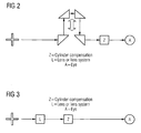
- Figure 2 shows a diagrammatic representation of a preferred embodiment of an automatic focusing of the target.
- the additional optical unit 18 comprises at least four deflection prisms 32-35, wherein these prisms are arranged so that they can be adjusted individually or in pairs together, as represented by the arrow 30.
- the optical path length is changed due to the mechanical movement path of the upper two prisms 33, 34.
- Figure 3 shows a diagrammatic representation of an additional preferred embodiment of an automatic focusing of the target.
- the arrangement of the optical unit 14 is replaced with the arrangement of the additional optical unit 18.
- the optical units being arranged next to one another, they can be mounted in a manner so that they can be moved with respect to one another by means of actuators, in order to adjust the image position, in particular the far point of the individual eye, fully automatically by means of actuators.
- Figure 4 diagrammatically shows the pictorial representation of the Zernike polynomial, for the purpose of describing the imaging properties of the eye.
- the tilt (inclination) Z1 and Z2 is achieved by lining up the patient in front of the target object, and the defocus Z4 is also achieved by a shifting the lens systems.
- the astigmatism Z3 and Z5 is taken into account in a new way, so that a target object having the above-described features of the invention can be provided, so that the individual accommodation variations of the respective patient are eliminated and an ametropia of the patient caused by 2 nd order aberrations is completely corrected.
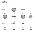
- Figure 5 diagrammatically shows possible designs of the target object 12, which are used as a variant of the possibility represented in Figure 3 .
- the target object 12 can be illuminated, or it can itself emit light by means of a light beam 16, so that special patterns can be perceived by the patient, which can also vary during the fixation, in order to maintain the concentration of the patient.
- a pattern can be configured to be perpendicular (or in any other angular arrangement) relative to the optical axis A with radially outward extending light segments (as indicated in Figure 3 ).
- Alternative geometric embodiment variants of the target objects can be seen in Figure 5 . Additional geometric shapes are also available to the person skilled in the art, such as, for example, stellate, round, elliptic shapes or polygonal bodies of any shape.
- the described invention can be used in all ophthalmological apparatuses in which the best possible quality of correction of the eye to be measured is to be achieved. Undesired secondary effects, such as accommodation or accommodation-induced spherical aberrations are largely prevented.
Landscapes
- Life Sciences & Earth Sciences (AREA)
- Health & Medical Sciences (AREA)
- Medical Informatics (AREA)
- Biophysics (AREA)
- Ophthalmology & Optometry (AREA)
- Engineering & Computer Science (AREA)
- Biomedical Technology (AREA)
- Heart & Thoracic Surgery (AREA)
- Physics & Mathematics (AREA)
- Molecular Biology (AREA)
- Surgery (AREA)
- Animal Behavior & Ethology (AREA)
- General Health & Medical Sciences (AREA)
- Public Health (AREA)
- Veterinary Medicine (AREA)
- Eye Examination Apparatus (AREA)
- Prostheses (AREA)
Abstract
Description
- The invention relates to a device offering a patient a sharp fixation target, for fixation on a diagnostic or therapeutic apparatus, independently of low-aberration sight defects of the patient. The term "sharp fixation target" here does not refer to the target itself, but to the sharpness of the representation in the perception of the patient.
- In numerous ophthalmological measurements and/or surgical interventions, the constant accommodation of a patient's eye is stabilized by offering the patient a target object (so-called target), typically in the form of a light source. The patient fixates (sights, looks at) this light source without interruption. In the process, the patient will unintentionally attempt to see the target object (target) sharply. However, if the fixating eye has aberrations, the focusing can only occur more or less incompletely.
- The known devices for the fixation of an eye according to the prior art take into account an ametropia of the eye only in terms of focusing relative to defocus, that is blurriness, which results from obtaining a sharp representation of a point to be pictured in front of or behind the retina. Such defocus is referred to as a low order aberration. In ophthalmology, the imaging properties of the eyes are usually represented with so-called Zernike polynomials. The defocus relates to the Zernike polynomial Z4 (see
Figure 4 ). In the prior art, an attempt is made to reduce the defocus during fixation, for example, by shifting the lenses or lens systems and/or by shifting the target object for the purpose of increasing or shortening the object distance. - The present invention is based on the finding that the currently offered solution in the prior art, in particular the correction of the blurriness of the fixation target based on defocus, does not make it possible for the patient to see the fixation target consistently sharply, in the case of the presence of further low order aberrations, so that, if queried, the patient generally indicates satisfaction with the least blurry result for psychological reasons.
- The fixation solution offered by the prior art in addition leads to inaccuracies with regard to both the measurement of the eye and an ophthalmological intervention. In the described prior art, the patient, in case further aberrations are present, for example, an astigmatism, can discern the target object (target) sharply always in only one main plane direction. This leads to a permanent change in the accommodation between the two main sections, or main planes, so that the patient cannot see the fixation target accurately or he/she can see it only with incomplete sharpness. As a result of the permanent change in accommodation, the measurement results are biased.
- The invention is based on the problem of offering a method and a device for stabilizing the constant accommodation of the patient's eye in the case of aberrations other than the defocus aberrations, in order to present the sharpest possible fixation target to the patient, and as a result allow not only a stable accommodation position but also improved measurement results with regard to the optical and anatomic properties of the eyes.
- In this context, the invention provides a method and a device for stabilizing the constant accommodations of a patient's eye, comprising:
- a target object which is arranged to be fixated by the patient along an optical axis
- an optical unit in the light path, which is arranged on the optical axis and is designed to compensate a lower order ametropia, for example, a spherical ametropia of the eye, partially or completely depending on the adjustment of the
optical unit 14, and - an additional optical unit in the light path, by means of which a higher order ametropia, for example, an astigmatic ametropia of the eye, can be compensated partially or completely depending on the adjustment of the
optical unit 14. - The method according to the invention entails in particular the following steps:
- a target object is arranged so that it can be fixated by a patient along an optical axis,
- an optical unit is arranged on the optical axis, in order to compensate thereby a lower order ametropia of the eye, for example, a spherical ametropia, partially or completely depending on the adjustment of the
optical unit 14, and - an additional optical unit is arranged in the light path, in order to compensate thereby an ametropia of higher order, for example, an astigmatic ametropia of the eye, partially or completely depending on the adjustment of the
optical unit 14. - The invention makes it possible, in particular, to provide the mentioned device as an automated device, wherein the mentioned optical units do not necessarily have to be actuated by hand (wherein simple designs can definitely allow a manual intervention).
- In particular, the device and the method according to the invention are suitable for stabilizing the accommodation of the eye in the case of the presence of additional low order aberrations (in addition to defocus).
- According to an embodiment of the invention, one of the optical units can comprise at least two optical components, for example, cylindrical lenses with toric effect, which are rotatably mounted, according to a further embodiment of the invention, around the optical axis. However, in an alternative embodiment of the invention, it is conceivable to focus the fixation target by means of several lenses with toric effect.
- If the above-mentioned optical units comprise two or more cylindrical lenses, then they can have a positive refraction power and also a negative refraction power. In a particular design of the invention, at least one cylindrical lens has a positive refraction power, while at least one other cylindrical lens, preferably arranged opposite, has a negative refraction power. In a further embodiment of the invention, depending on the application, it is also possible for at least two of the cylindrical lenses to have a positive refraction power or equivalent negative refraction power.
- In addition, the invention provides a device for measuring an eye, wherein the above-mentioned device for stabilizing in particular constant accommodation of an eye in an aberrometer, can be coupled into an aberrometer, an autorefractometer, a biometer or other diagnostic or therapeutic apparatus. Aberrometers as such are well known in the ophthalmological technology. For example, Hartmann-Shack and also Tscherning aberrometers are commonly used.
- In addition to providing a sharp fixation target, the invention also promotes the accuracy and reliability of a measurement of the eye, using, for example, an aberrometer, as well as the stability of the fixation of an eye during an ophthalmological intervention, compensating not only the defocus, but also astigmatic ametropia.
- By taking into consideration the sphero-cylindrical ametropia of the patient's eye during the sighting of the target object provided, it is possible to reduce to a minimum or completely eliminate the accommodation fluctuations and the ametropia of the patients that are the result of 2nd order aberrations by means of the above-described features of the invention.
- Possible embodiments of the invention are further explained below in reference to the figures.
-
Figure 1 diagrammatically shows a device for measuring an eye, in particular the imaging properties of the eye. -
Figure 2 shows a diagrammatic representation of an automatic focusing of the target. -
Figure 3 shows a diagrammatic representation of an additional embodiment of an automatic focusing of the target. -
Figure 4 diagrammatically shows the pictorial representation of the Zernike polynomial, for the purpose of describing the imaging properties of the eye. -
Figure 5 diagrammatically shows possible embodiments of the target object. -
Figure 1 shows a diagrammatic representation of the automatic focusing, according to the invention, of atarget object 12 for at least oneeye 10. Here, thetarget object 12 can be illuminated or it can itself emit light by means of alight beam 16. Thetarget object 12 is imaged in theeye 10 here in a manner which is known per se by means of anoptical unit 14. Theoptical unit 14 corrects, in a known manner, a possible defocus Z4 of theeye 10. In a preferred embodiment, theoptical unit 14 can be a lens system (not further represented), which is shifted automatically for the purpose of minimizing the defocus Z4 along the optical axis A, by means of actuators (not shown), individually for the patient, so that the patient can perceive the target object in accurate form. - In the represented embodiment example of the invention, an additional
optical unit 18 consists of at least twocylindrical lenses cylindrical lens 20 is perpendicular to the meridional line M of the othercylindrical lens 22. In the represented 90° position of the cylinder axes of the twocylindrical lenses cylindrical lenses - Furthermore,
Figure 1 shows the above-described device for stabilizing the constant accommodation of the patient's eye in the case of 2nd order aberrations, which is completed by ameasurement device 24, a Hartmann-Shack aberrometer in the embodiment example represented here. On the optical axis A of the fixation device formed by thetarget object 12, theoptical unit 14, and the additionaloptical unit 18, abeam splitter 28, for example, a semi-transparent mirror, is arranged, which reflects themeasurement radiation 26 of themeasurement device 24 along the axis A into theeye 10, and also themeasurement radiation 26 coming from the eye in the opposite direction toward themeasurement device 24. Likewise, thebeam splitter 28 is transparent to thelight beam 16 of thetarget object 12. - In the represented embodiment example, the additional
optical unit 18 comprises twocylindrical lenses - Based on the explanations of
Figure 1 ,Figure 2 shows a diagrammatic representation of a preferred embodiment of an automatic focusing of the target. For this purpose, the additionaloptical unit 18, in addition, comprises at least four deflection prisms 32-35, wherein these prisms are arranged so that they can be adjusted individually or in pairs together, as represented by the arrow 30. By means of this design, the optical path length is changed due to the mechanical movement path of the upper two prisms 33, 34. - Based on the explanations of
Figure 1 ,Figure 3 shows a diagrammatic representation of an additional preferred embodiment of an automatic focusing of the target. Here, in contrast toFigure 1 , the arrangement of theoptical unit 14 is replaced with the arrangement of the additionaloptical unit 18. As a result of the optical units being arranged next to one another, they can be mounted in a manner so that they can be moved with respect to one another by means of actuators, in order to adjust the image position, in particular the far point of the individual eye, fully automatically by means of actuators. - In this manner, it is possible to dispense with feedback from the patient regarding the perceived focusing of the target object, because a sharp fixation target adjusted especially for the existing ametropia is automatically presented to the patient. As a result, the fixation of the eye achieves the maximum possible constant stability.
-
Figure 4 diagrammatically shows the pictorial representation of the Zernike polynomial, for the purpose of describing the imaging properties of the eye. As already explained above, it is already known in the prior art to adjust the eye of the patient by orienting it towards a target object in order to conduct diagnostic measurements. For this purpose the tilt (inclination) Z1 and Z2 is achieved by lining up the patient in front of the target object, and the defocus Z4 is also achieved by a shifting the lens systems. According to the invention, the astigmatism Z3 and Z5 is taken into account in a new way, so that a target object having the above-described features of the invention can be provided, so that the individual accommodation variations of the respective patient are eliminated and an ametropia of the patient caused by 2nd order aberrations is completely corrected. -
Figure 5 diagrammatically shows possible designs of thetarget object 12, which are used as a variant of the possibility represented inFigure 3 . Here, thetarget object 12 can be illuminated, or it can itself emit light by means of alight beam 16, so that special patterns can be perceived by the patient, which can also vary during the fixation, in order to maintain the concentration of the patient. In particular, a pattern can be configured to be perpendicular (or in any other angular arrangement) relative to the optical axis A with radially outward extending light segments (as indicated inFigure 3 ). Alternative geometric embodiment variants of the target objects can be seen inFigure 5 . Additional geometric shapes are also available to the person skilled in the art, such as, for example, stellate, round, elliptic shapes or polygonal bodies of any shape. - The described invention can be used in all ophthalmological apparatuses in which the best possible quality of correction of the eye to be measured is to be achieved. Undesired secondary effects, such as accommodation or accommodation-induced spherical aberrations are largely prevented.
Claims (10)
- Device for stabilizing the constant accommodation of an eye (10) of a patient, comprising:- a target object (12) which is set up to be fixated by the patient along an optical axis (A),- an optical unit (14) in the light path from the target object to the eye, which is arranged on the optical axis (A) and is designed to compensate a lower order ametropia, for example, a spherical ametropia of the eye, and- an additional optical unit (18) in the light path, by means of which a higher order ametropia, for example, an astigmatic ametropia of the eye, can be compensated.
- Device according to Claim 1, wherein the second optical unit (18) comprises at least two cylindrical lenses (20, 22).
- Device according to Claim 2, wherein at least one of the cylindrical lenses is rotatably arranged around the optical axis.
- Device according to Claim 2 or 3, wherein one cylindrical lens has a positive refraction power and one other cylindrical lens has a negative refraction power.
- Device according to Claim 2 or 3, wherein two cylindrical lenses have positive refraction power.
- Device according to Claim 2 or 3, wherein two cylindrical lenses have negative refraction power.
- Device for measuring an eye of a patient, comprising:- an aberrometer (28) and- a device for the fixation of the eye according to one of Claims 1 to 6.
- Device according to Claim 7, wherein the aberrometer is a Hartmann-Shack aberrometer.
- Device according to Claim 7, wherein the aberrometer is a Tscherning aberrometer.
- Method for stabilizing the constant accommodation of an eye of a patient, comprising the following steps:- arranging a target object (12) so that it can be fixated by the patient along an optical axis (A),- compensating a lower order ametropia of the eye using an optical unit on the optical axis (A) and- compensating a higher order ametropia of the eye, for example, an astigmatic ametropia, using an optical unit on the axis.
Applications Claiming Priority (1)
| Application Number | Priority Date | Filing Date | Title |
|---|---|---|---|
| DE102014004248.0A DE102014004248A1 (en) | 2014-03-24 | 2014-03-24 | Sharp fixation target |
Publications (2)
| Publication Number | Publication Date |
|---|---|
| EP2923637A1 true EP2923637A1 (en) | 2015-09-30 |
| EP2923637B1 EP2923637B1 (en) | 2019-03-06 |
Family
ID=52828955
Family Applications (1)
| Application Number | Title | Priority Date | Filing Date |
|---|---|---|---|
| EP15000830.8A Active EP2923637B1 (en) | 2014-03-24 | 2015-03-20 | Sharp fixation target |
Country Status (8)
| Country | Link |
|---|---|
| US (1) | US9364141B2 (en) |
| EP (1) | EP2923637B1 (en) |
| KR (1) | KR101665605B1 (en) |
| CN (1) | CN104939801B (en) |
| AU (1) | AU2014271298B2 (en) |
| CA (1) | CA2872024C (en) |
| DE (1) | DE102014004248A1 (en) |
| ES (1) | ES2718030T3 (en) |
Families Citing this family (2)
| Publication number | Priority date | Publication date | Assignee | Title |
|---|---|---|---|---|
| DE102017129951B3 (en) | 2017-12-14 | 2019-05-09 | Medizinisches Laserzentrum Lübeck GmbH | Apparatus for ophthalmic gaze fixation for patients with any visual acuity |
| US20240041649A1 (en) * | 2022-08-03 | 2024-02-08 | Twenty Twenty Therapeutics Llc | Optimized concave mirror for horizontal eye spray apparatus with on-axis light guided user alignment |
Citations (4)
| Publication number | Priority date | Publication date | Assignee | Title |
|---|---|---|---|---|
| JP2005021181A (en) * | 2003-06-30 | 2005-01-27 | Nidek Co Ltd | Ocular accommodation measuring apparatus |
| US20070195264A1 (en) * | 2006-02-14 | 2007-08-23 | Lai Shui T | Subjective Refraction Method and Device for Correcting Low and Higher Order Aberrations |
| US20080284979A1 (en) * | 2007-05-17 | 2008-11-20 | Visx, Incorporated | System and Method for Illumination and Fixation with Ophthalmic Diagnostic Instruments |
| US20120002163A1 (en) * | 2010-07-02 | 2012-01-05 | Amo Wavefront Sciences, Llc | Compact Binocular Adaptive Optics Phoropter |
Family Cites Families (5)
| Publication number | Priority date | Publication date | Assignee | Title |
|---|---|---|---|---|
| DE2412059A1 (en) * | 1974-03-13 | 1975-09-18 | Humphrey Instruments Inc | Eye testing instrument - ascertains necessary correction of various astigmatic defects |
| US7494220B2 (en) * | 2002-06-27 | 2009-02-24 | Advanced Medical Optics, Inc. | Method and system for improving accuracy in autorefraction measurements by including measurement distance between the photorecptors and the scattering location in an eye |
| WO2005004708A1 (en) * | 2003-07-14 | 2005-01-20 | Right Mfg,Co.,Ltd. | Instrument for measuring eye adjusting function state |
| DE102005035870A1 (en) * | 2005-07-30 | 2007-02-01 | Carl Zeiss Meditec Ag | Optical scan system for medical applications such as in eye treatment which produces a fixation beam from a source controlled in synchrony with a moveable reflector |
| EP2872030B1 (en) * | 2012-07-10 | 2016-12-07 | WaveLight GmbH | Process and apparatus for determining optical aberrations of an eye |
-
2014
- 2014-03-24 DE DE102014004248.0A patent/DE102014004248A1/en not_active Withdrawn
- 2014-11-19 US US14/548,060 patent/US9364141B2/en active Active
- 2014-11-21 CA CA2872024A patent/CA2872024C/en not_active Expired - Fee Related
- 2014-12-04 AU AU2014271298A patent/AU2014271298B2/en not_active Ceased
-
2015
- 2015-01-07 CN CN201510006969.4A patent/CN104939801B/en not_active Expired - Fee Related
- 2015-03-20 ES ES15000830T patent/ES2718030T3/en active Active
- 2015-03-20 EP EP15000830.8A patent/EP2923637B1/en active Active
- 2015-03-23 KR KR1020150040093A patent/KR101665605B1/en not_active Expired - Fee Related
Patent Citations (4)
| Publication number | Priority date | Publication date | Assignee | Title |
|---|---|---|---|---|
| JP2005021181A (en) * | 2003-06-30 | 2005-01-27 | Nidek Co Ltd | Ocular accommodation measuring apparatus |
| US20070195264A1 (en) * | 2006-02-14 | 2007-08-23 | Lai Shui T | Subjective Refraction Method and Device for Correcting Low and Higher Order Aberrations |
| US20080284979A1 (en) * | 2007-05-17 | 2008-11-20 | Visx, Incorporated | System and Method for Illumination and Fixation with Ophthalmic Diagnostic Instruments |
| US20120002163A1 (en) * | 2010-07-02 | 2012-01-05 | Amo Wavefront Sciences, Llc | Compact Binocular Adaptive Optics Phoropter |
Also Published As
| Publication number | Publication date |
|---|---|
| EP2923637B1 (en) | 2019-03-06 |
| AU2014271298A1 (en) | 2015-10-08 |
| CA2872024A1 (en) | 2015-09-24 |
| DE102014004248A1 (en) | 2015-10-08 |
| ES2718030T3 (en) | 2019-06-27 |
| AU2014271298B2 (en) | 2019-08-08 |
| KR20150110416A (en) | 2015-10-02 |
| CA2872024C (en) | 2016-12-06 |
| US20150265145A1 (en) | 2015-09-24 |
| CN104939801A (en) | 2015-09-30 |
| CN104939801B (en) | 2018-06-29 |
| KR101665605B1 (en) | 2016-10-12 |
| US9364141B2 (en) | 2016-06-14 |
Similar Documents
| Publication | Publication Date | Title |
|---|---|---|
| US8684526B2 (en) | Compact binocular adaptive optics phoropter | |
| JP6961059B2 (en) | How to calibrate the phoropter wheel assembly of an object folopter incorporating a wave surface analyzer | |
| US7802886B2 (en) | Ophthalmic apparatus | |
| US20110202017A1 (en) | Measurement system and method for establishing the refraction of an eye, the radius of curvature of the cornea or the internal pressure of an eye | |
| JP2019166345A (en) | Device for determining ophthalmological data | |
| CN110367924A (en) | A kind of accurate optometry equipment of subjective and objective integral type and optometry method | |
| EP2923637B1 (en) | Sharp fixation target | |
| US9788718B2 (en) | Surgical microscope | |
| US7281798B2 (en) | Optometry apparatus | |
| CN113208554A (en) | Optometry device with defocusing and astigmatism accurate correction functions and optometry method | |
| US20230309814A1 (en) | Ophthalmologic apparatus | |
| JP7367509B2 (en) | Ophthalmology measurement equipment, ophthalmology measurement system, and ophthalmology measurement program | |
| CN106659379A (en) | Technique for centering an application field | |
| US20230064504A1 (en) | System for combined intraoperative aberrometry and optical coherence tomography | |
| US12458228B2 (en) | Ophthalmologic apparatus for determining whether accommodation intervention by subject eye has occurred | |
| JP7859140B2 (en) | ophthalmology equipment | |
| JP7859139B2 (en) | ophthalmology equipment | |
| JP2025058665A (en) | Ophthalmic Equipment | |
| JP2025104372A (en) | Optometry Equipment | |
| Carroll et al. | The Fixational Stability of the Human Eye Measured by Imaging the Cone Mosaic. |
Legal Events
| Date | Code | Title | Description |
|---|---|---|---|
| PUAI | Public reference made under article 153(3) epc to a published international application that has entered the european phase |
Free format text: ORIGINAL CODE: 0009012 |
|
| AK | Designated contracting states |
Kind code of ref document: A1 Designated state(s): AL AT BE BG CH CY CZ DE DK EE ES FI FR GB GR HR HU IE IS IT LI LT LU LV MC MK MT NL NO PL PT RO RS SE SI SK SM TR |
|
| AX | Request for extension of the european patent |
Extension state: BA ME |
|
| 17P | Request for examination filed |
Effective date: 20151103 |
|
| RBV | Designated contracting states (corrected) |
Designated state(s): AL AT BE BG CH CY CZ DE DK EE ES FI FR GB GR HR HU IE IS IT LI LT LU LV MC MK MT NL NO PL PT RO RS SE SI SK SM TR |
|
| STAA | Information on the status of an ep patent application or granted ep patent |
Free format text: STATUS: EXAMINATION IS IN PROGRESS |
|
| 17Q | First examination report despatched |
Effective date: 20161107 |
|
| RAP1 | Party data changed (applicant data changed or rights of an application transferred) |
Owner name: NOVARTIS AG |
|
| GRAP | Despatch of communication of intention to grant a patent |
Free format text: ORIGINAL CODE: EPIDOSNIGR1 |
|
| STAA | Information on the status of an ep patent application or granted ep patent |
Free format text: STATUS: GRANT OF PATENT IS INTENDED |
|
| INTG | Intention to grant announced |
Effective date: 20180928 |
|
| GRAS | Grant fee paid |
Free format text: ORIGINAL CODE: EPIDOSNIGR3 |
|
| GRAA | (expected) grant |
Free format text: ORIGINAL CODE: 0009210 |
|
| STAA | Information on the status of an ep patent application or granted ep patent |
Free format text: STATUS: THE PATENT HAS BEEN GRANTED |
|
| RIN1 | Information on inventor provided before grant (corrected) |
Inventor name: WEBER, MAREC |
|
| AK | Designated contracting states |
Kind code of ref document: B1 Designated state(s): AL AT BE BG CH CY CZ DE DK EE ES FI FR GB GR HR HU IE IS IT LI LT LU LV MC MK MT NL NO PL PT RO RS SE SI SK SM TR |
|
| REG | Reference to a national code |
Ref country code: GB Ref legal event code: FG4D |
|
| REG | Reference to a national code |
Ref country code: CH Ref legal event code: EP Ref country code: AT Ref legal event code: REF Ref document number: 1103463 Country of ref document: AT Kind code of ref document: T Effective date: 20190315 |
|
| REG | Reference to a national code |
Ref country code: DE Ref legal event code: R096 Ref document number: 602015025665 Country of ref document: DE |
|
| REG | Reference to a national code |
Ref country code: IE Ref legal event code: FG4D |
|
| PGFP | Annual fee paid to national office [announced via postgrant information from national office to epo] |
Ref country code: NL Payment date: 20190129 Year of fee payment: 12 |
|
| REG | Reference to a national code |
Ref country code: ES Ref legal event code: FG2A Ref document number: 2718030 Country of ref document: ES Kind code of ref document: T3 Effective date: 20190627 |
|
| REG | Reference to a national code |
Ref country code: NL Ref legal event code: MP Effective date: 20190306 |
|
| REG | Reference to a national code |
Ref country code: LT Ref legal event code: MG4D |
|
| PG25 | Lapsed in a contracting state [announced via postgrant information from national office to epo] |
Ref country code: LT Free format text: LAPSE BECAUSE OF FAILURE TO SUBMIT A TRANSLATION OF THE DESCRIPTION OR TO PAY THE FEE WITHIN THE PRESCRIBED TIME-LIMIT Effective date: 20190306 Ref country code: NO Free format text: LAPSE BECAUSE OF FAILURE TO SUBMIT A TRANSLATION OF THE DESCRIPTION OR TO PAY THE FEE WITHIN THE PRESCRIBED TIME-LIMIT Effective date: 20190606 Ref country code: SE Free format text: LAPSE BECAUSE OF FAILURE TO SUBMIT A TRANSLATION OF THE DESCRIPTION OR TO PAY THE FEE WITHIN THE PRESCRIBED TIME-LIMIT Effective date: 20190306 Ref country code: FI Free format text: LAPSE BECAUSE OF FAILURE TO SUBMIT A TRANSLATION OF THE DESCRIPTION OR TO PAY THE FEE WITHIN THE PRESCRIBED TIME-LIMIT Effective date: 20190306 |
|
| PGFP | Annual fee paid to national office [announced via postgrant information from national office to epo] |
Ref country code: IT Payment date: 20190507 Year of fee payment: 5 Ref country code: ES Payment date: 20190401 Year of fee payment: 5 |
|
| PG25 | Lapsed in a contracting state [announced via postgrant information from national office to epo] |
Ref country code: GR Free format text: LAPSE BECAUSE OF FAILURE TO SUBMIT A TRANSLATION OF THE DESCRIPTION OR TO PAY THE FEE WITHIN THE PRESCRIBED TIME-LIMIT Effective date: 20190607 Ref country code: NL Free format text: LAPSE BECAUSE OF FAILURE TO SUBMIT A TRANSLATION OF THE DESCRIPTION OR TO PAY THE FEE WITHIN THE PRESCRIBED TIME-LIMIT Effective date: 20190306 Ref country code: RS Free format text: LAPSE BECAUSE OF FAILURE TO SUBMIT A TRANSLATION OF THE DESCRIPTION OR TO PAY THE FEE WITHIN THE PRESCRIBED TIME-LIMIT Effective date: 20190306 Ref country code: BG Free format text: LAPSE BECAUSE OF FAILURE TO SUBMIT A TRANSLATION OF THE DESCRIPTION OR TO PAY THE FEE WITHIN THE PRESCRIBED TIME-LIMIT Effective date: 20190606 Ref country code: LV Free format text: LAPSE BECAUSE OF FAILURE TO SUBMIT A TRANSLATION OF THE DESCRIPTION OR TO PAY THE FEE WITHIN THE PRESCRIBED TIME-LIMIT Effective date: 20190306 Ref country code: HR Free format text: LAPSE BECAUSE OF FAILURE TO SUBMIT A TRANSLATION OF THE DESCRIPTION OR TO PAY THE FEE WITHIN THE PRESCRIBED TIME-LIMIT Effective date: 20190306 |
|
| REG | Reference to a national code |
Ref country code: AT Ref legal event code: MK05 Ref document number: 1103463 Country of ref document: AT Kind code of ref document: T Effective date: 20190306 |
|
| PG25 | Lapsed in a contracting state [announced via postgrant information from national office to epo] |
Ref country code: SK Free format text: LAPSE BECAUSE OF FAILURE TO SUBMIT A TRANSLATION OF THE DESCRIPTION OR TO PAY THE FEE WITHIN THE PRESCRIBED TIME-LIMIT Effective date: 20190306 Ref country code: AL Free format text: LAPSE BECAUSE OF FAILURE TO SUBMIT A TRANSLATION OF THE DESCRIPTION OR TO PAY THE FEE WITHIN THE PRESCRIBED TIME-LIMIT Effective date: 20190306 Ref country code: PT Free format text: LAPSE BECAUSE OF FAILURE TO SUBMIT A TRANSLATION OF THE DESCRIPTION OR TO PAY THE FEE WITHIN THE PRESCRIBED TIME-LIMIT Effective date: 20190706 Ref country code: CZ Free format text: LAPSE BECAUSE OF FAILURE TO SUBMIT A TRANSLATION OF THE DESCRIPTION OR TO PAY THE FEE WITHIN THE PRESCRIBED TIME-LIMIT Effective date: 20190306 Ref country code: EE Free format text: LAPSE BECAUSE OF FAILURE TO SUBMIT A TRANSLATION OF THE DESCRIPTION OR TO PAY THE FEE WITHIN THE PRESCRIBED TIME-LIMIT Effective date: 20190306 Ref country code: RO Free format text: LAPSE BECAUSE OF FAILURE TO SUBMIT A TRANSLATION OF THE DESCRIPTION OR TO PAY THE FEE WITHIN THE PRESCRIBED TIME-LIMIT Effective date: 20190306 |
|
| PG25 | Lapsed in a contracting state [announced via postgrant information from national office to epo] |
Ref country code: SM Free format text: LAPSE BECAUSE OF FAILURE TO SUBMIT A TRANSLATION OF THE DESCRIPTION OR TO PAY THE FEE WITHIN THE PRESCRIBED TIME-LIMIT Effective date: 20190306 Ref country code: PL Free format text: LAPSE BECAUSE OF FAILURE TO SUBMIT A TRANSLATION OF THE DESCRIPTION OR TO PAY THE FEE WITHIN THE PRESCRIBED TIME-LIMIT Effective date: 20190306 Ref country code: LU Free format text: LAPSE BECAUSE OF NON-PAYMENT OF DUE FEES Effective date: 20190320 |
|
| REG | Reference to a national code |
Ref country code: BE Ref legal event code: MM Effective date: 20190331 |
|
| REG | Reference to a national code |
Ref country code: DE Ref legal event code: R097 Ref document number: 602015025665 Country of ref document: DE |
|
| REG | Reference to a national code |
Ref country code: CH Ref legal event code: PUE Owner name: ALCON INC., CH Free format text: FORMER OWNER: NOVARTIS AG, CH |
|
| PG25 | Lapsed in a contracting state [announced via postgrant information from national office to epo] |
Ref country code: AT Free format text: LAPSE BECAUSE OF FAILURE TO SUBMIT A TRANSLATION OF THE DESCRIPTION OR TO PAY THE FEE WITHIN THE PRESCRIBED TIME-LIMIT Effective date: 20190306 Ref country code: IS Free format text: LAPSE BECAUSE OF FAILURE TO SUBMIT A TRANSLATION OF THE DESCRIPTION OR TO PAY THE FEE WITHIN THE PRESCRIBED TIME-LIMIT Effective date: 20190706 |
|
| PLBE | No opposition filed within time limit |
Free format text: ORIGINAL CODE: 0009261 |
|
| STAA | Information on the status of an ep patent application or granted ep patent |
Free format text: STATUS: NO OPPOSITION FILED WITHIN TIME LIMIT |
|
| PG25 | Lapsed in a contracting state [announced via postgrant information from national office to epo] |
Ref country code: DK Free format text: LAPSE BECAUSE OF FAILURE TO SUBMIT A TRANSLATION OF THE DESCRIPTION OR TO PAY THE FEE WITHIN THE PRESCRIBED TIME-LIMIT Effective date: 20190306 Ref country code: MC Free format text: LAPSE BECAUSE OF FAILURE TO SUBMIT A TRANSLATION OF THE DESCRIPTION OR TO PAY THE FEE WITHIN THE PRESCRIBED TIME-LIMIT Effective date: 20190306 Ref country code: IE Free format text: LAPSE BECAUSE OF NON-PAYMENT OF DUE FEES Effective date: 20190320 |
|
| 26N | No opposition filed |
Effective date: 20191209 |
|
| REG | Reference to a national code |
Ref country code: DE Ref legal event code: R081 Ref document number: 602015025665 Country of ref document: DE Owner name: ALCON INC., CH Free format text: FORMER OWNER: NOVARTIS AG, BASEL, CH |
|
| REG | Reference to a national code |
Ref country code: GB Ref legal event code: 732E Free format text: REGISTERED BETWEEN 20200123 AND 20200129 |
|
| PG25 | Lapsed in a contracting state [announced via postgrant information from national office to epo] |
Ref country code: SI Free format text: LAPSE BECAUSE OF FAILURE TO SUBMIT A TRANSLATION OF THE DESCRIPTION OR TO PAY THE FEE WITHIN THE PRESCRIBED TIME-LIMIT Effective date: 20190306 Ref country code: BE Free format text: LAPSE BECAUSE OF NON-PAYMENT OF DUE FEES Effective date: 20190331 |
|
| PG25 | Lapsed in a contracting state [announced via postgrant information from national office to epo] |
Ref country code: TR Free format text: LAPSE BECAUSE OF FAILURE TO SUBMIT A TRANSLATION OF THE DESCRIPTION OR TO PAY THE FEE WITHIN THE PRESCRIBED TIME-LIMIT Effective date: 20190306 |
|
| REG | Reference to a national code |
Ref country code: ES Ref legal event code: PC2A Owner name: ALCON INC. Effective date: 20200416 |
|
| PG25 | Lapsed in a contracting state [announced via postgrant information from national office to epo] |
Ref country code: MT Free format text: LAPSE BECAUSE OF NON-PAYMENT OF DUE FEES Effective date: 20190320 |
|
| REG | Reference to a national code |
Ref country code: CH Ref legal event code: PL |
|
| PG25 | Lapsed in a contracting state [announced via postgrant information from national office to epo] |
Ref country code: LI Free format text: LAPSE BECAUSE OF NON-PAYMENT OF DUE FEES Effective date: 20200331 Ref country code: CH Free format text: LAPSE BECAUSE OF NON-PAYMENT OF DUE FEES Effective date: 20200331 |
|
| PG25 | Lapsed in a contracting state [announced via postgrant information from national office to epo] |
Ref country code: CY Free format text: LAPSE BECAUSE OF FAILURE TO SUBMIT A TRANSLATION OF THE DESCRIPTION OR TO PAY THE FEE WITHIN THE PRESCRIBED TIME-LIMIT Effective date: 20190306 |
|
| PG25 | Lapsed in a contracting state [announced via postgrant information from national office to epo] |
Ref country code: HU Free format text: LAPSE BECAUSE OF FAILURE TO SUBMIT A TRANSLATION OF THE DESCRIPTION OR TO PAY THE FEE WITHIN THE PRESCRIBED TIME-LIMIT; INVALID AB INITIO Effective date: 20150320 |
|
| REG | Reference to a national code |
Ref country code: ES Ref legal event code: FD2A Effective date: 20210730 |
|
| PG25 | Lapsed in a contracting state [announced via postgrant information from national office to epo] |
Ref country code: IT Free format text: LAPSE BECAUSE OF NON-PAYMENT OF DUE FEES Effective date: 20200320 |
|
| PG25 | Lapsed in a contracting state [announced via postgrant information from national office to epo] |
Ref country code: ES Free format text: LAPSE BECAUSE OF NON-PAYMENT OF DUE FEES Effective date: 20200321 |
|
| PG25 | Lapsed in a contracting state [announced via postgrant information from national office to epo] |
Ref country code: MK Free format text: LAPSE BECAUSE OF FAILURE TO SUBMIT A TRANSLATION OF THE DESCRIPTION OR TO PAY THE FEE WITHIN THE PRESCRIBED TIME-LIMIT Effective date: 20190306 |
|
| P01 | Opt-out of the competence of the unified patent court (upc) registered |
Effective date: 20230504 |
|
| PGFP | Annual fee paid to national office [announced via postgrant information from national office to epo] |
Ref country code: GB Payment date: 20260223 Year of fee payment: 12 |
|
| PGFP | Annual fee paid to national office [announced via postgrant information from national office to epo] |
Ref country code: DE Payment date: 20260218 Year of fee payment: 12 |
|
| PGFP | Annual fee paid to national office [announced via postgrant information from national office to epo] |
Ref country code: FR Payment date: 20260223 Year of fee payment: 12 |